Embed Size (px)
Citation preview
26th INTERNATIONAL CONGRESS OF THE AERONAUTICAL SCIENCES
CEASIOM: SIMULATING STABILITY & CONTROL WITHCFD/CSM IN AIRCRAFT CONCEPTUAL DESIGN
R. von Kaenel∗, A. Rizzi∗∗, J. Oppelstrup†, T. Goetzendorf-Grabowski††, M. Ghoreyshi‡, L.Cavagna⋆, A. Bérard∗∗
∗ Computational Fluids and Structures Engineering (CFS), PSE-B, Lausanne, Switzerland∗∗ Dept. of Aeronautical & Vehicle Engineering,
Royal Institute of Technology (KTH), Stockholm, Sweden† School of Computer Science & Communication,
Royal Institute of Technology (KTH), Stockholm, Sweden†† The Faculty of Power and Aeronautical Engineering,
Warsaw University of Technology, Poland‡ Department of Engineering, University of Liverpool, Liverpool, UK
⋆ Dipartimento di Ingegneria Aerospaziale, Politecnico di Milano, Italy
Keywords: Aircraft design, aerodynamics, flight dynamics, flight control, CFD.
Abstract
An overview is given of CEASIOM, the Com-puterized Environment for Aircraft Synthesis andIntegrated Optimization Methods. The bench-mark for validation is the F12 windtunnel modelof a generic long-range airliner. First results forthe design of the Transonic Cruiser (TCR) high-speed passenger transport concept are presented.
1 Introduction
Present trends in aircraft design towardsaugmented-stability and expanded flight en-velopes call for an accurate description of theflight-dynamic behaviour of the aircraft in orderto properly design the flight control system(FCS). Hence the need to increase knowledgeabout stability and control (S&C) as early aspossible in the aircraft development process inorder to be "First-time-right" with the FCS de-sign architecture. The review paper by Vos et al.[1] describes these ideas in terms of the ‘VirtualProduct’ and explains much of the backgroundmotivation for our work here. The starting pointand inspiration for the software development
leading to the present CEASIOM (ComputerizedEnvironment for Aircraft Synthesis and Inte-grated Optimization Methods) was provided byIsikveren [2], who developed theMATLABTM[3]QCARD package for aircraft conceptual designwith quasi-analytical shape definitions, aero-datacorrelations, and performance predictions.
In order to address this need, developmentof the CEASIOM simulation system is currentlyunderway. The CEASIOM code is developedwithin the frame of the SimSAC (Simulating Air-craft Stability And Control Characteristics forUse in Conceptual Design) Specific TargetedResearch Project (STREP) approved for fund-ing by the European Commission 6th Frame-work Programme on Research, TechnologicalDevelopment and Demonstration. Work began 1November 2006 and continues for 3 years, (seewww.simsacdesign.eu). The SimSAC projectaims at significantly enhancing CEASIOM func-tionality by introducing software that initiallywill focus on rapid low fidelity analysis, andas appropriate, resort to higher fidelity numeri-cal simulations. Moreover CEASIOM will in-volve stability and control driven sizing and opti-mization earlier in the design cycle than is stan-
1

R. VON KAENEL et al.
Fig. 1 Raymer’s illustration [4] of the conceptual design processsegmented into two cycles: the initiallayout and the revised layout. CEASIOM focuses in particular on the S&C, structural-aeroelastic, andperformance characteristics of the aircraft.(c©Daniel Raymer with permission)
dard practice today. CEASIOM runs under eitherWindows or Linux, and its basic version requiresa MATLAB license only. In executable form thecode can be run without a license.
Referring to Fig. 1 taken from Raymer’s text-book [4], CEASIOM is meant to support engi-neers in the conceptual design process of the air-craft, with emphasis on the improved predictionof stability and control properties achieved byhigher-fidelity methods than found in contempo-rary aircraft design tools. Moreover CEASIOMwill integrate into one application the main de-sign disciplines, aerodynamics, structures, andflight dynamics, impacting on the aircraft’s per-formance. It is thus a tri-disciplinary analysisbrought to bear on the design of the aero-servo-elastic aircraft. CEASIOM does not howevercarry out the entire conceptual design process.It requires as input an initial layout as the base-line configuration that it then refines and outputsas the revised layout. In doing this, CEASIOM,through its simulation modules, generates signif-icant knowledge about the design in the perfor-mance, loads, and stability and control databases,
see Fig 2. The information contained in thesedatabases is sufficient input to a six Degree ofFreedom engineering flight simulator, such as theEFS system developed by Wakayama and Kroo[5].
This paper provides an overview of the cur-rent status and planned development on the CEA-SIOM simulation system .
Fig. 2 CEASIOM by simulation constructs thestability and control, loads, and performancedatabases of the revised layout design.
2

CEASIOM: Simulating Stability & Control with CFD/CSM in Air craft Conceptual Design
2 CEASIOM
Figure 3 presents an overview of the CEASIOMsoftware, showing aspects of its functionality,process and dataflow. Significant features are de-veloped and integrated in CEASIOM as modules:
1. The Geometry module CADacA CAD-centric solid geometry construc-tion system coupled to the user’s own CADand mesh generation systems by interfac-ing CEASIOM with MIT’s ComputationalAnalysis Programming Interface (CAPRI)
2. The Aerodynamic module AMB-CFDA replacement of current handbook aero-dynamic methods with new adaptable-fidelity modules referred to as tier I (a. andb.) and tier II (c.):
a. Steady and unsteady TORNADOvortex-lattice code (VLM) forlow-speed aerodynamics and aero-elasticity
b. Inviscid Edge CFD code forhigh-speed aerodynamics and aero-elasticity
c. RANS (Reynolds Averaged Navier-Stokes) flow simulator for high-fidelity analysis of extreme flight con-ditions
3. The Stability and Control module S&CA static and dynamic stability and con-trol analyser and flying-quality assessor.Test flights with six Degrees of Freedomflight simulation, and performance predic-tion are among the major functionalities ofthis module. The user can choose betweentwo variants:
i. SDSA (Simulation and DynamicStability Analysis), the SimSAC-developed and license-free softwarewhich includes a LQR-based flightcontrol system package , or
ii. J2 Universal Tool-Kit, thecommercially-available industrial-grade engineering analysis toolfor assessment and visualiza-tion of aircraft in flight. (seewww.j2aircraft.com)
4. The Aeroelastic module NeoCASSQuasi-analytical structural analysis meth-ods that support aero-elastic problem for-mulation and solution
5. The Flight Control System design moduleFCSDTA designer toolkit for flight control-lawformulation, simulation and technical deci-sion support, permitting flight control sys-tem design philosophy and architecture tobe coupled in early in the conceptual de-sign phase
6. The Decision Support System module DSSAn explicit DSS functionality, including is-sues such as fault tolerance and failure treeanalysis.
CEASIOM interfaces for seamless integra-tion also with the J2 Universal software devel-oped by the CEASIOM partner J2 Aircraft Dy-namics, Ltd. (www.j2aircraft.com) are being setup. The flight control system design packagesare under development by the CEASIOM part-ners Bristol University (http://www.bris.ac.uk/)and TsAGI (http://www.tsagi.ru/eng/). They em-ploy H∞-control law formulation and parameteroptimization, and will provide a simple interfacesatisfactory for most users, as well as detailed in-teraction required by expert users. These devel-opments are being reported elsewhere (e.g. see[6]. For this reason, the focus of the present paperis on modules 1 to 4. The following paragraphsgive an overview of these modules.
2.1 Geometric module CADac
Most dedicated aircraft conceptual design pack-ages with Computer-Aided Engineering (CAE)capability such as RDS [4], Piano [7], AAA [8],and ACSYNT [9] typically construct a simple
3

R. VON KAENEL et al.
Fig. 3 CEASIOM software consists of modules CADac, NeoCASS, AMB-CFD, S&C, FCSDT andDSS, and interfaces to theJ2 Universalpackage.
3D aircraft model by geometrical lofting tech-niques. The obtained geometrical definition issufficient for a designer to quickly estimate futureperformance of a design. But it does not allowconstruction of a computational mesh for higherfidelity analysis without extensive re-formattingand CAD repair. Thus, these tools neither sup-port increasing sophistication in geometric defi-nition with growing design maturity nor compat-ibility with industrial-grade CAD software, andengineers need to (re-)create the configuration af-ter the initial design phase as a CAD model.
The CADac (CAD-aircraft) tool [10] createsa proper CAD model from parameters which areintuitive and informative, such as aspect ratio,quarter chord sweep, area, etc., used by the de-signer to describe the aircraft morphology. A ma-jor innovation of CEASIOM is the functionalityto automaticallyproduce from these parametersa meshable CAD model for further analysis withtier I and II methods.
Different CAD systems differ in details, yetare sufficiently similar to enable the definition ofa common user interface powerful enough to sup-port the generation of appropriate CAD modelsfor CFD. What is needed from the CAD system
is a "meshable model" that grid generators willaccept without need for CAD repair. The Ap-plication Programming Interface (API) CAPRI[11] (www.cadnexus.com) offers this function-ality and generates this three dimensional solidmodel in CADac.A hierarchical component based approach hasbeen adopted. Each component (fuselage, wing,tail, etc.) is fully described by a finite set ofparameters stored in a unique XML file. Suchcomponent libraries have been created in fourmajor CAD systems: SolidWorks, Unigraphics,Pro Engineer and CATIA, allowing designersto use their favorite environment. The differ-ent components of the aircraft are loaded fromthis component library, then sized and assembledin order to create the meshable solid model ofthe complete aircraft (see Fig. 4). Both sur-face meshes for panel methods and CFD vol-ume meshes for Euler or RANS calculations canbe produced. Automatic grid-generators suchasTetGen (www.tetgen.berlios.de) can gener-ate, with minimal user intervention, the compu-tational meshes for Euler flow computations.
4

CEASIOM: Simulating Stability & Control with CFD/CSM in Air craft Conceptual Design
Fig. 4 CADac process: from parameters via a component library to a meshable model. The meshablemodel can subsequently be used directly as input by the Tier Ior II solvers of the Aerodynamic moduleAMB-CFD.
2.2 Aerodynamic module AMB-CFD
A prerequisite for realistic prediction of the S&Cbehavior and sizing of the FCS is the availabilityof complete and accurate aerodata (i.e. the S&Cdatabase). Traditionally, wind-tunnel measure-ments are used to fill look-up tables of forces andmoments over the flight envelope but wind-tunnelmodels become available only late in the designcycle. To date, most engineering tools for aircraftdesign rely on handbook methods or linear fluidmechanics assumptions. The latter methods pro-vide low cost reliable aerodata as long as the air-craft remains well within the limits of the flightenvelope. However, current trends in aircraft de-sign towards augmented-stability and expandedflight envelopes require an accurate descriptionof the non-linear flight-dynamic behaviour of theaircraft. The obvious option is to use Computa-tional Fluid Dynamics (CFD) early in the designcycle. It has the predictive capability to generatedata but the computational cost is problematic,particularly if done by brute force: a calculationfor every entry in the table. Fortunately methodsare available that can reduce the computationalcost.
There are essentially three issues, see Fig 5.First, a spectrum of computational tools are avail-
able, from RANS to potential flow models andsemi-empirical methods. Each of the tools has arange of validity which can be exploited to keepthe computational cost down. For the preliminarydesign of the aircraft and its FCS and as long asthe flight attitude remains well within the limitsof the flight envelope in the range of low-speedaerodynamics, tier I computational methods canprovide the aerodata.For a refined design of the FCS or for flight at-titudes close to the border of the flight envelope,the linear or inviscid methods used in the tier Itools fail to predict the proper aerodynamic be-havior and tier II RANS methods will be usedto derive the aerodata. In addition, data fusioncan be used for data from different methods, withlow fidelity / low cost data indicating trends anda small number of high fidelity / high cost simu-lations correcting the values.Secondly, interpolation methods can significantlyreduce the number of data points which actuallyneed to be computed to fill the table. Some stud-ies [12, 13, 14] of using kriging for the generationof aerodynamic data have been published.Thirdly, the identification of parameter regionswhere the aerodynamics is nonlinear, and hencewhere tier II fidelity is needed, is asamplingproblem. Therefore CEASIOM’s Aerodynamic
5

R. VON KAENEL et al.
Fig. 5 AMB-CFD architecture
module develops along with these three elements.A range of computational tools are available
in CEASIOM. TORNADO [15], a vortex-latticemethod for conceptual aircraft design and educa-tion has been integrated into CEASIOM as themain tier I tool. TORNADO allows a user to de-fine most types of contemporary aircraft designswith multiple wings, both cranked and twistedwith multiple control surfaces located at the trail-ing edge. Each wing is permitted to have uniquedefinitions of both camber and chord. The TOR-NADO solver computes forces, moments, and theassociated aerodynamic coefficients. The aero-dynamic derivatives can be calculated with re-spect to: angle of attack, angle of sideslip, roll-pitch-yaw rotations, and control surface deflec-tions.
To account for viscous effects, CEA-SIOM provides a correction to the steadyvortex lattice method by the strip theorythat combines the linear potential resultswith the 2D viscous airfoil code XFOIL(http://web.mit.edu/drela/Public/web/xfoil/).A basic unsteady version of TORNADO iscurrently under development in CEASIOM.Slightly more elaborate than vortex latticemethods is the inviscid version of theEdgeCFD code [16] (www.foi.se/edge) that has beenselected to determine the aerodata for transonicflight.
A first exercise with the Horizon 1100 aircraftaimed at checking the quality of the CAD solidmodel created by CAPRI and the completesimulation procedure from simple analyticalaircraft description to CAD description, auto-matic meshing and CFD solution [17]. TheEdge solver gave a fully converged result in 800MultiGrid four-level cycles on a modern laptopin 15 minutes (see Fig. 4), and all the stepsdescribed above took less than one and a halfhour, with minimal user intervention.
No tier II CFD tools are currently embeddedin CEASIOM because users are mainly interestedin coupling their own RANS CFD tools. There-fore only standard interfaces and file formats aredefined in CEASIOM to which different RANSsolvers can be coupled.
2.3 Aeroelastic module NeoCASS
It is well known that the aerodynamic forces in-duce structural deformations which in turn willaffect performance and S&C characteristics. Theforces and the structural deformations can bestatic, e.g. the wingtip flex due to the wing’s ownweight and lift distribution, ordynamic, e.g. wingor tail buffeting or transonic flutter. To accountfor the effect of these loads on the structure of theaircraft, aeroelastic models have been coupled tothe tier I aerodynamic tools.
The NeoCASS (Next generation Aero Struc-
6

CEASIOM: Simulating Stability & Control with CFD/CSM in Air craft Conceptual Design
Fig. 6 Architecture, function and process of NeoCASS
tural Sizing) module combines state of theart computational, analytical and semi-empiricalmethods to tackle all the aspects of the aero-structural analysis of a design layout at the con-ceptual design stage (see [18] and [19]). It givesa global understanding of the problem at handwithout neglecting any aspect of it: aerodynamic,structural and aeroelastic analysis from low tohigh speed regimes, buffet onset, divergence,flutter analysis and determination of trimmedcondition and stability derivatives both for rigidand deformable aircraft.The aerodynamic data in NeoCASS are providedby the tools presented in section 2.2 accordingto the desired fidelity level. The buffet enve-lope is estimated using a newly developed semi-empirical tool [20]. Buffet onset prediction isusually performed much later in the conceptualdesign phase, a somewhat constrained procedurebecause the geometry of the future airplane is bythen quite fixed. Such a situation hampers gen-eration of better designs since the buffet onset ishighly dependent on the geometry. By bringingthe analysis up-front in the design process, Neo-CASS ensures that this important feature is notneglected.
Two classic lifting surface methods are im-plemented. The Vortex Lattice Method (VLM)is used for subsonic steady aerodynamic andaeroelastic calculations, and the Doublet Lattice
Method (DLM) for subsonic flutter analysis andprediction of harmonic stability derivatives. Forhigher fidelity and higher Mach number CEA-SIOM uses the inviscid version of the CFD codeEdge. Aeroelastic analyses and control surfacedeflections are carried out by the transpirationboundary-condition method which accounts forstructural motion and deformation by specify-ing the velocity direction at the wall [20]. Thismethod avoids complex and time-consuming re-meshing as well as sliding mesh techniques andthe meshing of narrow gaps.Similarly to the aerodynamic module, structuralmodels of increasing accuracy and computationalcost provide consistent structural representationof the aircraft from the early conceptual defi-nition until the late detailed definition (see Fig.6). Preliminary analysis is focused on determin-ing and representing a reasonable structural/non-structural mass and stiffness distribution whichsatisfies strength, stiffness and stability require-ments. A few structural elements capable of giv-ing equivalent structural behaviour are available,such as a linear equivalent plate and a linear/non-linear equivalent beam to introduce geometrynon-linear effects. These models lead to low-order algebraic problems, keeping the computa-tional cost very low and allowing several config-urations to be examined quickly.
Flutter analyses are carried out by Reduced
7
R. VON KAENEL et al.
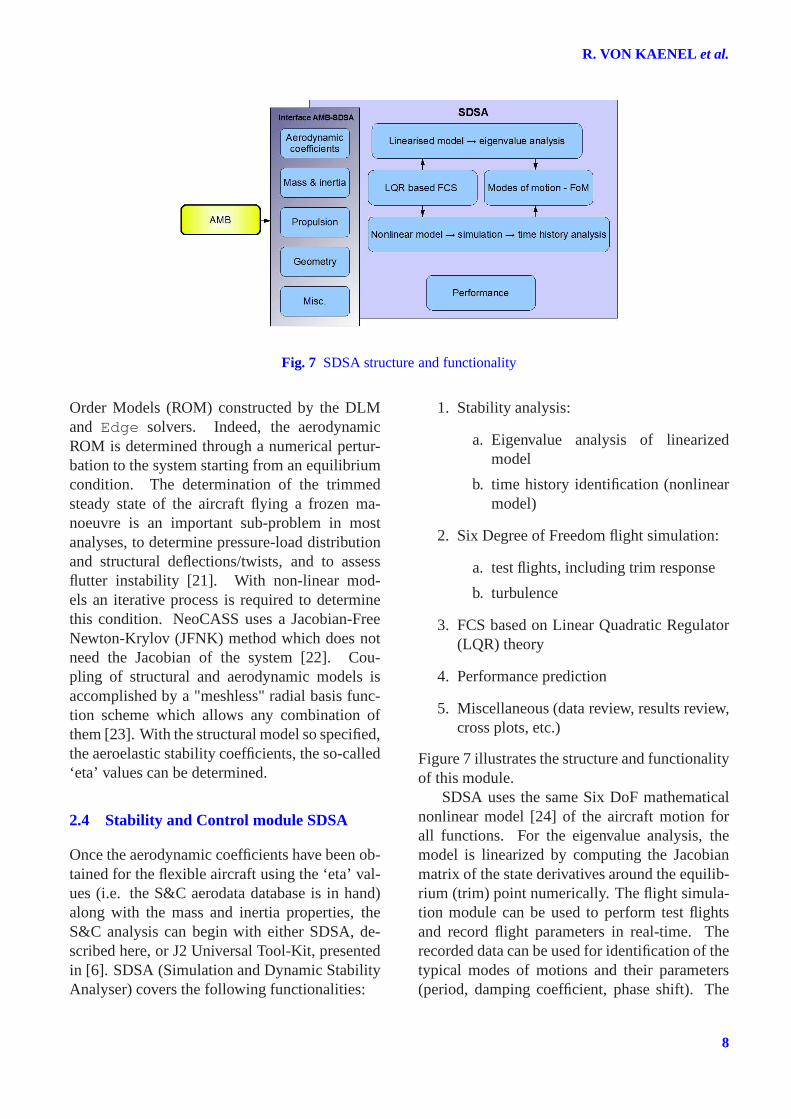
Fig. 7 SDSA structure and functionality
Order Models (ROM) constructed by the DLMand Edge solvers. Indeed, the aerodynamicROM is determined through a numerical pertur-bation to the system starting from an equilibriumcondition. The determination of the trimmedsteady state of the aircraft flying a frozen ma-noeuvre is an important sub-problem in mostanalyses, to determine pressure-load distributionand structural deflections/twists, and to assessflutter instability [21]. With non-linear mod-els an iterative process is required to determinethis condition. NeoCASS uses a Jacobian-FreeNewton-Krylov (JFNK) method which does notneed the Jacobian of the system [22]. Cou-pling of structural and aerodynamic models isaccomplished by a "meshless" radial basis func-tion scheme which allows any combination ofthem [23]. With the structural model so specified,the aeroelastic stability coefficients, the so-called‘eta’ values can be determined.
2.4 Stability and Control module SDSA
Once the aerodynamic coefficients have been ob-tained for the flexible aircraft using the ‘eta’ val-ues (i.e. the S&C aerodata database is in hand)along with the mass and inertia properties, theS&C analysis can begin with either SDSA, de-scribed here, or J2 Universal Tool-Kit, presentedin [6]. SDSA (Simulation and Dynamic StabilityAnalyser) covers the following functionalities:
1. Stability analysis:
a. Eigenvalue analysis of linearizedmodel
b. time history identification (nonlinearmodel)
2. Six Degree of Freedom flight simulation:
a. test flights, including trim response
b. turbulence
3. FCS based on Linear Quadratic Regulator(LQR) theory
4. Performance prediction
5. Miscellaneous (data review, results review,cross plots, etc.)
Figure 7 illustrates the structure and functionalityof this module.
SDSA uses the same Six DoF mathematicalnonlinear model [24] of the aircraft motion forall functions. For the eigenvalue analysis, themodel is linearized by computing the Jacobianmatrix of the state derivatives around the equilib-rium (trim) point numerically. The flight simula-tion module can be used to perform test flightsand record flight parameters in real-time. Therecorded data can be used for identification of thetypical modes of motions and their parameters(period, damping coefficient, phase shift). The
8
CEASIOM: Simulating Stability & Control with CFD/CSM in Air craft Conceptual Design
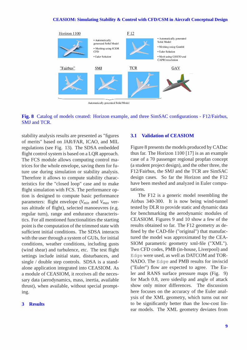
Fig. 8 Catalog of models created: Horizon example, and three SimSAC configurations - F12/Fairbus,SMJ and TCR.
stability analysis results are presented as "figuresof merits" based on JAR/FAR, ICAO, and MILregulations (see Fig. 13). The SDSA embeddedflight control system is based on a LQR approach.The FCS module allows computing control ma-trices for the whole envelope, saving them for fu-ture use during simulation or stability analysis.Therefore it allows to compute stability charac-teristics for the "closed loop" case and to makeflight simulation with FCS. The performance op-tion is designed to compute basic performanceparameters: flight envelope (Vmin andVmax ver-sus altitude of flight), selected manoeuvres (e.g.regular turn), range and endurance characteris-tics. For all mentioned functionalities the startingpoint is the computation of the trimmed state withsufficient initial conditions. The SDSA interactswith the user through a system of GUIs, for initialconditions, weather conditions, including gusts(wind shear) and turbulence, etc. The test flightsettings include initial state, disturbances, andsingle / double step controls. SDSA is a stand-alone application integrated into CEASIOM. Asa module of CEASIOM, it receives all the neces-sary data (aerodynamics, mass, inertia, availablethrust), when available, without special prompt-ing.
3 Results
3.1 Validation of CEASIOM
Figure 8 presents the models produced by CADacthus far. The Horizon 1100 [17] is as an examplecase of a 70 passenger regional propfan concept(a student project design), and the other three, theF12/Fairbus, the SMJ and the TCR are SimSACdesign cases. So far the Horizon and the F12have been meshed and analyzed in Euler compu-tations.
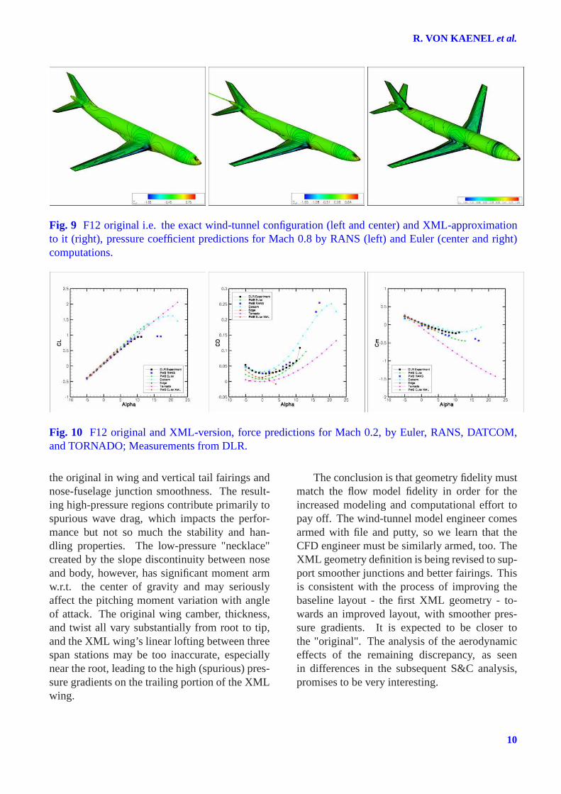
The F12 is a generic model resembling theAirbus 340-300. It is now being wind-tunneltested by DLR to provide static and dynamic datafor benchmarking the aerodynamic modules ofCEASIOM. Figures 9 and 10 show a few of theresults obtained so far. The F12 geometry as de-fined by the CAD-file ("original") that manufac-tured the model was approximated by the CEA-SIOM parametric geometry xml-file ("XML").Two CFD codes, PMB (in-house, Liverpool) andEdgewere used, as well as DATCOM and TOR-NADO. TheEdge and PMB results for inviscid("Euler") flow are expected to agree. The Eu-ler and RANS surface pressure maps (Fig. 9)for Mach 0.8, zero sideslip and angle of attackshow only minor differences. The discussionhere focuses on the accuracy of the Euler anal-ysis of the XML geometry, which turns outnotto be significantly better than the low-cost lin-ear models. The XML geometry deviates from
9
R. VON KAENEL et al.
Fig. 9 F12 original i.e. the exact wind-tunnel configuration (leftand center) and XML-approximationto it (right), pressure coefficient predictions for Mach 0.8by RANS (left) and Euler (center and right)computations.
Fig. 10 F12 original and XML-version, force predictions for Mach 0.2, by Euler, RANS, DATCOM,and TORNADO; Measurements from DLR.
the original in wing and vertical tail fairings andnose-fuselage junction smoothness. The result-ing high-pressure regions contribute primarily tospurious wave drag, which impacts the perfor-mance but not so much the stability and han-dling properties. The low-pressure "necklace"created by the slope discontinuity between noseand body, however, has significant moment armw.r.t. the center of gravity and may seriouslyaffect the pitching moment variation with angleof attack. The original wing camber, thickness,and twist all vary substantially from root to tip,and the XML wing’s linear lofting between threespan stations may be too inaccurate, especiallynear the root, leading to the high (spurious) pres-sure gradients on the trailing portion of the XMLwing.
The conclusion is that geometry fidelity mustmatch the flow model fidelity in order for theincreased modeling and computational effort topay off. The wind-tunnel model engineer comesarmed with file and putty, so we learn that theCFD engineer must be similarly armed, too. TheXML geometry definition is being revised to sup-port smoother junctions and better fairings. Thisis consistent with the process of improving thebaseline layout - the first XML geometry - to-wards an improved layout, with smoother pres-sure gradients. It is expected to be closer tothe "original". The analysis of the aerodynamiceffects of the remaining discrepancy, as seenin differences in the subsequent S&C analysis,promises to be very interesting.
10

CEASIOM: Simulating Stability & Control with CFD/CSM in Air craft Conceptual Design
Fig. 11 TCR analysis by AMB with DATCOM (red) and TORNADO (blue). Upper left, 3-view, TOR-NADO idealization, moment reference point, CoG, and MAC; Lower: Yawing moment, and Pitching-moment coefficients; Upper right, Lift coefficient for elevator deflected + and - 20 deg.
3.2 Design case: Transonic cruiser TCR
CEASIOM is being applied to a selection of de-sign exercises of two types: 1) new unconven-tional configurations, and, 2) improved design ofexisting configurations.In category 1, the design mission of the transoniccruiser (TCR) specifies a commercial transportcarrying 200 passengers with a range of 5500nm at a cruise speed ofM = 0.97. To begin thisstudy, the TCR has been analyzed for low-speedaerodynamics by TORNADO and DATCOM, asshown in Fig. 11. Studied here is the meshablemodel of the baseline configuration created bySAAB and shown in Fig. 8. This baseline wassuspected to have problems with trim and eleva-tor effectiveness. In category 2, the F12 is an ex-isting wind-tunnel model, and the design task isto protract it into a transport aircraft with roughlythe specification of the Airbus 340-300. Sincethe F12 is a wind-tunnel model without enginesor control surfaces, the task involves scaling theconfiguration, mounting engines and sizing thecontrol surfaces. The resulting baseline configu-ration, dubbed the Fairbus, is shown in Fig. 8.
The following describes the work done todate using CEASIOM for the analysis of the TCRbaseline configuration, considered as a rigid air-frame. First the aero coefficients are computedwith AMB-CFD, then the structural model for themass, center of gravity, and inertias which spec-ify the aircraft are constructed with NeoCASSand finally, S&C SDSA analyzes the flight dy-namics.
3.2.1 Aerodynamics
The lift coefficient for elevator up and down, (up-per right in Fig. 11), shows that DATCOM pre-dicts slightly smaller elevator effectiveness, witha δCL/δe of about 0.13 vs. 0.16 per rad. Theinterpretation is as follows: As seen in Fig. 11,the TORNADO panel, TORNADO assumes theelevator to extend from root to tip, as specifiedby the control-surface definitions in the geome-try XML file, while DATCOM considers the ac-tual elevator span value which is smaller. Thislack of precision in defining the control surfaceneeds to be remedied by enriching the input data.Notice that DATCOM predicts largerδCL/δα.
11

R. VON KAENEL et al.
Fig. 12 Center of gravity excursion predicted bythe structural model of NeoCASS as function ofpayload and fuel.
Reasons for this are that: 1) DATCOM considersthe part of the wing inside the fuselage, and 2)DATCOM methods for a wing+Body+Tail con-figuration are limited to a straight tapered wing(see DATCOM Manual). For cranked wings, av-erage values for sweep angle and dihedral anglesare used. Usually, this estimation method over-estimates the lift compared with TORNADO us-ing the actual wing geometry. The correspondingeffect is seen in the pitching moment vs. AoA,lower right: the DATCOM slope is steeper formuch the same reason.
3.2.2 Weights and balances
The fuel burn en route changes weights and bal-ances, as does different payloads - here synony-mous with different number of passengers. TheGUESS module of NeoCASS produces estimatesof structural weights and stiffnesses, when givena few parameters which determine the technol-ogy. Also, placement and size of fuel tanks isindicated by a few parameters. The carpet plot inFig. 12 shows the position of the centre of gravityin the standard geometry coordinates (origin atnose,x positive rearwards, andz up) for 0 to 200passengers (incl. luggage), and fuel from emptyto full.
3.2.3 S&C Analysis
Figure 13 presents selected results from SDSAfor the stability analysis of the TCR baseline con-figuration. The first graph shows phugoid resultsreferred to ICAO recommendations. The char-acteristics of the phugoid are acceptable and areplaced on the border between "satisfactory" and"acceptable for emergency conditions" accord-ing to ICAO. The second graph presents shortperiod characteristics referred to ICAO recom-mendations too. They are mostly below the line,where the pilot rating is equal to 3.5: lateral sta-bility characteristics are not so good as the lon-gitudinal ones. The Dutch roll mode is stable,however not enough for high altitude flights, ac-cording to the MIL-F-8785C regulations. Rolland spiral modes are partly coupled but stable,with over 150s period and time-to-half-amplitudeabout 20s. The lateral characteristics should beimproved, e.g by increasing the vertical tail areaor it’s arm, or by decreasing the main wing di-hedral. The center of gravity position could beshifted forward, but this changes also the longi-tudinal characteristics, so it must be done verycarefully.
4 Concluding Remarks and Future Work
The paper has presented the status of CEASIOMand its application in design at the halfway markin the three-year SimSAC Project. Work contin-ues in the next eighteen months when:
• CADac will prescribe the control surfacesin the meshable CAD model and automatefurther the mesh generation process
• A geometry builder with visual feedbackwill be set up
• NeoCASS will produce the ’eta’ aeroe-lastic coefficients and determine flutterboundaries
• A seamless interface to the J2 Universalsoftware will be in place
12

CEASIOM: Simulating Stability & Control with CFD/CSM in Air craft Conceptual Design
Fig. 13 SDSA predicted characteristics: a) phugoid mode, b) short-period and c) Dutch roll mode forthe TCR configuration.
• The FCSDT elastic TCR configuration willbe analyzed with Euler CFD solutions forhigh-speed flight
The design exercises will also continue withtier I+ and tier II analysis and configuration re-finement of the baseline designs of TCR, SMJ,Fairbus and GAV concepts.
5 Acknowledgments
The financial support by the European Commis-sion through co-funding of the FP6 project Sim-SAC is gratefully acknowledged.
References
[1] Vos J. B., Rizzi A., Darracq D. and Hirschel E.H. Navier-Stokes solvers in European aircraftdesign, Progress in Aerospace Sciences, No. 38,2002.
[2] Isikveren A. Quasi-Analytical Modeling andOptimisation Techniques for Transport AircraftDesign. Doctoral Thesis Report 2002-13, De-partment of Aeronautics, Royal Institute ofTechnology, Stockholm.
[3] http://www.mathworks.com
[4] Raymer D.P.Aircraft Design: A Conceptual Ap-proach. 4th ed, AIAA Education Series, Reston,VA. 2006.
[5] Wakayama, S.Engineering Flight Simulator -User Guide, Desktop Aeronautics, Palo Alto,CA, 1995.
[6] Jeffrey J. Cost benefits of aerodynamic datageneration techniques for aircraft stability andcontrol analysis using the J2 Universal Tool-Kit, SAE Paper 08WATC-01-2254, Aug 2008.
[7] Simos D.Project Interactive Analysis and Opti-mization - PIANO version 3.8. Lissys Limited,1990-2001.
[8] Roskam J.Airplane Design. Part I through VIII,Roskam Aviation and Engineering Corporation,Kansas, USA, 1990.
[9] De Filippo R.ACSYNT User’s Guide. NorthropAircraft, 1983.
[10] Bérard A., Rizzi A. and Isikveren A.T.CADac: a New Geometry Construction Toolfor Aerospace Vehicle Pre-Design and Concep-tual Design, AIAA, 26th Applied Aerodynam-ics Conference Honolulu, Hawaii, USA, August18-21, 2008.
[11] Haimes R. CAPRI: Computational AnalysisPRogramming Interface: A Solid ModelingBased Infra-structure for Engineering Analysisand Design. Massachusetts Institute of Technol-ogy, Cambridge, USA
[12] Tang, C.Y., Gee, K. and Lawrence, S.Gener-ation of Aerodynamic Data using a Design ofExperiment and Data Fusion Approach, 43rdAIAA Aerospace Sciences meeting, (Reno,NV), 2005, AIAA-2005-1137.
[13] Ghoreyshi, M., Badcock, K.J. and Woodgate,M. Integration of Multi-Fidelity Methods forGenerating an Aerodynamic Model for FlightSimulation, 46th Aerospace Sciences meeting,(Reno, NV), 2008, AIAA-2008-197.
[14] Laurenceau, J. and Sagaut, P.Building Effi-cient Response Surfaces of Aerodynamic Func-tions with Kriging and Cokriging, AIAA Jour-nal, Vol. 46, No. 2, pp. 498–507, 2008.
[15] Bérard A., Rizzi A. and Isikveren A.T.Develop-ment and implementation of aerodynamic anal-ysis methods for aircraft conceptual design, in
13

R. VON KAENEL et al.
CASI AERO 2007, (Toronto, Canada), April24-26, 2007.
[16] Eliasson P.A Navier-Stokes Solver for Unstruc-tured Grids., FOI/FFA report FOI-R-0298-SE,FOI, Stockholm, Sweden, 2001.
[17] Bérard A., Alwan H. and McKechnie G.Aero-dynamic Report on the Horizon 1100 Concept.Royal Institute of Technology, Stockholm, Swe-den, 2005.
[18] Bérard A., Rizzi A., Cavagna L., Ricci S., andRiccobene L.Development and Validation ofa Next-Generation Conceptual Aero-StructuralSizing Suite, ICAS-International Council for theAeronautical Sciences September 14-19, 2008,Anchorage, Alaska, USA.
[19] Cavagna L., Ricci S., Riccobene L. B, érard A.,and Rizzi A.,A Fast MDO tool for Aeroelas-tic Optimization in Aircraft Conceptual Design,12th AIAA/ISSMO Multidisciplinary Analysisand Optimization Conference 10-12 Sep 2008,Victoria, British Columbia, Canada
[20] Fisher C. and Arena A.On the transpirationmethod for efficient aeroelastic analysis usingan Euler solver, in Proceedings of the AIAA At-mospheric Flight Mechanics Conference, (SanDiego, CA), July 29-31, 1996.
[21] Cavagna L., Quaranta G. and Mantegazza P.Application of Navier-Stokes simulations foraeroelastic assessment in transonic regime,Computers & Structures, Fourth MIT Confer-ence on Computational Fluid and Solid Me-chanics, vol. 85, no. 11-14, 2007.
[22] Cavagna L., Quaranta G., Mantegazza P. andMarchetti D.Aeroelastic assessment of the freeflying aircraft in transonic regime, in Interna-tional Forum on Aeroelasticity and StructuralDynamics IFASD-2007, Stockholm, Sweden,June 18-20, 2007.
[23] Quaranta G., Masarati P. and Mantegazza P.A conservative mesh-free approach for fluid-structure interface problems, in InternationalConference on Computational Methods forCoupled Problems in Science and Engineering(M. Papadrakakis, E. Oñate, and B. Schrefler,eds.), (Santorini, Greece), CIMNE, 2005.
[24] Goetzendorf-Grabowski T.Modelling of theaircraft motion - theory and application, inOptimalsteuerungsprobleme von Hyperschall-
Flugzeugsystemen, Workshop des Sonder-forschungsbereichs 255, Greifswald-München,1997.
6 Copyright Statement
The authors confirm that they, and/or their company orinstitution, hold copyright on all of the original mate-rial included in their paper. They also confirm theyhave obtained permission, from the copyright holderof any third party material included in their paper, topublish it as part of their paper. The authors grant fullpermission for the publication and distribution of theirpaper as part of the ICAS2008 proceedings or as indi-vidual off-prints from the proceedings.
14