Embed Size (px)
Citation preview
Instruction Bulletin
© 2011 Schneider Electric. All Rights Reserved.
63249-420-367A1 02/2012
Ceiling-Mounted Line Voltage Occupancy Sensor SLSCLP1000, SLSCLU2000, SLSCLD2000
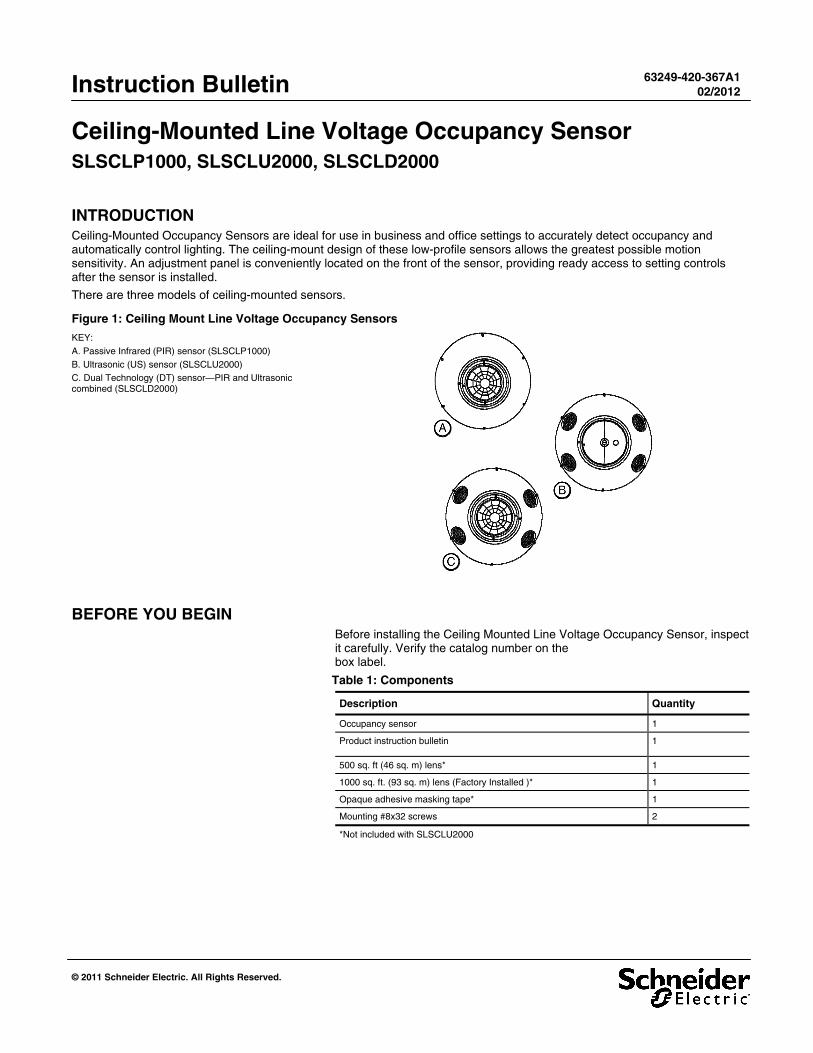
INTRODUCTION Ceiling-Mounted Occupancy Sensors are ideal for use in business and office settings to accurately detect occupancy and automatically control lighting. The ceiling-mount design of these low-profile sensors allows the greatest possible motion sensitivity. An adjustment panel is conveniently located on the front of the sensor, providing ready access to setting controls after the sensor is installed.
There are three models of ceiling-mounted sensors.
Figure 1: Ceiling Mount Line Voltage Occupancy Sensors
KEY: A. Passive Infrared (PIR) sensor (SLSCLP1000) B. Ultrasonic (US) sensor (SLSCLU2000) C. Dual Technology (DT) sensor—PIR and Ultrasonic combined (SLSCLD2000)
BEFORE YOU BEGIN Before installing the Ceiling Mounted Line Voltage Occupancy Sensor, inspect it carefully. Verify the catalog number on the box label.
Table 1: Components
Description Quantity
Occupancy sensor 1
Product instruction bulletin 1
500 sq. ft (46 sq. m) lens* 1
1000 sq. ft. (93 sq. m) lens (Factory Installed )* 1
Opaque adhesive masking tape* 1
Mounting #8x32 screws 2
*Not included with SLSCLU2000

Ceiling-Mounted Line Voltage Occupancy Sensor 63249-420-367A1 Instruction Bulletin 02/2012
2 © 2011 Schneider Electric. All Rights Reserved.
FEATURES Table 2: Ceiling Mounted Line Voltage Occupancy Sensor Features
Description PIR
(SLSCLP1000)
Ultrasonic
(SLSCLU2000)
Dual Technology
(SLSCLD2000)
Coverage area 1000 sq. ft. 2000 sq. ft. 2000 sq. ft.
Field of view 360°
Ambient light level sensing 0.5-250 foot candles
Adjustable time delay 15 sec.-30 min.
Walk through mode
Adaptive PIR x
Adaptive timing
Auto/manual light level sensing
Operation Mode x x
Adjustable sensitivity 50-500 sq. ft. lens 100-1000 sq. ft. lens (10-100% of max. coverage)
200-2000 sq. ft. (10-100% of max. coverage)
PIR: 50-500 sq. ft. lens 100-1000 sq. ft. lens (10-100% of max. coverage)
Ultrasonic: 200-2000 sq. ft. (10-100% of max. coverage)
LED motion indicators 1 (red) 1 (red) 2 (red/green)
SAFETY PRECAUTIONS This section contains important safety precautions that must be followed before attempting to install or maintain electrical equipment. Carefully read and follow the safety precautions below.
HAZARD OF ELECTRIC SHOCK, EXPLOSION, OR ARC FLASH
Apply appropriate personal protective equipment (PPE) and follow safe electrical work practices. See NFPA 70E.
This equipment must be installed and serviced by qualified electrical personnel.
Turn off all electrical power supplying this equipment before working on or inside the equipment.
Always use a properly rated voltage sensing device to confirm that power is off.
Replace all devices, doors, and covers before turning on power to this equipment.
Failure to follow these instructions will result in death or serious injury.
63249-420-367A1 Ceiling-Mounted Line Voltage Occupancy Sensor 02/2012 Instruction Bulletin
© 2011 Schneider Electric. All Rights Reserved. 3
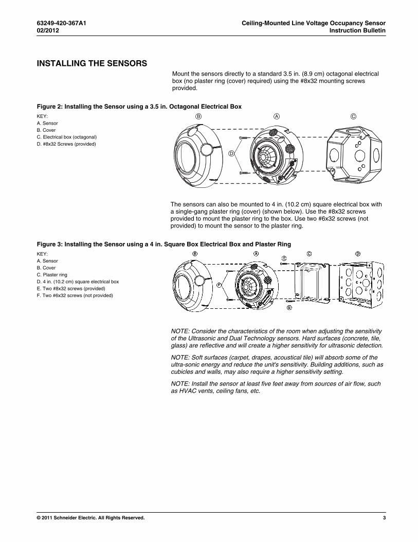
INSTALLING THE SENSORS Mount the sensors directly to a standard 3.5 in. (8.9 cm) octagonal electrical box (no plaster ring (cover) required) using the #8x32 mounting screws provided.
Figure 2: Installing the Sensor using a 3.5 in. Octagonal Electrical Box
KEY: A. Sensor B. Cover C. Electrical box (octagonal) D. #8x32 Screws (provided)
AB C
D
The sensors can also be mounted to 4 in. (10.2 cm) square electrical box with a single-gang plaster ring (cover) (shown below). Use the #8x32 screws provided to mount the plaster ring to the box. Use two #6x32 screws (not provided) to mount the sensor to the plaster ring.
Figure 3: Installing the Sensor using a 4 in. Square Box Electrical Box and Plaster Ring
KEY: A. Sensor B. Cover C. Plaster ring D. 4 in. (10.2 cm) square electrical box E. Two #8x32 screws (provided) F. Two #6x32 screws (not provided)
NOTE: Consider the characteristics of the room when adjusting the sensitivity of the Ultrasonic and Dual Technology sensors. Hard surfaces (concrete, tile, glass) are reflective and will create a higher sensitivity for ultrasonic detection.
NOTE: Soft surfaces (carpet, drapes, acoustical tile) will absorb some of the ultra-sonic energy and reduce the unit's sensitivity. Building additions, such as cubicles and walls, may also require a higher sensitivity setting.
NOTE: Install the sensor at least five feet away from sources of air flow, such as HVAC vents, ceiling fans, etc.
Ceiling-Mounted Line Voltage Occupancy Sensor 63249-420-367A1 Instruction Bulletin 02/2012
4 © 2011 Schneider Electric. All Rights Reserved.
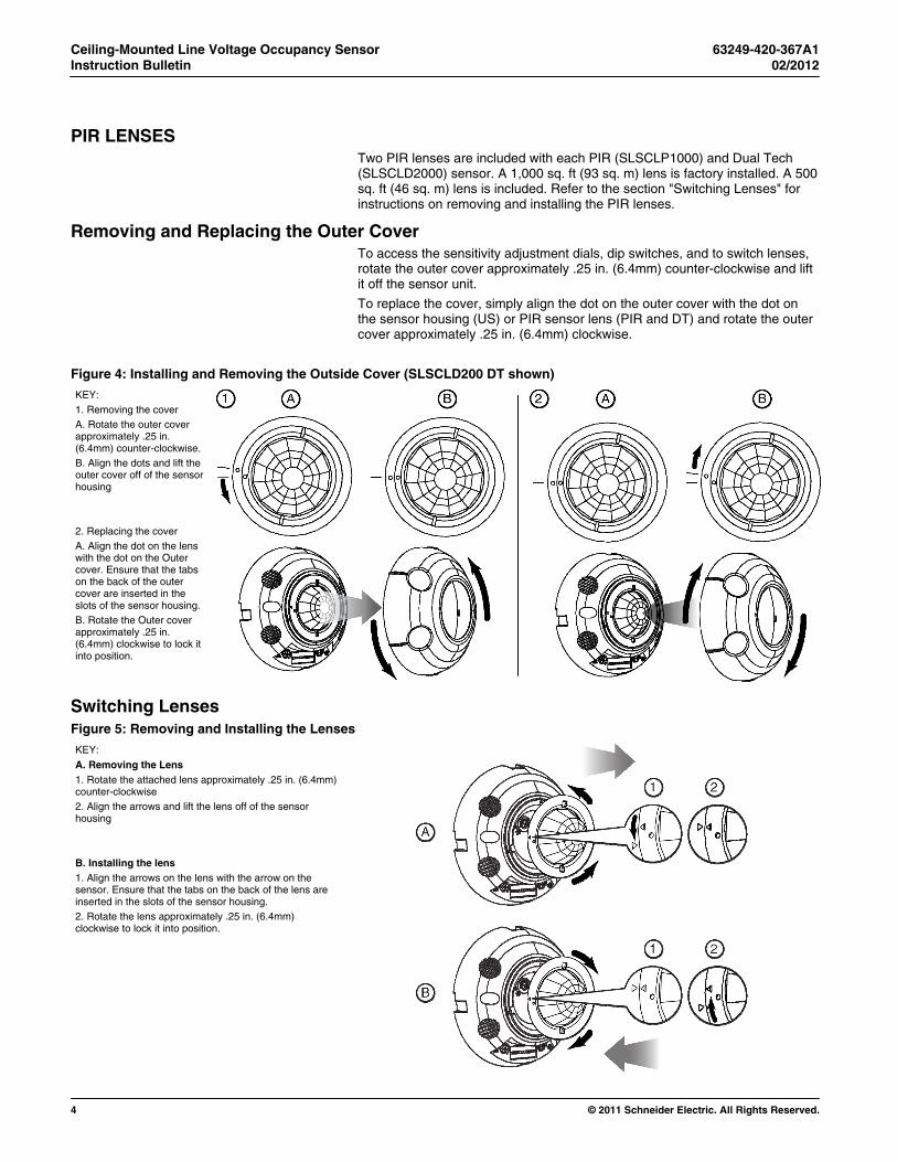
PIR LENSES Two PIR lenses are included with each PIR (SLSCLP1000) and Dual Tech (SLSCLD2000) sensor. A 1,000 sq. ft (93 sq. m) lens is factory installed. A 500 sq. ft (46 sq. m) lens is included. Refer to the section "Switching Lenses" for instructions on removing and installing the PIR lenses.
Removing and Replacing the Outer Cover To access the sensitivity adjustment dials, dip switches, and to switch lenses, rotate the outer cover approximately .25 in. (6.4mm) counter-clockwise and lift it off the sensor unit.
To replace the cover, simply align the dot on the outer cover with the dot on the sensor housing (US) or PIR sensor lens (PIR and DT) and rotate the outer cover approximately .25 in. (6.4mm) clockwise.
Figure 4: Installing and Removing the Outside Cover (SLSCLD200 DT shown)
KEY: 1. Removing the cover A. Rotate the outer cover approximately .25 in. (6.4mm) counter-clockwise. B. Align the dots and lift the outer cover off of the sensor housing 2. Replacing the cover A. Align the dot on the lens with the dot on the Outer cover. Ensure that the tabs on the back of the outer cover are inserted in the slots of the sensor housing. B. Rotate the Outer cover approximately .25 in. (6.4mm) clockwise to lock it into position.
Switching Lenses Figure 5: Removing and Installing the Lenses
KEY:
A. Removing the Lens 1. Rotate the attached lens approximately .25 in. (6.4mm) counter-clockwise 2. Align the arrows and lift the lens off of the sensor housing
B. Installing the lens 1. Align the arrows on the lens with the arrow on the sensor. Ensure that the tabs on the back of the lens are inserted in the slots of the sensor housing. 2. Rotate the lens approximately .25 in. (6.4mm) clockwise to lock it into position.
63249-420-367A1 Ceiling-Mounted Line Voltage Occupancy Sensor 02/2012 Instruction Bulletin
© 2011 Schneider Electric. All Rights Reserved. 5
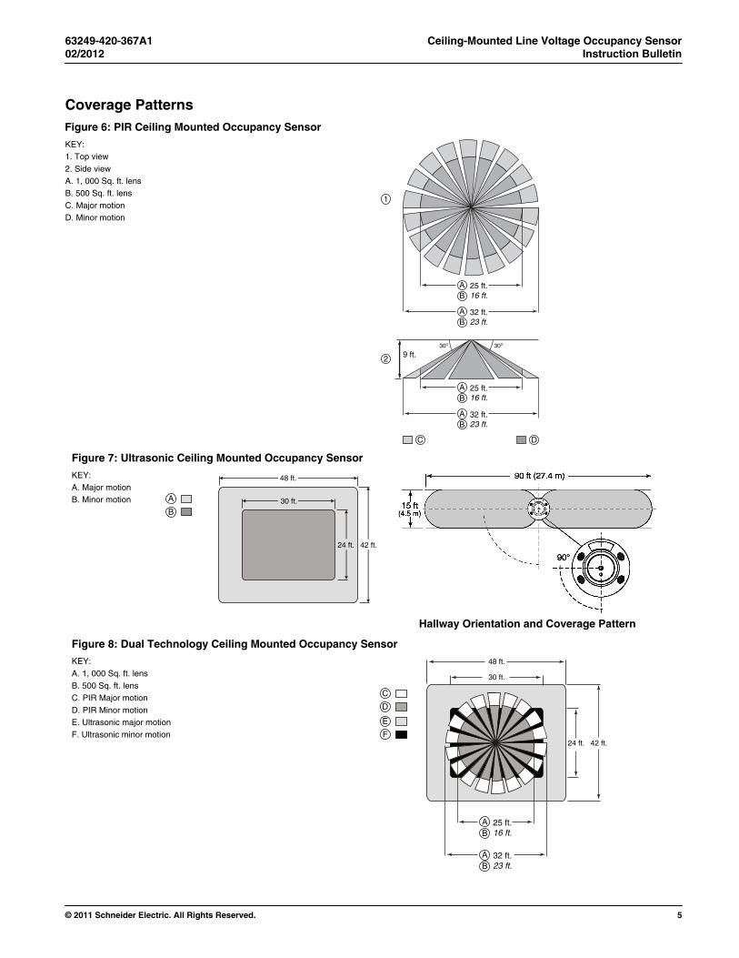
Coverage Patterns Figure 6: PIR Ceiling Mounted Occupancy Sensor
KEY: 1. Top view 2. Side view A. 1, 000 Sq. ft. lens B. 500 Sq. ft. lens C. Major motion D. Minor motion
AB
1
2 9 ft.
25 ft.16 ft.
AB
C D
32 ft.23 ft.
AB
25 ft.16 ft.
AB
32 ft.23 ft.
Figure 7: Ultrasonic Ceiling Mounted Occupancy Sensor
KEY: A. Major motion B. Minor motion
Hallway Orientation and Coverage Pattern
Figure 8: Dual Technology Ceiling Mounted Occupancy Sensor
KEY: A. 1, 000 Sq. ft. lens B. 500 Sq. ft. lens C. PIR Major motion D. PIR Minor motion E. Ultrasonic major motion F. Ultrasonic minor motion
48 ft.
42 ft.24 ft.
30 ft.
E
F
C
D
AB
25 ft.16 ft.
AB
32 ft.23 ft.
48 ft.
42 ft.24 ft.
30 ft.A
B
Ceiling-Mounted Line Voltage Occupancy Sensor 63249-420-367A1 Instruction Bulletin 02/2012
6 © 2011 Schneider Electric. All Rights Reserved.
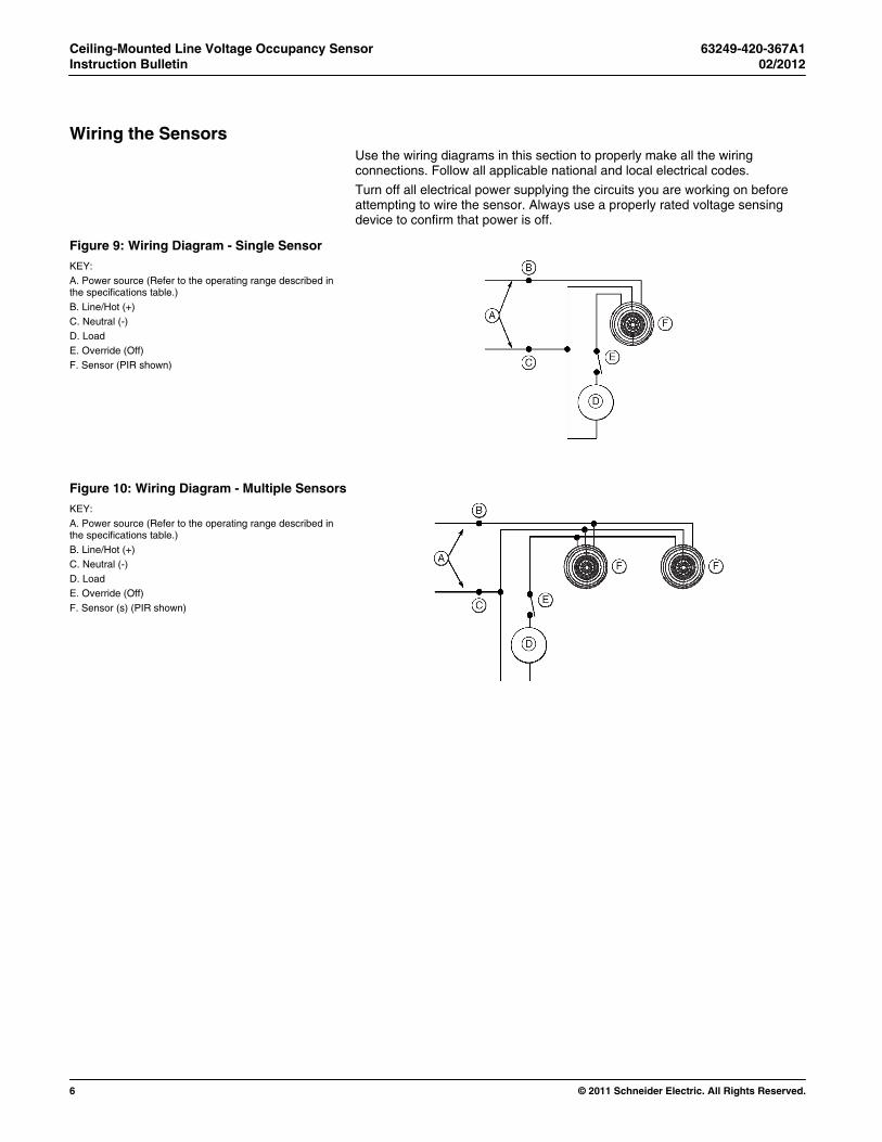
Wiring the Sensors Use the wiring diagrams in this section to properly make all the wiring connections. Follow all applicable national and local electrical codes.
Turn off all electrical power supplying the circuits you are working on before attempting to wire the sensor. Always use a properly rated voltage sensing device to confirm that power is off.
Figure 9: Wiring Diagram - Single Sensor
KEY: A. Power source (Refer to the operating range described in the specifications table.) B. Line/Hot (+) C. Neutral (-) D. Load E. Override (Off) F. Sensor (PIR shown)
Figure 10: Wiring Diagram - Multiple Sensors
KEY: A. Power source (Refer to the operating range described in the specifications table.) B. Line/Hot (+) C. Neutral (-) D. Load E. Override (Off) F. Sensor (s) (PIR shown)
63249-420-367A1 Ceiling-Mounted Line Voltage Occupancy Sensor 02/2012 Instruction Bulletin
© 2011 Schneider Electric. All Rights Reserved. 7
OPERATION 1. Restore power to the circuit.
2. Whenever motion is detected the LED(s) on the sensor housing will briefly flash on and the lights will turn or remain on.
NOTE: When first installed, the sensor may have to warm up for a few minutes before it is fully operational.
3. Set the Time Delay to the Test setting.
4. Vacate the room until the lights turn off.
5. Re-enter the room. Lights should turn on immediately. If lights do not turn on immediately, verify correct sensor wiring.
6. Once the sensor is operational, adjust the settings.
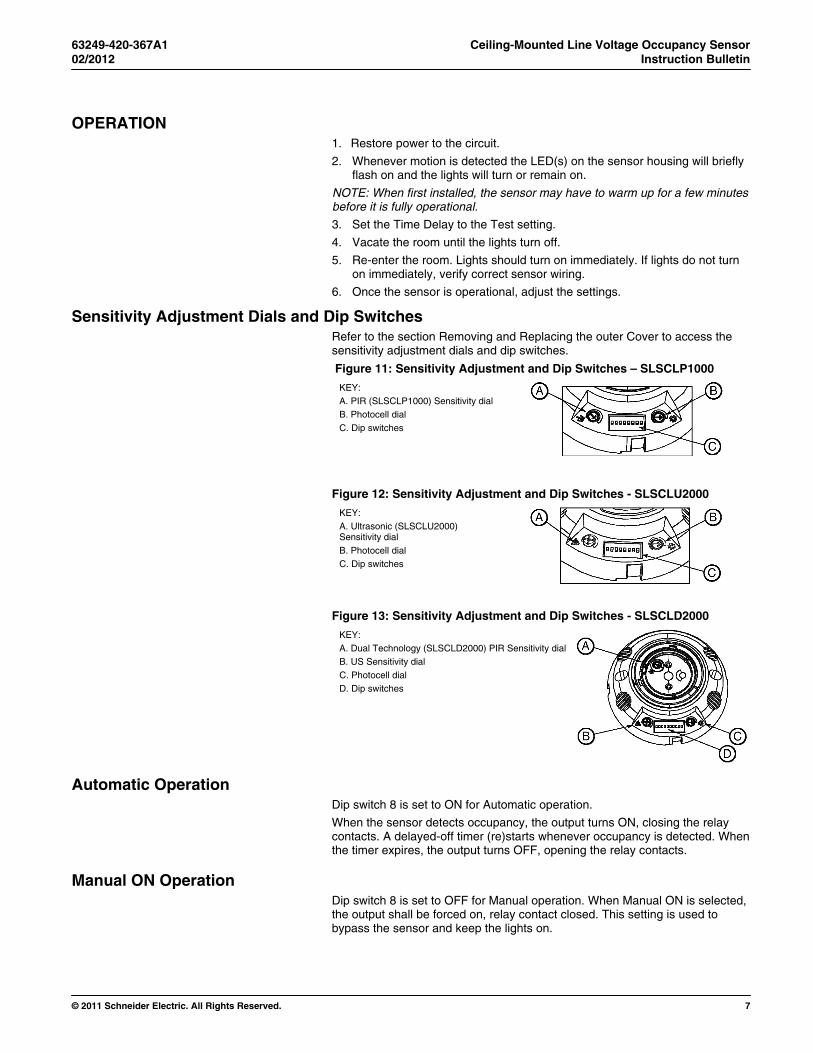
Sensitivity Adjustment Dials and Dip Switches Refer to the section Removing and Replacing the outer Cover to access the sensitivity adjustment dials and dip switches.
Figure 11: Sensitivity Adjustment and Dip Switches – SLSCLP1000
KEY: A. PIR (SLSCLP1000) Sensitivity dial B. Photocell dial C. Dip switches
Figure 12: Sensitivity Adjustment and Dip Switches - SLSCLU2000
KEY: A. Ultrasonic (SLSCLU2000) Sensitivity dial B. Photocell dial C. Dip switches
Figure 13: Sensitivity Adjustment and Dip Switches - SLSCLD2000
KEY: A. Dual Technology (SLSCLD2000) PIR Sensitivity dialB. US Sensitivity dial C. Photocell dial D. Dip switches
Automatic Operation Dip switch 8 is set to ON for Automatic operation.
When the sensor detects occupancy, the output turns ON, closing the relay contacts. A delayed-off timer (re)starts whenever occupancy is detected. When the timer expires, the output turns OFF, opening the relay contacts.
Manual ON Operation Dip switch 8 is set to OFF for Manual operation. When Manual ON is selected, the output shall be forced on, relay contact closed. This setting is used to bypass the sensor and keep the lights on.
Ceiling-Mounted Line Voltage Occupancy Sensor 63249-420-367A1 Instruction Bulletin 02/2012
8 © 2011 Schneider Electric. All Rights Reserved.
Sensor Adjustment Follow the guidelines and refer to the diagrams below to properly adjust the sensor or switches lenses for proper operation.
Sensitivity Adjustment The sensor's sensitivity is adjustable from 10% to 100% of maximum coverage to increase or decrease the distance and movement required to trigger the sensor. Turning the adjustment dial fully counter-clockwise selects the minimum coverage sensitivity. Turning the adjustment pot fully clockwise selects the maximum coverage sensitivity. The factory default setting is the maximum coverage position (100%).
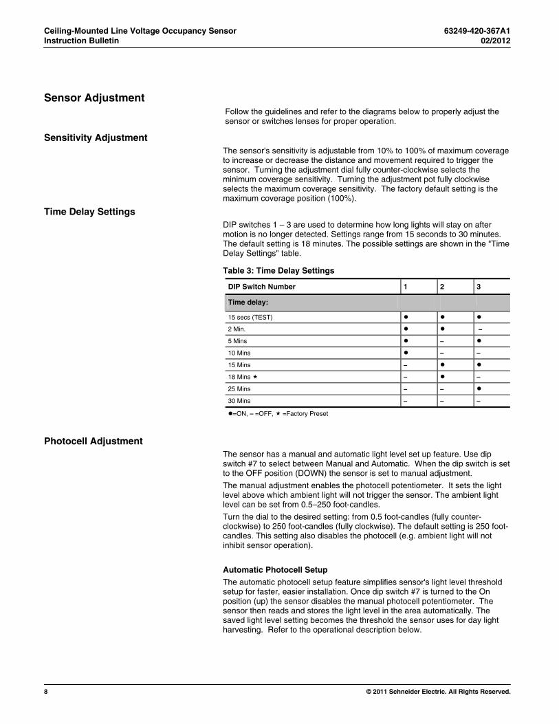
Time Delay Settings DIP switches 1 – 3 are used to determine how long lights will stay on after motion is no longer detected. Settings range from 15 seconds to 30 minutes. The default setting is 18 minutes. The possible settings are shown in the "Time Delay Settings" table.
Table 3: Time Delay Settings
DIP Switch Number 1 2 3
Time delay:
15 secs (TEST)
2 Min. –
5 Mins –
10 Mins – –
15 Mins –
18 Mins – –
25 Mins – –
30 Mins – – –
=ON, – =OFF, =Factory Preset
Photocell Adjustment The sensor has a manual and automatic light level set up feature. Use dip switch #7 to select between Manual and Automatic. When the dip switch is set to the OFF position (DOWN) the sensor is set to manual adjustment.
The manual adjustment enables the photocell potentiometer. It sets the light level above which ambient light will not trigger the sensor. The ambient light level can be set from 0.5–250 foot-candles.
Turn the dial to the desired setting: from 0.5 foot-candles (fully counter-clockwise) to 250 foot-candles (fully clockwise). The default setting is 250 foot-candles. This setting also disables the photocell (e.g. ambient light will not inhibit sensor operation).
Automatic Photocell Setup
The automatic photocell setup feature simplifies sensor's light level threshold setup for faster, easier installation. Once dip switch #7 is turned to the On position (up) the sensor disables the manual photocell potentiometer. The sensor then reads and stores the light level in the area automatically. The saved light level setting becomes the threshold the sensor uses for day light harvesting. Refer to the operational description below.
63249-420-367A1 Ceiling-Mounted Line Voltage Occupancy Sensor 02/2012 Instruction Bulletin
© 2011 Schneider Electric. All Rights Reserved. 9
Move dip switch #7 to ON (UP) to start the automatic light level setup process.
The sensor turns on the load, ignoring any occupancy detections. The sensor will sit idle for 10 seconds, flashing the red LEDs.
NOTE: The 10 seconds gives the installer time to move away from the sensor, thus preventing shadowing or ambient light interference. During this time the lights will remain on.
After the 10 seconds has expired, the sensor takes a measurement of the light level in the area with the lighting on.
The sensor saves the light level measurement into memory. From this point forward this saved light level reading is the light level threshold for the sensor.
The red LED flashes rapidly for 3 seconds to confirm the sensor has stored the new light level.
Once the light level threshold is saved the setup process is complete. The sensor return to it's previous operating mode.
To turn off the automatic light level feature, turn dip switch #7 to OFF (DOWN). This returns the sensor to manual photocell adjustment operation.
Resetting the Light Level To reset the light level threshold, Toggle dip switch #7 from OFF (DOWN) to ON (UP). This will force the sensor receive and store a new light level reading.
Modes of Operation Dual Technology Sensor Settings
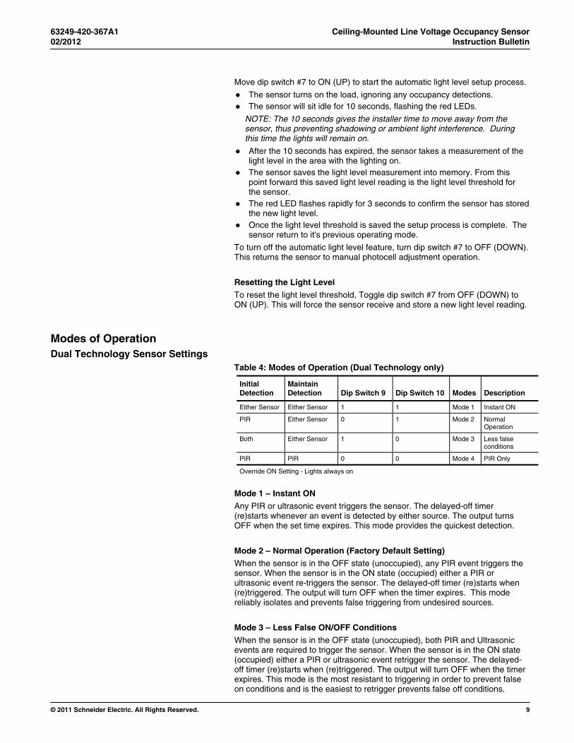
Table 4: Modes of Operation (Dual Technology only)
Initial Detection
Maintain Detection Dip Switch 9 Dip Switch 10 Modes Description
Either Sensor Either Sensor 1 1 Mode 1 Instant ON
PIR Either Sensor 0 1 Mode 2 Normal Operation
Both Either Sensor 1 0 Mode 3 Less false conditions
PIR PIR 0 0 Mode 4 PIR Only
Override ON Setting - Lights always on
Mode 1 – Instant ON Any PIR or ultrasonic event triggers the sensor. The delayed-off timer (re)starts whenever an event is detected by either source. The output turns OFF when the set time expires. This mode provides the quickest detection.
Mode 2 – Normal Operation (Factory Default Setting) When the sensor is in the OFF state (unoccupied), any PIR event triggers the sensor. When the sensor is in the ON state (occupied) either a PIR or ultrasonic event re-triggers the sensor. The delayed-off timer (re)starts when (re)triggered. The output will turn OFF when the timer expires. This mode reliably isolates and prevents false triggering from undesired sources.
Mode 3 – Less False ON/OFF Conditions
When the sensor is in the OFF state (unoccupied), both PIR and Ultrasonic events are required to trigger the sensor. When the sensor is in the ON state (occupied) either a PIR or ultrasonic event retrigger the sensor. The delayed-off timer (re)starts when (re)triggered. The output will turn OFF when the timer expires. This mode is the most resistant to triggering in order to prevent false on conditions and is the easiest to retrigger prevents false off conditions.
Ceiling-Mounted Line Voltage Occupancy Sensor 63249-420-367A1 Instruction Bulletin 02/2012
10 © 2011 Schneider Electric. All Rights Reserved.
Mode 4 - PIR Only
In this mode, a PIR event is required to trigger the sensor, the Ultrasonic is disabled. The delayed-off timer (re)starts whenever an event is detected by the PIR. The output turns OFF when the timer expires. When operating in this mode, the unit detects PIR only. This mode is typically used when a sensor is installed close to an air diffuser or return grill.
Walk-Through Mode The sensor's walk-through mode is enabled or disabled using of dip switch # 4. To enable Walk-through mode, push dip switch #4 to ON (UP). To disable Walk-through mode, push dip switch #4 to OFF (DOWN).
When the walk-through mode is enabled and the sensor is initially OFF, the sensor initiates a temporary two minute time-out value when movement is first detected. This feature can be used with any dip switch time out value greater then 2 minutes.
If no movement is detected after the first 30 seconds, the sensor will time-out after 2 minutes.
If movement is detected after the first 30 seconds, the sensor reverts to the normal time-out value.
Adaptive PIR The Adaptive PIR feature is enabled or disabled using dip switch # 5.
When the Adaptive PIR feature is enabled the PIR sensor initially detects motion based on the setting of the sensitivity dial.
After initial occupancy detection and the load has turned on, the PIR sensor’s sensitivity automatically moves to 100% (max.) sensitivity. The sensor remains at 100% (max.) sensitivity until the sensor's timer expires. Once the timer expires and the load turns off, the PIR sensitivity returns to the original dial setting.
When the Adaptive PIR feature is disabled the sensor only uses the sensitivity dial.
Adaptive Timing The adaptive timing feature is enabled or disabled using of dip switch #6. The feature uses dip switches 1-3 as time-out setting for the starting/minimum time-out value.
The variable time-out period is based on the time-out event, not the sensing of multiple movements, or measuring the time between movements. If movement is detected when the sensor is near time-out, or immediately after time-out, then the time-out is increased.
The sensor will slowly reduce the time-out if detection does not occur near time-out.
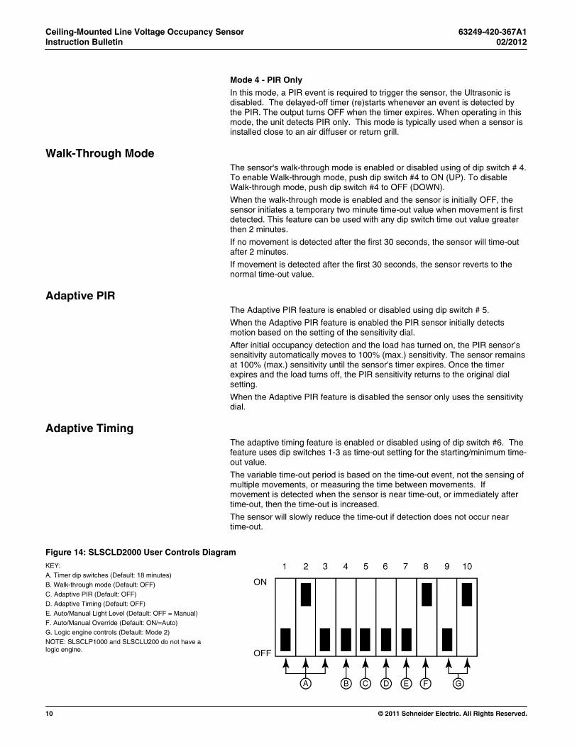
Figure 14: SLSCLD2000 User Controls Diagram
KEY: A. Timer dip switches (Default: 18 minutes) B. Walk-through mode (Default: OFF) C. Adaptive PIR (Default: OFF) D. Adaptive Timing (Default: OFF) E. Auto/Manual Light Level (Default: OFF = Manual) F. Auto/Manual Override (Default: ON/=Auto) G. Logic engine controls (Default: Mode 2) NOTE: SLSCLP1000 and SLSCLU200 do not have a logic engine.
63249-420-367A1 Ceiling-Mounted Line Voltage Occupancy Sensor 02/2012 Instruction Bulletin
© 2011 Schneider Electric. All Rights Reserved. 11
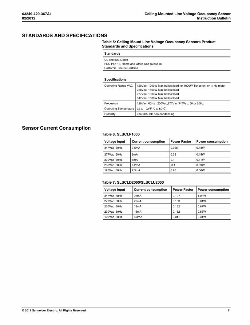
STANDARDS AND SPECIFICATIONS Table 5: Ceiling Mount Line Voltage Occupancy Sensors Product Standards and Specifications
Standards
UL and cUL Listed FCC Part 15, Home and Office Use (Class B) California Title 24 Certified
Specifications
Operating Range VAC 120Vac: 1000W Max ballast load, or 1000W Tungsten, or ¼ Hp motor 230Vac: 1500W Max ballast load 277Vac: 1800W Max ballast load 347Vac: 1500W Max ballast load
Frequency 120Vac: 60Hz ; 230Vac,277Vac,347Vac: 50 or 60Hz
Operating Temperature 32 to 122°F (0 to 50°C)
Humidity 0 to 90% RH non-condensing
Sensor Current Consumption Table 6: SLSCLP1000
Voltage input Current consumption Power Factor Power consumption
347Vac 60Hz 7.5mA 0.068 0.18W
277Vac 60Hz 6mA 0.09 0.15W
230Vac 60Hz 5mA 0.1 0.11W
230Vac 50Hz 4.2mA 0.1 0.09W
120Vac 60Hz 2.5mA 0.20 0.06W
Table 7: SLSCLD2000/SLSCLU2000
Voltage input Current consumption Power Factor Power consumption
347Vac 60Hz 28mA 0.107 1.04W
277Vac 60Hz 22mA 0.133 0.81W
230Vac 60Hz 18mA 0.162 0.67W
230Vac 50Hz 15mA 0.162 0.56W
120Vac 60Hz 8.3mA 0.311 0.31W
Ceiling-Mounted Line Voltage Occupancy Sensor Instruction Bulletin
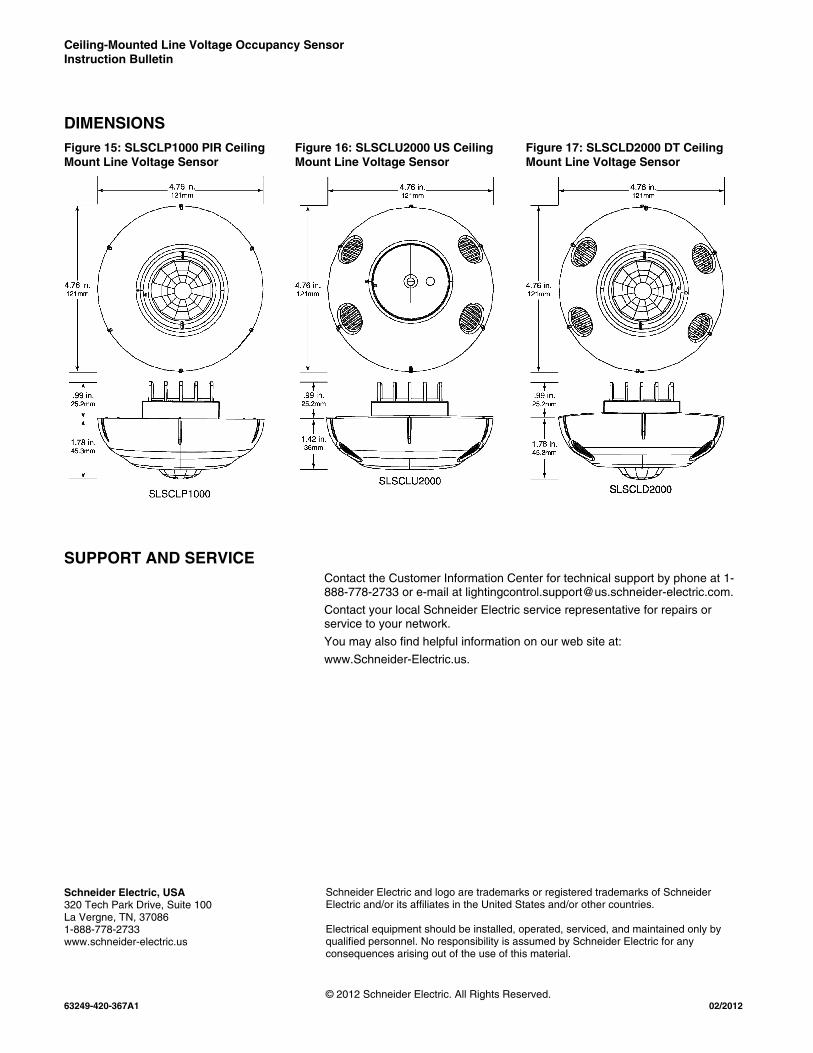
DIMENSIONS Figure 15: SLSCLP1000 PIR Ceiling Mount Line Voltage Sensor
Figure 16: SLSCLU2000 US Ceiling Mount Line Voltage Sensor
Figure 17: SLSCLD2000 DT Ceiling Mount Line Voltage Sensor
SUPPORT AND SERVICE Contact the Customer Information Center for technical support by phone at 1-888-778-2733 or e-mail at [email protected].
Contact your local Schneider Electric service representative for repairs or service to your network.
You may also find helpful information on our web site at:
www.Schneider-Electric.us.
Schneider Electric, USA 320 Tech Park Drive, Suite 100 La Vergne, TN, 37086 1-888-778-2733 www.schneider-electric.us
Schneider Electric and logo are trademarks or registered trademarks of Schneider Electric and/or its affiliates in the United States and/or other countries. Electrical equipment should be installed, operated, serviced, and maintained only by qualified personnel. No responsibility is assumed by Schneider Electric for any consequences arising out of the use of this material.
© 2012 Schneider Electric. All Rights Reserved. 63249-420-367A1 02/2012