Embed Size (px)
Citation preview

CEILOMETERCT25K
User’s Guide
CT25K-U059en-2.126 February 1999
Vaisala 1999

© Vaisala 1999
No part of this manual may be reproduced in any form or by any means,electronic or mechanical (including photocopying), nor may its contents becommunicated to a third party without prior written permission of thecopyright holder.
The contents of instruction manuals are subject to change without priornotice.

Ceilometer CT25KCT25K-U059en-2.1 User’s Guide
i
Contents
LIST OF FIGURES............................................................................................................ IV
INTRODUCTION TO MANUAL ........................................................................................ VII
VALIDITY OF THIS MANUAL ......................................................................................... VIII
SAFETY SUMMARY ......................................................................................................... IX
1. GENERAL INFORMATION....................................................................................... 1
1.1 Product Overview .......................................................................................... 1
1.2 Specifications ................................................................................................ 31.2.1 Mechanical ................................................................................... 31.2.2 External Connector J1 - Window conditioner ................................ 31.2.3 External Connector J2 - Power input ............................................ 31.2.4 Output Interface ........................................................................... 41.2.4.1 External Connector J3 - Data line ................................................. 41.2.4.2 External Connector J4 - Maintenance line .................................... 61.2.5 Modem Options ............................................................................ 61.2.5.1 Modem board DMX55................................................................... 61.2.5.2 Modem board DMX50................................................................... 71.2.5.3 ANet Interface DMX611 ............................................................. 71.2.6 Transmitter ................................................................................... 81.2.7 Receiver ....................................................................................... 81.2.8 Optical System ............................................................................. 91.2.9 Performance................................................................................. 91.2.10 Environmental Conditions............................................................. 9
2. INSTALLATION...................................................................................................... 10
2.1 Unloading and unpacking ........................................................................... 10
2.2 Foundation................................................................................................... 11
2.3 Assembling the Unit .................................................................................... 12
2.4 Using the Tilt Feature.................................................................................. 14
2.5 Cable Connections ...................................................................................... 15
2.6 Grounding.................................................................................................... 16
2.7 Connection of Maintenance Terminal ........................................................ 17
3. START UP.............................................................................................................. 19
3.1 Start up procedure ...................................................................................... 193.1.1 Mobile operation aspects............................................................ 21
3.2 Verification of Proper Operation ................................................................ 21
3.3 Settings for Normal Operation.................................................................... 22
3.4 Factory settings of user programmable parameters ................................. 22
4. OPERATION........................................................................................................... 25
4.1 Operation Modes ......................................................................................... 25
4.2 Serial Lines. Open and Closed Port ........................................................... 25
4.3 User Commands .......................................................................................... 27
4.4 Data Messages ............................................................................................ 33

Ceilometer CT25KUser’s Guide CT25K-U059en-2.1
ii
4.4.1 Data Message No. 1 ................................................................... 334.4.2 Data Message No. 2 ................................................................... 364.4.3 Data Message No. 3 ................................................................... 384.4.4 Data Message No. 4 ................................................................... 394.4.5 Data Message No. 5 ................................................................... 394.4.6 Data Message No. 6 ................................................................... 394.4.7 Data Message No. 7 ................................................................... 404.4.8 (Spare) ....................................................................................... 414.4.9 (Spare) ....................................................................................... 414.4.10 DMX611 operation (option) ......................................................... 414.4.11 Status Message "S" .................................................................... 424.4.12 Manual Message......................................................................... 45
4.5 Polling mode ................................................................................................ 45
4.6 Prevailing parameter settings ..................................................................... 46
4.7 Manual angle setting ................................................................................... 47
5. FUNCTIONAL DESCRIPTION ................................................................................ 49
5.1 Theory of Operation..................................................................................... 49
5.2 Technical Description.................................................................................. 535.2.1 General....................................................................................... 535.2.2 LIDAR Measurement................................................................... 555.2.3 Internal Monitoring and Control ................................................... 58
5.3 Module Descriptions.................................................................................... 585.3.1 Optical Subassembly CTB22....................................................... 585.3.2 Laser Transmitter CTT21 ............................................................ 595.3.3 Receiver CTR21 ......................................................................... 605.3.4 Optics Monitor CTL21 ................................................................. 615.3.5 Board Frame DMF51 .................................................................. 625.3.6 Processor Board DMC50B .......................................................... 635.3.7 DC Converter DPS52.................................................................. 675.3.8 Ceilometer Interface Board DCT51 ............................................. 695.3.9 Line and Power Interface Subassembly CTP241 ........................ 705.3.10 Internal Heaters Subassembly CT25039 ..................................... 725.3.11 Tilt Angle Sensor CT3675 ........................................................... 735.3.12 Window Conditioner CT2614 / CT2688 ....................................... 745.3.13 Maintenance Terminal PSION3 (Option) ..................................... 755.3.14 Modem DMX55 (Option) ............................................................. 765.3.15 Modem DMX50 (Option) ............................................................. 785.3.16 DMX611 ANet Interface (Option) .............................................. 80
5.4 Sky Condition Algorithm ............................................................................. 835.4.1 General....................................................................................... 835.4.2 Option code ................................................................................ 835.4.3 Activation .................................................................................... 835.4.4 Algorithm overview...................................................................... 84
6. PERIODIC MAINTENANCE .................................................................................... 87
6.1 Alarms and warnings................................................................................... 87
6.2 Window Cleaning ......................................................................................... 87
6.3 Battery check ............................................................................................... 88
6.4 Storage ......................................................................................................... 88
7. TROUBLESHOOTING ............................................................................................ 89
7.1 Normal Operation......................................................................................... 897.1.1 Equipment .................................................................................. 89

Ceilometer CT25KCT25K-U059en-2.1 User’s Guide
iii
7.1.2 Instructions................................................................................. 89
7.2 Troubleshooting .......................................................................................... 937.2.1 Warnings .................................................................................... 937.2.2 Alarms........................................................................................ 967.2.3 Miscellaneous............................................................................. 97
7.3 Failure Diagnosis ........................................................................................ 98
8. REPAIR .................................................................................................................. 99
8.1 General......................................................................................................... 99
8.2 Writing conventions used ........................................................................... 99
8.3 Start-up procedure for replacement (all parts) .........................................100
8.4 Transmitter CTT21......................................................................................1018.4.1 Removal ....................................................................................1018.4.2 Replacement .............................................................................1028.4.3 Compensation adjustments .......................................................105
8.5 Receiver CTR21 ..........................................................................................1088.5.1 Removal ....................................................................................1088.5.2 Replacement .............................................................................1098.5.3 Coaxial Cable Replacement ......................................................1118.5.3.1 Removal ....................................................................................1118.5.3.2 Replacement .............................................................................112
8.6 Compensation Fiber ...................................................................................1138.6.1 Compensation Fiber replacement ..............................................113
8.7 Optics Monitor CTL21 ................................................................................1148.7.1 Removal ....................................................................................1148.7.2 Replacement .............................................................................115
8.8 Boards of Board Frame DMF51 .................................................................1168.8.1 Removing boards ......................................................................1168.8.2 Replacing boards ......................................................................1178.8.2.1 Parameter settings of Ceilometer Interface board DCT51..........117
8.9 Line & Power Subassembly CTP241 .........................................................1178.9.1 Removal ....................................................................................1178.9.2 Replacement .............................................................................1198.9.3 Internal Heater Subassembly CT25039 Replacement................1208.9.4 Battery 4592 replacement instructions.......................................121
INDEX .............................................................................................................................123

Ceilometer CT25KUser’s Guide CT25K-U059en-2.1
iv
LIST OF FIGURES
Figure 1-1 Ceilometer CT25K ..........................................................................................1
Figure 1-2 Data Line Connection Options.........................................................................5
Figure 2-1 Measurement Unit Handle .............................................................................10
Figure 2-2 Foundation Construction ...............................................................................11
Figure 2-3 Mounting the Pedestal ...................................................................................12
Figure 2-4 Attaching the Measurement Unit and the Shield............................................13
Figure 2-5 External Connectors (bottom view) ...............................................................15
Figure 2-6 Termination Box Wire Connections ..............................................................16
Figure 3-1 CT25K Switches and LEDs ...........................................................................20
Figure 4-1 Operation Modes ...........................................................................................25
Figure 4-2 Open and closed port .....................................................................................26
Figure 5-1 Typical Measurement Signal .........................................................................49
Figure 5-2 Measurement Unit Components.....................................................................53
Figure 5-3 Subassembly Interconnections.......................................................................54
Figure 5-4 Block Diagram of Operational Units .............................................................56
Figure 5-5 Optical Subassembly CTB22 with Optics Monitor, Transmitter and ReceiverSubassemblies ...............................................................................................58
Figure 5-6 CTT21 Block Diagram ..................................................................................59
Figure 5-7 CTR21 Block Diagram ..................................................................................60
Figure 5-8 CTL21 Block Diagram ..................................................................................61
Figure 5-9 DMF51 Frame ...............................................................................................62
Figure 5-10 DMC50B Block Diagram ............................................................................63
Figure 5-11 DIP Switch Settings of the DMC50 .............................................................66
Figure 5-12 DPS52 Block Diagram.................................................................................67
Figure 5-13 DCT51 Block Diagram................................................................................69
Figure 5-14 CTP241 Wiring ...........................................................................................71

Ceilometer CT25KCT25K-U059en-2.1 User’s Guide
v
Figure 5-15 CT25039 Wiring Diagram .......................................................................... 72
Figure 5-16 CT3675 Tilt Angle Sensor .......................................................................... 73
Figure 5-17 Window Conditioner CT2614/CT2688 ....................................................... 74
Figure 5-18 RS Cable..................................................................................................... 75
Figure 5-19 DMX55 Block Diagram.............................................................................. 76
Figure 5-20 DMX50 Block Diagram.............................................................................. 78
Figure 5-21 DMX611 Block Diagram ............................................................................ 80
Figure 8-1 Board Connectors of the DMF51 Board Frame............................................101
Figure 8-2 Removing the Laser Transmitter..................................................................102
Figure 8-3 Adjusting the compensation.........................................................................106
Figure 8-4 Adjusting the compensation.........................................................................107
Figure 8-5 Removing the Receiver................................................................................109
Figure 8-6 Removing the Optics Monitor......................................................................115
Figure 8-7 Boards of the DMF51 Board Frame .............................................................116
Figure 8-8 Removing Line and Power Interface Subassembly CTP241.........................119
Figure 8-9 Internal heater replacement..........................................................................121
Figure 8-10 Battery replacement ...................................................................................122

Ceilometer CT25KUser’s Guide CT25K-U059en-2.1
vi
This page intentionally left blank.

Ceilometer CT25KCT25K-U059en-2.1 User’s Guide
vii
INTRODUCTION TO MANUAL
The purpose of this User’s Guide is to be a general information source as wellas a detailed operational guide for the user of Ceilometer CT25K.
This document is divided into 8 chapters. Chapter 1 offers an overview andtechnical specifications of the CT25K Ceilometer. The following chapters 2and 3 contain installation and start up instructions. Operational instructionswith user commands and data messages are included in chapter 4. Chapter 5includes functional description of the Ceilometer and chapters 6, 7 and 8instructions for maintenance, troubleshooting and repair.

Ceilometer CT25KUser’s Guide CT25K-U059en-2.1
viii
VALIDITY OF THIS MANUAL
This manual covers ceilometer CT25K in all its configurations as defined bythe parts and options listed in section 1.1, running under software revision
CT25K- 2.01 or 2.01a
Table 1-1 lists the revision history that may apply in comparison to other unitsin use:
Software revisions DescriptionCT25K-1.01 First ReleaseCT25K-1.02 Intermediate release (not in use)CT25K-1.03 Intermediate release (not in use)CT25K-1.04 Production rev. 95-05-15...97-02-03CT25K-1.04h Special rev. with Qualimetrics and
DR21 messagesCT25K-1.05 Production rev. 97-02-03...CT25K-2.00 Production rev. 97-11-01...CT25K-2.01 Production rev. 98-03-17...CT25K-2.01a Production rev. 99-02-09…
Table 1-1 Software Revisions
Table 1-2 lists the hardware history that may apply in comparison to otherunits in use:
Hardware history DescriptionCT25K model A First ReleaseCT25K model B Enclosure CT1669 replaced with CT15035.
Model A pedestal CT2665 (Fiberglass) is optionNew Metal Pedestal CT25106 is standard.Line and Power Interface Subassembly CTP21changed to CTP241.Internal Heaters Subassembly CT2690 replacedwith CT25039.
CTB22 Replaces CTB21 since 97-05-26DMC50B Replaces DMC50A since 97-11-05DPS52 Replaces DPS51
Table 1-2 Hardware History

Ceilometer CT25KCT25K-U059en-2.1 User’s Guide
ix
SAFETY SUMMARY
The following safety precautions must be observed during all phases ofoperation, service, and repair of this instrument. Failure to comply with theseprecautions or with specific warnings elsewhere in this manual violates safetystandards of design, manufacture, and intended use of the instrument.VAISALA assumes no liability for the customer’s failure to comply with theserequirements.
LASER SAFETY
The CT25K is officially certified as a Class 1 laser device in accordance withEuropean standard EN 60 825-1:1994. It is also classified in accordance withU.S. regulation 21 CFR 1040 as a Class 1 laser device. This means that aCT25K Ceilometer installed in a field environment with instrument covers onand pointed vertically or near-vertically poses no established biologicalhazard to humans.
The device is equipped with the following label:
The instrument is intended for operation in an area restricted from publicaccess, and to be pointed vertically or near-vertically up. The followingprecautions are to be noted and followed during service and maintenance ofthe instrument:
• Never look directly into the Laser Transmitter with magnifying optics(glasses, binoculars, telescopes, etc.)
• When operating, avoid looking at the ceilometer unit from the beamdirection. When tilting the unit, make sure that it is not being viewed fromthe beam direction with magnifying optics.
• Only trained personnel should perform maintenance functions. Work areaaccess by unauthorized persons during service operations must beprevented.

Ceilometer CT25KUser’s Guide CT25K-U059en-2.1
x
GROUND THE INSTRUMENT
To minimize shock hazard, the instrument chassis and cabinet must beconnected to an electrical ground. The instrument is equipped with athree-conductor AC power connector. The power cable must either beplugged into an approved three-contact electrical outlet or the instrument mustbe carefully earthed to a low-resistance safety ground.
DO NOT OPERATE IN AN EXPLOSIVE ATMOSPHERE
Do not operate the instrument in the presence of flammable gases or fumes.Operation of any electrical instrument in such an environment constitutes adefinite safety hazard.
DO NOT SERVICE OR ADJUST ALONE
Do not attempt internal service or adjustment unless another person, capableof rendering first aid and resuscitation, is present.
DO NOT SUBSTITUTE PARTS OR MODIFY INSTRUMENT
Because of the danger of introducing additional hazards, do not installsubstitute parts or perform any unauthorized modification to the instrument.Return the instrument to a VAISALA office or authorized Depot for serviceand repair to ensure that safety features are maintained.
KEEP AWAY FROM LIVE CIRCUITS
Operating personnel must not remove instrument covers. Componentreplacement and internal adjustments must be made by qualified maintenancepersonnel. Do not replace components with power cable connected. Undercertain conditions, dangerous voltages may exist even with the power cableremoved. To avoid injuries, always disconnect power and discharge circuitsbefore touching them.
High voltage will be readily accessible when the transmitter (CTT21) orreceiver (CTR21) covers are removed and they are connected to a poweredunit. High voltage is present in the Line and Power Interface Subassembly(CTP241), the Internal Heaters subassembly, the Frame (DMF51) MotherBoard, and the Window Conditioners at the top of the Shield.
Transmitter (CTT21), Receiver (CTR21), and Line and Power InputSubassembly (CTP241) have the following warning label:
WARNING! +,*+92/7$*(,16,'(7+,6(1&/2685(

Ceilometer CT25KCT25K-U059en-2.1 User’s Guide
xi
Internal Heaters Subassembly can be hot and has the following warninglabels:
DANGEROUS PROCEDURE WARNINGS
Warnings, such as the example below, precede potentially dangerousprocedures throughout this manual. Instructions contained in the warningsmust be followed:
WARNING
Dangerous voltages, capable of causing death, are presentin this instrument. Use extreme caution when handling,testing, and adjusting.
CAUTION
The equipment contains parts and assemblies sensitive todamage by Electrostatic Discharge (ESD). Use ESDprecautionary procedures when touching, removing orinserting.

Ceilometer CT25KUser’s Guide CT25K-U059en-2.1
xii
This page intentionally left blank.

Ceilometer CT25KCT25K-U059en-2.1 User’s Guide
1
1. GENERAL INFORMATION
1.1 Product Overview
Ceilometer CT25K measures cloud heights and vertical visibilities. The smalland lightweight measurement unit suits well for mobile operation.
The CT25K Ceilometer employs pulsed diode laser LIDAR technology(LIDAR = Light detection and ranging), where short, powerful laser pulsesare sent out in a vertical or near-vertical direction. The reflection of light -backscatter - caused by haze, fog, mist, virga, precipitation and clouds ismeasured as the laser pulses traverse the sky. The resulting backscatterprofile, i.e. signal strength versus height, is stored and processed and thecloud bases are detected. Knowing the speed of light, the time delay betweenthe launch of the laser pulse and the detection of the backscatter signalindicates the cloud base height.
The CT25K is able to detect three cloud layers simultaneously. Besides cloudlayers it detects whether there is precipitation or other obstructions to vision.No adjustments in the field are needed. The embedded software includesseveral service and maintenance functions and gives continuous statusinformation from internal monitoring. The software is designed to give thefull backscatter profile.
MEASUREMENT UNIT
SHIELD
PEDESTAL
9 4 12 -0 2 6
Figure 1-1 Ceilometer CT25K
Ceilometer CT25KUser’s Guide CT25K-U059en-2.1
2
Ceilometer CT25K consists of three main parts (Figure 1-1):
1. Measurement Unit including
- Optical Subassembly CTB22
- Laser transmitter CTT21
- Receiver CTR21
- Optics Monitor CTL21
- Frame DMF51 including
- Processor Board DMC50B- DC Converter DPS52- Ceilometer Interface Board DCT51- Modem (optional)
- Line and Power Interface Subassembly CTP241
- No-Break Battery
- Internal Heaters Subassembly CT25039
- Tilt Angle Sensor CT3675
- Internal Cables etc.
2. Shield including
- Built-in Window Conditioner CT2614/CT2688 (warm air blower)
options - 220...240 VAC (CT2614)- 100...115 VAC (CT2688)
3. Pedestal
- Metal pedestal CT25106 is standard. For off-shore applications it isrecommended to use fiberglass pedestal CT2665.
The complete delivery also includes mating cables with connectors for powerand communication, installation hardware, an Allen key, a triangle key for theMeasurement Unit door and this CT25K User’s Guide.
In addition, the following options may be included in the delivery:
- Maintenance Terminal (Palmtop computer) PSION3 - connected to Measurement Unit at the external connector J4 via RS-
232 interface
- Termination Boxes (2) for Line Power CT3709 (external connector J2)and Communication Cable CT3707 (external connector J3) connections
- Tropics Window CT35043 on Measurement Unit instead of StandardWindow to protect the laser from direct sun radiation.
- Optical Termination Hood CT25184 for indoor service use

Ceilometer CT25KCT25K-U059en-2.1 User’s Guide
3
- Shock Absorber CT35022 for ship installations
- PC Terminal cable CT35198 to connect the connector of the RS-232 portof the PC to the maintenance port
1.2 Specifications
1.2.1 Mechanical
Dimensions:
Measurement unit 760 x 280 x 245 mm(30 x 11 x 10 in.)
Height with shield and pedestal 1320 mm (52 in.)
Weight:
Measurement unit 17 kg (37 lb.)Shield 10 kg (22 lb.)Metal pedestal 8 kg (17 lb.)Fiberglass pedestal (option) 13 kg (28 lb.)
Cardboard transport container size 1170 x 740 x 430 mm (46 x 29 x 17 in.)Cardboard transport container weight 51 kg (111 lb.)
Plywood transport container size 1240 x 760 x 450 mm (49 x 30 x 18 in.)Plywood transport container weight 70 kg (152 lb.)
1.2.2 External Connector J1 - Window conditioner
Connector J1: Type Binder series 693, 09-4228-00-07(female)
Mating connector type: Type Binder series 693, 99-4225-70-077-pin (male) elbow
1.2.3 External Connector J2 - Power input
At nominal line voltage 115 V or 230 V
Power consumption (typical) Total 365 W Measurement unit 15 W Internal heater 120 W Window conditioner heater 200 W Window blower 30 W
Frequency 45-65 Hz

Ceilometer CT25KUser’s Guide CT25K-U059en-2.1
4
Power connector (J2): Type Binder series 693, 09-4223-00-044-pin (male)
Mating connector type: Type Binder series 693, 99-4222-70-04(female) elbow
No-break power supply 12V Sealed Lead Acid Battery, 2 Ah
Overvoltage Protection Low-press filter , VDR
1.2.4 Output Interface
The data port can operate according to the following serial line standards :
RS-232
RS-422
RS-485, multidrop, 2-wire / 4-wire
The data port can also be operated through DMX55 and DMX50 modems orANet Bus interface DMX611.
The maintenance port is an RS-232 serial line, except when the data line is setto RS-422 or RS-485; then the maintenance line voltage levels become 0 and+5 V.
1.2.4.1 External Connector J3 - Data line
The data line is intended to be used for measurement data communication, butit can also be used with Ceilometer Maintenance Terminal, PC or otherterminals.
Connector (J3): Type Binder series 693, 09-4227-00-077-pin (male)
Mating connector type: Type Binder series 693, 99-4226-70-07(female) elbow
Baud Rate: 2400 baud standard with RS-232300, 4800 and 9600 baud available300 bit/s with modem DMX552400 bit/s standard with modem DMX50300, 1200, 2400 bit/s availableData compression allows up to 9600 bit/sthroughput
Max. Distance to Operate: 300m (1000 ft) with RS-232,1.2 km (4000 ft) with RS-422 and RS-485,all at 2400 baud with typical communicationcables16 km (10 mi) with Modem

Ceilometer CT25KCT25K-U059en-2.1 User’s Guide
5
Standard Character Frame: 1 Start Bit7 Data BitsEven Parity1 Stop Bit
Standard Character Code: USASCII
Pin Connections 1 RD- / AN2Lo2 Modem Lead A / RxD / RD+ / AN1Hi3 Modem Lead B / TxD / SD+ / AN1Lo4 Signal Ground5 SD- / AN2Hi6 +12 V DC supply (200 mA max for 1
hour, 100 mA continuous, for externalequipment)
Modem circuits are non-polar and symmetrical. All modem circuits areelectrically floating to overvoltage protection rating (300V-500V).
Overvoltage Protection in each circuit:Primary Noble Gas Surge ArresterSecondary VDRs, Transient Zener Diodes
or normal Diodes
Figure 1-2 Data Line Connection Options

Ceilometer CT25KUser’s Guide CT25K-U059en-2.1
6
1.2.4.2 External Connector J4 - Maintenance line
Maintenance line is intended for on-site maintenance and can be used withCeilometer Maintenance Terminal, PC or other terminal.
Connector (J3): Type Binder series 693, 09-4224-06-044-pin (male)
Mating connector type: Type Binder series 693, 99-4221-70-04(female) elbow
Baud Rate: 2400 baud standard and default300, 4800, 9600 baud available
Distance to Operate: 300 m (1000 ft) at 2400 baud with typicalcommunication cables
Standard Character Frame: 1 Start Bit7 Data BitsEven Parity1 Stop Bit
Standard Character Code: USASCII
Pin Connections 1 RxD / RD+ (0...5 V)2 TxD / SD+ (0...5 V)3 +12 V DC supply from internal battery
(100 mA continuous, 200 mA max.)4 Signal Ground / Equipment Ground
Overvoltage Protection in each circuit:Primary Noble Gas Surge ArresterSecondary VDRs, Transient Zener Diodes or
normal Diodes
1.2.5 Modem Options
1.2.5.1 Modem board DMX55
ITU-T V.21 / Bell 103 full duplex modem interface for serial asynchronousdata interchange
Data Rate: 300 bit/s
Modulation method: FSK

Ceilometer CT25KCT25K-U059en-2.1 User’s Guide
7
Answer Mode Standard Frequencies:V.21 Bell 103
Mark (1) 1650 Hz 2225 HzSpace (0) 1850 Hz 2025 Hz
Originate Mode Optional
Signal Level: -10 dBm (0.3 V) into 600 Ohm standard(Jumper selectable)
Max. Distance to Operate 0...16 km (0...10 miles)
with 22 AWG (0.35 mm2) unshieldedtwisted pair
The signal circuit is electrically floating to overvoltage protection rating(300V-500V).
1.2.5.2 Modem board DMX50
Processor: Intel 80C32 custom version
Modem: Signal Processor Chip Silicon Systems SSI73K224L
Modem standards supported: V.21/ V.22/ V.22bis and Bell 103, Bell 212
Modulation method: 300 FSK/ 1200 DPSK/ 2400 QAM
Compression & error correction: V. 42, V.42bis and MNP 2-5
Adaptive equalization for optimum performance over all lines.
1.2.5.3 ANet Interface DMX611
The DMX611 serves as an interface between the CT25K and Vaisalaproprietary ANet and INet busses.
Baud Rate 2400
Signal Level 0 dBm
Max. Distance to Operate 0…5 km multi-drop networkTwisted pair 22 AWG
Standard Character Frame 8 Bit synchronous
Character Code Binary
iNet protocol Packet format.

Ceilometer CT25KUser’s Guide CT25K-U059en-2.1
8
1.2.6 Transmitter
Laser Source: Indium Gallium Arsenide (InGaAs) DiodeLaser
Center Wavelength: 905 ± 5 nm at 25 °C (77 °F)
Operating Mode: Pulsed
Nominal Pulse Properties at Full Range Measurement:Energy: 1.6 µWs ± 20% (factory adjustment)Peak Power: 16 W typicalWidth, 50%: 100 ns typical
Repetition Rate: 5.57 kHz
Average Power: 8.9 mW (full range measurement)
Max Irradiance: 170 µW/cm² measured with 7 mm aperture
Laser Classification: Officially certified as Class 1 laser device inaccordance with EN 60 825-1:1994Class 1 in compliance with FDA CFR1040.10 (Subsection e,3)
Laser Source Geometry: Five-stack, 0.4 mm (16 mil) square
Beam Divergence: ± 0.53 mrad edge, ± 0.75 mrad diagonal
1.2.7 Receiver
Detector: Silicon Avalanche Photodiode (APD)Responsivity at 905 nm: 65 A/W(factory adjustment)
Surface Diameter: 0.5 mm (0.02 in.)
Interference Filter: Center wavelength 908 nm typical
50% Pass Band: 35 nm at 890-925 nm typical
Transmissivity at 905 nm: 80 % typical, 70 % minimum
Field-of-View Divergence: ± 0.66 mrad
Ceilometer CT25KCT25K-U059en-2.1 User’s Guide
9
1.2.8 Optical System
Optics System Focal Length: 377 mm (14.8 in.)
Effective Lens Diameter: 145 mm (5.7 in.)
Lens Transmittance: 96 % typical
Window Transmittance: 98 % typical, clean
1.2.9 Performance
Measurement Range: 0...25,000 ft. (0...7.5 km)
Resolution: 50 ft
25,000 ft. Acquisition Time: min. 15 smax. 120 s
Receiver Bandwidth: 3 MHz (-3db)
1.2.10 Environmental Conditions
Ambient Temperature: -50...+60 °C (-60 ...+140 °F)
Humidity: to 100 %RH
Wind: to 100 kt (50 m/s)
Vibration: 0.5 g 5 - 500 Hz

Ceilometer CT25KUser’s Guide CT25K-U059en-2.1
10
2. INSTALLATION
NOTE
Before the installation, make sure that the CT25Kconfiguration, especially line voltage setting, is incompliance with local circumstances. Information aboutthe CT25K configuration in question is included in thedelivery.
2.1 Unloading and unpacking
The CT25K is shipped in one container containing the Measurement Unit,Shield and Pedestal, and all equipment, accessories and documentation neededfor carrying out the installation. Store the original packaging for possible latertransport need.
For opening, the package is to be placed on a flat surface with the indicatedtop side up. The container is opened from the top side and the ceilometerincluding all other parts are carefully removed.
• Use proper gloves for protection against sharp edges, etc.
• Avoid touching the window or lens surfaces unless cleaning according toinstructions.
• Maintain the integral protective caps on the unused external connectors (J3Data line or J4 Maintenance line).
• Use the measurement unit handle for lifting and carrying (Figure 2-1).
Figure 2-1 Measurement Unit Handle
If mishandling occurs during transit or installation, the instrument should bereturned to a VAISALA office or authorized Depot for inspection.
Ceilometer CT25KCT25K-U059en-2.1 User’s Guide
11
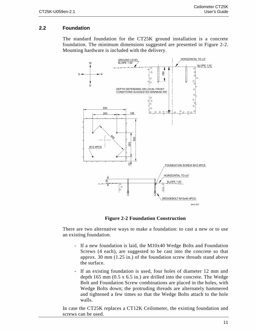
2.2 Foundation
The standard foundation for the CT25K ground installation is a concretefoundation. The minimum dimensions suggested are presented in Figure 2-2.Mounting hardware is included with the delivery.
Figure 2-2 Foundation Construction
There are two alternative ways to make a foundation: to cast a new or to usean existing foundation.
- If a new foundation is laid, the M10x40 Wedge Bolts and FoundationScrews (4 each), are suggested to be cast into the concrete so thatapprox. 30 mm (1.25 in.) of the foundation screw threads stand abovethe surface.
- If an existing foundation is used, four holes of diameter 12 mm anddepth 165 mm (0.5 x 6.5 in.) are drilled into the concrete. The WedgeBolt and Foundation Screw combinations are placed in the holes, withWedge Bolts down; the protruding threads are alternately hammeredand tightened a few times so that the Wedge Bolts attach to the holewalls.
In case the CT25K replaces a CT12K Ceilometer, the existing foundation andscrews can be used.

Ceilometer CT25KUser’s Guide CT25K-U059en-2.1
12
If the tilt feature will be used (see section 2.4), observe this in the layout ofthe foundation screws and pedestal placement.
2.3 Assembling the Unit
The CT25K Ceilometer is assembled in four stages:
1. Mount the pedestal on the foundation.
2. Attach the measurement unit to the pedestal.
3. Mount the shield on the measurement unit.
4. Connect the external cables.
1. Place the Pedestal on the foundation (or equivalent installation place) sothat the vertical leg of the pedestal faces East in the Northern hemisphere,and West in the Southern hemisphere.
Figure 2-3 Mounting the Pedestal
If the tilt feature will be used (see section 2.4.), observe this in the layout ofthe foundation screws and pedestal placement. Place the flat washers on thefoundation screws and fix the nuts (Figure 2-3).
2. Start mounting the measurement unit by rotating the friction ring of theflange to the position shown in Figure 2-4 (the screw holes horizontally).Remove the Allen head screws (2 pcs) and flat washers.

Ceilometer CT25KCT25K-U059en-2.1 User’s Guide
13
Place the measurement unit on the pedestal flange. Attach the pedestal flangeto the measurement unit by the two Allen head screws with flat washers. AnAllen key is included in the delivery.
Figure 2-4 Attaching the Measurement Unit and the Shield
3. Before placing the shield pull the knobs (pidgeon blue) on the shieldoutwards. Place the shield carefully on the Measurement Unit; be carefulwith the Window Conditioner cable. Tighten the two attachment knobs(Figure 2-4).
Before connecting the Window Conditioner cable check that the voltagerating of the Window Conditioner (written at its connector) is correct.Connect the Window Conditioner cable plug of the shield to themeasurement unit external connector J1.
Connect external cables according to section 2.5.

Ceilometer CT25KUser’s Guide CT25K-U059en-2.1
14
2.4 Using the Tilt Feature
The Measurement Unit and Pedestal of Ceilometer CT25K are designed sothat the unit can operate in a tilted direction. The built-in tilt angle sensorCT3675 detects the tilt angle, i.e. deviation from the vertical. The tilt angleranges from -15 to +90 degrees from vertical; the angle is positive when themeasurement unit door turns towards the ground. The cosine of the tilt angleis used for automatic correction of the detected cloud base height, whichenables accurate cloud base measurements also in a tilted direction.
Several advantages can be realized with the aid of this feature:
• Heavy weather conditions
Using a slight tilt angle for instance 15 degrees, the measurement unitwindow is kept better protected from precipitation, thus enhancing theavailability of correct measurements in heavy weather conditions.
• Aircraft approaches
The beam can be directed towards a direction, which better represents theapproach of an aircraft than the straight vertical. Useful e.g. for helicopterapproaches, and sites where the ceilometer cannot be located exactly at thedesired spot.
• Hard target and testing purposes
Tilting the unit down by 90 degrees permits verification of operationagainst a hard target at a known distance. Useful in connection withinstallation and maintenance. Enables real backscatter signal detectionwhen there are no clouds in the sky.
WARNING
Make sure that nobody is viewing the unit from the beamdirection with magnifying optics!
• Maintenance
By tilting the unit back -15 degrees, better access is gained to the interiorduring maintenance.
• In the tropics
Between the latitudes of ± 25 degrees, where the sun can be straight abovethe unit, a slight tilting prevents the laser from direct sun radiation, whichwould otherwise destroy the laser. The other alternative is to use a tropicswindow on the measurement unit instead of a standard window.

Ceilometer CT25KCT25K-U059en-2.1 User’s Guide
15
As these advantages are partly contradictory and cannot or need not all berealized, the user must decide the final installation direction. In doing so, thefollowing must be observed:
NOTE
Unless a tropics window is used, the unit must never bedirected so that the sun shines directly into the optics,because the lens will focus all radiation into a very hotspot.
2.5 Cable Connections
All external connectors to the Measurement Unit are located at the bottom leftedge as seen from the door direction. Figure 2-5 shows the externalconnectors J1, J2, J3 and J4.
Figure 2-5 External Connectors (bottom view)
• The Window Conditioner (warm air blower) mounted in the Shield ispermanently connected to J1.
• Line Power input is connected to J2.

Ceilometer CT25KUser’s Guide CT25K-U059en-2.1
16
• Remote communication is normally connected to J3.
• A local maintenance terminal, for example PSION3, is intended to beconnected to J4. A protective cap is included for covering J4 when not inuse.
External mating connectors with 2 m (7 ft.) cable are included for J2 and forJ3. The power plug of the J2 cable can be cut when the unit is permanentlyinstalled at the final site.
The cables for J2 and J3 are intended to be drawn through the hole of thepedestal to the connectors. Provide sufficient slack for permitting the unit tobe tilted later.
Figure 2-6 shows the connecting signal leads with optional Power and SignalTermination Boxes.
Figure 2-6 Termination Box Wire Connections
Suggested wire dimensions for the external cabling are:
Line Power Supply: 3 x 1.5 mm2 (AWG 16)
Remote Communication: 0.35 mm2 (AWG 22) twisted pair with shield
NOTE
When permanent line power installation is made, themaximum size of the fuse protecting the power line is 10 A
2.6 Grounding
The power supply connector J2 provides a standard protective ground for theinstrument chassis.

Ceilometer CT25KCT25K-U059en-2.1 User’s Guide
17
The CT25K is equipped with a separate grounding screw on the measurementunit flange for external earthing (see Figure 2-4).
CONNECTION TO A SOLID EARTH GROUND AT THEINSTALLATION SITE IS MANDATORY FOR ADEQUATELIGHTNING AND TRANSIENT PROTECTION.
2.7 Connection of Maintenance Terminal
Any terminal or PC with serial interface and terminal emulation program canbe used for operation and maintenance of the CT25K Ceilometer. A standardMaintenance Terminal option is offered including the following components:
• Palmtop Computer PSION3
• RS cable (RS-232 Interface)
• Terminal Cable CT3840
• Technical Manuals for the Palmtop Computer
Setting up PSION3
To set up PSION3 for communication for the first time the following steps areneeded. These settings must be done with the RS cable attached to PSION3.The PSION3 has two normal Mignon AA batteries, which enable operationfor twenty hours.
1. Connect the RS cable to the PSION3 computer.
2. Press the System icon to start the computer.
3. Press the "Menu" key to get the menu on the screen.
4. Select the "Install" from the "Apps" menu.
5. Use cursor keys to move to the "Disk" line and to the "C" disk.
6. See that the "File: Name" line has "Comms.app" . If the line does nothave it add it by typing and press ENTER.
A new icon "Comms" is now installed and can be seen on the System screen.The terminal emulation is ready.
7. Choose "Comms" from System screen and press ENTER to start it.
8. Press the "Menu" key and set "Port" from "Special" menu as follows:
Baud rate 2400Data bits 7Stop bits 1Parity EvenIgnore parity Yes

Ceilometer CT25KUser’s Guide CT25K-U059en-2.1
18
9. Exit from "Comms" and select "Save the Setting" from "File" menuby name "CT25K".
Now there should be the text "CT25K" under the "Comms" application. Fromnow on PSION3 is ready to communicate with CT25K whenever "CT25K"from the "Comms" application is chosen.
Connecting PSION3 to CT25K
Connect the cables as follows:
1. Connect the Terminal Cable CT3840 to the external connector J4 ofthe Ceilometer.
2. Connect the RS cable to the Maintenance Cable
3. Connect the RS cable to the PSION3 computer.
Operation
Turn on both equipments, the CT25K and the PSION3 computer.
4. PSION3 is turned on for normal operation by pressing the key "Esc"or by pressing the special "Psion" key (∪ ) together with "ON".
5. PSION3 is turned off by pressing the "Psion" key (∪ ) and "OFF"
Choose the configuration CT25K from the System screen and press ENTER.The terminal is now ready for dialogue communication with the ceilometer.Start the program by pressing ENTER. The prompt "CT:"should appear onthe screen. If not, check the cables and port settings (see Setting up PSION3above).
The port has to be opened by command "OPEN" for giving commands. Theprompt CEILO> should appear. See Chapter 4 Operation.
For more information about communication see PSION3 manual included inthe delivery.

Ceilometer CT25KCT25K-U059en-2.1 User’s Guide
19
3. START UP
3.1 Start up procedure
Open the unit door; the key is included in the delivery. Make a visual check ofthe internal connectors, subassemblies, etc. Figure 3-1 describes the switchesand LEDs needed to complete the start up procedure.
1. Turn the main circuit breaker F1 to "OFF" position.
2. Plug in the line supply cable to connector J2 after checking the voltage ofthe power supply cable connector.
3. Turn the Main Circuit Breaker F1 and the Battery Switch to the "ON"position. After initialization routines the following shall happen (LED =Light Emitting Diode):
DC Converter DPS52 LED D2 stable green
LED D1 blinking yellow
In case the built-in battery is deeply discharged it may take hours beforeLED D2 goes on.
4. Processor Board DMC50B LED STATUS blinking at regular intervals(1 sec.)
5. Ceilometer Interface Board DCT51 green LED D4 goes on during thelaser pulse train for about 12 seconds and is repeated according to theconfiguration in question. After power-up, it may take a couple of minutesbefore the unit starts normal operation.
If LEDs operate in a different way than described above, the unit may needservice or maintenance. Refer to Chapter 7 Troubleshooting.

Ceilometer CT25KUser’s Guide CT25K-U059en-2.1
20
Figure 3-1 CT25K Switches and LEDs

Ceilometer CT25KCT25K-U059en-2.1 User’s Guide
21
3.1.1 Mobile operation aspects
The small and lightweight CT25K Ceilometer is suitable also for mobileoperation. It has a built-in 12V battery, which enables operation withoutexternal power supply for about an hour in normal room temperature.
NOTE
For switching power to the CT25K fully OFF, turn alsothe Battery Switch OFF in addition to the line powerswitch. Having the unit ON with battery supply only willdrain the battery.
NOTE
Do not attempt to carry a fully assembled unit alone. Liftthe CT25K from Measurement Unit Base or Pedestal only(not from the shield). The three main parts - MeasurementUnit, Shield and Pedestal - can be lifted and carriedseparately by one person.
3.2 Verification of Proper Operation
Proper operation of the Ceilometer can be checked with help of themaintenance terminal. Turn the power on. After 30-45 seconds ask for thestatus message with the command GET STATUS. Information aboutcommands can be found in chapter 4 Operation. The message should notcontain any warnings or alarms. In the opposite case see Chapter 7Troubleshooting.
If a solid, stable cloud base is present at a range of 1,000-5,000 ft., and no fogor precipitation is present, a quick-check of the detection and the unitsensitivity can be carried out by observing the variable SUM on the third lineof data message No.2. SUM indicates the sum of detected and normalizedbackscatter and its value should be in the range 150...200 if parameter SCALEhas the standard value 100 %. See paragraph 4.4.2 for details.
If suitable clouds are not present for proper operation verification, the unitmay be tilted towards a hard target at known distance. The minimum distanceto the hard target should be at least 300 meters (1,000 ft.). Unexpectedbehavior is not totally excluded if e.g. a strong reflector saturates the receiver.
WARNING
When tilting the unit, make sure that nobody is watching itwith binoculars or other magnifying optics.

Ceilometer CT25KUser’s Guide CT25K-U059en-2.1
22
3.3 Settings for Normal Operation
Switch settings for normal operation are as follows:
Main circuit breaker F1 ONWindow conditioner circuit breaker ONBattery switch ON
Data message and interface configuration and the configuration of measuringinterval and transmission speed are standard factory settings. When required,the settings can be changed by giving commands with the terminal.
During the factory alignment procedure, the optical adjustments are carefullycarried out to fulfill the requirements and specifications of the device. Opticaladjustments have been made at factory or depot, thus there is no need toreadjust in the field.
3.4 Factory settings of user programmable parameters
Table 3-1 next page shows the standard factory settings of user programmableparameters. The prevailing parameter settings can be seen by the command
GET parameter_group
Parameter groups are displayed as bold text in table 3-1. As response to thecommand a list of parameters with prevailing parameter values is shown.
The standard factory-set parameter values, which may be changed by the user,are collected in the second column in table 3-1. The values displayed in thefirst column are factory settings that the user cannot change. For changing avalue to the desired content and function, depending on the particularinstallation, the corresponding command is
SET parameter_group parameter

Ceilometer CT25KCT25K-U059en-2.1 User’s Guide
23
Table 3-1 Factory parameter settings
Response to User’s Menucommands...
Standard factorysettings of User’sMenu parameters
Notes
CEILO>get...
...data_acq
AUTOADJUSTMENTS: ONDATA-ACQ. INTERVAL: 15 SEC. 15... 120 seconds availableRECEIVERGAIN: HBANDWIDTH: NSAMPLING RATE: 10 MHz ConstantTRANSMITTERLENGTH OF PULSE: LPOWER OF PULSE: 188 Varies with unit, temperature, and
ageQUANTITY OF PULSES: 64K ConstantCOMPENSATIONCOARSE COMPENSATION: 13 Varies with unit and
contaminationFINE COMPENSATION: 125 Varies with unit and
contamination
...message
MESSAGEANGLE CORRECTION: ON Shall be ON if unit is operated
tilted. May be ON even if unit isoperated vertical. Option OFF willturn detected values into distancesrather than heights.
HEIGHT OFFSET: 0 Insert installation height if signifi-cantly different from reference(zero) height, in reporting units.
MODE: AUTOSEND Option POLLING. Transmits datemessage only when polled.
NOISE H2 COMPENSATION: OFF Option: ON. Affects the visualappearance of message No. 2graphical presentation. SelectionOFF gives less noisy appearance.
PROFILE SCALE: 100 % Scales backscatter values ofmessage No. 2 and correspondingSUM value.
PORT: DATA Optional selection:MAINTENANCE.
TYPE: MSG1 Message No. 1. Options: MSG2,MSG3, MSG6, MSG7 andStatus (S).
UNITS: FEET Option: METERS. Note alsoHEIGHT OFFSET.
WARNING DELAY: OFF Option ON. Sets a 5 minutes delayfor warning

Ceilometer CT25KUser’s Guide CT25K-U059en-2.1
24
...oper_mode
OPERATION MODE: CONTINUOUS Option STANDBY requirescommand START for carrying outeach cycle.
…options
[MODEM NAME]
SKY CONDITION:
HUMITTER:
BLOWER:
INSTALLED
INACTIVE
INACTIVE
ACTIVE
Modem name is: DMX55, DMX50or DMX611
ACTIVE
ACTIVE
INACTIVE
... port
MAINTENANCE PORT BAUDS: 2400, E71 Optional baud rates 300, 2400,4800, 9600.
DATA PORT BAUDS: 300, E71 Optional baud rates 300, 1200,2400, 4800, 9600. NOTE: Revertsto 300 if standard modem DMX55is plugged in. 2400 is factorysetting if this modem is notpresent.
MODEM: CCITT (300)
DMX50 V42BIS MODE(1200-9600)
If modem DMX55 installed.Options: Bell 103 and ITU-TV.21.if modem DMX50 is installed.Options: Bell 103, Bell 212A,ITU-T V.21, ITU-T V.22, V42MODE, V42 BIS MODE
MODEM STATUS: ON OFFYOU ARE USING: DATA PORT Option: MAINTENANCE PORT
...unit_id
UNIT ID: 0 Insert 1...9, A...Z if polling ormessage logging from severalunits requires separatingidentifiers

Ceilometer CT25KCT25K-U059en-2.1 User’s Guide
25
4. OPERATION
4.1 Operation Modes
There are two operation modes, continuous i.e. normal and standby.Commands OPER_MODE STANDBY and OPER_MODE CONTINUOUSare used to switch between the modes. In NORMAL mode continuousmeasurement and message transmission occurs according to chosenparameters. In STANDBY mode the wearing parts are turned off and it can beused e.g. during periods when measurement is not needed. It allows single-cycle measurement by command START.
Figure 4-1 Operation Modes
4.2 Serial Lines. Open and Closed Port
Two serial lines are provided, termed "MAINTENANCE" (external connectorJ4, Line/Port A at Processor Board) and "DATA" (external connector J3,Line/Port B at Processor Board). Line B is intended to be used formeasurement data communication and can be operated through modem orbaseband. Line A is intended for on-site maintenance access, and is used onlybaseband. However, functionally the operation of the lines is identical; thesame commands, operations and messages operate through any of the lines,and the following description applies to both of them.
Factory default setting is 7 data bits, Even parity, 1 Stop bit, and for basebandlines, 2400 baud. Baud rate is selectable in the user menu.
7-bit USASCII character format is used. Letter case UPPER/lower can both beused; response will use the upper case.
Standard operation of the serial lines requires no handshake signals.
A communication port, i.e. serial line, has two internal states (Figure 4-2):

Ceilometer CT25KUser’s Guide CT25K-U059en-2.1
26
CLOSED Measurement data message transmitting state. In this state messagesare transmitted automatically at predetermined intervals, or as aresponse to a polling input string, depending on the correspondingsettings. User commands are not accepted, except command OPEN,which turns the line into the OPEN state. No input is echoed butENTER inputs are responded to by character string CT:
OPEN User dialog state. In this state the user commands are responded to.Command input is echoed. A command prompt CEILO> isdisplayed as an indication of readiness for command input from theuser. Command line termination and command execution is by keyand character ENTER = RETURN = CARRIAGE RETURN. Noautomatic measurement data message transmission is executed inthe OPEN state. The port reverts into the CLOSED state bycommand CLOSE. Automatic 2-minute time-out after last characterinput is applied. A 2...60-minute time-out may be set by commandSET PORT TIME_OUT.
NOTE
Only one of the ports can be OPEN for commands at atime. Only one of the ports transmits measurementmessages at a time. Additionally, in RS-485 mode a unitID must be given with the command OPEN.
Figure 4-2 Open and closed port

Ceilometer CT25KCT25K-U059en-2.1 User’s Guide
27
4.3 User Commands
User commands, command hierarchy and description are described in table 4-1 below. User commands are accessible after opening the line by commandOPEN (no password needed).
The command line interpreter provides interactive help support, so that theexact format of commands doesn’t have to be remembered. At each level ofthe menu, keying ENTER first provides an output of the menu available, thesecond ENTER provides an eventual HELP text. Keying in a letter followedby ENTER outputs all commands with the same first letter; keying in twoletters followed by ENTER outputs all commands with the same first twoletters, etc.; when only the one desired command is left, then it is executedwhen ENTERed. This way one needs to know only approximately what onewants to do, and the system provides the necessary aid.
In addition to the user’s menu and command set there is a second in-depthmaintenance and service level menu and command set, which is intended formore profound system changes and diagnostics. Password for this level is"advanced". Commands on this level should be used only according toinstructions described in this manual.

Ceilometer CT25KUser’s Guide CT25K-U059en-2.1
28
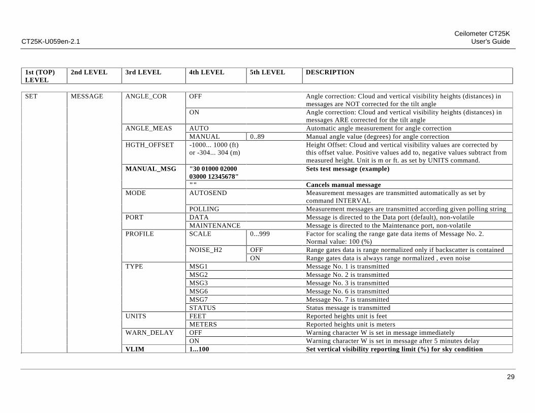
Table 4-1 List of user and advanced level commands. Advanced level commands are marked bold.
1st (TOP)LEVEL
2nd LEVEL 3rd LEVEL 4th LEVEL 5th LEVEL DESCRIPTION
CLOSE Release port for message transmission, i.e. abort command dialogBACK Back to normal user command setRESET NO Do not reset
YES Make full resetSET ALGORITHM DEFAULTS Set default algorithm parameter settings
CONTROL BLOWER ON Turn window conditioner blower ONOFF Turn window conditioner blower OFF
BLOWER MANUAL Set window conditioner blower to manual controlAUTO Set window conditioner blower to automatic control
INHEATER ON Turn internal heater ONOFF Turn internal heater OFF
OUTHEATER ON Turn window conditioner heater ONOFF Turn window conditioner heater OFF
DATA_ACQ AUTOADJ ON Data Acquisition parameters are software controlledOFF Data Acquisition parameters are manual controlled
COMP COARSE Set internal crosstalk compensation setting coarse code valueFINE Set internal crosstalk compensation setting fine code value
INTERVAL 15...120 Data Acquisition: Set interval for measurement and message sending.TRANSMIT POWER_OF_P Set pulse energy input code value
FACTORY INLASER Set pulse energy input code value (at start-up)OUTLASER Set pulse energy target value for software adjustmentRECVALUE Set receiver test reference valueWIN_CLEAN Set clean window reference value
Ceilometer CT25KCT25K-U059en-2.1 User’s Guide
29
1st (TOP)LEVEL
2nd LEVEL 3rd LEVEL 4th LEVEL 5th LEVEL DESCRIPTION
SET MESSAGE ANGLE_COR OFF Angle correction: Cloud and vertical visibility heights (distances) inmessages are NOT corrected for the tilt angle
ON Angle correction: Cloud and vertical visibility heights (distances) inmessages ARE corrected for the tilt angle
ANGLE_MEAS AUTO Automatic angle measurement for angle correctionMANUAL 0..89 Manual angle value (degrees) for angle correction
HGTH_OFFSET -1000... 1000 (ft)or -304... 304 (m)
Height Offset: Cloud and vertical visibility values are corrected bythis offset value. Positive values add to, negative values subtract frommeasured height. Unit is m or ft. as set by UNITS command.
MANUAL_MSG "30 01000 0200003000 12345678"
Sets test message (example)
"" Cancels manual messageMODE AUTOSEND Measurement messages are transmitted automatically as set by
command INTERVALPOLLING Measurement messages are transmitted according given polling string
PORT DATA Message is directed to the Data port (default), non-volatileMAINTENANCE Message is directed to the Maintenance port, non-volatile
PROFILE SCALE 0...999 Factor for scaling the range gate data items of Message No. 2.Normal value: 100 (%)
NOISE_H2 OFF Range gates data is range normalized only if backscatter is containedON Range gates data is always range normalized , even noise
TYPE MSG1 Message No. 1 is transmittedMSG2 Message No. 2 is transmittedMSG3 Message No. 3 is transmittedMSG6 Message No. 6 is transmittedMSG7 Message No. 7 is transmittedSTATUS Status message is transmitted
UNITS FEET Reported heights unit is feetMETERS Reported heights unit is meters
WARN_DELAY OFF Warning character W is set in message immediatelyON Warning character W is set in message after 5 minutes delay
VLIM 1...100 Set vertical visibility reporting limit (%) for sky condition

Ceilometer CT25KUser’s Guide CT25K-U059en-2.1
30
1st (TOP)LEVEL
2nd LEVEL 3rd LEVEL 4th LEVEL 5th LEVEL DESCRIPTION
SET OPER_MODE COMP_MONIT Run internal crosstalk compensation monitor until ESCCONTINUOUS Operation Mode: Continuous measurement modeSTANDBY Standby mode, no measurement unless commanded by START
(initiates one cycle)OPTION SKY_COND ON CODE Activate sky condition option
OFF Deactivate sky condition optionHUMITTER ON Enable humitter option
OPTION HUMITTER OFF Disable humitter optionBLOWER ON Enable blower related status and warning information, needs reset
OFF Disable blower related status and warning informationPORT TIMEOUT 2...60 Timeout for automatic CLOSE of dialog mode. Value in minutes.
Default: 2 minutesMAINTENANCE B300 Set maintenance port bit rate to 300 bits/s
B2400 Set maintenance port bit rate to 2400 bits/sB4800 Set maintenance port bit rate to 4800 bits/sB9600 Set maintenance port bit rate to 9600 bits/s
DATA MODEM BELL_103 300 bits/s modem modeV21 300 bits/s modem modeBELL_212A 1200 bits/s modem modeV22 1200 bits/s modem modeV42_NORMAL 1200-2400 bits/s modem mode, with error correction (V.22bis + V.42)V42_BIS 1200-9600 bits/s modem mode, with error correction and data
compression (V.22bis + V.42bis)OFF Switch modem off and use serial line communication
INTERFACE RS232 Use RS232 serial lineRS422 Use RS422 4-wire serial lineRS485_2W Use RS485 2-wire serial lineRS485_4W Use RS485 4-wire serial line

Ceilometer CT25KCT25K-U059en-2.1 User’s Guide
31
1st (TOP)LEVEL
2nd LEVEL 3rd LEVEL 4th LEVEL 5th LEVEL DESCRIPTION
SET BAUD B300 Set data port serial line baud rate to 300B1200 Set data port serial line baud rate to 1200B2400 Set data port serial line baud rate to 2400B4800 Set data port serial line baud rate to 4800B9600 Set data port serial line baud rate to 9600
SW_STATUS OK Set report / algorithm conflict status bit okUNIT_ID 0...Z Unit Identifier: Alphanumerical character for message and polling
identificationGET ALGORITHM Print values of Algorithm parameters
DMC_SN Print DMC50 board serial numberDATA_ACQ Print settings of Data AcquisitionFACTORY Print values of Factory settingsINFO Print identifying information for this equipment configurationMESSAGE Print Message SettingOPER_MODE Print Operating ModeOPTIONS Print installed modem and active options
PORT Print values of Port settingsSTATUS Print STATUS messageSW_STATUS Print report / algorithm conflict status bitUNIT_ID Print Unit Identification stringVALUE OTHERS ANGLE Print value of tilt angle sensor, range -15...+90 degrees from vertical
POWER_OF_P Print measured value of laser pulse power, units: mV at A-to-Dconverter input
RECVALUE Print measured receiver test valuesRADIANCE Print measured value of background radiance, units: mV at A-to-D
Converter inputWINDOW Print measured value of Window Contamination Monitor, units: mV
at A-to-D Converter input

Ceilometer CT25KUser’s Guide CT25K-U059en-2.1
32
1st (TOP)LEVEL
2nd LEVEL 3rd LEVEL 4th LEVEL 5th LEVEL DESCRIPTION
GET VALUE TEMPERATURE BLOWER Print value of measured blower temperature, units: °CCPU Print value of measured CPU board temperature, units: °CLASER Print value of measured laser temperature, units: °CLENS Print value of measured temperature adjacent to lens, units: °COUTSIDE Print value of measured outside temperature, units: °C
VOLTAGE BCIRCUIT Print status of battery circuit, connected / disconnected = 1/0BATTERY Print value of battery voltage, approx. +13VCHARGE Print value of battery charge voltage, approx. +13VVCA Print value of internal raw voltage, approx. +25VPHV Print value of Receiver high voltage, approx. +200VPFB Print value of Receiver switcher internal feedback voltage, appr +2V
VALUE VOLTAGE P65 Print value of Transmitter high voltage, approx. +65VP18 Print value of general internal supply voltage +18VP13 Print value of Receiver supply voltage +13VP12 Print value of general internal supply voltage +12.5VP5G Print value of general internal supply voltage +5VP5R Print value of Receiver supply voltage +5VM13 Print value of Receiver supply voltage -13VM12 Print value of general internal supply voltage -12.5VM5R Print value of Receiver supply voltage -5VM5G Print value of general internal supply voltage -5V
VERSION Print identifier for Software versionVLIM Print sky condition vertical visibility reporting limit (%)
START Start single-cycle measurement in operation mode STANDBY. Referto command SET OPER_MODE STANDBY.
STOP Stop internal compensation routine

Ceilometer CT25KCT25K-U059en-2.1 User’s Guide
33
4.4 Data Messages
The following standard messages are provided:
Data message No. 1, 2, 3, 6 and 7.
ANet / INet communication with DMX611.
Status message S.
Each port can be set to transmit a specified message automatically.Alternatively the port can be set to transmit the set message only when polledby a predetermined polling string of characters, or the polling string cancontain the message identification.
NOTE
All characters are 7-bit USASCII.
↵ symbolizes Carriage Return+Line Feed (2 characters)throughout this document.
Start-of-Header, Start-of-Text, End-of-Text, CarriageReturn and Line Feed are non-printing characters in mostpractical terminal use.
4.4.1 Data Message No. 1
This message is intended for cloud height/vertical visibility measurementwhen no other measurement information is desired. The message includes themost elementary status information, which enables a host system or operatorto see that no warnings or alarms are present. An example of data messageno.1 is presented below:
(CTA2010J↵ 1st line 11 char.30 01230 12340 23450 FEDCBA98↵ 2nd line 31 char.L↵ 3rd line 3 char.
------------------total 44 characters
Transmission time and size :0.18 s at 2400 baud (10-bit char.)10.6 kbytes/h, 253 kbytes/d, 7.6 Mbytes/mo. at 4 msg./min., uncompressed.

Ceilometer CT25KUser’s Guide CT25K-U059en-2.1
34
Interpretation of the message is as follows :
1ST LINE
Example: (CTA2010J↵
where
( Start-of-Heading characterCT Ceilometers’ identification string; always CTA Unit number 0...9, A...Z20 Software level id 00...991 Message number; this message is always = 10 Spare character for future subclasses of messageJ Start-of-Text Character
2ND LINE
Example: 30 01230 12340 23450 FEDCBA98↵
where
3 First digit of line: detection status as follows:0 No significant backscatter1 One cloud base detected2 Two cloud bases detected3 Three cloud bases detected4 Full obscuration determined but no cloud base detected5 Some obscuration detected but determined to be transparent/ Raw data input to algorithm missing or suspect
0 Second digit of line: Warnings and Alarm information as follows:0 Self-check OKW At least one Warning active, no AlarmsA At least one Alarm active
01230 If detection status is 1, 2 or 3: Lowest cloud base heightIf detection status is 4: Vertical Visibility as
calculatedIf detection status is 0 or 5: /////
12340 If detection status is 2 or 3: Second lowest cloud base height
If detection status is 4: Highest signal detectedIf detection status is 0, 1 or 5: /////
23450 If detection status is 3: Highest cloud base heightIf detection status is 0, 1, 2, 4, 5: /////

Ceilometer CT25KCT25K-U059en-2.1 User’s Guide
35
FEDCBA98 Alarm (A), Warning (W), and internal status information. Each characteris a hexadecimal representation of four bits, altogether 32 bits (b00-b31),with the following breakdown. Interpretation as follows:
F: b31 Laser temperature shut-off (A)b30 Laser failure (A)b29 Receiver failure (A)b28 Voltage failure (A)
E: b27 (spare) (A)b26 (spare) (A)b25 (spare) (A)b24 (spare) (A)
D: b23 Window contaminated (W)b22 Battery low (W)b21 Laser power low (W)b20 Laser temperature high or low (W)
C: b19 Internal temperature high or low (W)b18 Voltage high or low (W)b17 Relative Humidity is > 85 % (option) (W)b16 Receiver optical cross-talk
compensation poor (W)B: b15 Blower suspect (W)
b14 (spare) (W)b13 (spare) (W)b12 (spare) (W)
A: b11 Blower is ONb10 Blower heater is ONb09 Internal heater is ONb08 Units are METERS if ON, else FEET
9: b07 Polling mode is ONb06 Working from batteryb05 Single sequence mode is ONb04 Manual settings are effective
8: b03 Tilt angle is > 45 degreesb02 High background radianceb01 Manual blower controlb00 (spare)
For example, if the battery voltage is too low, the internal heater is on andunits are meters, a warning is given and the second line appears as
0W ///// ///// ///// 00400300.
3RD LINE
L↵ End-of-Text and CRLF

Ceilometer CT25KUser’s Guide CT25K-U059en-2.1
36
4.4.2 Data Message No. 2
Data message no. 2 contains the range and sensitivity normalized backscatterprofile within a range of 0..25000 ft, which makes it suitable for e.g. graphicalplotting of the atmosphere.
Data resolution is 100ft = 30 m with distance, and 16 bits (four hex-ASCIIcharacters) with signal magnitude.
NOTE
Message no. 2 should not be used with slow baud rate andshort data acquisition interval; this may lead to overflowof the transmit buffer. E.g. 300 baud rate requires 45 sec.data acquisition interval with message 2. In case the bufferis filling up, the response time to user command mayextend to minutes.
An example of data message no. 2 is presented below:
(CTA2023J 1st line 11 char.
30 01230 12340 23450 FEDCBA98↵ 2nd line 31 char.
100 N 53 +34 204 146 +2 621 LF7HN1 139↵ 3rd line 44 char.
00047F200000000000000000000000000000000000000050D010000000000000000↵01600FFFFFFFFFFFFFFFFFFFFFFFFFFFFFEFEFEFEFEFEFEFEFEFEFEFDFDFDFDFDFD↵03200FFFFFFFFFFFFFFFFFFFFFFFFFFFFFEFEFEFEFEFEFEFEFEFEFEFDFDFDFDFDFD↵048FDFDFDFDFDFCFCFCFCFCFCFCFCFBFBFBFBFBFBFBFAFBFAFBFBFAFAFBFAF9FAF9↵064FDFDFDFDFDFCFCFCFCFCFCFCFCFBFBFBFBFBFBFBFAFBFAFBFBFAFAFBFAF9FAF9↵080F9FAF9F9F9F9F9F9F9F8F7F8F7F9F8F7F7F8F6F7F7F7F6F6F7F6F7F6F6F6F6F6↵096F9FAF9F9F9F9F9F9F9F8F7F8F7F9F8F7F7F8F6F7F7F7F6F6F7F6F7F6F6F6F6F6↵112F5F5F5F6F5F2F4F5F6F5F5F4F4F4F4F3F4F3F4F5F3F5F4F4F2F3F3F3F3F4F4F3↵128F5F5F5F6F5F2F4F5F6F5F5F4F4F4F4F3F4F3F4F5F3F5F4F4F2F3F3F3F3F4F4F3↵144F2F2EFF1F4F1F2F2F1F3F2F2EFF1EFF0F0EFF1EFF0F1EFF0F0F2F0EFF0EFEFF0↵160F2F2EFF1F4F1F2F2F1F3F2F2EFF1EFF0F0EFF1EFF0F1EFF0F0F2F0EFF0EFEFF0↵176EEF1EFEDEFEEEFEEEEF0EDF0F2EFEDEFEFEFF0EFECECECEEEAF0EDEDECEAEAEA↵192EEF1EFEDEFEEEFEEEEF0EDF0F2EFEDEFEFEFF0EFECECECEEEAF0EDEDECEAEAEA↵208EEF1EFEDEFEEEFEEEEF0EDF0F2EFEDEFEFEFF0EFECECECEEEAF0EDEDECEAEAEA↵224F0ECEFEDF0ECEBEEEDEEE9EAEFF0EEECEAEDECEBEAEEE7EDEAEAEAEBECEAEAEA↵240F0ECEFEDF0ECEBEEEDEEE9EAEFF0EEECEAEDECEBEAEEE7ED0000000000000000↵L↵
4...19 line:16 * 69 = 1104 char.12th line 3 char.------------------total 1193 char.
Transmission time and size :5.0 s at 2400 baud (10-bit char.)143 kbytes/h, 3.44 Mbytes/d, 103 Mbytes/mo. at 2 msg./min., uncompressed.
Ceilometer CT25KCT25K-U059en-2.1 User’s Guide
37
Interpretation of the message is as follows:
1ST LINE
Identical to that of message no. 1 except that the second to last digit whichidentifies the message number is always 2.
2ND LINE
Identical to that of message no. 1
3RD LINE
Example: 100 N 53 +34 204 146 +2 621 LF7HN1 139↵
Measurement parameters are mostly in engineering units. Plus and minussigns are possible. Out-of-Range is indicated by slashes (/////). Contents:
100 Parameter SCALE, 100 (%) is normal (0...999 possible)N measurement mode; N = Normal,
(C = Close range, not available in CT25K)53 laser pulse energy, % of nominal factory setting (0...999)+34 laser temperature degrees C (-50...+99)204 receiver sensitivity, % of nominal factory setting (0...999)146 window contamination, millivolts at internal ADC input (0...2500)+2 tilt angle, degrees from vertical (-15...+90)621 background light, millivolts at internal ADC input (0...2500)LF7HN1 measurement parameters (pulse Long/Short, freq F (const.), pulse qty
47+1, gain High/Low, bandwidth Narrow/Wide, sampling 10/20 MHz)139 SUM of detected and normalized backscatter, 0...999.
Multiplied by scaling factor times 104. At scaling factor 100 theSUM range 0...999 corresponds to integrated backscatter
0...0.0999 srad-1
4TH...19TH LINE
Backscatter profile, sensitivity and range normalized, at 100 ft = 30 m
resolution, normally scaled to units of (10000·srad·km)-1
Example of 8th line:
064FDFDFDFDFDFCFCFCFCFCFCFCFCFBFBFBFBFBFBFBFAFBFAFBFBFAFAFBFAF9FAF9↵
where:064 is start distance (height) of line backscatter data items;
decimal, unit is 100ft = 30m = 200ns (two-way)
FDFC, FBFA, ... are 16 four-character data items per line, at 100ft =30m = 200ns resolution; 16-bit HEX-ASCII; msbnibble and bit first. 2's complement. Data is rangeand sensitivity normalized backscatter, units
(10000·srad·km)-1 unless otherwise scaled byparameter SCALE

Ceilometer CT25KUser’s Guide CT25K-U059en-2.1
38
20TH LINE
L↵ End-of-Text and CRLF.
4.4.3 Data Message No. 3
This message contains a line which has one bit for each range gate at 100 ftresolution. It is intended for printer-type black-and-white graphical recorderssuch as Vaisala DR21, DR23, DD50 with printer, etc. The message is derivedfrom Message no. 2 by setting a threshold for the range and sensitivitynormalized backscatter profile and reporting signal exceeding this thresholdas a 1, and otherwise as a 0. The bit line gets split into groups of foursuccessive range gates, which are then transmitted as a string of 64hexadecimal characters 0...F.
Message format example:
(CTA2033J↵ 1st line 11 char.30 01230 12340 23450 FEDCBA98↵ 2nd line 31 char.00002204FFEFFF8C00000000627EEFFF310000000335A0BFFFFF100000000000↵
3rd line 66 char.L↵ 4th line 3 char.
-------------------total 111 characters
Transmission time and size :0.46 s at 2400 baud (10-bit char.)26.64 kbytes/h, 639 kbytes/d, 19.18 Mbytes/mo. at 4 msg./min.,uncompressed.
Message interpretation:
1ST LINE
Identical to that of Message No. 1 except that the second to last digit whichidentifies the message number, is always 3.
2ND LINE
Identical to that of Message No. 1
3RD LINE
Example:
00002204FFEFFF8C00000000627EEFFF310000000335A0BFFFFF100000000000↵
64 hexadecimal characters 0...F, each bit in its binary format representing oneof four subsequent range gates at 100 ft (30 m) resolution. Bit is set to "1" ifits internal unscaled value (in units of (10,000 km srad)-1, ref. message no. 2)exceeds 1,000 * 100/SCALE , i.e. maximizing the value of parameter SCALE to

Ceilometer CT25KCT25K-U059en-2.1 User’s Guide
39
999 minimizes the threshold, and thus, maximizes recording sensitivity to abackscatter value of 100 / (10,000 km srad).
4TH LINE
Identical to the 3rd line of message no. 3.
4.4.4 Data Message No. 4
Data message no. 4 is not in use.
4.4.5 Data Message No. 5
Data message no. 5 is not in use.
4.4.6 Data Message No. 6
Message number 6 is similar to message number 1 but extended with a skycondition line (section 5.4.). For interpretation, see paragraph 4.4.1.
Message number 6 format example:
(CTA2060J↵ 1st line 11 char.30 01230 12340 23450 FEDCBA98↵ 2nd line 31 char. 3 055 5 170 0 /// 0 ///↵ 3rd line 30 char.L↵ 4rd line 3 char.
------------------total 75 characters
Transmission time and size :total 75 characters=> 0.31 s at 2400 baud (10 bit char.)=> 18.0 kBytes/h, 432 kBytes/d, 12.7 MBytes/mo. at 4 msg/min,uncompressed
Message interpretation :
LINES 1 and 2 are indentical to that of Message number 1.
LINE 3
Example: 3 055 5 170 0 /// 0 ///
where
3 The first number of line: detection status as follows:
0 ... 8 Cloud amount of the first layer in oktas
9 Vertical visibility
-1 Data missing or the ceilometer is in standby mode
99 Not enough data (after start-up)

Ceilometer CT25KUser’s Guide CT25K-U059en-2.1
40
055 The second number of line: Height of the 1st cloud layer (5 500 ft or 550 m depending on feet or meter selection)
5 The third number of line: Cloud amount of the 2nd layer in oktas
170 The fourth number of line: Height of the 2nd cloud layer (17 000 ft or 1 700 m depending on feet or meter selection)
0 The fifth number of line: Cloud amount of the 3rd layer in oktas
/// The sixth number of line: Height of the 3rd cloud layer
0 The seventh number of line: Cloud amount of the 4th layer in oktas
/// The eighth number of line: Height of the 4th cloud layer
The reporting resolution is 100 ft or 10 m depending on feet or meterselection. If the cloud amount is zero the corresponding layer height is "///".
4.4.7 Data Message No. 7
Message number 7 is similar to message number 2 but extended with a skycondition (section 5.4) line. The sky condition line is identical to that ofmessage number 6. For interpretation, see paragraphs 4.4.2 and 4.4.6. Belowis an example of message number 7.
(CTA2070J↵50 ///// ///// ///// 00000200↵100 N 101 +19 90 200 +6 21 LF7HN1 27↵0000003000400030003000300020003000300030001000100010000000000000000↵0160000000000000000000000000000FFFF00010000000200000001FFFFFFFE0000↵032FFFC0000FFFE00000001FFFF000000010000FFFE000000020000000000000004↵0480000FFFE00030007FFFE0000FFFEFFFE000100050011FFFF000000000000FFFE↵0640001FFFEFFFF0000000000020000000100000000FFFF00010003FFFEFFFE0000↵08000010000FFFF0002FFFEFFFEFFFEFFFD000000020001FFFEFFFD000000000001↵0960002000300000000000000010000FFFF000000000000FFFC0000FFFFFFFEFFFF↵1120000000000000001FFFCFFFF00000002FFFE00000000FFFFFFFF00010000FFFE↵128000000000000000000010000FFFFFFFF00000000FFFE00000000000300000001↵144000200010000FFFFFFFFFFFEFFFEFFFFFFFF00000000FFFE0001FFFFFFFF0000↵160FFFE0000FFFE0015004300B200B300E300540022000C0030FFFF000000000001↵176FFFF000000000001FFFC00000000000000000001FFFF0000000100000001FFFD↵192000000000000FFFE00000000000100010001000000000001FFFFFFFFFFFFFFFE↵2080000FFFE0000FFFE00000001FFFF000000020000000000010000FFFFFFFF0001↵22400000000FFFE000000020001FFFEFFFFFFFEFFFF000000000001000100010001↵240FFFE0000FFFE0000FFFFFFFD0000000400000001FFFF00000000000000000000↵ 1 028 5 135 0 /// 0 ///↵L↵
Transmission size and time for Msg7 is :
total 1223 characters=> 5.1 s at 2400 baud (10 bit char.)=> 147 kBytes/h, 3.52 MBytes/d, 106 MBytes/mo. at 2 msg/min,
uncompressed

Ceilometer CT25KCT25K-U059en-2.1 User’s Guide
41
NOTE
"Not enough data", i.e. detection status 99, is reported after a start-up until theunit has operated for 25 minutes. "Data missing", i.e. detection status -1, isreported if more than 25% of gathered data is considered invalid due to ahardware failure.
4.4.8 (Spare)
4.4.9 (Spare)
4.4.10 DMX611 operation (option)
The DMX611 serves as an interface between CT25K buss structure andVaisala proprietary ANet and INet busses.
The DMX611 converts CT25K data into binary format. After receiving a pollrequest, the DMX611 sends an answer packet containing the requestedCT25K data. While both the poll and answer messages are in hexadecimalbinary format, the user interface is offered by the Testset. The Testset may bea hand held device or a software application. Refer to AWOS 2000Maintenance manual for operational instructions.

Ceilometer CT25KUser’s Guide CT25K-U059en-2.1
42
4.4.11 Status Message "S"
The Status Message displays internal monitoring of the whole unit includingprevailing parameter values for voltages, receiver and transmitter,temperatures, environmental factors, and internal heating. The message ismeant mainly for testing and maintenance purposes. The Status Message isdisplayed by the command GET STATUS.
An example of the status message is presented below:
(CTA38S0J↵0W ///// ///// ///// 00400200↵VOLTAGES (UNIT 0.1V)↵P12 125 M12 -126 P5G 54 M5G -54 VCA 225↵P13 128 M13 -124 P5R 50 M5R -50 BAT*098↵P18 178 PHV 2306 PFB 17 P65 674 CHA 144↵↵RECEIVER TRANSMITTER↵GAIN H PLEN L↵BAND N PQTY 64K↵SAMP 10MHz OUT 1416mV↵SENS OK SENS 101%↵COMP 013 125 IN 190↵↵TEMPERATURES ENVIRONMENT↵BLOWER +20C WINDOW 210mV 102%↵CPU +34C RADIANCE +60mV↵LASER +29C ANGLE +3DEG (M)↵LENS +34C HUMIDITY NONE↵OUTSIDE +23C↵INHEATER ON OUTHEATER OFF BLOWER OFF↵L↵
NOTE
An asterisk (*) in front of a variable indicates that analarm or warning limit of that variable is exceeded. In theexample above the battery voltage is too low.
(M) is shown after the ANGLE value only if the manualangle setting is used.
Interpretation of the status message is as follows:
1ST LINE
Identical to that of message no. 1 except that the second to last characterwhich identifies the message number, is always S.
2ND LINE
Identical to that of message no. 1

Ceilometer CT25KCT25K-U059en-2.1 User’s Guide
43
LINES 3...6
Measured internal voltages in units of 0.1V, as follows:
BAT Battery voltage, e.g. 098CHA Battery charge voltage, e.g. 144VCA Internal raw voltage, e.g. 225PHV Receiver high voltage, e.g. 2306PFB Rec. switcher feedback voltage, e.g. 17P65 Transmitter high voltage, e.g. 674P18 General internal supply voltage, e.g. 178P13 Receiver supply voltage, e.g. 128P12 General internal supply voltage, e.g. 125P5G General internal supply voltage, e.g. 54P5R Receiver supply voltage, e.g. 50M13 Receiver supply voltage, e.g. -124M12 General internal supply voltage, e.g. -126M5R Receiver supply voltage, e.g. -50M5G General internal supply voltage, e.g. -54
LINES 8...13
Prevailing Receiver and Transmitter settings and variables as follows:
RECEIVER GAIN H or L Gain is High or LowBAND N or W Bandwidth is Narrow or
WideSAMP 10MHz Sampling rate is 10 MHzSENS OK Receiver sensitivity OK
compared to factorysetting
COMP 13 125 Internal crosstalkcompensation settingcodes, coarse (013) andfine (125)
TRANSMITTER PLEN L or S Pulse length is Long orShort
PQTY 64K Pulse quantity is 64x1024OUT 1416mV Laser pulse energy
measured by OpticsMonitor is 1416 mV atMonitoring A-to-DConverter input.
SENS 101% Measured pulse energy is101 % of nominal value
IN 190 Pulse energy controlinput code is 190

Ceilometer CT25KUser’s Guide CT25K-U059en-2.1
44
LINES 15...20
Temperature and environment variables as follows:
TEMPERATURE BLOWER +20C Temperatue measured at theWindow Conditioner blowerairfow exit, e.g. +20 deg C
CPU +34C Temperature on themicroprocessor (CPU) Board,e.g. +34 deg C
LASER +29C Temperature measured at thelaser diode, e.g. +29 deg C
LENS +34C Temperature measuredadjacent to the lens, e.g.+34 deg C
OUTSIDE +23C Temperature measured by theexternal sensor (atconnectors), e.g. +23 deg C
ENVIRONMENT WINDOW 210mV102%
Value of windowcontamination measurement,e.g. 210 mV, and ratio inper cent compared to factorysetting, e.g. 102 %
RADIANCE +60mV Value of background radiancemeasurement, e.g. 60 mV
ANGLE +3DEG Value of tilt angle relativeto vertical, e.g. +3degrees. Positive valuemeans that door of the unittilts towards ground.
HUMIDITY NONE (Relative Humidity in percent inside the ceilometerif sensor is furnished)
LINE 21
Status of Internal Heater (INHEATER ON/OFF), Window Conditioner Heater(OUTHEATER ON/OFF), Window Conditioner Blower (BLOWERON/OFF).
LINE 22
L↵ End-of-Text and CRLF

Ceilometer CT25KCT25K-U059en-2.1 User’s Guide
45
4.4.12 Manual Message
The ceilometer can be set to transmit user defined cloud heights and statusinformation. The user can set a cloud message in the format of line 2 of anyreal cloud message (e.g. Msg 1). The message must be between quotationmarks, see example. This message is volatile. The manual message commandis behind the password "advanced". Below is an example of a manualmessage:
CEILO>ADVANCED
PASSWORD ACCEPTED !
CEILO>set message manual_msg "30 00200 01000 05000 00000000"
MANUAL MESSAGE: 30 00200 01000 05000 00000000
If the given message does not have the correct format, it is not accepted andan error message will follow. To return to the normal measurement mode,give an empty string :
CEILO>SET MESSAGE MANUAL_MSG ""
MANUAL MESSAGE NOT ACCEPTED
USE FORMAT: "30 00100 02000 15000 00000000"
MESSAGE MODE IS NORMAL MEASUREMENT MODE
The manual message is intended for testing purposes. After reset the normalcloud detection mode takes effect.
4.5 Polling mode
A port can be set to transmit a message only when polled by a predeterminedpolling string of characters. The polling string can contain the messageidentification.
The CT25K unit can be assigned an identification of one character digit orletter. The factory setting is 0 (zero). The polling mode is activated with thecommand:
CEILO>SET MESSAGE MODE POLLING
and return to normal autosend mode is done with command
CEILO>SET MESSAGE MODE AUTOSEND.
The polling string format is
<Enq> CT id no ↵
Ceilometer CT25KUser’s Guide CT25K-U059en-2.1
46
where
Enq is character ENQUIRE = ASCII 05H = control-ECT is fixed ceilometer identifier id is identification character, 7-bit printable ASCII character.No is optional message identifier 1, 2, 3, 6, 7, S↵ ENTER (Carriage Return) + Line Feed
Polling command examples :
< Enq > CT11<Enter> Message 1 from ceilometer nr.1< Enq > CT12<Enter> Message 2 from ceilometer nr.1< Enq > CT1S<Enter> Status message from ceilometer nr.1
NOTE
If the id character in a polling string is replaced with ablank space, all ceilometers on the line will respond.Accordingly, if No is a blank space, CT25K sends thedefault message.
4.6 Prevailing parameter settings
The prevailing control and parameter settings that chiefly determine operationcan be seen by the following GET commands. Shown parameter values areequal to standard factory settings but may vary depending on installation inquestion. Operator input is marked in CAPITAL (Times) letters after thecommand prompt CEILO> and the Ceilometer response under the operatorinput as COURIER font.
In case you want to change parameter values see paragraph 3.4 for settings ofuser programmable parameters.
CEILO>GET ALGORITHM
NOISE SCALE: 1.7MINIMUM SUM: 30MINIMUM EXTCO: 6.0
CEILO>GET DATA_AQC
AUTOADJUSTMENTS: ONDATA-ACQ. INTERVAL: 15 SEC.RECEIVERGAIN: H *BANDWIDTH: NSAMPLING RATE: 10 MHzTRANSMITTERLENGTH OF PULSE: L *POWER OF PULSE: 188 *QUANTITY OF PULSES: 64KCOMPENSATIONCOARSE COMPENSATION: 12 *FINE COMPENSATION: 109 *
Ceilometer CT25KCT25K-U059en-2.1 User’s Guide
47
CEILO>GET FACTORY
FACTORYBEAMSPLITTER: 96% **IN LASER: 185 **OUT LASER: 1200 **COARSE COMP.: 13 **FINE COMP.: 125 **RECEIVER TEST VALUE: 350 **CLEAN WINDOW: 200mV **
CEILO>GET MESSAGE
MESSAGEANGLE CORRECTION: ONHEIGHT OFFSET: 0NOISE H2 COMPENSATION: OFFPROFILE SCALE: 100%PORT: DATATYPE: MSG1UNITS: FEETMODE: AUTOSEND
CEILO>GET OPER_MODE
OPERATION MODE: CONTINUOUS
CEILO>GET PORT
MAINTENANCE PORT BAUDS: 2400, E71DATA PORT BAUDS: 300, E71MODEM: CCITT (300)MODEM STATUS: ONYOU ARE USING: MAINTENANCE PORT
CEILO>GET UNIT_ID
UNIT ID: 0
NOTE
* Individual values are automatically adjusted by thesoftware.
** Individual original factory settings or updated originalsettings in conjunction with subassembly replacement.
4.7 Manual angle setting
The automatic tilt angle measurement can be disabled and replaced with amanual value. To set the manual angle value type :
CEILO>ADVANCED
PASSWORD ACCEPTED !
CEILO>SET MESSAGE ANGLE_MEAS MANUAL 5
MANUAL ANGLE: 5
To check the current state of tilt angle setting, get the status message :

Ceilometer CT25KUser’s Guide CT25K-U059en-2.1
48
CEILO>GET STATUS
VOLTAGES (UNIT 0.1V)P12 130 M12 -122 P5G 53 M5G -54 VCA 220P13 126 M13 -121 P5R 49 M5R -48 BAT 121P18 176 PHV 2755 PFB 20 P65 769 CHA 121
RECEIVER TRANSMITTERGAIN H PLEN LBAND N PQTY 64KSAMP 10MHz OUT 1270mVSENS OK SENS 100%COMP 013 125 IN 190
TEMPERATURES ENVIRONMENTBLOWER +20C WINDOW 200mV 100%CPU +32C RADIANCE 60mVLASER +28C ANGLE +5DEG (M)LENS +32C HUMIDITY NONEOUTSIDE +20CINHEATER OFF OUTHEATER OFF BLOWER OFF
(M) after the angle value indicates the use of a manual value.

Ceilometer CT25KCT25K-U059en-2.1 User’s Guide
49
5. FUNCTIONAL DESCRIPTION
5.1 Theory of Operation
Basic Principle of Operation
The operating principle of the CT25K Ceilometer is based on measurement ofthe time needed for a short pulse of light to traverse the atmosphere from theTransmitter of the Ceilometer to a backscattering cloud base and back to theReceiver of the Ceilometer.
With the speed of light being:
c = 2.99 x 10⁸ m/s (= 186 000 miles per second)
A reflection from 25,000 ft will be seen by the receiver after
t = 50.9 µs
The general expression connecting time delay (t) and backscattering height (h) is
h = ct/2
where c is the speed of light.
Practical Measurement Signal
Generally, particles at all heights backscatter light, and so the actual returnsignal may look like that shown in Figure 5-1.
Figure 5-1 Typical Measurement Signal
The instantaneous magnitude of the return signal will provide information onthe backscatter properties of the atmosphere at a certain height. From thereturn signal, information about fog and precipitation, as well as cloud, can bederived. Since fog and precipitation attenuate the light pulse, the cloud basesignal will appear lower in magnitude in the return echo. However, the fogand precipitation information also provides data for estimating this attenuationand computing the necessary compensation, up to a limit.

Ceilometer CT25KUser’s Guide CT25K-U059en-2.1
50
In its normal full-range operation the CT25K ceilometer digitally samples thereturn signal every 100 ns from 0 to 50 µs, providing a spatial resolution of 50feet from ground to 25,000 feet distance. This resolution is adequate formeasuring the atmosphere, since visibility in the densest clouds is in the orderof 50 feet.
Noise Cancellation
For safety and economic reasons, the laser power used is so low that the noiseof the ambient light exceeds the backscattered signal. To overcome this, alarge number of laser pulses are used, and the return signals are summed. Thedesired signal will be multiplied by the number of pulses, whereas the noise,being random, will partially cancel itself. The degree of cancellation for white(Gaussian) noise equals the square root of the number of samples; thus, theresulting signal-to-noise ratio improvement will be equal to the square root ofthe number of samples. However, this processing gain cannot be extended adinfinitum since the environment changes. For example, clouds move.
Return Signal Strength
The instantaneous return signal strength is in general form (the Lidarequation):
∫ ′′−
⋅⋅⋅⋅=
z
zdz
ezz
AcEoz 0
)(2
2r )(
2)(P
σ
β
where
Pr(z) is the instantaneous power received from distance z [W = Watt].
EO is the effective pulse energy (taking all optics attenuation intoaccount) [J = Joule = Ws = Watt - second].
c is the speed of light [m/s = meters per second].A is the receiver aperture [m2].z is the distance in question [m].ß(z) is the volume backscatter coefficient at distance z [m-1srad-1,
srad = steradian].
ez dz
z
− ′ ′∫2
0
σ ( )
is the two-way atmospheric transmittance and accounts for theattenuation of transmitted and backscattered power byextinction at various distances (z') between transceiver anddistance in question (z). The expression equals 1 in a clearatmosphere (i.e., no attenuation).

Ceilometer CT25KCT25K-U059en-2.1 User’s Guide
51
Height Normalization
Assuming a clear atmosphere, it can be seen that the power is inverselyproportional to the square of the distance or height i.e., the strength of a signalfrom 10,000 ft is generally one-hundredth of that from l,000 ft.
The height-square dependence is eliminated by multiplying the valuemeasured with the square of the height (height normalization). However,noise, being height-independent from a measurement point of view, will thenbe correspondingly accentuated with increasing height.
The Backscatter Coefficient
The volume backscatter coefficient, ß(z), of the Lidar Equation represents theportion of light which is reflected back towards the Ceilometer from adistance z (e.g., by water droplets). It is obvious that the denser a cloud is,the stronger the reflection will be. The relationship can be expressed as:
ß(z) = k·σ(z)
where
k is a "constant" of proportionality.σ(z) is the extinction coefficient (i.e., the attenuation factor in a
forward direction).
The extinction coefficient relates to visibility in a straightforward manner. Ifvisibility is defined according to a 5 % contrast threshold (WorldMeteorological Organization definition for Meteorological Optical RangeMOR, equals daylight horizontal visibility), then
σ = 3 / V
where
σ is the extinction coefficientV is MOR visibility (5 % contrast)
The "constant" of proportionality, k, also called the Lidar Ratio, has beensubjected to a lot of research. Although the Lidar Equation can be solvedwithout knowing its value, it must remain constant with height if accurateestimates of the extinction (or visibility) profile are to be made.
It has been found that in many cases, k can be assumed to equal 0.03, tendingto be lower in high humidities, to 0.02; and higher in low humidities, to 0.05.However, in e.g. precipitation of various kinds, k will have a wider range ofvalues.
Assuming a value 0.03 (srad-1) for k and visibility in clouds being in the rangePIWJLYHVWKHUDQJHRIYDOXHIRU
= 0.0006...0.006 m-1srad-1 = 0.6...6 km-1srad-1

Ceilometer CT25KUser’s Guide CT25K-U059en-2.1
52
Extinction Normalization and Vertical Visibility
Any fog, precipitation, or similar obstruction to vision between ground andcloud base may attenuate the cloud base signal and produce backscatter peaksthat far exceed that from the cloud. Virtually any backscatter height profile ispossible, up to some physical limits. To distinguish a significant cloud returnsignal, the attenuation of fog, precipitation, etc., has to be taken into accountby normalizing with regard to extinction. The profile thus obtained isproportional to the extinction coefficient at various heights, and enables theuse of fairly straightforward threshold criteria to determine what is cloud andwhat is not.
By assuming a linear relationship between backscatter and extinctioncoefficient according to the previous formula and that the ratio, k, is constantover the range observed, it is possible to obtain an extinction coefficientprofile through a mathematical computation. This is also called inverting thebackscatter profile to obtain the extinction coefficient profile, and answers thequestion, "What kind of extinction coefficient profile would produce thebackscatter profile measured?".
No assumption as to the absolute value of the ratio, k, needs to be made if k isconstant with height. The assumptions that have to be made are fairly truthful,and in any case accurate enough for the purpose of cloud detection.
Likewise, the inversion is also independent of several instrumentaluncertainties including transmitted power and receiver sensitivity.
An estimate of Vertical Visibility can easily be calculated from the extinctioncoefficient profile because of the straightforward extinctioncoefficient-to-visibility relationship, provided that a constant contrastthreshold is assumed. Visibility will simply be that height where the integralof the extinction coefficient profile, starting from ground, equals the naturallogarithm of the contrast threshold, sign disregarded.
Tests and research have, however, shown that the 5 % contrast thresholdwidely used for horizontal measurement is unsuitable for verticalmeasurement if values close to those estimated by a ground-based observerare to be obtained.
The CT25K uses a contrast threshold value which, through many tests, hasbeen found to give Vertical Visibility values closest to those reported byground-based human observers. A wide safety margin is obtained with regardto pilots looking down in the same conditions since the contrast objects,especially runway lights, are much more distinct on the ground.

Ceilometer CT25KCT25K-U059en-2.1 User’s Guide
53
5.2 Technical Description
5.2.1 General
Figure 5-2 below shows the internal layout of the Measurement Unit and thefollowing figure 5-3 the subassembly interconnections. Summary of part num-bers and subassemblies is listed in Table 5-1. The technical description is splitinto subparagraphs according to Unit Block Diagram illustrated in Fig. 5-4.For more detailed block diagrams and descriptions, see corresponding sub-paragraphs.
DMF51 FRAME:
CTT21 LASERTRANSMITTER
CTR21 RECEIVER
CT3675TILT ANGLE SENSOR
CT25039INTERNAL HEATERSSUBASSEMBLY
CTB22 OPTICALSUBASSEMBLY
CT35042 STANDARD WINDOW ASSEMBLY
BATTERY 4592 ANDCT3681 BATTERY SWITCHSUBASSEMBLYCTP241 LINE & POWER
INTERFACE SUBASSEMBLY, AC
9412-035
DMC50B PROCESSOR BOARD
DPS52 DC CONVERTER BOARD
MODEM BOARD(OPTIONAL)
DCT51 CEILOMETERINTERFACE BOARD
CTL21 OPTICS MONITOR
Figure 5-2 Measurement Unit Components

Ceilometer CT25KUser’s Guide CT25K-U059en-2.1
54
Figure 5-3 Subassembly Interconnections
Table 5-1 Parts List
PART NO. DESCRIPTION NOTES
CT15035 ENCLOSURECT35042 STANDARD WINDOWCT35043 TROPICS WINDOW Specified at orderCTP241 LINE & PWR INTERFACE
SUBASSEMBLY, AC4592 BATTERY

Ceilometer CT25KCT25K-U059en-2.1 User’s Guide
55
CT25039 INTERNAL HEATERSSUBASSEMBLY
CT3675 TILT ANGLE SENSORCTB22 OPTICAL SUBASSEMBLYCTT21 LASER TRANSMITTERCTR21 RECEIVERCTL21 OPTICS MONITORCT25015 COMPENSATION FIBERDMF51 BOARD FRAMEDMC50B PROCESSOR BOARDDPS52 DC CONVERTER BOARDDCT51 CEILOMETER INTERFACE BOARDDMX55 MODEM BOARD Specified at orderDMX50 MODEM BOARD Specified at orderDM35945 DMX50 CONNECTION ADAPTERDMX611 ANET BUS INTERFACE Specified at orderCT3681 BATTERY SWITCH SUBASSEMBLYCT3696 COAXIAL CABLECT4697 OPTICS MONITOR CABLECT1679 SHIELDCT2614 BLOWER 230 VAC Specified at orderCT2688 BLOWER 115 VAC Specified at orderCT25106 PEDESTAL, metal Specified at orderCT2665 PEDESTAL, fiberglass Specified at orderCT3839 POWER LINE CABLECT3838 DATA CABLECT3709 POWER TERMINATION BOX Specified at orderCT3707 SIGNAL TERMINATION BOX Specified at orderPSION3 MAINTENANCE TERMINAL Specified at orderCT3840 TERMINAL CABLE Specified at orderCT35198 PC TERMINAL CABLE Specified at order17430 DOOR KEY SOUTHCO E3-3CT45155 ALLEN KEY 6mmCT25KWBK WEDGE BOLT KITCT25184 OPTICAL TERMINATION HOOD Specified at orderCT35022 SHOCK ABSORBER Specified at order
5.2.2 LIDAR Measurement
Refer to Block Diagram in Figure 5-4. Top level control resides in thesoftware of Processor Board DMC50B. This determines what settings are tobe used for the measurement. The settings are written by the software intoCeilometer Interface Board DCT51, which then carries out the actualmeasurement autonomously. When the measurement is complete, an interruptis issued from the DCT51 to the DMC50B, upon which the accumulatedmeasurement backscatter raw data profile is fetched by the DMC50B into itsRAM for the algorithmic processing.

Ceilometer CT25KUser’s Guide CT25K-U059en-2.1
56
Normal (full range) mode characteristics:Laser pulse 100 nsEnergy 1.6 µJRepetition rate 5.57 kHzNumber of pulses 65,536Measurement time 11.7 sReceiver on High GainBandwidth 3 MHzSampling at 100 ns500 useful samples per laser pulse,Measurement range 0...25,000 ft. (0...7.5 km)
Figure 5-4 Block Diagram of Operational Units
In addition, there is another mode for carrying out a simulated measurementwithout laser, with the Light Emitting Diode (LED) of the Optics MonitorCTL21 acting as the simulated backscatter. This mode serves for testing thewhole receiver section.

Ceilometer CT25KCT25K-U059en-2.1 User’s Guide
57
When the measurement starts, the Timing and Control logic of the DCT51starts issuing trigger pulses to the Laser Transmitter CTT21 at the specifiedrepetition rate. At each trigger pulse the transmitter sends out one laser pulse.This laser pulse gets collimated by the lens into a near-parallel beam of light.As this short laser beam traverses the atmosphere, particles cause scatter inthe backward direction, a part of which hits the lens and gets focussed by it.The beamsplitter reflects a fixed fraction of it through the InfraredInterference Filter onto the Avalanche Photodiode (APD) of the ReceiverCTR21. The Infrared Interference Filter eliminates all background light noiseoutside the laser wavelength band.
The APD transforms the backscatter photons into electrical current at a fixedratio. This current gets amplified in the transimpedance-type ReceiverAmplifier to a voltage, which is fed into the Flash Analog-to-DigitalConverter (ADC) of the Ceilometer Interface Board DCT51. This ADCconverts the analog voltage to 8-bit digital bytes at the specified samplingrate. These digital samples then get added into the First-In-First-Out (FIFO)register of the DCT51. This FIFO is cleared to all-zeroes before start; its datacontent is rotated so that a sample from a specific distance (specific delaytime after the laser pulse launch) always gets summed into the same rotatingand accumulating register location. Thus the sequential summing of newsamples gradually creates a high-resolution digital image of the backscatterprofile. Noise, being random, increases only in proportion to the square rootof the number of samples, whilst the effective signal increases in directproportion to the number of samples. Thus, the final digital profile will revealproperties of the atmosphere that couldn’t be seen from an instantaneoussignal.
At the end of the set number of pulses the DCT51 issues an interrupt to theDMC50B, upon which the software fetches the digital profile to its RAM forthe algorithmic processing. After processing, the measurement result is readyfor message transmission through the data link to the equipment it connectsto.
In conjunction with the backscatter measurement the laser pulse energy is alsomeasured by the Optics Monitor CTL21 photodiodes. The measured value isused by the algorithm for normalizing the profile into the right magnitude, foradjusting the laser voltage by the Digital-to-Analog Converter (DAC) placedon the DCT51, and ultimately, for warning or alarming of loss of laser power.
During the exit of the laser pulse, a small fraction of energy is also reflectedback into the receiver by the optics surfaces of the unit. Due to thetremendous sensitivity of the receiver, this optical cross-talk could seriouslydistort the profile, and therefore it needs to be neutralized. This is done by asecondary APD, which gets its input from an optical fiber light guide placedso that it only sees the outgoing laser pulse but not the backscatter. The twoAPD’s are connected in a half-bridge configuration, whereby most of theoptics cross-talk signal is substracted from the measurement signal. For bestpossible balancing of the bridge, the compensating APD gain is undersoftware control through the DAC of the DCT51. The backscattermeasurement sampling actually starts before the launch of the laser pulse, and

Ceilometer CT25KUser’s Guide CT25K-U059en-2.1
58
thus the resulting distortion is visible to the software in the raw measurementprofile, and this is iteratively kept within limits.
5.2.3 Internal Monitoring and Control
All essential subassembly functions are monitored continuously to ensuremeasurement accuracy and reliability. Temperature, laser performance etc. ismeasured by sensors and transferred to Processor Board DMC50B, convertedfrom analog to digital by its Monitor A-to-D Converter and further analyzedby the processor software.
Warning and Alarm limits are defined in software through parameter settings.In case a malfunction has been detected, i.e. the limits have been exceeded,the software sends warning and alarm messages which can be seen by theSTATUS message (Paragraph 4.4.11)
5.3 Module Descriptions
5.3.1 Optical Subassembly CTB22
Figure 5-5 Optical Subassembly CTB22 with Optics Monitor,Transmitter and Receiver Subassemblies

Ceilometer CT25KCT25K-U059en-2.1 User’s Guide
59
Description
The optical subassembly consists of the following major units: the conicaloptical tube with fixture for the lens, a precise beam integrator block at thelower end including a beamsplitter and a narrow-band filter, and a connectionflange for the laser transmitter and receiver subassemblies.
The receiver and transmitter subassemblies are factory-aligned and focused tothe optimum. They can be replaced any time by new assemblies without needfor readjustment. The adjustment necessary for the compensation of theoptical crosstalk after replacement of the receiver or transmitter subassemblycan be made by means of a graphical presentation on a maintenance terminal.
At the upper end of the optical tube is the Optics Monitor for control of thelaser performance, window contamination and temperature.
5.3.2 Laser Transmitter CTT21
Figure 5-6 CTT21 Block Diagram
Description
An unregulated supply voltage P65 is brought to the Laser Transmitter CTT21and adjusted to a suitable level by means of an internal voltage regulator. Thelaser diode of the subassembly is supplied with this regulated high voltage. Atrigger pulse is routed through a transformer to the trigger electrode of theswitching thyristor for driving a current pulse through the laser diode. Aspecial pulse-forming network makes this current pulse near-rectangular. A

Ceilometer CT25KUser’s Guide CT25K-U059en-2.1
60
small control circuit with a temperature sensor and a heating element ensuresthe correct laser temperature. The laser temperature is also routed to theCeilometer Interface Board DCT51 and Processor Board DMC50B forinternal monitoring.
WARNING
Dangerous voltages are present in this instrument. Useextreme caution when handling, testing, and adjusting.
Laser safety
To guarantee the eye safety of the laser equipment, the cable connecting thesubassembly is short, permitting operation only when the installation iscomplete. For removing the laser transmitter subassembly, the cable betweenthe transmitter and the laser interface board must be disconnected first.
5.3.3 Receiver CTR21
Figure 5-7 CTR21 Block Diagram
The Receiver subassembly CTR21 consists of two identical avalanche photodiodes (APDs). The second APD compensates most of the optical cross-talkappearing in the lens system through signal reflection by means of a half-bridge connection. The first APD receives the actual measuring signal andsends the pulse current through a transimpedance amplifier with selectablegain. At the output of this amplifier the signal is a voltage signal transferredfurther through a filter with a frequency limit of 15 MHz to a second signalamplifier. According to the operating mode the signal goes further to a newamplifier stage or to a combined additional filter with a frequency limit of 3MHz and an amplifier.
The amplifier gain is selected by the system automatically so that the smallestnoise signal appearing in the measurement signal is bigger than the resolutionof the flash AD converter of the Ceilometer Interface Board DCT51. Thebiggest measurement signal must not exceed the full measurement range of
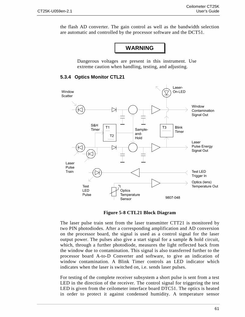
Ceilometer CT25KCT25K-U059en-2.1 User’s Guide
61
the flash AD converter. The gain control as well as the bandwidth selectionare automatic and controlled by the processor software and the DCT51.
WARNING
Dangerous voltages are present in this instrument. Useextreme caution when handling, testing, and adjusting.
5.3.4 Optics Monitor CTL21
Figure 5-8 CTL21 Block Diagram
The laser pulse train sent from the laser transmitter CTT21 is monitored bytwo PIN photodiodes. After a corresponding amplification and AD conversionon the processor board, the signal is used as a control signal for the laseroutput power. The pulses also give a start signal for a sample & hold circuit,which, through a further photodiode, measures the light reflected back fromthe window due to contamination. This signal is also transferred further to theprocessor board A-to-D Converter and software, to give an indication ofwindow contamination. A Blink Timer controls an LED indicator whichindicates when the laser is switched on, i.e. sends laser pulses.
For testing of the complete receiver subsystem a short pulse is sent from a testLED in the direction of the receiver. The control signal for triggering the testLED is given from the ceilometer interface board DTC51. The optics is heatedin order to protect it against condensed humidity. A temperature sensor

Ceilometer CT25KUser’s Guide CT25K-U059en-2.1
62
delivers a control signal for the heating via an amplifier, processor board A-to-D Converter, and software.
5.3.5 Board Frame DMF51
The frame DMF51 is a subassembly into which the Processor BoardDMC50B, Ceilometer Interface Board DCT51, DC Converter DPS52 and theoptional modem are plugged. Its mechanical construction suits well forhousing printed circuit boards. Being fully metallic, it protects the electronicsagainst electromagnetic disturbances (Figure 5-9).
Figure 5-9 DMF51 Frame
The printed circuit boards are of size 100 x 144 mm. Each board is providedwith a front panel that is securely fastened with two screws to the frame,simultaneously providing a good electrical ground connection.

Ceilometer CT25KCT25K-U059en-2.1 User’s Guide
63
The connections between the separate plug-in boards are realized by means ofa motherboard and multiple board connectors.
5.3.6 Processor Board DMC50B
Figure 5-10 DMC50B Block Diagram

Ceilometer CT25KUser’s Guide CT25K-U059en-2.1
64
The DMC50B Processor Board is the central processing unit of the CT25K. Itperforms the following functions:
- A-to-D conversion of signals from various internal sensors
- Data processing under a powerful real-time operating system
- Serial communication with external devices
- Internal subassembly control
- Built-in tests of the whole system
Processor
The DMC50B has a fully static 16-bit CMOS processor type 80C188EB. Thisprocessor is especially designed for very low power applications and it can beswitched by software to its low power idle mode between tasks.
FLASH EEPROM memory is used as storage for the real-time operatingsystem and application specific code files. The SRAM memory stores thevariables and serves as an intermediate database.
A Watchdog timer is employed to assure a complete system reset in the eventof system malfunction.
A-to-D Converter
Analog data is digitized by a fast ± 12 bit A-to-D Converter located on theDMC50B Board. The converted data is analyzed by the processor and used forvarious purposes, e.g. internal monitoring.
Serial Communication Ports
A UART (Universal Asynchronous Receiver-Transmitter) controls the serialcommunication of the system. The CT25K provides two serial communicationports, "MAINTENANCE" (external connector J4, Line/Port A at ProcessorBoard) and "DATA" (external connector J3, Line/Port B at Processor Board).Port B is intended to be used for measurement data communication and Port Afor on-site maintenance. When desired, port settings can be changed bycorresponding software commands (paragraphs 3.4 and 4.3 for moreinformation). The communication to the DC Converter DPS52 is carried outby I2C Bus, and to the Interface Board DCT51 by I2C Bus and by address anddata busses.
The DMC50B Processor Board is built using surface mount technology on bothsides, and has no jumpers or IC sockets. The DMC50B is conformal coated forharsh conditions; its temperature range extends from -50 °C to +70 °C.
The DMC50B external communication connectors are located on the frontedge of the processor board. The cables can be disconnected for maintenance.

Ceilometer CT25KCT25K-U059en-2.1 User’s Guide
65
Technical Information
Processor 16-Bit 80C188EB, IntelClock Speed 24 MHz (12 MHz Bus)
MemoryFLASH EEPROM 640 kBSTATIC RAM 256 kB
1 MB continuous memory addressing
A-to-D Converter ± 12 BitAccuracy 0.05 % of FSRSpeed 200 µs / ConversionGain control automatic and programmableFull scale ranges ± 2.5 V, ± 250 mV, ± 25 mV,
± 7.5 mVFiltering by Hardware, Software or both
Serial Communication PortsMultistandard Ports 2 configurable ports to comply with:
RS-232D, RS-422, RS-423, and RS-485 or MIL-STD-188-114 standards
Data Transfer Rate 110 to 19,200 baud300 to 9600 baud used in CT25KProgrammable rate, frame, handshakeand port standard
Electrostatic Discharge Protection 8 kV per each port pin
Overvoltage protection bipolar 30 A (1 ms) TRANSZORBS
Environmental specificationsTemperature MIL-STD-810D, 501.2 & 502.2
-50 °C to +70 °CHumidity MIL-STD-810D, 507.2
0 to 100% RH., not-condensingVibration IEC-68-2-6 Fc
10 - 500 Hz, up to 2.2 gElectromagnetic compatibility IEC-801-4Conducted emissions MIL-STD-461C, CE03Conducted susceptibility MIL-STD-461C, CS02 (power leads)Conducted susceptibility IEC-801-4 (fast transient burst)Radiated Emissions MIL-STD-461, RE02Radiated susceptibility MIL-STD-461, RS03

Ceilometer CT25KUser’s Guide CT25K-U059en-2.1
66
See Figure 5-11 and Table 5-2 for DMC50 DIP switch settings.
Figure 5-11 DIP Switch Settings of the DMC50
Table 5-2 DIP Switch Settings of the DMC50
Board Switch position Switch setting FunctionDMC50 S2-1 OFF Disconnect digital GND
from CASES2-2 ON Enable watchdog timerS2-3 OFF Disable download of operating
systemS2-4 ON Enable SRAM battery back-up
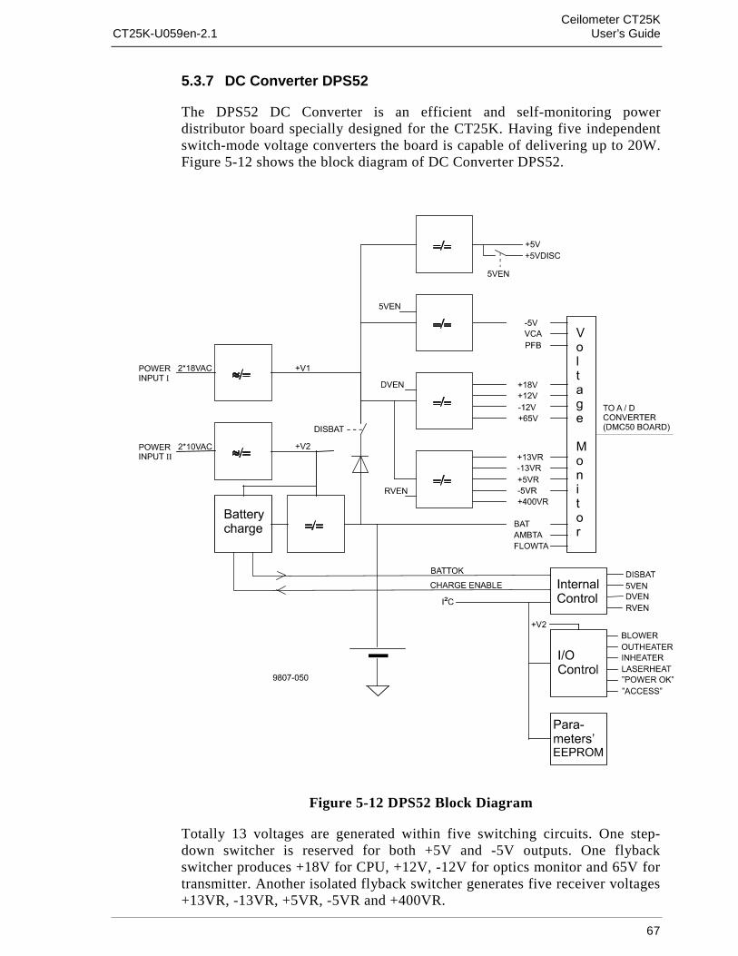
Ceilometer CT25KCT25K-U059en-2.1 User’s Guide
67
5.3.7 DC Converter DPS52
The DPS52 DC Converter is an efficient and self-monitoring powerdistributor board specially designed for the CT25K. Having five independentswitch-mode voltage converters the board is capable of delivering up to 20W.Figure 5-12 shows the block diagram of DC Converter DPS52.
Figure 5-12 DPS52 Block Diagram
Totally 13 voltages are generated within five switching circuits. One step-down switcher is reserved for both +5V and -5V outputs. One flybackswitcher produces +18V for CPU, +12V, -12V for optics monitor and 65V fortransmitter. Another isolated flyback switcher generates five receiver voltages+13VR, -13VR, +5VR, -5VR and +400VR.

Ceilometer CT25KUser’s Guide CT25K-U059en-2.1
68
All these voltages are normally supplied by two 18VAC windings. The secondsupply rectified from two 10VAC windings is reserved for internal batterycharger, heating power for transmitter and inheater and outheater controlrelays.
All voltage and two temperature channel measurements along with severalinternal and external functions are controlled by a two-wire serial I2C bus.Identification and other board specific parameters are also saved in EEPROMvia this bus.
The internal battery charger keeps the sealed lead acid battery in maximumcharge and ready for power back-up. The battery is charged in four phases orstates:
- trickle charge, while battery voltage is below normal
- bulk charge, while battery is charged with maximum current
- over charge, while battery voltage is raised over its temperaturecompensated level
- float charge, charge is complete and battery voltage is floating at thetemperature compensated level
LED functions
Two LEDs are located in the upper part of the front panel:
POWER OK LED (D2) is lit when battery circuit is connected andcharge is at least in bulk charge state and all voltages are ok.
ACCESS LED (D1) is lit every two seconds indicating a voltagechannel read cycle.
Internal switch settings
The following table describes the internal switch settings of DPS52. Fornormal operation all switches shall be OFF.
Switchposition
Switchsetting
Functions/w controlled
Switchsetting
Functionmanual
S1/1 OFF not used ON not usedS1/2 OFF digital/analog voltages ON ON digital/analog voltages OFFS1/3 OFF +/-5Vvoltages ON ON +/-5Vvoltages OFFS1/4 OFF receiver voltages OFF ON receiver voltages ON
Specifications
Input voltages:
Power Inputs: Voltage ranges:I (AC): 10 .. 22VACI (DC): 11.5 .. 30VDCII (AC): 9 .. 12VACII (DC): 9 .. 16VDC
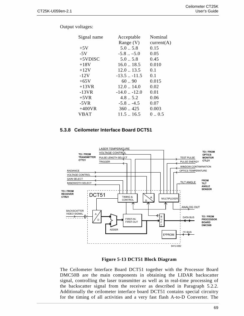
Ceilometer CT25KCT25K-U059en-2.1 User’s Guide
69
Output voltages:
Signal name AcceptableRange (V)
Nominalcurrent(A)
+5V 5.0 .. 5.8 0.15 -5V -5.8 .. –5.0 0.05 +5VDISC 5.0 .. 5.8 0.45 +18V 16.0 .. 18.5 0.010 +12V 12.0 .. 13.5 0.1 -12V -13.5 .. -11.5 0.1 +65V 60 .. 90 0.015 +13VR 12.0 .. 14.0 0.02 -13VR -14.0 .. -12.0 0.01 +5VR 4.8 .. 5.2 0.06 -5VR -5.8 .. -4.5 0.07 +400VR 360 .. 425 0.003VBAT 11.5 .. 16.5 0 .. 0.5
5.3.8 Ceilometer Interface Board DCT51
Figure 5-13 DCT51 Block Diagram
The Ceilometer Interface Board DCT51 together with the Processor BoardDMC50B are the main components in obtaining the LIDAR backscattersignal, controlling the laser transmitter as well as in real-time processing ofthe backscatter signal from the receiver as described in Paragraph 5.2.2.Additionally the ceilometer interface board DCT51 contains special circuitryfor the timing of all activities and a very fast flash A-to-D Converter. The

Ceilometer CT25KUser’s Guide CT25K-U059en-2.1
70
backscatter signal detected by the photodiode in the receiver is sampled inreal-time in this subassembly at the speed equal to that of the light beam inthe atmosphere sent from the laser transmitter. All Range Gates are sampledat each laser pulse and digitized by means of the 8-bit flash A-to-D converter.They are stored in a First-In First-Out (FIFO) memory according to the heightprofile (Figure 5-13).
For improving the Signal-to-Noise Ratio a large number of laser pulses isutilized and the samples are added to the FIFO memory in digital format. Thisway, a complete backscatter profile is then available at the end of a completemeasurement cycle. The raw values are sent via a data bus directly to theRandom Access Memory on the processor board to be algorithmicallyevaluated. A Digital-to-Analog converter outputs control signals to the lasertransmitter and receiver. The D-to-A converter is also controlled through thedata bus of the processor board.
A multiplexer contributes to the monitoring of different analog signals fromthe optics monitor, for temperature measurement of the laser and for anglemeasurement of the tilt angle. Controlled by the processor, it connects theanalog signals to the A-to-D converter of the processor board.
The timing and control circuit takes care of the triggering and length of thelaser pulse and simultaneously for the selection of receiver gain andbandwidth. The system parameters, as they are defined in the configurationand factory settings, are stored in a special EEPROM on the DCT51 board.The data transmission to and from the EEPROM is carried out through an I2CBus which is independent of the actual Data Bus.
5.3.9 Line and Power Interface Subassembly CTP241
Line AC power is connected to the Line Power and Interface SubassemblyCTP241, where it gets transformed down to low-voltage AC for supplying theDC Converter DPS52. Further, the CTP241 contains relays for controlling theInternal Heater (CT25039) and the external Window Conditioner blowermotor and airflow heater. Internal heating and window conditioning are undersoftware control via DC Converter DPS52.
WARNING
Line Power and Interface Subassembly CTP241, InternalHeaters’ Subassembly CT25039 and Window ConditionerCT2614 or CT2688 contain Line AC voltage, which maybe lethal.
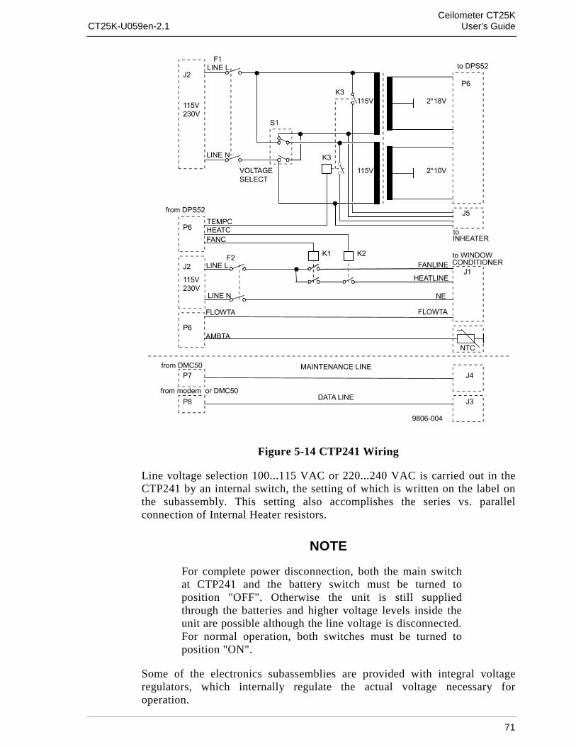
Ceilometer CT25KCT25K-U059en-2.1 User’s Guide
71
Figure 5-14 CTP241 Wiring
Line voltage selection 100...115 VAC or 220...240 VAC is carried out in theCTP241 by an internal switch, the setting of which is written on the label onthe subassembly. This setting also accomplishes the series vs. parallelconnection of Internal Heater resistors.
NOTE
For complete power disconnection, both the main switchat CTP241 and the battery switch must be turned toposition "OFF". Otherwise the unit is still suppliedthrough the batteries and higher voltage levels inside theunit are possible although the line voltage is disconnected.For normal operation, both switches must be turned toposition "ON".
Some of the electronics subassemblies are provided with integral voltageregulators, which internally regulate the actual voltage necessary foroperation.

Ceilometer CT25KUser’s Guide CT25K-U059en-2.1
72
5.3.10 Internal Heaters Subassembly CT25039
Figure 5-15 CT25039 Wiring Diagram
The Internal Heaters subassembly CT25039 increases the temperature in thearea of the optical subassembly to prevent the lens and the measurement unitwindow from becoming wet or misty. At the same time it also keeps thewhole interior above condensation temperature.
The heating subassembly consists of two power resistors with radiationelements made of aluminium. This provides a good thermal contact with thebase plate and transmission of heat to the ambient air. Thermal switchesprotect the system against overheating.
At 230 V supply voltage the resistors are connected in series by the linevoltage selection switch in the subassembly CTP241 and at 115 V supplyvoltage they are connected in parallel. A relay in the CTP241 switches poweron/off under software control via DPS52.
WARNING
The heating resistors can be very hot even after theheating has been switched off! Be cautious when workingin the vicinity of the heating!
Specifications:
Maximum power 180W (115VAC +15%, 230VAC +15%)
Max. surface temperature 130°C
Heating resistors (R1, R2):
- type HS100
- resistance 220Ω
- power 100W

Ceilometer CT25KCT25K-U059en-2.1 User’s Guide
73
Thermal switches (K1, K2):
- switch temperature 95 - 105°C
- nominal current 2.5A
- operating voltage 250VAC
5.3.11 Tilt Angle Sensor CT3675
The built-in tilt angle sensor CT3675 enables accurate cloud basemeasurements in a tilted direction. See section 2.4 for information aboutalternatives on how to use the tilt feature.
Figure 5-16 CT3675 Tilt Angle Sensor
The tilt angle sensor CT3675 contains a silicon micromechanical accelerationsensor. It measures the Earth’s gravitational force as projected on theceilometer axis. Every change in its position from vertical results in ameasurement signal dependent on the angle, which ranges from -15 to +90degrees from vertical. Internal temperature compensation and linearizationcircuits provide high stability. The output voltage of the angle sensor isdigitized through the processor board A-to-D converter and used forautomatic correction calculation, which enables accurate function in a tilteddirection. Automatic correction can be disabled with command SETMESSAGE ANGLE_COR OFF. Tilt angle can also be set manually, asdescribed in section 4.7.

Ceilometer CT25KUser’s Guide CT25K-U059en-2.1
74
5.3.12 Window Conditioner CT2614 / CT2688
Figure 5-17 Window Conditioner CT2614/CT2688

Ceilometer CT25KCT25K-U059en-2.1 User’s Guide
75
The Window Conditioner consists of a blower motor, heating element and anNTC temperature sensor inside an enclosure. The air stream from the bloweris directed across the measurement unit window for clearing it from waterdrops, condensed humidity, snow and particles.
The blower is automatically switched on when contamination or precipitationis detected on the window surface or when the atmospheric measurementindicates that a high risk of precipitation exists. The temperature sensor isused for determining whether the heater should be turned on or not. All of thisis done under software control via DPS52 and CTP241.
Because the window of the measuring unit is declined and the blower air isdirected from up to down on its surface, water drops and snow are effectivelyremoved.
CAUTION
There are two different window conditioners for the twosupply voltages 230 V and 115 V. The plug for the correctconnection cable has a marking indicating its nominalvoltage.
WARNING
The heating resistors can be very hot even after theheating has been switched off! Be cautious when handlingin the vicinity of the heating!
5.3.13 Maintenance Terminal PSION3 (Option)
The Palmtop computer PSION3 is offered as an optional light-weightmaintenance terminal. This is supplied with Series 3 Serial Link, RS232 serialinterface. PSION3 is a pocket-size terminal with high resolution display. Itincludes RAM and FLASHRAM for data storage. Two standard Mignon AAbatteries enable operation for 20 hours.
The RS232 interface RS cable has a standard 9 pin connector illustrated infigure 5-18. The RS cable is connected to Terminal cable CT3840 which isconnected to the CT25K’s maintenance line connector J4.
Figure 5-18 RS Cable

Ceilometer CT25KUser’s Guide CT25K-U059en-2.1
76
Standard port settings are the following:
Baud rate 2400
Data bits 7
Stop bits 1
Parity Even
Ignore parity Yes
For setting up PSION3 see section 2.7 Connection of maintenance terminal.
For further information about PSION3 and Series 3 Serial Link see manualsincluded in the delivery.
5.3.14 Modem DMX55 (Option)
Figure 5-19 DMX55 Block Diagram
Modem DMX55 is a universal modem primarily for fixed point-to-pointconnections. The operation mode of the modem is set at the factory.
Over a fixed point-to-point line the modem can be operated in an ANSWERor an ORIGIN mode. The modem supports different standards such as V.21,V.23 and Bell 103/202. The CT25K options are ITU-T V.21 and Bell 103.