Embed Size (px)
Citation preview
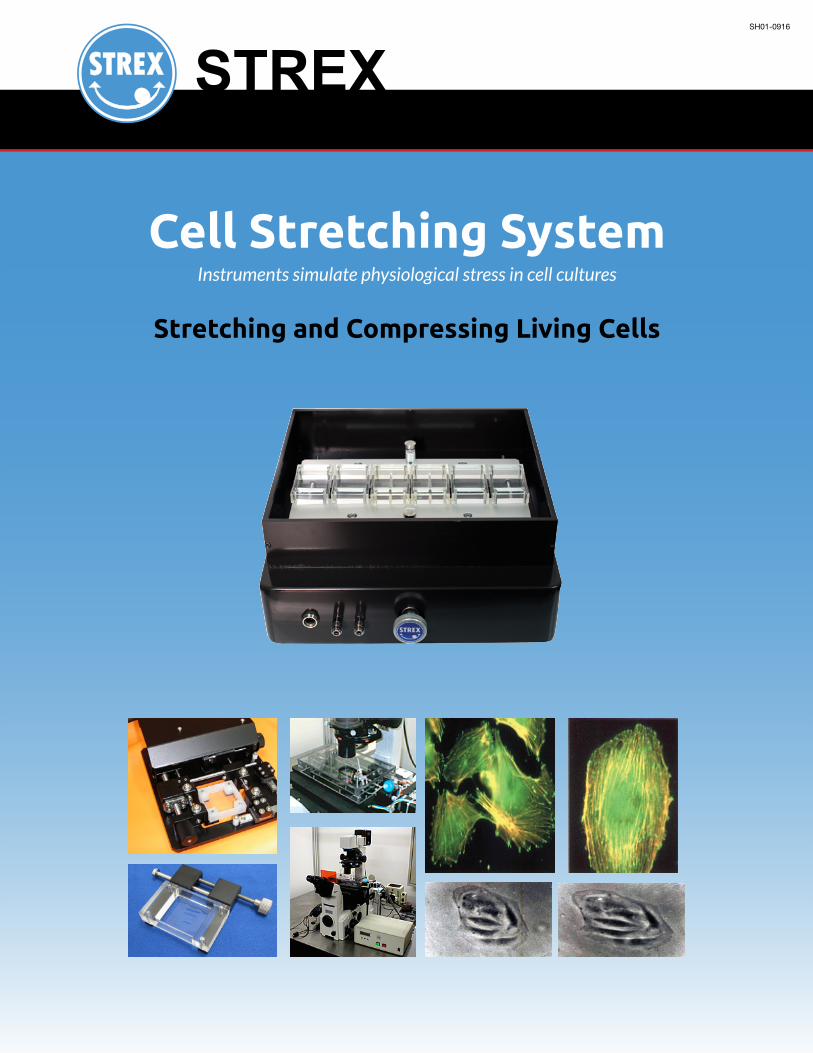
Cell Stretching System
Stretching and Compressing Living Cells
Instruments simulate physiological stress in cell cultures
SH01-0916
2
Specialized instruments simulate physiological stress in cell culturesLiving cells exist in a dynamic physiological environment, subject to a wide range of mechanical stimuli. In addition to
being stretched and compressed, cells in vivo also encounter other physical forces, including shear stress and hydrostatic
pressure. Research suggests that mechanoreceptors detect the action of these stimuli and transmit signals to the cell
interior, which in turn exert an influence on cell activity.
However, none of the stimuli from the living environment is present under standard in vitro conditions for cell culture
and analysis.
The STREX Cell Stretching System mechanically stresses cells growing in culture by stretching and compressing them,
thereby providing an environment similar to the one in which living cells exist. Thus, it differs from standard in vitro
approaches by allowing observation of the changes that the cells undergo, and the responses they manifest, in the
presence of dynamic physical forces. The system finds application for an array of cells with adhesion properties.
System Features• Uniform load: Every cell is subjected to uniform strain along the stretch axis. In the non-axial direction, the
secondary load is much weaker.
• Highreproducibility: The high-precision, high-torque stepping motor in the stretch unit enables stable motion
at a range of speeds, from extremely low velocity to high velocity. This motion stability, combined with the superior
characteristics of the silicone film chamber, produces mechanical stretching that is highly reproducible.
• WiderangeOfstretchpatterns:The system can be configured for eight different settings for the stretch
ratio — the degree of stretch desired — and eight for the repetition frequency of the stretch movement. There are 64
possible stretching patterns in all.
• Unique stretch chamber: Specially developed silicone film chamber facilitates a variety of lab analysis
techniques, including cell fixation and fluorescent imaging.
How are the stretch patterns configured?The stress load applied to cells is determined by a combination of two parameters: stretch ratio and stretch frequency.
Depending on the configuration for each parameter, cells can be stimulated continuously over time, or at cyclic intervals.
TeCHniCaL BaCkground
High-performance motor and flexible stretch chambers combine to form the ground breaking, proprietary STREX system.
StretchRatio (Degree of stretch applied)
StretchFrequency(Repetition frequency/interval of stretch)
Cyclic: Samples subjected to mechanical stretching and relaxation at fixed intervals.
Continuous:Samples subjected to sustained stretching for a predetermined period.
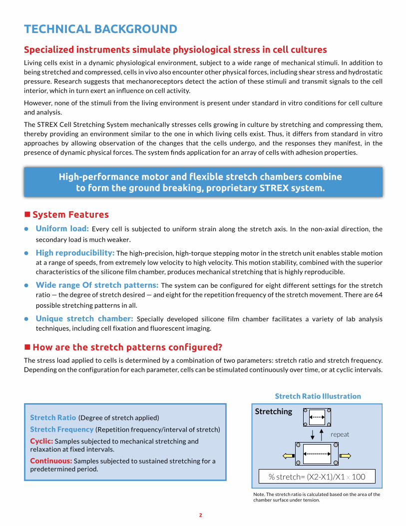
% stretch= (X2-X1)/X1 x 100
repeat
Stretching
Note. The stretch ratio is calculated based on the area of the chamber surface under tension.
StretchRatioIllustration
3
Programming by STREXThe Cell Stretching System ships programmed for eight configurations on each of the two stretch parameters, for a total
of up to 64 configurable patterns.
StretchRatio: 2,4,6,8,10,12,15,20%(20%max.)
StretchFrequency: Cyclicmode(Cyclesperminute)1,2,6,10,20,30cycles Continuousmode(Sustainedstretchtime)3sec,5sec,10sec,60sec
Cyclic StretchingTwo cycle patterns, defined by differing wave patterns (below), can be configured. One is a sustained full stretch.
The other is a gradual stretch-release cycle.
Note: Unless otherwise requested, STREX will program standard parameters appropriate for the given cell lines to be employed in the prospective research. However, custom programmed combinations (of eight non—standard configurations) are also available for users who request this option. Please contact STREX with inquiries about customized configurations.
Stre
tchi
ng R
atio
(%)
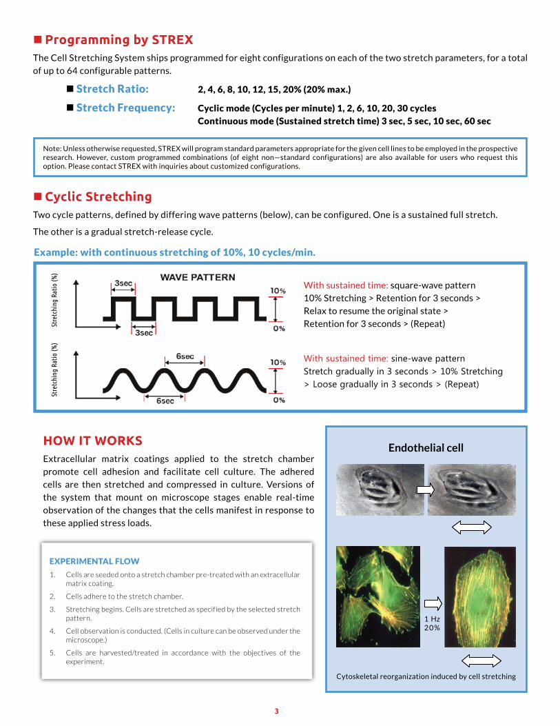
With sustained time: square-wave pattern
10% Stretching > Retention for 3 seconds >
Relax to resume the original state >
Retention for 3 seconds > (Repeat)
Example:withcontinuousstretchingof10%,10cycles/min.
With sustained time: sine-wave pattern Stretch gradually in 3 seconds > 10% Stretching > Loose gradually in 3 seconds > (Repeat)
Stre
tchi
ng R
atio
(%)
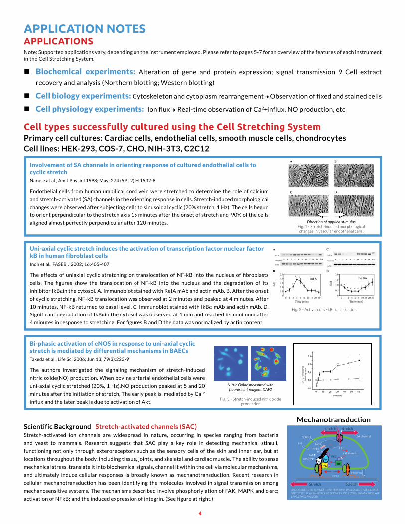
Cytoskeletal reorganization induced by cell stretching
1 Hz 2 0 %
How iT workSExtracellular matrix coatings applied to the stretch chamber
promote cell adhesion and facilitate cell culture. The adhered
cells are then stretched and compressed in culture. Versions of
the system that mount on microscope stages enable real-time
observation of the changes that the cells manifest in response to
these applied stress loads.
EXPERIMENTALFLOW
1. Cells are seeded onto a stretch chamber pre-treated with an extracellular matrix coating.
2. Cells adhere to the stretch chamber.
3. Stretching begins. Cells are stretched as specified by the selected stretch pattern.
4. Cell observation is conducted. (Cells in culture can be observed under the microscope.)
5. Cells are harvested/treated in accordance with the objectives of the experiment.
Endothelial cell
4
aPPLiCaTionSNote: Supported applications vary, depending on the instrument employed. Please refer to pages 5-7 for an overview of the features of each instrument in the Cell Stretching System.
Biochemical experiments: Alteration of gene and protein expression; signal transmission 9 Cell extract
recovery and analysis (Northern blotting; Western blotting)
Cellbiologyexperiments:Cytoskeleton and cytoplasm rearrangement → Observation of fixed and stained cells
Cellphysiologyexperiments: Ion flux → Real-time observation of Ca2+influx, NO production, etc
Cell types successfully cultured using the Cell Stretching System
aPPLiCaTion noTeS
Primary cell cultures: Cardiac cells, endothelial cells, smooth muscle cells, chondrocytesCell lines: HEK-293, COS-7, CHO, NIH-3T3, C2C12
Scientific Background Stretch-activated channels (SAC)Stretch-activated ion channels are widespread in nature, occurring in species ranging from bacteria
and yeast to mammals. Research suggests that SAC play a key role in detecting mechanical stimuli,
functioning not only through exteroreceptors such as the sensory cells of the skin and inner ear, but at
locations throughout the body, including tissue, joints, and skeletal and cardiac muscle. The ability to sense
mechanical stress, translate it into biochemical signals, channel it within the cell via molecular mechanisms,
and ultimately induce cellular responses is broadly known as mechanotransduction. Recent research in
cellular mechanotransduction has been identifying the molecules involved in signal transmission among
mechanosensitive systems. The mechanisms described involve phosphorlylation of FAK, MAPK and c-src;
activation of NFkB; and the induced expression of integrin. (See figure at right.)
PaxPK2
srcFAK
Vinc
Ca2+
calcineurin
ECM
ONCOGENE 1998, SCIENCE 1999, FEBS letter 1998/2003, F, ASEB J 2002,BBRC 2002, J Hepatol 2002, LIFE SCIENCES 2005, 2006, Nat Mat 2005, AJP1993,1998,1999,2006
SA channel
actin
P
P
P
integrins
NO/SO
NFkbNNOSIl-6
Akt�MAPK�
stretch stretch
Stretch Stretch
Mechanotransduction
InvolvementofSAchannelsinorientingresponseofculturedendothelialcellstocyclicstretchNaruse at al., Am J Physiol 1998; May; 274 (5Pt 2):H 1532-8
Endothelial cells from human umbilical cord vein were stretched to determine the role of calcium
and stretch-activated (SA) channels in the orienting response in cells. Stretch-induced morphological
changes were observed after subjecting cells to sinusoidal cyclic (20% stretch, 1 Hz). The cells begun
to orient perpendicular to the stretch axis 15 minutes after the onset of stretch and 90% of the cells
aligned almost perfectly perpendicular after 120 minutes. Direction of applied stimulusFig. 1 - Stretch-induced morphological changes in vascular endothelial cells.
Uni-axialcyclicstretchinducestheactivationoftranscriptionfactornuclearfactorkBinhumanfibroblastcellsInoh et al., FASEB J 2002; 16:405-407
The effects of uniaxial cyclic stretching on translocation of NF-kB into the nucleus of fibroblasts
cells. The figures show the translocation of NF-kB into the nucleus and the degradation of its
inhibitor IkBin the cytosol. A. Immunoblot stained with ReIA mAb and actin mAb. B. After the onset
of cyclic stretching, NF-kB translocation was observed at 2 minutes and peaked at 4 minutes. After
10 minutes, NF-kB returned to basal level. C. Immunoblot stained with IkB mAb and actin mAb. D.
Significant degradation of IkBin the cytosol was observed at 1 min and reached its minimum after
4 minutes in response to stretching. For figures B and D the data was normalized by actin content.
Fig. 2 - Activated NFkB translocation
Bi-phasicactivationofeNOSinresponsetouni-axialcyclicstretchismediatedbydifferentialmechanismsinBAECsTakeda et al., Life Sci 2006; Jun 13; 79(3):223-9
The authors investigated the signaling mechanism of stretch-induced
nitric oxide(NO) production. When bovine arterial endothelial cells were
uni-axial cyclic stretched (20%, 1 Hz),NO production peaked at 5 and 20
minutes after the initiation of stretch, The early peak is mediated by Ca+2
influx and the later peak is due to activation of Akt.
0 10 20 30 40 50 60
0.5
1.0
1.5
2.0
2.5
DA
F-2
Fluo
resc
ence
(arb
itrar
y un
its)
Time (min)
Nitric Oxide measured with fluorescent reagent DAF2
Fig. 3 - Stretch-induced nitric oxide production
5
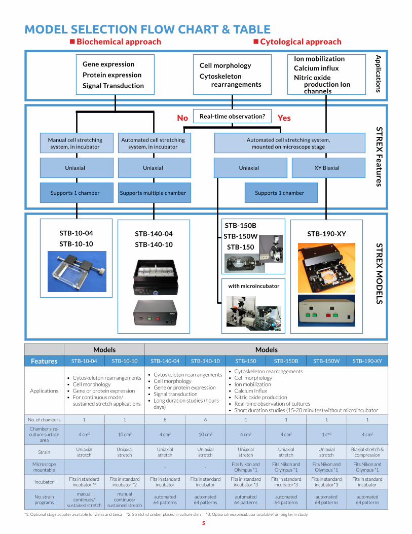
ModeL SeLeCTion FLow CHarT & TaBLe
*1: Optional stage adapter available for Zeiss and Leica *2: Stretch chamber placed in culture dish *3: Optional microincubator available for long term study
Biochemicalapproach Cytologicalapproach
YesNo
Ap
plicatio
ns
STR
EX
Features
STR
EX
MO
DE
LS
Manual cell stretching system, in incubator
Uniaxial Uniaxial
Supports 1 chamber
Automated cell stretching system, in incubator
Automated cell stretching system, mounted on microscope stage
Uniaxial XY Biaxial
Supports multiple chamber Supports 1 chamber
Real-time observation?
STB-10-04
STB-10-10
STB-140-04
STB-140-10
STB-190-XY
Models Models
Features STB-10-04 STB-10-10 STB-140-04 STB-140-10 STB-150 STB-150B STB-150W STB-190-XY
Applications
• Cytoskeleton rearrangements• Cell morphology• Gene or protein expression• For continuous mode/
sustained stretch applications
• Cytoskeleton rearrangements• Cell morphology• Gene or protein expression• Signal transduction• Long duration studies (hours-
days)
• Cytoskeleton rearrangements• Cell morphology• Ion mobilization• CalciumInflux• Nitric oxide production• Real-time observation of cultures• Short duration studies (15-20 minutes) without microincubator
No. of chambers 1 1 8 6 1 1 1 1
Chamber size-culture surface
area4 cm2 10 cm2 4 cm2 10 cm2 4 cm2 4 cm2 1 cm2 4 cm2
StrainUniaxial stretch
Uniaxial stretch
Uniaxial stretch
Uniaxial stretch
Uniaxial stretch
Uniaxial stretch
Uniaxial stretch
Biaxial stretch & compression
Microscope mountable
- -Fits Nikon and
Olympus *1Fits Nikon and
Olympus *1Fits Nikon and
Olympus *1Fits Nikon and
Olympus *1
IncubatorFits in standard
incubator *2
Fits in standard incubator *2
Fits in standard incubator
Fits in standard incubator
Fits in standard incubator *3
Fits in standard incubator*3
Fits in standard incubator*3
Fits in standard incubator
No. strain programs
manual continuos/
sustained stretch
manual continuos/
sustained stretch
automated 64 patterns
automated 64 patterns
automated 64 patterns
automated 64 patterns
automated 64 patterns
automated 64 patterns
Gene expression
Protein expression
Signal Transduction
Cell morphology
Cytoskeleton rearrangements
Ion mobilization
Calcium influx
Nitric oxide production Ion channels
STB-150B
STB-150W
STB-150
with microincubator
6
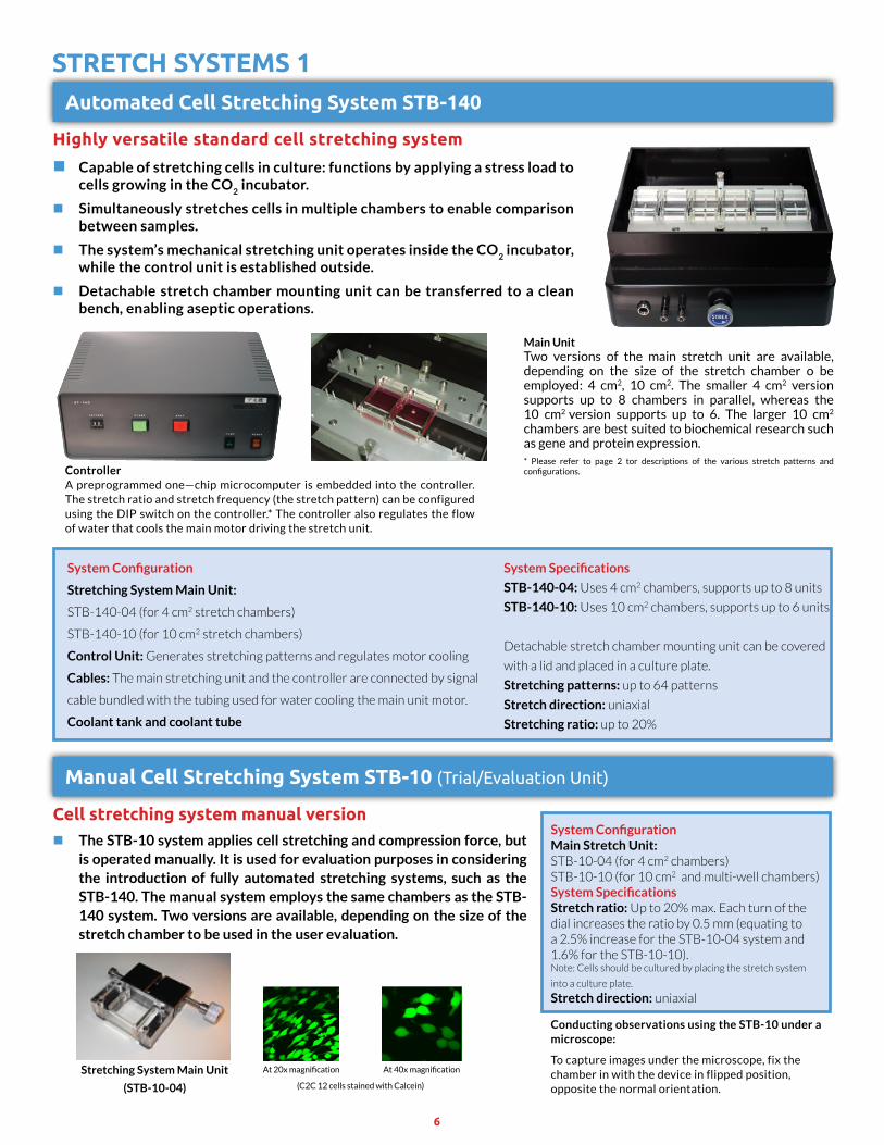
STreTCH SySTeMS 1automated Cell Stretching System STB-140
Manual Cell Stretching System STB-10 (Trial/Evaluation Unit)
Highly versatile standard cell stretching system
Capable of stretching cells in culture: functions by applying a stress load to cells growing in the CO
2 incubator.
Simultaneously stretches cells in multiple chambers to enable comparison between samples.
The system’s mechanical stretching unit operates inside the CO2 incubator,
while the control unit is established outside.
Detachable stretch chamber mounting unit can be transferred to a clean bench, enabling aseptic operations.
Cell stretching system manual version The STB-10 system applies cell stretching and compression force, but
is operated manually. It is used for evaluation purposes in considering the introduction of fully automated stretching systems, such as the STB-140. The manual system employs the same chambers as the STB-140 system. Two versions are available, depending on the size of the stretch chamber to be used in the user evaluation.
ControllerA preprogrammed one—chip microcomputer is embedded into the controller. The stretch ratio and stretch frequency (the stretch pattern) can be configured using the DIP switch on the controller.* The controller also regulates the flow of water that cools the main motor driving the stretch unit.
Main UnitTwo versions of the main stretch unit are available, depending on the size of the stretch chamber o be employed: 4 cm2, 10 cm2. The smaller 4 cm2 version supports up to 8 chambers in parallel, whereas the 10 cm2 version supports up to 6. The larger 10 cm2 chambers are best suited to biochemical research such as gene and protein expression.* Please refer to page 2 tor descriptions of the various stretch patterns and configurations.
System Configuration
Stretching System Main Unit:
STB-140-04 (for 4 cm2 stretch chambers)
STB-140-10 (for 10 cm2 stretch chambers)
Control Unit: Generates stretching patterns and regulates motor cooling
Cables: The main stretching unit and the controller are connected by signal
cable bundled with the tubing used for water cooling the main unit motor.
Coolant tank and coolant tube
System ConfigurationMain Stretch Unit:STB-10-04 (for 4 cm2 chambers)STB-10-10 (for 10 cm2 and multi-well chambers)System SpecificationsStretch ratio: Up to 20% max. Each turn of the dial increases the ratio by 0.5 mm (equating to a 2.5% increase for the STB-10-04 system and 1.6% for the STB-10-10).Note: Cells should be cultured by placing the stretch system
into a culture plate.
Stretch direction: uniaxial
System Specifications
STB-140-04: Uses 4 cm2 chambers, supports up to 8 units
STB-140-10: Uses 10 cm2 chambers, supports up to 6 units
Detachable stretch chamber mounting unit can be covered
with a lid and placed in a culture plate.
Stretching patterns: up to 64 patterns
Stretch direction: uniaxial
Stretching ratio: up to 20%
Conducting observations using the STB-10 under a microscope:
To capture images under the microscope, fix the chamber in with the device in flipped position, opposite the normal orientation.
Stretching System Main Unit
(STB-10-04)
At 20x magnification
(C2C 12 cells stained with Calcein)
At 40x magnification
7
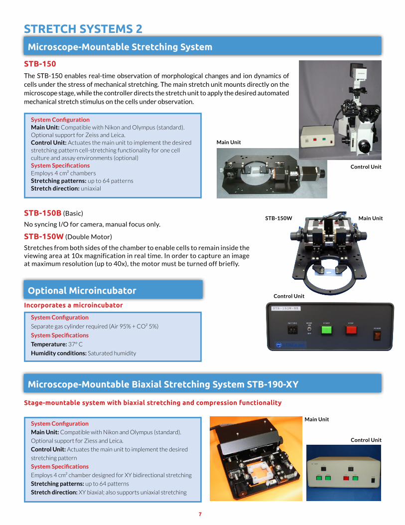
STreTCH SySTeMS 2
Microscope-Mountable Biaxial Stretching System STB-190-XY
Stage-mountable system with biaxial stretching and compression functionality
System Configuration
Main Unit: Compatible with Nikon and Olympus (standard).
Optional support for Ziess and Leica.
Control Unit: Actuates the main unit to implement the desired
stretching pattern
System Specifications
Employs 4 cm² chamber designed for XY bidirectional stretching
Stretching patterns: up to 64 patterns
Stretch direction: XY biaxial; also supports uniaxial stretching
Microscope-Mountable Stretching System
STB-150The STB-150 enables real-time observation of morphological changes and ion dynamics of cells under the stress of mechanical stretching. The main stretch unit mounts directly on the microscope stage, while the controller directs the stretch unit to apply the desired automated mechanical stretch stimulus on the cells under observation.
STB-150B (Basic)
No syncing I/O for camera, manual focus only.
STB-150w (Double Motor)
Stretches from both sides of the chamber to enable cells to remain inside the viewing area at 10x magnification in real time. In order to capture an image at maximum resolution (up to 40x), the motor must be turned off briefly.
System ConfigurationMain Unit: Compatible with Nikon and Olympus (standard).Optional support for Zeiss and Leica.Control Unit: Actuates the main unit to implement the desired stretching pattern cell-stretching functionality for one cell culture and assay environments (optional)System SpecificationsEmploys 4 cm² chambersStretching patterns: up to 64 patternsStretch direction: uniaxial
Main Unit
Main UnitSTB-150W
Main Unit
Control Unit
Control Unit
Control Unit
Optional MicroincubatorIncorporates a microincubator
System Configuration
Separate gas cylinder required (Air 95% + CO² 5%)
System Specifications
Temperature: 37° C
Humidity conditions: Saturated humidity
8
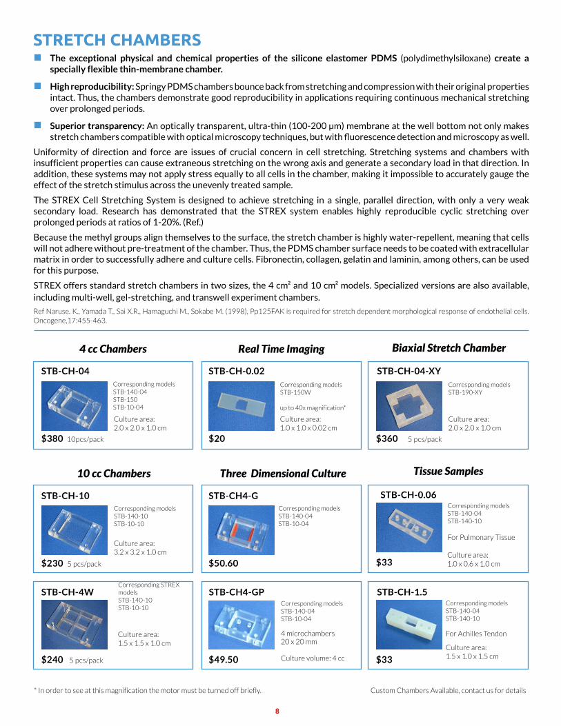
STreTCH CHaMBerS The exceptional physical and chemical properties of the silicone elastomer PDMS (polydimethylsiloxane) create a
specially flexible thin-membrane chamber.
High reproducibility: Springy PDMS chambers bounce back from stretching and compression with their original properties intact. Thus, the chambers demonstrate good reproducibility in applications requiring continuous mechanical stretching over prolonged periods.
Superior transparency: An optically transparent, ultra-thin (100-200 μm) membrane at the well bottom not only makes stretch chambers compatible with optical microscopy techniques, but with fluorescence detection and microscopy as well.
Uniformity of direction and force are issues of crucial concern in cell stretching. Stretching systems and chambers with insufficient properties can cause extraneous stretching on the wrong axis and generate a secondary load in that direction. In addition, these systems may not apply stress equally to all cells in the chamber, making it impossible to accurately gauge the effect of the stretch stimulus across the unevenly treated sample.
The STREX Cell Stretching System is designed to achieve stretching in a single, parallel direction, with only a very weak secondary load. Research has demonstrated that the STREX system enables highly reproducible cyclic stretching over prolonged periods at ratios of 1-20%. (Ref.)
Because the methyl groups align themselves to the surface, the stretch chamber is highly water-repellent, meaning that cells will not adhere without pre-treatment of the chamber. Thus, the PDMS chamber surface needs to be coated with extracellular matrix in order to successfully adhere and culture cells. Fibronectin, collagen, gelatin and laminin, among others, can be used for this purpose.
STREX offers standard stretch chambers in two sizes, the 4 cm² and 10 cm² models. Specialized versions are also available, including multi-well, gel-stretching, and transwell experiment chambers.
Ref Naruse. K., Yamada T., Sai X.R., Hamaguchi M., Sokabe M. (1998), Pp125FAK is required for stretch dependent morphological response of endothelial cells. Oncogene,17:455-463.
Culture area: 2.0 x 2.0 x 1.0 cm
Culture area: 1.0 x 0.6 x 1.0 cm
Culture area: 1.5 x 1.0 x 1.5 cm
Culture area: 1.0 x 1.0 x 0.02 cm
Culture area: 3.2 x 3.2 x 1.0 cm
Culture area: 1.5 x 1.5 x 1.0 cm
Corresponding modelsSTB-140-04 STB-150STB-10-04
Corresponding modelsSTB-140-04 STB-140-10
For Pulmonary Tissue
Corresponding modelsSTB-140-04 STB-10-04
Corresponding modelsSTB-140-04 STB-10-04
4 microchambers20 x 20 mm
Culture volume: 4 cc
Corresponding modelsSTB-140-04 STB-140-10
For Achilles Tendon
Corresponding modelsSTB-150W
up to 40x magnification*
Corresponding modelsSTB-140-10 STB-10-10
Corresponding STREX modelsSTB-140-10 STB-10-10
STB-CH-04
$380 10pcs/pack
STB-CH-1.5
$33
STB-CH4-G
$50.60
STB-CH4-GP
$49.50
STB-CH-0.02
$20
STB-CH-10
$230 5 pcs/pack
STB-CH-4W
$240 5 pcs/pack
Tissue Samples10 cc Chambers
4 cc Chambers Real Time Imaging
Custom Chambers Available, contact us for details* In order to see at this magnification the motor must be turned off briefly.
Three Dimensional Culture
Culture area: 2.0 x 2.0 x 1.0 cm
Corresponding modelsSTB-190-XY
STB-CH-04-XY
$360 5 pcs/pack
STB-CH-0.06
$33
Biaxial Stretch Chamber
9
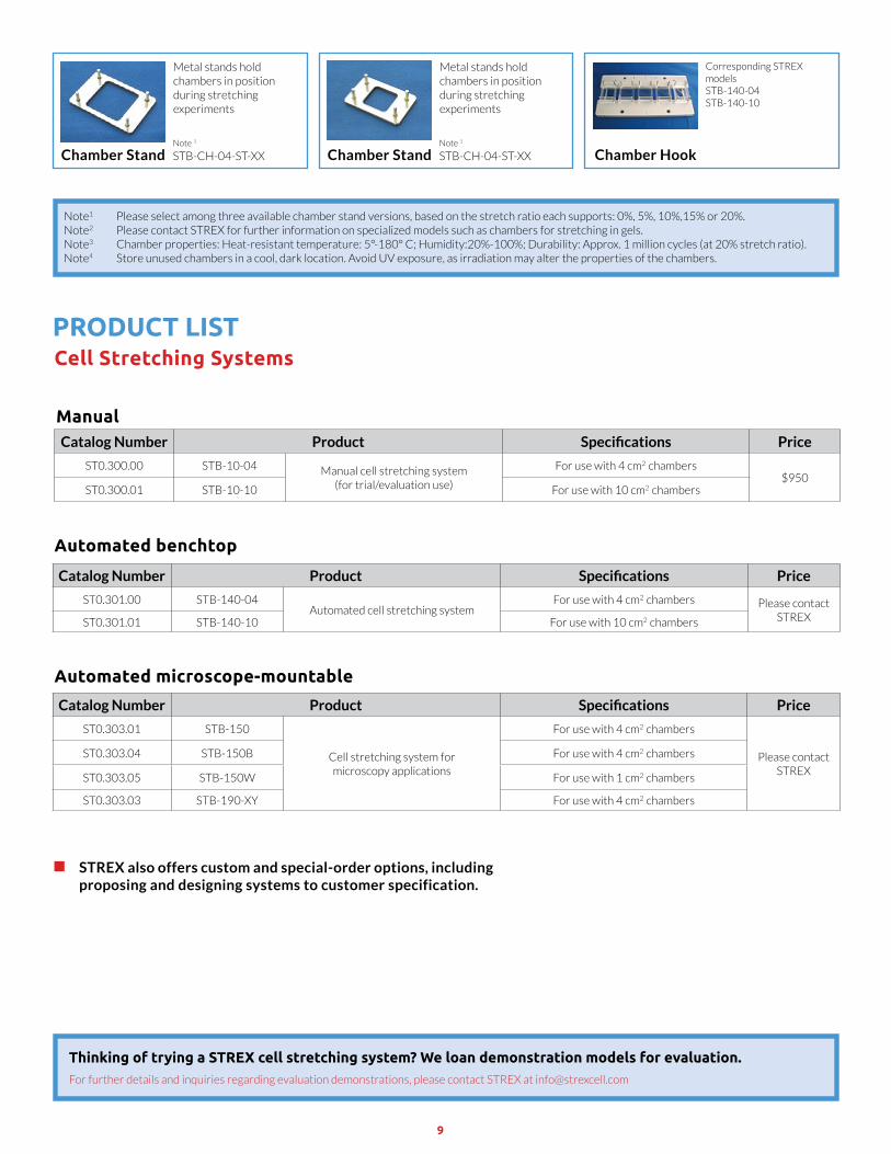
ProduCT LiSTCell Stretching Systems
Note 1
STB-CH-04-ST-XXNote 1
STB-CH-04-ST-XX
Metal stands hold chambers in position during stretching experiments
Metal stands hold chambers in position during stretching experiments
Corresponding STREX modelsSTB-140-04 STB-140-10
Chamber Stand Chamber Stand Chamber Hook
Note1 Please select among three available chamber stand versions, based on the stretch ratio each supports: 0%, 5%, 10%,15% or 20%.Note2 Please contact STREX for further information on specialized models such as chambers for stretching in gels.Note3 Chamber properties: Heat-resistant temperature: 5°-180° C; Humidity:20%-100%; Durability: Approx. 1 million cycles (at 20% stretch ratio).Note4 Store unused chambers in a cool, dark location. Avoid UV exposure, as irradiation may alter the properties of the chambers.
STREX also offers custom and special-order options, including proposing and designing systems to customer specification.
ManualCatalog Number Product Specifications Price
ST0.300.00 STB-10-04 Manual cell stretching system (for trial/evaluation use)
For use with 4 cm2 chambers$950
ST0.300.01 STB-10-10 For use with 10 cm2 chambers
Automated benchtop
Catalog Number Product Specifications Price
ST0.301.00 STB-140-04Automated cell stretching system
For use with 4 cm2 chambers Please contact STREXST0.301.01 STB-140-10 For use with 10 cm2 chambers
Automated microscope-mountable
Catalog Number Product Specifications Price
ST0.303.01 STB-150
Cell stretching system for microscopy applications
For use with 4 cm2 chambers
Please contact STREX
ST0.303.04 STB-150B For use with 4 cm2 chambers
ST0.303.05 STB-150W For use with 1 cm2 chambers
ST0.303.03 STB-190-XY For use with 4 cm2 chambers
Thinking of trying a STREX cell stretching system? We loan demonstration models for evaluation.For further details and inquiries regarding evaluation demonstrations, please contact STREX at [email protected]
10
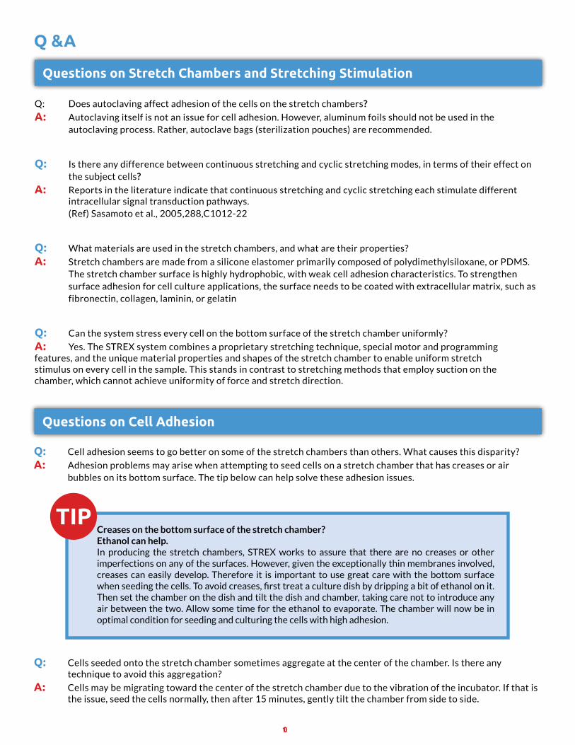
Q &a
Questions on Stretch Chambers and Stretching Stimulation
Questions on Cell adhesion
Q: Does autoclaving affect adhesion of the cells on the stretch chambers?
a: Autoclaving itself is not an issue for cell adhesion. However, aluminum foils should not be used in the autoclaving process. Rather, autoclave bags (sterilization pouches) are recommended.
Q: Is there any difference between continuous stretching and cyclic stretching modes, in terms of their effect on the subject cells?
a: Reports in the literature indicate that continuous stretching and cyclic stretching each stimulate different intracellular signal transduction pathways. (Ref) Sasamoto et al., 2005,288,C1012-22
Q: What materials are used in the stretch chambers, and what are their properties?
a: Stretch chambers are made from a silicone elastomer primarily composed of polydimethylsiloxane, or PDMS. The stretch chamber surface is highly hydrophobic, with weak cell adhesion characteristics. To strengthen surface adhesion for cell culture applications, the surface needs to be coated with extracellular matrix, such as fibronectin, collagen, laminin, or gelatin
Q: Can the system stress every cell on the bottom surface of the stretch chamber uniformly?
a: Yes. The STREX system combines a proprietary stretching technique, special motor and programming features, and the unique material properties and shapes of the stretch chamber to enable uniform stretch stimulus on every cell in the sample. This stands in contrast to stretching methods that employ suction on the chamber, which cannot achieve uniformity of force and stretch direction.
Q: Cell adhesion seems to go better on some of the stretch chambers than others. What causes this disparity?
a: Adhesion problems may arise when attempting to seed cells on a stretch chamber that has creases or air bubbles on its bottom surface. The tip below can help solve these adhesion issues.
Q: Cells seeded onto the stretch chamber sometimes aggregate at the center of the chamber. Is there any technique to avoid this aggregation?
a: Cells may be migrating toward the center of the stretch chamber due to the vibration of the incubator. If that is the issue, seed the cells normally, then after 15 minutes, gently tilt the chamber from side to side.
Creases on the bottom surface of the stretch chamber?Ethanol can help.In producing the stretch chambers, STREX works to assure that there are no creases or other imperfections on any of the surfaces. However, given the exceptionally thin membranes involved, creases can easily develop. Therefore it is important to use great care with the bottom surface when seeding the cells. To avoid creases, first treat a culture dish by dripping a bit of ethanol on it. Then set the chamber on the dish and tilt the dish and chamber, taking care not to introduce any air between the two. Allow some time for the ethanol to evaporate. The chamber will now be in optimal condition for seeding and culturing the cells with high adhesion.
11
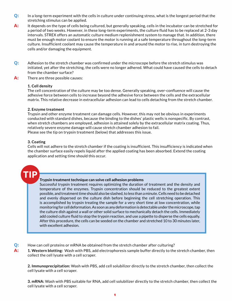
Q: In a long-term experiment with the cells in culture under continuing stress, what is the longest period that the stretching stimulus can be applied.
a: It depends on the type of cells being cultured, but generally speaking, cells in the incubator can be stretched for a period of two weeks. However, in these long-term experiments, the culture fluid has to be replaced at 2-3 day intervals. STREX offers an automatic culture medium replenishment system to manage that. In addition, there must be enough motor coolant to ensure the motor is running at a safe temperature throughout the long-term culture. Insufficient coolant may cause the temperature in and around the motor to rise, in turn destroying the cells and/or damaging the equipment.
Q: Adhesion to the stretch chamber was confirmed under the microscope before the stretch stimulus was initiated, yet after the stretching, the cells were no longer adhered. What could have caused the cells to detach from the chamber surface?
a: There are three possible causes:
1. Cell density The cell concentration of the culture may be too dense. Generally speaking, over-confluence will cause the adhesive force between cells to increase beyond the adhesive force between the cells and the extracellular matrix. This relative decrease in extracellular adhesion can lead to cells detaching from the stretch chamber.
2. Enzyme treatment Trypsin and other enzyme treatment can damage cells. However, this may not be obvious in experiments conducted with standard dishes, because the binding to the dishes’ plastic wells is nonspecific. By contrast, when stretch chambers are employed, adhesion is attained solely by the extracellular matrix coating. Thus, relatively severe enzyme damage will cause stretch chamber adhesion to fail. Please see the tip on trypsin treatment (below) that addresses this issue.
3. Coating Cells will not adhere to the stretch chamber if the coating is insufficient. This insufficiency is indicated when the chamber surface easily repels liquid after the applied coating has been absorbed. Extend the coating application and setting time should this occur.
Trypsin treatment technique can solve cell adhesion problemsSuccessful trypsin treatment requires optimizing the duration of treatment and the density and temperature of the enzymes. Trypsin concentration should be reduced to the greatest extent possible, and treatment time should also be slashed, to less than a minute. Cells need to be detached and evenly dispersed on the culture dish before beginning the cell stretching operation. This is accomplished by trypsin treating the sample for a very short time at low concentration, while monitoring for cell deformation. As soon as any deformation is detectable under the microscope, tap the culture dish against a wall or other solid surface to mechanically detach the cells. Immediately add cooled culture fluid to stop the trypsin reaction, and use a pipette to disperse the cells equally. After this procedure, the cells can be seeded on the chamber and stretched 10 to 30 minutes later, with excellent adhesion.
Q: How can cell proteins or mRNA be obtained from the stretch chamber after culturing?
a: 1. Western blotting: Wash with PBS, add electrophoresis sample buffer directly to the stretch chamber, then collect the cell lysate with a cell scraper.
2. Immunoprecipitation: Wash with PBS, add cell solubilizer directly to the stretch chamber, then collect the cell lysate with a cell scraper.
3. mRNA: Wash with PBS suitable for RNA, add cell solubilizer directly to the stretch chamber, then collect the cell lysate with a cell scraper.
12
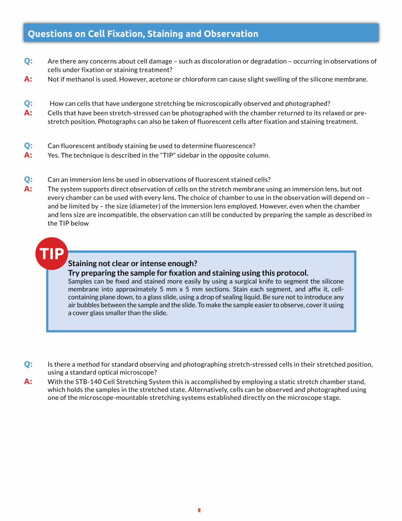
Questions on Cell Fixation, Staining and Observation
Q: Are there any concerns about cell damage – such as discoloration or degradation – occurring in observations of cells under fixation or staining treatment?
a: Not if methanol is used. However, acetone or chloroform can cause slight swelling of the silicone membrane.
Q: How can cells that have undergone stretching be microscopically observed and photographed?
a: Cells that have been stretch-stressed can be photographed with the chamber returned to its relaxed or pre- stretch position. Photographs can also be taken of fluorescent cells after fixation and staining treatment.
Q: Can fluorescent antibody staining be used to determine fluorescence?
a: Yes. The technique is described in the “TIP” sidebar in the opposite column.
Q: Can an immersion lens be used in observations of fluorescent stained cells?
a: The system supports direct observation of cells on the stretch membrane using an immersion lens, but not every chamber can be used with every lens. The choice of chamber to use in the observation will depend on – and be limited by – the size (diameter) of the immersion lens employed. However, even when the chamber and lens size are incompatible, the observation can still be conducted by preparing the sample as described in the TIP below
Q: Is there a method for standard observing and photographing stretch-stressed cells in their stretched position, using a standard optical microscope?
a: With the STB-140 Cell Stretching System this is accomplished by employing a static stretch chamber stand, which holds the samples in the stretched state. Alternatively, cells can be observed and photographed using one of the microscope-mountable stretching systems established directly on the microscope stage.
Staining not clear or intense enough? Try preparing the sample for fixation and staining using this protocol.Samples can be fixed and stained more easily by using a surgical knife to segment the silicone membrane into approximately 5 mm x 5 mm sections. Stain each segment, and affix it, cell-containing plane down, to a glass slide, using a drop of sealing liquid. Be sure not to introduce any air bubbles between the sample and the slide. To make the sample easier to observe, cover it using a cover glass smaller than the slide.
13
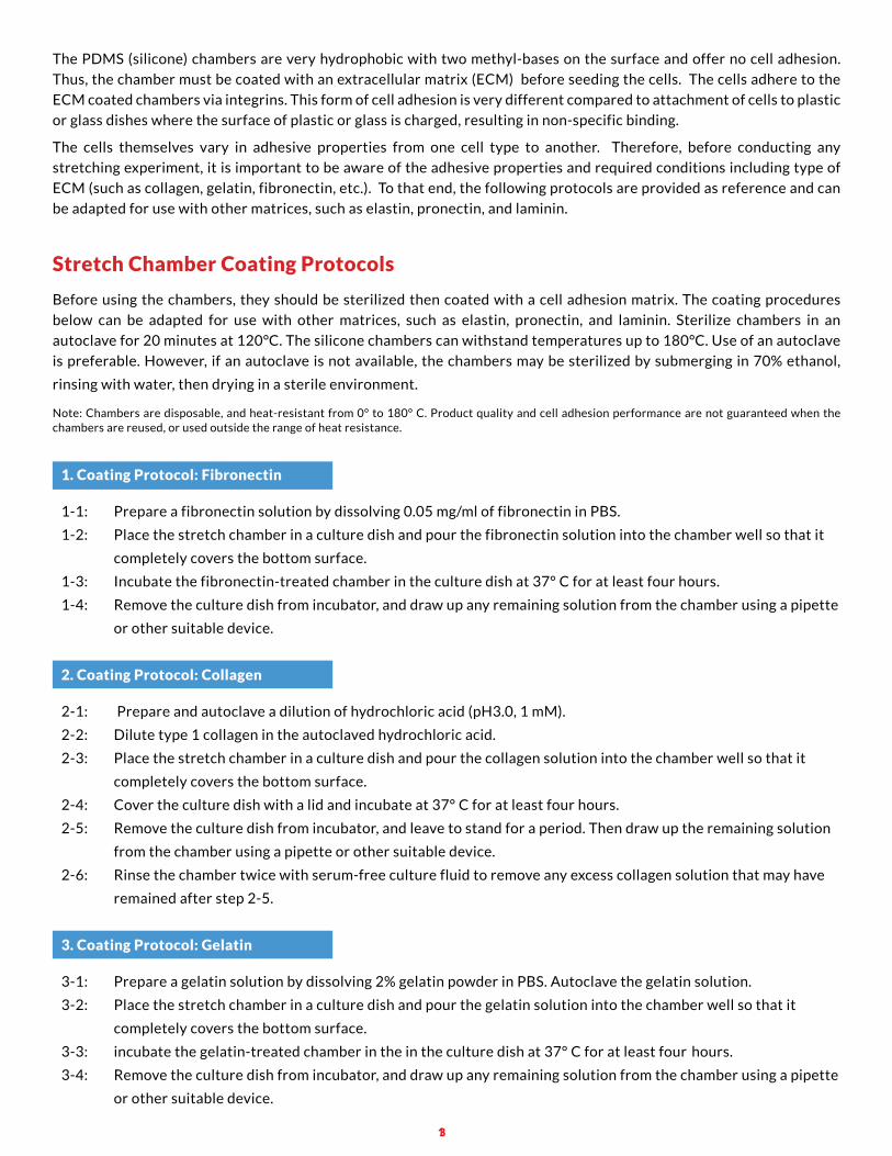
The PDMS (silicone) chambers are very hydrophobic with two methyl-bases on the surface and offer no cell adhesion.
Thus, the chamber must be coated with an extracellular matrix (ECM) before seeding the cells. The cells adhere to the
ECM coated chambers via integrins. This form of cell adhesion is very different compared to attachment of cells to plastic
or glass dishes where the surface of plastic or glass is charged, resulting in non-specific binding.
The cells themselves vary in adhesive properties from one cell type to another. Therefore, before conducting any
stretching experiment, it is important to be aware of the adhesive properties and required conditions including type of
ECM (such as collagen, gelatin, fibronectin, etc.). To that end, the following protocols are provided as reference and can
be adapted for use with other matrices, such as elastin, pronectin, and laminin.
1.CoatingProtocol:Fibronectin
1-1: Prepare a fibronectin solution by dissolving 0.05 mg/ml of fibronectin in PBS.
1-2: Place the stretch chamber in a culture dish and pour the fibronectin solution into the chamber well so that it
completely covers the bottom surface.
1-3: Incubate the fibronectin-treated chamber in the culture dish at 37° C for at least four hours.
1-4: Remove the culture dish from incubator, and draw up any remaining solution from the chamber using a pipette
or other suitable device.
2.CoatingProtocol:Collagen
2-1: Prepare and autoclave a dilution of hydrochloric acid (pH3.0, 1 mM).
2-2: Dilute type 1 collagen in the autoclaved hydrochloric acid.
2-3: Place the stretch chamber in a culture dish and pour the collagen solution into the chamber well so that it
completely covers the bottom surface.
2-4: Cover the culture dish with a lid and incubate at 37° C for at least four hours.
2-5: Remove the culture dish from incubator, and leave to stand for a period. Then draw up the remaining solution
from the chamber using a pipette or other suitable device.
2-6: Rinse the chamber twice with serum-free culture fluid to remove any excess collagen solution that may have
remained after step 2-5.
3.CoatingProtocol:Gelatin
3-1: Prepare a gelatin solution by dissolving 2% gelatin powder in PBS. Autoclave the gelatin solution.
3-2: Place the stretch chamber in a culture dish and pour the gelatin solution into the chamber well so that it
completely covers the bottom surface.
3-3: incubate the gelatin-treated chamber in the in the culture dish at 37° C for at least four hours.
3-4: Remove the culture dish from incubator, and draw up any remaining solution from the chamber using a pipette
or other suitable device.
StretchChamberCoatingProtocols
Before using the chambers, they should be sterilized then coated with a cell adhesion matrix. The coating procedures
below can be adapted for use with other matrices, such as elastin, pronectin, and laminin. Sterilize chambers in an
autoclave for 20 minutes at 120°C. The silicone chambers can withstand temperatures up to 180°C. Use of an autoclave
is preferable. However, if an autoclave is not available, the chambers may be sterilized by submerging in 70% ethanol,
rinsing with water, then drying in a sterile environment.
Note: Chambers are disposable, and heat-resistant from 0° to 180° C. Product quality and cell adhesion performance are not guaranteed when the chambers are reused, or used outside the range of heat resistance.
14
Strex USA Toll Free: (866) 844-4374 [email protected] 7098 Miratech Drive, Suite 100, San Diego CA 92121
RESEARCH CITIng THE USE OF THE STREX CEll STRETCHIng SYSTEMUniaxial and static stretch dependent-signal transduction:
Amma H, Naruse K, Ishiguro N, Sokabe M. (2005) Involvement of reactive oxygen species in cyclic stretch-induced NF-kappaB activation in human fibroblast cells. Br J Pharmacol, 45:364-373.
Furuya, K., Sokabe, M., Furuya, S. (2005) Characteristics of subepithelial fibroblasts as a mechano-sensor in the intestine: cell-shape-dependent ATP release and P2Y1 signaling. J Cell Sci,118:3289-3304.
Inoh H, Ishiguro N, Sawazaki S, Amma H, Miyazu M, Iwata H, Sokabe M, Naruse K. (2002) Uni-axial cyclic stretch induces the activation of transcription factor nuclear factor kappa in human fibroblast cells. FASEB J,6:405-407
Kada,K., Yasui, K., Naruse K., Kamiya, K., Kodama, I., Toyama, J. (1999) Orientation change of cardiocytes induced by cyclic stretch stimulation: time dependency and involvement of protein kinases. J Mol Cell Cardiol, 31:247-259.
Kato, T., Ishiguro, N., Iwata, H., Kojima, T., Ito, T., Naruse, K. (1998) Up-regulation of COX2 expression by uni-axial cyclic stretch in human lung fibroblast cells. Biochem Biophys Res Comm,244:615-619
Matsuda, T., Fujio, Y., Nariai, T., Ito, T., Yamane, M., Takatani, T., Takahashi, K., Azuma, J. (2006) N-cadherin signals through Rac1 determine the localization of connexin 43 in cardiac myocytes. J Mol Cell Cardiol, 40:495-502
Naruse, K., Yamada, T., Sai, X.R., Hamaguchi, M., Sokabe, M. (1998) Pp125FAK is required for stretch dependent morphological response of endothelial cells. Oncogene,17:455-463.
Sai, X., Naruse, K., Sokabe, M. (1999) Activation of pp60src is critical for stretch-induced orienting response in fibroblasts. J Cell Sci,112:1365-1373
Sasamoto A, Nagino M, Kobayashi S, Naruse K, Nimura Y, Sokabe M. (2005) Mechanotransduction by integrin is essential for IL-6 secretion from endothelial cells in response to uniaxial continuous stretch. Am J Physiol Cell Physiol, 288:C1012-22
Takeda H, Komori K, Nishikimi N, Nimura Y, Sokabe M, Naruse K. (2006) Bi-phasic activation of eNOS in response to uni-axial cyclic stretch is mediated by differential mechanisms in BAECs. Life Sci, 79:233-239
Wang JG, Miyazu M, Xiang P, Li SN, Sokabe M, Naruse K. (2005) Stretch-induced cell proliferation is mediated by FAK-MAPK pathway. Life Sci,76:2817-2825
Cell adhesion:
Matsuda, T., Takahashi, K., Nariai, T., Ito, T., Takatani, T., Fujio, Y., Azuma. J. (2005) N-cadherin-mediated cell adhesion determines the plasticity for cell alignment in response to mechanical stretch in cultured cardiomyocytes. Biochem Biophy Res Comm,326:228-232
Sa channels:
Aikawa, K., Nishikimi, N., Sakurai, T., Nimura, Y., Sokabe, M., Naruse, K. (2001) SA channel mediates superoxide production in HUVECs. Life Sci,69:1717-24.
Danciu TE, Adam RM, Naruse K, Freeman MR, Hauschka PV. (2003) Calcium regulates the PI3K-Akt pathway in stretched osteoblasts. FEBS Lett,536:193-197
Ito S, Kume H, Oguma T, Ito Y, Kondo M, Shimokata K, Suki B, Naruse K. (2006) Roles of stretch-activated cation channel and Rho-kinase in the spontaneous contraction of airway smooth muscle. Eur J Pharmacol,552:135-1421
Naruse, K., Yamada, T., Sokabe, M. (1998) Involvement of SA channels in orienting response of culture endothelial cells in cyclic stretch. Am J Physiol,274:H1532-H1538
nano-materials:
Zhu, X., Mills, K.L., Peters, P.R., Bahng, J.H., Liu, E.H., Shim, J., Naruse, K., Csete, M.E., Thouless, M.D., Yokoyama, S. (2005) Fabrication of reconfigurable protein matrices by cracking. Nat Mater, 4:403-406
Mechanotransduction: references and review articles
Kanzaki, M., Nagasawa, M., Kojima, I., Sato, C., Naruse, K., Sokabe, M., Iida, H. (1999) Molecular Identification of a Eukaryotic, Stretch-Activated Nonselective Cation Channel. Science,285:882-886
Qi, Z., Chi, S., Su, X., Naruse, K., Sokabe, M. (2005) Activation of a mechanosensitive BK channel by membrane stress created with amphipaths. Mol Membr Biol,22:519-527
Naruse, K. (2004) Soft lithography and mechanobiology. Vascular Biology & Medicine, 5:237-244
Naruse, K. (2006) Mechanotransduction research driving soft lithography. Protein, Nucleic Acid and Enzyme, 51:705-714