Embed Size (px)
Citation preview

CellPipe™ 20 SeriesUser’s Guide
Part Number: 7820-0766-003July 2001

Copyright © 2001 Lucent Technologies Inc. All rights reserved.
This material is protected by the copyright laws of the United States and other countries. It may not be reproduced, distributed, or altered in anyfashion by any entity (either internal or external to Lucent Technologies), except in accordance with applicable agreements, contracts, or licensing,without the express written consent of Lucent Technologies. For permission to reproduce or distribute, please email your request [email protected].
Notice
Every effort was made to ensure that the information in this document was complete and accurate at the time of printing, but information is subjectto change.
European Community (EC) RTTE compliance
Hereby, Lucent Technologies, declares that the equipment documented in this publication is in compliance with the essential requirementsand other relevant provisions of the Radio and Telecommunications Technical Equipment (RTTE) Directive 1999/5/EC.
To view the official Declaration of Conformity certificate for this equipment, according to EN 45014, access the Lucent INS online documentationlibrary at http://www.lucent.com/ins/doclibrary.html and click the CE symbol.
Safety, compliance, and warranty information
Before handling any Lucent Access Networks hardware product, read the Edge Access Safety and Compliance Guide included in your productpackage. See that guide also to determine how products comply with the electromagnetic interference (EMI) and network compatibility requirementsof your country. See the warranty card included in your product package for the limited warranty that Lucent Technologies provides for its products.
Security statement
In rare instances, unauthorized individuals make connections to the telecommunications network through the use of access features.
Trademarks
Lucent, the Lucent logo, and all Lucent brand and product names are trademarks or registered trademarks of Lucent Technologies Inc. Other brandand product names are trademarks of their respective holders.
Copyrights for third-party software included in Lucent Access Networks software products
C++ Standard Template Library software copyright© 1994 Hewlett-Packard Company and copyright© 1997 Silicon Graphics. Permission to use,copy, modify, distribute, and sell this software and its documentation for any purpose is hereby granted without fee, provided that the abovecopyright notice appear in all copies and that both that copyright notice and this permission notice appear in supporting documentation. NeitherHewlett-Packard nor Silicon Graphics makes any representations about the suitability of this software for any purpose. It is provided “as is” withoutexpress or implied warranty.
Berkeley Software Distribution (BSD) UNIX software copyright© 1982, 1986, 1988, 1993 The Regents of California. All rights reserved.Redistribution and use in source and binary forms, with or without modification, are permitted provided that the following conditions are met: 1.Redistributions of source code must retain the above copyright notice, this list of conditions, and the following disclaimer. 2. Redistributions inbinary form must reproduce the above copyright notice, this list of conditions, and the following disclaimer in the documentation and/or othermaterials provided with the distribution. 3. All advertising materials mentioning features or use of this software must display the followingacknowledgement: This product includes software developed by the University of California, Berkeley, and its contributors. 4. Neither the name ofthe University nor the names of its contributors may be used to endorse or promote products derived from this software without specific prior writtenpermission.
THIS SOFTWARE IS PROVIDED BY THE REGENTS AND CONTRIBUTORS “AS IS” AND ANY EXPRESS OR IMPLIED WARRANTIES,INCLUDING, BUT NOT LIMITED TO, THE IMPLIED WARRANTIES OF MERCHANTABILITY AND FITNESS FOR A PARTICULARPURPOSE ARE DISCLAIMED. IN NO EVENT SHALL THE REGENTS OR CONTRIBUTORS BE LIABLE FOR ANY DIRECT, INDIRECT,INCIDENTAL, SPECIAL, EXEMPLARY, OR CONSEQUENTIAL DAMAGES (INCLUDING, BUT NOT LIMITED TO, PROCUREMENT OFSUBSTITUTE GOODS OR SERVICES; LOSS OF USE, DATA OR PROFITS; OR BUSINESS INTERRUPTION) HOWEVER CAUSED ANDON ANY THEORY OF LIABILITY, WHETHER IN CONTRACT, STRICT LIABILITY, OR TORT (INCLUDING NEGLIGENCE OROTHERWISE) ARISING IN ANY WAY OUT OF THE USE OF THIS SOFTWARE, EVEN IF ADVISED OF THE POSSIBILITY OF SUCHDAMAGE.
Feedback
Lucent Technologies appreciates customer comments about this manual. Please send them to [email protected].
Lucent Technologies

Customer Service
Customer ServiceVisit the eSight™ Service Center at http://www.esight.com for a variety of technical support and information. The center is open 24 hours a day, seven days a week.
Finding information and software
The eSight Service Center at http://www.esight.com provides technical information, product information, electronic versions of product manuals, software upgrades, release notes, addenda, and descriptions of available services. Log in and select a service.
Ordering information
You can order computer-based training online at http://www.lucent.com/ins/bookstore.
Obtaining technical assistance
The eSight™ Service Center provides access to technical support. You can also obtain technical assistance through email or by telephone.
If you need to contact Lucent Technologies for assistance, make sure that you have the following information available:
• Active contract number, product name, model, and serial number
• Software version
• Software and hardware options
• If supplied by your carrier, service profile identifiers (SPIDs) associated with your line
• Your local telephone company’s switch type and operating mode, such as AT&T 5ESS Custom or Northern Telecom National ISDN-1
• Whether you are routing or bridging with your Lucent product
CellPipe™ 20 Series User’s Guide iii

Important safety instructions
• Type of computer you are using
• Description of the problem
Obtaining assistance through email or the Internet
If your service agreement allows, you can communicate directly with a technical engineer through Email Technical Support or eSight Live chat. Select one of these sites when you log in to http://www.esight.com.
Calling the technical assistance center (TAC)
If you cannot find an answer through the tools and information on eSight or if you have a very urgent need, contact TAC. Access the eSight Service Center at http://www.esight.com and click Contact Us below the Lucent Technologies logo for a list of telephone numbers inside and outside the United States.
You can alternatively call (800) 272-3634 for a menu of Lucent services, or call (510) 769-6001 for an operator. If you do not have an active services agreement or contract, you will be charged for time and materials.
Important safety instructions
A. General requirements1 Read and follow all warning notices and instructions marked on the product or
included in the manual.
2 There are no operator serviceable parts within the unit. Refer all servicing to trained service personnel.
3 Product installation should be performed by trained service personnel only.
4 Install only in restricted-access areas in accordance with UL1950, C22.2 No. 950, and IEC60950
5 The maximum recommended operating ambient is 122° F (50° C). Allow sufficient air circulation or space between units when installed in a closed or multiple-rack assembly.
6 Slots and openings in the cabinet are provided for ventilation. To ensure reliable operation of the product and to protect it from overheating, these slots and
iv CellPipe™ 20 Series User’s Guide

Important safety instructions
openings must not be blocked or covered. Installation without sufficient airflow can be unsafe.
7 Equipment mounted in a rack should be distributed to prevent a possible hazardous condition due to uneven loading. The rack should safely support the combined weight of all equipment. This product weighs 2 lb.
8 The power source has to be adequately rated to assure safe operation of the equipment. The building installation and/or power source must provide overload protection.
9 Protective earth (PE) connection is essential to ensure safe operation before connecting to the power supply and telecommunication network. Do not defeat the purpose of the grounding-type plug by modifying the plug or using an adapter. Use an outlet tester or a voltmeter to check the ac receptacle for the presence of earth ground. If the receptacle is not properly grounded, the installation must not proceed until a qualified electrician has corrected the problem.
If the power supply is fed from a power source with no protective-earthing path (such as in certain Nordic countries), connect an earth-grounded copper wire to
the dedicated wiring terminal marked with (PE symbol) on the chassis. The minimum size of the wire for a CellPipe unit with rated input current not
exceeding 6A is AWG 18 and cross-sectional area 0.75 mm2.
Models with ac power inputs are intended for use with a single-phase three-wire power cord (which includes earthing conductor).
For models with dc power inputs, the protective earth connection must be established by using the dedicated earthing terminal marked with the PE symbol or, if provided, the earthing pin of the input terminal block.
10 Models with dc power inputs must be connected to a -48V dc supply source that is electrically isolated from the ac source in accordance with UL1950, C22.2 No. 950, and IEC60950.
11 For products installed in Nordic countries (except Central Office equipment), a type B plug or permanent connection must be used for connections to the main power supply.
12 Before installing wires to the dc power terminal block, verify that these wires are not connected to any power source. Installing live wires (that is, wires connected to a power source) is hazardous.
13 Do not allow anything to rest on the power cord, and do not locate the product where people will walk on the power cord.
CellPipe™ 20 Series User’s Guide v

Important safety instructions
14 Do not attempt to service this product yourself. Opening or removing covers can expose you to dangerous high voltage points or other risks. Refer all servicing to qualified service personnel.
15 General purpose cables are provided with this product. Special cables, which might be required by the regulatory inspection authority for the installation site, are the responsibility of the customer.
16 When installed in the final configuration, the product must comply with the applicable safety standards and regulatory requirements of the country in which it is installed. If necessary, consult with the appropriate regulatory agencies and inspection authorities to ensure compliance.
17 A rare phenomenon can create a voltage potential between the earth grounds of two or more buildings. If products installed in separate buildings are interconnected, the voltage potential might cause a hazardous condition. Consult a qualified electrical consultant to determine whether or not this phenomenon exists.
In addition, if the equipment is to be used with telecommunications circuits, take the following precautions:
• Never install telephone wiring during a lightning storm.
• Never install telephone jacks in wet locations unless the jack is specifically designed for wet locations.
• Never touch uninsulated telephone wires or terminals unless the telephone line has been disconnected at the network interface.
• Use caution when installing or modifying telephone lines.
• Avoid using equipment connected to telephone lines (other than a cordless telephone) during an electrical storm. There is a remote risk of electric shock from lightning.
• Do not use a telephone or other equipment connected to telephone lines to report a gas leak in the vicinity of the leak.
! Warning: To reduce the risk of fire, communication cable conductors must be 26 AWG (0.13 mm2) or larger.
!Avertissement: A fin de réduire les risques d'incendie, les fils conducteurs du câble de communication doivent être d'un calibre minimum de 26 AWG (American Wire Gauge), c'est-à-dire d'un minimum de 0,13 mm².
vi CellPipe™ 20 Series User’s Guide

Important safety instructions
!Warnung: Um Feuer-Risiko zu reduzieren, müsssen die Querschnitte der Kommunikationskabel-Leiter 0,13 mm² oder größer sein.
B. Special requirements
1 Lithium batteries:
! Warning: The battery can explode if incorrectly replaced. Replace the battery only with the same or equivalent type recommended by the manufacturer. Dispose of used batteries according to the manufacturer’s instructions.
!Avertissement: Il y a danger d'explosion si la batterie n'est pas remplacée correctement. Remplacer uniquement avec une batterie du même type ou d'un type recommandé par le fabricant. Mettre au rebut les batteries usagées conformément aux instructions du fabricant.
!Warnung: Die Batterie kann eventuell explodieren, wenn sie nicht ordnungsgemäß ausgetauscht wird. Ersetzen Sie die Batterie nur mit einer Batterie des gleichen oder eines ähnlichen vom Hersteller empfohlenen Typs. Entsorgen Sie gebrauchte Batterien gemäß den Anweisungen des Herstellers.
2 Main Disconnect (no power switch):
! Caution: The power supply cord is used as the main disconnect device. Make sure that the outlet socket is located/installed near the equipment and is easily accessible.
! Attention: Le cordon d'alimentation est utilisé comme interrupteur général. La prise de courant doit être située ou installée à proximité du matériel et être facile d'accès.
! Vorsicht: Zur sicheren Trennung des Gerätes vom Netz muß der Netzstecker gezogen werden. Stellen Sie sicher, daß sich die Steckdose in der Nähe des Gerätes befindet und leicht zugänglich ist.
CellPipe™ 20 Series User’s Guide vii


Contents
Customer Service ..................................................................................................... iiiFinding information and software .................................................................... iiiOrdering information ........................................................................................ iiiObtaining technical assistance ......................................................................... iii
Important safety instructions .................................................................................... iv
Introduction .......................................................................... 1-1
About this guide .................................................................................................... 1-1What is the CellPipe 20 Series Product Family? ................................................... 1-2Lucent TURN-UP .................................................................................................. 1-3CellPipe 20 Series management ............................................................................ 1-3
Setup ..................................................................................... 2-1
Verifying package contents ................................................................................... 2-1Items you need for installation .............................................................................. 2-2Connecting CellPipe 20 Series products ............................................................... 2-2Checking status lights ............................................................................................ 2-4Console setup ......................................................................................................... 2-4
Command-Line Interface ..................................................... 3-1
Syntax of command-line interface ......................................................................... 3-1Using the commands ............................................................................................. 3-2
Viewing the main menu ................................................................................. 3-2Displaying information about a command ..................................................... 3-2Returning to the main menu ........................................................................... 3-3
CellPipe™ 20 Series User’s Guide ix

Contents
Displaying second-level commands ............................................................... 3-3Saving configurations ..................................................................................... 3-3
Bridging commands ............................................................................................... 3-3Routing commands ................................................................................................ 3-6
Configuring a 20 Series CellPipe ...................................... 4-1
Auto-provisioning .................................................................................................. 4-1Configuring WAN interface .................................................................................. 4-2
SDSL commands and configurations ............................................................. 4-2ADSL commands and configurations ............................................................ 4-4
Configuring LAN interface .................................................................................... 4-7Configuring LAN interface in bridging mode ................................................ 4-7Configuring LAN interface in routing mode .................................................. 4-8
Configuring the manage command ........................................................................ 4-9Configuring the mode command ........................................................................... 4-9Configuring the quick command ......................................................................... 4-10
The quick command in bridging mode ......................................................... 4-10The quick command in routing mode ........................................................... 4-10
Configuring the r1483 command ......................................................................... 4-11The r1483 command in bridging mode ........................................................ 4-11The r1483 command in routing mode .......................................................... 4-12
Configuring the dnsrelay command ..................................................................... 4-13Configuring the ipoa command ........................................................................... 4-13Configuring the pppoa command ........................................................................ 4-14Configuring the pat command ............................................................................. 4-15
Upgrading System Software .............................................. 5-1
Preparing to upgrade .............................................................................................. 5-1Obtaining software ................................................................................................. 5-1Upgrading software ............................................................................................... 5-2
Warranties and FCC Regulations ...................................... A-1
Product warranty ................................................................................................... A-1Warranty repair .............................................................................................. A-2Out-of warranty repair ................................................................................... A-2
FCC Part 15 Notice ............................................................................................... A-2IC CS-03 Notice ................................................................................................... A-3
x CellPipe™ 20 Series User’s Guide

Contents
Warranties and FCC Regulations ...................................... B-1
Product warranty ................................................................................................... B-1Warranty repair .............................................................................................. B-2Out-of warranty repair .................................................................................... B-2
FCC Part 15 Notice ............................................................................................... B-2IC CS-03 Notice .................................................................................................... B-3
CellPipe™ 20 Series User’s Guide xi


CellPipe™ 20 Series User’s Guide
1
IntroductionAbout this guideThis document is a combined user’s guide for the CellPipe™ 20 Series Product Family. The products currently addressed by this guide include the following:
• CellPipe 20A-GX, supporting software version 1.17ML
• CellPipe 20S, supporting software version 2.31ML
The contents of this guide include basic information about the aforementioned units, such as standard features, setup instructions, and information on how to configure and administer the units. This guide is written primarily to provide information for network administrators responsible for configuring and administering the units and secondarily to acquaint users with the functionalities of the units.
For additional support, you can also visit the eSight™ Service Center at http://www.esight.com to download software upgrades, release notes, and manuals pertaining to this product family.
About this guide . . . . . . . . . . . . . . . . . . . . . . . . . . . . . . . . . . . . . . . . . . . . . . . . . . 1-1
What is the CellPipe 20 Series Product Family? . . . . . . . . . . . . . . . . . . . . . . . . . 1-2
Lucent TURN-UP. . . . . . . . . . . . . . . . . . . . . . . . . . . . . . . . . . . . . . . . . . . . . . . . . 1-3
CellPipe 20 Series management . . . . . . . . . . . . . . . . . . . . . . . . . . . . . . . . . . . . . . 1-3
1-1

IntroductionWhat is the CellPipe 20 Series Product Family?
What is the CellPipe 20 Series Product Family?The current CellPipe 20 Series Product Family consists of two groups of products—symmetrical digital subscriber line (SDSL) and asymmetrical digital subscriber line (ADSL)—for Point-to-Point Protocol (PPP) or Frame Relay over asynchronous transfer mode (ATM).
Units that support a SDSL WAN interface operate with symmetrical transmission and receive rates in the range of 144Kbps to 2.32Mbps. Units that support an ADSL WAN interface operate with asymmetrical transmission and receive downstream rates of 64Kbps to 8.1Mbps and upstream rates of 64Kbps to 800Kbps See Table 1-1 for a summary of the features for each product.
Table 1-1. CellPipe 20 Series products
CellPipe units Description
CellPipe 20A-GX Support for:
• IP routing and bridging, PPP support
• Asymmetrical transmission with downstream rates of 64Kbps to 8Mbps and upstream rates of 64Kbps to 1Mbps
• One 10BaseT Ethernet port
• Eight PVCs in bridging mode
• Five PVCs in routing mode
CellPipe 20S Support for:
• IP routing and bridging, PPP support
• Symmetrical transmission rates in the range of 144Kbps to 2.32Mbps
• Integrated four-port 10BaseT Ethernet hub
• Eight PVCs in bridging mode
• Five PVCs in routing mode
1-2 CellPipe™ 20 Series User’s Guide

IntroductionLucent TURN-UP
Lucent TURN-UPThe CellPipe 20 Series Product Family supports the Lucent TURN-UP™ automated CPE provisioning system. TURN-Up is enabled when a user powers up his unit and allows service providers to quickly and efficiently distribute and provision CPE gear without the use of truck-rolls. Furthermore, TURN-UP stores configuration information on a central server, making configuration management efficient and easy.
! Caution: If you attempt to manually configure the unit, TURN-UP will be disabled. To re-enable TURN-UP, you need to select the default command and reinstall the factory default configuration.
CellPipe 20 Series managementCellPipe 20 Series units can be managed via three different connections:
• Console port
• Ethernet port
• WAN port
CellPipe 20 series units are managed through a command-line interface (CLI). Also, rudimentary management can be accomplished with SNMP. You set up a connection between your computer and the device and use VT100 emulation software to display and change configuration information. See Chapter 3, “Command-Line Interface,” for a description of all the commands in the command-line interface.
CellPipe™ 20 Series User’s Guide 1-3


CellPipe™ 20 Series User’s Guide
2
SetupThe CellPipe 20 Series units are easy to set up. Prior to setting up your unit, verify the contents of the package for your unit against the package-contents list provided in this chapter. After determining the contents are complete, connect the cables, verify all status lights are operating properly, and establish a serial connection from you computer to the unit.
Verifying package contentsVerify the contents of the CellPipe 20 Series package you receive.
The CellPipe 20 Series package contains the following items:
• CellPipe unit
• 10BaseT Ethernet cable
• WAN cable with RJ11 connector (blue)
Verifying package contents. . . . . . . . . . . . . . . . . . . . . . . . . . . . . . . . . . . . . . . . . . 2-1
Items you need for installation . . . . . . . . . . . . . . . . . . . . . . . . . . . . . . . . . . . . . . . 2-2
Connecting CellPipe 20 Series products . . . . . . . . . . . . . . . . . . . . . . . . . . . . . . . 2-2
Checking status lights. . . . . . . . . . . . . . . . . . . . . . . . . . . . . . . . . . . . . . . . . . . . . . 2-4
Console setup . . . . . . . . . . . . . . . . . . . . . . . . . . . . . . . . . . . . . . . . . . . . . . . . . . . . 2-4
2-1

SetupItems you need for installation
• Power supply
• Warranty card
Note: All CellPipe units are shipped with a power supply. However, European users need to purchase an additional wall-outlet cable because of regional variations in wall outlets. Please check with your sales representative for the item specific to your unit.
Figure 2-1. Power supplies
Items you need for installationIn addition to the items provided with your CellPipe unit, you will also need the following item:
• An ethernet network interface card (NIC) for your PC
Connecting CellPipe 20 Series productsFigure 2-2 on page 2-3 shows the rear panel for each model. There are many similarities between the units and the procedure for connecting the units are quite similar as well.
U.S., Asia, Australia power supply
Europeanpower supply
2-2 CellPipe™ 20 Series User’s Guide

SetupConnecting CellPipe 20 Series products
Figure 2-2. CellPipe 20 Series rear panels
To connect up the CellPipe 20 Series units, proceed as follows:
1 LAN connections:
• On the CellPipe 20A-GX, use the provided Ethernet cable to connect the LAN port to the NIC on a computer or to an appropriate networking component.
• On the CellPipe 20S, use the provided Ethernet cables to connect the four LAN ports to NICs on computers or to appropriate networking components.
2 WAN connections:
• Use the blue WAN cable to connect the WAN port to an xDSL connection.
3 Connect the power cable and power up the unit.
Note: Apply power last. Doing so turns on the unit, which does not have a power switch.
CellPipe 20A-GX
CellPipe 20S
CellPipe™ 20 Series User’s Guide 2-3

SetupChecking status lights
Checking status lightsObserve the activity pattern of the lights at the front of the CellPipe units to verify that they are connected properly.
Figure 2-3. Status lights
When all the cables are connected, verify that:
• The pwr light comes on initially and remains on. If not on, make sure the power supply is properly connected.
• The act light blinks during any LAN traffic. Otherwise it remains off.
• The lnk light is on if there is an Ethernet connection established. If not on, check to make sure your Ethernet cable is properly connected.
• The wan light blinks until a connection is established and then it remains on.
• The con light is on only during the unit self-test.
Console setupYou need to set up a serial connection between the unit and your computer to access the command-line interface and configure a CellPipe 20 Series unit.
You need a 9-pin RS-232 serial cable to connect to the CellPipe unit through the console port.
You also need a terminal emulation program, such as HyperTerminal, PROCOMM PLUS, Zterm, or any other program that supports VT100 terminal emulation, to open a session directly with the unit.
2-4 CellPipe™ 20 Series User’s Guide

SetupConsole setup
Set your communications software to connect with the following settings:
• Connection—Specify a direct connection from the unit to the computer.
• Serial port—Specify the serial port on the computer the software is to use.
• Terminal type—Specify VT100.
• Duplex—Specify Full. This is the default for most communications software.
• Bits per second—Specify 9600.
• Data bits—Specify 8.
• Parity—Specify None.
• Stop bits—Specify 1.
• Flow control—Specify None.
A >> prompt appears when the connection is completed.
CellPipe™ 20 Series User’s Guide 2-5


CellPipe™ 20 Series User’s Guide
3
Command-Line InterfaceCellPipe 20 Series units are managed through a command-line interface (CLI). You set up a connection between your computer and the unit and use VT100 emulation software to display configuration information on your computer and input commands and parameter values to configure and manage the unit.
Syntax of command-line interfaceSyntax for the CLI is as follows:
• >> prompt means commands can be entered without password
• < > means the parameters are compulsory
• [ ] means the parameters are optional
• | between parameters means either/or
• “...” around parameters means the enclosed are key words
• A “space” is necessary between a command and its corresponding parameter
Syntax of command-line interface . . . . . . . . . . . . . . . . . . . . . . . . . . . . . . . . . . . . 3-1
Using the commands . . . . . . . . . . . . . . . . . . . . . . . . . . . . . . . . . . . . . . . . . . . . . . 3-2
Bridging commands . . . . . . . . . . . . . . . . . . . . . . . . . . . . . . . . . . . . . . . . . . . . . . . 3-3
Routing commands. . . . . . . . . . . . . . . . . . . . . . . . . . . . . . . . . . . . . . . . . . . . . . . . 3-6
3-1

Command-Line InterfaceUsing the commands
Using the commandsThe CLI of the CellPipe 20 Series consists of two hierarchical levels. Some of the second-level commands display values or status of the selected commands from the main level.
Note: Access to the CLI is possible without a password. When user enables a password, the unit will time-out after 10 minutes if there is no activity on the unit. Re-entering password is necessary to resume activity.
The CellPipe 20 Series units display two sets of main menu commands based on the mode of operation—bridging or routing. The default list of main menu commands is for bridging. See “Bridging commands” on page 3-3. When selected for routing, the routing menus are displayed. See “Routing commands” on page 3-6.
Viewing the main menu
To view a list of the main menu commands, enter help at the >> prompt.
>> help
Displaying information about a command
To display information about a command, enter help followed by the name of the command.
For example, in the LAN menu, you can display information about the setip command as follows:
>lan> help setip
setip - setip <etherip[/<masknum>]> [subnet mask]
where etherip is the required information and [masknum] and [subnet mask] are optional information.
3-2 CellPipe™ 20 Series User’s Guide

Command-Line InterfaceBridging commands
Returning to the main menu
To return to the main commands, enter the home command:
>lan> home
Displaying second-level commands
To select a second-level command, enter the command at the > prompt:
>adsl> show
Saving configurations
To save a value or configuration, enter the save command and type y:
>> save
Are you sure that you want to save the new changes?(y/n)y
Note: All settings have to be saved to take effect.
Bridging commandsThe default main menu list of commands is for bridging. To display a list of bridging commands, enter the help command.
>> help
The following main menu commands are displayed for bridging mode:
xdsl* - entry to xdsl menu
default - set all configuration to factory setting
lan - entry to Ethernet
list - list status for enabled PVC
manage - entry to management menu
mode - exit this menu and change modem mode
ping - ping IP for testing purpose
quick - quick setup
r1483 - entry to RFC 1483 menu
restart - reboot modem
CellPipe™ 20 Series User’s Guide 3-3

Command-Line InterfaceBridging commands
save - save and restart modem
show - display configuration of PVC and Ethernet
ver - display software version
Note: *The WAN interface displayed in the menu is dependent on the interface supported by your unit. This generic form of presentation has been arrived at to eliminate the need of representing every interface.
Table 3-1 lists the main menu commands and their corresponding second-level menus. The different WAN interfaces and their corresponding menus are presented in sequence. Select the interface and menus appropriate to your unit.
Table 3-1. Main menu and second-level bridging commands
Main menu Second-level menus/description
adsl abort - abort ADSL line
bitdn - ADSL downstream bit loading value
bitup - ADSL upstream bit loading value
coding - <0>|<1>|<2>|<3>|<4>|<5>|<6>|<Auto> dB - coding gain
counts - display ADSL counters
default - reset to default ADSL setting
ec_fdm - <Ec>|<Fdm> - set EC or FDM mode
rx_bin - <start_bin> <end_bin>
show - display ADSL parameter configuration
startup - restart ADSL line
status - display ADSL line status
stnl - <T1.413>|<g.Lite>|<g.Dmt>|<Multi Mode>
trellis - <Enable>|<Disable> - Trellis encoding
tx_pwr - <0> .. <12> dB - Tx power attenuation
tx_bin - <start_bin> <end_bin>
3-4 CellPipe™ 20 Series User’s Guide

Command-Line InterfaceBridging commands
sdsl auto - <Enable>|<Fast>|<Scan>|<Disable>
cell - <Enable>|<Disable> idle-cell header
dbit - configure the SDSL data bit as normal or reverse polarity
default - set SDSL configuration back to factory setting
enable - activate the last updated SDSL parameters
maxrate - configure the SDSL autobuad max rate
rate - manually configure the SDSL line rate
scramble - <Enable>|<Disable> payload scrambling
smbit - configure sign/magnitude bit sequence
status - display the configuration and status of current SDSL setting
terminal - configure modem to COE or CPE mode
default set all configuration to factory setting
lan fullduplex - fullduplex <Disable>|<Enable>
setip - setup the IP address, and subnet mask for Ethernet connection
show - show LAN configuration
list list status for enabled PVC
manage setpass - change password
mode please select bridge or router:(b/r,b)
ping ping IP
quick (for adsl) R1483(r)/ IPoA(i)/ PPPoA(p)
quick (for sdsl) configure VPI/VCI
Table 3-1. Main menu and second-level bridging commands (continued)
Main menu Second-level menus/description
CellPipe™ 20 Series User’s Guide 3-5

Command-Line InterfaceRouting commands
Routing commandsYou have to preselect for routing mode to have the routing commands display.
To select for routing, enter the mode command and then enter r to select routing.
>>mode
Please select bridge or router:(b/r,b)r
r1483 (for adsl) delpvc - delete VPI and VCI
pfilter - set packet filter type
setpvc - set VPI and VCI for bridge mode
setqos - set class
setspan - <Enable>|<Disable> spanning tree
show - show RFC1483 configuration
r1483 (for sdsl) delwanip - delete VPI and VCI
setqos - set class
setwanip - set PVC and Wan IP for routing mode
show - show RFC1483 configuration
restart reboot modem
save save and restart modem
show display configuration of PVC and Ethernet
ver display software version
Table 3-1. Main menu and second-level bridging commands (continued)
Main menu Second-level menus/description
3-6 CellPipe™ 20 Series User’s Guide

Command-Line InterfaceRouting commands
The following main menu commands are displayed for routing mode:
xdsl* - entry to xdsl menu
default - set all configuration to factory setting
dnsrelay - entry to DNS Relay menu
ipoa - entry to IPoA menu
lan - entry to Ethernet
list - list status for enabled PVC
manage - entry to management menu
mode - exit this menu and change modem mode
pat - entry to PAT menu
ping - ping IP for testing purpose
pppoa - entry to PPPoA menu
quick - quick setup
r1483 - entry to RFC 1483 menu
restart - reboot modem
rtable - entry to Routing Table menu
save - save and restart modem
show - display configuration of PVC and Ethernet
ver - display software version
Note: *The WAN interface displayed in the menu is dependent on the interface supported by your unit. This generic form of presentation has been arrived at to eliminate the need of representing every interface.
Most of the routing commands are similar to those under bridging mode. Table 3-2 lists only the additional routing commands and their corresponding second-level menus that appear when routing is selected.
Table 3-2. Additional main-menu and second-level routing commands
Main menu Second-level menus/description
dnsrelay setdnsip - set DNS server IP
show - show DNS Relay configuration
CellPipe™ 20 Series User’s Guide 3-7

Command-Line InterfaceRouting commands
ipoa delwanip - delete IPoA PVC
setqos - set class
setrip - set IPoA PVC
setwanip - set IPoA PVC
show - show IPoA configuration
lan dhcpclient - set dhcp client configuration
dhcpserver - set dhcp server configuration
fullduplex - fullduplex <Disable> | <Enable>
setdhcp - set dhcp operation
setip - setup the IP address, and subnet mask for
Ethernet connection
show - show LAN configuration
pat addpatin - add incoming PAT table
delpatin - delete incoming PAT table
setpat - enable or disable PAT function
show - show PAT configuration
pppoa adduser - add user ID and password
chpass - change user password
deluser - delete user
echo - set echo interval time
setllc - add LLC header on the packets
setqos - set class
show - show PPPoA configuration
r1483 delwanip - delete VPI and VCI
setqos - set class
setwanip - set PVC and Wan IP for routing mode
show - show RFC1483 configuration
Table 3-2. Additional main-menu and second-level routing commands (continued)
Main menu Second-level menus/description
3-8 CellPipe™ 20 Series User’s Guide

Command-Line InterfaceRouting commands
rtable addiproute - add routing table
deliproute - delete routing table
show - show routing table
Table 3-2. Additional main-menu and second-level routing commands (continued)
Main menu Second-level menus/description
CellPipe™ 20 Series User’s Guide 3-9


CellPipe™ 20 Series User’s Guide
4
Configuring a 20 Series CellPipeThis chapter provides general information for configuration of the various interfaces and procedures for administering a CellPipe 20 Series unit.
Auto-provisioningAll CellPipe 20 Series units support the Lucent TURN-UP automated CPE provisioning system. TURN-UP eliminates the need for user configuration of units and provides centralized management of configuration information.
Auto-provisioning. . . . . . . . . . . . . . . . . . . . . . . . . . . . . . . . . . . . . . . . . . . . . . . . . 4-1
Configuring WAN interface . . . . . . . . . . . . . . . . . . . . . . . . . . . . . . . . . . . . . . . . . 4-2
Configuring LAN interface . . . . . . . . . . . . . . . . . . . . . . . . . . . . . . . . . . . . . . . . . 4-7
Configuring the manage command . . . . . . . . . . . . . . . . . . . . . . . . . . . . . . . . . . . 4-9
Configuring the mode command . . . . . . . . . . . . . . . . . . . . . . . . . . . . . . . . . . . . . 4-9
Configuring the quick command . . . . . . . . . . . . . . . . . . . . . . . . . . . . . . . . . . . . 4-10
Configuring the r1483 command . . . . . . . . . . . . . . . . . . . . . . . . . . . . . . . . . . . . 4-11
Configuring the dnsrelay command . . . . . . . . . . . . . . . . . . . . . . . . . . . . . . . . . . 4-13
Configuring the ipoa command . . . . . . . . . . . . . . . . . . . . . . . . . . . . . . . . . . . . . 4-13
Configuring the pppoa command . . . . . . . . . . . . . . . . . . . . . . . . . . . . . . . . . . . . 4-14
Configuring the pat command . . . . . . . . . . . . . . . . . . . . . . . . . . . . . . . . . . . . . . 4-15
4-1

Configuring a 20 Series CellPipeConfiguring WAN interface
When you power up the unit, it is set to default (factory settings) and the console will display the following message:
Starting to download from remote server...
This means TURN-UP is enabled and is downloading the latest configuration information.
To disable the feature, interrupt the download and manually configure the system.
To re-enable the feature, you need to select the default command and reinstall the factory default configuration.
Configuring WAN interfaceCurrently the 20 Series units support SDSL and ADSL WAN interfaces.
SDSL commands and configurations
The following is a list of the menus available under the sdsl command:
auto - <Enable>|<Fast>|<Scan>|<Disable> autobaud rate function
cell - <Enable>|<Disable> idle-cell header
dbit - configure the SDSL data bit as normal or reverse polarity
default - set SDSL configuration back to factory setting
enable - activate the last updated SDSL parameters
maxrate - configure the SDSL autobuad max rate
rate - manually configure the SDSL line rate
scramble - <Enable>|<Disable> payload scrambling
smbit - configure sign/magnitude bit sequence
status - display the configuration and status of current SDSL
setting
terminal - configure modem to COE or CPE mode
Select the auto command to set values for autobaud rate function.
>sdsl> auto <Enable>|<Fast>|<Scan>|<Disable>
(Scan Rate: 2320, 1744, 1536, 1152, 768, 384, 192)
4-2 CellPipe™ 20 Series User’s Guide

Configuring a 20 Series CellPipeConfiguring WAN interface
Select the cell command to enable or disable the idle-cell header.
>sdsl> cell <Enable|Disable>
Select the dbit command to configure the sdsl data bit.
>sdsl> dbit <Normal|Reverse>
Select the default command to set the SDSL configuration back to factory setting.
>sdsl> default
Set SDSL configuration back to factory setting
Select the enable command to activate the last updated SDSL parameters.
>sdsl> <enable > (null)
Select the rate command to manually configure the SDSL line rate.
>sdsl> rate - <n*8> (144 <= (n*8) <= 2320)
Select the maxrate command to configure the maximum SDSL autobaud rate. For example:
>sdsl> maxrate
maxrate - configure the sdsl autobaud max rate
can use
2320K 1568K 1552K 1536K 1168K 1152K 1040K 784K
768K 528K 416K 400K 384K 272K 208K 192K
160K 144K
Select the rate command to manually configure the SDSL line rate. For example:
>sdsl> rate
rate - configure the sdsl line rate
can use
2320K 1568K 1552K 1536K 1168K 1152K 1040K 784K
768K 528K 416K 400K 384K 272K 208K 192K
160K 144K
Select the scramble command to enable or disable payload scrambling.
>sdsl> scramble <Enable>|<Disable>
Select the smbit command to configure sign and magnitude bit sequence.
CellPipe™ 20 Series User’s Guide 4-3

Configuring a 20 Series CellPipeConfiguring WAN interface
>sdsl> smbit <Normal|Reverse>
Select the status command to display the configuration and status of the current SDSL setting. For example:
>sdsl> status
>version : Ver 2.31 Date 19/Feb/2001
terminal - cpe
auto - enable
rate - 2320
maxrate - 2320
smbit - reverse
dbit - normal
scramble - enabled
cell - disabled
Status :
Bitpump F/W Version : 5.1
Bitpump : present
CO/RT Select : cpe
Auto Rate : enable
Current Rate : 272
Max Rate : 2320
Sign/Magnitude Bit Sequence : reverse
Data Bit Polarity : normal
DSL Status : during startup
Line Quality : -16.0
Attenuation : 31.5
Select the terminal command to configure the modem to COE or CPE mode.
>sdsl> terminal <Coe>|<CPe>
ADSL commands and configurations
The following is a list of the menus available under the adsl command:
abort - abort ADSL line
bitdn - ADSL downstream bit loading value
bitup - ADSL upstream bit loading value
4-4 CellPipe™ 20 Series User’s Guide
Configuring a 20 Series CellPipeConfiguring WAN interface
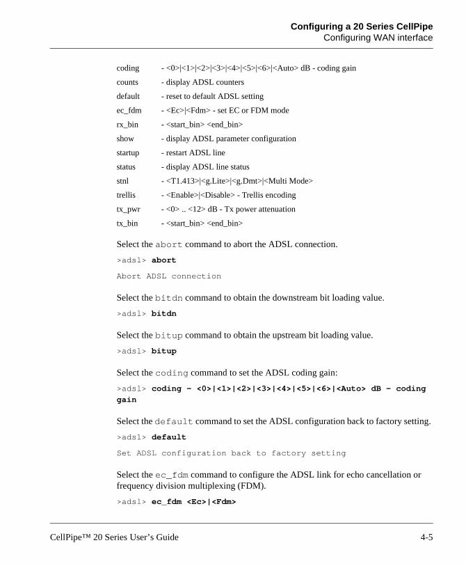
coding - <0>|<1>|<2>|<3>|<4>|<5>|<6>|<Auto> dB - coding gain
counts - display ADSL counters
default - reset to default ADSL setting
ec_fdm - <Ec>|<Fdm> - set EC or FDM mode
rx_bin - <start_bin> <end_bin>
show - display ADSL parameter configuration
startup - restart ADSL line
status - display ADSL line status
stnl - <T1.413>|<g.Lite>|<g.Dmt>|<Multi Mode>
trellis - <Enable>|<Disable> - Trellis encoding
tx_pwr - <0> .. <12> dB - Tx power attenuation
tx_bin - <start_bin> <end_bin>
Select the abort command to abort the ADSL connection.
>adsl> abort
Abort ADSL connection
Select the bitdn command to obtain the downstream bit loading value.
>adsl> bitdn
Select the bitup command to obtain the upstream bit loading value.
>adsl> bitup
Select the coding command to set the ADSL coding gain:
>adsl> coding - <0>|<1>|<2>|<3>|<4>|<5>|<6>|<Auto> dB - coding
gain
Select the default command to set the ADSL configuration back to factory setting.
>adsl> default
Set ADSL configuration back to factory setting
Select the ec_fdm command to configure the ADSL link for echo cancellation or frequency division multiplexing (FDM).
>adsl> ec_fdm <Ec>|<Fdm>
CellPipe™ 20 Series User’s Guide 4-5

Configuring a 20 Series CellPipeConfiguring WAN interface
Select the rx_bin command to limit the bin number used for special configurations in the receive signal. Values for bin numbers are between 1 to 255.
>adsl> rx_bin - <start_bin> <end_bin>
Select the show command to display the ADSL parameter configuration. For example:
>adsl> show
ADSL setting: Current IneffectiveLocal line code MULTIMODE MULTIMODETrellis encoding Enabled EnabledEC/FDM mode FDM FDMCoding gain AUTO 2 dBTransmit Power Attenuation 0 dB 0 dBTx Start bin 6 (H) 6 (H)Tx End bin 1f (H) 1f (H)Rx Start bin 20 (H) 3 (H)Rx End bin ff (H) 4 (H)
Select the startup command to restart the ADSL connection.
>adsl> startup
start to re-Sync. ...
Select the status command to display the ADSL parameter configuration. For example:
>adsl> status
ADSL Firmware version ANNEX_A CPE 41000
OP state handshake
Last Failed Status (0)
Start Progress a0
Watchdog Timer 53
Line code G.DMTFraming_Overhead_actual 0
Trellis <disable>
AS0_Dn_Bytes_Actual 0
4-6 CellPipe™ 20 Series User’s Guide

Configuring a 20 Series CellPipeConfiguring LAN interface
AS0_Dn_Latency_Actual <interleave>
LS0_Up_Bytes_Actual 0
LS0_Up_Latency_Actual <interleave>
Fast_R_Up_Actual 0
Interleave_S_Up_Actual 0
Interleave_D_Up_Actual 0
Interleave_R_Up_Actual 0
Fast_R_Dn_Actual 0
Interleave_S_Dn_Actual 0
Interleave_D_Dn_Actual 0
Interleave_R_Dn_Actual 0
Select the stnl command to configure the local ADSL coding type.
>adsl> stnl - <T1.413>|<g.Lite>|<g.Dmt>|<Multi-Mode>
Select the trellis command to enable or disable Trellis encoding.
>adsl> trellis <Enable>|<Disable>
Select the tx_pwr command to configure the transmitted power attentuation for a range between 0 dB and 12 dB.
>adsl> tx_pwr <0> .. <12>
Select the tx_bin command to allow the user to limit bins used for special configuration in the transmitted signal.
> adsl> tx_bin - <start_bin> <end_bin>
Configuring LAN interfaceThis section provides menus for configuring the LAN interface in both bridging and routing mode.
Configuring LAN interface in bridging mode
The following is a list of the menus available under the lan command in bridging mode:
CellPipe™ 20 Series User’s Guide 4-7

Configuring a 20 Series CellPipeConfiguring LAN interface
fullduplex - fullduplex <Disable>|<Enable>
setip - setup the IP address, and subnet mask for
Ethernet connection
show - show LAN configuration
Select the fullduplex command to enable or disable fullduplex.
>lan> fullduplex <Disable>|<Enable>
Select the setip command to set up the IP address and subnet mask for the LAN link. For example:
>lan> setip 192.168.2.32
Set a new IP address = 192.168.2.32 and
Subnet mask is default = 255.255.255.0
Select the show command to display the current configuration of IP setting. For example:
>lan> show
Ethernet IP = 192.168.2.32 and
Subnet mask is default = 255.255.255.0
FullDuplex : Disable
Configuring LAN interface in routing mode
The following is a list of the menus available under the lan command in routing mode:
dhcpclient - set dhcp client configuration
dhcpserver - set dhcp server configuration
fullduplex - fullduplex <Disable>|<Enable>
setdhcp - set dhcp operation
setip - setup the IP address, and subnet mask for
Ethernet connection
show - show LAN configuration
Select the dhcpclient command to set up the dhcp client configuration.
>lan> dhcpclient <lease time>
4-8 CellPipe™ 20 Series User’s Guide

Configuring a 20 Series CellPipeConfiguring the manage command
Select the dhcpserver command to configure the range of IP addresses that are associated with the subnet mask used for the DHCP server.
>lan> dhcpserver <range1 startIP> <range1 endIP> [<range2
startIP> <range2 endIP>] [<max-lease-time>]
- dhcpserver dns <dns ip1> [<dns ip2>]
Select the setdhcp command to set the DHCP mode of the unit.
>lan> setdhcp <server|client|disable>
Select the setip command to set the the IP address and subnet mask for the link.
>lan> setip <etherip[/<masknum>] [subnet mask]>|<dhcp>
Select the show command to display the LAN configuration. For example:
>lan> show
Ethernet ip: 149.198.65.46
Subnet mask: 255.255.255.0
FullDuplex:Enable
DHCP current setting : disable.
DHCP ineffective setting : disable.
Configuring the manage commandThe manage command allows you to set the user password. When user enables a password, the unit will time out after 10 minutes if there is no activity. The password has to be re-entered to resume activity.
>manage> setpass
Password disabled
New Password:<password>
Configuring the mode commandThe mode command allows you to select for either the bridging or the routing mode of operation.
CellPipe™ 20 Series User’s Guide 4-9
Configuring a 20 Series CellPipeConfiguring the quick command
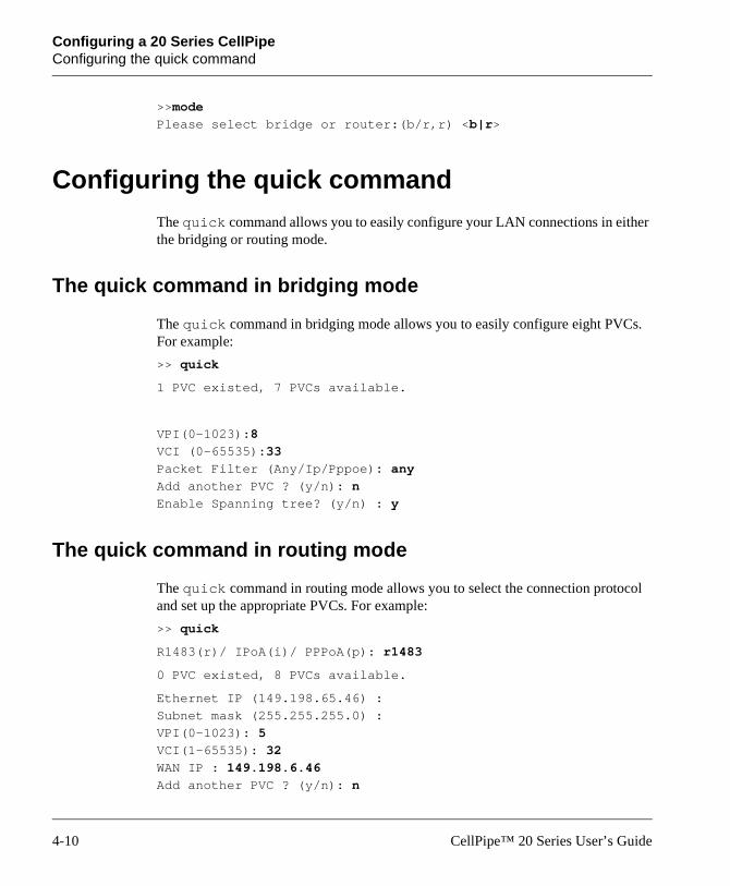
>>mode
Please select bridge or router:(b/r,r) <b|r>
Configuring the quick commandThe quick command allows you to easily configure your LAN connections in either the bridging or routing mode.
The quick command in bridging mode
The quick command in bridging mode allows you to easily configure eight PVCs. For example:
>> quick
1 PVC existed, 7 PVCs available.
VPI(0-1023):8
VCI (0-65535):33
Packet Filter (Any/Ip/Pppoe): any
Add another PVC ? (y/n): n
Enable Spanning tree? (y/n) : y
The quick command in routing mode
The quick command in routing mode allows you to select the connection protocol and set up the appropriate PVCs. For example:
>> quick
R1483(r)/ IPoA(i)/ PPPoA(p): r1483
0 PVC existed, 8 PVCs available.
Ethernet IP (149.198.65.46) :
Subnet mask (255.255.255.0) :
VPI(0-1023): 5
VCI(1-65535): 32
WAN IP : 149.198.6.46
Add another PVC ? (y/n): n
4-10 CellPipe™ 20 Series User’s Guide

Configuring a 20 Series CellPipeConfiguring the r1483 command
>>quick
R1483(r)/ IPoA(i)/ PPPoA(p): ipoa
0 PVC existed, 8 PVCs available.
Ethernet IP (149.198.65.46) :
Subnet mask (255.255.255.0) :
VPI(0-1023): 5
VCI(1-65535): 33
WAN IP : 148.198.6.46
Gateway : 148.198.6.90
>>quick
R1483(r)/ IPoA(i)/ PPPoA(p): pppoa
0 PVC existed, 1 PVC available.
Ethernet IP (149.198.65.46) :
Subnet mask (255.255.255.0) :
VPI(0-1023): 5
VCI(1-65535): 34
Authentication( PAP(p)/CHAP(c)/None(n) ): p
User name: Lucent
Password: *******
Retype password: *******
Configuring the r1483 commandYou can configure the r1483 command for either bridging or routing mode.
The r1483 command in bridging mode
The following is a list of menus under the r1483 command in the bridging mode:
delpvc - delete VPI and VCI
pfilter - set packet filter type
setpvc - set VPI and VCI for bridge mode
setqos - set class
CellPipe™ 20 Series User’s Guide 4-11

Configuring a 20 Series CellPipeConfiguring the r1483 command
setspan - <Enable>|<Disable> spanning tree
show - show RFC1483 configuration
Select the delpvc command to delete one or all PVCs.
>r1483> delpvc <all>|[<vpi>/]<vci>
Select the pfilter command to set the packet filter type.
>r1483> pfilter [<vpi>/]<vci> <any|ip|pppoe|igmp|none>
Select the setpvc command to set the PVCs in bridging mode.
>r1483> setpvc [<vpi>/]<vci> [llc/vcmux]
Select the setqos command to set the class for quality of service.
>r1483> setqos [<vpi>/]<vci> <ubr|cbr|vbr(nrt)>
Select the show command to display the RFC1483 configuration.
FUNCTION VPI/VCI CLASS LLC/VCMUX Spanning Pkt Filter
Rfc1483 8/35 ubr LLC Enable ANY
The r1483 command in routing mode
The following is a list of menus under the r1483 command in the routing mode:
delwanip - delete VPI and VCI
setqos - set class
setrip - set RIP configuration
setwanip - set PVC and Wan IP for routing mode
show - show RFC1483 configuration
Select the delwanip command to delete one or all PVCs.
>r1483> delpvc <all>|[<vpi>/]<vci>
Select the setqos command to set the class for quality of service.
>r1483> setqos [<vpi>/]<vci> <ubr|cbr|vbr(nrt)>
Select the setrip command to set the PVC for RIP.
>ipoa> setrip [<vpi>/]<vci> <1|2|1&2|0>
4-12 CellPipe™ 20 Series User’s Guide
Configuring a 20 Series CellPipeConfiguring the dnsrelay command
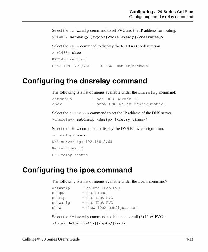
Select the setwanip command to set PVC and the IP address for routing.
>r1483> setwanip [<vpi>/]<vci> <wanip[/<masknum>]>
Select the show command to display the RFC1483 configuration.
> r1483> show
RFC1483 setting:
FUNCTION VPI/VCI CLASS Wan IP/MaskNum
Configuring the dnsrelay commandThe following is a list of menus available under the dnsrelay command:
setdnsip - set DNS Server IPshow - show DNS Relay configuration
Select the setdnsip command to set the IP address of the DNS server.
>dnsrelay> setdnsip <dnsip> [<retry times>]
Select the show command to display the DNS Relay configuration.
>dnsrelay> show
DNS server ip: 192.168.2.65
Retry times: 3
DNS relay status
Configuring the ipoa commandThe following is a list of menus available under the ipoa command>
delwanip - delete IPoA PVC
setqos - set class
setrip - set IPoA PVC
setwanip - set IPoA PVC
show - show IPoA configuration
Select the delwanip command to delete one or all (8) IPoA PVCs.
>ipoa> delpvc <all>|[<vpi>/]<vci>
CellPipe™ 20 Series User’s Guide 4-13
Configuring a 20 Series CellPipeConfiguring the pppoa command
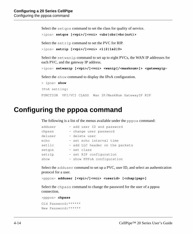
Select the setqos command to set the class for quality of service.
>ipoa> setqos [<vpi>/]<vci> <ubr|cbr|vbr(nrt)>
Select the setrip command to set the PVC for RIP.
>ipoa> setrip [<vpi>/]<vci> <1|2|1&2|0>
Select the setwanip command to set up to eight PVCs, the WAN IP addresses for each PVC, and the gateway IP address.
>ipoa> setwanip [<vpi>/]<vci> <wanip[/<masknum>]> <gatewayip>
Select the show command to display the IPoA configuration.
> ipoa> show
IPoA setting:
FUNCTION VPI/VCI CLASS Wan IP/MaskNum GatewayIP RIP
Configuring the pppoa commandThe following is a list of the menus available under the pppoa command:
adduser - add user ID and password
chpass - change user password
deluser - delete user
echo - set echo interval time
setllc - add LLC header on the packets
setqos - set class
setrip - set RIP configuration
show - show PPPoA configuration
Select the adduser command to set up a PVC, user ID, and select an authentication protocol for a user.
>pppoa> adduser [<vpi>/]<vci> <userid> [<chap|pap>]
Select the chpass command to change the password for the user of a pppoa connection.
>pppoa> chpass
Old Password:******
New Password:******
4-14 CellPipe™ 20 Series User’s Guide

Configuring a 20 Series CellPipeConfiguring the pat command
Confirm Password again: ******
Pass has been changed
Select the deluser command to delete a user of a pppoa connection.
>pppoa> deluser
Select the echo command to input the echo time interval and enable LCP echo cancellation.
>pppoa> echo <interval time>
Select the setllc command to enable or disable logic link control (LLC).
>pppoa> setllc <e>nable|<d>isable
Select the setqos command to set the class for quality of service.
>pppoa> setqos [<vpi>/]<vci> <ubr|cbr>
Select the setrip command to set up for RIP.
>pppoa> setrip <1|2|1&2|0>
Select the show command to display the PPPoA routing setting.
>pppoa> show
PPPoA dial out setting:
Function VPI/VCI Class PCR (Kbits) UserID/Auth
PPPoA 2/32 ubr 640 Lucent/CHAP
LLC = Disable Echo interval time: 60 s
Configuring the pat commandThe following is a list of the menus available under the pat command:
addpatin - add incoming PAT table
delpatin - delete incoming PAT table
setpat - enable or disable PAT function
show - show PAT configuration
CellPipe™ 20 Series User’s Guide 4-15

Configuring a 20 Series CellPipeConfiguring the pat command
Select the addpatin command to enable a local server’s IP address to be used as a WAN access port.
>pat> addpatin <pppoa|wanip> <port>/<udp|tcp> <serverip>
Note: Prior to setting the local server as a WAN access port, you have to enable the PAT function. See the setpat command below.
Select the delpatin command to disable the local server as a WAN access port.
>pat> delpatin <all>|<number>
Select the setpat command to enable or disable a specific PAT interface.
>pat> setpat <pppoa|wanip> <e>nable|<d>isable
Select the show command to display the Pat configuration.
>pat> show
PAT enabled interface:
Interface IP address
IPoA 210.62.2.195
PPPoA?.?.?.?
PAT incoming table
No. i/f name|WAN IP Port/Protocol Server IP
1 pppoa 434/udp 192.62.2.134
2 210.62.2.195 232/tcp 192.62.2.166
4-16 CellPipe™ 20 Series User’s Guide

CellPipe™ 20 Series User’s Guide
5
Upgrading System SoftwarePreparing to upgradeTo upgrade system software for a CellPipe 20 Series unit, you need to download to your computer the appropriate zipped file of the latest software release. Establish a serial connection between the unit and your computer for access to the CLI and also establish an Ethernet connection to the unit. Be sure the unit and your computer are configured properly so that you can successfully “ping” the unit from your computer or vice versa.
Obtaining software You can obtain the latest software release from the Lucent Technologies eSight™ Service Center at http://www.esight.com.
Note: Be sure you use the correct loads to upgrade. Your unit can lose all or part of its configuration if the wrong loads are used.
! Caution: Do not upgrade to an earlier software version. Newer units will not function properly when older software is loaded.
Preparing to upgrade. . . . . . . . . . . . . . . . . . . . . . . . . . . . . . . . . . . . . . . . . . . . . . . 5-1
Obtaining software . . . . . . . . . . . . . . . . . . . . . . . . . . . . . . . . . . . . . . . . . . . . . . . . 5-1
Upgrading software . . . . . . . . . . . . . . . . . . . . . . . . . . . . . . . . . . . . . . . . . . . . . . . 5-2
5-1

Upgrading System SoftwareUpgrading software
Upgrading softwareFollow the procedure below to upgrade software:
1 Extract the loads from eSight to your computer.
2 Establish an Ethernet connection between the unit and your computer.
3 Set up IP addresses on the unit and your computer such that you can successfully ping the unit.
4 Under the DOS prompt on your computer, enter the path to the directory containing the extracted loads and a file named xupgrade.bat.
5 To start the upgrade, execute command xupgrade <ipaddress of unit>, for example:
C:\> xupgrade 149.198.65.46
Note: There is no need to back up your current configuration. Using the xupgrade.bat file for upgrading will retain your current configuration. The upgrading process might last as long as 60 seconds.
6 Then enter the restart command to reboot the unit.
7 Lastly enter the save command to save the new upgrade.
Note: Maintain stable power to the unit while upgrading software. If power fails during the upgrading process, contents in the memory could be destroyed and the system will hang and no longer function.
5-2 CellPipe™ 20 Series User’s Guide

CellPipe™ 20 Series User’s Guide
Warranties and FCC Regulations
Product warranty1 Lucent Technologies warrants that the CellPipe unit will be free from defects in
material and workmanship for a period of twelve (12) months from date of shipment.
2 Lucent Technologies shall incur no liability under this warranty if:
– The allegedly defective goods are not returned prepaid to Lucent Technologies within thirty (30) days of the discovery of the alleged defect and in accordance with Lucent Technologies’ repair procedures; or
– Lucent Technologies’ tests disclose that the alleged defect is not due to defects in material or workmanship.
3 Lucent Technologies’ liability shall be limited to either repair or replacement of the defective goods, at Lucent Technologies’ option.
4 Lucent Technologies MAKES NO EXPRESS OR IMPLIED WARRANTIES REGARDING THE QUALITY, MERCHANTABILITY, OR FITNESS FOR A PARTICULAR PURPOSE BEYOND THOSE THAT APPEAR IN THE APPLICABLE Lucent Technologies USER'S DOCUMENTATION. Lucent Technologies SHALL NOT BE RESPONSIBLE FOR CONSEQUENTIAL, INCIDENTAL, OR PUNITIVE DAMAGE, INCLUDING, BUT NOT LIMITED TO, LOSS OF PROFITS OR DAMAGES TO BUSINESS OR BUSINESS
Product warranty . . . . . . . . . . . . . . . . . . . . . . . . . . . . . . . . . . . . . . . . . . . . . A-1
FCC Part 15 Notice . . . . . . . . . . . . . . . . . . . . . . . . . . . . . . . . . . . . . . . . . . . A-2
IC CS-03 Notice . . . . . . . . . . . . . . . . . . . . . . . . . . . . . . . . . . . . . . . . . . . . . . A-3
A-1

Warranties and FCC RegulationsFCC Part 15 Notice
RELATIONS. THIS WARRANTY IS IN LIEU OF ALL OTHER WARRANTIES.
Warranty repair1 During the first three (3) months of ownership, Lucent Technologies will repair
or replace a defective product covered under warranty within twenty-four (24) hours of receipt of the product. During the fourth (4th) through twelfth (12th) months of ownership, Lucent Technologies will repair or replace a defective product covered under warranty within ten (10) days of receipt of the product. The warranty period for the replaced product shall be ninety (90) days or the remainder of the warranty period of the original unit, whichever is greater. Lucent Technologies will ship surface freight. Expedited freight is at customer’s expense.
2 The customer must return the defective product to Lucent Technologies within fourteen (14) days after the request for replacement. If the defective product is not returned within this time period, Lucent Technologies will bill the customer for the product at list price.
Out-of warranty repair
Lucent Technologies will either repair or, at its option, replace a defective product not covered under warranty within ten (10) working days of its receipt. Repair charges are available from the Repair Facility upon request. The warranty on a serviced product is thirty (30) days measured from date of service. Out-of-warranty repair charges are based upon the prices in effect at the time of return.
FCC Part 15 Notice
! Warning: This equipment has been tested and found to comply with the limits for a Class B digital device, pursuant to Part 15 of the FCC rules. These limits are designed to provide reasonable protection against harmful interference when the equipment is operated in a residential environment. This equipment generates, uses, and can radiate radio frequency energy, and, if not installed and used in accordance with the instruction manual, may cause harmful interference to radio communications. Operation of this equipment in a residential area is unlikely to cause harmful
A-2 CellPipe™ 20 Series User’s Guide

Warranties and FCC RegulationsIC CS-03 Notice
interference. But if it does, the user will be required to correct the interference at his or her own expense.
The authority to operate this equipment is conditioned by the requirement that no modifications will be made to the equipment unless the changes or modifications are expressly approved by Lucent Technologies.
IC CS-03 NoticeThe Industry Canada label identifies certified equipment. This certification means that the equipment meets certain telecommunications network protective, operational, and safety requirements as prescribed in the appropriate Terminal Equipment Technical Requirements document(s). The Department does not guarantee that the equipment will operate to the user’s satisfaction.
Before installing this equipment, users should make sure that it is permissible to be connected to the facilities of the local telecommunications company. An acceptable method of connection must be used to install the equipment. The customer should be aware that compliance with the above conditions may not prevent degradation of service in some situations.
Repairs to certified equipment should be coordinated by a representative designated by the supplier. Any repairs or alterations made by the user to this equipment, or equipment malfunctions, may give the telecommunications company cause to request the user to disconnect the equipment.
Users should ensure for their own protection that the electrical ground connections of the power utility, telephone lines, and internal metallic water pipe system, if present, are connected together. This precaution may be particularly important in rural areas.
Warning: Users should not attempt to make such connections themselves, but should contact the appropriate electric inspection authority, or electrician, as appropriate.
CellPipe™ 20 Series User’s Guide A-3