Embed Size (px)
Citation preview
Rochester Institute of TechnologyRIT Scholar Works
Theses Thesis/Dissertation Collections
2011
Cellular network monitoring system based onsubscriber unitsVictor Silva
Follow this and additional works at: http://scholarworks.rit.edu/theses
This Thesis is brought to you for free and open access by the Thesis/Dissertation Collections at RIT Scholar Works. It has been accepted for inclusionin Theses by an authorized administrator of RIT Scholar Works. For more information, please contact [email protected].
Recommended CitationSilva, Victor, "Cellular network monitoring system based on subscriber units" (2011). Thesis. Rochester Institute of Technology.Accessed from
CELLULAR NETWORK MONITORING SYSTEM BASED ON SUBSCRIBER UNITS
By
Víctor Silva
Thesis submitted in partial fulfillment of the requirements for the degree of Master of Science in
Networking and System Administration
Rochester Institute of Technology
B. Thomas Golisano College of
Computing and Information Sciences
2
Master of Science in Networking and System Administration
Thesis Approval Form
Student Name: _Víctor Silva____________________________ CELLULAR NETWORK MONITORING SYSTEM Thesis Title: BASED ON SUBSCRIBER UNITS____________ Thesis Committee
Name Signature Date Charles Border
Chair Sumita Mishra
Committee Member Giovanny Heredia
Committee Member
3
Thesis Reproduction Permission Form
Rochester Institute of Technology
B. Thomas Golisano College
of
Computing and Information Sciences
Master of Science in
Networking and System Administration
CELLULAR NETWORK MONITORING SYSTEM BASED ON SUBSCRIBER UNITS
I, Víctor Silva, hereby grant permission to the Wallace Library of the Rochester Institute of Technology to reproduce my thesis in whole or in part. Any reproduction must not be for commercial use or profit. Date: ___________ Signature of Author: __________________________
4
TABLE OF CONTENTS
1. INTRODUCTION 6
Statement of the problem 6
Motivation of the study 6
Potential benefits 7
Personal goals 7
Summary 8
2. LITERATURE REVIEW 8
3. LITERATURE REVIEW REVISITED 11
Management Framework 11
Software Development Language/Tool 12
RIL Layer 12
4. CELLULAR NETWORK MONITOR SYSTEM DESIGN 13
Architectural Description 14 System Context 14 Application Modules 15 Connectors 16
System Architectural Diagram 16
Agent Design 17 Agent Flow Chart 17 Agent Flow Chart – Communication Thread 18 Agent Flow Chart – Data Retriever Thread 19 Agent Flow Chart – Timer Thread 20
Server Design 21 Graphic User Interface 21 Command Page 21 Results Page 22 Map Page 23 Data Base 23
5. SYSTEM CONSTRUCTION 25
Cellular Agent Construction 25 SMS handling 31 Command dispatcher 33 Timer Thread 34
5
Server Construction 35 Cell Server Application 35 SMS Handling – Sending 35 SMS Handling – Receiving 38 XML Data 40
6. CONCLUSIONS 42
7. REFERENCES 43
6
1. Introduction
Statement of the problem
The normal approach to assess signal quality parameters in a wireless network requires
performing what is known as a drive test. A drive test consists on driving a vehicle
equipped with a wireless measurement toll box around the area of interest, in order to take
measures of several wireless signal parameters. Drive testing is a time consuming activity
often affected by external factors such as vehicular traffic congestion and others.
The slowness of the process makes this technique impractical when the goal is to measure
the impact caused by minor changes on the network; when you need something like a trial-
and-error approach; or if you are acting in a proactive way where trying to have an early
alert on signal degradation before clients complains start.
Motivation of the study
In the telecommunication industry, I have been involved in the operation and maintenance
of a wireless telephone network. For a mobile network operator the principal goal is to keep
the network working and delivering the right quality of service to costumers. In order to
achieve a good quality of service (QoS), it is necessary to monitor and control various
performance indicators by taking field measures periodically and comparing them with
previous collected data. These field measures can become unpractical when trying to
troubleshoot or when you are trying to keep an up to date status of the network signal
levels. The measure process takes long time and effort, especially when collecting data
from faraway sites.
7
I have always wondered whether it is possible to implement a system that might
avoid that tedious data acquisition process. On my first class at RIT, Research Methods, I
heard of a “sensor network” crazy idea, so I come out with the idea of creating a network of
sensors using the costumers’ mobile telephones as data collecting terminals.
A wireless network measurement system made of a right number of sensors randomly
distributed on the zone of interest might be a powerful tool. With this sort of sensor
network arrangement, it is possible to make quality of service measurements in a much
more efficient way than with traditional methods.
Potential benefits
Having a system that provides instant quality of service data from any remote location
should be a very useful tool for any mobile network operator. A sensor network approach
can improve data acquisition response time, becoming a valuable help on network
troubleshooting, maintenance, optimization, and quality of service assurance.
Personal goals
That brings me to my main goal in this project, which is to evaluate an alternative solution
for wireless network optimization. In this sense, I propose to evaluate the benefits of using
a sensor network approach to signal monitoring for telephone wireless network
optimization.
In order to accomplish this project, I will develop various pieces of software: a mobile
quality of service agent, a web based application, and an agent management application.
8
The mobile quality of service agent software will be installed on standards mobile
telephones and will be on charge of collecting the field data and send it to a server. The
web application will receive quality of service data from the mobiles agents and will store
this data on a database. Finally, I will develop an agent management application that will be
used to control and manage mobile agents via SMS commands.
Summary
In the remaining of this paper, I will walk through development considerations and give
detailed system description for a concept prove wireless network optimization tool. In
Section 2 related works on the matter are revisited under the light of the hands on
experience on this project. Section 3 is an introduction to cellular systems and quality of
service parameters for cellular networks. Section 4 describes the development process and
details system components. Finally in Section 5 I will present my conclusions.
2. Literature Review
There is few literature related to this specific theme, as far as I have found. In the following
paragraphs, I will introduce the concept of mobile quality of service agent (Mobile QoS
Agent) and present some research papers related to remote personal device management
(RPDM) such as personal telephones. Later I will depict two developing tools suited for
small devices programming.
A recent research [1] presents a novel approach for a wireless network measurement
solution based on a piece of software named Mobile QoS Agent. As described by Soldani
[1], this agent runs on standards mobile telephones where it performs quality of service
9
measures. The mobile agent is able to conduct all kind of different tests based on a
configurable profile installed on the phone. Since this measures are taken on the field and
using the actual costumer terminals, they allow an accurate representation of the service
quality experienced by costumers. The discussed technique proved that it is possible to turn
thousands of costumer’s phones into quality measure stations. The solution proposed in [1]
is mean to be used by mobile network operators as a network planning and optimization
tool. Among the benefits of that approach they cited that “the measurement results
drastically reduce the needs of traditional drive or walk tests” [1].
A pilot test that included the installation of Mobile Quality of Service Agent in ten
headsets (Nokia 6630, 6680) connected to GPS via Bluetooth was conducted. Results
indicate that data collection through the use of Mobile QoS Agents deployed on costumer’s
mobile equipment to collect performances data “is very likely to be the key solution for
wireless network service assurance” [1].
The development of a mobile agents based wireless optimization system requires special
tools. A programming language optimized for small devices and a standardized language
that could support communication between the mobile units and the central server. The
following paragraphs explore these aspects.
In [2] we can see the design description for a remote device management framework
optimized for personal devices. In the study various device management systems were
evaluated based on five categories: expressive power, system load (computational and
memory), network load, security and device IQ. The expressive power is a measure of the
flexibility of the technique and the device IQ is a measure of in what extend the device is in
10
control of the situation within a management session. The other three categories are self
explanatory. In [2] results, OAM DM emerge as the best option for remote network
management technique to manage the communication between mobile agents.
OAM DM (Open Mobile Alliance Device Management) was at the beginning an initiative
by Ericsson, IBM, Lotus, Motorola, Nokia, Palm Inc., Psion and Starfish Software. It goal
was “to accelerate the market's vision of ubiquitous data access from any device to any
networked data“[3]. OAM extensions allow the operator to perform management actions on
manageable objects of the remote managed device. This way the operator can perform all
sorts of device management tasks: device configurations, read and set parameters,
executing, installing and upgrading software.
OAM DM offer fairly good expression power and has very good performance.
In [4] we find the following list of OMA DM capable devices:
● Alcatel: Alcatel One Touch 715
● Ericcson: T39, T68
● Motorola: V300, V400, V500
● Nokia: 3300, 3595, 3650, 3660, 6108, 62xx, 6600,
6800/20, 7200/50/50i/70/80, 7650, 9500, N-Gage
● Panasonic: X70
● Siemens: M55, M56, S55, S56, SL56, C65, SX1
● Sony Ericsson: P800, P900, 700, 700i, T68i, T610, T618,
T630, Z600, Z1010
11
For the software development we will use the Java 2 Micro Edition platform. This is a Java
platform especially conceived for no conventional consumer devices. It is suited for devices
with characteristic like limited memory, limited processing power and small display areas
[5]. All this makes this platform perfect for mobile telephone applications.
The lack of commercially available solutions and the limited number of research on this
subject reveal a great opportunity for further investigation. While the system proposed in
[1] is a valid solution for UMTS systems, more research is needed for a CDMA2000
wireless network implementation. Other related issues might be the development of mobile
agents based application such as costumer service, costumer surveys, user data backup,
among others.
3. Literature Review Revisited
Various planned work-roads on the original proposal were abandoned. Some of them were
not necessary and others were no applicable under current scenario.
Management Framework
While certainly a robust management tool is a must in a real life commercial
implementation where the number of remote units to configure and maintain will be on the
thousands, in a concept prove implementation, as the one this project is aimed to, the added
complexity and restrictions derived from the use of those platforms made them unpractical.
In place of elaborated platforms I will be using the nearly ubiquitous SMS platform with a
truly elemental protocol based on custom formatted text SMS messages.
12
Software Development Language/Tool
Due to equipment availability I decided to use Visual Studio Development Suite and C#
programming language.
RIL Layer
The Radio Interface Layer provides the interface between the radio hardware and device
drivers from OEMs (Original Equipment Manufactures) on the cellular market. In this
sense the RIL layer creates an abstraction that makes possible for cellular manufactures
accommodate different radio into their equipments using a single driver that follows the
RIL abstraction [6].
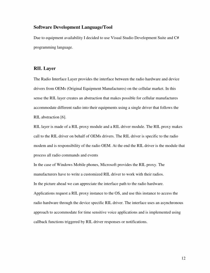
RIL layer is made of a RIL proxy module and a RIL driver module. The RIL proxy makes
call to the RIL driver on behalf of OEMs drivers. The RIL driver is specific to the radio
modem and is responsibility of the radio OEM. At the end the RIL driver is the module that
process all radio commands and events
In the case of Windows Mobile phones, Microsoft provides the RIL proxy. The
manufacturers have to write a customized RIL driver to work with their radios.
In the picture ahead we can appreciate the interface path to the radio hardware.
Applications request a RIL proxy instance to the OS, and use this instance to access the
radio hardware through the device specific RIL driver. The interface uses an asynchronous
approach to accommodate for time sensitive voice applications and is implemented using
callback functions triggered by RIL driver responses or notifications.
13
4. Cellular Network Monitor System Design
The Cellular Network Monitor (CNM) attempts to take advantage of customer premise
equipments (CPE) to measure quality of service parameters related to last mile
connectivity. On a cellular network CPE are commonly known as mobile phones or cellular
phones and “last mile” is also referred to with the term “mobile mile”.
The technological advances on microelectronics, physics, and other fields have lead to
increasingly computer miniaturization and therefore increasingly computer capacity for
electronic devices. Nowadays cellular phones have become truly mini computers capable of
execute the more diverse tasks and event with multitasking capacity in most cases.
Under these conditions a cellular network increasingly resembles a traditional computer
network: every phone unit packs the computational and connectivity capacities of a
computer network host. CNM uses a piece of software named Cellular Agent that is to run
14
on costumers’ phones. Once running the Cellular Agent will receive commands, execute
requested tasks, and reply with results to a central server, named the Server Agent. The
other component of the system is a central server which includes a Web Server, Web based
graphic user interface (GUI), a Database Server, and server side running scripts to backs
application’s logic and system’s components interconnections.
Architectural Description
System Context
The Cellular Network Monitoring System is aimed to help on cellular system monitoring
and quality assurance. The system is build with the goal of reducing the cost in time,
resources and work invested in the collection of the field data needed to measure signal
quality in a cellular network. The used approach takes advantage of costumers’ handsets
and movement patterns to assists us in data collection. This is made possible by placing a
piece of code (software agent) in costumers’ cell phones with the capacity to collect on
field data measurements and transmit these measures to a central data gatherer application.
These software agents on mobile handsets are required to accept configuration messages
from a central server. This interaction should be ease by a management module with a user
friendly interface. Configurable options must include a way to select the data collection
routine to execute and other important parameters such as time between measures. Handset
agents must allow user interaction in order to ease system test and debug.
15
Application Modules
CNM’s fundamental part is the software agent to be installed on costumers’ handsets. This
module construction is dependent on the handset (telephone) operating system and
supported technologies. On a final stage the module may be composed of two computer
programs, one responsible of agent-server interactions and the second one in charge of
actual measurements routines.
A communication manager module sits between software agents and the rest of the system
in order to facilitate data and control messages exchange, and to manage communication
channel security. A database administration module collects messages received from all
agents and dumps all the data on the central database through a database engine module.
This database administration module should also responds to data requirements from
system operators with data stored on the central database.
The application control module implements the application logic and dispatch users’
requests posted through the graphical user interface (GUI) module. This GUI is
implemented as a web application via internet browsers on users’ computers and represents
the human/computer interaction component.
16
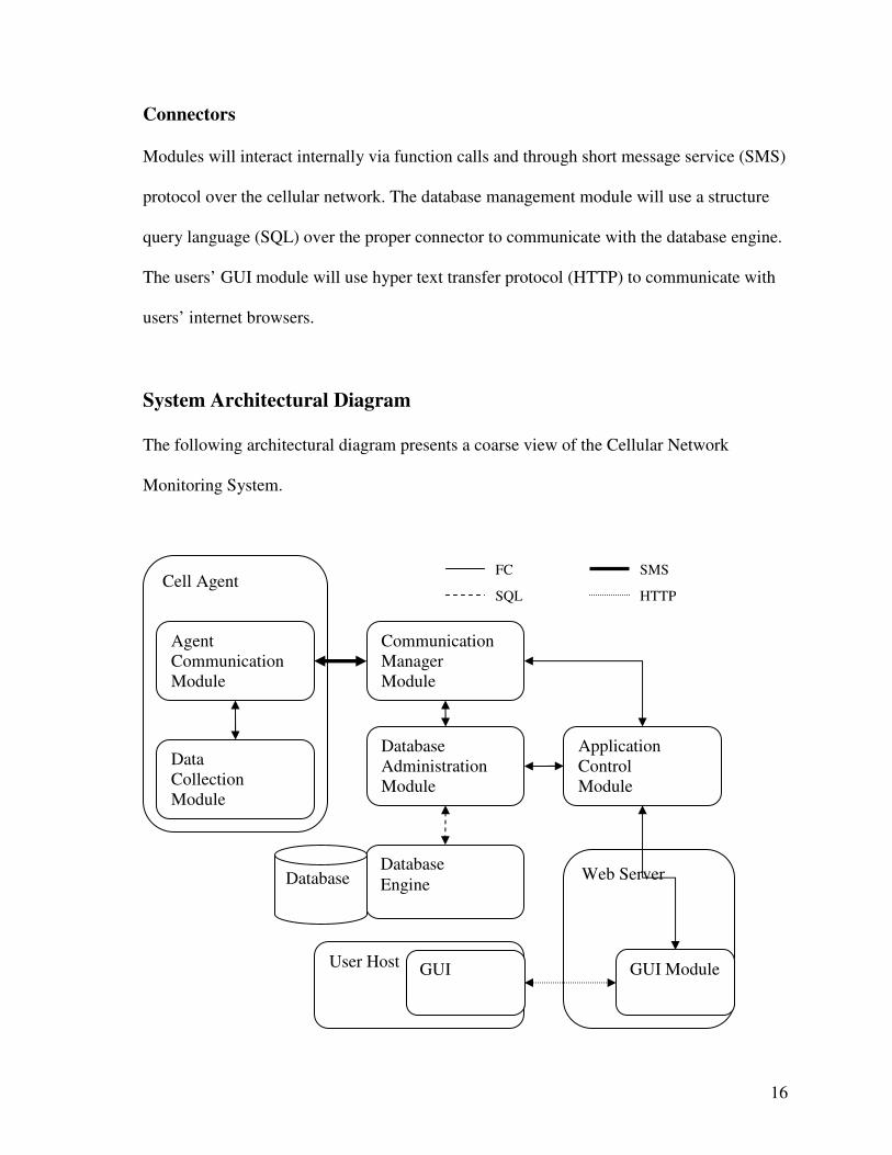
Connectors
Modules will interact internally via function calls and through short message service (SMS)
protocol over the cellular network. The database management module will use a structure
query language (SQL) over the proper connector to communicate with the database engine.
The users’ GUI module will use hyper text transfer protocol (HTTP) to communicate with
users’ internet browsers.
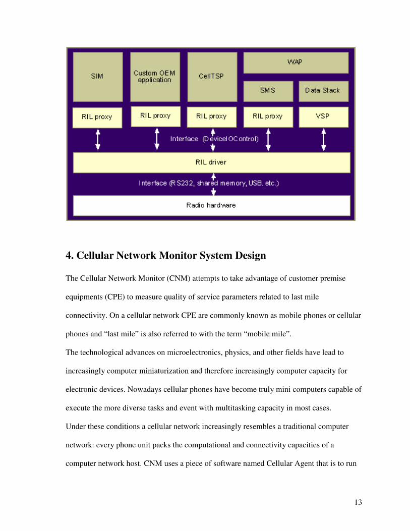
System Architectural Diagram
The following architectural diagram presents a coarse view of the Cellular Network
Monitoring System.
User Host
Cell Agent
Agent Communication Module
Data Collection Module
Database Administration Module
Communication Manager Module
Database Engine Database
Application Control Module
Web Server
GUI Module GUI
FC
SQL
SMS
HTTP
17
Agent Design
The central part of the system is the Cellular Agent. The Cellular Agent must be capable of
measuring basic quality of service parameters. The Cellular Agent must be capable of
receiving a command and queue it to start execution at the requested time. This queue
capacity is essential to sync measuring times among different agents running on different
cellular equipments. Once a new task has been queue the agent must be able to accept new
commands from the server. This module will run on limited resource equipment therefore
care must be take not to compromise capacity more than needed. Multithreading an Event
Driven approaches where used to accomplish Cellular Agent requirements with minimum
system load.
Agent Flow Chart
Event driven system are by its nature cumbersome to picture using flow charts, even in the
case of simple systems. The reason is that events are external to the system and normally
occur in an unexpected time and pattern. The following is an effort to show the
functionality of the Cellular Agent.
18
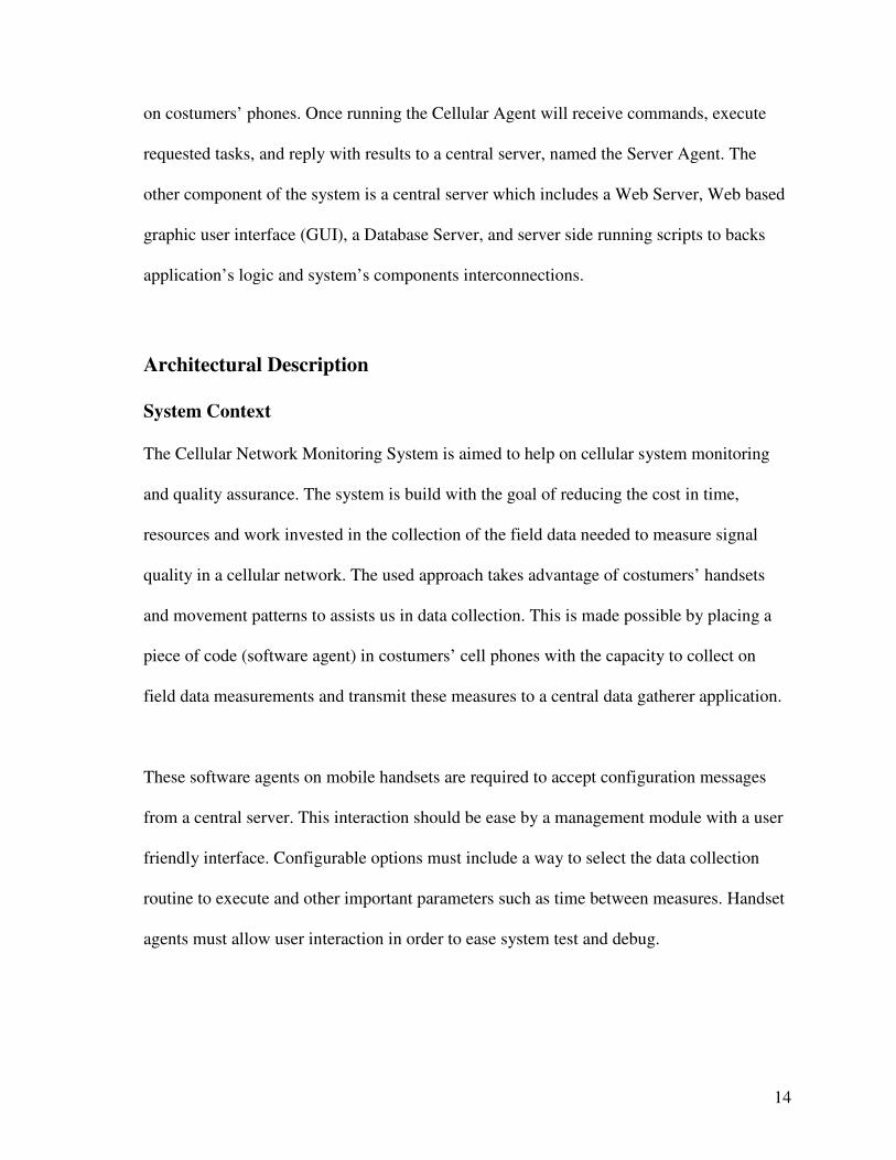
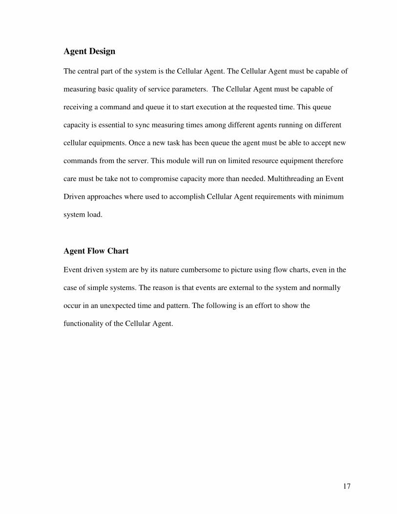
Agent Flow Chart – Communication Thread
CommunicationThread
Init- Read central server configuration (from config file?)- Hello to central server- Set- Register handler for Received SMS event
Valid Command(SMS from sever)
No
Yes
Wait for newcommand
(from server)
Wait for DataReady
(from DataRetriever)
Switch Command
case Command 1case Command 2case Command 3case Command 4
-Register Data ReadyEvent Handler
-Send Command toData Retriever
(Start a RetrieverThread)
Data Ready Event
Read data fromshared repository/ Send data (SMS
to server)
Reset Data
SMS Received Event
Figure 4-1
Parallel lines on the diagram represent the “waiting for asynchronous events” state.
19
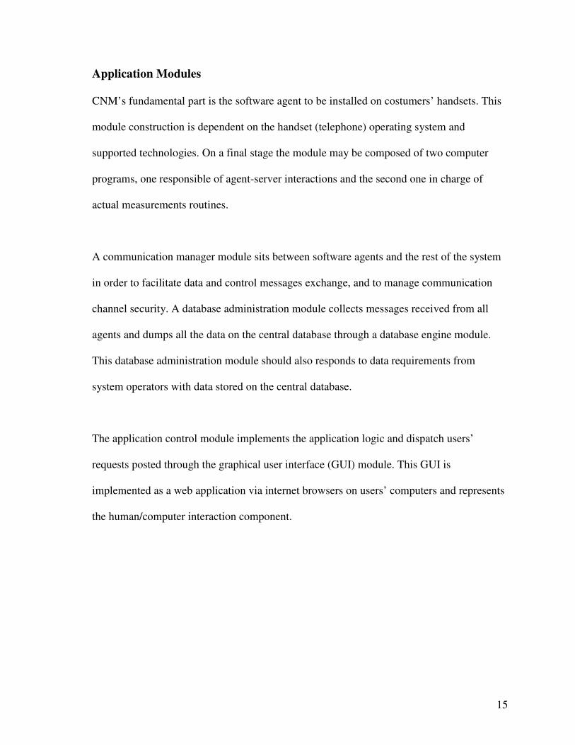
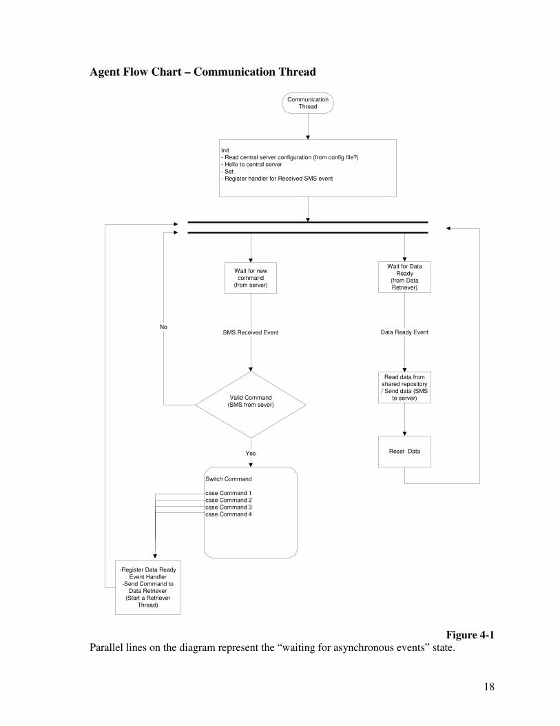
Agent Flow Chart – Data Retriever Thread
Data RetrieverThread
Count Reached Event
-Accept new command-Init Repeat Count
-Create Comm Channel withOS Timer Service (Count
Reached Event)-Prog. and Start System Timer
(Start Timer Thread)
-Dispose Timer-Set Data Ready
Event(to Communication
Module)
-Wait for CountReached Event
(from TimerThread)
End
Figure 4-2
The Data Retriever Thread is in charge of programming system timer to meet the received command conditions of measuring routine start time and intervals. It communicates with Communication Thread by triggering the Data Ready event.
20
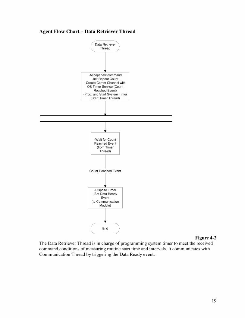
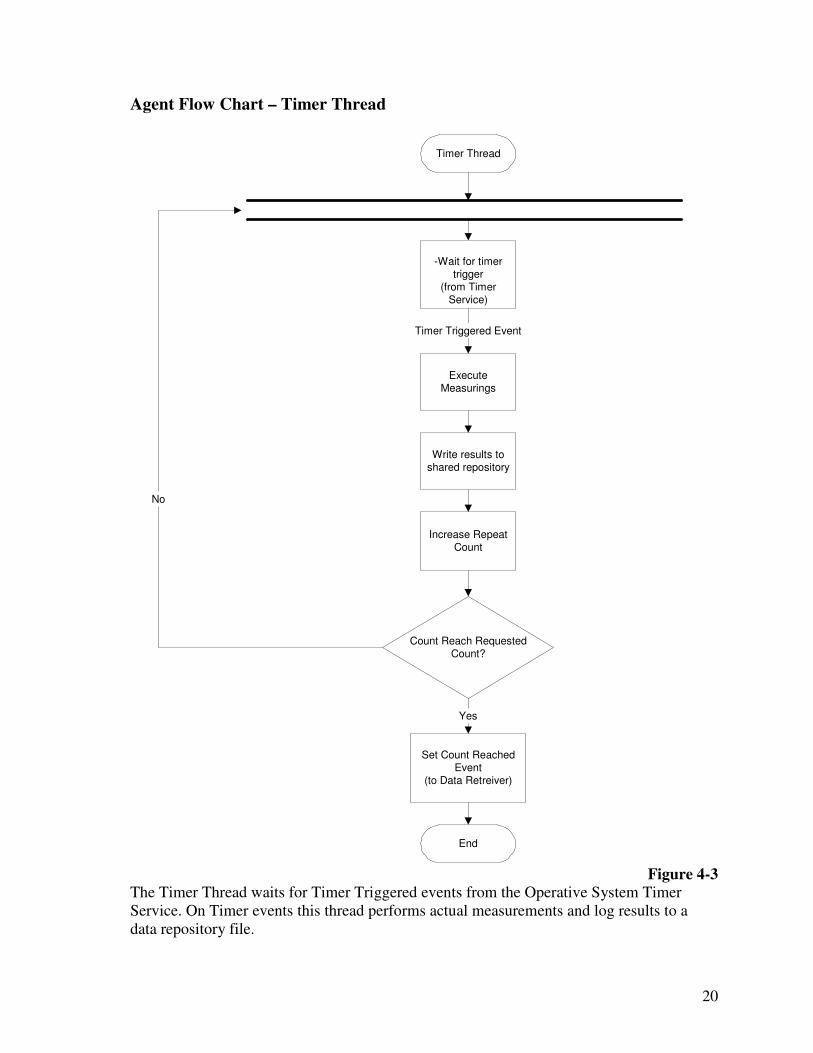
Agent Flow Chart – Timer Thread
Timer Thread
ExecuteMeasurings
No
Write results toshared repository
Set Count ReachedEvent
(to Data Retreiver)
Increase RepeatCount
Count Reach RequestedCount?
Timer Triggered Event
-Wait for timertrigger
(from TimerService)
Yes
End
Figure 4-3
The Timer Thread waits for Timer Triggered events from the Operative System Timer Service. On Timer events this thread performs actual measurements and log results to a data repository file.
21
Server Design
Server design considerations comprise database design, graphic user interface, and
application logic.
Graphic User Interface
The user interface is a key component in a commercial tool. It greatly affects the user
experience with the application and can also affect the utility level of the application. In this
case the GUI is kept very simple with only the needed functionality to prove the Cellular
Network Monitor concept.
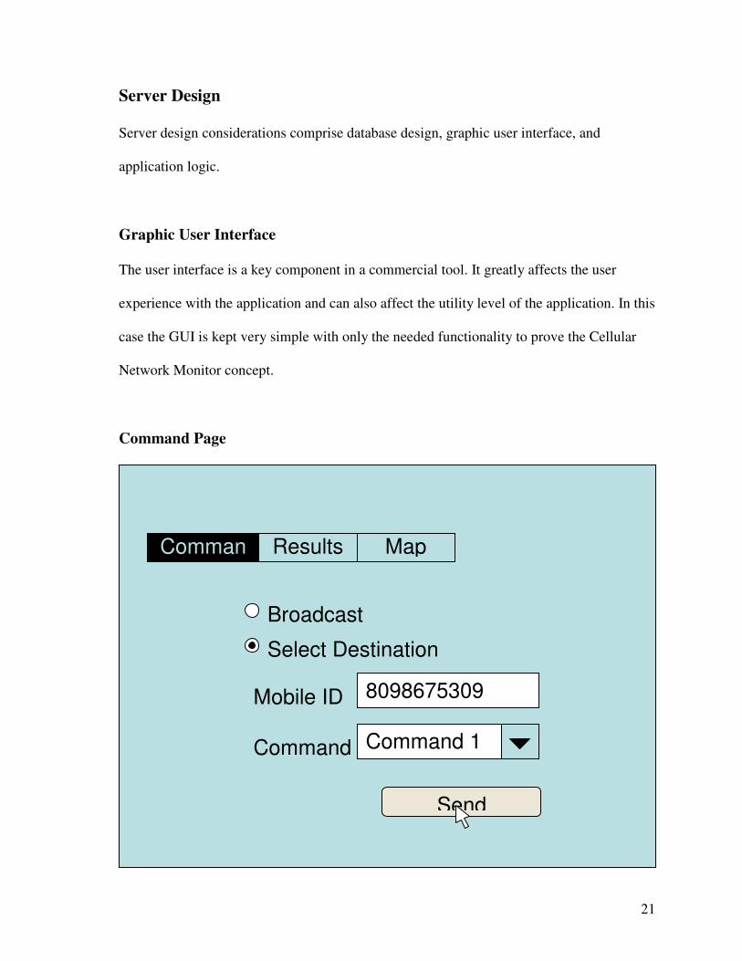
Command Page
Broadcast
Select Destination
Mobile ID 8098675309
Comman Results Map
Command Command 1
Send
22
The command page interface allows the user to send a “broadcast” to al agents or single
messages to a particular mobile agent. For ease of use the commands can be chosen from a
drop down menu.
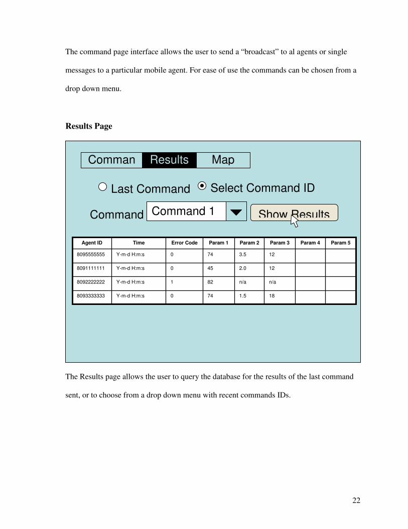
Results Page
The Results page allows the user to query the database for the results of the last command
sent, or to choose from a drop down menu with recent commands IDs.
Last Command Select Command ID
Comman Results Map
Command Command 1 Show Results
18 1.5 74 0 Y-m-d H:m:s 8093333333
n/a n/a 82 1 Y-m-d H:m:s 8092222222
12 2.0 45 0 Y-m-d H:m:s 8091111111
12 3.5 74 0 Y-m-d H:m:s 8095555555
Param 5 Param 4 Param 3 Param 2 Param 1 Error Code Time Agent ID
23
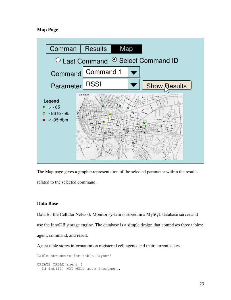
Map Page
The Map page gives a graphic representation of the selected parameter within the results
related to the selected command.
Data Base
Data for the Cellular Network Monitor system is stored in a MySQL database server and
use the InnoDB storage engine. The database is a simple design that comprises three tables:
agent, command, and result.
Agent table stores information on registered cell agents and their current states.
Table structure for table 'agent'
CREATE TABLE agent (
id int(11) NOT NULL auto_increment,
Last Command Select Command ID
Comman Results Map
Command Command 1
Parameter RSSI Show Results
> - 85
- 86 to - 95
< -95 dbm
Legend
24
number varchar(10) NOT NULL COMMENT 'mobile phone number',
`status` enum('online','offline') NOT NULL COMMENT 'known status',
PRIMARY KEY (id),
UNIQUE KEY number (number)
) ENGINE=InnoDB DEFAULT CHARSET=latin1 COMMENT='Registered cell agents';
Command table stores submitted commands and related information, such as , addressee
agents and submission time.
Table structure for table 'command'
CREATE TABLE command (
seq int(11) NOT NULL auto_increment COMMENT 'request Id',
command varchar(16) NOT NULL COMMENT 'Command sent',
due datetime NOT NULL COMMENT 'Meassuring start',
minutesinterval int(11) NOT NULL COMMENT 'repetitions interval ',
count int(11) NOT NULL COMMENT 'Number of meassures to be made',
recipient varchar(16) NOT NULL COMMENT 'Command destination address',
recipients_count int(11) NOT NULL COMMENT 'Number of recipients',
`status` enum('Sent','Fail') default NULL COMMENT 'Send status',
requesttime timestamp NOT NULL default '0000-00-00 00:00:00' on update
CURRENT_TIMESTAMP,
PRIMARY KEY (seq)
) ENGINE=InnoDB DEFAULT CHARSET=latin1;
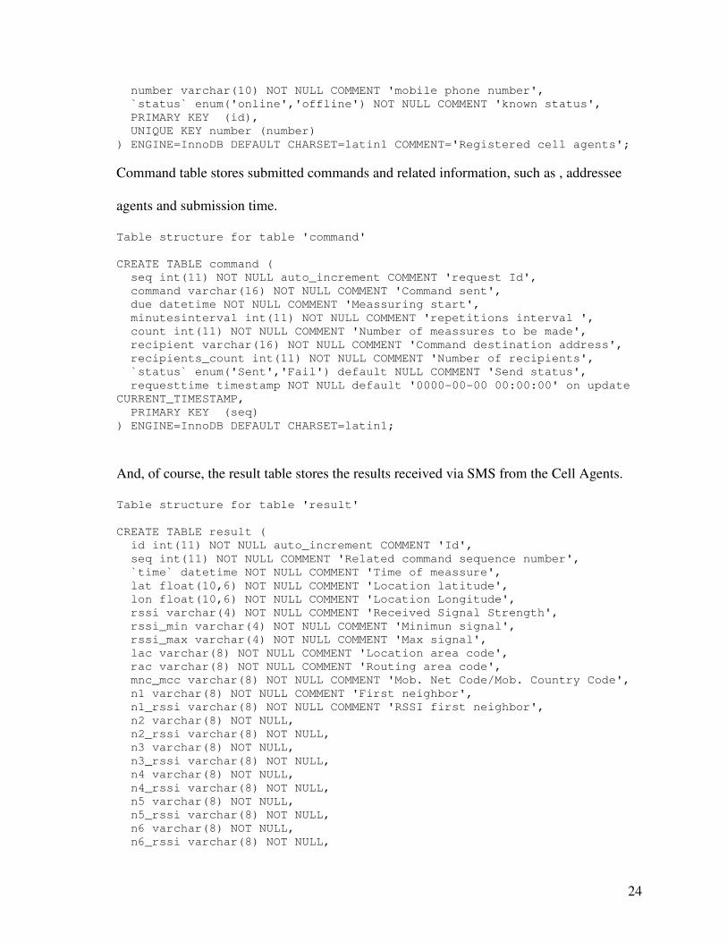
And, of course, the result table stores the results received via SMS from the Cell Agents.
Table structure for table 'result'
CREATE TABLE result (
id int(11) NOT NULL auto_increment COMMENT 'Id',
seq int(11) NOT NULL COMMENT 'Related command sequence number',
`time` datetime NOT NULL COMMENT 'Time of meassure',
lat float(10,6) NOT NULL COMMENT 'Location latitude',
lon float(10,6) NOT NULL COMMENT 'Location Longitude',
rssi varchar(4) NOT NULL COMMENT 'Received Signal Strength',
rssi_min varchar(4) NOT NULL COMMENT 'Minimun signal',
rssi_max varchar(4) NOT NULL COMMENT 'Max signal',
lac varchar(8) NOT NULL COMMENT 'Location area code',
rac varchar(8) NOT NULL COMMENT 'Routing area code',
mnc_mcc varchar(8) NOT NULL COMMENT 'Mob. Net Code/Mob. Country Code',
n1 varchar(8) NOT NULL COMMENT 'First neighbor',
n1_rssi varchar(8) NOT NULL COMMENT 'RSSI first neighbor',
n2 varchar(8) NOT NULL,
n2_rssi varchar(8) NOT NULL,
n3 varchar(8) NOT NULL,
n3_rssi varchar(8) NOT NULL,
n4 varchar(8) NOT NULL,
n4_rssi varchar(8) NOT NULL,
n5 varchar(8) NOT NULL,
n5_rssi varchar(8) NOT NULL,
n6 varchar(8) NOT NULL,
n6_rssi varchar(8) NOT NULL,
25
last_registered_mnc_mcc varchar(8) NOT NULL,
PRIMARY KEY (id),
KEY seq (seq)
) ENGINE=InnoDB DEFAULT CHARSET=latin1 COMMENT='Results from agents';
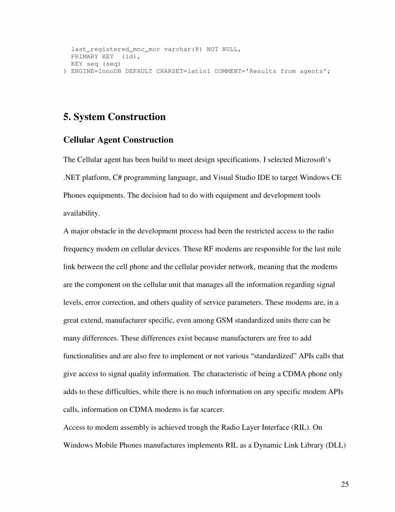
5. System Construction
Cellular Agent Construction
The Cellular agent has been build to meet design specifications. I selected Microsoft’s
.NET platform, C# programming language, and Visual Studio IDE to target Windows CE
Phones equipments. The decision had to do with equipment and development tools
availability.
A major obstacle in the development process had been the restricted access to the radio
frequency modem on cellular devices. These RF modems are responsible for the last mile
link between the cell phone and the cellular provider network, meaning that the modems
are the component on the cellular unit that manages all the information regarding signal
levels, error correction, and others quality of service parameters. These modems are, in a
great extend, manufacturer specific, even among GSM standardized units there can be
many differences. These differences exist because manufacturers are free to add
functionalities and are also free to implement or not various “standardized” APIs calls that
give access to signal quality information. The characteristic of being a CDMA phone only
adds to these difficulties, while there is no much information on any specific modem APIs
calls, information on CDMA modems is far scarcer.
Access to modem assembly is achieved trough the Radio Layer Interface (RIL). On
Windows Mobile Phones manufactures implements RIL as a Dynamic Link Library (DLL)
26
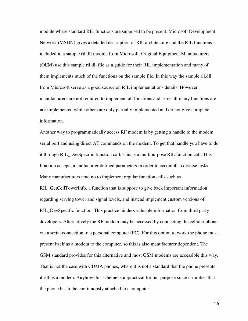
module where standard RIL functions are supposed to be present. Microsoft Development
Network (MSDN) gives a detailed description of RIL architecture and the RIL functions
included in a sample ril.dll module from Microsoft. Original Equipment Manufacturers
(OEM) use this sample ril.dll file as a guide for their RIL implementation and many of
them implements much of the functions on the sample file. In this way the sample ril.dll
from Microsoft serve as a good source on RIL implementations details. However
manufacturers are not required to implement all functions and as result many functions are
not implemented while others are only partially implemented and do not give complete
information.
Another way to programmatically access RF modem is by getting a handle to the modem
serial port and using direct AT commands on the modem. To get that handle you have to do
it through RIL_DevSpecific function call. This is a multipurpose RIL function call. This
function accepts manufacturer defined parameters in order to accomplish diverse tasks.
Many manufacturers tend no to implement regular function calls such as
RIL_GetCellTowerInfo, a function that is suppose to give back important information
regarding serving tower and signal levels, and instead implement custom versions of
RIL_DevSpecific function. This practice hinders valuable information from third party
developers. Alternatively the RF modem may be accessed by connecting the cellular phone
via a serial connection to a personal computer (PC). For this option to work the phone must
present itself as a modem to the computer, so this is also manufacturer dependent. The
GSM standard provides for this alternative and most GSM modems are accessible this way.
That is not the case with CDMA phones, where it is not a standard that the phone presents
itself as a modem. Anyhow this scheme is unpractical for our purpose since it implies that
the phone has to be continuously attached to a computer.
27
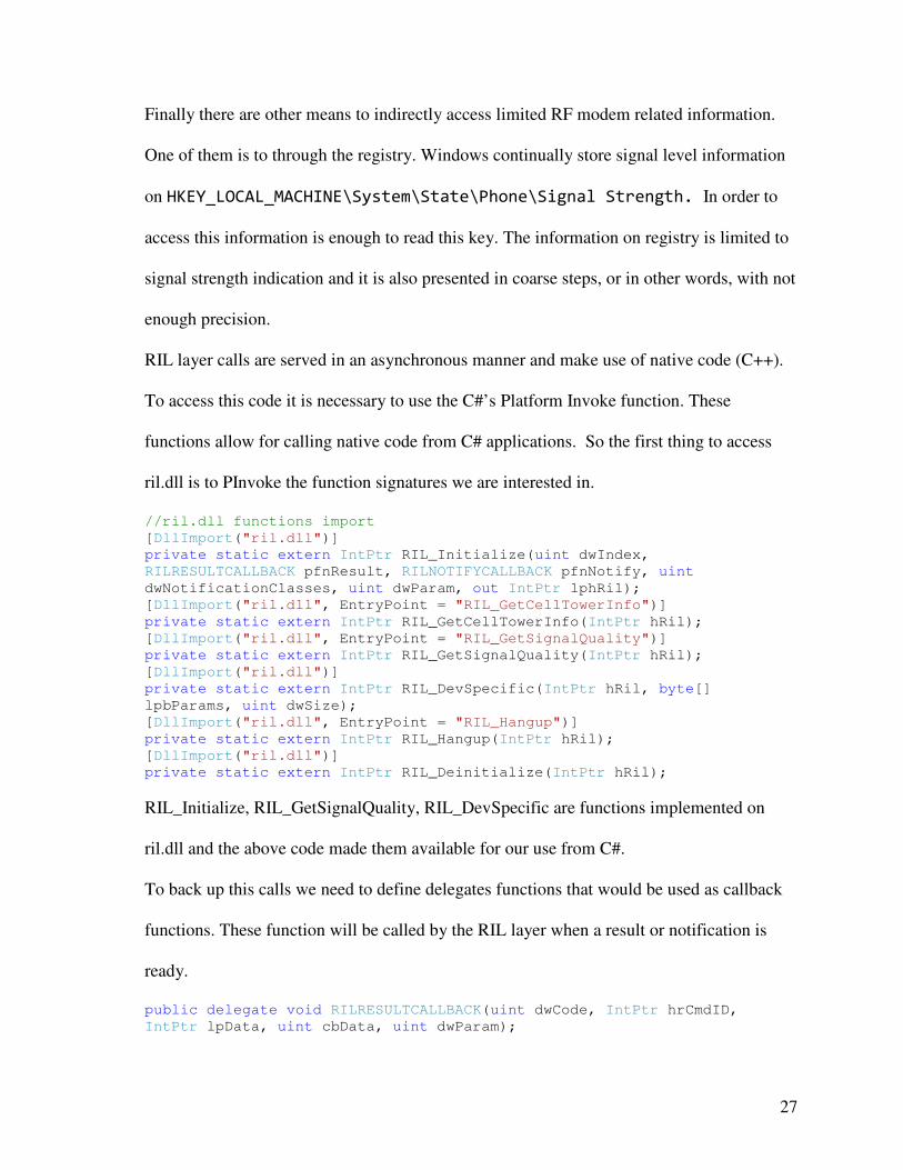
Finally there are other means to indirectly access limited RF modem related information.
One of them is to through the registry. Windows continually store signal level information
on HKEY_LOCAL_MACHINE\System\State\Phone\Signal Strength. In order to
access this information is enough to read this key. The information on registry is limited to
signal strength indication and it is also presented in coarse steps, or in other words, with not
enough precision.
RIL layer calls are served in an asynchronous manner and make use of native code (C++).
To access this code it is necessary to use the C#’s Platform Invoke function. These
functions allow for calling native code from C# applications. So the first thing to access
ril.dll is to PInvoke the function signatures we are interested in.
//ril.dll functions import
[DllImport("ril.dll")]
private static extern IntPtr RIL_Initialize(uint dwIndex,
RILRESULTCALLBACK pfnResult, RILNOTIFYCALLBACK pfnNotify, uint
dwNotificationClasses, uint dwParam, out IntPtr lphRil);
[DllImport("ril.dll", EntryPoint = "RIL_GetCellTowerInfo")]
private static extern IntPtr RIL_GetCellTowerInfo(IntPtr hRil);
[DllImport("ril.dll", EntryPoint = "RIL_GetSignalQuality")]
private static extern IntPtr RIL_GetSignalQuality(IntPtr hRil);
[DllImport("ril.dll")]
private static extern IntPtr RIL_DevSpecific(IntPtr hRil, byte[]
lpbParams, uint dwSize);
[DllImport("ril.dll", EntryPoint = "RIL_Hangup")]
private static extern IntPtr RIL_Hangup(IntPtr hRil);
[DllImport("ril.dll")]
private static extern IntPtr RIL_Deinitialize(IntPtr hRil);
RIL_Initialize, RIL_GetSignalQuality, RIL_DevSpecific are functions implemented on
ril.dll and the above code made them available for our use from C#.
To back up this calls we need to define delegates functions that would be used as callback
functions. These function will be called by the RIL layer when a result or notification is
ready.
public delegate void RILRESULTCALLBACK(uint dwCode, IntPtr hrCmdID,
IntPtr lpData, uint cbData, uint dwParam);
28
public delegate void RILNOTIFYCALLBACK(uint dwCode, IntPtr lpData, uint
cbData, uint dwParam);
RILRESULTCALLBACK and RILNOTIFYCALLBACK types describe the signature of
these functions.
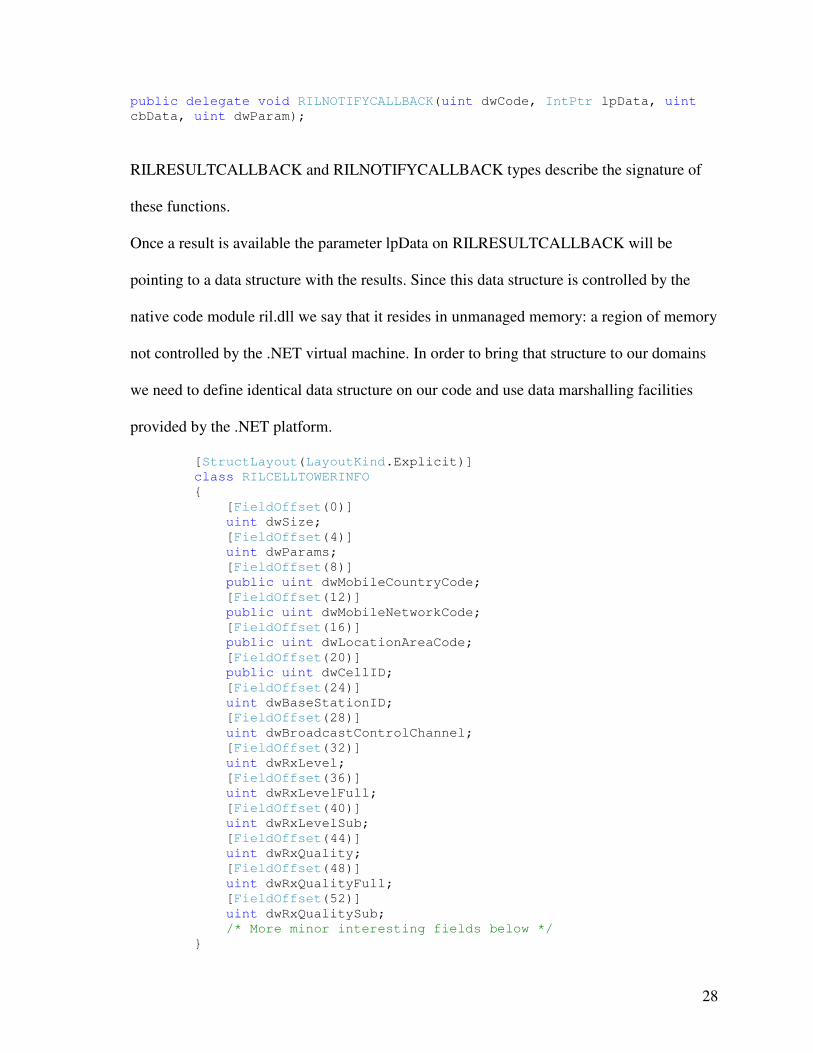
Once a result is available the parameter lpData on RILRESULTCALLBACK will be
pointing to a data structure with the results. Since this data structure is controlled by the
native code module ril.dll we say that it resides in unmanaged memory: a region of memory
not controlled by the .NET virtual machine. In order to bring that structure to our domains
we need to define identical data structure on our code and use data marshalling facilities
provided by the .NET platform.
[StructLayout(LayoutKind.Explicit)]
class RILCELLTOWERINFO
{
[FieldOffset(0)]
uint dwSize;
[FieldOffset(4)]
uint dwParams;
[FieldOffset(8)]
public uint dwMobileCountryCode;
[FieldOffset(12)]
public uint dwMobileNetworkCode;
[FieldOffset(16)]
public uint dwLocationAreaCode;
[FieldOffset(20)]
public uint dwCellID;
[FieldOffset(24)]
uint dwBaseStationID;
[FieldOffset(28)]
uint dwBroadcastControlChannel;
[FieldOffset(32)]
uint dwRxLevel;
[FieldOffset(36)]
uint dwRxLevelFull;
[FieldOffset(40)]
uint dwRxLevelSub;
[FieldOffset(44)]
uint dwRxQuality;
[FieldOffset(48)]
uint dwRxQualityFull;
[FieldOffset(52)]
uint dwRxQualitySub;
/* More minor interesting fields below */
}
29
[StructLayout(LayoutKind.Explicit)]
class RILSIGNALQUALITY
{
[FieldOffset(0)]
int dwSize;
[FieldOffset(4)]
int dwParams;
[FieldOffset(8)]
public int nSignalStrength;
[FieldOffset(12)]
public int nMinSignalStrength;
[FieldOffset(16)]
public int nMaxSignalStrength;
[FieldOffset(20)]
public uint dwBitErrorRate;
[FieldOffset(24)]
int nLowSignalStrength;
[FieldOffset(28)]
int nHighSignalStrength;
}
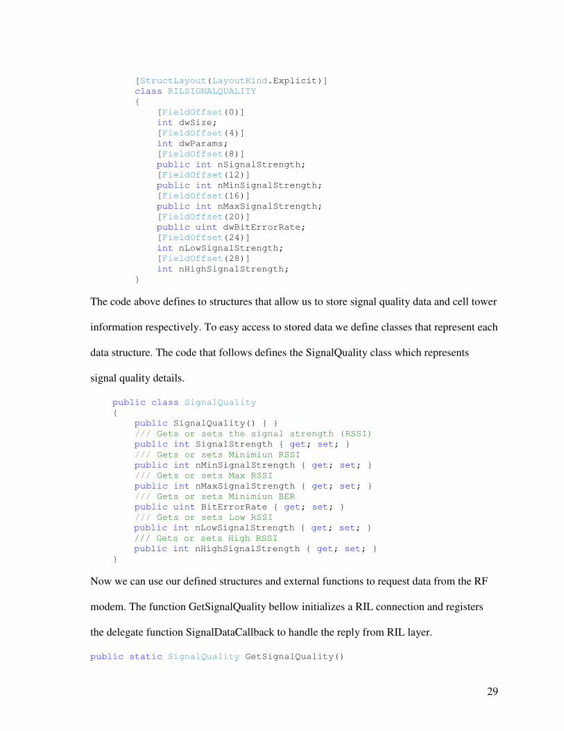
The code above defines to structures that allow us to store signal quality data and cell tower
information respectively. To easy access to stored data we define classes that represent each
data structure. The code that follows defines the SignalQuality class which represents
signal quality details.
public class SignalQuality
{
public SignalQuality() { }
/// Gets or sets the signal strength (RSSI)
public int SignalStrength { get; set; }
/// Gets or sets Minimiun RSSI
public int nMinSignalStrength { get; set; }
/// Gets or sets Max RSSI
public int nMaxSignalStrength { get; set; }
/// Gets or sets Minimiun BER
public uint BitErrorRate { get; set; }
/// Gets or sets Low RSSI
public int nLowSignalStrength { get; set; }
/// Gets or sets High RSSI
public int nHighSignalStrength { get; set; }
}
Now we can use our defined structures and external functions to request data from the RF
modem. The function GetSignalQuality bellow initializes a RIL connection and registers
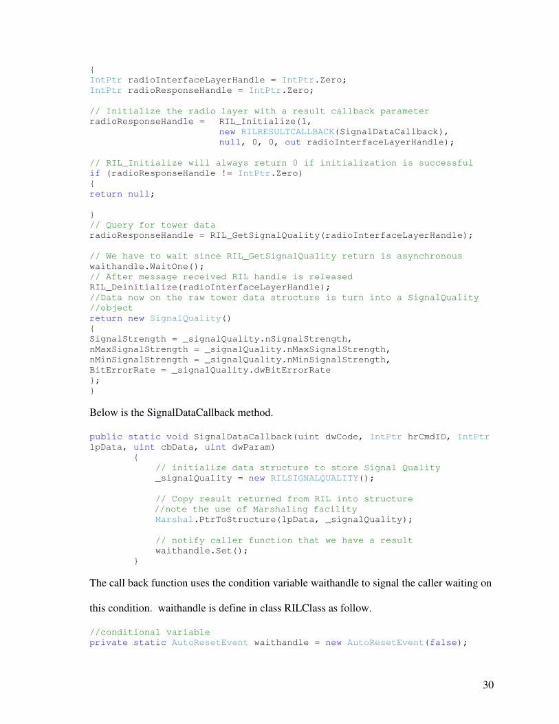
the delegate function SignalDataCallback to handle the reply from RIL layer.
public static SignalQuality GetSignalQuality()
30
{
IntPtr radioInterfaceLayerHandle = IntPtr.Zero;
IntPtr radioResponseHandle = IntPtr.Zero;
// Initialize the radio layer with a result callback parameter
radioResponseHandle = RIL_Initialize(1,
new RILRESULTCALLBACK(SignalDataCallback),
null, 0, 0, out radioInterfaceLayerHandle);
// RIL_Initialize will always return 0 if initialization is successful
if (radioResponseHandle != IntPtr.Zero)
{
return null;
}
// Query for tower data
radioResponseHandle = RIL_GetSignalQuality(radioInterfaceLayerHandle);
// We have to wait since RIL_GetSignalQuality return is asynchronous
waithandle.WaitOne();
// After message received RIL handle is released
RIL_Deinitialize(radioInterfaceLayerHandle);
//Data now on the raw tower data structure is turn into a SignalQuality
//object
return new SignalQuality()
{
SignalStrength = _signalQuality.nSignalStrength,
nMaxSignalStrength = _signalQuality.nMaxSignalStrength,
nMinSignalStrength = _signalQuality.nMinSignalStrength,
BitErrorRate = _signalQuality.dwBitErrorRate
};
}
Below is the SignalDataCallback method.
public static void SignalDataCallback(uint dwCode, IntPtr hrCmdID, IntPtr
lpData, uint cbData, uint dwParam)
{
// initialize data structure to store Signal Quality
_signalQuality = new RILSIGNALQUALITY();
// Copy result returned from RIL into structure
//note the use of Marshaling facility
Marshal.PtrToStructure(lpData, _signalQuality);
// notify caller function that we have a result
waithandle.Set();
}
The call back function uses the condition variable waithandle to signal the caller waiting on
this condition. waithandle is define in class RILClass as follow.
//conditional variable
private static AutoResetEvent waithandle = new AutoResetEvent(false);
31
The above describe code is part of the core of the Cell Agent module in the sense that is the
part intended to capture the actual measurements.
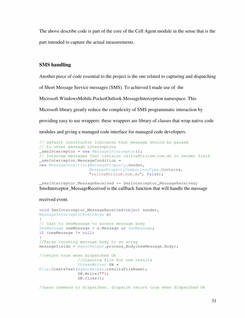
SMS handling
Another piece of code essential to the project is the one related to capturing and dispatching
of Short Message Service messages (SMS). To achieved I made use of the
Microsoft.WindowsMobile.PocketOutlook.MessageInterception namespace. This
Microsoft library greatly reduce the complexity of SMS programmatic interaction by
providing easy to use wrappers: these wrappers are library of classes that wrap native code
modules and giving a managed code interface for managed code developers.
// Default constructor indicates that message should be passed
// to other message interceptors
_smsInterceptor = new MessageInterceptor();
// Intercep messages that contains [email protected] in sender field
_smsInterceptor.MessageCondition =
new MessageCondition(MessageProperty.Sender,
MessagePropertyComparisonType.Contains,
"[email protected]", false);
_smsInterceptor.MessageReceived += SmsInterceptor_MessageReceived;
SmsInterceptor_MessageReceived is the callback function that will handle the message
received event.
void SmsInterceptor_MessageReceived(object sender,
MessageInterceptorEventArgs e)
{
// Cast to SmsMessage to access message body
SmsMessage newMessage = e.Message as SmsMessage;
if (newMessage != null)
{
//Parse incoming message body to an array
messagefields = AgentHelper.process_Body(newMessage.Body);
//return true when dispatched Ok
//cleaning file for new results
StreamWriter SW =
File.CreateText(AgentHelper.resultsFileName);
SW.Write("");
SW.Close();
//pass command to dispatcher. dispatch return true when dispatched Ok
32
//messagefields[0] is discarted, message:
//"%^#&,seq,command,due,iterval, count"
if (AgentHelper.dispatch(messagefields[1], messagefields[2],
messagefields[3], messagefields[4], messagefields[5], this))
}
}
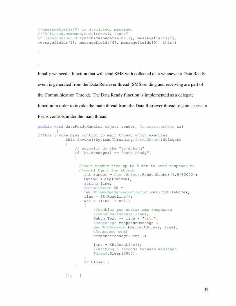
Finally we need a function that will send SMS with collected data whenever a Data Ready
event is generated from the Data Retriever thread (SMS sending and receiving are part of
the Communication Thread). The Data Ready function is implemented as a delegate
function in order to invoke the main thread from the Data Retriever thread to gain access to
forms controls under the main thread.
public void dataReadyHandler(object sender, InterpreterArgs ca)
{
//This invoke pass control to main thread which executes
this.Invoke((System.Threading.ThreadStart)delegate
{
// actually do the "something"
if (ca.Message() == "Data Ready")
{
//wait random time up to 5 min to send response to
//avoid Agent Sms attack
int random = AgentHelper.RandomNumber(1,5*60000);
Thread.Sleep(random);
string line;
StreamReader SR =
new StreamReader(AgentHelper.resultsFileName);
line = SR.ReadLine();
while (line != null)
{
//cambiar por enviar sms respuesta
//sendSmsResponse(line);
Debug.Text += line + "\r\n";
SmsMessage responseMessage =
new SmsMessage (serverAddress, line);
//meassage send
responseMessage.Send();
line = SR.ReadLine();
//waiting 5 seconds between messages
Thread.Sleep(5000);
}
SR.Close();
}
}); }
33
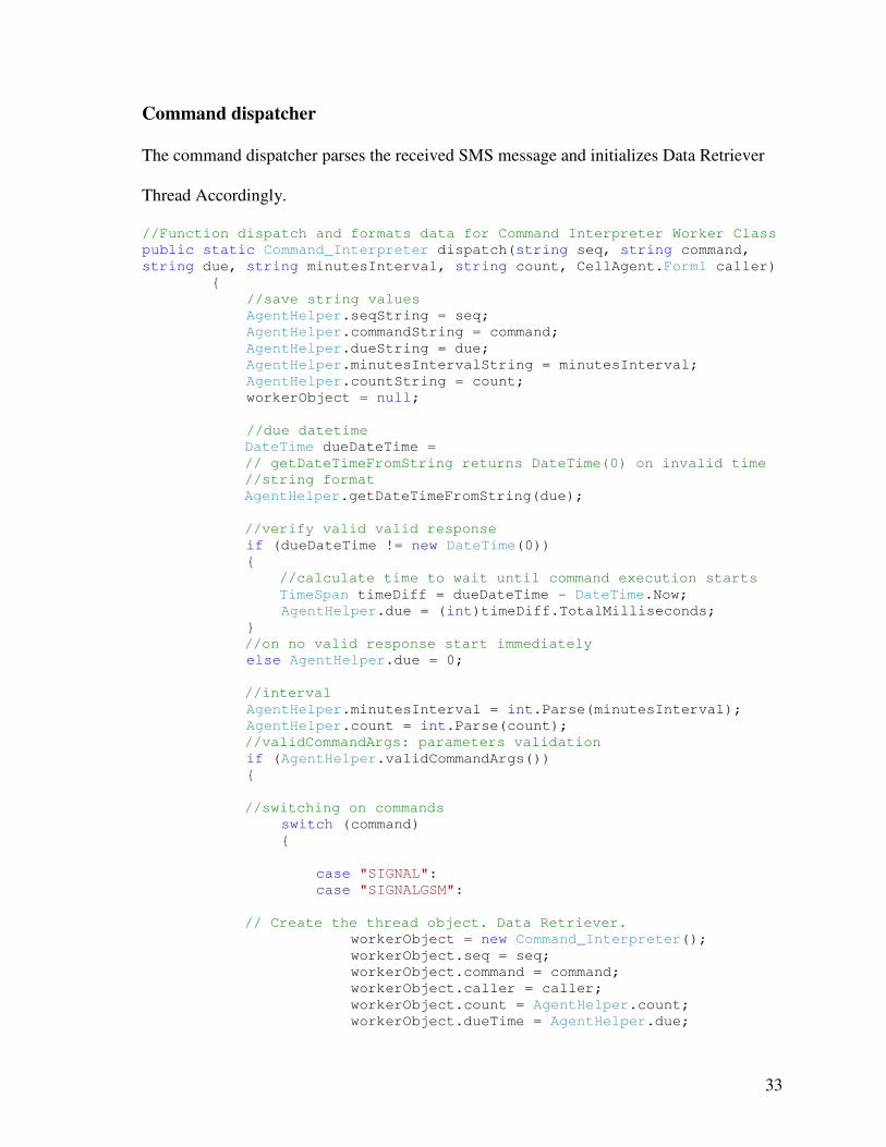
Command dispatcher
The command dispatcher parses the received SMS message and initializes Data Retriever
Thread Accordingly.
//Function dispatch and formats data for Command Interpreter Worker Class
public static Command_Interpreter dispatch(string seq, string command,
string due, string minutesInterval, string count, CellAgent.Form1 caller)
{
//save string values
AgentHelper.seqString = seq;
AgentHelper.commandString = command;
AgentHelper.dueString = due;
AgentHelper.minutesIntervalString = minutesInterval;
AgentHelper.countString = count;
workerObject = null;
//due datetime
DateTime dueDateTime =
// getDateTimeFromString returns DateTime(0) on invalid time
//string format
AgentHelper.getDateTimeFromString(due);
//verify valid valid response
if (dueDateTime != new DateTime(0))
{
//calculate time to wait until command execution starts
TimeSpan timeDiff = dueDateTime - DateTime.Now;
AgentHelper.due = (int)timeDiff.TotalMilliseconds;
}
//on no valid response start immediately
else AgentHelper.due = 0;
//interval
AgentHelper.minutesInterval = int.Parse(minutesInterval);
AgentHelper.count = int.Parse(count);
//validCommandArgs: parameters validation
if (AgentHelper.validCommandArgs())
{
//switching on commands
switch (command)
{
case "SIGNAL":
case "SIGNALGSM":
// Create the thread object. Data Retriever.
workerObject = new Command_Interpreter();
workerObject.seq = seq;
workerObject.command = command;
workerObject.caller = caller;
workerObject.count = AgentHelper.count;
workerObject.dueTime = AgentHelper.due;
34
workerObject.intTime = AgentHelper.minutesInterval * 60000;
workerObject.ResultReady += new
Command_Interpreter.ResultHandler(caller.dataReadyHandler);
Thread workerThread = new Thread(workerObject.DoWork);
// Start the Data Retriever thread.
workerThread.Start();
// Put the main thread to sleep for 1 millisecond to
// allow the worker thread to do some work:
Thread.Sleep(1);
break;
case "ABORT":
break;
default:
break;
}
//Returns Command_Interpreter object to allow stoping via RequestStop
method
return workerObject;
}
else
return null;
}
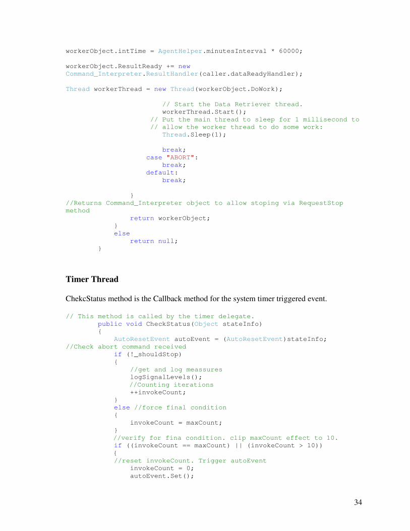
Timer Thread
ChekcStatus method is the Callback method for the system timer triggered event. // This method is called by the timer delegate.
public void CheckStatus(Object stateInfo)
{
AutoResetEvent autoEvent = (AutoResetEvent)stateInfo;
//Check abort command received
if (!_shouldStop)
{
//get and log meassures
logSignalLevels();
//Counting iterations
++invokeCount;
}
else //force final condition
{
invokeCount = maxCount;
}
//verify for fina condition. clip maxCount effect to 10.
if ((invokeCount == maxCount) || (invokeCount > 10))
{
//reset invokeCount. Trigger autoEvent
invokeCount = 0;
autoEvent.Set();
35
}}
Server Construction
The Cellular Network Monitor server side components run on an Apache – MySQL – PHP
server with the following characteristics:
Apache version: Apache/2.2.4 (Win32)
MySQL version: 5.0.27-community-nt-log
PHP version: 5.2.1
PHP loaded extensions
bcmath, calendar, com_dotnet, ctype, session, filter, ftp, hash, iconv, json, odbc, pcre,
Reflection, date, libxml, standard, tokenizer, zlib, SimpleXML, dom, SPL, wddx, xml,
xmlreader, xmlwriter, apache2handler, mbstring, gd, imap, mysql, mysqli, PDO,
pdo_sqlite, SQLite
Cell Server Application
The Cell Server Application consists of a group of PHP scripts that serve the interactions
between the Cell Agents on costumer’s cell phones, the system’s database, and system’s
users.
SMS Handling – Sending
Communication from users to cell agents is handled by the sendCommand.php component.
This script formats messages to be sent to cell agents, sends the message to all recipients
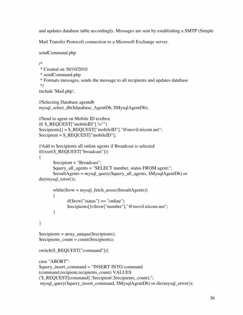
36
and updates database table accordingly. Messages are sent by establishing a SMTP (Simple
Mail Transfer Protocol) connection to a Microsoft Exchange server.
sendCommand.php
/* * Created on 30/10/2010 * sendCommand.php * Formats messages, sends the message to all recipients and updates database */ include 'Mail.php'; //Selecting Database agentdb mysql_select_db($database_AgentDb, $MysqlAgentDb); //Send to agent on Mobile ID textbox if( $_REQUEST["mobileID"] !="") $recipients[] = $_REQUEST["mobileID"]."@movil.tricom.net"; $recipient = $_REQUEST["mobileID"]; //Add to $recipients all online agents if Broadcast is selected if(isset($_REQUEST["broadcast"])) { $recipient = "Broadcast"; $query_all_agents = "SELECT number, status FROM agent;"; $resultAgents = mysql_query($query_all_agents, $MysqlAgentDb) or die(mysql_error()); while($row = mysql_fetch_assoc($resultAgents)) { if($row["status"] == "online") $recipients[]=$row["number"]."@movil.tricom.net"; } } $recipients = array_unique($recipients); $recipients_count = count($recipients); switch($_REQUEST["command"]){ case "ABORT": $query_insert_command = "INSERT INTO command (command,recipient,recipients_count) VALUES ('$_REQUEST[command]','$recipient',$recipients_count);"; mysql_query($query_insert_command, $MysqlAgentDb) or die(mysql_error());

37
$seq = mysql_insert_id($MysqlAgentDb); $msg = ",$seq,$_REQUEST[command],$_REQUEST[due],$_REQUEST[minutesinterval],$_REQUEST[count],"; if (sendSms($recipients,$msg)) { $query_insert_command = "UPDATE command SET status='Sent' WHERE seq=$seq;"; mysql_query($query_insert_command, $MysqlAgentDb) or die(mysql_error()); } else { $query_insert_command = "UPDATE command SET status='Fail' WHERE seq=$seq;"; mysql_query($query_insert_command, $MysqlAgentDb) or die(mysql_error()); } break; default: $query_insert_command = "INSERT INTO command (command,due,minutesinterval,count,recipient,recipients_count) VALUES ('$_REQUEST[command]','$_REQUEST[due]',$_REQUEST[minutesinterval],$_REQUEST[count],'$recipient',$recipients_count);"; mysql_query($query_insert_command, $MysqlAgentDb) or die(mysql_error()); $seq = mysql_insert_id($MysqlAgentDb); echo $msg = ",$seq,$_REQUEST[command],$_REQUEST[due],$_REQUEST[minutesinterval],$_REQUEST[count],"; if (sendSms($recipients,$msg)) { $query_insert_command = "UPDATE command SET status='Sent' WHERE seq=$seq;"; mysql_query($query_insert_command, $MysqlAgentDb) or die(mysql_error()); } else { $query_insert_command = "UPDATE command SET status='Fail' WHERE seq=$seq;"; mysql_query($query_insert_command, $MysqlAgentDb) or die(mysql_error()); } break; } function sendSms($agentsAddArray,$msg){ /* mail setup recipients, subject etc */ $recipients = $agentsAddArray; $headers["From"] = "[email protected]";
38
//$headers["To"] = $agentsAddArray; $headers["Subject"] = "Prueba"; $mailmsg = $msg; $smtpinfo["host"] = "tricom.com.do"; $smtpinfo["port"] = "25"; $smtpinfo["auth"] = "LOGIN"; $smtpinfo["username"] = "Victor Silva"; $smtpinfo["password"] = $_SESSION['mailpass']; /* Create the mail object using the Mail::factory method */ $mail_object =& Mail::factory("smtp", $smtpinfo); /* Ok send mail */ $send=$mail_object->send($recipients, $headers, $mailmsg); if (PEAR::isError($send)) { print($send->getMessage()); return false; } return true; } ?>
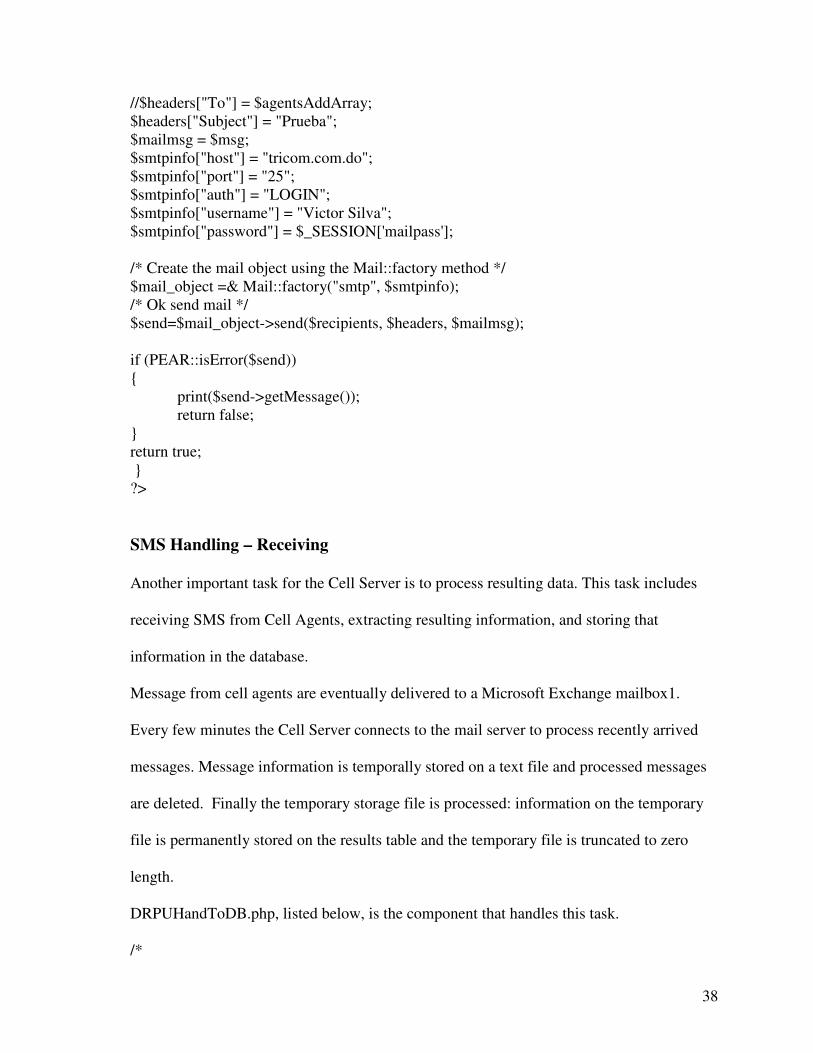
SMS Handling – Receiving
Another important task for the Cell Server is to process resulting data. This task includes
receiving SMS from Cell Agents, extracting resulting information, and storing that
information in the database.
Message from cell agents are eventually delivered to a Microsoft Exchange mailbox1.
Every few minutes the Cell Server connects to the mail server to process recently arrived
messages. Message information is temporally stored on a text file and processed messages
are deleted. Finally the temporary storage file is processed: information on the temporary
file is permanently stored on the results table and the temporary file is truncated to zero
length.
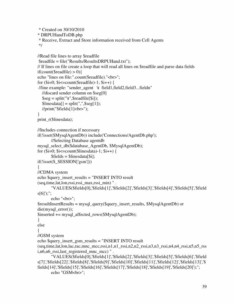
DRPUHandToDB.php, listed below, is the component that handles this task. /*
39
* Created on 30/10/2010 * DRPUHandToDB.php * Receive, Extract and Store information received from Cell Agents */ //Read file lines to array $readfile $readfile = file("Results/ResultsDRPUHand.txt"); // If lines on file create a loop that will read all lines on $readfile and parse data fields if(count($readfile) > 0){ echo "lines on file:".count($readfile)."<br>"; for ($i=0; $i<=count($readfile)-1; $i++) { //line example: "sender_agent \t field1,field2,field3...fieldn" //discard sender column on $seg[0] $seg = split("\t",$readfile[$i]); $linesdata[] = split(",",$seg[1]); //print("$fields[1]<br>"); } print_r($linesdata); //Includes connection if necessary if(!isset($MysqlAgentDb)) include('Connections/AgentDb.php'); //Selecting Database agentdb mysql_select_db($database_AgentDb, $MysqlAgentDb); for ($i=0; $i<=count($linesdata)-1; $i++) { $fields = $linesdata[$i]; if(!isset($_SESSION['gsm'])) { //CDMA system echo $query_insert_results = "INSERT INTO result (seq,time,lat,lon,rssi,rssi_max,rssi_min) " . "VALUES($fields[0],'$fields[1]','$fields[2]','$fields[3]','$fields[4]','$fields[5]','$fields[6]');"; echo "<br>"; $resultInsertResults = mysql_query($query_insert_results, $MysqlAgentDb) or die(mysql_error()); $inserted += mysql_affected_rows($MysqlAgentDb); } else { //GSM system echo $query_insert_gsm_results = "INSERT INTO result (seq,time,lat,lon,lac,rac,mnc_mcc,rssi,n1,n1_rssi,n2,n2_rssi,n3,n3_rssi,n4,n4_rssi,n5,n5_rssi,n6,n6_rssi,last_registered_mnc_mcc) " . "VALUES($fields[0],'$fields[1]','$fields[2]','$fields[3]','$fields[5]','$fields[6]','$fields[7]','$fields[22]','$fields[8]','$fields[9]','$fields[10]','$fields[11]','$fields[12]','$fields[13]','$fields[14]','$fields[15]','$fields[16]','$fields[17]','$fields[18]','$fields[19]','$fields[20]');"; echo "GSM<br>";
40
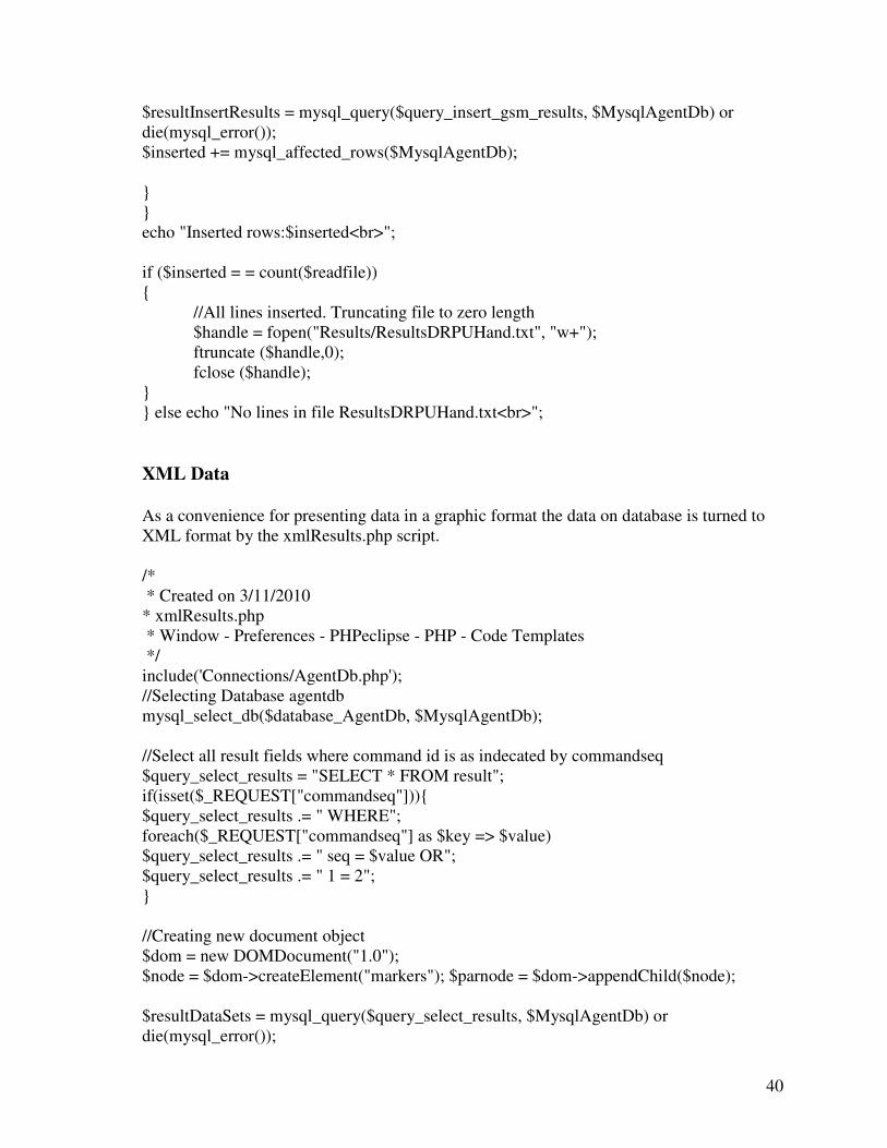
$resultInsertResults = mysql_query($query_insert_gsm_results, $MysqlAgentDb) or die(mysql_error()); $inserted += mysql_affected_rows($MysqlAgentDb); } } echo "Inserted rows:$inserted<br>"; if ($inserted = = count($readfile)) { //All lines inserted. Truncating file to zero length $handle = fopen("Results/ResultsDRPUHand.txt", "w+"); ftruncate ($handle,0); fclose ($handle); } } else echo "No lines in file ResultsDRPUHand.txt<br>";
XML Data
As a convenience for presenting data in a graphic format the data on database is turned to XML format by the xmlResults.php script. /* * Created on 3/11/2010 * xmlResults.php * Window - Preferences - PHPeclipse - PHP - Code Templates */ include('Connections/AgentDb.php'); //Selecting Database agentdb mysql_select_db($database_AgentDb, $MysqlAgentDb); //Select all result fields where command id is as indecated by commandseq $query_select_results = "SELECT * FROM result"; if(isset($_REQUEST["commandseq"])){ $query_select_results .= " WHERE"; foreach($_REQUEST["commandseq"] as $key => $value) $query_select_results .= " seq = $value OR"; $query_select_results .= " 1 = 2"; } //Creating new document object $dom = new DOMDocument("1.0"); $node = $dom->createElement("markers"); $parnode = $dom->appendChild($node); $resultDataSets = mysql_query($query_select_results, $MysqlAgentDb) or die(mysql_error());
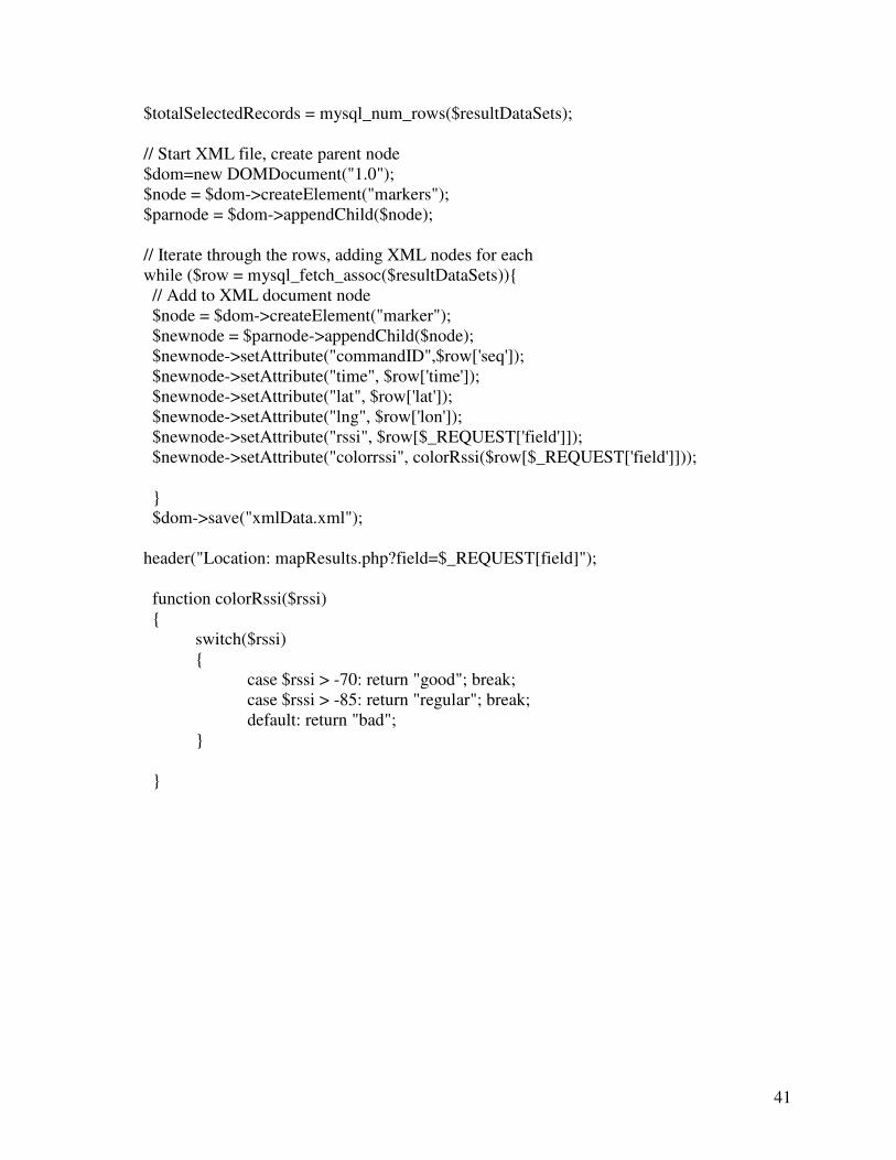
41
$totalSelectedRecords = mysql_num_rows($resultDataSets); // Start XML file, create parent node $dom=new DOMDocument("1.0"); $node = $dom->createElement("markers"); $parnode = $dom->appendChild($node); // Iterate through the rows, adding XML nodes for each while ($row = mysql_fetch_assoc($resultDataSets)){ // Add to XML document node $node = $dom->createElement("marker"); $newnode = $parnode->appendChild($node); $newnode->setAttribute("commandID",$row['seq']); $newnode->setAttribute("time", $row['time']); $newnode->setAttribute("lat", $row['lat']); $newnode->setAttribute("lng", $row['lon']); $newnode->setAttribute("rssi", $row[$_REQUEST['field']]); $newnode->setAttribute("colorrssi", colorRssi($row[$_REQUEST['field']])); } $dom->save("xmlData.xml"); header("Location: mapResults.php?field=$_REQUEST[field]"); function colorRssi($rssi) { switch($rssi) { case $rssi > -70: return "good"; break; case $rssi > -85: return "regular"; break; default: return "bad"; } }
42
6. Conclusions
At this point we can state that the developed tool meets the requirements and serve as
concept prove of the viability to build a cellular network monitoring system relying on
subscriber units. The main requirement of having a tool to ease and speed up field data
collection was reasonably achieved.
On the building process of the Cellular Network Monitor tool we found several obstacles,
being the most challenging the difficulties to get the required information out of the radio
frequency modem equipment that sits on each cell phone. In a real product development
scenario these impediments should be easily overcome: a cellular service provider may be
able to obtain the required information, permissions, and development tools from Original
Equipment Manufactures to address those issues.
A pending point is that the system lacks of a clean communication path from agents back to
the server, this pitfall oblige the user to perform a manual step to get received messages
from mobile agents to the database. This can be overcome by implementing a software
patch on the service provider’s SMS gateway.
Other useful features can be added to the CNM tool. An example could be the ability of cell
agents to report call details and position coordinates when some defined events, such as
dropped calls, are detected. The addition of this and others features can be the object of
future works on this matter.
43
7. References
1. David Soldani, Means and Methods for Collecting and Analyzing QoE Measurements in
Wireless Networks, Proceedings of the 2006 International Symposium on a World of
Wireless, Mobile and Multimedia Networks (WoWMoM'06),
[email protected], 2006.
2. Hailiang Mei, Johan Lukkien, A Remote Personal Device Management Framework
Based on SyncML DM Specifications, 2005.
3. SyncML White Paper, Building an Industry-Wide Mobile Data Synchronization
Protocol, 2000.
4. Stefano Fornari, Developing Mobile J2METM Applications With Sync4j and
SyncML, 2005.
5. Dreamtech Software Team, Wireless Programming with J2ME: Cracking the Code,
2002.
6. MSDN (Microsoft Developer Network) Library, RIL Reference, 2010.
http://msdn.microsoft.com/en-us/library/aa920441.aspx