Embed Size (px)
Citation preview

Cellular Systems and Infrastructure-Based Wireless Networks
ABSTRACT
Infrastructure-based wireless networks have base stations (access points).Advantages over Ad-hoc networks :
- efficiently utilize network resources.- single-hop routes, results in :- lower delay and loss- higher data ratesExamples : Wireless LANs, paging systems, and
cellular phone systems.

References
[1] Andrea Goldsmith, "Wireless Communications", Cambridge University Press, 2005.
[2] David Tse; Pramod Viswanath, "Fundamentals of Wireless Communication", Cambridge University Press, 2004.
[3] Simon Haykin, "Communication Systems", John Willy & sons, 2001.
[4] William Stallings, "Data and Computer Communications", Pearson Education, 2004.
[5] Lucent Technologies; Bell Labs Innovations, "GSM Introduction WL9001", 1998.

OUTLINECellular System Fundamentals
Reuse Distance Ddiamond-shaped CellsHexagonally-shaped cells
SINR & User Capacity
Interference Reduction Techniques
Dynamic Resource AllocationSchedulingDCAPower Control Fundamental Rate limitsShannon’s CapacityArea Spectral EfficiencyCase Study
Cellular System Fundamentals:Channel Reuse
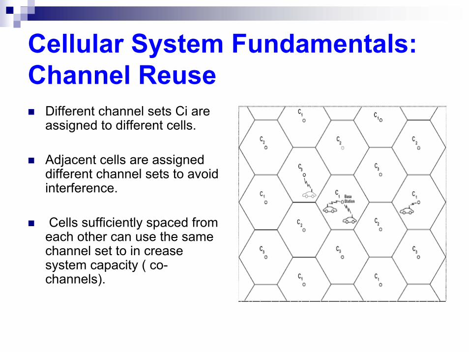
Different channel sets Ci are assigned to different cells.
Adjacent cells are assigned different channel sets to avoid interference.
Cells sufficiently spaced from each other can use the same channel set to in crease system capacity ( co-channels).

Cellular System Fundamentals:Handover
is the process of automatically switching a call in progress from one traffic channel to another to neutralize the adverse effects of user movements [5]
Cellular System Fundamentals:Access Techniques
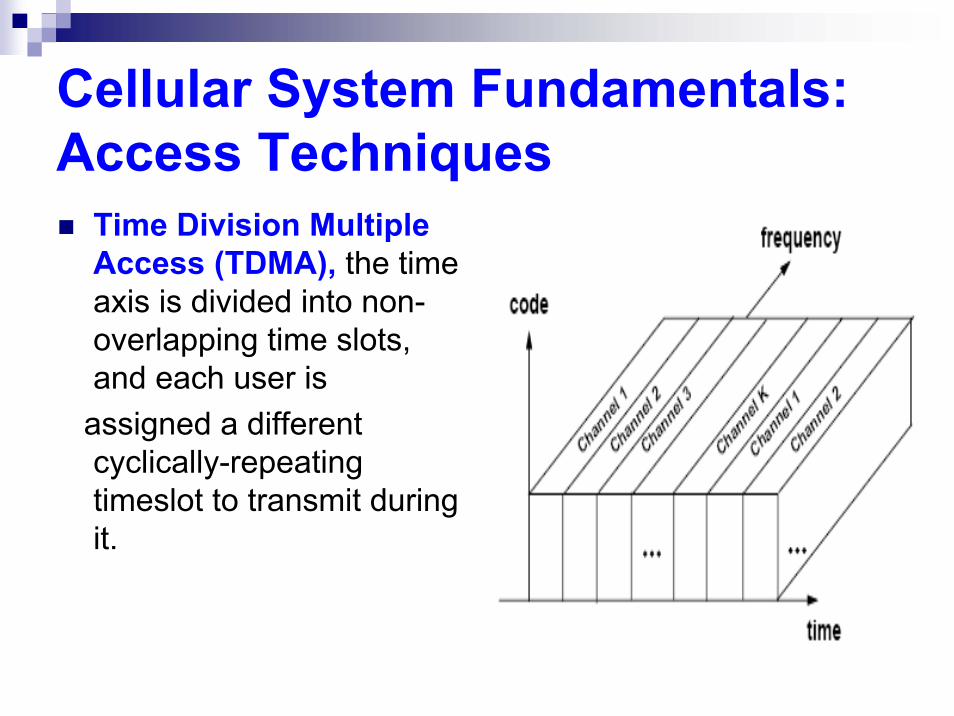
Time Division Multiple Access (TDMA), the time axis is divided into non-overlapping time slots, and each user is
assigned a different cyclically-repeating timeslot to transmit during it.
Cellular System Fundamentals:Access Techniques
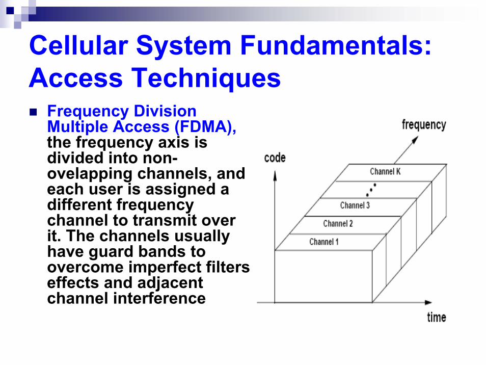
Frequency Division Multiple Access (FDMA), the frequency axis is divided into non-ovelapping channels, and each user is assigned a different frequency channel to transmit over it. The channels usually have guard bands to overcome imperfect filters effects and adjacent channel interference

Cellular System Fundamentals:Access Techniques
Code Division Multiple Access (CDMA),information of different users are modulated by orthogonal or non-orthogonal spreading codes. The resulting spread signals simultaneously occupy the same time and bandwidth.
Cellular System Fundamentals:Access Techniques
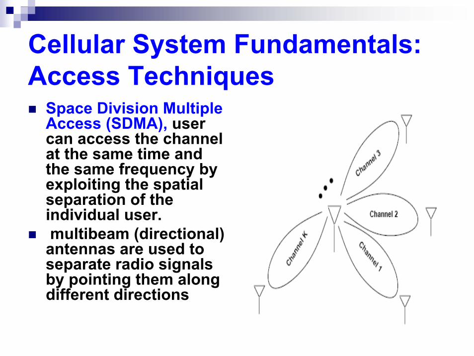
Space Division Multiple Access (SDMA), user can access the channel at the same time and the same frequency by exploiting the spatial separation of the individual user. multibeam (directional) antennas are used to separate radio signals by pointing them along different directions
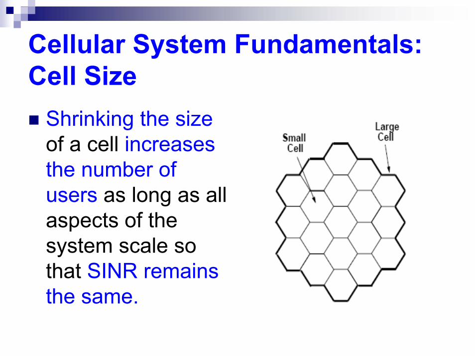
Cellular System Fundamentals:Cell Size
Shrinking the sizeof a cell increases the number of users as long as all aspects of the system scale so that SINR remains the same.

Cellular System Fundamentals:Cell Shape
Cellular System Fundamentals:Reuse Distance D
the distance between the centers of cells that use the same channels.
is a function of cell shape, cell size, and the number of intermediate cells between the two cells sharing the same channel.

Cellular System Fundamentals:Reuse Distance D
For Diamond-shaped cells;
D = R + 2RNI + R= 2R (NI + 1)
NI, no, of intermediate cells any two between co-channel cells.

Cellular System Fundamentals:Reuse Distance D
For hexagonally-shaped cells;
E. g. cell G is located at (0, 1), cell S is located at (1, 1), cell P is located at (−2, 2), and cell M is located at (−1,−1).

Cellular System Fundamentals:Cell Clustering
For diamond-shaped cellsa tesselating cell cluster forms another diamond, with K cells on each side (K = 4 in fig.)The number of cells per cluster is N = K², which is also called the reuse factor: since D = 2KR, we have N = .25(D/R),

Cellular System Fundamentals:Cell Clustering
For hexagonally-shaped cells:total BW is broken into N channel sets C1,..., CN, ,N =cluster sizeStrating from origin, assign channels as shown (move i cells and then move j cellsThen start from another arbitrary cell, and so on until cells assigned channels.

Cellular System Fundamentals:Cell Clustering

SINR & User CapacitySINR
Orthogonal Channelization (TDMA & FDMA):Intercell Interfernce (Co-channel interference)
Non-Orthogonal Channelization (CDMA):Intercell Interference + intracell Interfernce

SINR & User CapacitySINR
Pr is the received signal power, PI is the received power associated with both intracell and intercell interference, and N0B is noise power.

SINR & User CapacitySIR
Good cellular system designs are interference-limited [1]i. e. PI >> N0B
N0B ≈ zero
SIR = Pr / PI

SINR & User Capacityexample: SIR (Uplink TDMA)
the simplified path loss model
d=propagation distance; K is a unitless constant depends on antenna characteristics and average channel attenuation, do is a reference distance for the antenna far-field, and γ is the path loss exponent, the value of γ depends on the propagation environment: for free-space model 2 ≤ γ ≤ 4
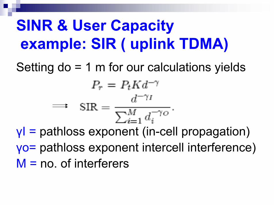
SINR & User Capacityexample: SIR ( uplink TDMA)
Setting do = 1 m for our calculations yields
γI = pathloss exponent (in-cell propagation)γo= pathloss exponent intercell interference)M = no. of interferers
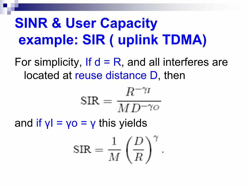
SINR & User Capacityexample: SIR ( uplink TDMA)
For simplicity, If d = R, and all interferes are located at reuse distance D, then
and if γI = γo = γ this yields

SINR & User CapacityUser Capacity (Cu)The user capacity Cu is defined as the total number of active users per cell that the system can support while meeting a common BER constraint for all users [1].
the user capacity Cu = Nc,N c = No. of channels assigned to any given cell.

SINR & User CapacityUser Capacity (Cu)For orthogonal multiple access,
B=BWBs= channel BWNT= total No. Of orthogonal ChannelsN=reuse factorG=Ratio of total BW to individual user BW

Interference Reduction Techniques
Multipath can cause fading due to phase cancellation between different propagation paths which reduce signal power against noise.Delay Spread results from differences in propagation delays among multiple propagation delay, this delay spread can lead to a significant intersymbol interference in the received signal.Co-channel interference.

Interference Reduction TechniquesAntenna Sectorization
directional antennas to divide up a base station's 360 omnidirectional antenna to N sectorsinterference to a given mobile comes primarily from its sectorreducing interference power by roughly a factor of N

Interference Reduction TechniquesSmart Antennas
consists of an antenna array combined with signal processing in both time and space. form narrow beams to provide high gain to the desired user's signal and can provide spatial nulls in the direction of interference
Interference Reduction Techniquesother techniques
Interference Averaging.
Multiuser Detection.
Interference Precancellation.

Dynamic Resource Allocation
Cellular systems are dynamic in the number of users in any given cell and in their time-varying channel gains.As voice applications are migrated with Multimedia data, user no longer have uniform data rate requirements.

Dynamic Resource Allocation
a flexible resource allocation is required to dynamically assign
channels, data rates, and power levels
relative to the current system conditions and user needs.
Dynamic Resource AllocationScheduling
dynamically allocate resources to mobile users according to their required data rates and delay constraints. exploits multiuser diversity to allocate resources to the user with the best channel.unfair to users with inferior channels.

Dynamic Resource AllocationDynamic Channel Allocation
Falls into two categories,Dynamic assignment of multiple channels within a cell (intracell DCA).Assignment of channels between cells (intercell DCA) for orthogonal channelization.
Dynamic Resource AllocationDynamic Channel AllocationIntracell DCA allows dynamic assignment
of multiple channels within a cell to a given user. In TDMA systems this is done by assigning a user multiple timeslots, and in CDMA by assigning a user multiple codes and/or spreading factors.
Dynamic Resource AllocationDynamic Channel Allocation
In intercell DCA, every channel is available in every cell, i.e. no fixed channel reuse pattern exists. Each channel can be used in every cell as long as SIR requirements of each user are met. Thus, channels are assigned to users as needed.
Dynamic Resource AllocationPower Control
The goal of power control is to adjust the transmit powers of all users such that the SINR of each user meets a given threshold required for acceptable performance.

Dynamic Resource AllocationPower Control
power control on the uplink results in more reduction of intercell interference since the transmission can come from cell boundaries which cause intercell interference to neighbors cells.

Dynamic Resource AllocationPower Control
In an uplink with K interfering users we
denote the SIR for the kth user as
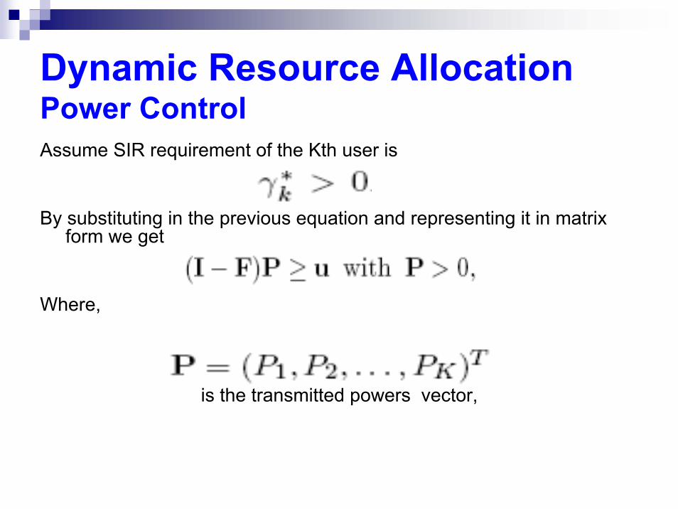
Dynamic Resource AllocationPower ControlAssume SIR requirement of the Kth user is
By substituting in the previous equation and representing it in matrix form we get
Where,
is the transmitted powers vector,
Dynamic Resource AllocationPower Control
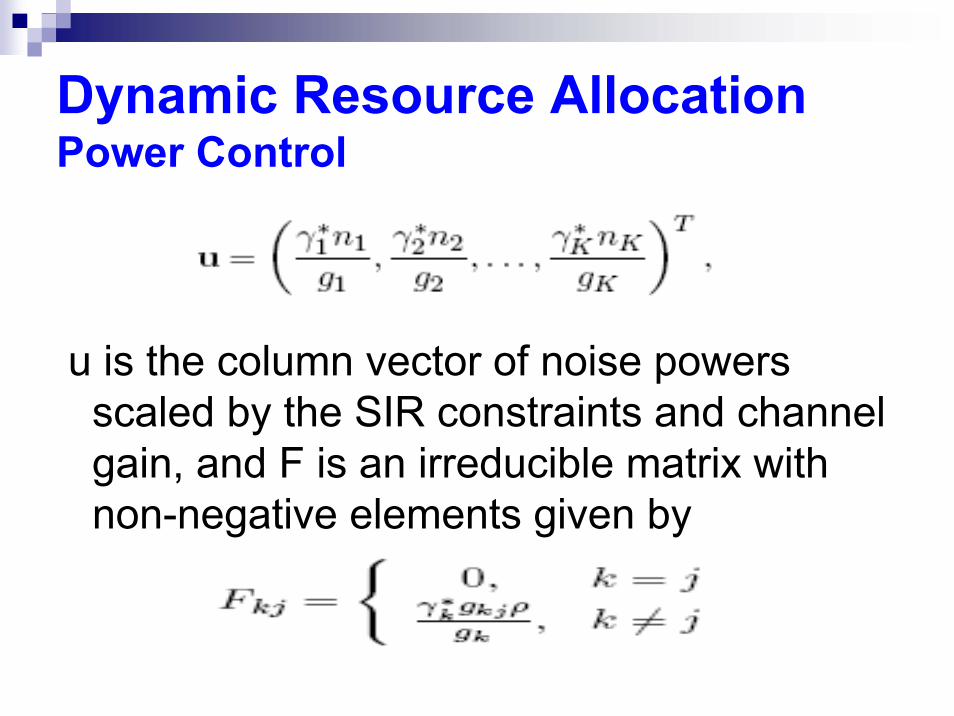
u is the column vector of noise powers scaled by the SIR constraints and channel gain, and F is an irreducible matrix with non-negative elements given by
Dynamic Resource AllocationPower Control
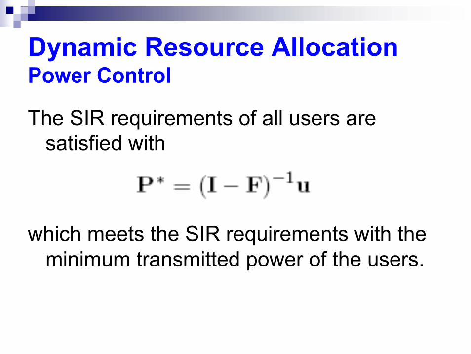
The SIR requirements of all users are satisfied with
which meets the SIR requirements with the minimum transmitted power of the users.

Dynamic Resource AllocationPower Control
Iterative Algorithm:
requires only SIR information at each transmitter.
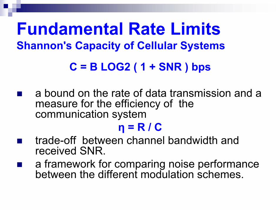
Fundamental Rate LimitsShannon's Capacity of Cellular Systems
C = B LOG2 ( 1 + SNR ) bps
a bound on the rate of data transmission and a measure for the efficiency of the communication system
η = R / Ctrade-off between channel bandwidth and received SNR.a framework for comparing noise performance between the different modulation schemes.
Fundamental Rate LimitsShannon's Capacity of Cellular Systems
Under full base stations cooperation assumption :base stations can be viewed as a single base station with multiple geographically-dispersed antennas and treated. The system then can be treated as MIMO ( in uplink an in down link)

Fundamental Rate LimitsShannon's Capacity of Cellular Systems
and by characterizing the propagation between mobiles and the multiple-antenna base station (uplink) using AWGN model with unity channel gain within a cell and a channel gain of α, 0 ≤ α ≤ 1, between cells

Fundamental Rate LimitsShannon's Capacity of Cellular Systems
Then, The per-user capacity which defined as the maximum possible rate that all user can maintain simultaneously is [1]
where B is the total system bandwidth, NoB is the noise PSD, K is the number of mobiles per cell, and P is the average transmit power of each mobile.

Fundamental Rate LimitsShannon's Capacity of Cellular Systems
Under no base station cooperation Assumption,So, receivers in each cell treat signal from other cell as interference reflects the practical design of cellular systemsUnfortunately, Shannon’s theory in channels with interference is mostly unsolved [1].
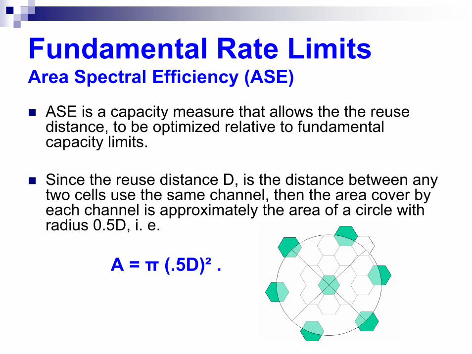
Fundamental Rate LimitsArea Spectral Efficiency (ASE)
ASE is a capacity measure that allows the the reuse distance, to be optimized relative to fundamental capacity limits.
Since the reuse distance D, is the distance between any two cells use the same channel, then the area cover by each channel is approximately the area of a circle with radius 0.5D, i. e.
A = π (.5D)² .
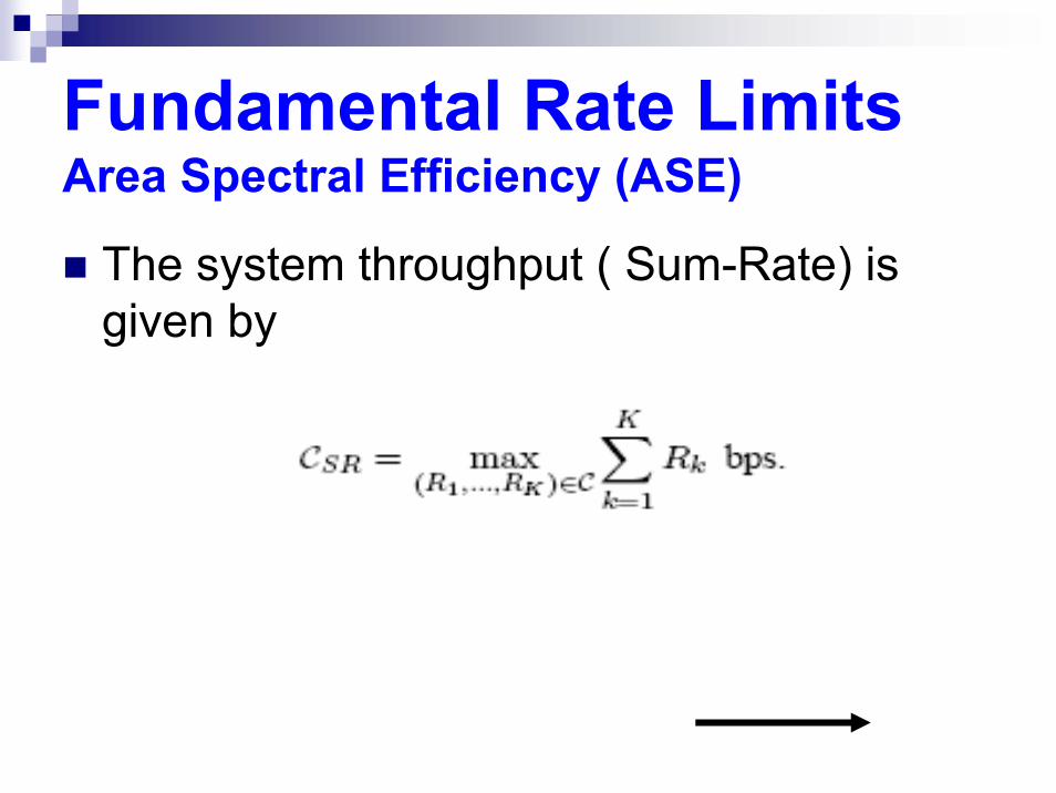
Fundamental Rate LimitsArea Spectral Efficiency (ASE)
The system throughput ( Sum-Rate) is given by

Fundamental Rate LimitsArea Spectral Efficiency (ASE)
The ASE of a cell is defined as the throughput/Hz/unit area that is supported by a cell’s resources

Case Study: AWGN TDMA System Uplink
K usersCell Radius RAll user assigned equal time slots Tk = 1/ KAll user transmit the same power P6 interferers (blue dots) to B.S. of the center cell

Case Study: AWGN TDMA System Uplink
Using Simplified Path Loss Model
Setting do = 1 m for our calculations yields

Case Study: AWGN TDMA System Uplink
The received signal power of the kth user (red dot) by his base station is
Interfernce caused by 6 interferers is
where 2 ≤ γ ≤ 4.
Case Study: AWGN TDMA System Uplink
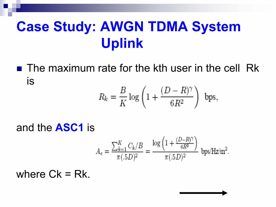
The maximum rate for the kth user in the cell Rkis
and the ASC1 is
where Ck = Rk.

Plots [1] of Ae versus D for γ=4 and γ=2 with the cell radius normalized to R=1

Case Study: AWGN TDMA System Uplink
If all interferers are at a distance D − R/2 from the base station of the center cell, then the ASE2 is

Plots of ASE2 along with ASE1 for γ = 4
CONCLUSION
Well designed cellular systems are interference-limited.The dynamic nature of cellular system in load and channel conditions requires a dynamic resource allocation to efficiently utilize these resources.Shannon’s Capacity of channels with interference (Cellular Systems) is a long-standing open problem.The optimization of reuse distance D relative capacity limits is based on ASE.
References
[1] Andrea Goldsmith, "Wireless Communications", Cambridge University Press, 2005.
[2] David Tse; Pramod Viswanath, "Fundamentals of Wireless Communication", Cambridge University Press, 2004.
[3] Simon Haykin, "Communication Systems", John Willy & sons, 2001.
[4] William Stallings, "Data and Computer Communications", Pearson Education, 2004.
[5] Lucent Technologies; Bell Labs Innovations, "GSM Introduction WL9001", 1998.


![[Paris Unity meetup] - Unity 3D en entreprise](https://img.pdfslide.net/doc/110x75/55a64ec51a28ab123f8b45ab/paris-unity-meetup-unity-3d-en-entreprise.jpg)