Embed Size (px)
Citation preview
CelluLine CGW-TS GSM Cellular Gateway Installation and Programming Manual


CelluLine CGW-TS – GSM Cellular Gateway
Installation and Programming Manual
CGWTS-M001A
Version 1, Release 1, December 2004

Copyright 2004 © ITS Telecom
NOTICE
No part of this document may be reproduced or transmitted in any form, by any means (electronic, photocopying, recording, or otherwise) without the prior written permission of ITS. Additional copies of this manual may be obtained from ITS.
ITS reserves the right to modify the hardware and software described in the manual without prior notice. However, changes made to the hardware or software described does not necessarily render this publication invalid.
WARRANTY
In the event this product proves to be defective in workmanship or materials within a period of one year from date of shipment, ITS will repair or replace the product at its discretion. Transportation will be the responsibility of the dealer/distributor.
Under no circumstances shall ITS be liable for consequential or special damages, loss of revenue or user/dealer expenses arising out of or in connection with the use or performance of the product, whether based on contract, tort, or any other legal agreement.
The following shall void the above warranty: malfunctions resulting from fire, accident, neglect, abuse, or acts of God; use of improper electrical power; or repair of, tampering with or alteration of the product by anyone other than ITS authorized personnel.
CelluLine CGW-TS: Installation and Programming Manual
Table of Contents 1 Introduction .............................................................1 1.1 Main Features.............................................................2 1.2 Physical Description ..................................................3 2 Installation ...............................................................5 2.1 Pre-Installation...........................................................5 2.2 Inserting the SIM Card...............................................6 2.3 Installing the CGW-TS ..............................................6 3 LED Status Indicators and Diagnostics .................9 3.1 LED Activity Status Indicators ................................10 3.2 LED Error Status Indicators.....................................11 3.3 Diagnostics...............................................................13 3.4 Antenna....................................................................14 4 DTMF Programming ............................................15 4.1 DTMF Programming Commands ............................16 5 Technical Data .......................................................21

CelluLine CGW-TS: Installation and Programming Manual 1
1 Introduction Your new ITS CelluLine CGW-TS is a cellular gateway that connects your PBX (Private Branch eXchange) directly to a GSM network, bypassing the landline carrier. By routing your outgoing calls made to cellular numbers through your new CGW-TS, you will be able to eliminate excessive interconnection fees charged by the landline carrier, thus cutting your telephone costs significantly.
Setting up the CGW-TS requires a simple connection from the analog trunk interface of your PBX-fxo to your new CGW-TS unit. Once connected, you insert the SIM card for your GSM cellular provider’s network into the unit, attach the antenna and plug in the power. You are now ready to make your first call from your phone extension directly through your GSM network. A detailed explanation of how to set up the CGW-TS can be found on page 5.
The CGW-TS has 6 LEDs that show the received signal level and other useful call progress information. A detailed explanation of the LED status indicators can be found on page 9.
You can program additional CGW-TS parameters, such as Audio volume control, Conversion Time-out and Restricted Digits, via DTMF commands. A detailed explanation of these parameters and others can be found on page 15.
2 CelluLine CGW-TS: Installation and Programming Manual
1.1 Main Features The CGW-TS has the following main features:
• Integrated dual-band GSM module (900/1800, 850/1900 MHz)
• 6 LEDs
Power indication (1)
Operational status (1)
Received signal level indicator (4)
• DTMF Programming
Prefix blocking (up to 10)
Conversation time-out
Reverse polarity signaling support
Audio volume control
• Supports DTMF dialing
• Line interface, 2-wire (RJ-11 connector)
• Plug & Play installation
• High quality audio
• Maintenance free
CelluLine CGW-TS: Installation and Programming Manual 3
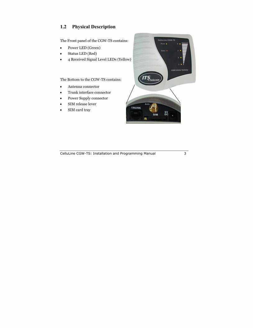
1.2 Physical Description
The Front panel of the CGW-TS contains:
• Power LED (Green)
• Status LED (Red)
• 4 Received Signal Level LEDs (Yellow)
The Bottom to the CGW-TS contains:
• Antenna connector
• Trunk interface connector
• Power Supply connector
• SIM release lever
• SIM card tray

CelluLine CGW-TS: Installation and Programming Manual 5
2 Installation Please read the following sections carefully before installing the CGW-TS. Improper installation of the unit can cause it damage and may invalidate its warranty.
2.1 Pre-Installation Your CGW-TS contains a GSM engine, which requires a SIM card from a local GSM network operator. You register the SIM card with the GSM operator the same way you normally register a new mobile GSM phone with the network operator.
The PIN code request must be OFF. You can set it to OFF by inserting it into any GSM mobile phone, or bring it to your local GSM Service Center.
Before you install the SIM card, disable all Call Forwarding modes (in the event of busy signal, absence, unavailability, etc.) and Call Waiting from the GSM operator.
6 CelluLine CGW-TS: Installation and Programming Manual
2.2 Inserting the SIM Card Follow these steps to properly insert the SIM card into your CGW-TS:
1. Hold the unit with the LEDs pointed down and the SIM insertion slot at the bottom of the unit facing you.
2. Use a pointed screwdriver to push the yellow SIM release lever, so that the SIM card tray moves towards you.
3. Remove the tray and place the SIM card inside (it will only fit in the tray one way).
4. Carefully replace the tray with the SIM card in the slot with contacts facing up and slide it back inside.
2.3 Installing the CGW-TS Follow these steps to properly install the CGW-TS:
1. On the bottom of the unit, insert the antenna in the “Ant.” Connector.
2. Mount the CGW-TS on the wall as a stand-alone unit.
The best location of the antenna is in an unrestricted high location. The LEDs indicate the level of GSM reception. The signal strength is updated every 15 seconds. Experiment to find the strongest signal. For more tips on where to place the antenna, see page 14.

CelluLine CGW-TS: Installation and Programming Manual 7
3. Connect the analog trunk interface of the PBX to the “TRUNK” line connector on the bottom of the unit.
4. Connect the supplied 9V DC adaptor to the unit. Plug it in the power supply.
5. The CGW-TS will begin initialization and registration. At the end of the process, the LEDs will display the GSM signal status.
For details on programming the CGW-TS, see Chapter 4.

CelluLine CGW-TS: Installation and Programming Manual 9
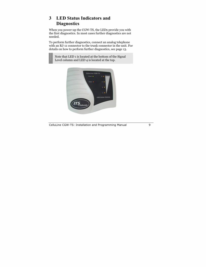
3 LED Status Indicators and Diagnostics
When you power-up the CGW-TS, the LEDs provide you with the first diagnostics. In most cases further diagnostics are not needed.
To perform further diagnostics, connect an analog telephone with an RJ-11 connector to the trunk connector in the unit. For details on how to perform further diagnostics, see page 13.
Note that LED 1 is located at the bottom of the Signal Level column and LED 4 is located at the top.
10 CelluLine CGW-TS: Installation and Programming Manual
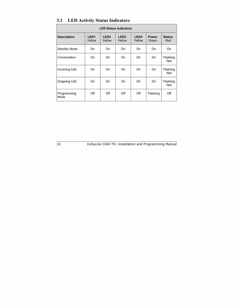
3.1 LED Activity Status Indicators LED Status Indicators
Description
LED1 Yellow
LED2 Yellow
LED3 Yellow
LED4 Yellow
Power Green
Status Red
Standby Mode On On On On On On
Conversation On On On On On Flashing fast
Incoming Call On On On On On Flashing fast
Outgoing Call On On On On On Flashing fast
Programming Mode
Off Off Off Off Flashing Off
CelluLine CGW-TS: Installation and Programming Manual 11
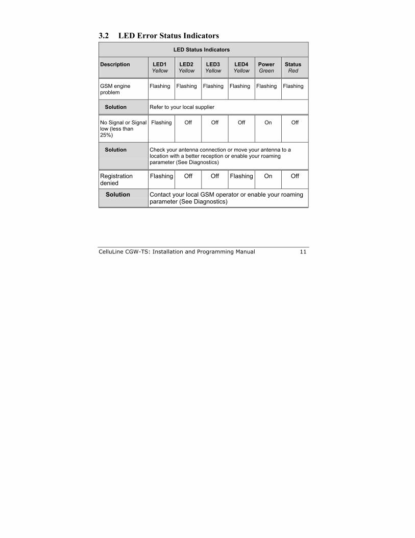
3.2 LED Error Status Indicators LED Status Indicators
Description
LED1 Yellow
LED2 Yellow
LED3 Yellow
LED4 Yellow
Power Green
Status Red
GSM engine problem
Flashing Flashing Flashing Flashing Flashing Flashing
Solution Refer to your local supplier
No Signal or Signal low (less than 25%)
Flashing Off Off Off On Off
Solution
Check your antenna connection or move your antenna to a location with a better reception or enable your roaming parameter (See Diagnostics)
Registration denied
Flashing Off Off Flashing On Off
Solution
Contact your local GSM operator or enable your roaming parameter (See Diagnostics)
12 CelluLine CGW-TS: Installation and Programming Manual
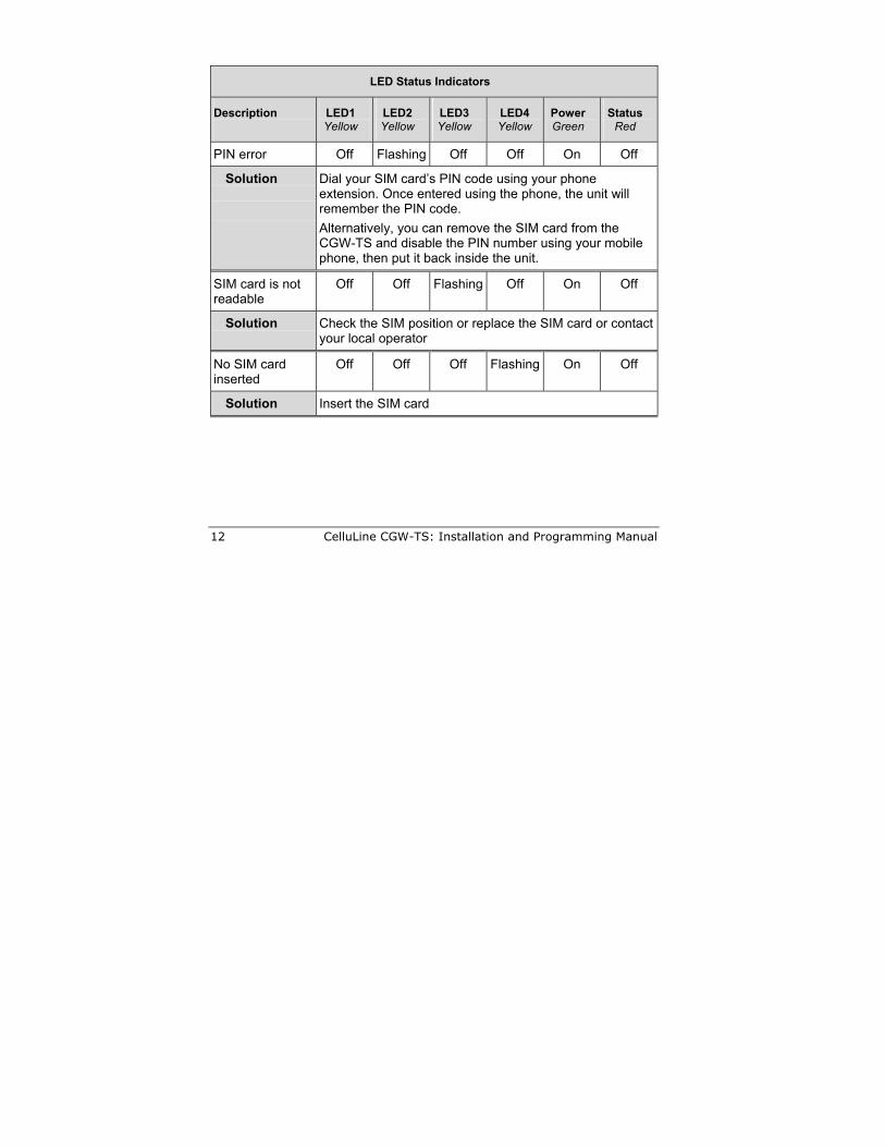
LED Status Indicators
Description
LED1 Yellow
LED2 Yellow
LED3 Yellow
LED4 Yellow
Power Green
Status Red
PIN error Off Flashing Off Off On Off
Solution
Dial your SIM card’s PIN code using your phone extension. Once entered using the phone, the unit will remember the PIN code. Alternatively, you can remove the SIM card from the CGW-TS and disable the PIN number using your mobile phone, then put it back inside the unit.
SIM card is not readable
Off Off Flashing Off On Off
Solution
Check the SIM position or replace the SIM card or contact your local operator
No SIM card inserted
Off Off Off Flashing On Off
Solution Insert the SIM card
CelluLine CGW-TS: Installation and Programming Manual 13
3.3 Diagnostics You can perform additional diagnostics by connecting a 4-pin RJ-11 connector from the analog telephone to the trunk connector of your CGW-TS.
To begin diagnostics, pick up the phone’s receiver. If you hear:
• Continuous dial tone: the unit is working correctly and you can now start to program it.
• Busy tone: Check which LEDs are lit and find the error in Section 3.2. You cannot program the unit until you get a continuous dial tone.
• No dial tone: The GSM network signal is too low to complete registration. Remove your SIM card and replace it with a card from a GSM network that provides a higher signal level. Enable the roaming parameter (see page 18), then replace the SIM card with your original SIM card.
Note that all cellular calls you now make from your CGW-TS will be routed through the alternate GSM network that you used to complete your registration.
14 CelluLine CGW-TS: Installation and Programming Manual
3.4 Antenna Some locations that you set up your CGW-TS can provide only a low signal level. To improve the signal level, the technician should try the following:
• Put the antenna near a window.
• Replace the supplied antenna with one having a better Gain (7 dB).
• Replace the supplied antenna with an outdoor one and place it outside the building.
• Place a metal plate under the foot of the antenna (minimum size: 10 x 20 cm – maximum size: 40 x 55 cm).
• Place the antenna on a different floor. If you do this, you may also want to move the unit with the antenna and connect a cable between the unit and the PBX.
• Verify that the distance between the antenna and any surrounding antennas is at least 35 cm.
• Position the antenna vertically and pointing upwards.
CelluLine CGW-TS: Installation and Programming Manual 15
4 DTMF Programming You can program your CGW-TS via DTMF as follows:
1. If the unit is connected to the PBX, remove the cable from the “Trunk” interface connector of the unit.
2. Connect an analog telephone directly to the “Line” interface connector of the unit.
3. Verify that the SIM card is properly installed and the power supply is connected.
4. Pick up the phone, wait or the dial tone to make sure the unit is working correctly, then dial *900.
5. After you hear the confirmation tone, enter the password (default=1234).
• To exit from the Programming mode, dial *900 or hang up the telephone.
• If you do not enter digits for 45 seconds, the unit will automatically exit the Programming mode.
• When you enter an incorrect command, the CGW-TS will “beep” an alert one time.
• When you enter a correct command, the CGW-TS will “beep” an alert two times.
16 CelluLine CGW-TS: Installation and Programming Manual
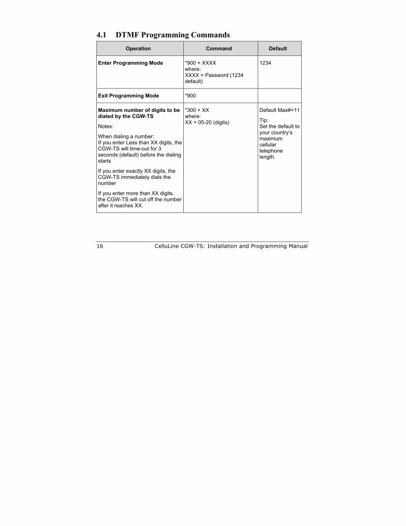
4.1 DTMF Programming Commands Operation Command Default
Enter Programming Mode *900 + XXXX where: XXXX = Password (1234 default)
1234
Exit Programming Mode *900
Maximum number of digits to be dialed by the CGW-TS
Notes:
When dialing a number: If you enter Less than XX digits, the CGW-TS will time-out for 3 seconds (default) before the dialing starts
If you enter exactly XX digits, the CGW-TS immediately dials the number
If you enter more than XX digits, the CGW-TS will cut off the number after it reaches XX.
*300 + XX where: XX = 05-20 (digits)
Default Max#=11
Tip: Set the default to your country’s maximum cellular telephone length.
CelluLine CGW-TS: Installation and Programming Manual 17
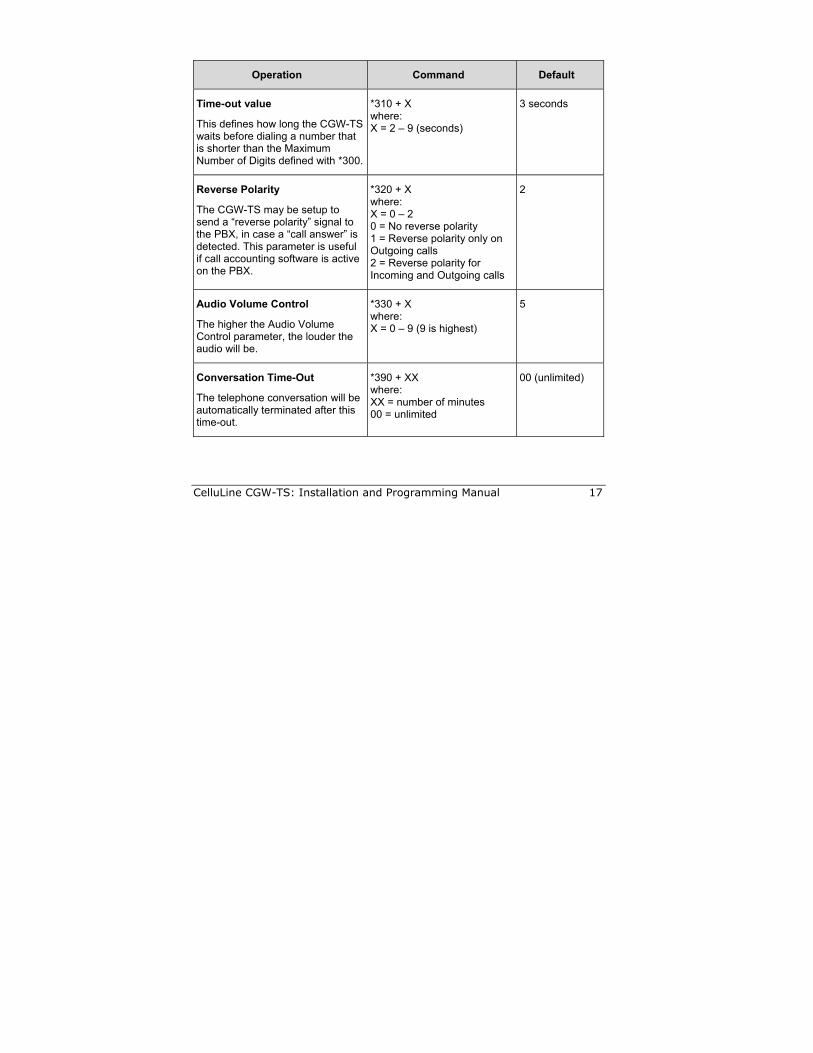
Operation Command Default
Time-out value
This defines how long the CGW-TS waits before dialing a number that is shorter than the Maximum Number of Digits defined with *300.
*310 + X where: X = 2 – 9 (seconds)
3 seconds
Reverse Polarity
The CGW-TS may be setup to send a “reverse polarity” signal to the PBX, in case a “call answer” is detected. This parameter is useful if call accounting software is active on the PBX.
*320 + X where: X = 0 – 2 0 = No reverse polarity 1 = Reverse polarity only on Outgoing calls 2 = Reverse polarity for Incoming and Outgoing calls
2
Audio Volume Control
The higher the Audio Volume Control parameter, the louder the audio will be.
*330 + X where: X = 0 – 9 (9 is highest)
5
Conversation Time-Out
The telephone conversation will be automatically terminated after this time-out.
*390 + XX where: XX = number of minutes 00 = unlimited
00 (unlimited)
18 CelluLine CGW-TS: Installation and Programming Manual
Operation Command Default
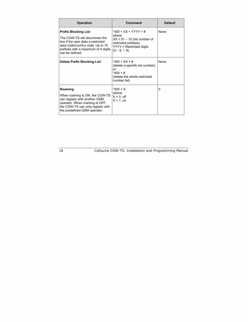
Prefix Blocking List
The CGW-TS will disconnect the line if the user dials a restricted area code/country code. Up to 10 prefixes with a maximum of 4 digits can be defined.
*400 + XX + YYYY + # where: XX = 01 – 10 (list number of restricted prefixes) YYYY = Restricted digits (0 – 9, *, #)
None
Delete Prefix Blocking List *400 + XX + # (delete a specific list number) or *400 + # (delete the whole restricted number list)
None
Roaming
When roaming is ON, the CGW-TS can register with another GSM operator. When roaming is OFF, the CGW-TS can only register with the predefined GSM operator.
*500 + X where: X = 0, off X = 1, on
0
CelluLine CGW-TS: Installation and Programming Manual 19
Operation Command Default
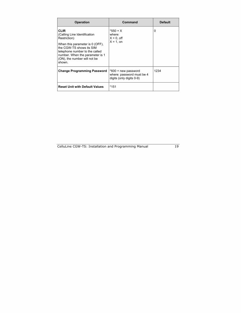
CLIR (Calling Line Identification Restriction)
When this parameter is 0 (OFF), the CGW-TS shows its SIM telephone number to the called number. When the parameter is 1 (ON), the number will not be shown.
*550 + X where: X = 0, off X = 1, on
0
Change Programming Password *600 + new password where: password must be 4 digits (only digits 0-9)
1234
Reset Unit with Default Values *151

CelluLine CGW-TS: Installation and Programming Manual 21
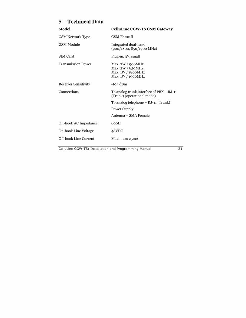
5 Technical Data Model CelluLine CGW-TS GSM Gateway
GSM Network Type GSM Phase II
GSM Module Integrated dual-band (900/1800, 850/1900 MHz)
SIM Card Plug-in, 3V, small
Transmission Power Max. 2W / 900MHz Max. 2W / 850MHz Max. 1W / 1800MHz Max. 1W / 1900MHz
Receiver Sensitivity -104 dBm
Connections To analog trunk interface of PBX – RJ-11 (Trunk) (operational mode)
To analog telephone – RJ-11 (Trunk)
Power Supply
Antenna – SMA Female
Off-hook AC Impedance 600Ω
On-hook Line Voltage 48VDC
Off-hook Line Current Maximum 25mA
22 CelluLine CGW-TS: Installation and Programming Manual
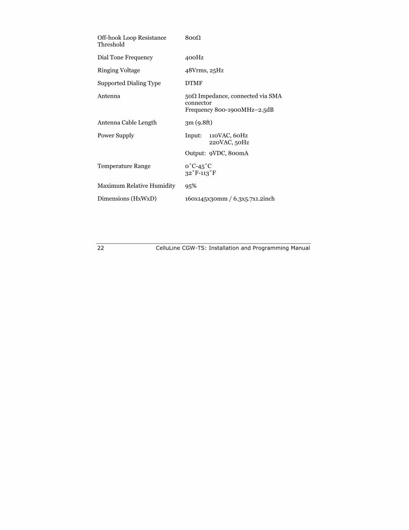
Off-hook Loop Resistance Threshold
800Ω
Dial Tone Frequency 400Hz
Ringing Voltage 48Vrms, 25Hz
Supported Dialing Type DTMF
Antenna 50Ω Impedance, connected via SMA connector Frequency 800-1900MHz–2.5dB
Antenna Cable Length 3m (9.8ft)
Power Supply Input: 110VAC, 60Hz 220VAC, 50Hz
Output: 9VDC, 800mA
Temperature Range 0˚C-45˚C 32˚F-113˚F
Maximum Relative Humidity 95%
Dimensions (HxWxD) 160x145x30mm / 6.3x5.7x1.2inch

ITS 29 Hametzuda Street 58001 Azur, Israel Tel: +972-3-5576866 Fax: +972-3-5576942 www.its-tel.com
[email protected] Control#: CGWTS-M001A