Embed Size (px)
Citation preview
This content has been downloaded from IOPscience. Please scroll down to see the full text.
Download details:
IP Address: 128.104.200.240
This content was downloaded on 06/01/2015 at 21:51
Please note that terms and conditions apply.
Cellulose nanofiber-templated three-dimension TiO2 hierarchical nanowire network for
photoelectrochemical photoanode
View the table of contents for this issue, or go to the journal homepage for more
2014 Nanotechnology 25 504005
(http://iopscience.iop.org/0957-4484/25/50/504005)
Home Search Collections Journals About Contact us My IOPscience
Cellulose nanofiber-templated three-dimension TiO2 hierarchical nanowirenetwork for photoelectrochemicalphotoanode
Zhaodong Li1, Chunhua Yao1, Fei Wang1, Zhiyong Cai3 andXudong Wang1,2
1Department of Materials Science and Engineering, University of Wisconsin-Madison, Madison, WI53706, USA2Beijing Institute of Nanoenergy and Nanosystems, Chinese Academy of Sciences, Beijing 100083,People’s Republic of China3 Forest Products Laboratory, USDA Forest Service, Madison, WI 53726, USA
E-mail: [email protected] and [email protected]
Received 29 June 2014, revised 23 August 2014Accepted for publication 5 September 2014Published 26 November 2014
AbstractThree dimensional (3D) nanostructures with extremely large porosity possess a great promise forthe development of high-performance energy harvesting and storage devices. In this paper, wedeveloped a high-density 3D TiO2 fiber-nanorod (NR) heterostructure for efficientphotoelectrochemical (PEC) water splitting. The hierarchical structure was synthesized on aZnO-coated cellulose nanofiber (CNF) template using atomic layer deposition (ALD)-based thinfilm and NR growth procedures. The tubular structure evolution was in good agreement with therecently discovered vapor-phase Kirkendall effect in high-temperature ALD processes. The NRmorphology was formed via the surface-reaction-limited pulsed chemical vapor deposition(SPCVD) mechanism. Under Xenon lamp illumination without and with an AM 1.5G filter or aUV cut off filter, the PEC efficiencies of a 3D TiO2 fiber-NR heterostructure were found to be22–249% higher than those of the TiO2-ZnO bilayer tubular nanofibers and TiO2 nanotubenetworks that were synthesized as reference samples. Such a 3D TiO2 fiber-NR heterostructureoffers a new route for a cellulose-based nanomanufacturing technique, which can be used forlarge-area, low-cost, and green fabrication of nanomaterials as well as their utilizations forefficient solar energy harvesting and conversion.
Keywords: atomic layer deposition, cellulose nanofiber, 3D structure
(Some figures may appear in colour only in the online journal)
1. Introduction
Photoelectrochemical (PEC) water splitting has receivedconsiderable attention in the development of solar fuel tech-nologies to relieve our dependence on fossil fuels and toreduce greenhouse gas emissions [1–4]. High-performancephotoelectrodes of PEC systems demand broad-band andhigh-percentage light absorption; instantaneous and low-losscharge separation, collection and transportation; and large and
clean electrode—electrolyte interfaces [4–11]. Three-dimen-sional (3D) branched nanowire (NW)/nanorod (NR) archi-tectures are considered to be excellent candidates for PECphotoelectrode development. They are composed of highlyconductive core NWs that are fully covered with dense andactive NR branches [10, 12–16]. Their high performance is aresult of their extremely large surface area density, longoptical paths, and the potential to achieve rapid photo-generated electron-hole separation and transport. Our recent
Nanotechnology
Nanotechnology 25 (2014) 504005 (10pp) doi:10.1088/0957-4484/25/50/504005
0957-4484/14/504005+10$33.00 © 2014 IOP Publishing Ltd Printed in the UK1
development of a surface-reaction-limited pulsed chemicalvapor deposition (SPCVD) technique, as a derivative ofatomic layer deposition (ALD), enabled uniform growth ofhigh-density NR branches on ultra-compact NW arrays,which led to significant performance gain in solar energyconversion [10, 12].
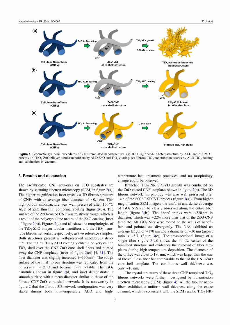
Natural cellulose-based nanomaterials such as cellulosenanofibers (CNFs) are another type of widely used large-scalerenewable 3D mesoporous structures owing to their greatabundance, low cost, bio-compatibility, and degradability[17–20]. They are composed of elementary cellulose fibrilsand show comparable mechanical properties (e.g., Young’smodulus and tensile strength) as other fibrous materials (e.g.,carbon fibers and glass fibers) [21]. CNFs also exhibit sig-nificant absorbability to both hydrophilic and hydrophobicmaterials [22]. They are therefore a remarkable template forprocessing functional 3D nanostructures with extremely largeporosity and possess great promise for the development ofhigh-performance energy harvesting and storage devices. Forexample, nanofibrillated cellulose was utilized as a papersubstrate to fabricate thin film transistors achieving hightransparency and flexibility of the device [20]; nanostructurednetworks of cellulose-graphite platelet composites wereapplied as Li-ion battery anodes, demonstrating excellentflexibility and good cycling performance [23, 24]; porouscellulose-templated TiO2 nanostructures were used in photo-catalytic and dye-sensitized solar cells, exhibiting sig-nificantly enlarged surface area and improved electrontransport properties [25, 26]; and cellulose/polyaniline nano-composites were developed for supercapacitors withenhanced mass-specific capacitance [27]. Combining thesuccessful exploration of CNF-templated nanostructures withbranched functional NR configurations would lead to a novelhierarchical nanostructure with further enhanced PEC per-formance and photoelectrode manufacturability. In this paper,we integrated the SPCVD technique for synthesizing high-density TiO2 NR branches with mesoporous CNF templates.The CNF framework was well preserved under high deposi-tion temperature by introducing ZnO overcoating. The ZnOlayer was completely converted into TiO2 during growth,following the Kirkendall effect [28]. To the best of ourknowledge, this is the first time that high density NR brancheshave been grown into mesoporous CNF networks, whichfurther enlarges the surface area as well as introduces newfunctionality. Compared to other CNF-templated mesoporousnanostructures (i.e., TiO2-ZnO bilayer tubular nanofibersnetworks and TiO2 nanotubes networks), a 3D TiO2 fiber-NRheterostructure exhibited significantly enhanced photocurrentand PEC efficiency, owing to their large surface area andgood electrical conductivity.
2. Experimental section
2.1. Fabrication of CNF template
The CNFs used in our experiments were tetra-methylpiperidine-1-oxy (TEMPO) oxidized wood pulp fibers,
which were prepared according to the method reported bySaito et al [29, 30]. In particular, the CNFs’ hydrogel solution(0.4 wt%) was obtained by mechanically homogenizing theTEMPO-treated wood pulp fibers on an M-110EH-30Microfluidizer (Microfluidics, Newton, MA, USA) with aseries of 200- and 87 μm chambers via two pass-throughs.After printing the CNFs’ hydrogel on a fluorine doped tinoxide (FTO) glass substrate, the substrate with hydrogel filmwas frozen in a liquid N2 and ethanol bath. The substrate wasthen placed into the vacuum chamber of a Labconco 4.5Freeze Dryer (Labconco, Kansas City, MO, USA) immedi-ately, remaining 12 h at room temperature with a base pres-sure of ∼35 mTorr, where sublimation of the ice yielded ananofibrous structure cellulose film, 10 μm thick on the FTO.
2.2. Fabrication of 3D TiO2 fiber-NR heterostructure
The as-prepared CNF nanostructures on FTO substrates wereloaded into an ALD chamber for ZnO overcoating at 150 °C.In one growth cycle, H2O and diethylzinc vapor precursorswere pulsed into the chamber for 1 s each and separated by N2
purging for 60 s. The 150-cycle ALD growth yielded a30 nm-thick ZnO film covering the CNFs. This CNF-ZnOcore-shell structure on FTO substrates was then used forSPCVD TiO2 NR branch growth. Similar to the ALD process,400 cycles of alternating reactions were conducted at 600 °C.Each cycle consisted of 1 s H2O pulsing + 60 s N2
purging + 1 s titanium tetrachloride (TiCl4) pulsing + 60 s N2
purging. Through this process, TiO2 NRs were uniformlygrown on the fibrous backbones.
In order to compare the PEC performance, both CNF-templated TiO2-ZnO bilayer tubular nanofibers and fibrousTiO2 nanotubes networks were prepared. For the TiO2-ZnOsamples, 400 cycles of ALD TiO2 films were coated on CNF-ZnO core-shell nanofibers. The deposition was performed at300 °C with 1 s H2O pulsing + 60 s N2 purging + 1 s titaniumtetrachloride (TiCl4) pulsing + 60 s N2 purging for each cycle.The fibrous TiO2 nanotubes network was synthesized via a400-cycle ALD TiO2 coating at 150 °C on a CNF templateand sintered at 600 °C to crystallize the TiO2 coating andremove CNF templates [4]. The fabrication processes of threekinds of samples are schematically illustrated in figure 1.
2.3. PEC characterization
PEC characterizations were performed in a 1 mol L−1 KOH(pH= 14) aqueous solution using a three-electrode electro-chemical cell configuration. The saturated calomel electrode(SCE) was used as the reference electrode, and a Pt wire wasused as the counter electrode. All electrodes were connectedto a potentiostat system (Metrohm Inc., Riverview, FL) for J–V measurement. Light illumination was provided by a 150WXe arc lamp (Newport Corporation, Irvine, CA), and theintensity at the PEC anode position was adjusted to be100 mW cm−2. An AM 1.5G filter and a UV cutoff filter werealso utilized with the lamp for PEC characterizations.
2
Nanotechnology 25 (2014) 504005 Z Li et al
3. Results and discussion
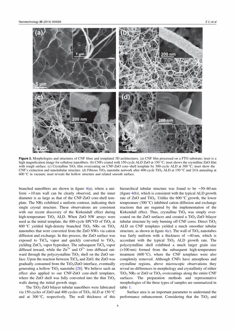
The as-fabricated CNF networks on FTO substrates areshown by scanning electron microscopy (SEM) in figure 2(a).The higher-magnification inset reveals a 3D fibrous structureof CNFs with an average fiber diameter of ∼0.1 μm. Thishigh-porous nanostructure was well preserved after 150 °CALD of ZnO thin film conformal coating (figure 2(b)). Thesurface of the ZnO-coated CNF was relatively rough, which isa result of the polycrystalline nature of the ZnO coating (Insetof figure 2(b)). Figures 2(c) and (d) show the morphologies ofthe TiO2-ZnO bilayer tubular nanofibers and the TiO2 nano-tube fibrous networks, respectively, as two reference samples.Both structures present a well-preserved nanofibrous struc-ture. The 300 °C TiO2 ALD coating yielded a polycrystallineTiO2 shell over the CNF-ZnO core–shell fibers and burnedaway the CNF templates (inset of figure 2(c)) [4, 31]. Thefiber diameter was slightly increased (∼190 nm). The roughsurface of the final fibrous structure was replicated from thepolycrystalline ZnO and became more notable. The TiO2
nanotubes shown in figure 2(d) and inset demonstrated asmooth surface with a mean diameter similar to those of thefibrous CNF-ZnO core–shell network. It is noteworthy infigure 2 that the fibrous 3D network configuration was verystable during both low-temperature ALD and high-
temperature heat treatment processes, and no morphologychange could be observed.
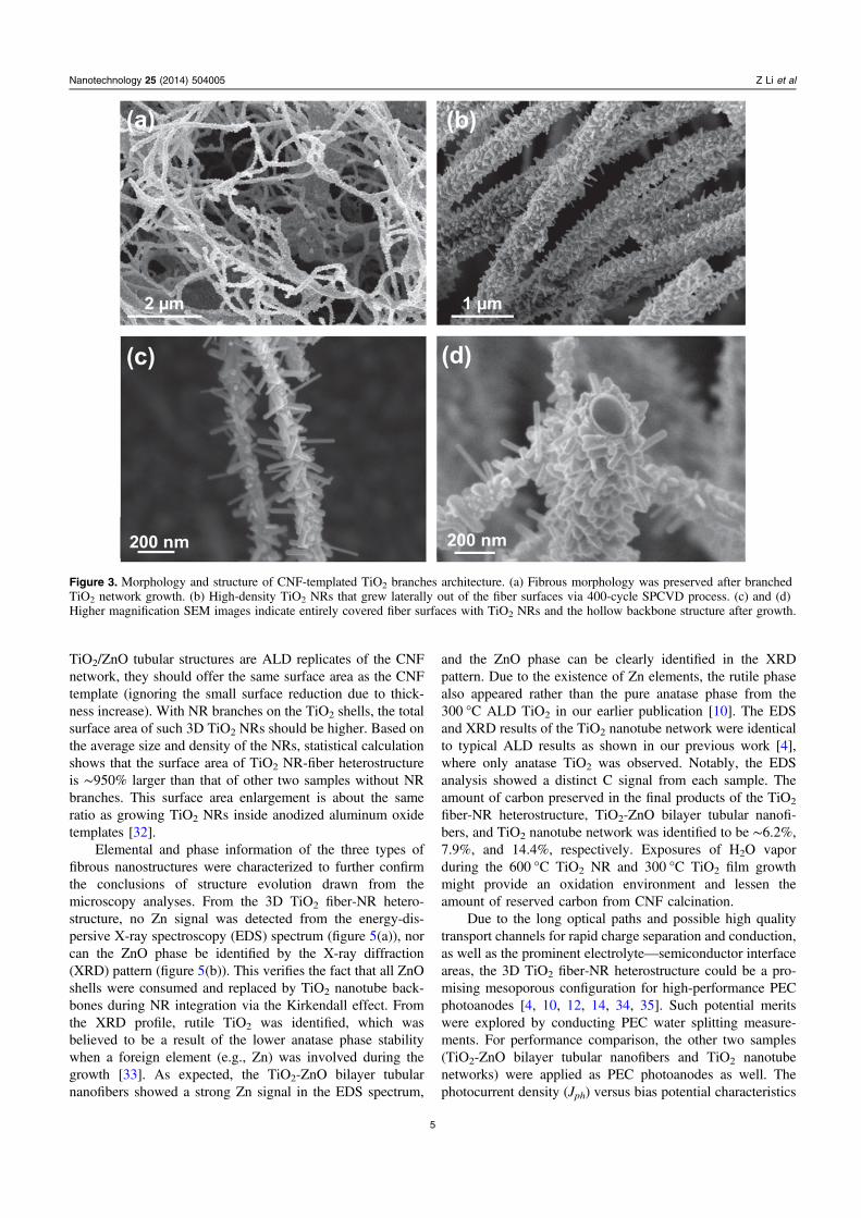
Branched TiO2 NR SPCVD growth was conducted onthe ZnO-coated CNF templates shown in figure 2(b). The 3Dfibrous network morphology was also well preserved after14 h of the 600 °C SPCVD process (figure 3(a)). From highermagnification SEM images, the uniform and dense coverageof TiO2 NRs can be clearly observed along the entire fiberlength (figure 3(b)). The fibers’ trunks were ∼220 nm indiameter, which was ∼22% more than that of the ZnO-CNFtemplate. All TiO2 NRs were rooted on the walls of nanofi-bers and pointed out divergently. The NRs exhibited anaverage length of ∼170 nm and a diameter of ∼30 nm (aspectratio is ∼5.7) (figure 3(c)). The cross-sectional image of asingle fiber (figure 3(d)) shows the hollow center of thebranched structure and evidences the removal of fiber tem-plates during high-temperature deposition. The diameter ofthe orifice was close to 180 nm, which was larger than the sizeof the cellulose fiber but comparable to that of the CNF-ZnOcore-shell template. The continuous wall thickness wasonly ∼10 nm.
The crystal structures of these three CNF-templated TiO2
fibrous networks were further investigated by transmissionelectron microscopy (TEM) (figure 4). All the tubular nano-fibers exhibited a uniform wall thickness along the entirechannel, which is consistent with the SEM results. TiO2 NR-
Figure 1. Schematic synthesis procedures of CNF-templated nanostructures. (a) 3D TiO2 fiber-NR heterostructure by ALD and SPCVDprocess. (b) TiO2-ZnO bilayer tubular nanofibers by ALD ZnO and TiO2 coating. (c) Fibrous TiO2 nanotubes networks by ALD TiO2 coatingand calcination in vacuum.
3
Nanotechnology 25 (2014) 504005 Z Li et al
branched nanofibers are shown in figure 4(a), where a uni-form ∼10 nm wall can be clearly observed, and the innerdiameter is as large as that of the CNF-ZnO core-shell tem-plate. The NRs exhibited a uniform contrast, indicating theirsingle crystal structure. These observations are consistentwith our recent discovery of the Kirkendall effect duringhigh-temperature TiO2 ALD. When ZnO NW arrays wereused as the initial template, the 400-cycle SPCVD of TiO2 at600 °C yielded high-density branched TiO2 NRs on TiO2
nanotubes that were converted from the ZnO NWs via cationdiffusion and exchange. In this process, the ZnO surface wasexposed to TiCl4 vapor and quickly converted to TiO2,yielding ZnCl2 vapor byproduct. The subsequent TiCl4 vapordiffused inward, while the Zn2+ and O2− ions diffused out-ward through the polycrystalline TiO2 shell on the ZnO sur-face. Upon the reaction between TiCl4 and ZnO, the ZnO wasgradually consumed from the TiO2/ZnO interface, eventuallygenerating a hollow TiO2 nanotube [28]. We believe such aneffect also applied to our CNF-ZnO core-shell templates,where the ZnO shell was fully converted into the thin TiO2
walls during the initial growth stage.The TiO2-ZnO bilayer tubular nanofibers were fabricated
via 150 cycles of ZnO and 400 cycles of TiO2 ALD at 150 °Cand at 300 °C, respectively. The wall thickness of this
hierarchical tubular structure was found to be ∼50–60 nm(figure 4(b)), which is consistent with the typical ALD growthrate of ZnO and TiO2. Unlike the 600 °C growth, the lowertemperature (300 °C) inhibited cation diffusion and exchangereactions that are required by the implementation of theKirkendall effect. Thus, crystalline TiO2 was simply over-coated on the ZnO surfaces and created a TiO2-ZnO bilayertubular structure by only burning off CNF cores. Direct TiO2
ALD on CNF templates yielded a much smoother tubularstructure, as shown in figure 4(c). The wall of TiO2 nanotubeswas fairly uniform with a thickness of ∼40 nm, which isaccordant with the typical TiO2 ALD growth rate. Thepolycrystalline shell exhibited a much larger grain size(>100 nm) formed from the subsequent high-temperaturetreatment (600 °C), where the CNF templates were alsocompletely removed. Although CNFs have amorphous andcrystalline regions, above microscopic observations theyreveal no differences in morphology and crystallinity of eitherTiO2 NRs or ZnO or TiO2 overcoatings along the entire CNFsurfaces. The preparation methods and representativemorphologies of the three types of samples are summarized intable 1.
Surface area is an important parameter to understand theperformance enhancement. Considering that the TiO2 and
Figure 2. Morphologies and structures of CNF films and templated 3D architectures. (a) CNF film processed on a FTO substrate; inset is ahigh magnification image for cellulose nanofibers. (b) CNFs coated with 150-cycle ALD ZnO at 150 °C; inset shows the crystalline ZnO filmwith rough surface. (c) Crystalline TiO2 film overcoating on CNF-ZnO core–shell template by 300-cycle ALD at 300 °C; inset show theCNF’s extinction and nanotubular structure. (d) Fibrous TiO2 nanotube network after 400-cycle TiO2 ALD at 150 °C and 24 h annealing at600 °C in vacuum; inset reveals the hollow structure and related smooth surface.
4
Nanotechnology 25 (2014) 504005 Z Li et al
TiO2/ZnO tubular structures are ALD replicates of the CNFnetwork, they should offer the same surface area as the CNFtemplate (ignoring the small surface reduction due to thick-ness increase). With NR branches on the TiO2 shells, the totalsurface area of such 3D TiO2 NRs should be higher. Based onthe average size and density of the NRs, statistical calculationshows that the surface area of TiO2 NR-fiber heterostructureis ∼950% larger than that of other two samples without NRbranches. This surface area enlargement is about the sameratio as growing TiO2 NRs inside anodized aluminum oxidetemplates [32].
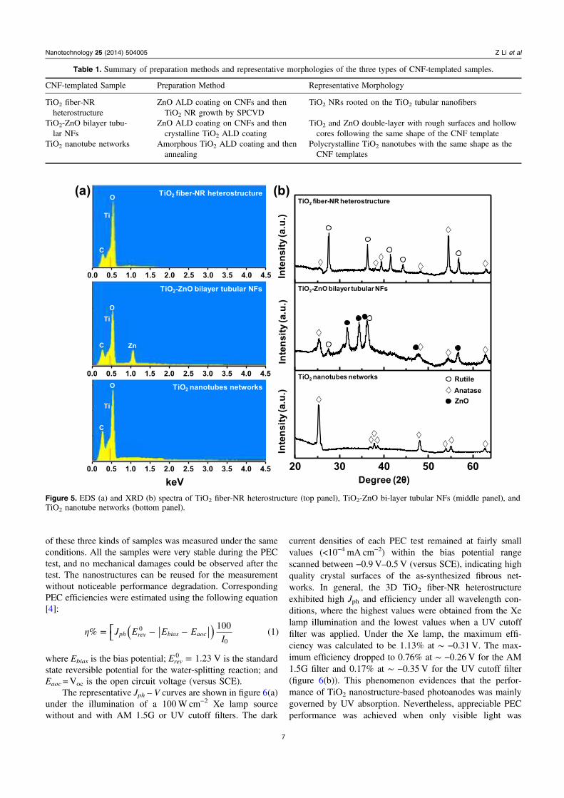
Elemental and phase information of the three types offibrous nanostructures were characterized to further confirmthe conclusions of structure evolution drawn from themicroscopy analyses. From the 3D TiO2 fiber-NR hetero-structure, no Zn signal was detected from the energy-dis-persive X-ray spectroscopy (EDS) spectrum (figure 5(a)), norcan the ZnO phase be identified by the X-ray diffraction(XRD) pattern (figure 5(b)). This verifies the fact that all ZnOshells were consumed and replaced by TiO2 nanotube back-bones during NR integration via the Kirkendall effect. Fromthe XRD profile, rutile TiO2 was identified, which wasbelieved to be a result of the lower anatase phase stabilitywhen a foreign element (e.g., Zn) was involved during thegrowth [33]. As expected, the TiO2-ZnO bilayer tubularnanofibers showed a strong Zn signal in the EDS spectrum,
and the ZnO phase can be clearly identified in the XRDpattern. Due to the existence of Zn elements, the rutile phasealso appeared rather than the pure anatase phase from the300 °C ALD TiO2 in our earlier publication [10]. The EDSand XRD results of the TiO2 nanotube network were identicalto typical ALD results as shown in our previous work [4],where only anatase TiO2 was observed. Notably, the EDSanalysis showed a distinct C signal from each sample. Theamount of carbon preserved in the final products of the TiO2
fiber-NR heterostructure, TiO2-ZnO bilayer tubular nanofi-bers, and TiO2 nanotube network was identified to be ∼6.2%,7.9%, and 14.4%, respectively. Exposures of H2O vaporduring the 600 °C TiO2 NR and 300 °C TiO2 film growthmight provide an oxidation environment and lessen theamount of reserved carbon from CNF calcination.
Due to the long optical paths and possible high qualitytransport channels for rapid charge separation and conduction,as well as the prominent electrolyte—semiconductor interfaceareas, the 3D TiO2 fiber-NR heterostructure could be a pro-mising mesoporous configuration for high-performance PECphotoanodes [4, 10, 12, 14, 34, 35]. Such potential meritswere explored by conducting PEC water splitting measure-ments. For performance comparison, the other two samples(TiO2-ZnO bilayer tubular nanofibers and TiO2 nanotubenetworks) were applied as PEC photoanodes as well. Thephotocurrent density (Jph) versus bias potential characteristics
Figure 3. Morphology and structure of CNF-templated TiO2 branches architecture. (a) Fibrous morphology was preserved after branchedTiO2 network growth. (b) High-density TiO2 NRs that grew laterally out of the fiber surfaces via 400-cycle SPCVD process. (c) and (d)Higher magnification SEM images indicate entirely covered fiber surfaces with TiO2 NRs and the hollow backbone structure after growth.
5
Nanotechnology 25 (2014) 504005 Z Li et al
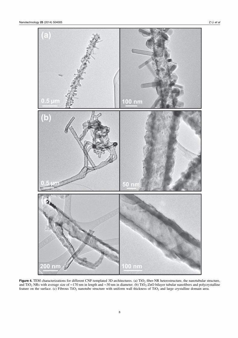
Figure 4. TEM characterizations for different CNF-templated 3D architectures. (a) TiO2 fiber-NR heterostructure, the nanotubular structure,and TiO2 NRs with average size of ∼170 nm in length and ∼30 nm in diameter. (b) TiO2-ZnO bilayer tubular nanofibers and polycrystallinefeature on the surface. (c) Fibrous TiO2 nanotube structure with uniform wall thickness of TiO2 and large crystalline domain area.
6
Nanotechnology 25 (2014) 504005 Z Li et al
of these three kinds of samples was measured under the sameconditions. All the samples were very stable during the PECtest, and no mechanical damages could be observed after thetest. The nanostructures can be reused for the measurementwithout noticeable performance degradation. CorrespondingPEC efficiencies were estimated using the following equation[4]:
⎡⎣η = − −( )J E E EI
%100
(1)ph rev bias aoc0
0
where Ebias is the bias potential; =E 1.23 Vrev0 is the standard
state reversible potential for the water-splitting reaction; andEaoc=Voc is the open circuit voltage (versus SCE).
The representative Jph – V curves are shown in figure 6(a)under the illumination of a 100W cm−2 Xe lamp sourcewithout and with AM 1.5G or UV cutoff filters. The dark
current densities of each PEC test remained at fairly smallvalues (<10−4 mA cm−2) within the bias potential rangescanned between −0.9 V–0.5 V (versus SCE), indicating highquality crystal surfaces of the as-synthesized fibrous net-works. In general, the 3D TiO2 fiber-NR heterostructureexhibited high Jph and efficiency under all wavelength con-ditions, where the highest values were obtained from the Xelamp illumination and the lowest values when a UV cutofffilter was applied. Under the Xe lamp, the maximum effi-ciency was calculated to be 1.13% at ∼ −0.31 V. The max-imum efficiency dropped to 0.76% at ∼ −0.26 V for the AM1.5G filter and 0.17% at ∼ −0.35 V for the UV cutoff filter(figure 6(b)). This phenomenon evidences that the perfor-mance of TiO2 nanostructure-based photoanodes was mainlygoverned by UV absorption. Nevertheless, appreciable PECperformance was achieved when only visible light was
Table 1. Summary of preparation methods and representative morphologies of the three types of CNF-templated samples.
CNF-templated Sample Preparation Method Representative Morphology
TiO2 fiber-NRheterostructure
ZnO ALD coating on CNFs and thenTiO2 NR growth by SPCVD
TiO2 NRs rooted on the TiO2 tubular nanofibers
TiO2-ZnO bilayer tubu-lar NFs
ZnO ALD coating on CNFs and thencrystalline TiO2 ALD coating
TiO2 and ZnO double-layer with rough surfaces and hollowcores following the same shape of the CNF template
TiO2 nanotube networks Amorphous TiO2 ALD coating and thenannealing
Polycrystalline TiO2 nanotubes with the same shape as theCNF templates
Figure 5. EDS (a) and XRD (b) spectra of TiO2 fiber-NR heterostructure (top panel), TiO2-ZnO bi-layer tubular NFs (middle panel), andTiO2 nanotube networks (bottom panel).
7
Nanotechnology 25 (2014) 504005 Z Li et al
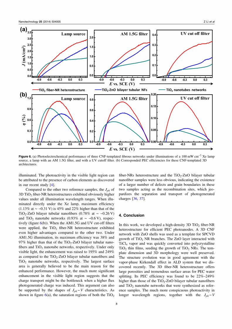
illuminated. The photoactivity in the visible light region canbe attributed to the presence of carbon elements as discoveredin our recent study [4].
Compared to the other two reference samples, the Jph of3D TiO2 fiber-NR heterostructures exhibited obviously highervalues under all illumination wavelength ranges. When illu-minated directly under the Xe lamp, maximum efficiency(1.13% at ∼ −0.31 V) is 45% and 22% higher than that of theTiO2-ZnO bilayer tubular nanofibers (0.78% at ∼ −0.26 V)and TiO2 nanotube networks (0.93% at ∼ −0.6 V), respec-tively (figure 6(b)). When the AM1.5G and UV cut-off filterswere applied, the TiO2 fiber-NR heterostructure exhibitedeven higher advantages compared to the other two. UnderAM1.5G illumination, its maximum efficiency was 38% and97% higher than that of the TiO2-ZnO bilayer tubular nano-fibers and TiO2 nanotube networks, respectively. Under onlyvisible light, the enhancement was raised to 195% and 249%as compared to the TiO2-ZnO bilayer tubular nanofibers andTiO2 nanotube networks, respectively. The largest surfacearea is generally believed to be the main reason for theenhanced performance. However, the much more significantenhancement in the visible light region suggests that thecharge transport might be the bottleneck when a higher fluxphotogenerated charge was induced. This argument can alsobe supported by the shapes of Jph−V characteristics. Asshown in figure 6(a), the saturation regions of both the TiO2
fiber-NRs heterostructure and the TiO2-ZnO bilayer tubularnanofiber samples were less obvious, indicating the existenceof a larger number of defects and grain boundaries in thesetwo samples acting as the recombination sites, which jeo-pardizes the separation and transport of photogeneratedcharges [36, 37].
4. Conclusion
In this work, we developed a high-density 3D TiO2 fiber-NRheterostructure for efficient PEC photoanodes. A 3D CNFnetwork with ZnO shells was used as a template for SPCVDgrowth of TiO2 NR branches. The ZnO layer interacted withTiCl4 vapor and was quickly converted into polycrystallineTiO2 thin films, seeding the growth of TiO2 NRs. The tem-plate dimension and 3D morphology were well preserved.The structure evolution was in good agreement with thevapor-phase Kirkendall effect in ALD system that we dis-covered recently. The 3D fiber-NR heterostructure offerslarge porosities and tremendous surface areas for PEC watersplitting. Its PEC efficiency was found to be 22%–249%higher than those of the TiO2-ZnO bilayer tubular nanofibersand TiO2 nanotube networks that were synthesized as refer-ence samples. The much more conspicuous photoactivity inlonger wavelength regions, together with the Jph−V
Figure 6. (a) Photoelectrochemical performance of three CNF-templated fibrous networks under illuminations of a 100 mW cm−2 Xe lampsource, a lamp with an AM 1.5G filter, and with a UV cutoff filter. (b) Corresponded PEC efficiencies for these CNF-templated 3Darchitectures.
8
Nanotechnology 25 (2014) 504005 Z Li et al
characteristics, suggest that charge transport might be theissue for the 3D fiber-NR heterostructure to further enhanceits PEC performance. This technique opens a new avenuetoward a cellulose-based nanomanufacturing technique,which holds great promise for large-area, low-cost, and greenfabrication of functional nanomaterials, as well as theirapplications in solar energy harvesting and conversion areas.
Acknowledgments
Research was primarily supported by the US Department ofEnergy (DOE), Office of Science, Basic Energy Sciences(BES), under Award # DE-SC0008711. CY thanks the sup-port of the National Science Foundation under Award CMMI-1233570.
References
[1] Maeda K and Domen K 2010 Photocatalytic water splitting:recent progress and future challenges J. Phys. Chem. Lett. 12655–61
[2] Su J, Feng X, Sloppy J D, Guo L and Grimes C A 2011Vertically aligned WO(3) nanowire arrays grown directly ontransparent conducting oxide coated glass: synthesis andphotoelectrochemical properties Nano Lett. 11 203–8
[3] Chen X, Shen S, Guo L and Mao S S 2010 Semiconductor-based photocatalytic hydrogen generation Chem. Rev. 1106503–70
[4] Li Z, Yao C, Yu Y, Cai Z and Wang X 2014 Highly efficientcapillary photoelectrochemical water splitting usingcellulose nanofiber-templated TiO2 photoanodes Adv. Mater.26 2262–7 110
[5] Yin W-J, Tang H, Wei S-H, Al-Jassim M M, Turner J andYan Y 2010 Band structure engineering of semiconductorsfor enhanced photoelectrochemical water splitting: the caseof TiO2 Phys. Rev. B 82 045106
[6] Hwang Y J, Boukai A and Yang P 2009 High density n-Si/n-TiO2 core/shell nanowire arrays with enhanced photoactivityNano Lett. 9 410–5
[7] Boettcher S W, Spurgeon J M, Putnam M C, Warren E L,Turner-Evans D B, Kelzenberg M D, Maiolo J R,Atwater H A and Lewis N S 2010 Energy-conversionproperties of vapor-liquid-solid-grown silicon wire-arrayphotocathodes Science 327 185–7
[8] Kim J-H, Yun T K, Bae J-Y and Ahn K-S 2009 Enhancedcarrier transport of N-doped TiO2 for photoelectrochemicalcells Japan. J. Appl. Phys. 48 120204
[9] Shen X, Sun B, Yan F, Zhao J, Zhang F, Wang S, Zhu X andLee S 2010 High-performance photoelectrochemical cellsfrom ionic liquid electrolyte in methyl-terminated siliconnanowire arrays ACS Nano 4 5869–76
[10] Shi J, Hara Y, Sun C, Anderson M A and Wang X 2011 Three-dimensional high-density hierarchical nanowire architecturefor high-performance photoelectrochemical electrodes NanoLett. 11 3413–9
[11] Wang F, Seo J H, Li Z, Kvit A V, Ma Z and Wang X 2014 Cl-doped ZnO nanowires with metallic conductivity and theirapplication for high-performance photoelectrochemicalelectrodes ACS Appl. Mater. Interfaces 6 1288–93
[12] Shi J and Wang X 2012 Hierarchical TiO2–Si nanowirearchitecture with photoelectrochemical activity under visiblelight illumination Energy Environ. Sci. 5 7918
[13] Cho I S, Chen Z, Forman A J, Kim D R, Rao P M,Jaramillo T F and Zheng X 2011 Branched TiO2 nanorodsfor photoelectrochemical hydrogen production Nano Lett. 114978–84
[14] Kargar A, Sun K, Jing Y, Choi C, Jeong H, Jung G Y,Jin S and Wang D 2013 3D branched nanowirephotoelectrochemical electrodes for efficient solar watersplitting ACS Nano 7 9407–15
[15] Cheng C and Fan H J 2012 Branched nanowires: synthesis andenergy applications Nano Today 7 327–43
[16] Luo J, Ma L, He T, Ng C F, Wang S, Sun H and Fan H J 2012TiO2/(CdS, CdSe, CdSeS) nanorod heterostructures andphotoelectrochemical properties J. Phys. Chem. C 11611956–63
[17] Zeng J, Li R, Liu S and Zhang L 2011 Fiber-like TiO2
nanomaterials with different crystallinity phases fabricatedvia a green pathway ACS Appl. Mater. Interfaces 32074–9
[18] Liu S, Tao D, Bai H and Liu X 2012 Cellulose-nanowhisker-templated synthesis of titanium dioxide/cellulosenanomaterials with promising photocatalytic abilitiesJ. Appl. Polym. Sci. 126 E282–90
[19] Moon R J, Martini A, Nairn J, Simonsen J and Youngblood J2011 Cellulose nanomaterials review: structure, propertiesand nanocomposites Chem. Soc. Rev. 40 3941–94
[20] Zhu H, Fang Z, Preston C, Li Y and Hu L 2014 Transparentpaper: fabrications, properties, and device applicationsEnergy Environ. Sci. 7 269
[21] Wang B 2008 Dispersion of cellulose nanofibers in biopolymerbased nanocomposites PhD Thesis University of Toronto,Toronto
[22] Serizawa T, Sawada T, Okura H and Wada M 2013 Hydrolyticactivities of crystalline cellulose nanofibersBiomacromolecules 14 613–7
[23] Jabbour L, Gerbaldi C, Chaussy D, Zeno E, Bodoardo S andBeneventi D 2010 Microfibrillated cellulose–graphitenanocomposites for highly flexible paper-like Li-ion batteryelectrodes J. Mater. Chem. 20 7344
[24] Jabbour L, Destro M, Gerbaldi C, Chaussy D, Penazzi N andBeneventi D 2012 Use of paper-making techniques for theproduction of Li-ion paper-batteries Nord. Pulp. Pap. Res. J.27 472–5
[25] Kemell M, Pore V, Ritala M, Leskela M and Linden M 2005Atomic layer deposition in nanometer-level replication ofcellulosic substances and preparation of photocatalytic TiO2/cellulose composites J. Am. Chem. Soc. 127 14178–9
[26] Ghadiri E, Taghavinia N, Zakeeruddin S M, Gratzel M andMoser J E 2010 Enhanced electron collection efficiency indye-sensitized solar cells based on nanostructured TiO2
hollow fibers Nano Lett. 10 1632–8[27] Wang H H, Zhu E W, Yang J Z, Zhou P P, Sun D P and
Tang W H 2012 Bacterial cellulose nanofiber-supportedpolyaniline nanocomposites with flake-shaped morphologyas supercapacitor electrodes J. Phys. Chem. C 11613013–9
[28] Yu Y, Yin X, Kvit A and Wang X 2014 Evolution of hollowTiO2 nanostructures via the Kirkendall effect driven bycation exchange with enhanced photoelectrochemicalperformance Nano Lett. 14 2528–35
[29] Qing Y, Sabo R, Cai Z and Wu Y 2012 Resin impregnation ofcellulose nanofibril films facilitated by water swellingCellulose 20 303–13
[30] Saito T, Hirota M, Tamura N, Kimura S, Fukuzumi H,Heux L and Isogai A 2009 Individualization of nano-sizedplant cellulose fibrils by direct surface carboxylation usingTEMPO catalyst under neutral conditionsBiomacromolecules 10 1992–6
[31] Korhonen J T, Hiekkataipale P, Malm J, Karppinen M,Ikkala O and Ras R H 2011 Inorganic hollow nanotube
9
Nanotechnology 25 (2014) 504005 Z Li et al
aerogels by atomic layer deposition onto nativenanocellulose templates ACS Nano 5 1967–74
[32] Shi J, Sun C, Starr M B and Wang X 2011 Growth of titaniumdioxide nanorods in 3D-confined spaces Nano Lett. 11 624–31
[33] Shi J A and Wang X D 2011 Growth of rutile titanium dioxidenanowires by pulsed chemical vapor deposition Cryst.Growth Des. 11 949–54
[34] Liu C, Tang J, Chen H M, Liu B and Yang P 2013 A fullyintegrated nanosystem of semiconductor nanowires fordirect solar water splitting Nano Lett. 13 2989–92
[35] Kargar A et al 2013 Tailoring n-ZnO/p-Si branched nanowireheterostructures for selective photoelectrochemical wateroxidation or reduction Nano Lett. 13 3017–22
[36] Morgan B J and Watson G W 2010 Intrinsic n-type defectformation in TiO2: a comparison of rutile and anatase fromGGA+U calculations J. Phys. Chem. C 114 2321–8
[37] Wu N, Wang J, Tafen de N, Wang H, Zheng J G, Lewis J P,Liu X, Leonard S S and Manivannan A 2010 Shape-enhanced photocatalytic activity of single-crystalline anataseTiO2 (101) nanobelts J. Am. Chem. Soc. 132 6679–85
10
Nanotechnology 25 (2014) 504005 Z Li et al


![eBook Production: A Templated Workflow [2013]](https://img.pdfslide.net/doc/110x75/5596c5c01a28ab51408b46a5/ebook-production-a-templated-workflow-2013.jpg)