Embed Size (px)
Citation preview

1C H A P T E R
General
TTTTThe history of cementing material is as old as thehistory of engineering construction. Some kind of
cementing materials were used by Egyptians,Romans and Indians in their ancient constructions. Itis believed that the early Egyptians mostly usedcementing materials, obtained by burning gypsum.Not much light has been thrown on cementingmaterial, used in the construction of the cities ofHarappa and Mohenjadaro.
An analysis of mortar from the Great Pyramidshowed that it contained 81.5 per cent calciumsulphate and only 9.5 per cent carbonate. The earlyGreeks and Romans used cementing materialsobtained by burning limestones. The remarkablehardness of the mortar used in early Romanbrickworks, some of which still exist, is presentingsufficient evidence of the perfection which the art ofcementing material had attained in ancient times.The superiority of Roman mortar has been attributedto thoroughness of mixing and long continuedramming.
The Greeks and Romans later became aware ofthe fact that certain volcanic ash and tuff, when
!!!!! General
!!!!! Early History of Modern Cement
!!!!! Manufacture of Portland Cement
!!!!! Wet Process
!!!!! Dry Process
!!!!! Chemical Composition
!!!!! Hydration of Cement
!!!!! Heat of Hydration
!!!!! Calcium Silicate Hydrates
!!!!! Calcium Hydroxide
!!!!! Calcium Aluminate Hydrates
!!!!! Structure of Hydrated Cement
!!!!! Transition Zone
!!!!! Water Requirements for Hydration
1
Cement
Modern Cement FactoryCourtesy : Grasim Industries Cement Division

2 """"" Concrete Technology
mixed with lime and sand yielded mortar possessing superior strength and better durabilityin fresh or salt water. Roman builders used volcanic tuff found near Pozzuoli village near MountVesuvius in Italy. This volcanic tuff or ash mostly siliceous in nature thus acquired the namePozzolana. Later on, the name Pozzolana was applied to any other material, natural orartificial, having nearly the same composition as that of volcanic tuff or ash found at Pozzuoli.The Romans, in the absence of natural volcanic ash, used powered tiles or pottery aspozzolana. In India. powered brick named surkhi has been used in mortar. The Indian practiceof through mixing and long continued ramming of lime mortar with or without the additionof Surkhi yielded strong and impervious mortar which confirmed the secret of superiority ofRoman mortar.
It is learnt that the Romans added blood, milk and lard to their mortar and concrete toachieve better workability. Haemoglobin is a powerful air-entraining agent and plasticizer,which perhaps is yet another reason for the durability of Roman structures. Probably they didnot know about the durability aspect but used them as workability agents. The cementingmaterial made by Romans using lime and natural or artificial Pozzolana retained its positionas the chief building material for all work, particularly, for hydraulic construction. Belidor, aprincipal authority in hydraulic construction, recommended an initimate mixture of tiles, stonechips, and scales from a black-smith’s forge, carefully ground, washed free from coal and dirt,dried and sifted and then mixed with fresh slaked lime for making good concrete.
When we come to more recent times, the most important advance in the knowledge ofcements, the forerunner to the discoveries and manufacture of all modern cements isundoubtedly the investigations carried out by John Smeaton. When he was called upon torebuild the Eddystone Light-house in 1756, he made extensive enquiries into the state of artexisting in those days and also conducted experiments with a view to find out the bestmaterial to withstand the severe action of sea water. Finally, he concluded that lime-stoneswhich contained considerable proportion of clayey matter yielded better lime possessingsuperior hydraulic properties. In spite of the success of Smeaton’s experiments, the use ofhydraulic lime made little progress, and the old practice of mixture of lime and pozzolanaremained popular for a long period. In 1976 hydraulic cement was made by calcining nodulesof argillaceous lime-stones. In about 1800 the product thus obtained was called Romancement. This type of cement was in use till about 1850 after which this was outdated byportland cement.
Early History of ModernCement
The investigations of L.J.Vicat led him to prepare anartif icial hydraulic l ime bycalcining an intimate mixtureof limestone and clay. Thisprocess may be regarded asthe leading knowledge to themanufacture of Portlandcement. James Frost alsopatented a cement of this kindin 1811 and established afactory in London district.
Joseph Aspdin’s first cement works, around 1823, at Kirkgate inWakefield, UK.
Courtesy : Ambuja Technical Literature

Cement """"" 3
The story of the invention of Portland cementis, however, attributed to Joseph Aspdin, a Leedsbuilder and bricklayer, even though similarprocedures had been adopted by other inventors.Joseph Aspdin took the patent of portland cementon 21st October 1824. The fancy name ofportland was given owing to the resemblance ofthis hardened cement to the natural stoneoccurring at Portland in England. In his processAspdin mixed and ground hard limestones andfinely divided clay into the form of slurry andcalcined it in a furnace similar to a lime kiln till theCO2 was expelled. The mixture so calcined wasthen ground to a fine powder. Perhaps, atemperature lower than the clinkeringtemperature was used by Aspdin. Later in 1845Isaac Charles Johnson burnt a mixture of clay andchalk till the clinkering stage to make bettercement and established factories in 1851.
In the early period, cement was used formaking mortar only. Later the use of cement wasextended for making concrete. As the use ofPortland cement was increased for makingconcrete, engineers called for consistently higherstandard material for use in major works.Association of Engineers, Consumers and CementManufacturers have been established to specifystandards for cement. The German standard specification for Portland cement was drawn in1877. The British standard specification was first drawn up in 1904. The first ASTM specificationwas issued in 1904.
In India, Portland cement was first manufactured in 1904 near Madras, by the South IndiaIndustrial Ltd. But this venture failed. Between 1912 and 1913, the Indian Cement Co. Ltd.,was established at Porbander (Gujarat) and by 1914 this Company was able to deliver about1000 tons of Portland cement. By 1918 three factories were established. Together they wereable to produce about 85000 tons of cement per year. During the First Five-Year Plan (1951-1956) cement production in India rose from 2.69 million tons to 4.60 million tons. By 1969the total production of cement in India was 13.2 million tons and India was then occupyingthe 9th place in the world, with the USSR producing 89.4 million tonnes and the USAproducing 70.5 million tonnes1.1. Table 1.1 shows the Growth of Cement Industry throughPlans.
Prior to the manufacture of Portland cement in India, it was imported from UK and onlya few reinforced concrete structures were built with imported cement. A three storeyedstructure built at Byculla, Bombay is one of the oldest RCC structures using Portland cementin India. A concrete masonry building on Mount Road at Madras (1903), the har-ki-paharibridge at Haridwar (1908) and the Cotton Depot Bombay, then one of the largest of its kindin the world (1922) are some of the oldest concrete structures in India.1.2
Oldest surviving kiln, northeast Kent, UK,(1847AD).
Courtesy : Ambuja Technical Literature

4 """"" Concrete Technology
Table 1.1. Growth of Cement Industry through Plans
Five Year At the Capacity %age Production %age GDPPlan end of (*) Growth (*) Growth Growth
the Year Cement
Pre Plan 50-51 3.28 2.20
I Plan 55-56 5.02 4.60
II Plan 60-61 9.30 13.12 7.97 11.62 7.1
III Plan 65-66 12.00 5.23 10.97 6.60 3.4
There were Annual Plans for 1966-67, 67-68 and 68-69
IV Plan 73.74 19.76 10.49 14.66 5.97 4.6
V Plan 78-79 22.58 2.70 19.42 5.78 5.5
VI Plan 84-85 42.00 13.22 30.13 9.18 3.8
VII Plan 89-90 61.55 7.94 45.41 8.55 6.9
Annual 90-91 64.36 0.90 48.90 1.49 5.4
Plans 91-92 66.56 3.42 53.61 9.63 5.3
VIII Plan 92-93 70.19 5.45 54.08 0.88 4.1
93-94 76.88 9.53 57.96 7.17 6.0
94-95 83.69 8.86 62.35 7.57 7.2
95-96 97.25 16.20 69.57 11.58 7.1
96-97 105.25 8.23 76.22 9.56 6.8
IX Plan 97-98 109.30 3.85 83.16 9.10 5.2
(*) Includes mini cement plantsSource: Indian Cement Industry Emerging Trends — P. Parthsarathy and S.M. Chakravarthy
Table 1.2. Per Capita Cement Consumption of Selected Countries of theWorld (1982, 1994 and 1997)
Country Per Capita Cement Consumption (Kg.)
1982 1994 1997
USA 256 328 347China 92 333 388Taiwan 590 1285 966Japan 617 642 622Malaysia 290 512 831Thailand 132 491 595Argentina 198 184 145 (1996)Brazil 201 165 240Venezuela 356 222 169 (1996)Turkey 251 436 511Wor ld 1 8 8 2 4 1 252 (1995)
India 78 kg (1996), 82 kg (1997)

Cement """"" 5
The perusal of table 1.2 shows that per capita cement consumption in India is much lessthan world average. Considerable infrastructural development is needed to build modernIndia. Production of more cement, knowledge and economical utilisation of cement is theneed of the day.
The early scientific study of cements did not reveal much about the chemical reactionsthat take place at the time burning. A deeper study of the fact that the clayey constituents oflimestone are responsible for the hydraulic properties in lime (as established by John Smeaton)was not taken for further research. It may be mentioned that among the earlier cementtechnologists, Vicat, Le Chatelier and Michaelis were the pioneers in the theoretical andpractical field.
Systematic work on the composition and chemical reaction of Portland cement was firstbegun in the United States. The study on setting was undertaken by the Bureau of Standardsand since 1926 much work on the study of Portland cement was also conducted by thePortland Cement Association, U.K. By this time, the manufacture and use of Portland cementhad spread to many countries. Scientific work on cements and fundamental contributions tothe chemistry of Portland cements were carried out in Germany, Italy, France, Sweden, Canadaand USSR, in addition to Britain and USA. In Great Britain with the establishment of BuildingResearch Station in 1921 a systematic research programme was undertaken and many majorcontributions have been made. Early literatures on the development and use of Portlandcements may be found in the Building Science Abstracts published by Building ResearchStation U.K. since 1928, “Documentation Bibliographique” issued quarterly since 1948 inFrance and “Handbuch der Zement Literature” in Germany.
Manufacture of Portland CementThe raw materials required for manufacture of Portland cement are calcareous materials,
such as limestone or chalk, and argillaceous material such as shale or clay. Cement factoriesare established where these raw materials are available in plenty. Cement factories have comeup in many regions in India, eliminating the inconvenience of long distance transportation ofraw and finished materials.
The process of manufacture of cement consists of grinding the raw materials, mixingthem intimately in certain proportions depending upon their purity and composition andburning them in a kiln at a temperature of about 1300 to 1500°C, at which temperature, thematerial sinters and partially fuses to form nodular shaped clinker. The clinker is cooled andground to fine powder with addition of about 3 to 5% of gypsum. The product formed byusing this procedure is Portland cement.
There are two processes known as “wet” and “dry” processes depending upon whetherthe mixing and grinding of raw materials is done in wet or dry conditions. With a little changein the above process we have the semi-dry process also where the raw materials are grounddry and then mixed with about 10-14 per cent of water and further burnt to clinkeringtemperature.
For many years the wet process remained popular because of the possibility of moreaccurate control in the mixing of raw materials. The techniques of intimate mixing of rawmaterials in powder form was not available then. Later, the dry process gained momentumwith the modern development of the technique of dry mixing of powdered materials usingcompressed air. The dry process requires much less fuel as the materials are already in a drystate, whereas in the wet process the slurry contains about 35 to 50 per cent water. To dry

6 """"" Concrete Technology
the slurry we thus require more fuel. In India most of the cement factories used the wetprocess. Recently a number of factories have been commissioned to employ the dry processmethod. Within next few years most of the cement factories will adopt dry process system.
In the wet process, the limestone brought from the quarries is first crushed to smallerfragments. Then it is taken to a ball or tube mill where it is mixed with clay or shale as the casemay be and ground to a fine consistency of slurry with the addition of water. The slurry is aliquid of creamy consistency with water content of about 35 to 50 per cent, wherein particles,crushed to the fineness of Indian Standard Sieve number 9, are held in suspension. The slurryis pumped to slurry tanks or basins where it is kept in an agitated condition by means ofrotating arms with chains or blowing compressed air from the bottom to prevent settling oflimestone and clay particles. The composition of the slurry is tested to give the requiredchemical composition and corrected periodically in the tube mill and also in the slurry tankby blending slurry from different storage tanks. Finally, the corrected slurry is stored in the finalstorage tanks and kept in a homogeneous condition by the agitation of slurry.
The corrected slurry is sprayed on to the upper end of a rotary kiln against hot heavyhanging chains. The rotary kiln is an important component of a cement factory. It is a thicksteel cylinder of diameter anything from 3 metres to 8 metres, lined with refractory materials,mounted on roller bearings and capable of rotating about its own axis at a specified speed.The length of the rotary kiln may vary anything from 30 metres to 200 metres. The slurry onbeing sprayed against a hot surface of flexible chain loses moisture and becomes flakes. Theseflakes peel off and fall on the floor. The rotation of the rotary kiln causes the flakes to movefrom the upper end towards the lower end of the kiln subjecting itself to higher and highertemperature. The kiln is fired from the lower end. The fuel is either powered coal, oil or naturalgass. By the time the material rolls down to the lower end of the rotary kiln, the dry material

Cement """"" 7
Fig. 1.1. Diagrammatic representation of the dry process of manufacure of cement.(Courtesy : Grasim Industries Cement Division)

8 """"" Concrete Technology
A view of Limestone quarry, raw material preparation : The prime raw material limestone after blastingin mines is broken into big boulders. Then it is transported by dumpers, tippers to limestone crusherwhere it is crushed to 15 to 20 mm size.
STACKER FOR CRUSHEDLIMESTONE
RECLAIMER FOR CRUSHEDLIMESTONE
After crushing, the crushedlimestone is piledlongitudinally by anequipment called stacker.The stacker depositslimestone longitudinally inthe form of a pile. The pile isnormally 250 to 300 m longand 8-10 m height. Thereclaimer cuts the pilevertically, simultaneouslyfrom top to bottom to ensurehomogenization oflimestone.
Reclaimer for homogenization of crushed limestone.

Cement """"" 9
undergoes a series of chemical reactions until finally, in the hottest part of the kiln, where thetemperature is in the order of 1500°C, about 20 to 30 per cent of the materials get fused.Lime, silica and alumina get recombined. The fused mass turns into nodular form of size 3 mmto 20 mm known as clinker. The clinker drops into a rotary cooler where it is cooled undercontrolled conditions The clinker is stored in silos or bins. The clinker weighs about 1100 to1300 gms per litre. The litre weight of clinker indicates the quality of clinker.
The cooled clinker is then ground in a ball mill with the addition of 3 to 5 per cent ofgypsum in order to prevent flash-setting of the cement. A ball mill consists of severalcompartments charged with progressively smaller hardened steel balls. The particles crushedto the required fineness are separated by currents of air and taken to storage silos from wherethe cement is bagged or filled into barrels for bulk supply to dams or other large work sites.
In the modern process of grinding, the particle size distribution of cement particles aremaintained in such a way as to give desirable grading pattern. Just as the good grading ofaggregates is essential for making good concrete, it is now recognised that good gradingpattern of the cement particles is also important.
The Fig. 1.1 shows the flow diagram of dry process of manufacture of cement.
Dry ProcessIn the dry and semi-dry process the raw materials are crushed dry and fed in correct
proportions into a grinding mill where they are dried and reduced to a very fine powder. Thedry powder called the raw meal is then further blended and corrected for its right compositionand mixed by means of compressed air. The aerated powder tends to behave almost like liquidand in about one hour of aeration a uniform mixture is obtained.
The blended meal is further sieved and fed into a rotating disc called granulator. Aquantity of water about 12 per cent by wright is added to make the blended meal into pellets.This is done to permit air flow for exchange of heat for further chemical reactions andconversion of the same into clinker further in the rotary kiln.
The equipments used in the dry process kiln is comparatively smaller. The process is quiteeconomical. The total consumption of coal in this method is only about 100 kg whencompared to the requirement of about 350 kg for producing a ton of cement in the wetprocess. During March 1998, in India, there were 173 large plants operating, out of which49 plants used wet process, 115 plants used dry process and 9 plants used semi-dry process.
Since the time of partial liberalisation of cement industry in India (1982), there has beenan upgradation in the quality of cement. Many cement companies upgraded their plants bothin respect of capacity and quality. Many of the recent plants employed the best equipments,such as cross belt analyser manufactured by Gamma-Metrics of USA to find the compositionof limestone at the conveyor belts, high pressure twin roller press, six stage preheater,precalciner and vertical roller mill. The latest process includes stacker and reclaimer, on-line X-ray analyser, Fuzzy Logic kiln control system and other modern process control. In one of therecently built cement plant at Reddypalayam near Trichy, by Grasim Indistries, employed Robotfor automatic collection of hourly samples from 5 different places on the process line and helpanalyse the ame, throughout 24 hours, untouched by men, to avoid human errors in qualitycontrol. With all the above sophisticated equipments and controls, consistent quality of clinkeris produced.
The methods are commonly employed for direct control of quality of clinker. The firstmethod involves reflected light optical microscopy of polished and etched section of clinker,

10 """"" Concrete Technology
RAW MILL
The proportioned raw materials are transported by belt conveyor to Raw Mill for grinding intopowder form before burning.
RAW MEAL SILO
After grinding, the powdered raw mix, isstored in a raw meal-silo where blendingtakes place. Blending is done by injectingcompressed air. Generally blending ratiois 1:10. This powder material (Raw meal) isfed to the kiln for burning.

Cement """"" 11
ROBO LABConsists of automatic sampling and sending station located at different locations in the plant. Samplesare being sent through pneumatic tubes to Robo lab. This avoids human error in sampling and ensuresaccurate quality in semi finished and finished products. 1st of its kind in India has been used at GrasimCement plant at Reddypalayam.
Robot receiving samples.
12 """"" Concrete Technology
Close circuit grinding technology is most moderngrinding system for raw mix as well as for clinkergrinding. The systems are in compound mode and areequipped with high efficiency Roller press andseparators. The above mentioned system enables tomaintain low power consumption for grinding as well asnarrow particle size distribution. With this circuit, it ispossible to manufacture higher surface area of productas per customers, requirement.
Electronic packers: it has continuousweighing system and it ensures that thebags separating from the nozzles haveaccurate weight of cement. The weight offilled bag is also displayed on the packer.
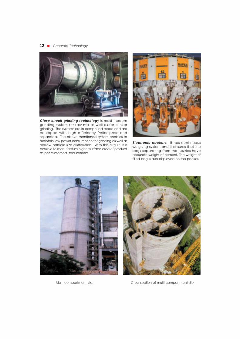
Multi-compartment silo. Cross section of multi-compartment silo.

Cement """"" 13
Jumbo bag transportation.
Jumbo bag packing.
followed by point count of areasoccupied by various compounds. Thesecond method, which is also applicableto powdered cement, involves X-raydiffraction of powder specimen.Calibration curves based on knownmixtures of pure compounds, help toestimate the compound composition. Asa rough and ready method, litre weight(bulk density) of clinker is made use of toascertain the quality. A litre weight ofabout 1200 gms. is found to besatisfactory.
It is important to note that thestrength properties of cement are
considerably influenced by the cooling rate of clinker. This fact has of late attracted theattention of both the cement manufacturers and machinery producers. The experimentalresults reported by Enkegaard are shown in table 1.3.
Table 1.3. Influence of Rate of Cooling on Compressive Strength1.3
Type of cement Cooling Compressive Strength MPa
conditions 3 days 7 days 28 days
Quick 9.9 15.3 26
Moderate 9.7 21.0 27
Normal Cement Slow 9.7 19.3 24
Very slow 8.7 18.7 23
High early Quick 10.2 18.8 29
strength Moderate 14.2 26.7 33
cement Slow 10.2 21.0 29
Very Slow 9.1 18.1 28

14 """"" Concrete Technology
It can be seen from the table that a moderate rate of cooling of clinker in the rotary coolerwill result in higher strength. By moderate cooling it is implied that from about 1200°C, theclinker is brought to about 500°C in about 15 minutes and from the 500°C the temperatureis brought down to normal atmospheric temperature in about 10 minutes.
The rate of cooling influences the degree of crystallisation, the size of the crystal and theamount of amorphous materials present in the clinker. The properties of this amorphousmaterial for similar chemical composition will be different from the one which is crystallined.
Chemical CompositionThe raw materials used for the manufacture of cement consist mainly of lime, silica,
alumina and iron oxide. These oxides interact with one another in the kiln at high temperatureto form more complex compounds. The relative proportions of these oxide compositions areresponsible for influencing the various properties of cement; in addition to rate of cooling andfineness of grinding. Table 1.4 shows the approximate oxide composition limits of ordinaryPortland cement.
Table 1.4. Approximate Oxide Composition Limits of Ordinary PortlandCement
Oxide Per cent content
CaO 60–67
SiO2 17–25
Al2O3 3.0–8.0
Fe2O3 0.5–6.0
MgO 0.1–4.0
Alkalies (K2O, Na2O) 0.4–1.3
SO3 1.3–3.0
Indian standard specification for 33 grade cement, IS 269-1989, specifies the followingchemical requirements:
(a) Ratio of percentage of lime to percentage of silica, alumina and iron oxide; knownas Lime Saturation Factor, when calculated by the formula
CaO 0.7 SO
2.8 SiO 1.2 Al O 0.65 Fe O2 2 3 2 3
−+ +
3 Not greater than 1.02 and not less than 0.66
(b) Ratio of percentage of alumina to that of iron oxide Not less tan 0.66
(c) Weight of insoluble residue Not more than 4 per cent
(d) Weight of magnesia Not more than 6 per cent
(e) Total sulphur content, calculated as sulphuric Not more than 2.5%when
anhydride (SO3) C3A is 5% or less. Notmore than 3%, when C3Ais more than 5%
(f ) Total loss on ignition Not more than 5 per cent

Cement """"" 15
As mentioned earlier the oxides persent in the raw materials when subjected to highclinkering temperature combine with each other to form complex compounds. Theidentification of the major compounds is largely based on R.H. Bogue’s work and hence it iscalled “Bogue’s Compounds”. The four compounds usually regarded as major compounds arelisted in table 1.5.
Table 1.5. Bogue’s Compounds
Name of Compound Formula Abbreviated Formula
Tricalcium silicate 3 CaO.SiO2 C3S
Dicalcium silicate 2 CaO.Sio2 C2S
Tricalcium aluminate 3 Cao.Al2O3 C3A
Tetracalcium aluminoferrite 4 CaO.Al2O3.Fe2O3 C4AF
It is to be noted that for simplicity’s sake abbreviated notations are used. C stands for CaO,S stands for SiO2, A for Al2O3, F for Fe2O3 and H for H2O.
The equations suggested by Bogue for calculating the percentages of major compoundsare given below.
C3S = 4.07 (CaO) – 7.60 (SiO2) – 6.72 (Al2O3) – 1.43 (Fe2O3) – 2.85 (SO3)
C2S = 2.87 (SiO2) – 0.754 (3CaO.SiO2)
C3A = 2.65 (Al2O3) – 1.69 (Fe2O3)
C4AF= 3.04 (Fe2O3)
The oxide shown within the brackets represents the percentage of the same in the rawmaterials.
Table 1.6. The Oxide Composition of a Typical Portland Cement and theCorrosponding Calculated Compound Composition.
Oxide composition Calculated compound composition Per cent using Bogue’s equation per cent
CaO 63 C3S 54.1
SiO2 20 C2S 16.6
Al2O3 6 C3A 10.8
Fe2O3 3 C4AF 9.1
MgO 1.5
SO2 2
K2O
Na2O
In addition to the four major compounds, there are many minor compounds formed inthe kiln. The influence of these minor compounds on the properties of cement or hydratedcompounds is not significant. Two of the minor oxides namely K2O and Na2O referred to asalkalis in cement are of some importance. This aspect will be dealt with later when discussingalkali-aggregate reaction. The oxide composition of typical Portland cement and thecorresponding calculated compound composition is shown in table 1.6.
1.0
16 """"" Concrete Technology
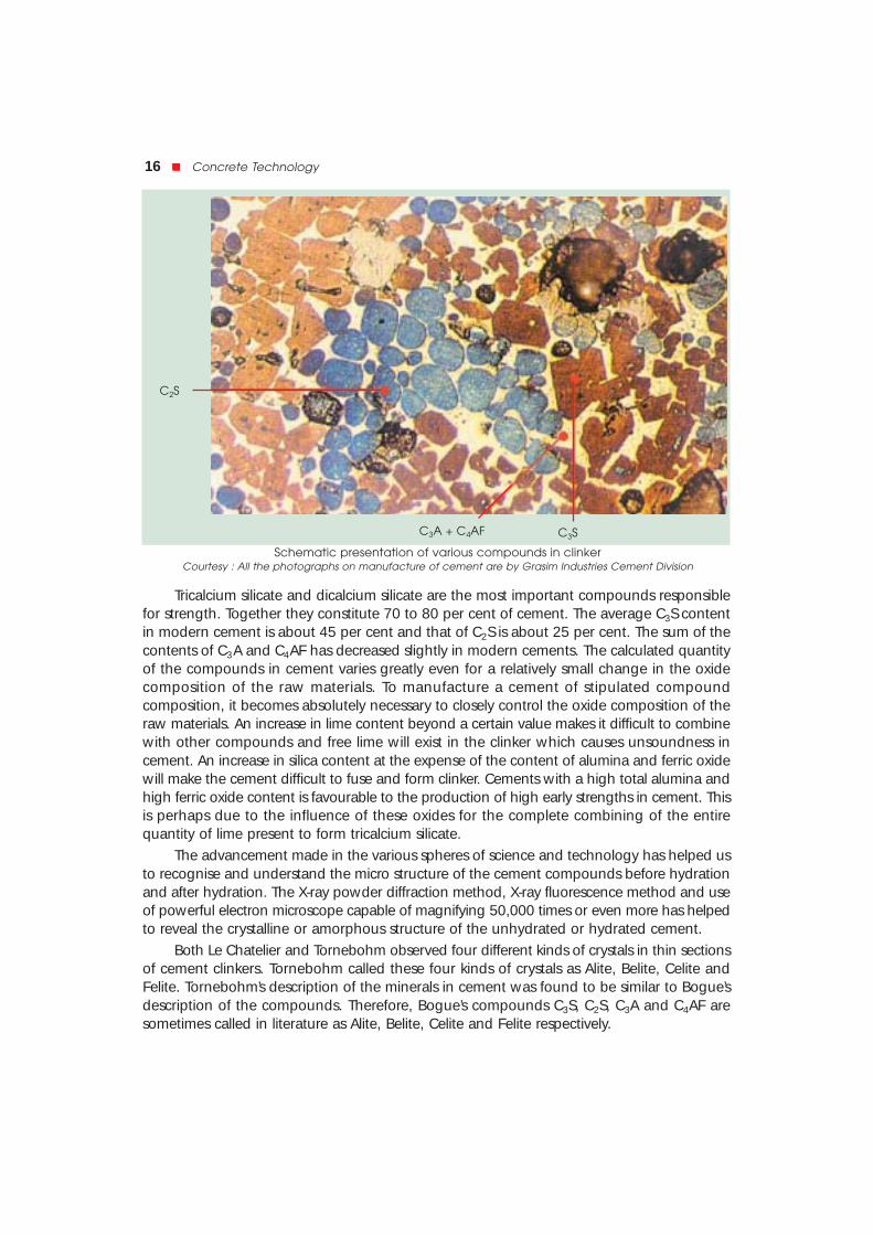
Tricalcium silicate and dicalcium silicate are the most important compounds responsiblefor strength. Together they constitute 70 to 80 per cent of cement. The average C3S contentin modern cement is about 45 per cent and that of C2S is about 25 per cent. The sum of thecontents of C3A and C4AF has decreased slightly in modern cements. The calculated quantityof the compounds in cement varies greatly even for a relatively small change in the oxidecomposition of the raw materials. To manufacture a cement of stipulated compoundcomposition, it becomes absolutely necessary to closely control the oxide composition of theraw materials. An increase in lime content beyond a certain value makes it difficult to combinewith other compounds and free lime will exist in the clinker which causes unsoundness incement. An increase in silica content at the expense of the content of alumina and ferric oxidewill make the cement difficult to fuse and form clinker. Cements with a high total alumina andhigh ferric oxide content is favourable to the production of high early strengths in cement. Thisis perhaps due to the influence of these oxides for the complete combining of the entirequantity of lime present to form tricalcium silicate.
The advancement made in the various spheres of science and technology has helped usto recognise and understand the micro structure of the cement compounds before hydrationand after hydration. The X-ray powder diffraction method, X-ray fluorescence method and useof powerful electron microscope capable of magnifying 50,000 times or even more has helpedto reveal the crystalline or amorphous structure of the unhydrated or hydrated cement.
Both Le Chatelier and Tornebohm observed four different kinds of crystals in thin sectionsof cement clinkers. Tornebohm called these four kinds of crystals as Alite, Belite, Celite andFelite. Tornebohm’s description of the minerals in cement was found to be similar to Bogue’sdescription of the compounds. Therefore, Bogue’s compounds C3S, C2S, C3A and C4AF aresometimes called in literature as Alite, Belite, Celite and Felite respectively.
C3S
C2S
C3A + C4AF
Schematic presentation of various compounds in clinkerCourtesy : All the photographs on manufacture of cement are by Grasim Industries Cement Division

Cement """"" 17
Cement and hydration of Portland cement can be schematically represented as below:
Hydration of CementAnhydrous cement does not bind fine and coarse aggregate. It acquires adhesive
property only when mixed with water. The chemical reactions that take place between cementand water is referred as hydration of cement.
The chemistry of concrete is essentially the chemistry of the reaction between cement andwater.On account of hydration certain products are formed. These products are importantbecause they have cementing oradhesive value. The quality, quantity,continuity, stability and the rate offormation of the hydration products areimportant.
Anhydrous cement compoundswhen mixed with water, react witheach other to form hydratedcompounds of very low solubility. Thehydration of cement can be visualisedin two ways. The first is “throughsolution” mechanism. In this the cementcompounds dissolve to produce asupersaturated solution from whichdifferent hydrated products getprecipitated. The second possibility is

18 """"" Concrete Technology
that water attacks cement compounds in the solid state converting the compounds intohydrated products starting from the surface and proceeding to the interior of the compoundswith time. It is probable that both “through solution” and “solid state” types of mechanism mayoccur during the course of reactions between cement and water. The former mechanism maypredominate in the early stages of hydration in view of large quantities of water beingavailable, and the latter mechanism may operate during the later stages of hydration.
Heat of HydrationThe reaction of cement with water is exothermic. The reaction liberates a considerable
quantity of heat. This liberation of heat is called heat of hydration. This is clearly seen if freshlymixed cement is put in a vaccum flask and the temperature of the mass is read at intervals.The study and control of the heat of hydration becomes important in the construction ofconcrete dams and other mass concrete constructions. It has been observed that thetemperature in the interior of large mass concrete is 50°C above the original temperature ofthe concrete mass at the time of placing and this high temperature is found to persist for aprolonged period. Fig 1.2 shows the pattern of liberation of heat from setting cement1.4 andduring early hardening period.
On mixing cement with water, a rapid heat evolution, lasting a few minutes, occurs. Thisheat evolution is probably due to the reaction of solution of aluminates and sulphates(ascending peak A). This initial heat evolution ceases quickly when the solubility of aluminateis depressed by gypsum. (decending peak A). Next heat evolution is on account of formationof ettringite and also may be due to the reaction of C3S (ascending peak B). Refer Fig. 1.2.
Different compounds hydrate at different rates and liberate different quantities of heat.Fig. 1.3 shows the rate of hydration of pure compounds. Since retarders are added to controlthe flash setting properties of C3A, actually the early heat of hydration is mainly contributedfrom the hydration of C3S. Fineness of cement also influences the rate of development of heatbut not the total heat. The total quantity of heat generated in the complete hydration willdepend upon the relative quantities of the major compounds present in a cement.
Analysis of heat of hydration data of large number of cements, Verbec and Foster1.5
computed heat evolution of four major compounds of cement. Table 1.7. shows the heatsof hydration of four compounds.

Cement """"" 19
Table 1.7. Heat of Hydration1.5
Compound Heat of hydration at the given age (cal/g)
3 days 90 days 13 years
C3S 58 104 122
C2S 12 42 59
C3A 212 311 324
C4AF 69 98 102
Since the heat of hydration of cement is an additive property, it can be predicted froman expression of the type H = aA + bB + cC + dD
Where H represents the heat of hydration, A, B, C, and D are the percentage contentsof C3S, C2S, C3A and C4AF. and a, b, c and d are coefficients representing the contribution of1 per cent of the corresponding compound to the heat of hydration.
Normal cement generally produces 89-90 cal/g in 7 days and 90 to 100 cal/g in 28 days.
The hydration process is not an instantaneous one. The reaction is faster in the earlyperiod and continues idenfinitely at a decreasing rate. Complete hydration cannot be obtainedunder a period of one year or more unless the cement is very finely ground and reground withexcess of water to expose fresh surfaces at intervals. Otherwise, the product obtained showsunattacked cores of tricalcium silicate surrounded by a layer of hydrated silicate, which beingrelatively impervious to water, renders further attack slow. It has been observed that after 28days of curing, cement grains have been found to have hydrated to a depth of only 4µ. Ithas also been observed that complete hydration under normal condition is possible only forcement particles smaller than 50µ.
A grain of cement may contain many crystals of C3S or others. The largest crystals of C3Sor C2S are about 40µ. An average size would be 15-20µ. It is probable that the C2S crystalspresent in the surface of a cement grain may get hydrated and a more reactive compoundlike C3S lying in the interior of a cement grain may not get hydrated.
The hydrated product of the cement compound in a grain of cement adheres firmly tothe unhydrated core in the grains of cement. That is to say unhydrated cement left in a grainof cement will not reduce the strength of cement mortar or concrete, as long as the productsof hydration are well compacted. Abrams obtained strength of the order of 280 MPa usingmixes with a water/cement ratio as low as 0.08. Essentially he has applied tremendouspressure to obtain proper compaction of such a mixture. Owing to such a low water/cementratio, hydration must have been possible only at the surface of cement grains, and aconsiderable portion of cement grains must have remained in an unhydrated condition.
The present day High Performance concrete is made with water cement ratio in theregion of 0.25 in which case it is possible that a considerable portion of cement grain remainsunhydrated in the core. Only surface hydration takes place. The unhydrated core of cementgrain can be deemed to work as very fine aggregates in the whole system.
Calcium Silicate HydratesDuring the course of reaction of C3S and C2S with water, calcium silicate hydrate,
abbreviated C-S-H and calcium hydroxide, Ca(OH)2 are formed. Calcium silicate hydrates arethe most important products. It is the essence that determines the good properties of concrete.

20 """"" Concrete Technology
It makes up 50-60 per cent of the volume of solids in a completely hydrated cement paste.The fact that term C-S-H is hyphenated signifies that C-S-H is not a well defined compound.The morphology of C-S-H shows a poorly crystalline fibrous mass.
It was considered doubtful that the product of hydration of both C3S and C2S results inthe formation of the same hydrated compound. But later on it was seen that ultimately thehydrates of C3S and C2S will turn out to be the same. The following are the approximateequations showing the reactions of C3S and C2S with water.
2 (3 CaO.SiO2) + 6H2O → 3 CaO.2 SiO2. 3H2O + 3Ca(OH)2
or it can be written as 2C3S + 6H → C3S2H3 + 3Ca(OH)2The corresponding weights involved are
100 + 24 → 75 + 49.
Similarly, 2 (2 CaO.SiO2) + 4 H2O→ 3Cao.2 SiO2. 3H2O + Ca(OH)2or it can be written as
2 C2S + 4 H → C3S2H3 + Ca (OH)2The corresponding weights involved are
100 + 21 → 99 + 22
However, the simple equations given above do not bring out the complexities of the actualreactions.
It can be seen that C3S produces a comparatively lesser quantity of calcium silicatehydrates and more quantity of Ca(OH)2 than that formed in the hydration of C2S. Ca(OH)2 isnot a desirable product in the concrete mass, it is soluble in water and gets leached outmaking the concrete porous, particularly in hydraulic structures. Under such conditions it isuseful to use cement with higher percentage of C2S content.
C3S readily reacts with water and produces more heat of hydration. It is responsible forearly strength of concrete. A cement with more C3S content is better for cold weatherconcreting. The quality and density of calcium silicate hydrate formed out of C3S is slightlyinferior to that formed by C2S. The early strength of concrete is due to C3S.
C2S hydrates rather slowly. It is responsible for the later strength of concrete. It producesless heat of hydration. The calcium silicate hydrate formed is rather dense and its specificsurface is higher. In general, the quality of the proudct of hydration of C2S is better than thatproduced in the hydration of C3S. Fig 1.4 shows the development of strength of purecompounds.
Calcium HydroxideThe other products of hydration of C3S and C2S is calcium hydroxide. In contrast to the
C-S-H, the calcium hydroxide is a compound with a distinctive hexagonal prism morphology.It constitutes 20 to 25 per cent of the volume of solids in the hydrated paste. The lack ofdurability of concrete, is on account of the presence of calcium hydroxide. The calciumhydroxide also reacts with sulphates present in soils or water to form calcium sulphate whichfurther reacts with C3A and cause deterioration of concrete. This is known as sulphate attack.To reduce the quantity of Ca(OH)2 in concrete and to overcome its bad effects by convertingit into cementitious product is an advancement in concrete technology. The use of blending

Cement """"" 21
materials such as fly ash, silica fume and such other pozzolanic materials are the steps toovercome bad effect of Ca(OH)2 in concrete. This aspect will be dealt in greater detail later.
The only advantage is that Ca(OH)2, being alkaline in nature maintain pH value around13 in the concrete which resists the corrosion of reinforcements.
Calcium Aluminate HydratesThe hydration of aluminates has been the subject of numerous investigations, but there
is still some uncertainty about some of the reported products. Due to the hydration of C3A ,a calcium aluminate system CaO – Al2O3 – H2O is formed. The cubic compound C3AH6 isprobably the only stable compound formed which remains stable upto about 225°C.
The reaction of pure C3A withwater is very fast and this may leadto flash set. To prevent this flash set,gypsum is added at the time ofgrinding the cement clinker. Thequantity of gypsum added has abearing on the quantity of C3 Apresent.
The hydrated aluminates do notcontribute anything to the strengthof concrete. On the other hand, theirpresence is harmful to the durabilityof concrete particularly where theconcrete is likely to be attacked bysulphates. As it hydrates very fast itmay contribute a little to the earlystrength.
On hydration, C4AF is believedto form a system of the form CaO – Fe2O3 – H2O. A hydrated calcium ferrite of the form C3FH6
is comparatively more stable. This hydrated product also does not contribute anything to thestrength. The hydrates of C4AF show a comparatively higher resistance to the attack ofsulphates than the hydrates of calcium aluminate.
From the standpoint of hydration, it is convenient to discuss C3A and C4AF together,because the products formed in the presence of gypsum are similar. Gypsum and alkalies gointo solution quickly and the solubility of C3A is depressed. Depending upon the concentrationof aluminate and sulphate ions in solution, the pricipitating crystalline product is either thecalcium aluminate trisulphate hydrate (C6A S 3H32) or calcium aluminate monosulhphatehydrate (C4A S H18). The calcium aluminate trisulphate hydrate is known as ettringite.
Ettringite is usually the first to hydrate and crystallise as short prismatic needle on accountof the high sulphate/aluminate ratio in solution phase during the first hour of hydration. Whensulphate in solution gets depleted, the aluminate concentration goes up due to renewedhydration of C3A and C4AF. At this stage ettringite becomes unstable and is graduallyconverted into mono-sulphate, which is the final product of hydration of portland cementscontaining more than 5 percent C3A.
The amount of gypsum added has significant bearing on the quantity of aluminate inthe cement. The maintenance of aluminate-to-sulphate ratio balance the normal setting

22 """"" Concrete Technology
behaviour of cement paste. The various setting phenomena affected by an imbalance in theA/ S ratio is of practical significance in concrete technology.
Many theories have been put forward to explain what actually is formed in the hydrationof cement compounds with water. It has been said earliiar that product consisting of(CaO.SiO2.H2O) and Ca(OH)2 are formed in the hydration of calcium silicates. Ca(OH)2 is anunimportant product, and the really significant product is (CaO.SiO2.H2O). For simplicity’s sakethis product of hydration is sometime called tobermorite gel because of its structural similarityto a naturally occurring mineral tobermorite. But very commonly the product of hydration isreferred to as C – S – H gel.
It may not be exactly correct to call the product of hydrations as gel. Le chatelier identifiedthe products as crystalline in nature and put forward his crystalline theory. He explained thatthe precipitates resemble crystals interlocked with each other. Later on Michaelis put forwardhis colloidal theory wherein he considered the precipitates as colloidal mass, gelatinous innature. It is agreed that an element of truth exists in both these theories. It is accepted nowthat the product of hydration is more like gel, consisting of poorly formed, thin, fibrous crystalsthat are infinitely small. A variety of transitional forms are also believed to exist and the wholeis seen as bundle of fibres, a fluffy mass with a refractive index of 1.5 to 1.55, increasing withage.
Since the gel consists of crystals, it is porous in nature. It is estimated that the porosity ofgel is to the extent of 28%. The gel pores are filled with water. The pores are so small that thespecific surface of cement gel is of the order of 2 million sq. cm. per gm. of cement. Theporosity of gel can be found out by the capillary condensation method or by the mercuryporosimetry method.
Structure of Hydrated CementTo understand the behaviour of concrete, it is necessary to acquaint ourselves with the
structure of hydrated hardened cement paste. If the concrete is considered as two phasematerial, namely, the paste phase and the aggregate phase, the understanding of the pastephase becomes more important as it influences the behaviour of concrete to a much greaterextent. It will be discussed later that the strength, the permeability, the durability, the dryingshrinkage, the elastic properties, the creep and volume change properties of concrete is greatlyinfluenced by the paste structure. The aggregate phase though important, has lesser influenceon the properties of concrete than the paste phase. Therefore, in our study to understandconcrete, it is important that we have a deep understanding of the structure of the hydratedhardened cement paste at a phenomenological level.
Transition ZoneConcrete is generally considered as two phase material i.e., paste phase and aggregates
phase. At macro level it is seen that aggregate particles are dispersed in a matrix of cementpaste. At the microscopic level, the complexities of the concrete begin to show up, particularlyin the vicinity of large aggregate particles. This area can be considered as a third phase, thetransition zone, which represents the interfacial region between the particles of coarseaggregate and hardened cement paste. Transition zone is generally a plane of weakness and,therefore, has far greater influence on the mechanical behaviour of concrete.
Although transition zone is composed of same bulk cement paste, the quality of pastein the transition zone is of poorer quality. Firstly due to internal bleeding, water accumulatebelow elongated, flaky and large pieces of aggregates. This reduces the bond between paste

Cement """"" 23
and aggregate in general. If we go into little greater detail, the size and concentration ofcrystalline compounds such as calcium hydroxide and ettringite are also larger in the transitionzone. Such a situation account for the lower strength of transition zone than bulk cementpaste in concrete.
Due to drying shrinkage or temperature variation, the transition zone developsmicrocracks even before a structures is loaded. When structure is loaded and at high stresslevels, these microcracks propagate and bigger chracks are formed resulting in failure of bond.Therefore, transition zone, generally the weakest link of the chain, is considered strengthlimiting phase in concrete. It is because of the presence of transition zone that concrete failsat considerably lower stress level than the strength of bulk paste or aggregate.
Sometimes it may be necessary for us to look into the structure of hardening concretealso. The rate and extent of hydration of cement have been investigated in the past using avariety of techniques. The techniques used to study the structure of cement paste includemeasurements of setting time, compressive strength, the quantity of heat of hydration evolved,the optical and electron microscope studies coupled with chemical analysis and thermalanalysis of hydration products. Continuous monitoring of reactions by X-ray diffractions andconduction calorimetry has also been used for the study.
Measurements of heat evolved during the exothermic reactions also gives valuableinsight into the nature of hydration reactions. Since approximately 50% of a total heat

24 """"" Concrete Technology
evolution occurs during thefirst 3 days of hydration, acontinuous record of the rateof heat liberation during thistime is extremely useful inunderstanding the degree ofhydration and the resultantstructure of the hardeningcement paste. Fig. 1.5 showsthe composition of cementpastes at different stages ofhydration.
The mechanical properties of the hardened concrete depend more on the physicalstructure of the products of hydration than on the chemical composition of the cement. Mortarand concrete, shrinks and cracks, offers varying chemical resistance to different situations,creeps in different magnitude, and in short, exhibits complex behaviour under differentconditions. Eventhough it is difficult to explain the behaviour of concrete fully and exactly, itis possible to explain the behaviour of concrete on better understanding of the structure ofthe hardened cement paste. Just as it is necessary for doctors to understand in great detailthe anatomy of the human body to be able to diagnose disease and treat the patient withmedicine or surgery, it is necessary for concrete technologists to fully understand the structureof hardened cement paste in great detail to be able to appreciate and rectify the ills anddefects of the concrete.
(a) Water/cement ratio 0.6 (b) Water/cement ratio 0.5
Fig. 1.6. Diagram representing paste structures. c represents capillary cavities.1.6
Fig. 1.7. Microscopic schematic model representing the structure of hardened cement paste.
Schematic representation of two fresh cement pastes having awater/cement ratio of 0.65 and 0.25.

Cement """"" 25
For simplicity’s sake we will consider only the structure of the paste phase. Fresh cementpaste is a plastic mass consisting of water and cement. With the lapse of time, say one hour,the hardening paste consists of hydrates of various compounds, unhydrated cement particlesand water. With further lapse of time the quantity of unhydrated cement left in the pastedecreases and the hydrates of the various compounds increase. Some of the mixing water isused up for chemical reaction, and some water occupies the gel-pores and the remainingwater remains in the paste. After a sufficiently long time (say a month) the hydrated paste canbe considered to be consisting of about 85 to 90% of hydrates of the various compounds and10 to 15 per cent of unhydrated cement. The mixing water is partly used up in the chemicalreactions. Part of it occupies the gel-pores and the remaining water unwanted for hydrationor for filling in the gel-pores causes capillary cavities. These capillary cavities may have beenfully filled with water or partly with water or may be fully empty depending upon the age andthe ambient temperature and humidity conditions. Figure 1.6 (a) and (b) schematically depictthe structure of hydrated cement paste. The dark portion represents gel. The small gap withinthe dark portion represents gel-pores and big space such as marked “c” represents capillarycavities.1.6 Fig. 1.7 represents the microscopic schematic model of structure of hardenedcement paste.
Water Requirements for HydrationIt has been brought out earlier that C3S requires 24% of water by weight of cement and
C2S requires 21%. It has also been estimated that on an average 23% of water by weight ofcement is required for chemical reaction with Portland cement compounds. This 23% of waterchemically combines with cement and, therefore, it is called bound water. A certain quantityof water is imbibed within the gel-pores. This water is known as gel-water. It can be said thatbound water and gel-water are complimentary to each other. If the quantity of water isinadequate to fill up the gel-pores, the formations of gel itself will stop and if the formationof gel stops there is no question of gel-pores being present. It has been further estimated thatabout 15 per cent by weight of cement is required to fill up the gel-pores. Therefore, a total38 per cent of water by weight of cement is required for the complete chemical reactions andto occupy the space within gel-pores. If water equal to 38 per cent by weight of cement is
Fig. 1.8. Diagrammatic representation of the Hydration process and formation of cement gel.

26 """"" Concrete Technology
only used it can be noticed that the resultant paste will undergo full hydration and no extrawater will be available for the formation of undesirable capillary cavities. On the other hand,if more than 38 per cent of water is used, then the excess water will cause undesirablecapillary cavities. Therefore greater the water above the minimum required is used (38 percent), the more will be the undesirable capillary cavities. In all this it is assumed that hydrationis taking place in a sealed container, where moisture to and from the paste does not takeplace.
It can be seen that the capillary cavities become larger with increased water/cement ratio.With lower w/c ratio the cement particles are closer together. With the progress of hydration,when the volume of anhydrous cement increases, the product of hydration also increases. Theincrease in the volume of gel due to complete hydration could fill up the space earlieroccupied by water upto a w/c ratio of 0.6 or so. If the w/c ratio is more than 0.7, the increasein volume of the hydrated product would never be sufficient to fill up the voids created bywater. Such concrete would ever remain as porous mass. This is to say that gel occupies moreand more space, that once occupied by mixing water. It has been estimated that the volumeof gel would be about twice the volume of unhydrated cement.
The diagrammatic representation of progress of hydration is sown in Fig. 1.8. Fig. 1.8(a) represents the state of cement particles immediately when dispersed in an aqueoussolution. During the first few minutes, the reaction rate is rapid and the calcium silicate hydrateforms a coating around the cement grains See Fig. 1.8 (b). As hydration proceeds, hydrationproducts, including calcium hydroxide are precipitated from the saturated solution and bridgethe gap between the cement grains, and the paste stiffens into its final shape, see Fig. 1.8(c). Further hyudration involving some complex form of diffusion process results in furtherdeposition of the cement gel at the expense of the unhydrated cement and capillary pore-water Fig. 1.8 (d).
What has been described briefly is the approximate structure of hardened cement pasteon account of the hydration of some of the major compounds. Very little cognisance is takenof the product of hydration of the other major and minor compounds in cement. Themorphology of product of hydration and the study of structure of hardened cement paste inits entirety is a subject of continued research.
The development of high voltage electron microscopy, combined with developments ofskill in making very thin sections is making possible high resolution photography anddiffractometry while at the same time reducing damage to the specimen while underobservation. The scanning electron provides stereographic images and a detailed picture ofstructure of cement paste. These facilitate further to understand aggregate cement bond,micro fracture and porosity of cement gel.
R E F E R E N C E S1.1 CRI Foundation Souvenir, March 1970.
1.2 Information supplied by Associated Cement Company, India, Sept. 1978.
1.3 Enkegaard, The Modern Planetary Cooler, Cement Technology, March/April 1992.
1.4 W. Lerch, Proceedings of ASTM, Vol. 46–1946.
1.5 G.J. Verbeck and C.W. Foster, Proceedings of ASTM, Vol. 50–1958
1.6 T.C. Powers, The Physical Structure and Engineering Properties of Concrete, Portland CementAssociation Research Department Bulletin 90, July 1958.
1.7 Grasim Industries Cement Division : Technical Literature.