Embed Size (px)
Citation preview

APPENDIX "A"
CEMENT CONCRETE FOR STREET, CURB AND GUTTER, SIDEWALK AND DRIVEWAY CONSTRUCTION.
The work covered by these specifications consists of furnishing all labor, equipment, and materials, and performing all operations in connection with the construction of air-entrained Portland Cement concrete pavement in accord with these specifications and the applicable Improvement Drawings.
The cement concrete pavement work shall consist of a single course of cement concrete, including reinforcement and longitudinal and transverse joints, where required, constructed on a prepared subgrade in general conformity with the lines, grades and cross-sections shown on the plans.
ITEM 1.0 GRADING
This term shall consist of all grading above or below subgrade elevations of whatever nature required to bring the street to proper subgrade elevations, including necessary excavation for curb, gutter, sidewalk, construction of embankments, excavation and proper sloping of all cuts, and other work incidental thereto.
I. I EXCAVATIONS: All excavations shall be made to approximate grade or subgrade elevations consistent with approved plans. Except for utility trenches, excavations shall not be steeper than a cut slope of 2.5 horizontal to 1 vertical unless otherwise approved by a qualified/recognized geotechnical engineer.
I .2 EXCAVATION BELOW SUBGRADE: Whenever excavations below subgrade elevation, to remove spongy or unstable material, organic matter, or other materials, is required, the contractor shall remove same and shall replace with compactable soils as per Item 1.3. The excavation can be backfilled with soils that were removed, provided they are clean clayey soils free of organic matter and other deleterious material, aerated and dried to near optimum moisture content, or clean clayey borrow soils that have moisture contents near optimum moisture content.
1.3 CONSTRUCTION OF EMBANKMENT: All surface vegetation and heavy root system shall be removed to eliminate all vegetation from the area upon which the embankment is to be constructed. Soils so removed shall not be used in construction of embankment. These materials shall be stockpiled and respread across scarified areas after the scarified areas have been brought to within inches of finished grade.
Embankments comprised of clayey soils including clayey granular soils that exhibit well defined moisture density curves shall be constructed of approved soils to approximate subgrade elevation in shallow level layers, 6 to 8 inches, within two (2) percent of optimum moisture content on the dry side of the curve or within three (3) percent of optimum moisture content on the wet side of the curve, compacted with an appropriate type of compaction equipment to a density not less than 95 percent of maximum density,
A-1

as determined by the standard Proctor moisture-density test (ASTM 0698-91 or AASHTO T-99) or 87 percent of maximum density as determined by the modified Proctor moisture-density test (ASTM 01557-91 or AASHTO T-180). Clean granular soils that do not exhibit a well defined moisture density curve shall be compacted to at least 75 percent relative density (ASTM 04253-95 and ASTM 04254-91). Except as otherwise approved by a Qualified/Recognized Geotechnical Engineer, all soils placed in areas directly impacting public improvements shall be constructed to slopes no steeper than 2.5 (horizontal) to 1 (vertical) and flatter where possible for ease of maintenance.
1.4 BACKFILL: Clayey soils or granular soils shall be used to backfill utility trenches within the limits of the right of way. Under no conditions shall any backfill be flushed with water to obtain compaction.
Clayey backfill soils for trenches within the limits of the public right of way shall be placed in the shallow level layers, six (6) to eight (8) inches in thickness, and each lift shall be thoroughly and uniformly compacted with kneading-type compaction equipment such as a sheepsfoot roller or self-propelled compactor. Clayey backfill soils beneath pavements and within three (3) feet of the back of curb along either side of pavements shall be moisture-conditioned to within two (2) percent of the optimum moisture content on the dry side of the curve or three (3) percent of the optimum moisture content on the wet side of the curve, and shall be compacted to densities not less than 95 percent of the standard Proctor maximum dry density (ASTM 0698-91), or 87 percent of the modified proctor maximum dry density (ASTM 01557-91). Clayey backfill soils within the limits of the right of way greater than three (3) feet beyond the back of curb along either side of pavements shall be moisture conditioned to within three (3) percent of the optimum moisture content on the dry side of the curve or seven (7) percent of the optimum moisture content on the wet side of the curve, and shall be compacted to densities not less than 90 percent of the standard Proctor maximum dry density (ASTM 0698-91) or 82 percent of the modified Proctor maximum dry density (ASTM 0 '1557-91).
Granular backfill soils for trenches within the public right of way shall be placed in shallow level layers, six (6) to eight (8) inches in thickness, and each lift shall be thoroughly and uniformly compacted with an appropriate type of compaction equipment. Granular backfill which exhibits a well defined moisture density curve shall be moisture conditioned to within two (2) percent of the optimum moisture content on the dry side of the curve or three (3) percent of the optimum moisture content on the wet side of the curve and shall be compacted to 95 percent of the standard Proctor maximum dry density (ASTM 0698-91) or 87 percent of the modified Proctor maximum dry density (ASTM 01557-91 ). Clean granular soils that do not exhibit a well-defined moisture density curve shall be compacted to at least 75 percent relative density (ASTM 04253-95 and ASTM 04254-91 ).
Controlled Low Strength Material (CLSM) also referred to as flowable fill, flowable mortar or lean mix backfill may be used in place of compacted clayey soils or granular soils to uniformly backfill sewer conduit or utility trenches, catch basins, manholes or other excavations. Material mixture shall conform to the following requirements unless approved as equal.
A-2

(1) Materials and proportions - a) Cement - Type I and II; 0-50 not to exceed 75 pounds per cubic yard (lb/cu.yd.); b) Fly Ash - ASTM C-618 Class "C" or "F"; 250 - 400 lb/cu.yd.; c) Concrete Sand; 2600 - 2900 lb/cu.yd.; and d) Water; 400-500 lb/cu.yd. Contractor shall be responsible for determining if proposed mixture is proprietary and indemnify the planning commission or any legislative body from any claims.
(2) Mixing - Backfill should be transported by mixing truck to ensure proper suspension when placed. Constant agitation is required.
(3) Construction - Flowable fill is a fluid material. Caution should be used when backfilling pipe that is subject to flotation. Anchoring pipe by placing backfill in 8 to 12-inch lifts until fluid head resides may be necessary. When used to backfill aluminum pipe, adequate separation such as a bituminous coating shall be required. Fill material shall extend from the top of compacted bedding or other backfill to bottom of pavement structure.
(4) Settlement and hardening - To expedite settlement and hardening, bleed water shall appear on the surface within 5 to 10 minutes after placement. CLSM is not concrete and should not be rated on setting time. The material will achieve density as soon as water leaves the mixture. The time involved until the fill may be paved over varies with permeability of adjacent soils, temperature, humidity, and moisture in these soils. In most conditions, the in place CLSM will be ready to pave over in 2 to 6 hours.
(5) Excavatable Strength - Minimum of20 pounds per square inch (psi) at 3 days and 30 psi at 28 days; Maximum of 100 psi at 28 days.
(6) Flow Test - Fill 3-inch diameter x 6-inch high open ended cylinder to the top with material and level. Lift cylinder straight up. Material spread should be at least 8-inches in diameter.
Any deviations observed by the inspector in conflict with the above processes shall include adequate findings in accord with Section 7 .13 A of these regulations.
1.5 SUBGRAOE: The subgrade is defined as the top one (1) foot of the soil profile at finished grade prior to placing the pavement. This top one (I) foot of soil will consist of: (a) compacted fill placed for embankments as outlined in Item 1.3; (b) undisturbed soils in the transitional areas from cut to fill immediately below the topsoil; or ( c) undisturbed soils at depths greater than 3 feet below the original ground surface in cut areas. The top one ( 1) foot of sub grade comprised of clayey soils or granular soils that exhibit a well defined moisture density curve shall be compacted to 98 percent of maximum density as determined by the standard Proctor moisture-density test (ASTM 0698-91 or AASHTO T-99) or 87 percent of maximum density as determined by the modified Proctor moisture-density test (ASTM 01557-91 or AASHTO T-180) within two (2) percent of optimum moisture content on the dry side of the curve or three (3) percent of optimum moisture content on the wet side of the curve immediately prior to placing the pavement. This specification is similar to the compaction requirements in compacted fill areas since
A-3
the embankment shall be compacted to 95 percent or 87 percent of maximum density as determined by the standard Proctor or modified Proctor moisture-density test, respectively. Clean granular soils that do not exhibit well-defined moisture density curves shall be compacted to 75 percent relative density (ASTM 04253-95 and ASTM 04254-91 ). In transitional areas from cut to fill, the soils have been subject to seasonal changes of freezing and thawing and wetting and drying. These soils will exist at moisture contents well above optimum moisture content and at densities on the order of 60 to 80 percent of maximum density (ASTM 0698-91). These soils shall be scarified, aerated, and dried in order to obtain the specified percent compaction for subgrade. Soils in cut areas, three (3) feet below original grade, will exist at moisture contents above optimum moisture content and at densities on the order of 90 percent of maximum density (ASTM 0698-91). These soils shall be scarified, aerated, and dried in order to obtain the specified percent compaction for subgrade.
Subgrade Underdrainage Systems - In order to maintain maximum densities of subgrade comprised of clayey soils, granular soils or other clean granular soils, four ( 4) - inch minimum perforated pipe underdrainage systems shall be installed and connected to approved storm sewer systems at each of the following locations and in accord with details within Appendix "C":
(1) interconnecting street catch basins opposite each other and entrance to cul-desacs;
(2) extending from any street catch basin perpendicular for full width beneath street pavement and capped with a clean out;
(3) extending perpendicular from any street catch basin to any utility trench within the limits of the public right of way;
(4) extending from any street catch basin when excavations within subgrade are replaced with clean granular soils; and
(5) extending from any street catch basin to intercept a water table generated from a natural spring or other damaging discharge observed during grading operations.
All connections to street catch basins shall be approved by the inspector. Grout or mortar used shall be in conformance with Section 601 ofKYDOT standard specifications.
Any soft or yielding areas, resulting from high moisture content that are encountered at the time of construction shall be scarified, aerated, and dried to reduce the moisture content nearer to optimum moisture content, then recompacted to the specified density.
The subgrade shall be shaped to plan elevation and cross-section. Immediately prior to placing the concrete, the subgrade shall be checked for conformity with the cross-section shown on the plans by means of an approved template on the side forms. If necessary, the materials shall be removed or added, as required, to bring all portions of the subgrade to correct elevations. The subgrade shall be thoroughly compacted and again checked with the template. Concrete shall not be placed on any part of the subgrade which has not been checked for correct elevation. The subgrade shall be clean of loose or wet material prior to placing concrete.
A-4
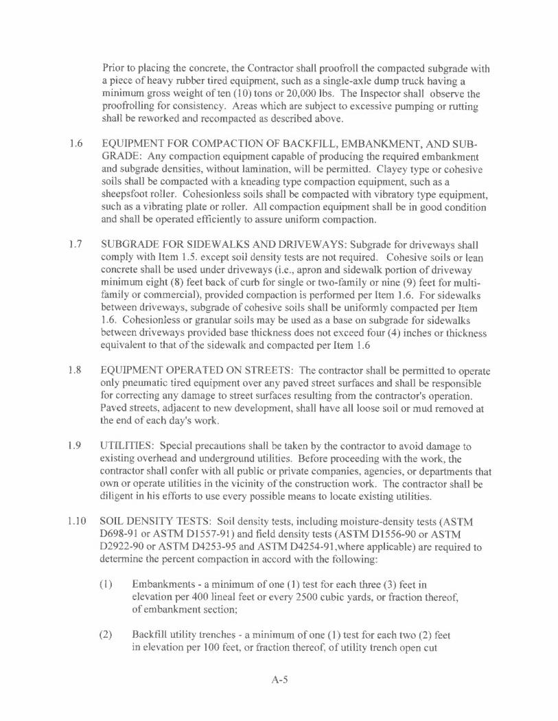
Prior to placing the concrete, the Contractor shall proofroll the compacted subgrade with a piece of heavy rubber tired equipment, such as a single-axle dump truck having a minimum gross weight of ten ( 10) tons or 20,000 lbs. The Inspector shall observe the proofrolling for consistency. Areas which are subject to excessive pumping or rutting shall be reworked and recompacted as described above.
1.6 EQUIPMENT FOR COMPACTION OF BACKFILL, EMBANKMENT, AND SUBGRAOE: Any compaction equipment capable of producing the required embankment and subgrade densities, without lamination, will be permitted. Clayey type or cohesive soils shall be compacted with a kneading type compaction equipment, such as a sheepsfoot roller. Cohesionless soils shall be compacted with vibratory type equipment, such as a vibrating plate or roller. All compaction equipment shall be in good condition and shall be operated efficiently to assure uniform compaction.
1.7 SUBGRAOE FOR SIDEWALKS AND DRIVEWAYS: Subgrade for driveways shall comply with Item 1.5. except soil density tests are not required. Cohesive soils or lean concrete shall be used under driveways (i.e., apron and sidewalk portion of driveway minimum eight (8) feet back of curb for single or two-family or nine (9) feet for multifamily or commercial), provided compaction is performed per Item 1.6. For sidewalks between driveways, subgrade of cohesive soils shall be uniformly compacted per Item 1.6. Cohesionless or granular soils may be used as a base on subgrade for sidewalks between driveways provided base thickness does not exceed four ( 4) inches or thickness equivalent to that of the sidewalk and compacted per Item 1.6
1.8 EQUIPMENT OPERA TED ON STREETS: The contractor shall be permitted to operate only pneumatic tired equipment over any paved street surfaces and shall be responsible for correcting any damage to street surfaces resulting from the contractor's operation. Paved streets, adjacent to new development, shall have all loose soil or mud removed at the end of each day's work.
1.9 UTILITIES: Special precautions shall be taken by the contractor to avoid damage to existing overhead and underground utilities. Before proceeding with the work, the contractor shall confer with all public or private companies, agencies, or departments that own or operate utilities in the vicinity of the construction work. The contractor shall be diligent in his efforts to use every possible means to locate existing utilities.
1.10 SOIL DENSITY TESTS: Soil density tests, including moisture-density tests (ASTM 0698-91 or ASTM Dl557-91) and field density tests (ASTM Dl556-90 or ASTM 02922-90 or ASTM D4253-95 and ASTM D4254-91,where applicable) are required to determine the percent compaction in accord with the following:
(I) Embankments - a minimum of one (1) test for each three (3) feet in elevation per 400 lineal feet or every 2500 cubic yards, or fraction thereof, of embankment section;
(2) Backfill utility trenches - a minimum of one (1) test for each two (2) feet in elevation per 100 feet, or fraction thereof, of utility trench open cut
A-5

beneath street subgrade and within the limits of the public right of way; and
Where depths of trenches are more than (5) feet and worker safety is at risk, the inspector shall observe the compaction process in layers with an appropriate type of compaction equipment and document observations until worker safety is assured when compaction testing, as required, is resumed.
(3) Subgrades - a minimum of one (I) test per 100 lineal feet for streets 500 lineal feet or less or one (I) test per 200 lineal feet for streets over 500 lineal feet at each of the following locations, where applicable:
(a) compacted fill placed for embankments;
(b) undisturbed soils in transitional areas from cut to fill immediately below the topsoil; and
(c) undisturbed soils at depths greater than 3 feet below the original ground in cut areas.
All soil density testing shall be at the expense of the developer. The results of these tests shall be mailed directly to the developer, design engineer, inspector, and the contractor. The results of all soil testing shall be compared to the densities, stated in Items 1.3, 1.4, and 1.5 of these regulations. Any deficiencies found in construction work must be remedied in the field or resolved between the developer, contractor, and inspector, subject to approval by a qualified/recognized geotechnical engineer.
Any deviations observed by the inspector in conflict with frequency of soil density testing shall include findings in accord with Section 7.13 A of these regulations.
ITEM 2.0 MATERIALS Concrete shall be composed of Portland Cement, air-entraining agent, aggregates, and water.
2.1 PORTLAND CEMENT: Cement of the type specified shall conform to requirements of the current ASTM specifications including Portland Cement Type I or Type III - High Early Strength (Designations C 150, C 175 or C 595). Cement, which for any reason has become partially set or which contains lumps of caked cement, shall be rejected. Either packaged or bulk cement may be used.
2.2 AIR-ENTRAINING AGENT: Air-entraining agents shall conform to the requirements of the current ASTM specifications for air-entraining admixtures for concrete (Designation c 260).
2.3 ADMIXTURES FOR CONCRETE: Chemical admixture of the type specified shall conform to requirements of the current ASTM specifications for Admixtures of Type A thru and Type E (Designation C 494). No pozzolans (Fly Ash) will be allowed as substitute for cement.
A-6
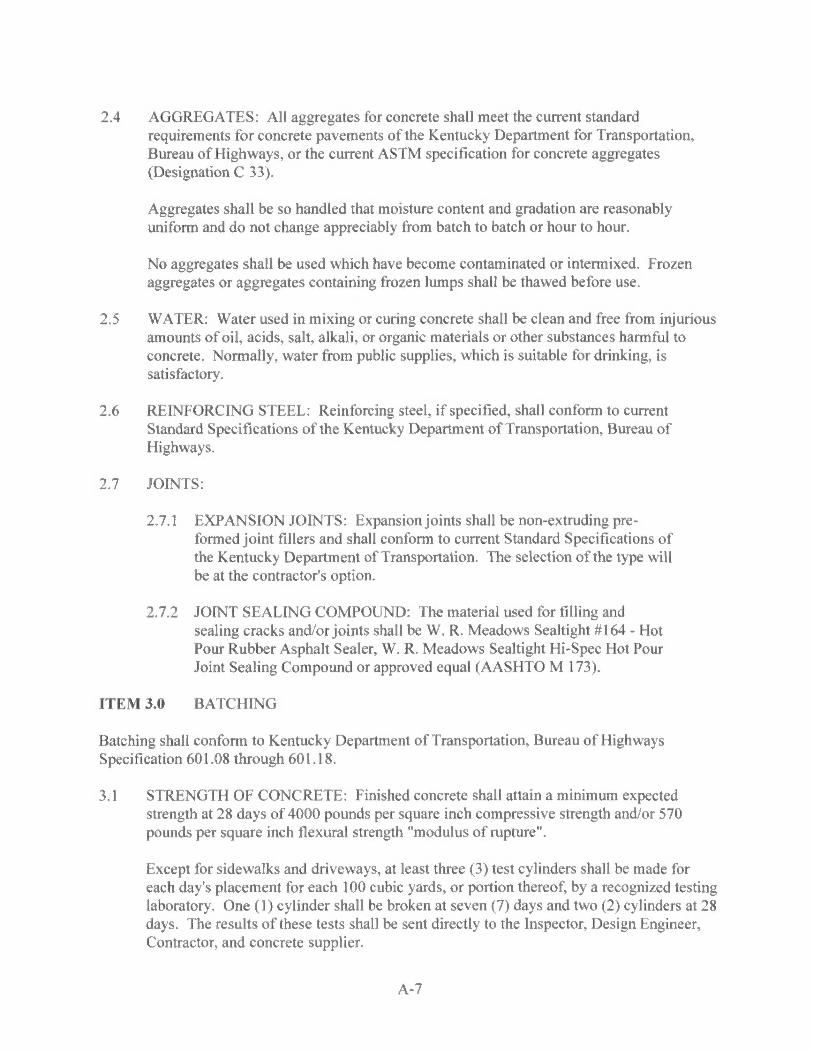
2.4 AGGREGATES: All aggregates for concrete shall meet the current standard requirements for concrete pavements of the Kentucky Department for Transportation, Bureau of Highways, or the current ASTM specification for concrete aggregates (Designation C 33).
Aggregates shall be so handled that moisture content and gradation are reasonably uniform and do not change appreciably from batch to batch or hour to hour.
No aggregates shall be used which have become contaminated or intermixed. Frozen aggregates or aggregates containing frozen lumps shall be thawed before use.
2.5 WATER: Water used in mixing or curing concrete shall be clean and free from injurious amounts of oil, acids, salt, alkali, or organic materials or other substances harmful to concrete. Normally, water from public supplies, which is suitable for drinking, is satisfactory.
2.6 REINFORCING STEEL: Reinforcing steel, if specified, shall conform to current Standard Specifications of the Kentucky Department of Transportation, Bureau of Highways.
2.7 JOINTS:
2.7.1 EXPANSION JOINTS: Expansionjoints shall be non-extruding preformed joint fillers and shall conform to current Standard Specifications of the Kentucky Department of Transportation. The selection of the type will be at the contractor's option.
2. 7.2 JOINT SEALING COMPOUND: The material used for filling and sealing cracks and/or joints shall be W. R. Meadows Sealtight # 164 - Hot Pour Rubber Asphalt Sealer, W.R. Meadows Sealtight Hi-Spec Hot Pour Joint Sealing Compound or approved equal (AASHTO M 173).
ITEM 3.0 BATCHING
Batching shall conform to Kentucky Department of Transportation, Bureau of Highways Specification 601.08 through 601.18.
3.1 STRENGTH OF CONCRETE: Finished concrete shall attain a minimum expected strength at 28 days of 4000 pounds per square inch compressive strength and/or 570 pounds per square inch flexural strength "modulus of rupture".
Except for sidewalks and driveways, at least three (3) test cylinders shall be made for each day's placement for each 100 cubic yards, or portion thereof, by a recognized testing laboratory. One (1) cylinder shall be broken at seven (7) days and two (2) cylinders at 28 days. The results of these tests shall be sent directly to the Inspector, Design Engineer, Contractor, and concrete supplier.
A-7

The fabricating, curing, breaking, and reporting the test cylinders, slump test, and air content test shall be made at the contractor's expense.
3.2 PROPORTIONING CONCRETE: The proper proportions of cement, water, and aggregates shall be determined in accordance with ACI Standard 613, "Recommended Practice for Selecting Proportions for Concrete", or the Portland Cement Association booklet, "Design and Control of Concrete Mixtures", latest editions.
The entrained air shall be obtained by using an air-entraining agent. All concrete shall be air-entrained in accordance with the following:
MAXIMUM SIZE OF AGGREGATE (INCHES)
1-1/2, 2, 2-112 3/4, 1 3/8, 1/2
AIR CONTENT PERCENT BY VOLUME
5 +I - 1% 6 +/ - 1%
7-1 /2 +/ -1%
3.3 CONSISTENCY: The slump of the concrete shall not exceed four (4) inches. Consistency shall be measured as described in the current ASTM Standard Method of Slump Test for Consistency of Portland Cement Concrete (Designation C 143 or Method of Test for Ball Penetration for Portland Cement Concrete, Designation C-360).
3.4 READY-MIXED CONCRETE: All ready-mixed concrete shall be furnished in accordance with current ASTM specifications for ready-mixed concrete (Designation C 94 or AASHTO M 157). Any concrete, which is not plastic and workable when it reaches the subgrade, shall be rejected.
3.4.1 TIME OF DELIVERY: Concrete shall be delivered and discharged from a truck mixer or agitator truck within a period of one and one-half (1-1 /2) hours at air temperatures up to eighty-five (85) degrees Fahrenheit, and one (1) hour at air temperatures higher than eighty-five (85) degrees Fahrenheit, after introduction of the water to the cement and aggregates or the cement to the aggregates. Delivery tickets shall have this time clearly shown thereon, and the inspector shall check to be certain that delivery is made within the period specified.
3.4.2 TYPE OF DELIVERY EQUIPMENT: Concrete shall be delivered in truck mixers or agitator truck (i.e., trucks providing mechanical agitation by revolving drums or revolving blades in a stationary drum) operated after time required for thorough mixing of the concrete at the speed designated by the manufacturer as agitating speed.
3.5 JOB-MIXED CONCRETE: Job-mixed concrete shall be mixed in a drum mixer, which shall conform to the concrete paving mixer standards of the Mixer Manufacturers Bureau of the Association General Contractors of America. The mixer shall be capable of combining the aggregates, cement, and water into a thoroughly mixed and uniform mass within the specified time and of discharging the material without segregation.
A-8
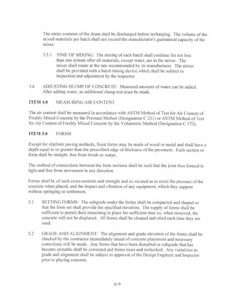
The entire contents of the drum shall be discharged before recharging. The volume of the mixed materials per batch shall not exceed the manufacturer's guaranteed capacity of the mixer.
3.5. l TIME OF MIXING: The mixing of each batch shall continue for not less than one minute after all materials, except water, are in the mixer. The mixer shall rotate at the rate recommended by its manufacturer. The mixer shall be provided with a batch timing device which shall be subject to inspection and adjustment by the inspector.
3.6 ADJUSTING SLUMP OF CONCRETE: Measured amounts of water can be added. After adding water, an additional slump test must be made.
ITEM 4.0 MEASURING AIR CONTENT
The air content shall be measured in accordance with ASTM Method of Test for Air Content of Freshly Mixed Concrete by the Pressure Method (Designation C 231) or ASTM Method of Test for Air Content of Freshly Mixed Concrete by the Volumetric Method (Designation C 173).
ITEM 5.0 FORMS
Except for slipform paving methods, fixed forms may be made of wood or metal and shall have a depth equal to or greater than the prescribed edge of thickness of the pavement. Each section or form shall be straight, free from bends or warps.
The method of connections between the form sections shall be such that the joint thus formed is tight and free from movement in any direction.
Forms shall be of such cross-sections and strength and so secured as to resist the pressure of the concrete when placed, and the impact and vibration of any equipment, which they support without springing or settlement.
5.1 SETIING FORMS: The subgrade under the forms shall be compacted and shaped so that the form set shall provide the specified elevation. The supply of forms shall be sufficient to permit their remaining in place for sufficient time so, when removed, the concrete will not be displaced. All forms shall be cleaned and oiled each time they are used.
5.2 GRADE AND ALIGNMENT: The alignment and grade elevation of the forms shall be checked by the contractor immediately ahead of concrete placement and necessary corrections will be made. Any forms that have been disturbed or subgrade that has become unstable shall be corrected and forms reset and rechecked. Any variations in grade and alignment shall be subject to approval of the Design Engineer and Inspector prior to placing concrete.
A-9
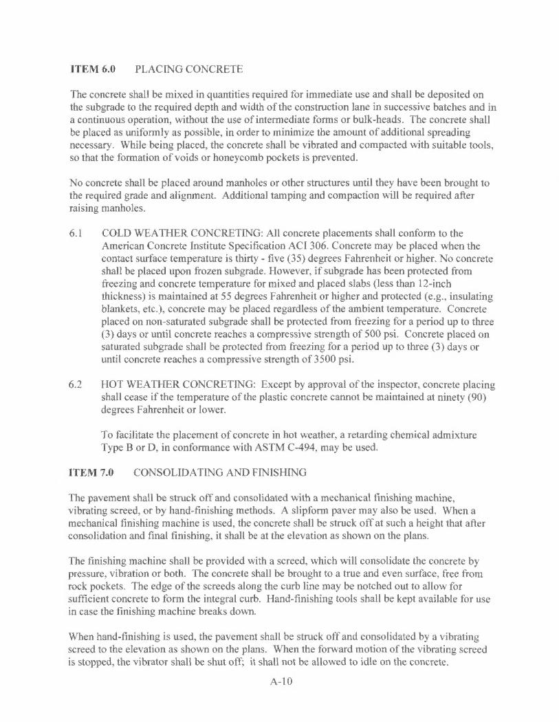
ITEM 6.0 PLACING CONCRETE
The concrete shall be mixed in quantities required for immediate use and shall be deposited on the subgrade to the required depth and width of the construction lane in successive batches and in a continuous operation, without the use of intermediate forms or bulk-heads. The concrete shall be placed as uniformly as possible, in order to minimize the amount of additional spreading necessary. While being placed, the concrete shall be vibrated and compacted with suitable tools, so that the formation of voids or honeycomb pockets is prevented.
No concrete shall be placed around manholes or other structures until they have been brought to the required grade and alignment. Additional tamping and compaction will be required after raising manholes.
6.1 COLD WEATHER CONCRETING: All concrete placements shall conform to the American Concrete Institute Specification ACI 306. Concrete may be placed when the contact surface temperature is thirty - five (35) degrees Fahrenheit or higher. No concrete shall be placed upon frozen subgrade. However, if subgrade has been protected from freezing and concrete temperature for mixed and placed slabs (less than 12-inch thickness) is maintained at 55 degrees Fahrenheit or higher and protected (e.g., insulating blankets, etc.), concrete may be placed regardless of the ambient temperature. Concrete placed on non-saturated subgrade shall be protected from freezing for a period up to three (3) days or until concrete reaches a compressive strength of 500 psi. Concrete placed on saturated subgrade shall be protected from freezing for a period up to three (3) days or until concrete reaches a compressive strength of 3500 psi.
6.2 HOT WEATHER CONCRETING: Except by approval of the inspector, concrete placing shall cease if the temperature of the plastic concrete cannot be maintained at ninety (90) degrees Fahrenheit or lower.
To facilitate the placement of concrete in hot weather, a retarding chemical admixture Type B or D, in conformance with ASTM C-494, may be used.
ITEM 7.0 CONSOLIDATING AND FINISHING
The pavement shall be struck off and consolidated with a mechanical finishing machine, vibrating screed, or by hand-finishing methods. A slipform paver may also be used. When a mechanical finishing machine is used, the concrete shall be struck off at such a height that after consolidation and final finishing, it shall be at the elevation as shown on the plans.
The finishing machine shall be provided with a screed, which will consolidate the concrete by pressure, vibration or both. The concrete shall be brought to a true and even surface, free from rock pockets. The edge of the screeds along the curb line may be notched out to allow for sufficient concrete to form the integral curb. Hand-finishing tools shall be kept available for use in case the finishing machine breaks down.
When hand-finishing is used, the pavement shall be struck off and consolidated by a vibrating screed to the elevation as shown on the plans. When the forward motion of the vibrating screed is stopped, the vibrator shall be shut off; it shall not be allowed to idle on the concrete.
A-10
7.1 SCRAPING AND STRAIGHTEOGING: The pavement may be required, by the inspector, where applicable, to be scraped with a straightedge, equipped with handles long enough to permit it to be operated from the edge of the pavement.
When irregularities are discovered, they shall be corrected by adding or removing concrete. All disturbed areas shall be floated with a wooden or metal float not less than three (3) feet long and not less than six (6) inches wide and again straight-edged.
7.2 EDGING: Before final finishing is completed, and before the concrete has taken its initial set, the edges of the slab and curb shall be carefully finished with an edger.
7.3 FINAL SURFACE FINISH: A burlap drag or medium broom shall be used as the final finishing method for concrete pavement. The drag shall be at least three (3) feet in width and long enough to cover the entire pavement width. It shall be laid on the surface of the pavement and dragged forward in the direction in which the pavement is being laid. If a broom finish is used, the brooming shall be drawn from the center to the edge of pavement using overlapping strokes to produce surface corrugations of uniform appearance about I/16th inch in depth. The curb shall have the same final finish as the pavement.
The final surface of the concrete pavement and curb shall have a uniform gritty texture, and true to the grades and cross-sections shown on the plans.
ITEM 8.0 INTEGRAL CURB
Curbs shall be required along the edges of all street pavement where shown on the plans and shall conform to cross sections. Curbs may be constructed simultaneously with the pavement with extrusion equipment, hand formed immediately after the finishing operation, or built as a separate construction operation.
The integral vertical and rolled curb shall be constructed with or immediately following the finished operation. Special care shall be taken so that the curb construction does not lag the pavement construction and form a "cold joint".
When integral vertical curbs are required along the edges of all street pavement, depressed curbs two (2) inches above gutter line shall be provided at all driveway entrances and at such other locations as designated on the approved plans.
In placing concrete curb, sufficient spading shall be done to secure adequate bond with paving slab and eliminate all voids within and back face of the curb.
Curbs shall be formed to the cross-section in accordance with Appendix "C".
ITEM 9.0 CURING
Concrete shall be cured by protecting it against loss of moisture, rapid temperature change, from rain, flowing water, and mechanical injury for a period of not less than five (5) days from the
A-11
beginning of the curing operation. Moist curing, waterproof paper, white pigmented liquid membrane compound, or a combination thereof, may be used for curing. Immediately after finishing operations have been completed, the entire surface of the newly placed concrete shall be covered by the curing medium which is applicable to local conditions and approved by the inspector.
The edge of concrete slabs exposed by the removal of forms shall be protected immediately to provide these surfaces and to prevent injury to concrete edges.
The covering material shall be kept free of any substances, which may be detrimental to the surface of the concrete. The initial curing medium shall be effective and shall be applied so as to prevent checking, cracking, and the appearance of dry spots in the surface of the concrete. The contractor shall have the equipment needed for adequate curing at hand and ready to install before actual concrete placement begins. In all cases in which the curing medium requires the use of water, the curing shall have prior right to all water supply. Failure to provide sufficient cover material of the type selected, failure to maintain saturation for the entire curing period in the moist-curing methods, lack of water to adequately care for both curing and other requirements, or other failures to comply with curing requirements shall be cause for immediate suspension of concreting operations.
9.1 MOIST CURING: Moist curing shall be accomplished by covering of burlap, cotton mats, or other approved fabric mat used singly or in combination.
Curing mats shall be thoroughly wet when applied and kept continuously wet and in intimate contact with the pavement surface for the duration of the moist curing period. Other fabric mats shall conform in design and shall provide a curing medium at least equal to cotton mats. Cotton mats, other fabric mats, and burlap mats and burlap strips shall be furnished in the widths or lengths, after shrinkage, required to cover the entire width and edges of the pavement lane. Mats or burlap shall be lapped at joints between adjacent sheets to prevent drying at this location. Moist curing, when used as initial curing, shall be continued for not less than twenty-four (24) hours. Type and weight of cotton mats for curing concrete shall conform to ASTM C-440 or AASHTO M-73. Burlap strips shall conform to AASHTO M-182.
9.2 WATERPROOF PAPER AND POLYTHENE SHEETING CURING: The surface of the concrete shall be wetted with a fine spray of water and then covered with the waterproof paper or sheeting. The paper or sheeting shall be in pieces large enough to cover the entire width and edges of the slab and shall be lapped not less than twelve ( 12) inches. Paper or sheeting shall be adequately weighted to prevent displacement or billowing due to wind. Paper or sheeting folded down over the side of the pavement widths shall be secured by a continuous bank of earth. Tears or holes appearing in the paper or sheeting during the curing period shall be immediately repaired.
9.3 LIQUID MEMBRANE CURING COMPOUND: Pigmented liquid membrane curing compound shall meet the specifications under ASTM C 309 classified as Type 1-D translucent with fugitive dye, Type 2 - white pigmented or approved equal. The curing compound must be applied to cover the surface completely and uniformly at a rate which will achieve the performance requirement specified in AASHTO specifications M 148 or
A-12

ASTM Designation C 309. This method of curing shall be applied immediately behind the final finishing operation or after the initial curing when a combination of methods are used. Failure to provide complete and uniform coverage at the required rate will be cause for discontinuance of this method of curing and the substitution of one of the other approved methods. The compound shall be kept agitated to prevent the pigment from settling. Special care shall be taken to apply the curing compound to the pavement edges immediately after the forms have been removed.
9.4 ADJACENT WORK: Grading operations for preparation of subgrade for asphalt streets adjacent to "plastic or green" concrete curb shall be suspended for at least twenty - four (24) hours after initial curing operations have been completed. Extreme caution shall be used with machinery including vibratory equipment in order to prevent chipping or fracture of such new concrete curb pavements. Any damaged sections of curb shall be removed and replaced prior to start of the next phase of work.
ITEM 10.0 PAVEMENT JOINTS (all joints shall be constructed as per details in Appendix "C")
Concrete pavement shall include expansion, contraction, and longitudinal joints. Transverse joints may be expansion and contraction type joints which shall be continuous across the pavement lane including the curb. Longitudinal joints are parallel to the pavement lanes. Construction joints are necessary when the placement of concrete is delayed. The location of transverse construction joints may be either planned (coincidental with a contraction joint) or emergency (not coincidental with a contraction joint). In general, the location of longitudinal joints shall be centered between pavement lanes except for street widths 30 feet and wider.
The placement and construction of all pavement joints shall comply with joint details in Appendix "C" and shall be shown or referenced on the Improvements Drawings in accord with the following criteria:
I 0.1 EXP ANSI ON JOINTS
Expansion joints shall be Type I. Filler material shall conform to Item 2.7.1 of these regulations and extend the entire width of the pavement. The filler shall be held accurately in place during the placing and finishing of the concrete by a bulkhead, a metal channel cap or other approved method. Expansion joints shall be installed at the following locations: ( 1) at all street intersections at the point of curvature of the turning radii entering the intersection; and (2) at cul-de-sacs or turnarounds at the point of curvature of the first turning radii approaching the tum-around. In no case shall the expansion joint spacing exceed 150 feet.
No concrete shall be left above the expansion material or across the joint at any point. Any concrete spanning the ends of the joint next to the forms shall be carefully cut away after the forms are removed.
Before the pavement is opened to traffic, the groove above the filler shall be cleaned and sealed with joint sealing material specified in Item 2.7.2 of these regulations.
A-13
10.2 CONTRACTION JOINTS
Transverse joints shall be Type 2. Sawed joints shall be equal to a depth of one-fourth (1/4) of the pavement thickness as the minimum established standard continuous across the slab including additional depth at the integral curb faces. Such joints may also be grooved with a metal jointing tool to a depth of one and one half ( 1-112) inches including additional depth and special treatment at integral curb faces to control cracking. Other joint depths used with alternate pavement designs including stabilized pavement subbases shall be shown on the plans and reviewed per industry standards.
In no case shall the contraction joint be spaced at intervals greater than a distance of fifteen (15) feet between joints for integral curb concrete pavement. For concrete curb used with asphalt pavement, contraction joints shall be space at intervals not greater than ten (10) feet.
Where sawed joints are specified, they shall be sawed within a time frame of between four ( 4) hours and eight (8) hours following placement of each pavement section. However, depending upon temperature, weather conditions, and other factors affecting setting times, variations to these time frames may be required to ensure that joints are sawed early enough to control cracking, but late enough to prevent any damage by blade action to the slab surface and to the concrete immediately adjacent to the joint.
10.3 CONSTRUCTION JOINTS
Transverse construction joints shall be used wherever the placing of concrete is suspended for more than thirty (30) minutes. A transverse construction joint shall be Type 3, with smooth bars (one end lubricated) if the joint occurs at the location of a contraction joint. A transverse construction joint shall be Type 4 with deformed tie bars (both ends bonded) if the joint occurs at any other location. Both Type 3 and Type 4 joints shall be butt type construction formed. In the case of integral curb concrete pavement where construction joints are sawed they shall be saw cut full depth where no vertical face of concrete is undermined creating a void under the pavement. In the case of concrete curb and gutter used with asphalt pavement, special care should be taken to ensure that all surfaces including the joint are uniform and result in the same integrity as an integral curb concrete placement.
10.4 LONGITUDINAL JOINTS
Longitudinal joints between lanes shall be Type 6 of the tied construction type. An alternative longitudinal joint Type 7 may be used with slip-form paving operations. As an option to drilling diagonal bars in Type 7, bent bars may also be injected in fresh concrete before it's initial set. Following subgrade preparation and testing, bent bars shall not be straightened until the concrete has cured sufficiently to enable bending without fracture of concrete slab as determined by the inspector. The location of longitudinal joints shall be centered between pavement lanes and coincide with lane markings wherever possible, except for street widths of thirty (30) feet and wider where joints shall be located at equal intermediate locations. In these cases, longitudinal joints may be sawed and shall be Type S.
A-14

I 0.5 INTEGRAL CURB JOINTS
In the construction of transverse joints, special care must be taken to ensure that all transverse joints extend continuously through the pavement and curb per Items I 0.2 and I 0.3 of these regulations.
ITEM 11.0 TIE BARS
All tie bar reinforcement for concrete pavement shall conform to Item 2.6 of these regulations. All tie bars shall be deformed bars for Types 4, 5, 6, and 7, and plain or smooth bars for Type I and 3, as detailed in Appendix "C".
ITEM 12.0 JOINT SEALER
Pavement joint sealer shall be as specified in Item 2.7.2 of these regulations. Application of joint sealer shall be as follows:
Material must be melted in a double boiler, oil jacketed melter equipped with a mechanical agitator, pump, gas pressure gauges, and separate temperature thermometers for both oil bath and melting vat, with accessible control valves and gauges.
On start up of melter, raise the oil bath temperature, not to exceed 450 degrees (F). Add small quantities of crack filler material to the melter and, while continuously agitating, add additional material as needed. Control material temperature at 380 degrees (F). Do not exceed 400 degrees (F) at start up.
The sealing and filling of joints and/or cracks may be done at air temperature of 40 degrees (F) or higher. For best results, cracks should be filled to a depth of 114 inch below the surface. Where necessary to limit the depth of the sealant, use cotton or kraft rope inserted to the correct depth of the cleaned joint or crack.
Small quantities of unused material remaining in the melter may be remelted and used the following day.
ITEM 13.0 STRUCTURES ENCOUNTERED IN THE PAVED AREA
13. l MANHOLES AND CATCH BASINS: All manholes and catch basins encountered in the areas to be paved shall be raised or lowered to the surface of the new pavement. Catch basins may be separated from the pavement and curb by boxing out around basin. See Appendix "C".
ITEM 14.0 PROTECTION AND OPENING TO TRAFFIC
Traffic shall be excluded from the pavement by erecting and maintaining barricades and signs until the concrete is at least seven (7) days old or has attained a compressive strength of 3,500 pounds per square inch and/or a flexural strength of 550 per square inch using Type I Normal
A-15

Cement certified by a qualified/recognized geotechnical engineer. Other protection and opening to traffic decisions on other pavement designs using Type III High Early Strength Cement shall be reviewed per industry standards. This traffic restriction shall apply to the contractor's vehicles, as well as general traffic. As soon as curing and sealing are completed, the contractor shall clean up the pavement free from all debris.
ITEM 15.0 CURB, GUTTER, SIDEWALK, AND DRIVEWAYS
Construction of curb, gutter, sidewalk, and driveways shall require the same care as the street pavement. The preceding requirements shall apply, where pertinent, to the construction of curb, gutter, sidewalks, and driveways within the right-of-way. In addition, sidewalks or driveways shall be constructed so that the transverse joint spacing shall be equal to the width of the sidewalk or driveway, but in no case shall the transverse joint spacing for driveways exceed twelve (12) feet and not greater than five (5) feet for sidewalk spacing. Sidewalks and driveways, within the right-of-way, shall be constructed with a pavement thickness of at least four (4) inches and increased to five (5) inches when included as a part of a driveway. Driveways shall be a minimum of five (5) inches in thickness within the right-of-way. (see Appendix "C" for typical section details). Commercial and industrial entrances will require sidewalk thickness conforming to driveway pavement thickness.
ITEM 16.0 PAVEMENT THICKNESS
Pavement thickness for each type street classification shall be as provided in Table A-1. Streets that are subjected to exceptionally heavy truck traffic shall require a more complete detailed analysis by the subdivider's engineer and approved by the planning commission's duly authorized representative.
All arterial streets shall be designed in accordance with the requirements of the Kentucky Department of Transportation.
16.1 TOLERANCE IN PAVEMENT THICKNESS: Deficiency in pavement thickness determined by drilling or coring new concrete pavement shall not exceed 0.20_inches. When thickness of pavement is deficient by more than 0.20 inches, such areas shall be removed and/or replaced unless otherwise determined by the inspector and a qualified registered professional engineer.
16.2 SURF ACE TOLERANCE: The finished surface shall be tested for smoothness by use of a 10-foot long straightedge placed parallel to the centerline of the pavement in each wheel lane. Ordinates measured from the face of the straightedge to the surface of the pavement shall at no place exceed one-quarter inch. Areas that do not meet the required surface accuracy shall be clearly marked out and the Contractor shall, at his own expense, as required by the planning commission's duly authorized representative:
1. Grind down any areas higher than 1/4 inch but not more than 112 inch above the correct surface.
2. Correct any areas lower than 1/4 inch but not lower than 1/2 inch below the correct surface by grinding down the adjacent areas.
A-16
3. When the deviation exceeds 112 inch from the correct surface, the pavement slab shall be broken out and replaced for a length, width and depth, which will allow the formation of a new slab of the required quality in no way inferior to the adjacent undisturbed slab.
A-17
*
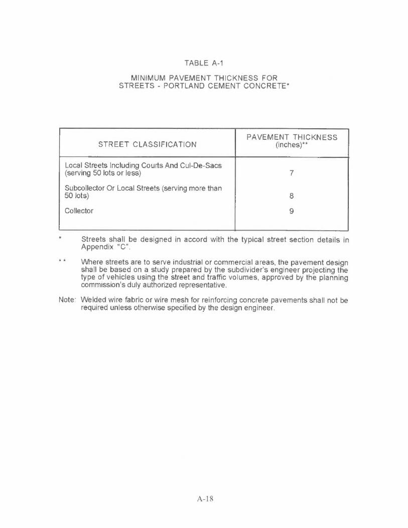
TABLE A-1
MINIMUM PAVEMENT THICKNESS FOR STREETS - PORTLAND CEMENT CONCRETE*
PAVEMENT THICKNESS STREET CLASSIFICATION (inches)**
Local Streets Including Courts And Cul-De-Sacs (serving 50 lots or less) 7
Subcollector Or Local Streets (serving more than 50 lots) 8
Collector 9
Streets shall be designed in accord with the typical street section details in Appendix "C".
• * V\/here streets are to serve industrial or commercial areas, the pavement design shall be based on a study prepared by the subdivider's engineer projecting the type of vehicles using the street and traffic volumes, approved by the planning commission's duly authorized representative .
Note: Welded wire fabric or wire mesh for reinforcing concrete pavements shall not be required unless otherwise specified by the design engineer.
A-18