Embed Size (px)
Citation preview
"Holderbank" - Cement Course 2000
© Holderbank Management & Consulting, 2000 6/23/2001 - 4:33:29 PM Page 1Query:
Process Technology / B05 - PT II
B05 - PT II

"Holderbank" - Cement Course 2000
© Holderbank Management & Consulting, 2000 6/23/2001 - 4:33:29 PM Page 2Query:
Process Technology / B05 - PT II / C01 - Kiln Systems
C01 - Kiln Systems
"Holderbank" - Cement Course 2000
© Holderbank Management & Consulting, 2000 6/23/2001 - 4:33:29 PM Page 3Query:
Process Technology / B05 - PT II / C01 - Kiln Systems / Kiln Systems - Overview
Kiln Systems - OverviewUrs GasserPT 99/14501/E
1. PROCESS REQUIREMENTS FOR KILN SYSTEMS
2. PROCESS TYPES
2.1 General
3. WET PROCESS
3.1 General
3.2 Long Wet Process Kilns
3.3 Wet Process Kilns with Slurry Preheaters
4. SEMI WET PROCESS
4.1 General
4.2 Semi Wet Process Long Kilns
4.3 Semi Wet Grate Preheater Kilns
4.4 Semi-Wet Suspension Pre-heater Kiln
5. SEMI DRY PROCESS
5.1 Semi-Dry Process Long Kilns
5.2 Semi-Dry Process Grate Pre-heater Kilns
6. DRY PROCESS
6.1 Long Dry Kilns
6.2 Raw Meal Suspension Preheater Kilns
6.2.1 General
6.2.2 One and two Stage Cyclone Pre-heater Kilns
6.2.3 Four Stage Cyclone Pre-heater Kilns
6.2.4 Precalciner Kilns

"Holderbank" - Cement Course 2000
© Holderbank Management & Consulting, 2000 6/23/2001 - 4:33:29 PM Page 4Query:
SUMMARY
Today’s kiln systems for burning cement clinker of major importance use a rotary kiln. Exceptions arevertical shaft kilns still used in certain geographical areas. With very rare exceptions, new plants usethe dry process. However, there are still important markets where older wet process plants arepredominant (USA, Russia).
A first classification of the process can be made based on the water content of the kiln feed:
< 1% water dry-process
10 ... 12% water semi-dry-process
17 ... 21% water semi-wet-process
25 ... 40% water wet-process
♦ Dry-Process
• Precalciner kiln with 4 to 6 cyclone stages (contemporary technology):∗ Separate tertiary air duct∗ 50 - 60% fuel to the precalciner∗ Large capacities possible > 10000 t/d∗ Up to 4000 t/d in 1 string∗ Heat consumption < 3000 kJ/kg possible (6 stages)∗ Sensitive to circulation phenomena (-> kiln gas bypass!)
• 4-stage cyclone pre-heater kiln (standard technology 1970 to 1980):∗ Cyclone stages (co-current flow) for raw meal preheating∗ Large application world wide∗ Capacities of up to 4500 t/d technically possible∗ Heat consumption: 3150 to 3350 kJ/kg cli∗ Sensitive to circulation phenomena (-> kiln gas bypass!)
• 2-stage cyclone pre-heater kiln:∗ Less sensitive to circulation phenomena than 4-stage pre-heater∗ Higher heat consumption than pre-heater with more stages
• Shaft pre-heater kiln:∗ Counter current heat exchange between hot gas and raw meal∗ Practical efficiency inferior to cyclone pre-heater
• Long-dry-kiln:∗ Rather simple equipment∗ High dust emission from kiln tube∗ Without heat exchange internals: high heat consumption of up to 5100 kJ/kg cli∗ With chains and/or crosses: 4200 kJ/kg cli achievable
♦ Semi-dry and semi wet process
• Grate pre-heater kiln (LEPOL, ACL):∗ Raw meal must be suitable to be nodulised with water (semi-dry)

"Holderbank" - Cement Course 2000
© Holderbank Management & Consulting, 2000 6/23/2001 - 4:33:30 PM Page 5Query:
∗ 3450 kJ/kg cli (no waste heat available for primary raw material drying)
• Long rotary kiln and suspension preheater:∗ Filter cakes fed or slurry injection into vertical dryer; rather rare cases
♦ Wet-process
• Long wet kiln:∗ Fed with raw meal slurry of approx. 32 - 42% water content∗ Internal heat transfer improved by chains∗ High heat consumption of 5300 to 6300 kJ/kg cli due to evaporation of water∗ Heat consumption reduced by slurry thinners for a slurry with 25 - 30% H2O∗ Slurry preheaters can reduce kiln size and improve heat exchange
Process Technology / B05 - PT II / C01 - Kiln Systems / Kiln Systems - Overview / 1. PROCESS REQUIREMENTS FOR KILNSYSTEMS
1. PROCESS REQUIREMENTS FOR KILN SYSTEMS
The kiln system has to be designed to cope with the requirements of the chemical process duringwhich the kiln feed material is converted into cement clinker.
This process as a whole is endothermic and takes place at maximum material temperatures of 1450°C.Receiving its thermal energy from hot gases of up to 2000°C generated by combusting fuels, it is alsoreferred to as pyroprocess.
Type of reaction and temperature development are compiled in “sequence of reactions occurring in arotary kiln” (table 1) and graphically as the “quasi-qualitative variation of minerals with temperature”(figure 1).
The chemical process taking place in the kiln system where raw meal (input) is converted to cementclinker (output) can be subdivided into the following five steps:
1. Drying
2. Preheating
3. Calcining
4. Sintering
5. Cooling
Process and equipment has been developed and improved with the aim at performing these stepsforever improved economy, which means
• High availability
• Low heat consumption
• Low power consumption
• Higher unit capacity
• Stable kiln operation
• Good, uniform clinker quality
Table 1 Sequence of Reactions occurring in a Rotary Kiln

"Holderbank" - Cement Course 2000
© Holderbank Management & Consulting, 2000 6/23/2001 - 4:33:30 PM Page 6Query:
Temperaturerange (°C)
Type of reaction
Heating Up
20 - 100 Evaporation of free H2O
100 - 300 Loss of physically absorbed water
400 - 900 Removal of structural H2O (H2O and OH groups) from clay minerals
> 500 Structural changes in silicate minerals
600 - 900 Dissociation of carbonates CO2 driven out)
> 800 Formation of belite, intermediate products, aluminate and ferrite
> 1250 Formation of liquid phase (aluminate and ferrite melt)
approx. 1450 Completion of reaction and re-crystallisation of alite and belite
Cooling
1300 - 1240 Crystallisation of liquid phase into mainly aluminate and ferrite
Process Technology / B05 - PT II / C01 - Kiln Systems / Kiln Systems - Overview / 2. PROCESS TYPES
2. PROCESS TYPES
Process Technology / B05 - PT II / C01 - Kiln Systems / Kiln Systems - Overview / 2. PROCESS TYPES / 2.1 General
2.1 General
The criterion normally used to distinguish the process types is the moisture of the kiln feed material.Four basically different process types for clinker burning can be defined:
Process Type Feed Material Cons. Feed Moisture Feed System
Dry process Raw meal Dry < 1% H2O Mechanic, pneumatic
Semi dry process Nodules Moist ≈ 10 ... 12% H2O Mechanic, pneumatic
"Holderbank" - Cement Course 2000
© Holderbank Management & Consulting, 2000 6/23/2001 - 4:33:31 PM Page 7Query:
≈ 10 ... 12% H2O
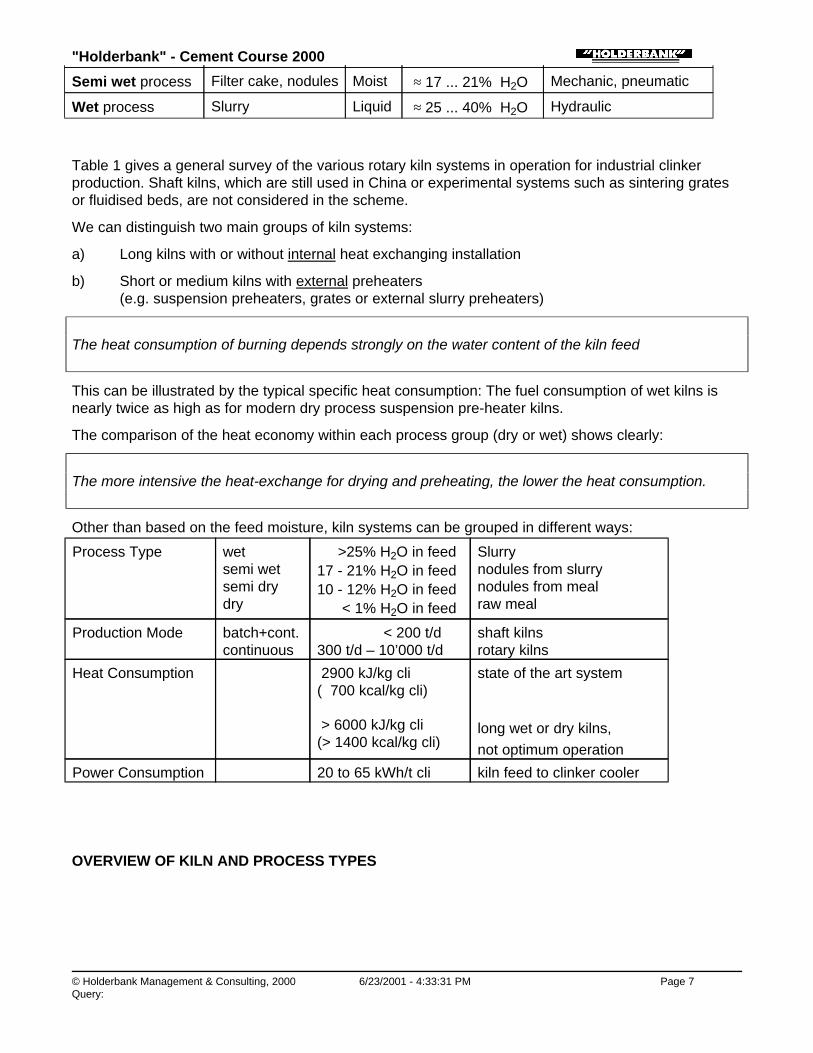
Semi wet process Filter cake, nodules Moist ≈ 17 ... 21% H2O Mechanic, pneumatic
Wet process Slurry Liquid ≈ 25 ... 40% H2O Hydraulic
Table 1 gives a general survey of the various rotary kiln systems in operation for industrial clinkerproduction. Shaft kilns, which are still used in China or experimental systems such as sintering gratesor fluidised beds, are not considered in the scheme.
We can distinguish two main groups of kiln systems:
a) Long kilns with or without internal heat exchanging installation
b) Short or medium kilns with external preheaters (e.g. suspension preheaters, grates or external slurry preheaters)
The heat consumption of burning depends strongly on the water content of the kiln feed
This can be illustrated by the typical specific heat consumption: The fuel consumption of wet kilns isnearly twice as high as for modern dry process suspension pre-heater kilns.
The comparison of the heat economy within each process group (dry or wet) shows clearly:
The more intensive the heat-exchange for drying and preheating, the lower the heat consumption.
Other than based on the feed moisture, kiln systems can be grouped in different ways:
Process Type wetsemi wetsemi drydry
>25% H2O in feed17 - 21% H2O in feed10 - 12% H2O in feed < 1% H2O in feed
Slurrynodules from slurrynodules from mealraw meal
Production Mode batch+cont.continuous
< 200 t/d300 t/d – 10’000 t/d
shaft kilnsrotary kilns
Heat Consumption 2900 kJ/kg cli( 700 kcal/kg cli)
> 6000 kJ/kg cli(> 1400 kcal/kg cli)
state of the art system
long wet or dry kilns, not optimum operation
Power Consumption 20 to 65 kWh/t cli kiln feed to clinker cooler
OVERVIEW OF KILN AND PROCESS TYPES

"Holderbank" - Cement Course 2000
© Holderbank Management & Consulting, 2000 6/23/2001 - 4:33:32 PM Page 8Query:
When the concept for a new plant is developed, not only the present situation but also the possiblefuture developments of all relevant factors must be taken into account.
The following main parameters must be considered when selecting the kiln system:
• Raw material:∗ moisture content∗ grindability∗ homogeneity of deposit∗ number of components for raw mix∗ chemical composition (sulphur, chlorides, alkalis, organic compounds etc)∗ filtration properties of slurry (for semi-wet process only)
• Plant installation and operating costs
• Requirements for clinker quality (e.g. low alkali clinker)
• Aspects of environmental protection (emission of dust, SOx, NOx, etc)
• Technical standard of the country
Long wet (and dry) rotary kilns are the oldest and most simple type of installation to produce cementclinker. The pyroprocess takes place in a long rotating tube, which has usually internal equipment toimprove heat transfer, and, in wet kilns, to reduce dust loss. Unit capacities of up to 2000 t/d aretypically achieved, higher outputs are possible, however, they require kilns of gigantic dimensions.
Today, economy requires plants for 3000 to 10’000 t/d. Therefore new plants are almost always basedon the dry process with preheater, pre-calciner and reciprocating grate cooler. The semi wet processfor a new plant could be preferred in special cases, e.g. where raw material with a high naturalmoisture must be used (e.g. quarry below water level).
The three following graphs illustrate the development of the significance of the various processeswithin the Holderbank group, which can be considered representative of the global situation.

"Holderbank" - Cement Course 2000
© Holderbank Management & Consulting, 2000 6/23/2001 - 4:33:32 PM Page 9Query:
Process Technology / B05 - PT II / C01 - Kiln Systems / Kiln Systems - Overview / 3. WET PROCESS
3. WET PROCESS
Process Technology / B05 - PT II / C01 - Kiln Systems / Kiln Systems - Overview / 3. WET PROCESS / 3.1 General
3.1 General
The wet process was the most important process for clinker burning in the past and almost all plantswere wet. Heterogeneous quarries and corrective addition were no problem; stirring of the liquid slurryin the slurry tanks provides very good batch-wise blending. Grinding was done in slurry mills, whichconsume 30%, less energy than dry ball mills, but at higher lining wear rates.

"Holderbank" - Cement Course 2000
© Holderbank Management & Consulting, 2000 6/23/2001 - 4:33:32 PM Page 10Query:
The disadvantage of the wet process is the high heat consumption. Compared to e.g. a suspensionpreheater kiln, the difference is more than 2000 kJ/kg clinker or 60 to 70%!
Today, with efficient dry homogenising technology available, the wet process is no longer applied fornew plants. Investments as well as operating costs of a wet system are higher than for dry systems ofthe same output. Technical development allows using more efficient kiln systems even where wetplants would have been built in earlier times.
Another reason for preferring the wet process in the past was the production of low alkali cement (alkalicontent < 0,6%) and the fact that difficult circulation problems are easier to control in wet kilns. Todaysecondary firing or efficient bypass installations with precalciner are possibilities to keep theseproblems under control also in modern kiln systems.
Because of the lower specific gas volume and the shorter rotary part, rotary kiln dimensions as well asgas handling, dedusting and fuel preparation can be designed accordingly smaller. Although new wetkilns are no longer considered for new plants, they still play an important role in the US as well as inmany countries of Eastern Europe and Central Asia.
Process Technology / B05 - PT II / C01 - Kiln Systems / Kiln Systems - Overview / 3. WET PROCESS / 3.2 Long Wet Process Kilns
3.2 Long Wet Process Kilns
Long wet kilns have been the most commonly used burning reactors for a very long time, but becauseof the high water content of the feed, their heat consumption is up to twice as high as for modern drysystems.
The milled and homogenised raw material is a slurry with a water content of typically 32 to 42% and ispumped to the kiln inlet.
In the first zone heat transfer for the evaporation of water is always increased by means of chainsystems (extended surface, higher relative velocities, increase of turbulence). The chain systemsshould also reduce the dust losses and clean the kiln shell. These internal heat exchanger installationsrequire very special know-how, based to a large degree on experience (see separate paper ‘chainsystems’).
In order to decrease fuel consumption the water content should be kept as low as possible. The limit isnormally the pumpability of the slurry. It is basically possible to further reduce the slurry moisture byusing slurry thinners. This technology has been successfully applied and will provide an economicaladvantage if adequate quantities are available at low cost, e.g. as industrial by-product.
Example: Beauport (Canada): 28% feed moisture
"Holderbank" - Cement Course 2000
© Holderbank Management & Consulting, 2000 6/23/2001 - 4:33:34 PM Page 11Query:
Wet kilns are relatively insensitive to circulation problems because the critical temperature ranges arein the rotary part of the kiln (see also ‘circulation phenomena’).
Low alkali clinker can be produced from high alkali raw material simply by selectively wasting of dust:The highest enriched kiln dust (e.g. from the last precipitator compartment) is removed from theprocess (i.e. dumped onto a dust pile) as necessary. The rest of the dust can be reintroduced to thekiln by dust scoops or insufflation into the burning zone.
Today, discarding dust creates increasing problems because of restrictive permitting of dust piles.
Note: Kiln dust cannot just be blended to the slurry because it would react and thicken the slurry.
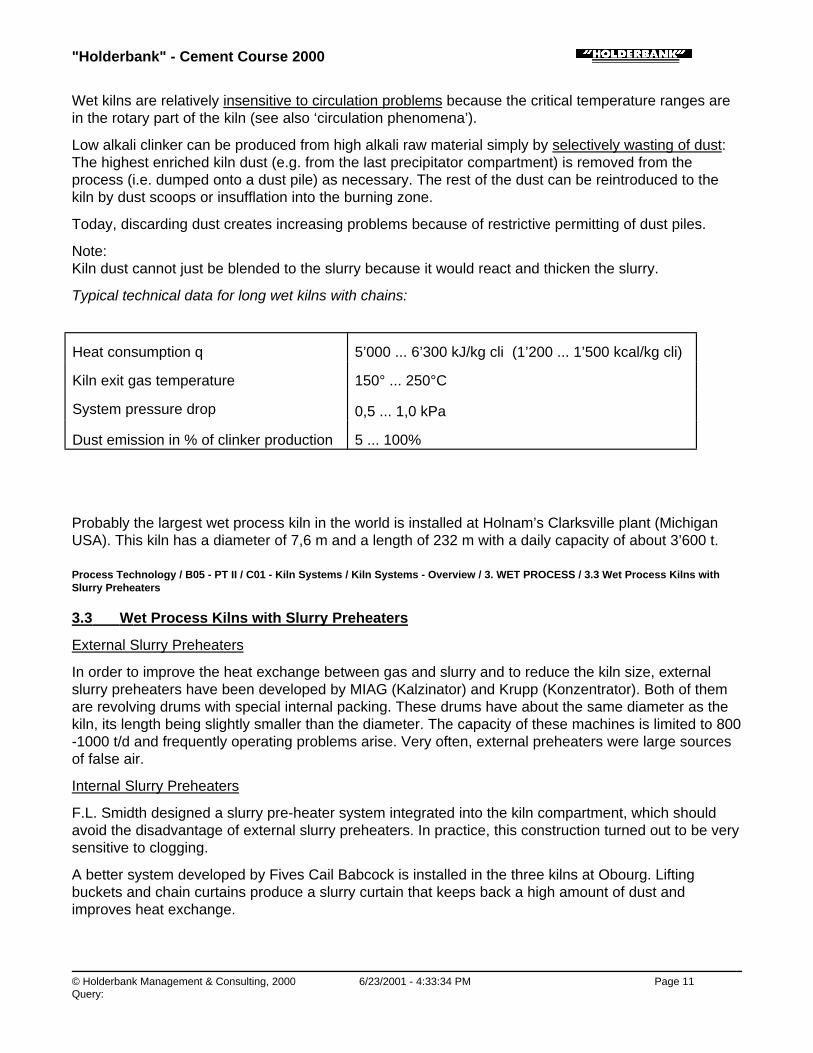
Typical technical data for long wet kilns with chains:
Heat consumption q 5’000 ... 6’300 kJ/kg cli (1’200 ... 1’500 kcal/kg cli)
Kiln exit gas temperature 150° ... 250°C
System pressure drop 0,5 ... 1,0 kPa
Dust emission in % of clinker production 5 ... 100%
Probably the largest wet process kiln in the world is installed at Holnam’s Clarksville plant (MichiganUSA). This kiln has a diameter of 7,6 m and a length of 232 m with a daily capacity of about 3’600 t.
Process Technology / B05 - PT II / C01 - Kiln Systems / Kiln Systems - Overview / 3. WET PROCESS / 3.3 Wet Process Kilns withSlurry Preheaters
3.3 Wet Process Kilns with Slurry Preheaters
External Slurry Preheaters
In order to improve the heat exchange between gas and slurry and to reduce the kiln size, externalslurry preheaters have been developed by MIAG (Kalzinator) and Krupp (Konzentrator). Both of themare revolving drums with special internal packing. These drums have about the same diameter as thekiln, its length being slightly smaller than the diameter. The capacity of these machines is limited to 800-1000 t/d and frequently operating problems arise. Very often, external preheaters were large sourcesof false air.
Internal Slurry Preheaters
F.L. Smidth designed a slurry pre-heater system integrated into the kiln compartment, which shouldavoid the disadvantage of external slurry preheaters. In practice, this construction turned out to be verysensitive to clogging.
A better system developed by Fives Cail Babcock is installed in the three kilns at Obourg. Liftingbuckets and chain curtains produce a slurry curtain that keeps back a high amount of dust andimproves heat exchange.

"Holderbank" - Cement Course 2000
© Holderbank Management & Consulting, 2000 6/23/2001 - 4:33:34 PM Page 12Query:
Process Technology / B05 - PT II / C01 - Kiln Systems / Kiln Systems - Overview / 4. SEMI WET PROCESS
4. SEMI WET PROCESS
Process Technology / B05 - PT II / C01 - Kiln Systems / Kiln Systems - Overview / 4. SEMI WET PROCESS / 4.1 General
4.1 General
A process is considered semi-wet if the kiln feed is produced from wet slurry. A mechanical waterextraction process reduces the water content of the kiln feed to 17 to 21%. A number of filter pressesoperating batch-wise are commonly used, but also continuous filter band presses or similar equipmentwould be possible.
Process Technology / B05 - PT II / C01 - Kiln Systems / Kiln Systems - Overview / 4. SEMI WET PROCESS / 4.2 Semi Wet ProcessLong Kilns
4.2 Semi Wet Process Long Kilns

"Holderbank" - Cement Course 2000
© Holderbank Management & Consulting, 2000 6/23/2001 - 4:33:36 PM Page 13Query:
Principally, long kilns with heat exchanger crosses can be fed with slurry, filter cakes or dry meal.Feeding filter cakes is a straightforward and simple solution and is used by Italcementi in some cases.
Process Technology / B05 - PT II / C01 - Kiln Systems / Kiln Systems - Overview / 4. SEMI WET PROCESS / 4.3 Semi Wet GratePreheater Kilns
4.3 Semi Wet Grate Preheater Kilns
Most of the semi-wet systems use a grate preheater kiln fed with filter cakes.
A grate preheater system includes a short rotary kiln (similar to a four stage preheater kiln) where onlycalcining and sintering take place. For drying, preheating and partial calcining, a travelling grate isinstalled in front of the kiln, where heat of the kiln exhaust gases is used.
For the semi-wet grate kiln, the slurry must be prepared in a special way so it can be fed to a travellinggrate:
The pumpable slurry as starting material is fed to filter presses where the moisture content is reducedto approx. 20% applying a filtration pressure of 15 to 20 bar. In a special type of extruder (Siebkneter),the filter cakes are converted into cylindrical nodules (diameter 15 ... 20 mm, length 30 ... 50 mm) andthen fed to the preheater-grate. The economy of this way of preparation depends strongly on thefiltration properties of the slurry.
Operating and performance data are similar to the semi-dry grate preheater systems described under5.2.
Characteristic data of a semi-wet grate pre-heater system:
Feed Nodules made fromMoisture Content of the Feed
Slurry Filter Cake10 ... 12%
Heat consumption q 3770 kJ/kg cli (≈ 900 kcal/kg cli)
Exit gas temperature after grate 100° ... 120°C
System pressure drop 2,6 kPa
Example of a semi-wet LEPOL kiln:
AB’s kiln 10 at the Lägerdorf plant (Germany)
Maximum kiln capacity: 3’600 t/d
Kiln dimensions: φ 6.0/5.6 m x 90 m
Grate dimensions: 5.6 x 61.7 m
Secondary firing with Fullers earth (special)
(Shut down; replaced by semi wet precalciner kiln in 1996)

"Holderbank" - Cement Course 2000
© Holderbank Management & Consulting, 2000 6/23/2001 - 4:33:36 PM Page 14Query:
Process Technology / B05 - PT II / C01 - Kiln Systems / Kiln Systems - Overview / 4. SEMI WET PROCESS / 4.4 Semi-WetSuspension Pre-heater Kiln
4.4 Semi-Wet Suspension Pre-heater Kiln
The suspension preheater kiln is normally fed with dry meal (details see separate paper). However,there are some rare cases where suspension preheater kilns are fed with nodules prepared fromslurry. These nodules should not be too strong because they must be cracked by thermal shock orabrasion before being fed to the kiln system via top stage of the pre-heater.
A two-stage pre-heater kiln operated with semi-wet nodules was e.g. the Liesberg plant. There, thenodules were cracked in a vertical dryer before being fed to the preheater.
The first modern kiln system using this principle has been built in the late 1980’s by FLS in AalborgCement’s RORDAL plant. It is a three stage two string kiln system with precalciner for a capacity of4000 t/d. The high operating cost of the filter presses has been avoided by directly injecting the slurryinto a drier-crusher followed by a vertical drier. The semi-wet process was selected because the rawmaterial (chalk) is mined under water and has very high natural moisture.
From the “Holderbank” group:
Example of a semi-wet pre-heater/pre-calciner kiln:
AB’s kiln 11 at the Lägerdorf plant (Germany)
Maximum kiln capacity: 4’500 t/d at 3900 kJ/kg
Kiln dimensions: φ 4.8 x 65 m; 2 supports, gearless friction drive
Preheater: 3 stages, 2 strings
Utilisation of various alternative fuels in both firings
Supplied by Polysius; start-up: 1996
Filter cakes produced in already existing filter-presses

"Holderbank" - Cement Course 2000
© Holderbank Management & Consulting, 2000 6/23/2001 - 4:33:38 PM Page 15Query:
Process Technology / B05 - PT II / C01 - Kiln Systems / Kiln Systems - Overview / 5. SEMI DRY PROCESS
5. SEMI DRY PROCESS
The semi-dry process is characterised by the fact that kiln feed nodules are made from dry raw meal.Water is added in order to produce nodules with 10 - 12% moisture.
Process Technology / B05 - PT II / C01 - Kiln Systems / Kiln Systems - Overview / 5. SEMI DRY PROCESS / 5.1 Semi-Dry ProcessLong Kilns
5.1 Semi-Dry Process Long Kilns
There are long kilns with heat exchanger crosses fed with nodules. This system was applied byItalcementi and looks very similar to an installation for semi-wet feed material.
Process Technology / B05 - PT II / C01 - Kiln Systems / Kiln Systems - Overview / 5. SEMI DRY PROCESS / 5.2 Semi-Dry ProcessGrate Pre-heater Kilns
5.2 Semi-Dry Process Grate Pre-heater Kilns
The grate preheater kiln is by far the most popular semi-dry system.
The principle of the grate preheater system for the semi-dry process is identical to the one used for thesemi-wet process. What is different is the feed preparation:
The dry raw material is mixed with water (10 ... 12%) and nodulised in a drum or preferably on arotating plate (pan noduliser). This system can be used only for raw materials containing plasticcomponents enabling the formation of nodules that are resistant against thermal shock and abrasion.

"Holderbank" - Cement Course 2000
© Holderbank Management & Consulting, 2000 6/23/2001 - 4:33:41 PM Page 16Query:
The main factor influencing plasticity is the mineralogical composition, especially the presence ofmontmorillonite.
On the grate, heat exchange from the gas to the nodules forming a fixed bed layer of approx. 20 cmthickness is excellent. In some grate preheaters, precalcination is done successfully, often using evenwaste fuels (such as Fullers earth, acid sludge, waste lubricating oils etc.) utilising secondary firing.
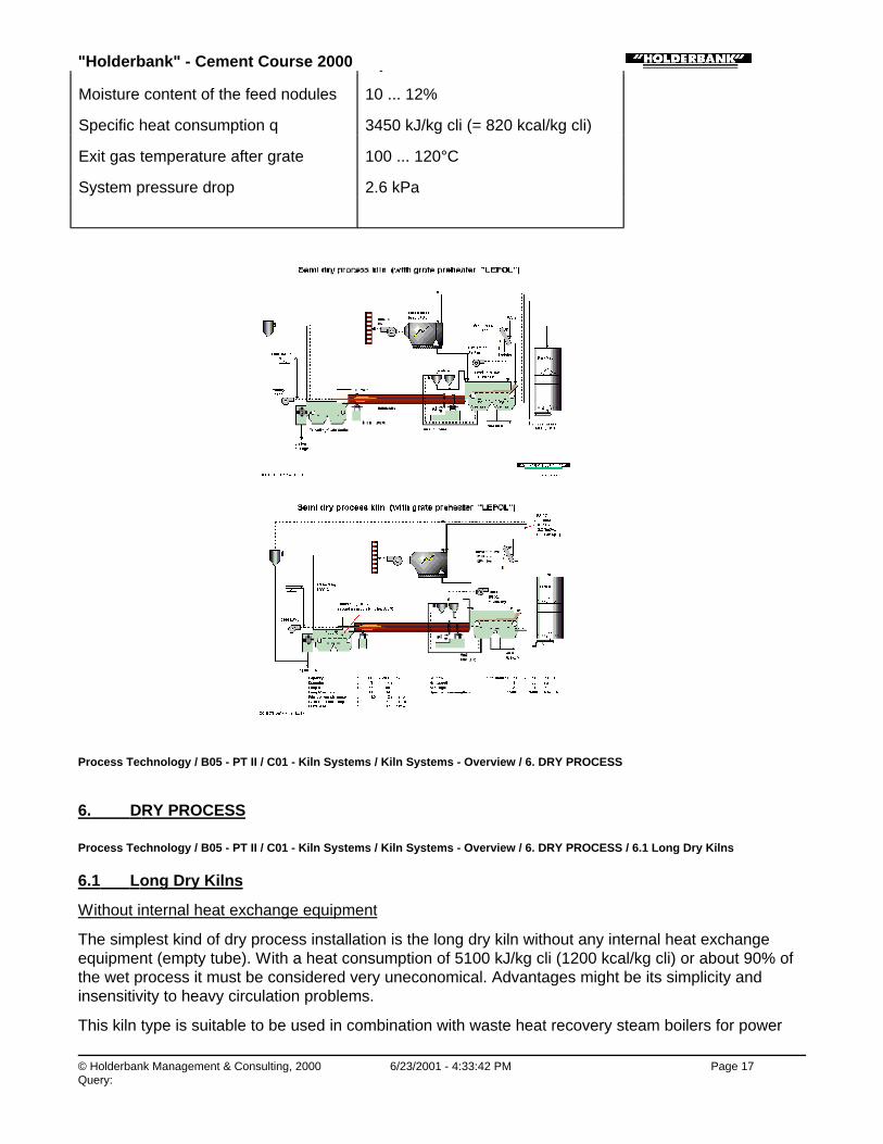
The only successfully working travelling grate pre-heater was available from Polysius and becameknown under the name LEPOL system (American licensee: Allis-Chalmers, ACL system).
This principle sketch shows a LEPOL kiln fed with nodules made out of dry raw meal. LEPOL kilns builtafter 1945 are equipped with two-pass grates; i.e. the exhaust gas is led twice through the nodule bedfrom top to bottom:
The hot kiln gas passes first through a bed of dry and preheated nodules and subsequently, after anintermediary dedusting once again trough a layer of moist incoming nodules. It is believed that thenodules survive throughout the process resulting in a clinker with very uniform size.
Furthermore, dust loads in the kiln atmosphere and dust emission out of the system are low. Thenodules on the grate let only pass the fine dust while the coarse particles are retained.
In cases of increased trace compound concentrations (especially alkali) in the raw material, the finedust separated in the electrostatic precipitator is largely enriched with them. Only a small amount ofdust has to be discarded to reduce the balance of these compounds in the kiln system. This effectmakes the LEPOL kiln quite suitable to produce a low alkali clinker with rather low heat consumption.For this reason, it has been chosen in many cases, particularly in the USA.
The following limits and disadvantages have to be considered:
• Only raw materials with good plastic properties can be used (semi-wet: filter cake nodules -> good filtration properties are required)
• The grate chain is subject to wear.
• Uneven temperature distribution across the grate can cause difficulties.
• Additional theoretical heat consumption due to the water content of the feed (partiallycompensated by a low exit gas temperature).
• Exhaust gases cannot be used in drying and grinding systems.
Characteristic data of a semi-dry grate pre-heater systems:
Feed nodules made from dry raw meal
"Holderbank" - Cement Course 2000
© Holderbank Management & Consulting, 2000 6/23/2001 - 4:33:42 PM Page 17Query:
Feed nodules made from dry raw meal
Moisture content of the feed nodules 10 ... 12%
Specific heat consumption q 3450 kJ/kg cli (= 820 kcal/kg cli)
Exit gas temperature after grate 100 ... 120°C
System pressure drop 2.6 kPa
Process Technology / B05 - PT II / C01 - Kiln Systems / Kiln Systems - Overview / 6. DRY PROCESS
6. DRY PROCESS
Process Technology / B05 - PT II / C01 - Kiln Systems / Kiln Systems - Overview / 6. DRY PROCESS / 6.1 Long Dry Kilns
6.1 Long Dry Kilns
Without internal heat exchange equipment
The simplest kind of dry process installation is the long dry kiln without any internal heat exchangeequipment (empty tube). With a heat consumption of 5100 kJ/kg cli (1200 kcal/kg cli) or about 90% ofthe wet process it must be considered very uneconomical. Advantages might be its simplicity andinsensitivity to heavy circulation problems.
This kiln type is suitable to be used in combination with waste heat recovery steam boilers for power

"Holderbank" - Cement Course 2000
© Holderbank Management & Consulting, 2000 6/23/2001 - 4:33:46 PM Page 18Query:
generation. In that case, the waste heat contained in the hot kiln exhaust gases is further used toproduce valuable energy.
Characteristic kiln data:
Heat consumption q 4500 ... 6000 kJ/kg cli (1075 ... 1430 kcal/kg cli)
Kiln gas exit temperature 450° ... 500°C
System pressure drop 0,5 ... 1,0 kPa
With internal heat exchange equipment
Long dry kilns with internal heat exchange equipment (chains or crosses from steel or ceramicmaterial) represent a more economical solution. Heat consumption of 4200 kJ/kg or even less can beachieved. Other typical operating figures are contained in annex 10.
Characteristic kiln data:
Heat consumption q 3800 ... 4500 kJ/kg cli (910 ... 1075 kcal/kg cli)
Kiln gas exit temperature 400° ... 450°C
System pressure drop 1,0 ... 1,5 kPa
Process Technology / B05 - PT II / C01 - Kiln Systems / Kiln Systems - Overview / 6. DRY PROCESS / 6.2 Raw Meal SuspensionPreheater Kilns
6.2 Raw Meal Suspension Preheater Kilns
Process Technology / B05 - PT II / C01 - Kiln Systems / Kiln Systems - Overview / 6. DRY PROCESS / 6.2 Raw Meal SuspensionPreheater Kilns / 6.2.1 General
6.2.1 General
During the last thirty years, the suspension preheater kiln became the dominant clinker manufacturingsystem. This system is fed by dry raw meal that is preferably prepared in a grinding and drying plant,using the kiln waste gases as a drying medium. This ground and dried raw meal is homogenised andthen fed to the preheater where it is suspended in the kiln gas flow, where an extremely effective heattransfer takes place. More information is contained in the special section “Suspension Preheaters”.
Process Technology / B05 - PT II / C01 - Kiln Systems / Kiln Systems - Overview / 6. DRY PROCESS / 6.2 Raw Meal SuspensionPreheater Kilns / 6.2.2 One and two Stage Cyclone Pre-heater Kilns
6.2.2 One and two Stage Cyclone Pre-heater Kilns
Characteristic kiln data:
one stage: Heat consumption q 3750 ... 4000 kJ/kg cli (900 ... 950 kcal/kg cli)
Kiln gas exit temperature 400° ... 500°C
System pressure drop 1,5 ... 2,5 kPa

"Holderbank" - Cement Course 2000
© Holderbank Management & Consulting, 2000 6/23/2001 - 4:33:46 PM Page 19Query:
two stages: Heat consumption q 3500 ... 3750 kJ/kg cli (850 ... 900 kcal/kg cli)
Kiln gas exit temperature 400° ... 450°C
System pressure drop 1,5 ... 2,5 kPa
Process Technology / B05 - PT II / C01 - Kiln Systems / Kiln Systems - Overview / 6. DRY PROCESS / 6.2 Raw Meal SuspensionPreheater Kilns / 6.2.3 Four Stage Cyclone Pre-heater Kilns
6.2.3 Four Stage Cyclone Pre-heater Kilns
Until the mid 1980s, this arrangement belong to the systems with the lowest fuel consumption. It wasoffered in several configurations with capacities up to 4500 t/d, most of them being combinations ofsingle or twin cyclone stages.
The kiln exit gas includes still enough heat to dry raw material up to moisture content of 8% if the mill isrunning during all the kiln operation time. From this point of view, the remaining relatively high exit gastemperature cannot be considered fully as a loss, because it can substitute an auxiliary firing for rawmaterial drying.
The preheater system is installed in a steel or concrete tower with a height of about 60 to 120 m (6stages) above the kiln inlet, depending on capacity and concept.
The four to six stages preheater is most susceptible to circulation problems at presence of excessiveconcentration of circulation compounds causing clogging problems in the pre-heater system.
The sketch shows a conventional four stage cyclone preheater system. In the 1970’s, production lineswith more than approx. 2000 t/d had to be built with two parallel preheater strings. Today, one-stringinstallations are possible for up to 4000 t/d.
Characteristic operating figures of 4-stage pre-heater kilns:
Heat consumption q
small units 3350 ... 3550 kJ/kg cli(= 800 ... 850 kcal/kg cli)

"Holderbank" - Cement Course 2000
© Holderbank Management & Consulting, 2000 6/23/2001 - 4:33:48 PM Page 20Query:
(= 800 ... 850 kcal/kg cli)
large units 3150 ... 3350 kJ/kg cli(= 750 ... 800 kcal/kg cli)
kiln exit gas temperature 320° ... 350°C
kiln exit gas volume approx. 1,5 Nm3/kg cli
System pressure drop 4 ... 6 kPa
Dust loss relative to clinker 8 ... 15%
Transition chamber
kiln gas temperature approx. 1100°C
Material temperature approx. 800°C
Process Technology / B05 - PT II / C01 - Kiln Systems / Kiln Systems - Overview / 6. DRY PROCESS / 6.2 Raw Meal SuspensionPreheater Kilns / 6.2.4 Precalciner Kilns
6.2.4 Precalciner Kilns
For larger production capacities, a larger portion of the pyroprocess had to be relocated out of therotary kiln in order to maintain reasonable kiln diameters without excessive thermal load of the burning

"Holderbank" - Cement Course 2000
© Holderbank Management & Consulting, 2000 6/23/2001 - 4:33:52 PM Page 21Query:
zone.
The process of dissociation of CO2 (calcination) is suitable to take place in a static reactor outside ofthe rotary kiln. Of the total heat consumption, 60 to 65% are required to achieve about 90% ofcalcination. 100% calcination must be avoided because clogging problems will seriously disturb kilnoperation (beginning of clinker formation).
The development of this reactor started with a secondary firing in the kiln riser duct sufficient for 35 to40% calcination of the meal, combustion air still pulled through the kiln tube (=air through). It wastherefore referred to as precalciner (PC) type AT. Only when hot cooler air (= tertiary air) for the PCfuel (= secondary fuel) was taken to the calciner in a separate duct, the so called tertiary air duct, thefull benefit of this technology could be used. Today, only this type called PC-AS (=air separate) isconsidered a real precalciner. The elements of a precalciner kiln system are explained in the sketch.
The strongest boost of calciner development was in the seventies in Japan, initiated by the demand forvery large units exceeding the potential of conventional kilns with suspension preheaters. Onlyprecalciner technology makes today’s largest units of 10’000 t/d possible.
Two process alternatives of precalciner are used:
• in-line calciner (calciner installed in kiln gas flow)
• separate-line calciner (calciner not passed by kiln gases)
More details on calciner technology are contained in a separate section.
The operating data are very close to the ones of the corresponding preheater kiln system. In-linecalciners have a tendency to higher gas exit temperature and system pressure drop; however, modernunits are equipped with 5 or 6 preheater stages to compensate for this.
Characteristic operating data of 4 to 6 stage precalciner kilns:
Heat consumption q
small units, 4 stage SP 3350 ... 3550 kJ/kg cli(= 800 ... 850 kcal/kg cli)
large units, 5 stage SP 2900 ... 3200 kJ/kg cli(= 700 ... 800 kcal/kg cli)
SP exit gas temp. 6 to 4 st. SP 290° ... 370°C
SP exit gas volume approx. 1.3 to 1.5 Nm3/kg cli
System pressure drop 4 ... 6 kPa
Dust loss relative to clinker 8 ... 15%
Transition chamber:
kiln gas temperature approx. 1100°C
Material temperature approx. 800°C

"Holderbank" - Cement Course 2000
© Holderbank Management & Consulting, 2000 6/23/2001 - 4:33:52 PM Page 22Query:
More data of precalciner kiln systems are shown in the section “Precalciners”.
HEAT BALANCE
WET / SEMI-DRY / 4-ST. PREHEATER / 5-ST. PREHEATER-PRECALCINER
WET PROCESS SEMI-DRYLEPOL
4-STAGE SP 6-STAGE SP-PC
Input kJ/kg cli % kJ/kg cli % kJ/kg cli % kJ/kg cli %
Fuel kiln combustion 5560 96.7% 3343 97.6% 3150 97.7% 1180 39.2%
sensible heat 25 0.4% 15 0.4% 13 0.4% 5 0.2%
Fuel PC combustion 0 0.0% 0 0.0% 0 0.0% 1775 58.9%
sensible heat 0 0.0% 0 0.0% 0 0.0% 8 0.3%
Kiln feed sensible heat 25 0.4% 30 0.9% 54 1.7% 45 1.5%
sensible heat ofwater
73 1.3% 17 0.5% 0 0.0% 0 0.0%

"Holderbank" - Cement Course 2000
© Holderbank Management & Consulting, 2000 6/23/2001 - 4:33:56 PM Page 23Query:
water
Insufflated air (PA, cooler) 67 1.2% 20 0.6% 6 0.2% 0 0.0%
Total inputs 5750 100% 3425 100% 3223 100% 3013 100%
Output kJ/kg cli % kJ/kg cli % kJ/kg cli % kJ/kg cli %
Heat of formation 1750 30.4% 1750 51.1% 1750 54.3% 1750 58.1%
Water evaporation 2370 41.2% 506 14.8% 13 0.4% 8 0.3%
Exhaust gas sens. heat 754 13.1% 314 9.2% 636 19.7% 553 18.4%
Exhaust gas dust sens.heat
25 0.4% 21 0.6% 18 0.6% 29 1.0%
Clinker 59 1.0% 50 1.5% 63 2.0% 83 2.8%
Cooler waste air 100 1.7% 276 8.1% 423 13.1% 288 9.6%
Radiation and convection :
- Preheater 0 0.0% 160 4.7% 77 2.4% 60 2.0%
- Precalciner (or bottomstage)
0 0.0% 0 0.0% 20 0.6% 20 0.7%
- Kiln (+tertiary air duct) 530 9.2% 200 5.8% 200 6.2% 200 6.6%
- Cooler 10 0.2% 92 2.7% 10 0.3% 10 0.3%
Water cooling 0 0.0% 42 1.2% 0 0.0% 0 0.0%
Other outputs 0 0.0% 0 0.0% 0 0.0% 0 0.0%
Rest 152 2.6% 14 0.4% 13 0.4% 12 0.4%
Total outputs 5750 100% 3425 100% 3223 107% 3013 100%

"Holderbank" - Cement Course 2000
© Holderbank Management & Consulting, 2000 6/23/2001 - 4:33:57 PM Page 24Query:
HISTORICAL DEVELOPMENT Annex 1
The word cement is more than 2000 years old, but impure lime has been used much longer as abuilding material. It is historically established, that the Phoenicians used a pozzolanic lime about 700B.C. and also the Romans produced some sort of cement or hard burned lime. From the medievalages, it is known that in Holland a type of hydraulic cement was formed out of lime and tuff in domeshaped kilns.
Our cement, as we know it today, is now more than 200 years old, “invented” by the Englishman JohnSmeaton in 1756. It was burned in bottle kilns. The better known inventor of Portland cement wasJoseph Aspdin, who patented his burning process in 1824. He also used dome kilns of approx. 36 ftheight and 17 ft diameter with a production of 90 bbl (= 15 t) per charge, each of which took severaldays to produce. Fuel consumption was 50% of clinker weight in coal which corresponds to 15’500kJ/kg cli (= 3’700 kcal/kg cli).
In 1880 an important step forward was made with the development of the continuously working shaftkiln, which had a much better heat economy. An example of such a kiln was the “DietzscheEtagenofen” which is shown in Annex 1.
From 1877 experiments have been conducted with rotary kilns. In 1897 Hurry and Seaman developedthe first successfully operating unit of this type in America.
These first rotary kilns were wet process kilns with a daily capacity of 50 to 100 tons. Their heatconsumption was again very high (about 30% of clinker in coal = 9’500 kJ/kg cli) and they had anincredible dust emission (usually more than one third of the whole production). In order to decreaseheat consumption, chain systems were installed in wet kilns to improve heat transfer during drying.Behind long dry kilns, waste heat steam boilers were arranged for the same purpose.
It took almost another 30 years, before a further substantial reduction of heat consumption could beachieved by reducing the water content of the feed and by a better heat exchange in the preheating acalcining zone. In 1930 an officer of the army of the tsar, Dr. Lellep, took an important step in thisdirection. He developed the travelling grate pre-heater, which is fed with moist nodules. This inventionwas taken over by Polysius and got the name LEPOL kiln. Some years later, there was a Czech patentof a cyclone raw meal pre-heater, and in 1953 Kloeckner-Humboldt-Deutz AG in Germany installedthe first suspension pre-heater system for raw meal. This type of kiln now became dominantbecause of its heat economy and nowadays other systems are only chosen in special cases. In formeryears, the main reason for the selection of the wet process was, that effective homogenisation of

"Holderbank" - Cement Course 2000
© Holderbank Management & Consulting, 2000 6/23/2001 - 4:33:58 PM Page 25Query:
ground raw material was not possible except in the form of slurry. In developing special techniques fordry material homogenisation such as mix beds, mixing chamber silos etc., this factor could beeliminated.
Utilising a rather old idea, since about 1966 especially Japanese cement machine manufacturers havedesigned several successfully working precalcining kiln systems. Calcination is already done in astationary calciner system, where secondary firing is installed. By this means, it is possible to designkiln systems with a comparatively small rotary part diameter but a very large capacity up to more than10’000 t/d.
Kiln systems built after 1990 include 6-stage preheaters with up to 4000 t/d per string, pure aircalciners, designed for a variety of fuels and emission control. Using modern low primary air burners,low pressure drop cyclone designs and high recuperation efficiency coolers allow further reduction ofheat and power consumption.

"Holderbank" - Cement Course 2000
© Holderbank Management & Consulting, 2000 6/23/2001 - 4:33:58 PM Page 26Query:
Process Technology / B05 - PT II / C01 - Kiln Systems / Rotary Kilns
Rotary KilnsU. GasserPT 98/14362/E
1. General
2. Kiln Dimensioning
3. Mechanical Aspects of Rotary Kilns
3.1 Riding Ring Fixation, Kiln Shell Ovality
3.2 Kiln Seals
3.2.1 Kiln Inlet Seal
3.2.2 Kiln Outlet Seal
3.3 Kiln Drive

"Holderbank" - Cement Course 2000
© Holderbank Management & Consulting, 2000 6/23/2001 - 4:33:59 PM Page 27Query:
SUMMARY
After over 100 years, the rotary kiln is used in all cement plants for clinker production.
The following properties made it superior to other principles:
♦ suitable to cope with high temperatures
♦ easy to be lined with refractory bricks due to its shape
♦ material transport behaviour
♦ tight to ambient
♦ mechanically relatively simple
♦ large units possible
The rotary kiln must be designed for process, combustion and mechanical requirements.
♦ Characteristic figures: ♦ Length L [m] , diameter D [m] and their ratio L/D[-]
♦
♦ ♦ Slope [°], speed range [min-1] and drive [kWh] ♦
♦ Dimensioning criteria: ♦ Volume load ♦ [t/(d m3)]
♦ ♦ Burning zone load ♦ [t/(d m2)]
♦ ♦ Thermal burning zone load ♦ [MW/m2]
♦
♦ Important mechanical features are:
♦ riding ring fixation
♦ roller station / alignment
♦ seals at inlet and outlet
♦ drive
♦
♦ With modern precalciner technology, outputs exceeding 10’000 t/d per kiln are possible withdiameters still below the 6.5 m of the largest wet kilns.
♦ There is a trend towards short L/D kilns with only two piers mainly because of lower investment.
Process Technology / B05 - PT II / C01 - Kiln Systems / Rotary Kilns / 1. GENERAL
1. GENERAL
Today, all clinker producing installations of industrial size use a rotary kiln. The rotary kiln is still theonly feasible way to manage this high temperature process with process material of varying behaviour.
One exception is the vertical shaft kiln still used in some parts of the world, e.g. China, however, for
"Holderbank" - Cement Course 2000
© Holderbank Management & Consulting, 2000 6/23/2001 - 4:33:59 PM Page 28Query:
small unit capacities only. The other exceptions are few pilot installations based on sintering in afluidized bed reactor.
Like many other great ideas, the rotary kiln was invented towards the end of the 19th century and hasfound application in many different industries. In 1987, Hurry and Seaman in the USA developed thefirst successfully working rotary kiln to produce cement clinker.
The first rotary cement kilns were using the wet process with one very long kiln tube, making it thedominating single piece of equipment of a plant. With technological progress, the kiln sections used forfor drying, heating-up and calcining have gradually been replaced by other types of equipment, therotary kiln remains to be the most suitable type of machine for the clinkerization process.
The rotary kiln has to satisfy three types of requirements:
Combustion: as a combustion chamber for burning zonefuel
Process: as a reactor for the clinker burning process (→ retention time)
as a material conveyor (→ slope, speed)
Mechanical: stability of shape, carrying load, thermalflexibility, tightness
Remarks:
♦ Even though the rotary kiln is a relatively simple piece of equipment, nobody has developed acomplete theoretical/mathematical model of its behaviour and process which would allow correctprocess simulation and equipment design.
♦ The rotary kiln is still the “heart” of the entire production line. Its OEE (overall equipment efficiency)depending mainly on hourly output and availability, is decisive for the success of a plant.
♦ The rotary kiln is designed to operate 24 hours a day, and the rest of the equipment upstream anddownstream has to follow.
♦ Being a major cause for production cost (mechanical maintenance, refractories), a well managedkiln is vital for a successful plant.
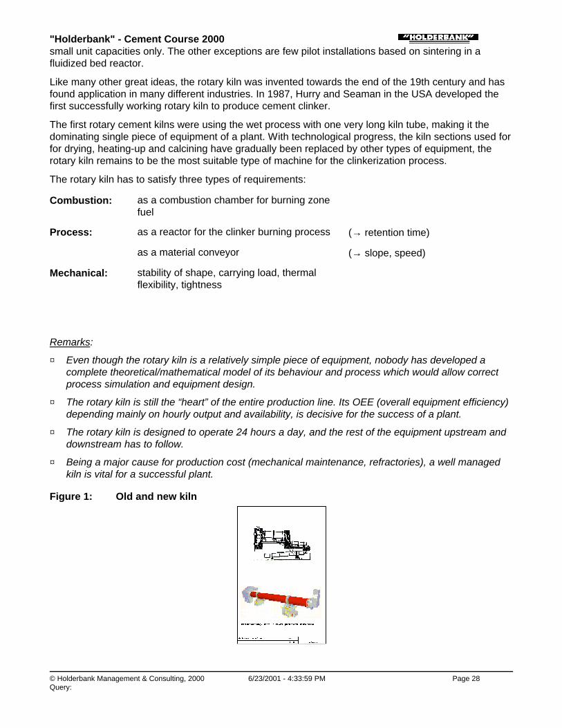
Figure 1: Old and new kiln

"Holderbank" - Cement Course 2000
© Holderbank Management & Consulting, 2000 6/23/2001 - 4:34:00 PM Page 29Query:
Process Technology / B05 - PT II / C01 - Kiln Systems / Rotary Kilns / 2. KILN DIMENSIONING
2. KILN DIMENSIONING
The kiln dimensions are defined with diameter D (for kilns with different diameter: burning zone D) andlength L:
L [m] and D [m] resp. L/D [m]
♦ For cement kilns, the actual L/D ratio range is: from 40 (for long wet kilns) to 11 (for modern short kilns with precalciner)
♦ The diameter D is the inner diameter Di of the kiln (steel-) shell.
♦ Process technological dimensioning of a kiln is based on empirical figures and experience fromexisting installations
One limiting factor for the diameter is the mechanical stability of the ‘arch’ of the brick lining. Maximumdiameters which can be safely realised with standard size bricks are about 6,5 m. The largest kiln inthe “Holderbank” group is 232 m (wet process, 3750 t/d).
The following process technological dimensioning criteria are mostly used:
Specific Volume Load
VolumeKiln NetProduction Clinker [t/(d m3)]
Specific Zone Load
Section Cross Zone Burning NetProduction Clinker [t/(d m2)]
Thermal Burning Zone Load
Section Cross Zone Bruning NetInput Heat Zone Burning [MW/m2)]
Specific volume load and thermal burning zone (BZ) load have no physical significance. They aremerely defined to make existing installations comparable.
The specific load is indirectly a gas velocity, because generating a certain amount of thermal energy byfuel combustion results in a proportional gas flow which can be calculated.
The thermal BZ load per cross section is considered the limiting factor for a modern kiln system. For acertain length/diameter ratio, which is typical for each kiln type, the thermal BZ load it is proportional tothe heat load on the inside of the lining surface which is one of the main influencing factor on brick life.The limit usually respected is:

"Holderbank" - Cement Course 2000
© Holderbank Management & Consulting, 2000 6/23/2001 - 4:34:00 PM Page 30Query:
Max. Thermal BZ Load = 6 MW/m2 (=5.16 x 10⁶ kcal/m2 h)
Other absolute limiting values of all the three factors are not known. Each supplier seems to have hisown rules of kiln dimensioning. Since no theoretical formulas have been derived to calculate the kilnsize on an analytical basis, it is possible, that the present limits of the dimensioning criteria may besurpassed even for the conventional processes.
Figure 2: Long and short L/D kilns
Process Technology / B05 - PT II / C01 - Kiln Systems / Rotary Kilns / 3. MECHANICAL ASPECTS OF ROTARY KILNS
3. MECHANICAL ASPECTS OF ROTARY KILNS
The following aspects of kiln mechanical design are relevant for the process:
♦ Riding ring fixation, kiln shell ovality
♦ Kiln seals
♦ kiln drive
♦ refractory lining (separate paper)
♦ nose ring (covered in “refractory lining”)
Process Technology / B05 - PT II / C01 - Kiln Systems / Rotary Kilns / 3. MECHANICAL ASPECTS OF ROTARY KILNS / 3.1 RidingRing Fixation, Kiln Shell Ovality
3.1 Riding Ring Fixation, Kiln Shell Ovality
A rotary kiln should be designed as cheaply as possible, yet it must still be rigid to guarantee minimumwear of the lining. This requirement can be met, if the deformation of the kiln shell is reduced to atolerable limit.
The parameter expressing shell deformation at a certain point is the kiln shell ovality
ω:

"Holderbank" - Cement Course 2000
© Holderbank Management & Consulting, 2000 6/23/2001 - 4:34:01 PM Page 31Query:
Definition of
ω:
ω=2 (a - b) with 2a and 2b as the main axis of an ellipse
Investigations have shown, that generally a maximum relative ovality ω
of0,3% is allowed This ovality may be subdivided into two amounts:
a) Ovality of the riding ring 3 cm due to external forces allowed value:
%2.0<=drω
a) Ovality of the kiln shell due to deformations by its own weight in loose riding rings and due toincreased temperature.
The following two requirements must be met to keep the kiln ovality within the tolerable limits:
♦ The riding rings must be rigid enough
♦ The clearance between the ring shoes and the riding ring should be minimum during operation. Thefollowing table shows some practical values:
Riding Ring No. 1 2 3 4
Clearance during operation [mm] 3-4 3-4 4-6 5-6
maximum [mm] 10-15
Riding rings with splined fixation provide much better support of the kiln shell. Because the kiln shell islaterally suspended in adequately designed carrying bars, ovality is much reduced resulting innoticeably better brick life.
Such systems are currently available from Polysius and FLS, the latter one is lso offered as retrofit.Splined tire fixations are integral part of gearless kiln drive systems.
Figure 3: Tire fixations

"Holderbank" - Cement Course 2000
© Holderbank Management & Consulting, 2000 6/23/2001 - 4:34:01 PM Page 32Query:
Process Technology / B05 - PT II / C01 - Kiln Systems / Rotary Kilns / 3. MECHANICAL ASPECTS OF ROTARY KILNS / 3.2 Kiln Seals
3.2 Kiln Seals
In order to avoid the danger of hot gases and dust leaking into the atmosphere, the entire kiln systemis operated at negative pressure. The pressure profile starts at ambient (grate cooler: above first grate,satellite and tube cooler: fresh air inlet) and becomes increasingly negative towards the kiln induceddraft (ID) fan.
Instead of leaking out from within the process, there is now a problem with ambient air being suckedinto the system, called false air. Depending on the point of entry, false air has different undesiredeffects. That is why a lot of effort is made to keep process systems tight.
Process Technology / B05 - PT II / C01 - Kiln Systems / Rotary Kilns / 3. MECHANICAL ASPECTS OF ROTARY KILNS / 3.2 Kiln Seals/ 3.2.1 Kiln Inlet Seal
3.2.1 Kiln Inlet Seal
The kiln inlet seal (inlet: referring to material flow) is at point with negative pressure of less than 10mmWG (modern 2-support kilns) up to 100 mmWG (long wet kilns with chains).
Modern kilns with low suction have high temperatures (up to 1300°C) instead.
False air entering the system causes
♦ Additional gas to be handled by kiln ID fan and dedusting system
♦ Unnecessary cooling of hot process gases reducing value of heat
Kiln inlet seals:
♦ Sealing force by pneumatic cylinders (pneumatic); sealing-rings
♦ Sealing force by coil springs/levers or weights (mechanical); sealing-segments
♦ Sealing force by leaf springs and rope with weight; lamella (fish scale)
Kiln inlet seals must be equipped with a dust return scoop ring to avoid spillage of kiln feed.
Note:
The inlet seal is designed to seal against cold fresh air from outside, but it can be damaged if it mustseal hot gas from inside to ambient in case of system overpressure! (this happens sometimes duringthe heating-up phase)

"Holderbank" - Cement Course 2000
© Holderbank Management & Consulting, 2000 6/23/2001 - 4:34:02 PM Page 33Query:
Process Technology / B05 - PT II / C01 - Kiln Systems / Rotary Kilns / 3. MECHANICAL ASPECTS OF ROTARY KILNS / 3.2 Kiln Seals/ 3.2.2 Kiln Outlet Seal
3.2.2 Kiln Outlet Seal
With grate and tube coolers, the kiln outlet seal is installed between kiln head and rotary kiln wherepressure should be slightly negative. Kiln outlet seals used with grate coolers must be designed tocope with pressure pulsation with occasional positive pressure. Outlet seal and nosering (brickretainer) with cooling air fan can be considered one system.
Here, the loss generated by false air reduces recuperation from the clinker cooler. Cold ambient airreplaces hot secondary air from the cooler which has to be vented.
Outlet seals designed specifically for this application of the following type are available:
♦ Pneumatic
♦ Mechanical
♦ Lamella (fish scale)
♦ Labyrinth (outdated)
With planetary coolers, false air reduces the amount of cooling air resulting in higher clinkertemperatures. The outlet seal is smaller, at lower temperature and negative pressure only.
Figure 4: Kiln seals
Process Technology / B05 - PT II / C01 - Kiln Systems / Rotary Kilns / 3. MECHANICAL ASPECTS OF ROTARY KILNS / 3.3 Kiln Drive
3.3 Kiln Drive
Kiln drives are designed for speeds between 1.0 and 4.0 min-1, depending on slope, process and kilndimensions. Long wet kilns are typically operated at the low end of this speed range where some newhigh performance kilns (short L/D with precalciners) are running at the upper end.
For over 10 years, rotary kilns have been driven by girth and pinion type drives. Decisive for theirperformance are:
♦ Correct dimensioning
♦ Correct alignment (even load distribution on the flanks of the teeth; no peaks)
♦ Adequate lubrication system and lubricant quality
"Holderbank" - Cement Course 2000
© Holderbank Management & Consulting, 2000 6/23/2001 - 4:34:02 PM Page 34Query:
With the new two support short kilns (L/D < 13) with long overhangs, kiln shell deformation and burningzone much closer to the drive, it became more difficult to ascertain correct alignment. Because of thedetermined load distribution on two piers, it became possible to avoid the girth drive by using the kilnrollers to transfer the torque to the riding ring: the gearless drive (=friction drive) was introduced. It iscurrently available from Polysius (POLRO) and FLS-Fuller (ROTAX).
The following elements are part of this system:
• Two supports for defined load on the driven tire
• Splined tire fixation for safe torque transmission to the shell
• Self-aligning rollerstation
for linear load pattern between roller and tire (friction)
Today, there are only few kilns with friction in operation; the first one was Lägerdorf 11 by Polysius.Detail optimization and long term experience are yet to be awaited.
Most systems have hydraulic drives for two rollers. This provides smooth operation, but is expensive,rather complex (hydraulic unit) and has higher power consumption. Electric direct drive of only oneroller has been installed in one case.
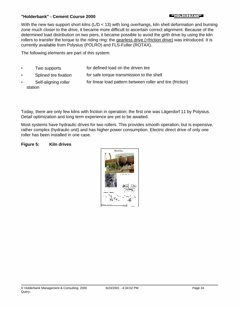
Figure 5: Kiln drives

"Holderbank" - Cement Course 2000
© Holderbank Management & Consulting, 2000 6/23/2001 - 4:34:03 PM Page 35Query:
Process Technology / B05 - PT II / C01 - Kiln Systems / Suspension Preheater
Suspension PreheaterU. GasserPT 98/14363/E
1. General
1.1 History
1.2 Trend
2. Heat Exchange in a Suspension Preheater
2.1 Counter-Current Heat Exchange (Shaft Stage)
2.2 Co-Current Heat Exchange (Cyclone Stage)
2.3 Thermodynamic Limits
3. Preheater Types
3.1 Preheaters with Shaft Stages
3.1.1 Pure shaft preheaters:
3.1.2 Hybrid preheaters:
3.2 Preheaters with Cyclone Stages
3.3 Economical Number of Stages for Cyclone Preheaters
3.4 Minimum Gas Velocity
4. Design Features of Preheater-Cyclones
4.1 General
4.2 Dust Cycles
4.3 Features
4.3.1 Splash Box
4.3.2 Dip Tube (Immersion Tube, Vortex Finder, Thimble)
4.3.3 Meal Flap
4.3.4 Cyclone Shapes
5. Preheater Operation
5.1 Operating Problems of Suspension Preheaters
5.1.1 Circulation Phenomena.
6. New Developments
6.1 Horizontal Cyclone
6.2 TRS

"Holderbank" - Cement Course 2000
© Holderbank Management & Consulting, 2000 6/23/2001 - 4:34:03 PM Page 36Query:
SUMMARY
Practically all modern kiln systems are equipped with a cyclone suspension preheater.
New installations include a precalciner with tertiary air duct, so that the preheater and precalciner havebecome one unit. However, the preheater has a specific task and is not principally connected to theprecalciner.
Modern low pressure drop cyclones are the result of a development which started in 1932.
♦ Shaft Preheaters:
• Counter-current heat exchange
• Limited production (around 1000 t/d)
• Disappointing heat exchange mainly due to poor meal distribution
♦ Hybrid preheaters:
• Combination of shaft and cyclone stages
• Bühler-Miag, Polysius, Prerov, Humboldt
• Shaft stages often replaced by cyclone stages
♦ Cyclone preheaters:
• Co-current heat exchange
• Successful concept, predominantly used
♦ Industrial installations of cyclone preheaters:
• Precalciner kiln with 4 to 6 cyclone stages (contemporary technology):∗ Large capacities possible > 10000 t/d∗ Up to 4000 t/d in 1 string∗ Heat consumption < 3000 kJ/kg possible (6 stages)∗ Sensitive to circulation phenomena (-> kiln gas bypass!)
• 4-stage cyclone pre-heater kiln (standard technology 1970 to 1980):∗ Cyclone for raw meal preheating∗ Large application world wide∗ Capacities of up to 4500 t/d technically possible∗ Heat consumption: 3150 to 3350 kJ/kg cli∗ Sensitive to circulation phenomena (-> kiln gas bypass!)
• 2-stage cyclone pre-heater kiln:∗ Less sensitive to circulating elements than 4-stage pre-heater∗ Higher heat consumption than pre-heater with more stages
♦ Most recent innovations:
• Horizontal cyclone for “low profile” preheaters (Polysius)
• Dip tube add-on RTS for 30% lower cyclone pressure drop
Process Technology / B05 - PT II / C01 - Kiln Systems / Suspension Preheater / 1. GENERAL
1. GENERAL
Process Technology / B05 - PT II / C01 - Kiln Systems / Suspension Preheater / 1. GENERAL / 1.1 History

"Holderbank" - Cement Course 2000
© Holderbank Management & Consulting, 2000 6/23/2001 - 4:34:04 PM Page 37Query:
1.1 History
With dry process, the heat exchange for heating up and calcination takes place between hot kiln gasand dry powder. Since the high dust losses from long dry kilns made it almost impossible to achieveacceptable heat consumption: other heat exchange principles had to be applied.
Since the temperature range to be covered is below 1000°C, where the meal behaves normally like drypowder, stationary reactors where the meal is in suspension with the hot gas can be used.
The first patent for a suspension preheater using four co-current cyclone stages was applied for in1932 and issued in 1934 by the patent office in Prague to a Danish engineer employed by FLS. Eventhough the concept was entirely described in the patent, it took another 20 years for industrialapplication in 1951 by the company Humboldt, now KHD.
Other developments using shaft stages have been abandoned and today, a suspension preheater isactually a cyclone preheater.
Process Technology / B05 - PT II / C01 - Kiln Systems / Suspension Preheater / 1. GENERAL / 1.2 Trend
1.2 Trend
All new kiln systems and the majority of the ones with start-up date after 1970 are equipped withcyclone pre-heaters. Gradually, older plants with wet kilns or long dry kilns are shut down for good dueto their age as well as their high specific production cost
The portion of world’s cement produced with kilns using suspension pre-heaters is still growing, as canbe seen by the development of the “Holderbank” plants. It looks as if it will exceed 95% one daybecause no feasible alternative solution changing this development is in sight.
In combination with pre-calciners, units of 10’000 t/d have been built using up to four strings, fivestages. Typically, 3500 t/d can be handled in one string, in a recent project even 4000 t/d have beenproposed.
Figure 1:
Figure 2:

"Holderbank" - Cement Course 2000
© Holderbank Management & Consulting, 2000 6/23/2001 - 4:34:04 PM Page 38Query:
Process Technology / B05 - PT II / C01 - Kiln Systems / Suspension Preheater / 2. HEAT EXCHANGE IN A SUSPENSION PREHEATER
2. HEAT EXCHANGE IN A SUSPENSION PREHEATER
Process Technology / B05 - PT II / C01 - Kiln Systems / Suspension Preheater / 2. HEAT EXCHANGE IN A SUSPENSION PREHEATER/ 2.1 Counter-Current Heat Exchange (Shaft Stage)
2.1 Counter-Current Heat Exchange (Shaft Stage)
The most efficient type of heat exchange is the counter-current principle. The flows of the heatreleasing media and the heat absorbing media are in opposite directions. This provides optimum thetemperature difference (=temperature gradient, in theory allowing almost complete heat exchange.
In case of a suspension preheater, where powder is suspended in a gas, the heat exchange takesplace in a “reactor” vessel where the hot gas enters from below and leaves at the top. The meal to bepreheated is fed at the top. The meal retention time depends on distribution across the gas flow andthe retention time, which is determined by the gas velocity.
In industrial installations, the heat exchange proved to be far below expected, because evendistribution of the meal was not achieved, particularly not with large units.
Process Technology / B05 - PT II / C01 - Kiln Systems / Suspension Preheater / 2. HEAT EXCHANGE IN A SUSPENSION PREHEATER/ 2.2 Co-Current Heat Exchange (Cyclone Stage)
2.2 Co-Current Heat Exchange (Cyclone Stage)
Co-current heat exchange takes place if both heat exchanging media flow in the same direction.Because of the rapidly decreasing temperature difference, the meal can never reach gas inlettemperature.
Good and reproducible results in industrial installations with this type lead to the predominance of thisprinciple in the cement industry. The heat exchanger is a gas duct with velocities from 10 to 20 m/s,equipped with good meal dispersion devices. The purpose of the cyclone is primarily to separate mealfrom gas, and not to exchange heat!
Process Technology / B05 - PT II / C01 - Kiln Systems / Suspension Preheater / 2. HEAT EXCHANGE IN A SUSPENSION PREHEATER/ 2.3 Thermodynamic Limits
2.3 Thermodynamic Limits
Regardless of the type of heat exchange, there is always a thermodynamic imbalance between hot
"Holderbank" - Cement Course 2000
© Holderbank Management & Consulting, 2000 6/23/2001 - 4:34:04 PM Page 39Query:
gases from kiln and calciner and cold raw meal. The heat contained available in the hot gas leaving therotary kiln exceeds the heat required for heating the meal to the temperature levels required forcalcination.
Another limit must be observed: Because the temperature gradient between gas and meal (T gas > Tmeal) must always be maintained, a higher calcination degree than 30% cannot be achieved withoutadditional heat input.
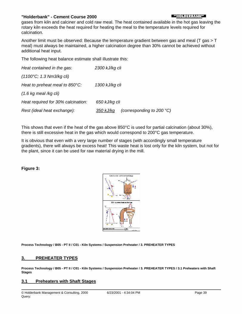
The following heat balance estimate shall illustrate this:
Heat contained in the gas: 2300 kJ/kg cli
(1100°C; 1.3 Nm3/kg cli)
Heat to preheat meal to 850°C: 1300 kJ/kg cli
(1.6 kg meal /kg cli)
Heat required for 30% calcination: 650 kJ/kg cli
Rest (ideal heat exchange): 350 kJ/kg (corresponding to 200 °C)
This shows that even if the heat of the gas above 850°C is used for partial calcination (about 30%),there is still excessive heat in the gas which would correspond to 200°C gas temperature.
It is obvious that even with a very large number of stages (with accordingly small temperaturegradients), there will always be excess heat! This waste heat is lost only for the kiln system, but not forthe plant, since it can be used for raw material drying in the mill.
Figure 3:
Process Technology / B05 - PT II / C01 - Kiln Systems / Suspension Preheater / 3. PREHEATER TYPES
3. PREHEATER TYPES
Process Technology / B05 - PT II / C01 - Kiln Systems / Suspension Preheater / 3. PREHEATER TYPES / 3.1 Preheaters with ShaftStages
3.1 Preheaters with Shaft Stages

"Holderbank" - Cement Course 2000
© Holderbank Management & Consulting, 2000 6/23/2001 - 4:34:05 PM Page 40Query:
The rather disappointing performance of the shaft stage made it virtually disappear from the market.Many hybrid preheaters were equipped with one or two cyclone stages replacing the shaft stage.
Shaft stages at the kiln inlet have the advantage to be less sensitive to build-ups. This could be anadvantage in cases where elevated sulfur input in the kiln system must be expected.
Several Suppliers built preheaters using shaft stages. Two groups can be distinguished:
Process Technology / B05 - PT II / C01 - Kiln Systems / Suspension Preheater / 3. PREHEATER TYPES / 3.1 Preheaters with ShaftStages / 3.1.1 Pure shaft preheaters:
3.1.1 Pure shaft preheaters:
Polysius: • GEPOL
• Self-supporting structure (no tower required)
• Vertical tube with restrictions
• For small capacities (up to ca. 1000 t/d)
ZAB Dessau: • Some applications in Eastern Europe
• Similar to GEPOL, but not self-supporting
• The Deuna plant had originally 4 ZAB shaft preheaters
Process Technology / B05 - PT II / C01 - Kiln Systems / Suspension Preheater / 3. PREHEATER TYPES / 3.1 Preheaters with ShaftStages / 3.1.2 Hybrid preheaters:
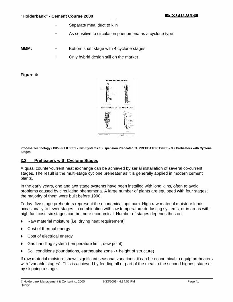
3.1.2 Hybrid preheaters:
Several suppliers used a combination of shaft and cyclone stages:
Polysius: • DOPOL preheater (first generation)
• The central swirl-pot (second lowest stage) was shaft stage
• Replaced by DOPOL 90 from 1990
• Gradually developed into a cyclone preheater
• Up to ca. 3000 t/d
Bühler-Miag: • Lowest stage was shaft stage
• Later often replaced by cyclone stage
Prerov: • One large shaft stage with dedusting cyclone
• Shaft stage selfsupporting
• Additional cyclone stage possible
"Holderbank" - Cement Course 2000
© Holderbank Management & Consulting, 2000 6/23/2001 - 4:34:05 PM Page 41Query:
• Additional cyclone stage possible
• Separate meal duct to kiln
• As sensitive to circulation phenomena as a cyclone type
MBM: • Bottom shaft stage with 4 cyclone stages
• Only hybrid design still on the market
Figure 4:
Process Technology / B05 - PT II / C01 - Kiln Systems / Suspension Preheater / 3. PREHEATER TYPES / 3.2 Preheaters with CycloneStages
3.2 Preheaters with Cyclone Stages
A quasi counter-current heat exchange can be achieved by serial installation of several co-currentstages. The result is the multi-stage cyclone preheater as it is generally applied in modern cementplants.
In the early years, one and two stage systems have been installed with long kilns, often to avoidproblems caused by circulating phenomena. A large number of plants are equipped with four stages;the majority of them were built before 1990.
Today, five stage preheaters represent the economical optimum. High raw material moisture leadsoccasionally to fewer stages, in combination with low temperature dedusting systems, or in areas withhigh fuel cost, six stages can be more economical. Number of stages depends thus on:
♦ Raw material moisture (i.e. drying heat requirement)
♦ Cost of thermal energy
♦ Cost of electrical energy
♦ Gas handling system (temperature limit, dew point)
♦ Soil conditions (foundations, earthquake zone -> height of structure)
If raw material moisture shows significant seasonal variations, it can be economical to equip preheaterswith “variable stages”. This is achieved by feeding all or part of the meal to the second highest stage orby skipping a stage.

"Holderbank" - Cement Course 2000
© Holderbank Management & Consulting, 2000 6/23/2001 - 4:34:05 PM Page 42Query:
Note: Numbering of stages is always from top to bottom: top stage = stage 1.
Exception: Polysius: bottom stage = stage 1
Figure 5:
Process Technology / B05 - PT II / C01 - Kiln Systems / Suspension Preheater / 3. PREHEATER TYPES / 3.3 Economical Number ofStages for Cyclone Preheaters
3.3 Economical Number of Stages for Cyclone Preheaters
For many years, the pressure drop across one preheater stage was up to 1,5 kPa (15 mbar). Thereason for the 4-stage pre-heater being so widely used is, that it represented an optimum betweeninvestment cost (structure height, foundation), pressure drop and heat consumption. . Theperformance of comparable systems built in about the same period are within a relatively narrow range.
About two third of the pressure drop of a stage occurs in the cyclone and depends on its shape/designand the size, the latter being the determining cost factor.
New cyclone designs are now on the market with only 0,5 to 1,0 kPa (5-10 mbar) pressure drop perstage. Considering increasing energy cost, it is justified to install 5 or 6 pre-heater stages for new ormodified kiln systems.
The following table indicated the estimated effect of a 5th and a 6th cyclone stage:
4 to 5st 5 to 6st
Heat consumption kJ/kg cli - 80 - 50
Exhaust gas temperature °C - 40 to -50 - 20 to -30
Exhaust gas quantity Nm3/kg cli - 0,03 - 0,015
Drying capacity in RM % H2O from 8 - 6,5 From 6,5 -5,5
Process Technology / B05 - PT II / C01 - Kiln Systems / Suspension Preheater / 3. PREHEATER TYPES / 3.4 Minimum Gas Velocity
"Holderbank" - Cement Course 2000
© Holderbank Management & Consulting, 2000 6/23/2001 - 4:34:06 PM Page 43Query:
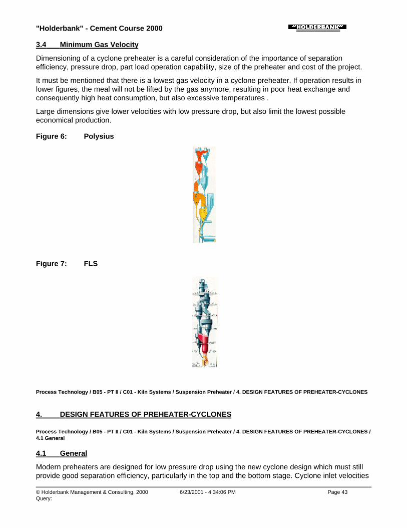
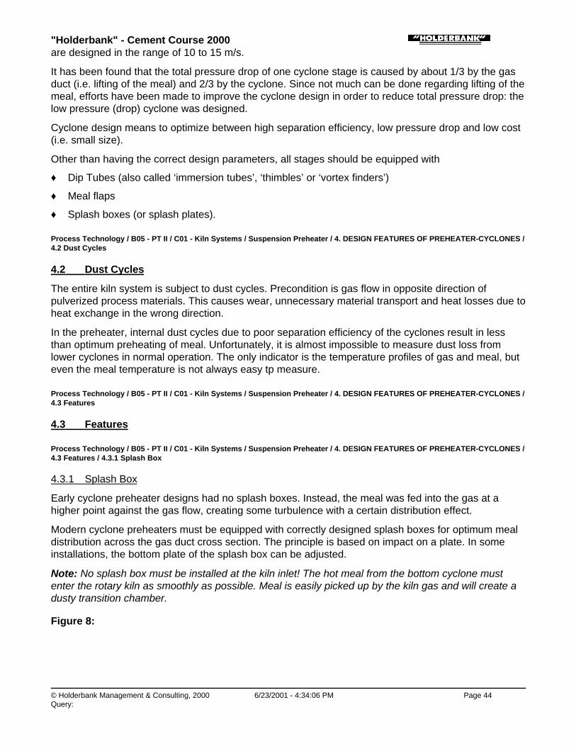
3.4 Minimum Gas Velocity
Dimensioning of a cyclone preheater is a careful consideration of the importance of separationefficiency, pressure drop, part load operation capability, size of the preheater and cost of the project.
It must be mentioned that there is a lowest gas velocity in a cyclone preheater. If operation results inlower figures, the meal will not be lifted by the gas anymore, resulting in poor heat exchange andconsequently high heat consumption, but also excessive temperatures .
Large dimensions give lower velocities with low pressure drop, but also limit the lowest possibleeconomical production.
Figure 6: Polysius
Figure 7: FLS
Process Technology / B05 - PT II / C01 - Kiln Systems / Suspension Preheater / 4. DESIGN FEATURES OF PREHEATER-CYCLONES
4. DESIGN FEATURES OF PREHEATER-CYCLONES
Process Technology / B05 - PT II / C01 - Kiln Systems / Suspension Preheater / 4. DESIGN FEATURES OF PREHEATER-CYCLONES /4.1 General
4.1 General
Modern preheaters are designed for low pressure drop using the new cyclone design which must stillprovide good separation efficiency, particularly in the top and the bottom stage. Cyclone inlet velocities
"Holderbank" - Cement Course 2000
© Holderbank Management & Consulting, 2000 6/23/2001 - 4:34:06 PM Page 44Query:
are designed in the range of 10 to 15 m/s.
It has been found that the total pressure drop of one cyclone stage is caused by about 1/3 by the gasduct (i.e. lifting of the meal) and 2/3 by the cyclone. Since not much can be done regarding lifting of themeal, efforts have been made to improve the cyclone design in order to reduce total pressure drop: thelow pressure (drop) cyclone was designed.
Cyclone design means to optimize between high separation efficiency, low pressure drop and low cost(i.e. small size).
Other than having the correct design parameters, all stages should be equipped with
♦ Dip Tubes (also called ‘immersion tubes’, ‘thimbles’ or ‘vortex finders’)
♦ Meal flaps
♦ Splash boxes (or splash plates).
Process Technology / B05 - PT II / C01 - Kiln Systems / Suspension Preheater / 4. DESIGN FEATURES OF PREHEATER-CYCLONES /4.2 Dust Cycles
4.2 Dust Cycles
The entire kiln system is subject to dust cycles. Precondition is gas flow in opposite direction ofpulverized process materials. This causes wear, unnecessary material transport and heat losses due toheat exchange in the wrong direction.
In the preheater, internal dust cycles due to poor separation efficiency of the cyclones result in lessthan optimum preheating of meal. Unfortunately, it is almost impossible to measure dust loss fromlower cyclones in normal operation. The only indicator is the temperature profiles of gas and meal, buteven the meal temperature is not always easy tp measure.
Process Technology / B05 - PT II / C01 - Kiln Systems / Suspension Preheater / 4. DESIGN FEATURES OF PREHEATER-CYCLONES /4.3 Features
4.3 Features
Process Technology / B05 - PT II / C01 - Kiln Systems / Suspension Preheater / 4. DESIGN FEATURES OF PREHEATER-CYCLONES /4.3 Features / 4.3.1 Splash Box
4.3.1 Splash Box
Early cyclone preheater designs had no splash boxes. Instead, the meal was fed into the gas at ahigher point against the gas flow, creating some turbulence with a certain distribution effect.
Modern cyclone preheaters must be equipped with correctly designed splash boxes for optimum mealdistribution across the gas duct cross section. The principle is based on impact on a plate. In someinstallations, the bottom plate of the splash box can be adjusted.
Note: No splash box must be installed at the kiln inlet! The hot meal from the bottom cyclone mustenter the rotary kiln as smoothly as possible. Meal is easily picked up by the kiln gas and will create adusty transition chamber.
Figure 8:

"Holderbank" - Cement Course 2000
© Holderbank Management & Consulting, 2000 6/23/2001 - 4:34:06 PM Page 45Query:
Process Technology / B05 - PT II / C01 - Kiln Systems / Suspension Preheater / 4. DESIGN FEATURES OF PREHEATER-CYCLONES /4.3 Features / 4.3.2 Dip Tube (Immersion Tube, Vortex Finder, Thimble)
4.3.2 Dip Tube (Immersion Tube, Vortex Finder, Thimble)
This integral element of the cyclone has a decisive influence on separation and pressure drop. Itmakes the gas to follow a 180 to 360° rotation thus creating the desired centrifugal force for theseparation effect.
In the colder upper stages (stage 1 to 3) it can be designed as simple extension of the outlet gas duct,made from steel plate. These upper stage dip tubes create usually no problems except when thepreheater gets overheated, e.g. during start-up. Then, the dip tube can collapse, causing excessivepressure drop.
In the hotter lower stages, mild steel ducts from one piece are not suitable. Several segmented designsmade from heat resistant steel or ceramic material (Hasle) are available on the market. It is standardtoday that all stages are equipped with dip tubes.
Note: It appears that some designs of segmented dip tubes have a tendency to unhook enablingindividual elements to drop and to block the cyclone outlet!
For older plants, installing a segmented dip tube in the lower stages is a optimization possibility whichis often applied.
Process Technology / B05 - PT II / C01 - Kiln Systems / Suspension Preheater / 4. DESIGN FEATURES OF PREHEATER-CYCLONES /4.3 Features / 4.3.3 Meal Flap
4.3.3 Meal Flap
In order to understand the purpose of the meal flap, the following two aspects must be mentioned:
♦ There is a pressure difference across a cyclone stage, i.e. between two subsequent cyclone gasoutlets (maintained by the ID fan).
♦ Without meal, there are two ways the gas can flow from one stage to the next: through gas ductand through meal duct
If there was an ideal kiln system, i.e. a system with 100% constant meal flow and never changingoperation parameters, the meal duct diameter could be designed for just the meal. The meal wouldthen fill the entire cross section, leaving no opening for the gas. In reality, there are fluctuations of mealand dropping build-ups, requiring oversized meal ducts.
It is the purpose of the meal flap to close the free cross section not used by the meal, to avoid gas

"Holderbank" - Cement Course 2000
© Holderbank Management & Consulting, 2000 6/23/2001 - 4:34:07 PM Page 46Query:
bypass. There are designs that open only when a certain weight pushes them open, thus creating mealfluctuations. Other designs (see figure) are adjustable so that they move only in case of meal peaks orlumps.
Not operational meal flaps cause heat loss and allow build-up formation in meal ducts(circulating elements)!
Process Technology / B05 - PT II / C01 - Kiln Systems / Suspension Preheater / 4. DESIGN FEATURES OF PREHEATER-CYCLONES /4.3 Features / 4.3.4 Cyclone Shapes
4.3.4 Cyclone Shapes
The separation efficiency of a cyclone gets better with longer dip tube and increasing distance betweenswirl (cylinder) and dust collecting cone, i.e. with high and slim shapes.
The top stage of preheaters is designed for high separation efficiency. In order to save height, mostsuppliers install twin cyclones with the drawback that meal and gas have to be split. There are a fewplants from FLS with only one top cyclone, avoiding this drawback.
Figure 9:
Process Technology / B05 - PT II / C01 - Kiln Systems / Suspension Preheater / 5. PREHEATER OPERATION
5. PREHEATER OPERATION
The performance of a preheater is assessed based on the criteria:
♦ Temperature profile (first indicator: exit gas temperature)
♦ Pressure profile
♦ Oxygen profile
Table Typical Gas Temperature Profiles
4 stages 5 stages 6 stages
SP PC SP PC SP PC
Stage 1 °C 350 360 300 310 270 280
Stage 2 °C 540 570 490 500 440 460
Stage 3 °C 710 740 630 650 580 600
Stage 4 °C 840 870 750 770 690 710

"Holderbank" - Cement Course 2000
© Holderbank Management & Consulting, 2000 6/23/2001 - 4:34:08 PM Page 47Query:
Stage 4 °C 840 870 750 770 690 710
Stage 5 °C - - 840 870 770 800
Stage 6 °C - - - - 840 870
Process Technology / B05 - PT II / C01 - Kiln Systems / Suspension Preheater / 5. PREHEATER OPERATION / 5.1 OperatingProblems of Suspension Preheaters
5.1 Operating Problems of Suspension Preheaters
Some reasons for poor preheater performance frequently experienced:
♦ Worn out or non existing immersion tubes (often in bottom stage)
♦ Open inspection doors, leaky gaskets or holes in the pre-heater (cold false air leaks in, can bedetected by hissing sound)
♦ Blocked or non existing meal flaps
♦ No splash boxes (specially older preheaters), combined with not optimum position of meal feedpoint (e.g. old DOPOL)
♦ Excessive dust circulation due to poor separation efficiency of cyclones
Process Technology / B05 - PT II / C01 - Kiln Systems / Suspension Preheater / 5. PREHEATER OPERATION / 5.1 OperatingProblems of Suspension Preheaters / 5.1.1 Circulation Phenomena.
5.1.1 Circulation Phenomena.
Cyclone preheaters are sensitive to circulation phenomena. Cyclone blockages cause kiln stopsresulting in production loss and dangerous cleaning actions. Possible causes are:
♦ Excessive input via feed or fuel (Cl, S, 1 Na, K)
♦ Chemical unbalance (sulphur, alkali ratio)
♦ Unfavourable kiln/burner operation
♦ Unfavourable design geometry of bottom stage and kiln gas riser duct area
Countermeasures known today allow to solve the problems are:
♦ Change feed composition or fuel quality
♦ Improve burning conditions
♦ Install automatic cleaning (air cannon, big blasters) at critical locations
♦ Change temperature profile by installing a small secondary burner
♦ Install a kiln gas bypass* system
*A bypass system is not desirable since it is expensive and causes loss of heat and material. It istherefore the last solution left and should be only considered if all other measures are not sufficient.
The paper ‘circulating phenomena’ contains more details on this rather complex subject.
Process Technology / B05 - PT II / C01 - Kiln Systems / Suspension Preheater / 6. NEW DEVELOPMENTS
6. NEW DEVELOPMENTS

"Holderbank" - Cement Course 2000
© Holderbank Management & Consulting, 2000 6/23/2001 - 4:34:08 PM Page 48Query:
Process Technology / B05 - PT II / C01 - Kiln Systems / Suspension Preheater / 6. NEW DEVELOPMENTS / 6.1 Horizontal Cyclone
6.1 Horizontal Cyclone
Polysius have developed a “horizontal cyclone”. (not to be mixed up with earlier designs of Kawasaki!)
This cyclone is a modified version of the conventional cyclone with the major difference that the gasoutlet is also at the bottom, encircling the meal outlet.
The heat exchanger duct is still from bottom to top, but the stages can be arranged next to each otherinstead on top of each other. This allows a significantly lower height of the preheater structure.
It is expected that savings in civil cost can be achieved. Additional benefit is possible in cases wherethe maximum height is restricted (earthquake zones, scenery protection).
Only top cyclones on conventional preheaters are in industrial operation, however. Any otherexperience is yet to be made.
Process Technology / B05 - PT II / C01 - Kiln Systems / Suspension Preheater / 6. NEW DEVELOPMENTS / 6.2 TRS
6.2 TRS
The Austrian company Zyklontechnik have introduced a dip tube add-on device which will reducepressure drop across the cyclone (not the entire stage!) by 30% at otherwise unchanged performance.
The principle is to avoid the flow around the edge of the dip tube. Instead, the horizontal swirl from thegas inlet is maintained and can continue into the dip tube through an accurately shaped slot in theTRS.
Prerequisite is aerodynamically correct cyclone design and very accurate manufacturing of the TRS,which cannot be made locally.
The device can be mounted to the bottom of a shortened dip tube. If the inspection opening is largeenough, the whole unit can be installed in one piece, otherwise it comes in pieces.
Several TRS are in operation (not in preheaters, however) with performance equal to or exceeding thepredicted figures.
Figure 10:
Figure 11:

"Holderbank" - Cement Course 2000
© Holderbank Management & Consulting, 2000 6/23/2001 - 4:34:09 PM Page 49Query:
"Holderbank" - Cement Course 2000
© Holderbank Management & Consulting, 2000 6/23/2001 - 4:34:09 PM Page 50Query:
Process Technology / B05 - PT II / C01 - Kiln Systems / Precalcining Systems
Precalcining SystemsU. GasserVA 93/4055/E
1. INTRODUCTION
2. THEORETICAL ASPECTS OF PRECALCINING
2.1 2.1 Calcining of Raw Meal
2.2 Combustion in Precalciner
2.3 Specific Heat Consumption
2.4 True and Apparent Calcination Degree
3. BASIC ARRANGEMENTS OF PRECALCINING SYSTEMS
3.1 AS and AT Systems
3.2 In-Line, Off-Line and Separate Line Calciners
4. FEATURES OF PRECALCINERS
4.1 Main Benefits of Precalciner Technology
4.2 Limitations and Restrictions
4.3 Tertiary Air Damper and Kiln Riser Orifice
4.4 Circulation Problems and Bypass with PC Kilns
5. PRESENT STATE OF PRECALCINER DEVELOPMENT
5.1 Calciners from FCB
5.2 Calciners from FLS - FULLER
5.3 PYROCLON Calciners (KHD)
5.4 PREPOL® Calciners (Polysius)
5.5 Prerov-Calciner
5.6 Conclusion
6. SYNOPSIS OF PRECALCINERS
7. TEST QUESTIONS

"Holderbank" - Cement Course 2000
© Holderbank Management & Consulting, 2000 6/23/2001 - 4:34:10 PM Page 51Query:
SUMMARY
When burning cement clinker in a suspension preheater kiln, about 2/3 of the total heat consumed orabout 2000 kJ/kg are required for the dissociation of CaCO3 also known as calcination.
The idea of precalcination is, to let this process take place before the meal enters the rotary kiln byintroducing that part of the fuel, i.e. up to 65%, into a stationary reactor.
Because the combustion air (tertiary air) is drawn through a separate duct parallel to the kiln directlyfrom the cooler, the rotary kiln operates at significantly lower specific thermal load and gas flow.
The main advantages of precalcination are:
♦ More stable kiln operation due to better kiln control via two separate fuel feed/control points
♦ More stable kiln operation due to controlled meal conditions at kiln inlet
♦ Reduced thermal load of burning zone
♦ Higher kiln availability
♦ Longer life of burning zone refractories
♦ Larger capacity with given kiln dimensions, resp. smaller kiln for given capacity
♦ Possibility of increasing capacity of existing kilns
♦ More favorable conditions regarding circulating element problems
♦ Allows shorter kilns (L/D <12, 2 supports)
♦ Lower NOx emissions
The drawbacks of higher gas exit temperature after the bottom cyclone and the preheater higherpressure drop can be compensated by five preheater stages and modern low pressure drop cyclones.
There are three basic precalciner arrangements available from several suppliers: in-line, off-line andseparate line, all with separate tertiary air duct.
Being the key for complete combustion, the main design criteria is gas retention time: 2 to 3.5 secminimum, depending on fuel reactivity, 0.5 to 1 sec more for in-line calciners.
Systems where 10 to 20% of the fuel is introduced to the riser duct are considered secondary firings(SF) and not precalciners.
Process Technology / B05 - PT II / C01 - Kiln Systems / Precalcining Systems / 1. INTRODUCTION
1. INTRODUCTION
The idea of separating the calcining process from the burning process was already described in apatent as early as 1912.
However, the first industrial precalciner was built by Humboldt-Wedag (KHD) only in 1966 (Fig. 1). Itwas the Polysius kiln in Dotternhausen (Germany) which was equipped with a special 5-stagesuspension preheater with extended riser duct. This riser duct had a larger diameter and the shape ofa gooseneck to provide more length thus more gas retention time enabling combustion of oilshale, alocally available fuel containing raw material. The combustion air (tertiary air) was still drawn throughthe rotary kiln. Additional burners were installed later at the bottom of the precalciner chamber.
Tube type calciners using the gooseneck design are still being used by KHD (Pyroclon) and Polysius

"Holderbank" - Cement Course 2000
© Holderbank Management & Consulting, 2000 6/23/2001 - 4:34:10 PM Page 52Query:
(Prepol).
So it is obvious that the precalciner (PC) kiln was developed from a straight suspension preheater (SP)kiln. The process characteristics (heat balance etc.) of both SP and PC kiln systems are quite similar,the main difference being the fact that in case of the PC kiln, 50 to 60% of the fuel (heat) is introducedvia a chamber between kiln inlet and bottom cyclone. This allows to match the process heatrequirements more evenly leading to significant improvements.
Since true precalciners with 50 to 60% PC fuel ratio require a separate tertiary air duct, almost all PCkilns feature a grate cooler.
The demand for larger and larger capacities which started back in the 1970ies led to a rapiddevelopment of the new precalciner technology. The fastest growing market asking for the largest unitswas in Japan where most of the clinker is produced in PC kilns.
During that period, 12 competing suppliers developed their own precalciners, 8 of them were Japanese(see para „synopsis of precalciners“).
After the home market for cement plants started to stagnate, the Japanese suppliers exported theirknow-how via licenses as well as entire plants. During the late 1980ies, where only few new plantshave been constructed world-wide, the Japanese activities came to a stop.
The latest development of precalciner technology was aimed at
♦ Complete combustion, also for low reactivity fuels
♦ Suitability for a wide range of fuels
♦ Low emissions of NOx
Since the Japanese competitors have virtually disappeared on the international market, the variety ofprecalciner systems is reduced. Five European suppliers (FCB, FLS-Fuller, KHD, Polysius and Prerov)offer precalciners, some even a choice of alternative solutions.
Process Technology / B05 - PT II / C01 - Kiln Systems / Precalcining Systems / 2. THEORETICAL ASPECTS OF PRECALCINING
2. THEORETICAL ASPECTS OF PRECALCINING
Process Technology / B05 - PT II / C01 - Kiln Systems / Precalcining Systems / 2. THEORETICAL ASPECTS OF PRECALCINING / 2.12.1 Calcining of Raw Meal
2.1 2.1 Calcining of Raw Meal
Among all reactions taking place when burning clinker, the calcining - also called decarbonisation -requires the highest amount of energy: the dissociation of carbonates, primarily calciumcarbonateaccording to the reaction
CaCO3 + heat → CaO + CO2
in the raw meal requires approx. 1.3 MJ/kg raw meal corresponding to 2.0 MJ/kg cli. The DTA-curves(Fig. 2) illustrate very well the importance of calcining within the clinker burning process.
Fig. 2 Differential Thermo-Analysis (DTA)-curves of a typical cement raw meal

"Holderbank" - Cement Course 2000
© Holderbank Management & Consulting, 2000 6/23/2001 - 4:34:10 PM Page 53Query:
During the process of heating up a raw meal, the calcining does not happen suddenly at a well definedtemperature, but starts at about 600 - 700°C and ends between 900 and 1000°C, following a so-called„S curve“ (Fig. 3). Exact shape and position of this curve vary from raw meal to raw meal.
Fig. 3 General aspect of the calcining curve of a cement raw meal
Not only the temperature, but also the retention time of the raw meal is an important parameter ofcalcining. While the heat transfer from gas to suspended raw meal in a preheater stage is achieved afraction of a second, the complete calcination at a temperature of about 900°C in suspension requiresa reaction time in the range of 2 to 12 seconds. However, as only 90 to 95% of the calcining shouldtake place in the precalciner in order to avoid clogging problems, a residence time of about 1 to 3seconds has proven to be sufficient.
To perform both above mentioned tasks, i.e. to keep raw meal in suspension for a few seconds at 850to 900°C in a stationary vessel without clogging, is the common process target of all PC systems.
Process Technology / B05 - PT II / C01 - Kiln Systems / Precalcining Systems / 2. THEORETICAL ASPECTS OF PRECALCINING / 2.2Combustion in Precalciner
2.2 Combustion in Precalciner
The combustion in the precalciner takes place under quite different conditions compared to the mainfiring because:
♦ The temperature of the combustion environment is in the order of 850 to 900°C (flame temperatureof the main firing: around 2000°C).
♦ Some PC systems (in-line systems) use an air-gas mixture for combustion (main firing: pure

"Holderbank" - Cement Course 2000
© Holderbank Management & Consulting, 2000 6/23/2001 - 4:34:10 PM Page 54Query:
primary and secondary air) while others use pure air (off-line and separate line systems).
♦ In all PC systems preheated raw meal is suspended in the combustion air or air-gas mixturerespectively in order to absorb the heat released thereby maintaining the temperature at acomparatively low level. By all means must Sintering of material avoided, as this would lead toclogging in the precalciner stage.
On the account of the less favorable combustion conditions complete combustion is not always readilyobtained, it requires a certain experience to achieve optimum performance. Of the various parametersinfluencing the combustion performance, the following are perhaps the more important ones:
♦ Good mixing of the fuel with the available oxygen. (This is particularly difficult to achieve with in-linecalciners.) Optimum fuel dispersion into the gas flow (liquid fuel: atomization) is essential.
♦ Retention time for combustion has to be sufficient. The combustion must be completed in the PCstage. Otherwise, it will continue in the next stage (post-combustion) where the temperature level islower and therefore less favorable for the calcination (see S-curve). This results in not optimumutilization of the heat which leads eventually to higher fuel consumption.
♦ The flow pattern of the air/gas mixture (resp. tertiary air) has to be favorable for the combustion.
♦ The meal distribution in the combustion zone has to be optimum, i.e. causing minimum distortion ofthe combustion. (CaCO3 as well as CO2 can also react with C - carbon from the fuel - to produceCO!).
It is known from experience that too high concentrations of raw meal can seriously impede thecomplete combustion.
With the introduction of the separate air duct for the combustion air for the calciner, the new term oftertiary air had to be introduced:
Primary air: Air introduced via kiln burner
Secondary air: Air from cooler to kiln burning zone
Tertiary air: Air from cooler to PC for combustion
Introduction of fuel between kiln inlet and bottom cyclone - as secondary firing or via precalciner -necessarily increases the temperature level. The gas exit temperatures from the lowest stage of astraight preheater kiln is only 790 to 820°C as compared to precalciner kilns where this temperatureincreases by some ten degrees to 840 to 870°C. Therefore, the preheater exit temperature is alsosomewhat higher entailing an increased heat loss, which is more pronounced with 4-stage preheaters.
The performance of PC systems can primarily be judged on two characteristic values:
♦ The temperature difference between gas and material ex precalcining stage should be as low aspossible, so as to minimize the heat losses of the exit gas. The reaction temperature in theprecalciner depends of course on the raw meal and the required precalcining degree as well astolerated NOx level.
♦ Complete combustion must be achieved as this directly influences the overall heat consumption ofthe system. It must be mentioned that this is strongly influenced by the excess of air.
• Note: Stating the amount of unburned matter in the gas is therefore only meaningful to assessa calciner system, if the amount of oxygen in the gas is indicated as well.

"Holderbank" - Cement Course 2000
© Holderbank Management & Consulting, 2000 6/23/2001 - 4:34:11 PM Page 55Query:
Solid, liquid and gaseous fuels are successfully fired in PC kiln systems. However, the location andposition of the burners in the precalciners have to be adapted to the fuel particularities. This is speciallyimportant for gaseous fuels, which seem to be more difficult to burn in the PC chamber than otherfuels.
Process Technology / B05 - PT II / C01 - Kiln Systems / Precalcining Systems / 2. THEORETICAL ASPECTS OF PRECALCINING / 2.3Specific Heat Consumption
2.3 Specific Heat Consumption
From the above mentioned it can be concluded that PC systems have a tendency to slightly increasedheat consumption, unless countermeasures are taken such as:
♦ Although equipping existing preheater kilns with precalcination usually results in a slight increase ofthe heat consumption, the average (annual) heat consumption may be equal or even lower onaccount of a more regular kiln performance.
♦ Also for new installations the heat consumption is about 50 - 100 kJ/kg cli higher than forconventional preheater kilns with 4 stages.
Where the somewhat higher exit gas temperature cannot be fully used, say for raw material drying -then it has become standard to install one or two additional preheater stages to reduce the heatconsumption to a figure slightly, for 6 stages noticeably, below that of a conventional 4st SP kiln. Thefirst PC kiln in Dotternhausen was in fact equipped with a 5-stage preheater.
Process Technology / B05 - PT II / C01 - Kiln Systems / Precalcining Systems / 2. THEORETICAL ASPECTS OF PRECALCINING / 2.4True and Apparent Calcination Degree
2.4 True and Apparent Calcination Degree
An important parameter for controlling the precalciner operation is the calcination degree. It isimportant to know the meaning of the true and the apparent calcination degree.
True calcination degree:
Degree to which the calcination is completed, i.e. extent to which the CO2 is dissociated from theCaCO3.
Extremes: Raw meal 0% (LOI = 35%) Clinker 100% (LOI = 0%)
In reality, the calcination degree is determined using a hot meal sample taken from the meal duct ofthe bottom cyclone. Because of always present dust cycles between kiln / kiln inlet / kiln riser / bottomcyclone, this sample contains a certain amount of dust which was already in the kiln calcining zone andis higher or even fully calcined. This sample is therefore a mixture consisting of „fresh“ meal and dustcirculated back and has a higher calcination degree than the pure „fresh“ hot meal.
This means: The higher the dust concentration near the kiln inlet resp. the dust cycle, the higher theapparent calcination degree.
Apparent calcination degree:
The calcination degree determined from a hot meal sample taken from the meal duct of the bottomcyclone.
Fig. 5 True and Apparent Calcination Degree, PC Fuel, Dust

"Holderbank" - Cement Course 2000
© Holderbank Management & Consulting, 2000 6/23/2001 - 4:34:11 PM Page 56Query:
Process Technology / B05 - PT II / C01 - Kiln Systems / Precalcining Systems / 3. BASIC ARRANGEMENTS OF PRECALCININGSYSTEMS
3. BASIC ARRANGEMENTS OF PRECALCINING SYSTEMS
Process Technology / B05 - PT II / C01 - Kiln Systems / Precalcining Systems / 3. BASIC ARRANGEMENTS OF PRECALCININGSYSTEMS / 3.1 AS and AT Systems
3.1 AS and AT Systems
The first precalciner in Dotternhausen used combustion air which was drawn through the kiln as excessair. This technology was maintained for several years and is known as AT System. However, in realityonly up to 35% fuel could be introduced to the precalciner thus limiting its benefits. The AT type is thusno longer considered a precalciner; it is rather used for secondary firings where a high calcinationdegree at the kiln inlet is not the main target.
Fig. 7 AS and AT Systems
Today, all precalciners are AS Systems using tertiary air which is extracted from the kiln hood or fromthe cooler roof and drawn via a separate tertiary air duct parallel to the kiln to the precalciner. Thismeans that planetary coolers are not compatible with precalcination technology (i.e. AS systems).
Table 1 Comparison of AS and AT System
Item AS AT
Portion of fuel to theprecalciner
up to 65% max. 35%
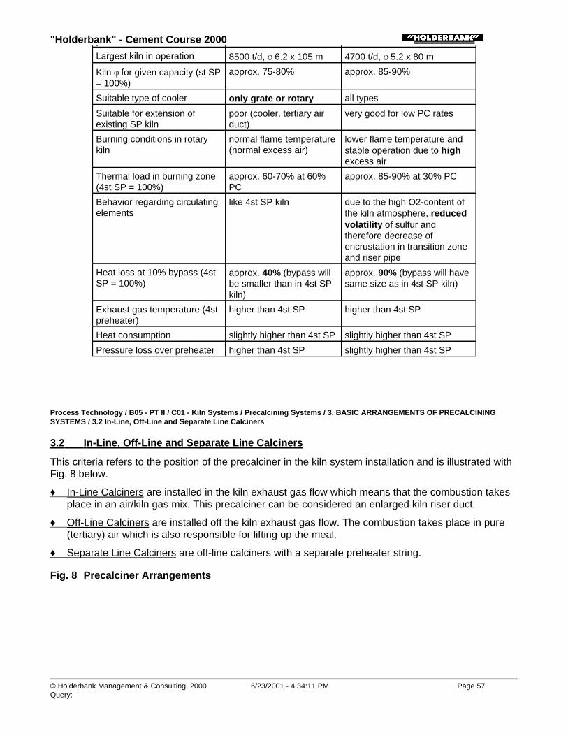
"Holderbank" - Cement Course 2000
© Holderbank Management & Consulting, 2000 6/23/2001 - 4:34:11 PM Page 57Query:
precalciner
Largest kiln in operation 8500 t/d, φ 6.2 x 10⁵ m 4700 t/d, φ 5.2 x 80 m
Kiln φ for given capacity (st SP= 100%)
approx. 75-80% approx. 85-90%
Suitable type of cooler only grate or rotary all types
Suitable for extension ofexisting SP kiln
poor (cooler, tertiary airduct)
very good for low PC rates
Burning conditions in rotarykiln
normal flame temperature(normal excess air)
lower flame temperature andstable operation due to highexcess air
Thermal load in burning zone(4st SP = 100%)
approx. 60-70% at 60%PC
approx. 85-90% at 30% PC
Behavior regarding circulatingelements
like 4st SP kiln due to the high O2-content ofthe kiln atmosphere, reducedvolatility of sulfur andtherefore decrease ofencrustation in transition zoneand riser pipe
Heat loss at 10% bypass (4stSP = 100%)
approx. 40% (bypass willbe smaller than in 4st SPkiln)
approx. 90% (bypass will havesame size as in 4st SP kiln)
Exhaust gas temperature (4stpreheater)
higher than 4st SP higher than 4st SP
Heat consumption slightly higher than 4st SP slightly higher than 4st SP
Pressure loss over preheater higher than 4st SP slightly higher than 4st SP
Process Technology / B05 - PT II / C01 - Kiln Systems / Precalcining Systems / 3. BASIC ARRANGEMENTS OF PRECALCININGSYSTEMS / 3.2 In-Line, Off-Line and Separate Line Calciners
3.2 In-Line, Off-Line and Separate Line Calciners
This criteria refers to the position of the precalciner in the kiln system installation and is illustrated withFig. 8 below.
♦ In-Line Calciners are installed in the kiln exhaust gas flow which means that the combustion takesplace in an air/kiln gas mix. This precalciner can be considered an enlarged kiln riser duct.
♦ Off-Line Calciners are installed off the kiln exhaust gas flow. The combustion takes place in pure(tertiary) air which is also responsible for lifting up the meal.
♦ Separate Line Calciners are off-line calciners with a separate preheater string.
Fig. 8 Precalciner Arrangements

"Holderbank" - Cement Course 2000
© Holderbank Management & Consulting, 2000 6/23/2001 - 4:34:12 PM Page 58Query:
Table 2 Comparison of Calciner Arrangements
In-Line Off-Line Separate Line
PC arrangement Extended riser duct Parallel to riser duct Parallel to riserduct
Combustionatmosphere
Kiln gas and air mix Pure air Pure air
Preheater string 1 to 4 of same size 1 to 4 of same size 2 to 4, 2 differentsizes
Advantages Low NOx version(reducing kiln NOx)
Suitable formodification
Two independentcombustions →Easy combustioncontrol
Excess air used forcombustion
Good combustion Good combustion
Suitable for lumpfuel
Suitable formodifications
Suitable formodifications
Weak points Mixing of air withgas
Higher peaktemperature (NOx!)
Higher peaktemperature(NOx!)
Larger volumerequired
PC drop-out can fillTAD
PC drop-out canfill TAD
Incompletecombustion
Asymmetryregardingcirculatingelements
Height requirement(depending ontype/design)
Requires 2 strings(not feasible for<3000 t/d)
Strings of differentsizes (problem>7000 t/d)
"Holderbank" - Cement Course 2000
© Holderbank Management & Consulting, 2000 6/23/2001 - 4:34:12 PM Page 59Query:
Process Technology / B05 - PT II / C01 - Kiln Systems / Precalcining Systems / 4. FEATURES OF PRECALCINERS
4. FEATURES OF PRECALCINERS
Process Technology / B05 - PT II / C01 - Kiln Systems / Precalcining Systems / 4. FEATURES OF PRECALCINERS / 4.1 Main Benefitsof Precalciner Technology
4.1 Main Benefits of Precalciner Technology
There are many advantages of precalciner technology which made it state of the art today. Some ofthem are listed here:
1) More stable kiln operation due to better kiln control via two separate fuel feed/control points.
2) More stable kiln operation due to controlled meal conditions at kiln inlet.
3) Reduced thermal load of burning zone.
4) Lower brick consumption as a result of 1. and 3.
5) More than double capacities possible with given kiln (10’000 t/d with 6 m x 95 m kiln).
6) Possibility of increasing capacity of existing kilns.
7) Reduced volatilization of circulating elements.
8) Reduction of cycles (S, Cl, Na20, K2O) with smaller bypass rate, i.e. lower losses.
9) Makes short kilns possible with 2 stations, L/D < 12
10) Possibilities of NOx reduction.
11) Lump fuel utilization in some cases.
Process Technology / B05 - PT II / C01 - Kiln Systems / Precalcining Systems / 4. FEATURES OF PRECALCINERS / 4.2 Limitationsand Restrictions
4.2 Limitations and Restrictions
Even though the advantages of precalciner systems are doubtlessly convincing, not all types can beused in all cases. Limitations are:
♦ Additional installation (fuel dosing, calciner, tertiary air duct) as well as the relatively smaller rotarykiln sets a lower economical limit to PC systems for new plants at around 1200 t/d.
♦ Alternative fuels containing hazardous components can only be used in the main firing due to thehigh temperature level there. The potential to use such fuels is then lower for PC kilns.
♦ Higher exhaust gas temperature and higher pressure drop can be a drawback in specific cases.
♦ Separate line calciners for new installations are only feasible if a 2-string arrangement is requiredfor the capacity, i.e. above 3500 t/d.
Fig. 9 Comparison of wet, SP and PC Kilns (average curves)

"Holderbank" - Cement Course 2000
© Holderbank Management & Consulting, 2000 6/23/2001 - 4:34:12 PM Page 60Query:
Process Technology / B05 - PT II / C01 - Kiln Systems / Precalcining Systems / 4. FEATURES OF PRECALCINERS / 4.3 Tertiary AirDamper and Kiln Riser Orifice
4.3 Tertiary Air Damper and Kiln Riser Orifice
Off-line calciners as well as in-line calciners are usually equipped with one kiln ID fan. In order to allowcontrol of the tertiary air/secondary air ratio, there must be a control device in at least one of the twogas paths (kiln resp. tertiary air duct).
For efficient warming up of the preheater, a damper is usually installed in the tertiary air duct to avoidfresh air to bypass the main flame. Very often, this damper is used also, for controlling the tertiary airflow (Fig. 10a). However, experience shows that high temperature and clinker dust require a quiterefined design of this tertiary air damper. In many cases, this damper operates only for a short periodwithout problems.
Another approach is to install the control device in the other path. Some suppliers (e.g. FLS andKawasaki) have developed a kiln riser orifice which is successfully operating in several plants. Thissolution (Fig. 10b) is generally more expensive than the TA damper above, but performs well.
Fig. 10 TA Damper and Kiln Orifice
Process Technology / B05 - PT II / C01 - Kiln Systems / Precalcining Systems / 4. FEATURES OF PRECALCINERS / 4.4 CirculationProblems and Bypass with PC Kilns
4.4 Circulation Problems and Bypass with PC Kilns
Precalciner kiln systems have two major advantages regarding circulation problems.

"Holderbank" - Cement Course 2000
© Holderbank Management & Consulting, 2000 6/23/2001 - 4:34:13 PM Page 61Query:
♦ Reduced volatilization in the rotary kiln because less than 50% of the heat is introduced in theburning zone.
♦ Less than 50% thermal and dust losses in case of a bypass compared to a straight SP kiln.
The volatilization of circulating elements occurs primarily in the rotary kiln. The percentage of thevolatilized elements which can be extracted with a bypass depends on
♦ volatilization rate in the kiln, and
♦ amount of kiln gas extracted via bypass (= bypass rate) which is expressed by the ratio:bypass gas gas at kiln inlet
The highest possible reduction of circulating elements at a given volatilization rate would be if 100% ofthe gases at the kiln inlet could be extracted. this is only possible in the case of a precalciner but notwith a straight preheater kiln. Accordingly are the heat losses approx. 50 to 60% lower at a givenreduction because the concentration of volatilized circulating elements in the gas at the kiln inlet ismuch higher than for a SP kiln.
Fig. 11 Bypass for PC Kilns
Process Technology / B05 - PT II / C01 - Kiln Systems / Precalcining Systems / 5. PRESENT STATE OF PRECALCINERDEVELOPMENT
5. PRESENT STATE OF PRECALCINER DEVELOPMENT
Process Technology / B05 - PT II / C01 - Kiln Systems / Precalcining Systems / 5. PRESENT STATE OF PRECALCINERDEVELOPMENT / 5.1 Calciners from FCB
5.1 Calciners from FCB
FCB have been IHI licensees since the mid seventies for in-line calciners resulting in 8 operatinginstallations and 6 under construction. The highest capacity is 3300 t/d (Tourah, Egypt).
Together with Ciments Français FCB have designed a new type of calciner with low emissions suitablefor low grade fuels called the FCB low NOx PC (Fig. 12).
In combination with a low NOx kiln burner, FCB expect to achieve 150 - 350 ppm NOx at the stack withtheir new calciner. The first industrial prototype is scheduled for 1992.
The FCB calciner looks like a vertical reactor with one three channel burner on the top. Tertiary air isintroduced from the top as well as with the meal on two sides. Flow is vertical from top to bottom. Meal

"Holderbank" - Cement Course 2000
© Holderbank Management & Consulting, 2000 6/23/2001 - 4:34:13 PM Page 62Query:
can be proportioned via three points on two levels. FCB claim to achieve:
♦ Hot spot
♦ Reducing atmosphere zone → NOx reduction
♦ Controlled flame
♦ No separation of coal and meal
Process Technology / B05 - PT II / C01 - Kiln Systems / Precalcining Systems / 5. PRESENT STATE OF PRECALCINERDEVELOPMENT / 5.2 Calciners from FLS - FULLER
5.2 Calciners from FLS - FULLER
The FLS range of calciners will be marketed by both FLS and FULLER.
Three basic air separate calciner systems are available: ILC, SLC-S and SLC (Fig. 13).
All these use a vessel type calciner which provides retention time by means of volume. Experienceswith this system made no conceptual changes necessary.
The only modification to be mentioned is the new tangential tertiary air inlet for the ILC system whichallows larger calciner volume without requiring more height.
Main features of the FLS calciner systems presently available are:
♦ Variable kiln orifice (Fig. 14) for the SLC-S calciner to control the ratio of secondary to tertiary air inplace of the often troublesome damper in the tertiary air duct.
♦ Low NOx version by splitting the tertiary air creating a controlled area of reducing atmosphere inthe lower part of the PC which is horizontally divided in two zones by an orifice.
♦ Variation of the calciner outlet temperature with the SLC-S system without changing the preheatertemperature profile providing a „temperature window“ for NH3 injection.
Process Technology / B05 - PT II / C01 - Kiln Systems / Precalcining Systems / 5. PRESENT STATE OF PRECALCINERDEVELOPMENT / 5.3 PYROCLON Calciners (KHD)
5.3 PYROCLON Calciners (KHD)
The calciner systems by KHD (and Polysius) are based on the 1965 Dottenhausen „goose neck“design, a tube type calciner. As PYROCLON-R, a whole range of versions has been developed (Fig.15).
A low NOx version of the RP version is not available. KHD tackle the problem of CO from incompletecombustion with coal firing by focusing on improved coal dosification.
Incomplete mixture of waste gases from kiln and calciner is often found with tube type calciners. Inorder to achieve a good mixture, an essential prerequisite for low NOx systems using excess fuelzones in the precalciner, the 180°C elbow is substituted by a new reaction chamber, called PYROTOP(Fig. 16).A PYROCLON-R Low NOx with PYROTOP allows:
♦ Complete combustion of the calciner fuel
♦ Temperature controlled zones (NH3 injection)
♦ Improved mixing of gases
♦ Reduction of NOx
"Holderbank" - Cement Course 2000
© Holderbank Management & Consulting, 2000 6/23/2001 - 4:34:13 PM Page 63Query:
Process Technology / B05 - PT II / C01 - Kiln Systems / Precalcining Systems / 5. PRESENT STATE OF PRECALCINERDEVELOPMENT / 5.4 PREPOL® Calciners (Polysius)
5.4 PREPOL® Calciners (Polysius)
Polysius calciners are all of the air separate (AS) h-line-type. It is generally accepted today that thecalcination process takes place within a few seconds making the fuel reactivity the decisive designcriteria for the calciner size.
The „goose neck“-tube type calciner PREPOL by Polysius is presently available in three basicconfigurations (Fig. 17).
Several Polysius calciners have been modified by the company CLE who added an RSP typepre-combustion chamber. The same principle is now incorporated in the PREPOL AS-CC calciner byPolysius.
Polysius started in 1985 to develop their NOx reducing technology called MSC based on experienceavailable from power stations with staged combustion. They have adapted this method to therequirements of the clinker burning process. Trial operation on cement plants have shown 35 - 45%reduction of NOx.
The idea is to create a limited zone of reducing atmosphere near the transition chamber by adding asmall amount of fuel to the rotary kiln exhaust gas via a small burner in the riser duct. For the NOxfrom the calciner fuel, the same principle is applied resulting in a second reducing zone. Such a systemwould have the following fuel inputs:
♦ < 50% main burner
♦ < 10% via primary DeNOx burner
♦ > 30% via precalciner
♦ < 10% via secondary DeNOx burner
Experience on an industrial scale only will prove the capability of this system. One of the difficulties ishow to control the kiln atmosphere without the gas analysis sampled near the kiln inlet.
Process Technology / B05 - PT II / C01 - Kiln Systems / Precalcining Systems / 5. PRESENT STATE OF PRECALCINERDEVELOPMENT / 5.5 Prerov-Calciner
5.5 Prerov-Calciner
The Czek company Prerov have developed a new precalciner (Fig. 18). It consists of a precombustionchamber (KKS) and a reaction chamber (KKN) with a vortex chamber and is comparable to Polysius’PREPOL-AS CC. During 1992, the first installation will be commissioned in Southern Italy.
Process Technology / B05 - PT II / C01 - Kiln Systems / Precalcining Systems / 5. PRESENT STATE OF PRECALCINERDEVELOPMENT / 5.6 Conclusion
5.6 Conclusion
The development of tube type calciners and vessel type calciners has moved them closer to eachother. The tube type calciners have received a swirl pot or a pre-combustion chamber for improvedmixing and fuel burning and the vessel type calciners have become longer.
The calciner without separate air duct also known as „air through“ actually operating only with 10 - 20%of the total fuel never fulfilled the expectations and has virtually disappeared, together with theplanetary cooler.
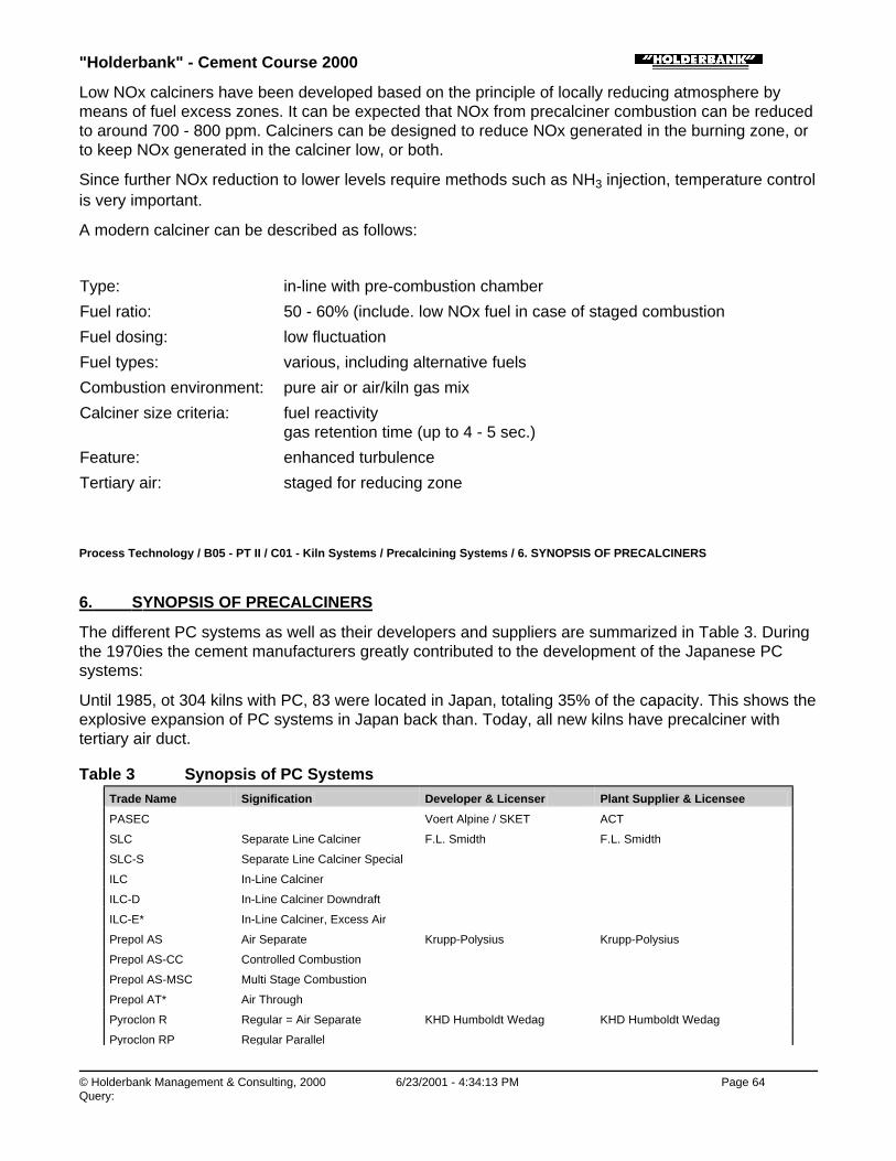
"Holderbank" - Cement Course 2000
© Holderbank Management & Consulting, 2000 6/23/2001 - 4:34:13 PM Page 64Query:
Low NOx calciners have been developed based on the principle of locally reducing atmosphere bymeans of fuel excess zones. It can be expected that NOx from precalciner combustion can be reducedto around 700 - 800 ppm. Calciners can be designed to reduce NOx generated in the burning zone, orto keep NOx generated in the calciner low, or both.
Since further NOx reduction to lower levels require methods such as NH3 injection, temperature controlis very important.
A modern calciner can be described as follows:
Type: in-line with pre-combustion chamber
Fuel ratio: 50 - 60% (include. low NOx fuel in case of staged combustion
Fuel dosing: low fluctuation
Fuel types: various, including alternative fuels
Combustion environment: pure air or air/kiln gas mix
Calciner size criteria: fuel reactivitygas retention time (up to 4 - 5 sec.)
Feature: enhanced turbulence
Tertiary air: staged for reducing zone
Process Technology / B05 - PT II / C01 - Kiln Systems / Precalcining Systems / 6. SYNOPSIS OF PRECALCINERS
6. SYNOPSIS OF PRECALCINERS
The different PC systems as well as their developers and suppliers are summarized in Table 3. Duringthe 1970ies the cement manufacturers greatly contributed to the development of the Japanese PCsystems:
Until 1985, ot 304 kilns with PC, 83 were located in Japan, totaling 35% of the capacity. This shows theexplosive expansion of PC systems in Japan back than. Today, all new kilns have precalciner withtertiary air duct.
Table 3 Synopsis of PC SystemsTrade Name Signification Developer & Licenser Plant Supplier & Licensee
PASEC Voert Alpine / SKET ACT
SLC Separate Line Calciner F.L. Smidth F.L. Smidth
SLC-S Separate Line Calciner Special
ILC In-Line Calciner
ILC-D In-Line Calciner Downdraft
ILC-E* In-Line Calciner, Excess Air
Prepol AS Air Separate Krupp-Polysius Krupp-Polysius
Prepol AS-CC Controlled Combustion
Prepol AS-MSC Multi Stage Combustion
Prepol AT* Air Through
Pyroclon R Regular = Air Separate KHD Humboldt Wedag KHD Humboldt Wedag
Pyroclon RP Regular Parallel
"Holderbank" - Cement Course 2000
© Holderbank Management & Consulting, 2000 6/23/2001 - 4:34:14 PM Page 65Query:
Pyroclon RP Regular Parallel
Pyroclon R Low NOx
Pyroclon R Low Noxwith Pyrotop
Pyroclon S* Special = Air Through
EVS-PC(only fuel - oil)
Echangeur à voie sèche avecprécalcination
Fives-Cail Babcock Fives-Cail Babcock
KKS-KKN n.a. Prero Prerov
SF Suspension Flash Calciner Ishikawajima-Harima HeavyInd.Chichibu Cement
Ishikawajima-Harima Heavy Ind.Fuller Company /Fives-Cail Babcock
NSF New SF
RSP Reinforced SuspensionPreheater
Onoda Cement Onoda Engineering & ConsultingKawasaki Heavy IndustriesAllis-ChalmersCLE-Technip
KSV Kawasaki Spouted Bed andVortex Chamber
Kawasaki Heavy Industries Kawasaki Heavy Industries
NKSV New KSV
MFC Mitsubishi Fluidized Calciner Mitsubishi Mining & Cement Mitsubishi Heavy Industries
GG Reduction Gas Generator Mitsubishi Heavy Industries
DDF Dual Combustion and DenitrationFurnance
Nihon Cement Kobe Steel
CSF (CFF) Chichibu Suspension FlashCalciner
Chichibu Cement Chichibu Cement (own plants)
SCS Sumitomo Cross SuspensionPreheater and Spouted FurnaceProcess
Sumitomo Cement Kawasaki Heavy IndustriesIshikawajima-Harima HeavyIndustries
*Air through: secondary firing systems
Process Technology / B05 - PT II / C01 - Kiln Systems / Precalcining Systems / 7. TEST QUESTIONS
7. TEST QUESTIONS
1) Which is the chemical reaction with the highest heat consumption within the clinker burningprocess? How much does it consume in absolute terms (kJ/kg clinker) and in percent of the totalheat consumption of a modern kiln system?
2) Which are the three basic precalciner arrangements and what are their differences?
3) At what temperature does the calcination take place and how much CO2 is totally dissociated fromthe CaCO3?
4) Which are the benefits of precalciner technology?
5) Which is the most important design criteria for precalciner dimensioning?
6) Explain the term „apparent calcination degree“. How can it be determined and what is itssignificance?
7) How do the effects of a bypass compare in case of a straight preheater kiln and a precalciner kiln?
Fig. 1 Sketch of Dotternhausen Kiln, the first Precalciner (KHD, 1966)

"Holderbank" - Cement Course 2000
© Holderbank Management & Consulting, 2000 6/23/2001 - 4:34:14 PM Page 66Query:
Table 4: Temperatures and Process Steps for Clinker Burning
Temperature [°C] Process Step, Type of Reaction Heat
20 - 100 Evaporation of free H2O Endo
100 - 300 Loss of physically absorbed H2O Endo
400 - 900 Removal of structural water Endo
> 500 Structural changes in silicate minerals Exo
600 - 900 Dissociation of CO2 from CaCO3 Endo
> 800 Formation of intermediate productsBelite, Aluminate and Ferrite
Exo
> 1250 Formation of liquid phase (aluminateand ferrite melt)
Endo
Formation of alite Exo
1300 - 1240 Crystallization of liquid phase into mainlyaluminate and ferrite
Exo
For numerical calculations, an approximate quantity of CO2 from the raw material (dissociated from thecalcites) can be used, regardless of the exact chemical composition.
CO2 from raw mat = 0.28 Nm3/kg cli
Table 5: Energy Balance of Process Steps for Clinker Burning
Endothermic Processes: kJ/kg cli kcal/kg cli
Dehydration of clays 165 40
Decarbonisation of calcite 1990 475
Heat of melting 105 25
Heating of raw materials (0 to 1450°C) 2050 490
Total endothermic 4310 1030

"Holderbank" - Cement Course 2000
© Holderbank Management & Consulting, 2000 6/23/2001 - 4:34:15 PM Page 67Query:
Total endothermic 4310 1030
Exothermic Processes: kJ/kg cli kcal/kg cli
Recrystallization of dehydrated clay 40 10
Heat of formation of clinker minerals 420 100
Crystallization of melt 105 25
Cooling of clinker 1400 335
Cooling of CO2 (ex calcite) 500 120
Cooling and condensation of H2O 85 20
Total exothermic 2550 610
Net Theor. Heat of Clinker Formation: kJ/kg cli kcal/kg cli
Endothermic - exothermic 1760 420
Heat consumption of Kiln System: kJ/kg cli kcal/kg cli
Average 4-stage SP system 3300 790
Modern 6-stage SP system 3000 720
Rel. Heat Requirement of Calcination:
Average 4-stage SP system 60%
Modern 6-stage SP system 66%
Fig. 12 FCB Low-NOx Precalciner
Fig. 13 FLS

"Holderbank" - Cement Course 2000
© Holderbank Management & Consulting, 2000 6/23/2001 - 4:34:15 PM Page 68Query:
Fig. 14 FLS Adjustable Kiln Orifice
Fig. 15 Pyroclon
Fig. 16 Pyrotop
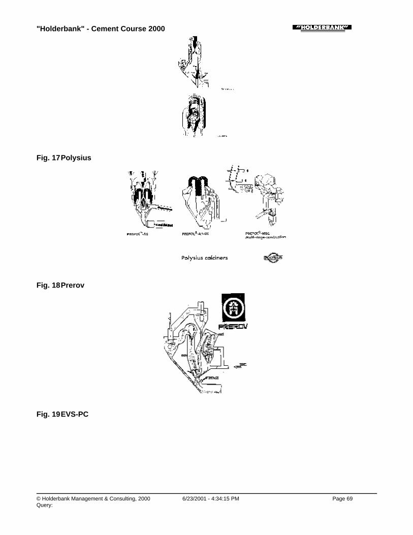
"Holderbank" - Cement Course 2000
© Holderbank Management & Consulting, 2000 6/23/2001 - 4:34:15 PM Page 69Query:
Fig. 17 Polysius
Fig. 18 Prerov
Fig. 19 EVS-PC

"Holderbank" - Cement Course 2000
© Holderbank Management & Consulting, 2000 6/23/2001 - 4:34:15 PM Page 70Query:
Features of EVS-PC PC system
Supplier: Fives-Cail Babcock
Fig. 20 SF / NSF
Fig. 21 RSP
Features of RSP PC system
Suppliers: Onoda Engineering & Consulting Kawasaki Heavy Industries Allis Chalmers Creusot - Loire Entreprises

"Holderbank" - Cement Course 2000
© Holderbank Management & Consulting, 2000 6/23/2001 - 4:34:16 PM Page 71Query:
Fig. 22 KSV / NKSV
Features of KSV/NKSV PC system
Supplier: Kawasaki Heavy Industries
Fig. 23 MFC
Fig. 24 GG
Features of GG PC system
Supplier: Mitsubishi Heavy Industries
System abandoned
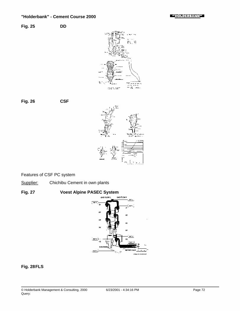
"Holderbank" - Cement Course 2000
© Holderbank Management & Consulting, 2000 6/23/2001 - 4:34:16 PM Page 72Query:
Fig. 25 DD
Fig. 26 CSF
Features of CSF PC system
Supplier: Chichibu Cement in own plants
Fig. 27 Voest Alpine PASEC System
Fig. 28 FLS

"Holderbank" - Cement Course 2000
© Holderbank Management & Consulting, 2000 6/23/2001 - 4:34:16 PM Page 73Query:

"Holderbank" - Cement Course 2000
© Holderbank Management & Consulting, 2000 6/23/2001 - 4:34:17 PM Page 74Query:
Process Technology / B05 - PT II / C01 - Kiln Systems / Clinker Coolers
Clinker CoolersU. Gasser / D. BrasselPT 97/14232/E (Revision 1, February 1999)
1. INTRODUCTION
2. GENERAL CONSIDERATIONS
2.1 Heat Flow in a Kiln System
2.2 Definitions
2.3 Calculations
3. GRATE COOLERS
3.1 The Reciprocating Grate Cooler
3.1.1 Principle
3.1.2 History
3.1.3 Conventional Grate Coolers (1980’s)
3.1.4 Typical Grate Cooler Problems
3.1.5 Modern Grate Coolers (1990’s)
3.1.6 Design Highlights of Modern Grate Coolers
3.1.7 Clinker Crushers
3.1.8 Cooler control
3.1.9 Cooler Dedusting
3.1.10 Developments
3.2 The Cross Bar Cooler
3.2.1 Principle
3.2.2 Main features
3.2.3 Strengths and Weaknesses
3.3 The Travelling Grate Cooler
3.3.1 Principle
3.3.2 Strengths and Weaknesses
4. ROTATING COOLERS
4.1 The Rotary Cooler or Tube Cooler
4.1.1 Principle
4.1.2 Design Features
4.1.3 Cooling performance

"Holderbank" - Cement Course 2000
© Holderbank Management & Consulting, 2000 6/23/2001 - 4:34:17 PM Page 75Query:
4.1.4 Strengths / Weaknesses
4.2 The Planetary Cooler
4.2.1 Principle
4.2.2 Historical
4.2.3 Design features
4.2.4 Internal heat transfer equipment (see Fig. 26)
5. VERTICAL COOLERS
5.1 The Gravity Cooler (G - Cooler)
5.2 The Shaft Cooler
SUMMARY
Clinker coolers have two tasks to fulfil:
♦ Recuperate as much heat as possible from the hot clinker by heating up the air used forcombustion
♦ Cool the clinker from 1400°C to temperatures adequate for the subsequent process equipment,normally to 100 - 200°C.
There are mainly two different types of clinker coolers in operation with the following features:
Grate coolers
♦ Crossflow heat exchange through horizontal clinker bed with cold air from below.
♦ Cooling airflow exceeding combustion air requirement allows low clinker temperatures, butnecessitates excess (waste) air dedusting.
♦ Modern cooler technology with sophisticated plates and forced aeration systems allow combustionair temperatures exceeding 1000°C.
♦ Trend to wider and fewer grates, less cooling air and fixed inlets
♦ Largest units: 10’000 t/d
♦ Travelling grate (Recupol): last unit built around 1980
Rotating coolers
♦ Rotary tube coolers with separate drive or planetary cooler attached to kiln shell
♦ Quasi counter-current flow heat exchange
♦ Cooling air determined by combustion air, no waste air
♦ Heat exchange (recuperation) determined by condition of internal heat transfer equipment
♦ Limited unit size, up to 3000 t/d
♦ Planetary cooler not suitable for precalciner technology
♦ Practically no new installation built anymore
Process Technology / B05 - PT II / C01 - Kiln Systems / Clinker Coolers / 1. INTRODUCTION

"Holderbank" - Cement Course 2000
© Holderbank Management & Consulting, 2000 6/23/2001 - 4:34:17 PM Page 76Query:
1. INTRODUCTION
The clinker cooler is a vital part of the kiln system and has a decisive influence on the performance ofthe plant. Three key indicators characterize a good cooler:
♦ Maximum heat recuperation
♦ Minimum cooling air flow
♦ Unrestricted availability
There have been periodic changes in trends during the past decades. Grate coolers were firstintroduced by Fuller Company (USA) around 1930. While its design was continuously being optimized,the grate cooler became the predominant type in the 1950's. In the late 1960's, the planetary coolergained popularity which reached its peak in the 1970's, mainly due to its simplicity. Larger unitcapacities with precalciner technology made the grate cooler the preferred solution again. A wave ofgrate cooler reengineering starting in the mid 1980's has generated a much improved grate coolertechnology as well as a new situation on the suppliers' side. New problems were experienced and havebeen or are being solved.
Since cement plants have life cycles of 40 years and more, numerous units of each cooler type,planetary, rotary or grate cooler of old or new designs, will remain in operation for many more years.
Process Technology / B05 - PT II / C01 - Kiln Systems / Clinker Coolers / 2. GENERAL CONSIDERATIONS
2. GENERAL CONSIDERATIONS
The clinker cooler has the following tasks to fulfil:
♦ Process internal heat recuperation by heat transfer from clinker to combustion air
♦ Reduce clinker temperature to facilitate clinker handling and storage
♦ Provide maximum cooling velocity to avoid unfavorable clinker phases and crystal size
Process Technology / B05 - PT II / C01 - Kiln Systems / Clinker Coolers / 2. GENERAL CONSIDERATIONS / 2.1 Heat Flow in a KilnSystem
2.1 Heat Flow in a Kiln System
The importance of the cooler as a heat recuperator can be well demonstrated with a heat flow (Sanki)diagram.
Figure 1 Clinker cooler and kiln system
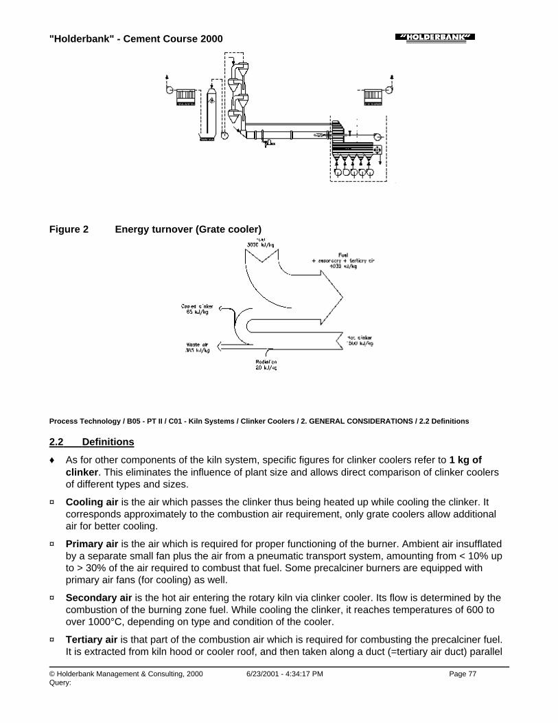
"Holderbank" - Cement Course 2000
© Holderbank Management & Consulting, 2000 6/23/2001 - 4:34:17 PM Page 77Query:
Figure 2 Energy turnover (Grate cooler)
Process Technology / B05 - PT II / C01 - Kiln Systems / Clinker Coolers / 2. GENERAL CONSIDERATIONS / 2.2 Definitions
2.2 Definitions
♦ As for other components of the kiln system, specific figures for clinker coolers refer to 1 kg ofclinker. This eliminates the influence of plant size and allows direct comparison of clinker coolersof different types and sizes.
♦ Cooling air is the air which passes the clinker thus being heated up while cooling the clinker. Itcorresponds approximately to the combustion air requirement, only grate coolers allow additionalair for better cooling.
♦ Primary air is the air which is required for proper functioning of the burner. Ambient air insufflatedby a separate small fan plus the air from a pneumatic transport system, amounting from < 10% upto > 30% of the air required to combust that fuel. Some precalciner burners are equipped withprimary air fans (for cooling) as well.
♦ Secondary air is the hot air entering the rotary kiln via clinker cooler. Its flow is determined by thecombustion of the burning zone fuel. While cooling the clinker, it reaches temperatures of 600 toover 1000°C, depending on type and condition of the cooler.
♦ Tertiary air is that part of the combustion air which is required for combusting the precalciner fuel.It is extracted from kiln hood or cooler roof, and then taken along a duct (=tertiary air duct) parallel
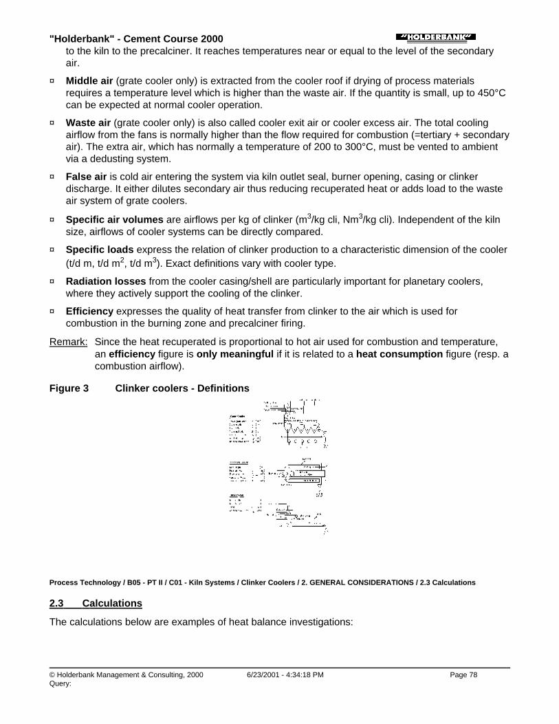
"Holderbank" - Cement Course 2000
© Holderbank Management & Consulting, 2000 6/23/2001 - 4:34:18 PM Page 78Query:
to the kiln to the precalciner. It reaches temperatures near or equal to the level of the secondaryair.
♦ Middle air (grate cooler only) is extracted from the cooler roof if drying of process materialsrequires a temperature level which is higher than the waste air. If the quantity is small, up to 450°Ccan be expected at normal cooler operation.
♦ Waste air (grate cooler only) is also called cooler exit air or cooler excess air. The total coolingairflow from the fans is normally higher than the flow required for combustion (=tertiary + secondaryair). The extra air, which has normally a temperature of 200 to 300°C, must be vented to ambientvia a dedusting system.
♦ False air is cold air entering the system via kiln outlet seal, burner opening, casing or clinkerdischarge. It either dilutes secondary air thus reducing recuperated heat or adds load to the wasteair system of grate coolers.
♦ Specific air volumes are airflows per kg of clinker (m3/kg cli, Nm3/kg cli). Independent of the kilnsize, airflows of cooler systems can be directly compared.
♦ Specific loads express the relation of clinker production to a characteristic dimension of the cooler(t/d m, t/d m2, t/d m3). Exact definitions vary with cooler type.
♦ Radiation losses from the cooler casing/shell are particularly important for planetary coolers,where they actively support the cooling of the clinker.
♦ Efficiency expresses the quality of heat transfer from clinker to the air which is used forcombustion in the burning zone and precalciner firing.
Remark: Since the heat recuperated is proportional to hot air used for combustion and temperature,an efficiency figure is only meaningful if it is related to a heat consumption figure (resp. acombustion airflow).
Figure 3 Clinker coolers - Definitions
Process Technology / B05 - PT II / C01 - Kiln Systems / Clinker Coolers / 2. GENERAL CONSIDERATIONS / 2.3 Calculations
2.3 Calculations
The calculations below are examples of heat balance investigations:
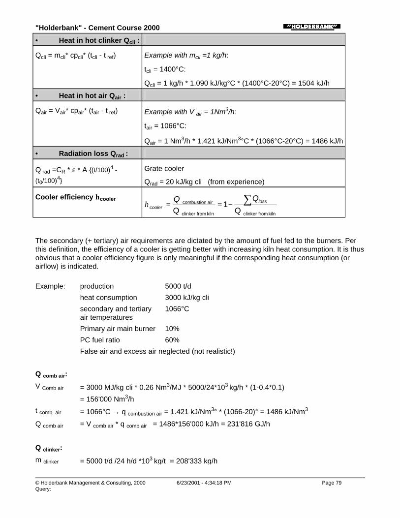
"Holderbank" - Cement Course 2000
© Holderbank Management & Consulting, 2000 6/23/2001 - 4:34:18 PM Page 79Query:
• Heat in hot clinker Qcli :
Qcli = mcli* cpcli* (tcli - t ref) Example with mcli =1 kg/h:
tcli = 1400°C:
Qcli = 1 kg/h * 1.090 kJ/kg°C * (1400°C-20°C) = 1504 kJ/h
• Heat in hot air Qair :
Qair = Vair* cpair* (tair - t ref) Example with V air = 1Nm3/h:
tair = 1066°C:
Qair = 1 Nm3/h * 1.421 kJ/Nm3°C * (1066°C-20°C) = 1486 kJ/h
• Radiation loss Qrad :
Q rad =CR * ε * A {(t/100)4 -
(t0/100)4}
Grate cooler
Qrad = 20 kJ/kg cli (from experience)
Cooler efficiency ηcooler
kiln from clinkerkiln from clinker
air combustion
Q1
Q ∑−== loss
cooler
QQη
The secondary (+ tertiary) air requirements are dictated by the amount of fuel fed to the burners. Perthis definition, the efficiency of a cooler is getting better with increasing kiln heat consumption. It is thusobvious that a cooler efficiency figure is only meaningful if the corresponding heat consumption (orairflow) is indicated.
Example: production 5000 t/d
heat consumption 3000 kJ/kg cli
secondary and tertiaryair temperatures
1066°C
Primary air main burner 10%
PC fuel ratio 60%
False air and excess air neglected (not realistic!)
Q comb air:
V Comb air = 3000 MJ/kg cli * 0.26 Nm3/MJ * 5000/24*103 kg/h * (1-0.4*0.1)
= 156'000 Nm3/h
t comb air = 1066°C → q combustion air = 1.421 kJ/Nm3° * (1066-20)° = 1486 kJ/Nm3
Q comb air = V comb air * q comb air = 1486*156'000 kJ/h = 231'816 GJ/h
Q clinker:
m clinker = 5000 t/d /24 h/d *103 kg/t = 208'333 kg/h
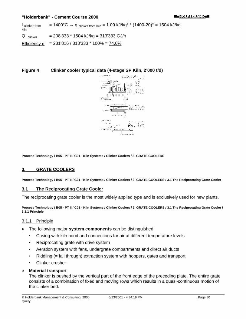
"Holderbank" - Cement Course 2000
© Holderbank Management & Consulting, 2000 6/23/2001 - 4:34:19 PM Page 80Query:
m clinker = 5000 t/d /24 h/d *103 kg/t = 208'333 kg/h
t clinker fromkiln
= 1400°C → q clinker from kiln = 1.09 kJ/kg° * (1400-20)° = 1504 kJ/kg
Q clinker = 208'333 * 1504 kJ/kg = 313'333 GJ/h
Efficiency η = 231'816 / 313'333 * 100% = 74.0%
Figure 4 Clinker cooler typical data (4-stage SP Kiln, 2’000 t/d)
Process Technology / B05 - PT II / C01 - Kiln Systems / Clinker Coolers / 3. GRATE COOLERS
3. GRATE COOLERS
Process Technology / B05 - PT II / C01 - Kiln Systems / Clinker Coolers / 3. GRATE COOLERS / 3.1 The Reciprocating Grate Cooler
3.1 The Reciprocating Grate Cooler
The reciprocating grate cooler is the most widely applied type and is exclusively used for new plants.
Process Technology / B05 - PT II / C01 - Kiln Systems / Clinker Coolers / 3. GRATE COOLERS / 3.1 The Reciprocating Grate Cooler /3.1.1 Principle
3.1.1 Principle
♦ The following major system components can be distinguished:
• Casing with kiln hood and connections for air at different temperature levels
• Reciprocating grate with drive system
• Aeration system with fans, undergrate compartments and direct air ducts
• Riddling (= fall through) extraction system with hoppers, gates and transport
• Clinker crusher
♦ Material transportThe clinker is pushed by the vertical part of the front edge of the preceding plate. The entire grateconsists of a combination of fixed and moving rows which results in a quasi-continuous motion ofthe clinker bed.

"Holderbank" - Cement Course 2000
© Holderbank Management & Consulting, 2000 6/23/2001 - 4:34:19 PM Page 81Query:
♦ Heat exchangeHeat exchange from clinker to air is according to the cross current principle. The cooling airpenetrates the clinker bed which is laying on the grate from underneath and leaves it at thesurface. While passing through the hot clinker, the air is accumulating heat which is transferredfrom the clinker.
♦ Cooling airNormally, ambient air is blown to underneath of the grate plates loaded with clinker by a number ofcooling air fans. Delivery pressure must be sufficient to penetrate the clinker bed and tocompensate for the expansion (increase of actual volume) of the air from heating it upUnder ideal conditions, the required cooling air depends directly from the desired clinkertemperature. One part of the cooling air is used for combustion in the kiln, the rest is cleaned andvented to ambient, unless it is further used, e.g. for drying.
♦ Cooling curveA simplified mathematical model for clinker cooling in a conventional, optimized grate cooler givesthe relation between cooling air quantity and clinker temperature as follows:
[ ])77.0/(exp
TTT T
ambin cli
ambcliairV−=
−−
with T cli
in
= clinker temperature at cooler inlet °C
T amb = ambient temperature °C
V air = cooling air quantity Nm3/kg cli
The above approximation (curve Fig. 17: Tcli = 1400°C) has been found to give satisfactory results forconventional grate coolers from various suppliers.
Figure 5 Reciprocating Grate Cooler: Design Features
Process Technology / B05 - PT II / C01 - Kiln Systems / Clinker Coolers / 3. GRATE COOLERS / 3.1 The Reciprocating Grate Cooler /3.1.2 History
3.1.2 History

"Holderbank" - Cement Course 2000
© Holderbank Management & Consulting, 2000 6/23/2001 - 4:34:19 PM Page 82Query:
It was the Fuller Company (USA) who introduced the first reciprocating grate cooler in the late 1930'swith a grate slope of 15°.
Fluidized material running down the grate leads to 10° grate inclination. The 10° cooler waspredominantly used until the mid 1950's. Problems were encountered with those 10° coolers when theclinker was fine and started to fluidize. As an attempt to solve this problem, wedge grate plates wereused. Another drawback of those 10° coolers was the building height required for larger units.
In the mid 1950's, the first horizontal grate coolers were introduced. They were initially just 10° gratesinstalled horizontally with accordingly reduced conveying capacity. Some of these coolers wereseverely damaged by overheating, due to fluidization and accumulation of hot fine clinker at the feedend.
This drawback of the horizontal cooler lead to the development of the so-called combi cooler. Is hasone (or formerly two) inclined grates with normally 3° slope, followed by one or two horizontal grates.Not all suppliers followed the same philosophies, so all three concepts (all horizontal, combi and allinclined) can be found all over the world.
The planetary cooler boom period in the 1970's came to an end, when large production capacities werein demand. Precalciner technology required grate coolers which eventually needed to be reengineeredagain. Problems related to the clinker distribution, growing awareness of heat and power consumptionas well as the demand for higher availability forced the suppliers to introduce new solutions. Initiated bythe new company IKN, the grate cooler technology underwent significant changes since the mid1980's. Modern grate plates, forced (direct) aeration and better gap design were introduced by allcooler makers helping to reduce cooling airflow and cooler size.
The new approach lead to better recuperation in most cases. However, serious wear problems withthe new systems forced most of the companies to modify their solutions once again. Today, in the mid1990's, we are still gaining experience with latest designs.
The ultimate solution would be the waste air free grate cooler with unlimited flexibility and availability.However, right now the cement industry would be happy with smooth operation, high recuperation, lowcooling air and no cooler related kiln stops.
Figure 6 Various configurations of reciprocating grate coolers
Process Technology / B05 - PT II / C01 - Kiln Systems / Clinker Coolers / 3. GRATE COOLERS / 3.1 The Reciprocating Grate Cooler /3.1.3 Conventional Grate Coolers (1980’s)
3.1.3 Conventional Grate Coolers (1980’s)

"Holderbank" - Cement Course 2000
© Holderbank Management & Consulting, 2000 6/23/2001 - 4:34:20 PM Page 83Query:
Process Technology / B05 - PT II / C01 - Kiln Systems / Clinker Coolers / 3. GRATE COOLERS / 3.1 The Reciprocating Grate Cooler /3.1.3 Conventional Grate Coolers (1980’s) / 3.1.3.1 Typical Design Features
3.1.3.1 Typical Design Features
♦ Grate plates with round holes
♦ Two to three grates, depending on size
♦ Grate slope 0° or 3° or both, depending on supplier
♦ Mechanical excenter drives for reciprocating grate
♦ Chamber aeration
♦ Fan pressure 45 mbar (first) to 25 mbar (last)
♦ Smaller compartments at inlet, larger towards outlet
♦ Clinker riddling extraction with hoppers, gates and dragchain (some earlier designs: internal dragchain without hoppers)
♦ Hammer crusher at cooler discharge
World’s largest kilns (10'000 t/d in Thailand) are equipped with conventional grate coolers from CPAGwith 4 grates.
Process Technology / B05 - PT II / C01 - Kiln Systems / Clinker Coolers / 3. GRATE COOLERS / 3.1 The Reciprocating Grate Cooler /3.1.3 Conventional Grate Coolers (1980’s) / 3.1.3.2 Strengths and Weaknesses of Conventional Grate Coolers
3.1.3.2 Strengths and Weaknesses of Conventional Grate Coolers
Strenghts Weaknesses
• Lower clinker end temperature due tohigher amount of cooling air
• Possibility of adjusting cooling air andgrate speed provides higher flexibility
• Optimization possibilities duringoperation
• Waste air handling system(dedusting, fan) required
• More complex cooler requires highercapital investment
• Higher power consumption thanplanetary or tube cooler
• Uneven clinker discharge /segregation leads to severalproblems
• Red river
• Snowmen
• Air breakthrough (bubbling, geyser)
• Reduced plate life
• Excessive clinker fall throughbetween gaps

"Holderbank" - Cement Course 2000
© Holderbank Management & Consulting, 2000 6/23/2001 - 4:34:20 PM Page 84Query:
Causes and mechanism of those problems are further explained in the next paragraph.
Figure 7 Conventional grate coolers: Design features
Process Technology / B05 - PT II / C01 - Kiln Systems / Clinker Coolers / 3. GRATE COOLERS / 3.1 The Reciprocating Grate Cooler /3.1.4 Typical Grate Cooler Problems
3.1.4 Typical Grate Cooler Problems
Most grate coolers show a tendency to one or more of the system inherent problems, and in manycases there is no real cure. Investigations of the causes lead to the development of the modern coolertechnology.
♦ Segregation:Due to its physical properties, the clinker is lifted by the kiln rotation before it is discharged into thecooler. Installation of the grate axis offset from the cooler axis should compensate for this effect.However, since discharge behavior of finer and coarser clinker particles differ from each other, theclinker fractions are not evenly distributed across the grate. Fines are discharged later and are thusfound predominantly on the rising side of the kiln shell (Fig. 8a).
♦ Thin clinker bed in recuperation zone:With a conventional grate cooler with chamber aeration, the clinker bed thickness is limited directlyby the installed cooling fan pressure and indirectly by the quality of compartment seals anddistribution of the clinker across the width. In order to avoid overheated plates, the operator will setthe bed not higher than allowed to guarantee airflow through the plate carrying the clinker with thehighest bed resistance.Thin bed operation leads to unfavorably high air to clinker ratio and poor heat exchange on thesides with consequently low recuperation efficiency.
♦ Red river:The infamous red river is one of the most feared problems with grate coolers.Due to segregation, fine clinker has always its preferred side (see above).Different bed resistance on either side and only one air chamber across the entire width oftencause fluidization of the fine clinker laying on top. This fluidized clinker does no longer follow thespeed of the grate, but shoots much faster towards the cooler discharge end. Because theresidence time of that fine clinker is much reduced, it does not follow the general cooling curve and

"Holderbank" - Cement Course 2000
© Holderbank Management & Consulting, 2000 6/23/2001 - 4:34:21 PM Page 85Query:
forms a red hot layer on top of the regularly cooled, already black clinker. Hence the term "redriver". It is not the missed heat recuperation, but the red hot material being in touch with cooler walls,plates and side seals in the colder area where such temperatures should normally not occur.Premature destruction of those pieces results in poor availability, high maintenance and ultimatelyin loss of production and sales revenues.
♦ Snowman:The sticky consistence of the hot clinker leaving the kiln combined with the compaction at the droppoint often leads to formation of solid clinker mountains on the grate. Not permeable for cooling air,they grow larger and disturb the flow pattern of the clinker in this anyway critical inlet area.
♦ Air breaking through:Due to the different resistance of the clinker bed and the fear of overheated plates, too much air isput on the first grate compared to the clinker bed. The result is air shooting through the bed, hardlytaking any heat and thus not contributing to the heat exchange.In addition to that, the clinker is mixed which can be seen by the bubbling action, and the layeredclinker bed (colder clinker below, hotter on top) is destroyed thus disturbing the cross flow heatexchange pattern. The results are low recuperation and too much heat going to the aftercooling zone.
♦
Figure 8a: Segregation at cooler inlet
Figure 8b: Clinker bed depth effect oncooling
Figure 8c Red River Figure 8d Snowman

"Holderbank" - Cement Course 2000
© Holderbank Management & Consulting, 2000 6/23/2001 - 4:34:21 PM Page 86Query:
Process Technology / B05 - PT II / C01 - Kiln Systems / Clinker Coolers / 3. GRATE COOLERS / 3.1 The Reciprocating Grate Cooler /3.1.5 Modern Grate Coolers (1990’s)
3.1.5 Modern Grate Coolers (1990’s)
Process Technology / B05 - PT II / C01 - Kiln Systems / Clinker Coolers / 3. GRATE COOLERS / 3.1 The Reciprocating Grate Cooler /3.1.5 Modern Grate Coolers (1990’s) / 3.1.5.1 Design Features
3.1.5.1 Design Features
The successful clinker cooler has:
1) À Correct allocation of cooling air to clinker
Á Sustainable gap widths in the entire cooler
All new or redesigned clinker coolers are aiming at the above two goals:
♦ Modern grate plates, designed to cope with high temperature differences
♦ Inclined inlet section without moving rows
♦ Pattern of zones for individually adjustable aeration in recuperation zone
♦ Modern plates for a tight grate in the after cooling zone
♦ New, improved side seal plate design for tight gaps and low wear
♦ Careful undergrate compartment sealing
♦ Adequate seal air system with correct control
♦ Wider and shorter coolers; lower number of grates
♦ Improved and wear protected moving grate support and guidance
♦ Hydraulic grate drive with optimized control system
♦ Cooling air fans with inlet vane control and inlet nozzle for measuring flow
♦ Roller crusher
Process Technology / B05 - PT II / C01 - Kiln Systems / Clinker Coolers / 3. GRATE COOLERS / 3.1 The Reciprocating Grate Cooler /3.1.5 Modern Grate Coolers (1990’s) / 3.1.5.2 Strengths and Weaknesses of Modern Grate Coolers
3.1.5.2 Strengths and Weaknesses of Modern Grate Coolers
Strenghts Weaknesses
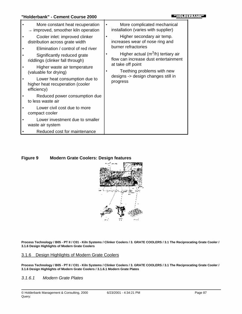
"Holderbank" - Cement Course 2000
© Holderbank Management & Consulting, 2000 6/23/2001 - 4:34:21 PM Page 87Query:
Strenghts Weaknesses
• More constant heat recuperation→ improved, smoother kiln operation
• Cooler inlet: improved clinkerdistribution across grate width
• Elimination / control of red river
• Significantly reduced grateriddlings (clinker fall through)
• Higher waste air temperature(valuable for drying)
• Lower heat consumption due tohigher heat recuperation (coolerefficiency)
• Reduced power consumption dueto less waste air
• Lower civil cost due to morecompact cooler
• Lower investment due to smallerwaste air system
• Reduced cost for maintenance
• More complicated mechanicalinstallation (varies with supplier)
• Higher secondary air temp.increases wear of nose ring andburner refractories
• Higher actual (m3/h) tertiary airflow can increase dust entertainmentat take off point
• Teething problems with newdesigns -> design changes still inprogress
Figure 9 Modern Grate Coolers: Design features
Process Technology / B05 - PT II / C01 - Kiln Systems / Clinker Coolers / 3. GRATE COOLERS / 3.1 The Reciprocating Grate Cooler /3.1.6 Design Highlights of Modern Grate Coolers
3.1.6 Design Highlights of Modern Grate Coolers
Process Technology / B05 - PT II / C01 - Kiln Systems / Clinker Coolers / 3. GRATE COOLERS / 3.1 The Reciprocating Grate Cooler /3.1.6 Design Highlights of Modern Grate Coolers / 3.1.6.1 Modern Grate Plates
3.1.6.1 Modern Grate Plates
"Holderbank" - Cement Course 2000
© Holderbank Management & Consulting, 2000 6/23/2001 - 4:34:22 PM Page 88Query:
In the mid 1980's, the first modern grate plates were installed in grate coolers by IKN and CPAG. Theywere designed for the following targets:
♦ Allow for lower air/clinker ratio in the recuperation zone for higher recuperation
♦ Improve clinker distribution across the grate width
♦ Assure that all grate plates are always sufficiently cooled by air
The above targets were reached using the following ideas:
• Higher built-in pressure dropSimilar to the effect of thick bed operation, a higher pressure drop across the plate reduces therelative influence of variations in permeability of the clinker bed.
• No more fine clinker falling throughFine clinker falling through means loss of heat and thermal stress on the drag chain. For forcedaeration (below) it is mandatory that no material can fall in the air ducts where it would cut offthe air supply.
• Forced (direct) aeration via air ductsIn order to ensure that all plates get enough air, to allow individual allocation of air to differentareas and to avoid that air escapes through gaps, groups of plates are supplied with air directlyvia a special duct system
• Tight gaps between plates and plates/casingNot only through the grate surface, but also through gaps between plates within the same rowas well as from one row to the next, fine clinker can fall through. Those gaps have to be sealedas well, e.g. by interlinked steps in the plate sides (Fuller, Polysius) or by bolting them togetheras packages (IKN).
The modern grate plates are the basis of modern cooler technology. Problems experienced with thefirst generation of modern grate plates lead to several detail modifications:
♦ Cracks in corners of air outlet openings→ Solution: modified shape
♦ Plastic deformation caused premature failure with many designs→ Solution: thermally flexible plates built from two or more pieces
♦ Preferred plate internal airflow left plates locally uncooled → Solution: plate internal guide vanes, optimized air channelling
♦
♦ Modern grate cooler, as the IKN Pendulum Cooler, use also Pneumatic Hopper Drains (PHD) towithdraw the fine clinker fall through.
Figure 10 Modern grate plates

"Holderbank" - Cement Course 2000
© Holderbank Management & Consulting, 2000 6/23/2001 - 4:34:22 PM Page 89Query:
Process Technology / B05 - PT II / C01 - Kiln Systems / Clinker Coolers / 3. GRATE COOLERS / 3.1 The Reciprocating Grate Cooler /3.1.6 Design Highlights of Modern Grate Coolers / 3.1.6.2 Air Ducts
3.1.6.2 Air Ducts
The concept of forced aeration, i.e. the idea to bring the air directly to the grate plates requires aflexible air connection between the (stationary) fan and the moving rows.
Initially, the most obvious and simple approach was chosen: flexible hoses or bellows. IKN, CPAG,Polysius and Fuller used this solution at the beginning.
However, experience showed that those hoses were sensitive to design (geometry), installation andmaterial qualities. While many coolers operated without any problem, others showed frequent ruptureof those hoses, very often causing severe plate damage and consequently kiln downtime.
Meanwhile, all suppliers developed new solutions. Only KHD avoided these problems by usingtelescopic ducts from the beginning.
The individual suppliers are now using the following standard solutions:
♦ Telescopic air connector (BMH-CPAG, KHD)
♦ Ball and socket type air connector (FLS, Fuller)
♦ Gate type air connector (Polysius)
♦ Open air beam (IKN)
Figure 11 Forced (direct) aeration to moving rows: Flexible ducts

"Holderbank" - Cement Course 2000
© Holderbank Management & Consulting, 2000 6/23/2001 - 4:34:22 PM Page 90Query:
Process Technology / B05 - PT II / C01 - Kiln Systems / Clinker Coolers / 3. GRATE COOLERS / 3.1 The Reciprocating Grate Cooler /3.1.6 Design Highlights of Modern Grate Coolers / 3.1.6.3 Aeration Concept
3.1.6.3 Aeration Concept
It was soon recognized that only a few (6 to 8) rows of direct and individual aeration are not sufficientto improve clinker distribution or to eliminate/control red river formation. The number of rows with directaeration was gradually increased and soon the suppliers started to equip the entire recuperation zoneor even the entire cooler with direct aeration. Indeed, this improved the control possibilities, but createdthe following new drawbacks:
♦ Complicated and expensive equipment
♦ More parameters to control
♦ Difficult access underneath grate
♦ High number of potential problem areas (flexible hoses!)
Ways had to be found to reduce the number of air ducts to the individually aerated cooler zones. Thereare two ways to achieve this:
♦ Reduce number of individually aerated zones
♦ Modify the air duct system
Today, the following different solutions with varying degrees of experience are presently available fromthe suppliers:
♦ No moving rows requiring flexible air connectors in inlet section
♦ Longitudinal structural beams designed as air ducts
♦ Short air ducts from one moving row to the next (“Air bridge“)
♦ Direct aeration for fixed rows only (“hybrid aeration“)
♦ Full chamber aeration with modern grate plates
Figure 12 Aeration patterns
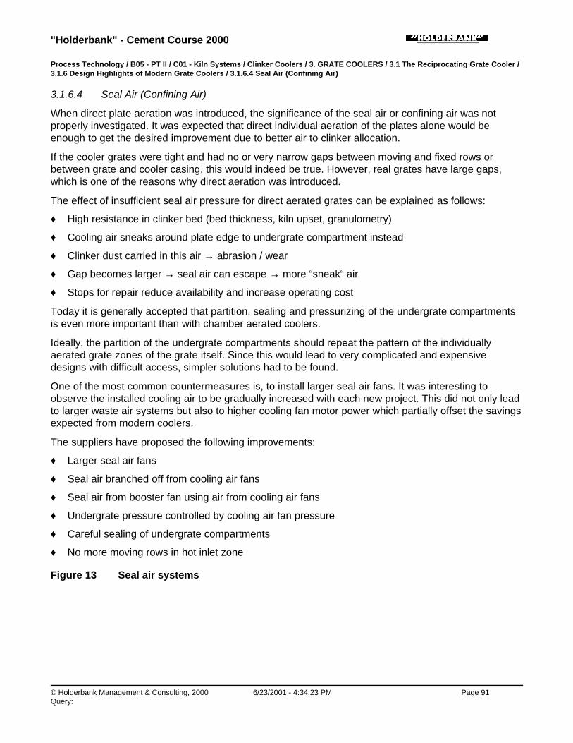
"Holderbank" - Cement Course 2000
© Holderbank Management & Consulting, 2000 6/23/2001 - 4:34:23 PM Page 91Query:
Process Technology / B05 - PT II / C01 - Kiln Systems / Clinker Coolers / 3. GRATE COOLERS / 3.1 The Reciprocating Grate Cooler /3.1.6 Design Highlights of Modern Grate Coolers / 3.1.6.4 Seal Air (Confining Air)
3.1.6.4 Seal Air (Confining Air)
When direct plate aeration was introduced, the significance of the seal air or confining air was notproperly investigated. It was expected that direct individual aeration of the plates alone would beenough to get the desired improvement due to better air to clinker allocation.
If the cooler grates were tight and had no or very narrow gaps between moving and fixed rows orbetween grate and cooler casing, this would indeed be true. However, real grates have large gaps,which is one of the reasons why direct aeration was introduced.
The effect of insufficient seal air pressure for direct aerated grates can be explained as follows:
♦ High resistance in clinker bed (bed thickness, kiln upset, granulometry)
♦ Cooling air sneaks around plate edge to undergrate compartment instead
♦ Clinker dust carried in this air → abrasion / wear
♦ Gap becomes larger → seal air can escape → more “sneak“ air
♦ Stops for repair reduce availability and increase operating cost
Today it is generally accepted that partition, sealing and pressurizing of the undergrate compartmentsis even more important than with chamber aerated coolers.
Ideally, the partition of the undergrate compartments should repeat the pattern of the individuallyaerated grate zones of the grate itself. Since this would lead to very complicated and expensivedesigns with difficult access, simpler solutions had to be found.
One of the most common countermeasures is, to install larger seal air fans. It was interesting toobserve the installed cooling air to be gradually increased with each new project. This did not only leadto larger waste air systems but also to higher cooling fan motor power which partially offset the savingsexpected from modern coolers.
The suppliers have proposed the following improvements:
♦ Larger seal air fans
♦ Seal air branched off from cooling air fans
♦ Seal air from booster fan using air from cooling air fans
♦ Undergrate pressure controlled by cooling air fan pressure
♦ Careful sealing of undergrate compartments
♦ No more moving rows in hot inlet zone
Figure 13 Seal air systems
"Holderbank" - Cement Course 2000
© Holderbank Management & Consulting, 2000 6/23/2001 - 4:34:23 PM Page 92Query:
Process Technology / B05 - PT II / C01 - Kiln Systems / Clinker Coolers / 3. GRATE COOLERS / 3.1 The Reciprocating Grate Cooler /3.1.6 Design Highlights of Modern Grate Coolers / 3.1.6.5 Side Seal Systems
3.1.6.5 Side Seal Systems
Extremely serious wear problems occurred along the side seal plates on each side of the grate.Excessive fall through along the sides and shockingly short lifetime of the side seal plates, mainly inthe recuperation zone, were the result. The main reasons for this problem can be listed as follows:
♦ The same seal element used for lateral and longitudinal movement
♦ Side seal plates fixed to cooler casing
♦ Entire thermal expansion to be compensated by (cold) gap on each side
♦ Side plates used for lateral guidance of the grate (older designs)
♦ More lateral thermal expansion of wider grates for large units
The following new solutions have been developed and are now part of the contemporary standards:
♦ Entirely new side seal plate concepts
♦ Side seal plates bolted to cross beams of fixed rows (no longer to cooler casing)
♦ Joints for thermal lateral expansion and mechanical longitudinal movement between moving rowsand casing separated
♦ Center grate guide for large coolers
Figure 14 Side seal designs
"Holderbank" - Cement Course 2000
© Holderbank Management & Consulting, 2000 6/23/2001 - 4:34:23 PM Page 93Query:
Process Technology / B05 - PT II / C01 - Kiln Systems / Clinker Coolers / 3. GRATE COOLERS / 3.1 The Reciprocating Grate Cooler /3.1.7 Clinker Crushers
3.1.7 Clinker Crushers
All kiln systems produce larger than normal clinker lumps more or less frequently. Large balls ofmaterial enter the cooler when coating drops during kiln upsets.
Such large clinker masses can only be cooled superficially and contain a lot of heat. Before beingdischarged to the clinker conveyor, they must at least be crushed to smaller particles.
All clinker coolers, regardless of the type, are equipped with a clinker crusher. Traditionally, this is ahammer crusher which has proven to be reliable.
In order to cool large clinker lumps, they must be crushed within the cooler. In reality, this meansinstalling the crusher before the last grate. Early trials with hammer crushers were not successful,however.
Based on the idea and experience with roller grate bottoms in shaft kilns (and shaft coolers), CPAGdeveloped the roller crusher to be used as intermediate crusher in a step cooler.
The advantages of the roller crusher make it also superior at the cooler outlet. Hydraulic or electricdrives as well as different combinations of reversing rollers are available from various suppliers.
Compared to the hammer crusher, the roller crusher is rated as follows:
Strengths Weaknesses
• low speed
• low wear
• low dust generation
• equalization of material rushes
• suitable for high temperatures
• lower power consumption
• higher initial investment
• chokes easier
• more difficult to design
"Holderbank" - Cement Course 2000
© Holderbank Management & Consulting, 2000 6/23/2001 - 4:34:23 PM Page 94Query:
Figure 15a Hammer crusher
Figure 15b Roller crusher
Figure 16 Heat and air balance of a modern Grate cooler
Figure 17 Optimization

"Holderbank" - Cement Course 2000
© Holderbank Management & Consulting, 2000 6/23/2001 - 4:34:24 PM Page 95Query:
Process Technology / B05 - PT II / C01 - Kiln Systems / Clinker Coolers / 3. GRATE COOLERS / 3.1 The Reciprocating Grate Cooler /3.1.8 Cooler control
3.1.8 Cooler control
One of the advantages of the reciprocating grate cooler is its high flexibility, due to operating variablesadjustable independently from kiln operation. Usually three main variables are controlled automatically.
a) Grate speed
In order to prevent the clinker bed resistance from exceeding the pressure capabilities of the coolingfans (which would mean too little cooling air and danger of heat damage), the bed resistance on thegrate should be kept constant.
To do this, each grate section drive is controlled by the undergrate pressure of the first or secondcompartment in each grate section. An increase in pressure indicates an increase in bed resistance(either more material in the cooler or finer material). The reaction is an increase of the grate speed,causing the bed to become thinner. If the undergrate pressure decreases, the drive slows down andthe bed becomes thicker.
Another possibility is to control only the first grate by the undergrate pressure, and to keep the speedof the following grates proportional to the speed of the first grate.
More sophisticated control systems use the weighted average of several undergrate pressures tocontrol first grate speed. In many cases, however, control systems amplify fluctuations from the kilninstead of smoothening them. Increasing the bandwidth of the control system has shown good resultsin several cases.
b) Airflow
This control is complementary to the grate speed control. It maintains a constant volume of cooling airentering the cooler independently from the grate underpressure.
Each cooling fan is equipped with a piezometer sensor which will recognize an increase or decrease ofthe airflow and cause the cooling fan damper to close or open (in case of inlet vane damper control) orthe fan motor speed to decrease or increase (in case of variable speed fan drives).
During normal conditions the cooling fans operate at about 2/3 to 3/4 of their maximum performance sothat enough spare capacity is left to cope with eventual kiln rushes.
Together, grate speed and air flow control will on one hand ensure a sufficient cooling air supply to thecooler and, on the other hand, tend to provide more uniform combustion air temperature to the kiln.

"Holderbank" - Cement Course 2000
© Holderbank Management & Consulting, 2000 6/23/2001 - 4:34:24 PM Page 96Query:
c) Hood draft
The third component of the cooler control system is the hood draft control.
An automatically controlled grate cooler can improve the whole kiln operation and allows the operatorto concentrate on other problems.
The kiln hood pressure is used to regulate the cooler vent air fan speed to maintain a constant pre-setdraft. As the draft tends to become positive, the cooler vent fan speed is increased. This takes more airfrom the cooler and maintains the draft setpoint. As with the other controls, reaction in the oppositedirection is just as important.
Coolers with radiation walls (IKN) allow hood draft control by one of the first cooling air fans.
Figure 18 Cooler control
Process Technology / B05 - PT II / C01 - Kiln Systems / Clinker Coolers / 3. GRATE COOLERS / 3.1 The Reciprocating Grate Cooler /3.1.9 Cooler Dedusting
3.1.9 Cooler Dedusting
While dedusting of kiln exhaust gas can be commonly solved by using one type of dust collector only(electrostatic precipitator), the choice of the most adequate system for dedusting clinker cooler vent airraises quite often many discussions. This choice problem is basically a result of the special andfluctuating conditions of the vent air to be dedusted:
normal operation kiln upset
airflow (actual volume) % 100 up to 150
air temperature °C 200 - 250 up to 450
air dew point °C 5 - 20 5 - 20
dust load g/Nm3 5 - 15 25 - 35
The dust particle size distribution can vary in a wide range depending on the burning conditions in thekiln.
Dimensioning of the dedusting equipment must take into account the worst conditions, in order to

"Holderbank" - Cement Course 2000
© Holderbank Management & Consulting, 2000 6/23/2001 - 4:34:24 PM Page 97Query:
maintain the required clean gas dust content even at kiln upset condition.
The types of dust collectors for this application are compared below. Today's trend is:
♦ multiclones will no longer be tolerated in new and many existing plants
♦ gravel bed filters have proved to be inefficient and expensive
♦ use of electrostatic precipitators is possible without restriction
♦ bag filters with cooling of the vent air in a heat exchanger are often used nowadays
Type of collector Strengths Weaknesses
multiclone simplelow investment costlow space requirementnot sensitive totemperature peaks
poor efficiency for particles< 20 µmefficiency sensitive to gasflow fluctuationcomparatively highpressure losshigh operating cost
electrostatic precipitator low pressure losslow operating costlow maintenance cost
big unit required or use ofpulse generator -> highinvestment costpossibly water injectionrequired
gravel bed filter not sensitive totemperature peaks
highest investment costhighest pressure losshigh operating cost
bag filter high efficiencyrelatively low investmentcost
no bags for temperaturesup to 450°C ⌫ precoolingrequiredhigh pressure losshigh operating costhigh maintenance cost
Figure 19 Grate cooler dedusting

"Holderbank" - Cement Course 2000
© Holderbank Management & Consulting, 2000 6/23/2001 - 4:34:25 PM Page 98Query:
Process Technology / B05 - PT II / C01 - Kiln Systems / Clinker Coolers / 3. GRATE COOLERS / 3.1 The Reciprocating Grate Cooler /3.1.10 Developments
3.1.10 Developments
Air recirculating (Duotherm) cooler
A patent has been taken out in 1970 by the "Société des Ciments Français" concerning therecirculation of the vent air after sending it through a heat exchanger.
The first application of the unconventional system has been realized in 1970 at the Beaucaire plant ofthe above mentioned company, on a 1500 t/d Fuller cooler.
Initial experience gained with this installation was very satisfactory.
Only few installations using this principle have been realized, e.g. in the Ulco plant. The mainadvantages and disadvantages of this system are:
Strengths Weaknesses
• no dust emission at all
• simple
• low investment cost
• heat recovery possible (at varioustemperature levels)
• extension possible by adding furtherheat exchange units
• possible wear of fan blades(preventative measuresnecessary)
• maintenance and operatingcosts higher than conventionalcooler dedusting system with EP
Modern cooler technology and problems in some cases have pushed this idea in the background.However, it might be reactivated if it can be combined with modern cooler systems.
Dual pass cooler
A completely new principle of cooling in a grate cooler has been introduced by Polysius in 1994: thedual pass cooler or REPOL-ZS.

"Holderbank" - Cement Course 2000
© Holderbank Management & Consulting, 2000 6/23/2001 - 4:34:25 PM Page 99Query:
This cooler can be considered a two-grate cooler with intermediate crusher where grate 1 and 2 areidentical.
The hot, 1400°C clinker from the kiln is fed on top of a layer of colder clinker already laying on thecooler grate. At the end of the grate, the now cold lower clinker layer is extracted via a special systemconsisting of reciprocating bars and a hopper. The upper layer which has reached about 500°C passesa roller crusher and is then returned to a intermediate hopper below the kiln from where it is fed ontothe empty grate to pass the cooling air a second time, this time below the fresh hot clinker.
One 1400 t/d unit is in operation in Germany using Jet-Ring technology. With less than 1.6 Nm3/kgcooling air, extremely low clinker temperatures have been reported. The crucial problems of thissolution are intermediate transport and storage.
In spite of the compact size, high cooling degree with low air flow and low plate temperatures, thiscooler will only be successful if the intermediate temperature level can be increased and the heatlosses reduced.
Figure 20a Non venting cooler
Figure 20b Dual pass cooler (Polysius)
Process Technology / B05 - PT II / C01 - Kiln Systems / Clinker Coolers / 3. GRATE COOLERS / 3.2 The Cross Bar Cooler
3.2 The Cross Bar Cooler
Process Technology / B05 - PT II / C01 - Kiln Systems / Clinker Coolers / 3. GRATE COOLERS / 3.2 The Cross Bar Cooler / 3.2.1

"Holderbank" - Cement Course 2000
© Holderbank Management & Consulting, 2000 6/23/2001 - 4:34:25 PM Page 100Query:
Principle
3.2.1 Principle
F.L.Smidth and Fuller developed together the new SF (Smidth - Fuller) Cross Bar Cooler representinga completely new concept.
The basic idea was to develop a cooler in which conveying of clinker and air distribution systems areseparated. The SF cooler has a clinker conveying device installed above an entirely fixed grate.
In addition the cooler should be less complicated, more efficient and easier to operate than other gratecoolers on the market. Sealing air is eliminated and the distribution of air is optimized for all modes ofoperation
The thermal behavior of the SF cooler (e.g. heat balance, recuperation) is similar to the other gratecoolers.
Process Technology / B05 - PT II / C01 - Kiln Systems / Clinker Coolers / 3. GRATE COOLERS / 3.2 The Cross Bar Cooler / 3.2.2 Mainfeatures
3.2.2 Main features
• One inclined fixed grate.
• Clinker conveying by cross bars, separate from air distribution.
• No thermal stress of grate.
• Minimum wear on grateplates due to a dead layer of clinker (50 mm) protecting the grate surface.The thickness is given by the space between the cross bars and the grate. (Anticipated service lifetime at least 5 years)
• Dynamic flow control unit (mechanical flow regulator) for each grate plate. The mechanical flowregulator maintains a constant airflow through the grate and clinker bed, irrespective of the clinkerbed height, particle size distribution, temperature, etc.
• No fall through of clinker to the undergrate compartment. → Eliminating undergrate clinker transport resulting in low installation height for new plants.
• Easy cooler operation by elimination of sealing air and automatic control of air distribution.
• Modularized cooler concept → short delivery and installation time.
• Different drive speeds across the cooler possible. → Additional control of clinker distribution.
• Fewer and less expensive wear parts (easy to replace).
• Easy visual inspection of undergrate compartment (clean undergrate, windows).
• Sustainably high thermal cooler efficiency throughout the lifetime of the cooler. → Reduced system heat consumption.
Figure 21a: SF Cross Bar Cooler

"Holderbank" - Cement Course 2000
© Holderbank Management & Consulting, 2000 6/23/2001 - 4:34:26 PM Page 101Query:
Figure 21b: SF cooler grate with cross bars
Process Technology / B05 - PT II / C01 - Kiln Systems / Clinker Coolers / 3. GRATE COOLERS / 3.2 The Cross Bar Cooler / 3.2.3Strengths and Weaknesses
3.2.3 Strengths and Weaknesses
Strengths Weaknesses

"Holderbank" - Cement Course 2000
© Holderbank Management & Consulting, 2000 6/23/2001 - 4:34:26 PM Page 102Query:
Strengths Weaknesses
• No clinker fall through (no hoppers, nodragchain).
• The grate is protected fromoverheating.
• Very high availability is expected.
• Wear and tear affects only theconveying system and not the airdistribution system.
• For each plate, the cooling air isindividually controlled.
• The amount of cooling air is about 1.6to 1.8 Nm3/kg.
• Reduced height and maintenancerequired since the undergrate clinkertransport can be dropped.
• Time for installation is short due tomodular concept.
• The clinker bed seems to be influencedby the conveying reciprocating crossbar, resulting in disturbed clinker layers.
• In case of fine clinker and coatingdrops, air breakthroughs can occur.
• The performance of the mechanicalflow regulator (amount of cooling air)and its distribution is yet to beassessed.
• Airflow through the fixed grate at thecooler inlet (CIS) can generate dust anddust cycle.
Remark: So far, no SF Cross Bar Cooler is in use within the “Holderbank” group and therefore no firsthand experience is available. Worldwide, there are only three SF cross bar coolers installed.Two of a capacity of 450 t/d and one of 2000 t/d. (as of January 1999)
Figure 22a: Cross Bars: Easy to replace wear parts
Figure 22b: Mechanical flow regulator
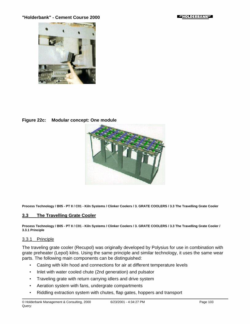
"Holderbank" - Cement Course 2000
© Holderbank Management & Consulting, 2000 6/23/2001 - 4:34:27 PM Page 103Query:
Figure 22c: Modular concept: One module
Process Technology / B05 - PT II / C01 - Kiln Systems / Clinker Coolers / 3. GRATE COOLERS / 3.3 The Travelling Grate Cooler
3.3 The Travelling Grate Cooler
Process Technology / B05 - PT II / C01 - Kiln Systems / Clinker Coolers / 3. GRATE COOLERS / 3.3 The Travelling Grate Cooler /3.3.1 Principle
3.3.1 Principle
The traveling grate cooler (Recupol) was originally developed by Polysius for use in combination withgrate preheater (Lepol) kilns. Using the same principle and similar technology, it uses the same wearparts. The following main components can be distinguished:
• Casing with kiln hood and connections for air at different temperature levels
• Inlet with water cooled chute (2nd generation) and pulsator
• Traveling grate with return carrying idlers and drive system
• Aeration system with fans, undergrate compartments
• Riddling extraction system with chutes, flap gates, hoppers and transport

"Holderbank" - Cement Course 2000
© Holderbank Management & Consulting, 2000 6/23/2001 - 4:34:27 PM Page 104Query:
• Clinker crusher
♦ Material transportThe clinker is carried by a horizontal traveling grate which works like a stationary caterpillar chainwith perforated chain plates. In contrast to the reciprocating grate cooler, the clinker does nottumble over plate edges, but remains as undisturbed layered bed from inlet to discharge.
♦ Heat exchangeHeat exchange takes place, like for the reciprocating grate according to the cross currentprinciple. Because the layers remain, it should be even better, at least theoretically.
♦ Cooling airAmbient air is blown by a number of cooling air fans to underneath of the travelling grate platescarrying the clinker. Pressure and flow criteria of cooling air are basically as for the reciprocatinggrate cooler.
♦ Water cooled inlet chuteIn order to achieve rapid cooling in the inlet section, but also to protect the travelling grate from thehighest clinker temperatures, Recupol coolers were equipped with a water cooled inlet chute.
♦ Key figures / KPISpecific grate loading: 25 - 30 t/d m2 (design)Largest units: 3000 t/d (Lägerdorf kiln 10)
♦
Figure 23 Travelling grate cooler
Process Technology / B05 - PT II / C01 - Kiln Systems / Clinker Coolers / 3. GRATE COOLERS / 3.3 The Travelling Grate Cooler /3.3.2 Strengths and Weaknesses
3.3.2 Strengths and Weaknesses
Travelling grate cooler compared to reciprocating coolers:
Strengths Weaknesses

"Holderbank" - Cement Course 2000
© Holderbank Management & Consulting, 2000 6/23/2001 - 4:34:27 PM Page 105Query:
Strengths Weaknesses
• Possibility of replacing grate platesduring operation (on the returning part)
• Undisturbed, layered clinker bed isbetter for optimum heat exchange
• Larger machine for the samegrate area equipment requiringmore space and higher civil cost
• Lower specific grate loadingsadding further to overall size
• More expensive to build than areciprocating grate cooler
• The absence of clinkermovement (see above) wasoften considered a disadvantagebecause of cases where a solid(fritted) layer on top of theclinker bed made it impermeablefor air. For this reason, pulsatorswere installed for first coolingfans.
• Much higher maintenancerequirement with ageingequipment
• Heat loss via cooling water forinlet chute
Due to the mentioned weaknesses, Polysius eventually decided to develop their own reciprocatinggrate cooler (Repol) around 1980:
Figure 24 Travelling grate cooler: Design details
Process Technology / B05 - PT II / C01 - Kiln Systems / Clinker Coolers / 4. ROTATING COOLERS
4. ROTATING COOLERS
Process Technology / B05 - PT II / C01 - Kiln Systems / Clinker Coolers / 4. ROTATING COOLERS / 4.1 The Rotary Cooler or TubeCooler

"Holderbank" - Cement Course 2000
© Holderbank Management & Consulting, 2000 6/23/2001 - 4:34:28 PM Page 106Query:
4.1 The Rotary Cooler or Tube Cooler
Process Technology / B05 - PT II / C01 - Kiln Systems / Clinker Coolers / 4. ROTATING COOLERS / 4.1 The Rotary Cooler or TubeCooler / 4.1.1 Principle
4.1.1 Principle
The rotary cooler consists mainly of a rotating cylinder, similar to a rotary kiln.
The clinker is fed through the inlet chute and is then cooled by air while being transported towards theoutlet end. Cooling is performed in countercurrent flow. The tube is equipped with internal lifters whichimprove the heat transfer. About 2/3 (66%) of the cooler length is lined with refractory bricks.
The rotary cooler is of simple design and is the oldest type of clinker coolers. It was seldom used formodern, large kiln systems. Therefore comparatively little design and operating experience isnowadays available for rotary coolers above 2000 t/d. However, the application of rotary coolers stilloffers certain advantages. Presently units up to 4500 t/d (dimensions dia 6.3/6.0 x 80 m) are inoperation. It will be interesting to follow the future development of large rotary coolers.
Process Technology / B05 - PT II / C01 - Kiln Systems / Clinker Coolers / 4. ROTATING COOLERS / 4.1 The Rotary Cooler or TubeCooler / 4.1.2 Design Features
4.1.2 Design Features
♦ Arrangement of the rotary cooler is normally in the extension of the kiln axis; in many cases thereverse manner (underneath the kiln) has been applied.
♦ The diameter of the cooler is similar to that of a corresponding suspension preheater kiln. Likewisethe rotating speed is in the same range as for the kiln (max. 3 rpm). Length/diameter ratio: L/D ~10.
Many cooler tubes are designed with an extension in diameter in order to reduce air velocity.
♦ The inclination is comparatively high (in the order of 5%).
♦ Like for all rotating coolers, the internal heat transfer equipment is an important part of the rotarycooler. Its task is to generate additional area by scattering the clinker without generating too muchdust. Basically a similar design may be applied as in a planetary cooler tube (see next chapter)however the following differences must be considered:
• The clinker falling heights are larger. Wear protection of shell and lining is essential.
• At a comparative length position the clinker in a rotary cooler is hotter than in a planetarycooler.
Figure 25 Rotary cooler

"Holderbank" - Cement Course 2000
© Holderbank Management & Consulting, 2000 6/23/2001 - 4:34:28 PM Page 107Query:
The following zones can typically be distinguished in a rotary cooler (simplified):
A Lined inlet zone
B Lined crushing teeth zone(metallic teeth)
C Lined cast lifter zone, lining protected by wearing plates(at least in the second half)
D Cast lifter zone, shell protected by wearing plates(having air gap, giving also insulating effect)
E Sheet metal zone with wearing plates
Construction materials have to be selected according to the high temperature and wear requirements.
Process Technology / B05 - PT II / C01 - Kiln Systems / Clinker Coolers / 4. ROTATING COOLERS / 4.1 The Rotary Cooler or TubeCooler / 4.1.3 Cooling performance
4.1.3 Cooling performance
Depending on the design and the shape of the lifters clinker outlet temperature usually tends to behigh. In many cases it is necessary to enhance the cooling by injecting water into the tube (up to 60g/kg clinker) in order to reach reasonably low clinker temperatures of 100° to 150°C.
The cooling efficiency (heat recuperation) is equal or even slightly better than on a planetary cooler.
Process Technology / B05 - PT II / C01 - Kiln Systems / Clinker Coolers / 4. ROTATING COOLERS / 4.1 The Rotary Cooler or TubeCooler / 4.1.4 Strengths / Weaknesses
4.1.4 Strengths / Weaknesses
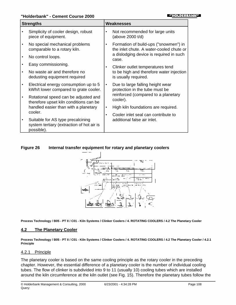
"Holderbank" - Cement Course 2000
© Holderbank Management & Consulting, 2000 6/23/2001 - 4:34:28 PM Page 108Query:
Strengths Weaknesses
• Simplicity of cooler design, robustpiece of equipment.
• No special mechanical problemscomparable to a rotary kiln.
• No control loops.
• Easy commissioning.
• No waste air and therefore nodedusting equipment required
• Electrical energy consumption up to 5kWh/t lower compared to grate cooler.
• Rotational speed can be adjusted andtherefore upset kiln conditions can behandled easier than with a planetarycooler.
• Suitable for AS type precalciningsystem tertiary (extraction of hot air ispossible).
• Not recommended for large units(above 2000 t/d)
• Formation of build-ups ("snowmen") inthe inlet chute. A water-cooled chute ora dislodging device is required in suchcase.
• Clinker outlet temperatures tend to be high and therefore water injectionis usually required.
• Due to large falling height wearprotection in the tube must bereinforced (compared to a planetarycooler).
• High kiln foundations are required.
• Cooler inlet seal can contribute toadditional false air inlet.
Figure 26 Internal transfer equipment for rotary and planetary coolers
Process Technology / B05 - PT II / C01 - Kiln Systems / Clinker Coolers / 4. ROTATING COOLERS / 4.2 The Planetary Cooler
4.2 The Planetary Cooler
Process Technology / B05 - PT II / C01 - Kiln Systems / Clinker Coolers / 4. ROTATING COOLERS / 4.2 The Planetary Cooler / 4.2.1Principle
4.2.1 Principle
The planetary cooler is based on the same cooling principle as the rotary cooler in the precedingchapter. However, the essential difference of a planetary cooler is the number of individual coolingtubes. The flow of clinker is subdivided into 9 to 11 (usually 10) cooling tubes which are installedaround the kiln circumference at the kiln outlet (see Fig. 15). Therefore the planetary tubes follow the

"Holderbank" - Cement Course 2000
© Holderbank Management & Consulting, 2000 6/23/2001 - 4:34:28 PM Page 109Query:
kiln rotation. Because of their connection to the kiln rotation, planetary coolers do not need a separatedrive. This fact already illustrates one main advantage of the planetary cooler: its simplicity inoperation.
Strictly speaking the cooling of clinker does not only start in the cooling tubes but already in the kiln. Inthe case of a planetary cooler the kiln burner pipe is always inserted into the rotary kiln so that acooling zone behind the flame of 1.5 to 2.5 kiln diameters is created. This zone is called the "kilninternal cooling" zone and must be considered as an integral part of any planetary cooler. In this zonethe temperature of the clinker drops from 1450° to 1200 - 1300°C. This temperature reduction isimportant for the protection of the inlet opening, the elbow and the first section of the cooling tubes.
After this first cooling in the kiln internal cooling zone the clinker falls into the elbows when they reachtheir lowest point of kiln rotation. The hot clinker is then cooled by air in counterflow (the amount of airequals the amount of secondary air). The air is heated up to approx. 700°C. The clinker reaches finaltemperatures which are typically in the range of 140° to 240°C.
A considerable amount of heat is also transferred to ambient by radiation and convection since approx.75% of the cooler shell is not insulated.
Process Technology / B05 - PT II / C01 - Kiln Systems / Clinker Coolers / 4. ROTATING COOLERS / 4.2 The Planetary Cooler / 4.2.2Historical
4.2.2 Historical
Planetary coolers have been used since 1920. When large kiln units and grate coolers were developedplanetary coolers were abandoned for many years. But about 1966 planetary coolers of largecapacities were introduced. At that stage serious mechanical problems occurred on these first largeplanetary coolers. As a consequence a lot of work had to be done in order to improve the mechanicaldesign of planetary coolers. As a result of extensive computer calculations and operating experiencethe planetary cooler became a mechanically reliable piece of equipment.
In the late 1970's, the design had reached a high standard and a considerable level of perfection. Unitsof up to 5000 t/d were envisaged. With the demand for permanently larger units using precalcinertechnology with separate tertiary air dusts, the boom period of the planetary coolers came to an end.
Figure 27 Planetary cooler
Process Technology / B05 - PT II / C01 - Kiln Systems / Clinker Coolers / 4. ROTATING COOLERS / 4.2 The Planetary Cooler / 4.2.3Design features
4.2.3 Design features

"Holderbank" - Cement Course 2000
© Holderbank Management & Consulting, 2000 6/23/2001 - 4:34:29 PM Page 110Query:
Planetary coolers in the late 1970's had the following design features:
♦ Shell extension:The kiln shell is extended beyond the cooling tube outlets and is supported by an additional rollerstation.
♦ Fixation of cooling tubes:Fixed support of cooling tubes near inlet and loose support near outlet end.
With larger coolers, the cooling tubes can consist of two separate sections requiring three supports. Inthat case two fixed supports are located near inlet and near outlet and a loose support is located at theinterconnection point in the middle.
♦ Design of cooler supports:The kiln shell is reinforced (high thickness) where the cooler support structure for the cooler iswelded on. The support structure (base and brackets) itself is of heavy design consisting ofreinforcement ribs and box beams.
♦ Cooler length:Length/diameter ratio of tubes is approx. 10:1
♦ Inlet openings:The inlet openings to the cooler elbows weaken the kiln shell and high mechanical and thermalstresses occur in that zone. The openings are made of oval shape and the kiln shell is considerably reinforced in its thickness(up to 140 mm in large kilns) in order to compensate for the weakening. In some cases a diagonal retaining bar (made of high heat resistant steel) is incorporated in theopening in order to avoid that large lumps can enter the cooler.
♦ Kiln-to-elbow joint:This joint is designed in a manner that no forces due to thermal expansion and deformation aretransmitted from elbow to kiln.
♦ Elbow:In order to prevent that clinker is falling back into the kiln while the opening is on top position, theposition of the cooling tube is displaced back against the direction of rotation. The elbow designmust avoid excessive dust backspillage and wear.
Process Technology / B05 - PT II / C01 - Kiln Systems / Clinker Coolers / 4. ROTATING COOLERS / 4.2 The Planetary Cooler / 4.2.4Internal heat transfer equipment (see Fig. 26)
4.2.4 Internal heat transfer equipment (see Fig. 26)
Cooling performance depends strongly on efficient lifters of solid and durable design. Since high heatresistant metallic lifers are available on the market also the high temperature zones can be adequatelyequipped. Special high temperature alloys can be used for this purpose. They can withstand maximumtemperatures of up to 1150°C. These alloys are usually characterized by a high chromium content ofapprox. 30% Cr. Other elements as Ni or Mo can occur in various proportions. Fig. 26 shows a typicalarrangement of heat transfer internals. Breaking teeth are applied in the hottest zone. They are able tocrush large lumps of clinker and create also a tumbling effect, which improves the heat transfer. Theyare of heavy design and mounted on separate supports.
The first rows of lifters must be carefully selected regarding design and material. Their functioning isvery important since they also protect the following lifters from overheating.
Figure 28a Temperature profile in planetary cooler

"Holderbank" - Cement Course 2000
© Holderbank Management & Consulting, 2000 6/23/2001 - 4:34:29 PM Page 111Query:
Figure 28b Water cooling for planetary coolers
Process Technology / B05 - PT II / C01 - Kiln Systems / Clinker Coolers / 5. VERTICAL COOLERS
5. VERTICAL COOLERS
Process Technology / B05 - PT II / C01 - Kiln Systems / Clinker Coolers / 5. VERTICAL COOLERS / 5.1 The Gravity Cooler (G -Cooler)
5.1 The Gravity Cooler (G - Cooler)
The Claudius Peters Company have developed the “g-cooler”. The letter "g" stands for gravity sinceclinker movement is performed by gravity.
This cooler is designed as an after cooler and can therefore only be used in connection with a primarycooler such as a short grate cooler or a planetary cooler. The installation together with a grate cooler isshown in Fig. 29.
An intermediary crusher reduces the clinker size to 20 - 30 mm. The material of approx. 400°C is thenfilled by a drag chain into a vertical shaft. Cooling is performed by horizontal rows of tubes which arecooled by internal air flow. The heat is therefore exchanged indirectly and the air remains dust-free.The clinker slowly drops down (at a speed of 20 – 30 mm/s) and reaches final temperatures of approx.100°C at the discharge.

"Holderbank" - Cement Course 2000
© Holderbank Management & Consulting, 2000 6/23/2001 - 4:34:29 PM Page 112Query:
There is no dedusting equipment required for the cooling air. However, the system according to Fig. 29as a whole is usually not free from dusty waste air. In case of a suspension preheater kiln system thereis still some waste air required on the grate cooler since the kiln cannot take all the hot air producedduring the first cooling step. In addition, a marginal amount of dusty air is produced by the g-cooleritself (top and discharge).
The application of this cooler type is often considered for kiln extension projects. If an existing gratecooler (or a planetary cooler) has to be operated at higher capacity the new clinker outlet temperaturecan become too high. In this case the clinker temperature can be reduced by a g-cooler used as anaftercooler.
Process Technology / B05 - PT II / C01 - Kiln Systems / Clinker Coolers / 5. VERTICAL COOLERS / 5.2 The Shaft Cooler
5.2 The Shaft Cooler
A shaft cooler can be operated waste-air-free and theoretically offers an ideal countercurrent heatexchange and thus high recuperating efficiency. Based on the idea the first large shaft cooler wasdesigned and constructed on a 3000 t/d kiln in 1973.
The experience gained in the plant shows that it is possible to operate such equipment but someserious disadvantages have to be taken into account:
♦ All depends of the clinker granulometry! Theoretically, an extremely uniform clinker granulometryhaving no fines and no coarse material would be required. This is hardly achievable in a cementkiln. Therefore, fluctuations occur.
♦ High cooling air quantity (= secondary air) of 1.05 Nm3/kg cli is required but even so the clinker exittemperature of 350°C is very high.
♦ High power consumption (10 kWh/t)
For the above reasons, the technical realization is not yet solved. The shaft cooler so far is not areasonable alternative to the conventional clinker coolers.
Figure 29 Gravity cooler (g-cooler, CPAG)
Figure 30 Shaft cooler

"Holderbank" - Cement Course 2000
© Holderbank Management & Consulting, 2000 6/23/2001 - 4:34:30 PM Page 113Query:
Figure 31 Claudius Peters CPAG: Combi Cooler
Figure 32 FLS: Coolax Grate Cooler
Figure 33 Fuller: Controlled Flow Grate (CFG) Cooler

"Holderbank" - Cement Course 2000
© Holderbank Management & Consulting, 2000 6/23/2001 - 4:34:30 PM Page 114Query:
Figure 34 IKN: Pendulum Cooler
Figure 35 KHD: Pyrostep Cooler
Figure 36 Polysius: Repol RS Cooler

"Holderbank" - Cement Course 2000
© Holderbank Management & Consulting, 2000 6/23/2001 - 4:34:31 PM Page 115Query:

"Holderbank" - Cement Course 2000
© Holderbank Management & Consulting, 2000 6/23/2001 - 4:34:32 PM Page 116Query:
Process Technology / B05 - PT II / C02 - Internal Kiln Fittings
C02 - Internal Kiln Fittings

"Holderbank" - Cement Course 2000
© Holderbank Management & Consulting, 2000 6/23/2001 - 4:34:32 PM Page 117Query:
Process Technology / B05 - PT II / C02 - Internal Kiln Fittings / Kiln Chain Systems
Kiln Chain SystemsA. ObristPT 96/ 14036 / E
1. INTRODUCTION
2. Functions of a Kiln Chain System
2.1 Heat Exchange
2.2 Cleaning of the Kiln Shell
2.3 Transport of Material
2.4 Reduce Dust Emissions
3. Individual Zones of a Chain System
3.1 Free Zone of the Kiln Inlet
3.2 Dust Curtain Zone
3.3 Plastic Zone
3.4 Granular Zone (Preheating Zone)
3.5 Heat Resistant Zone
1.6 Main Characteristic Data of the Individual Chain System Zones
4. Arrangement of Chains
4.1 Straight Curtain
4.2 Spiral Zone
1.3 Multiple Spiral Curtain
1.4 Triangular Curtain (Z-Curtain)
1.5 Garlands
1.6 Festoons
1.7 Spiral Garlands
1.8 Thermochains
5. Types of Chain Links
5.1 Round Links
5.2 Long Links
5.3 Oval Links
5.4 Other Types of Chain Links
6. Chain Material
6.1 Mild Steel Chains

"Holderbank" - Cement Course 2000
© Holderbank Management & Consulting, 2000 6/23/2001 - 4:34:33 PM Page 118Query:
6.2 Heat Resistant Alloy Chains
7. Chain Hangers
8. Main Characteristic Data of Chain Systems
9. ANNEXES
10. LITERATURE
11. Test Questions

"Holderbank" - Cement Course 2000
© Holderbank Management & Consulting, 2000 6/23/2001 - 4:34:33 PM Page 119Query:
Summary:
A kiln chain system has four main functions:
♦ It helps to increase the heat exchange between gas and raw meal
♦ It keeps the kiln shell (lining surface) clean
♦ It assists the transport of material through the kiln tube
♦ It helps to reduce the dust emission
A properly designed chain system must respect the changing properties of material passing throughthe kiln tube. In a wet process kiln the material is fed as a liquid slurry and changes it propertiessubsequently in several steps inside the chain system to dry preheated granules. In accordance withthe changing material properties different arrangement of chains (straight curtains, spirals, garlands,etc.) have to be used for individual parts of the system to satisfy the specific requirements. Also thechain densities and the height of the free tunnel below the chains have to be selected carefully in orderto reach the maximum efficiency.
The chain links can have different shapes (round, long, oval etc.), preferably round links. The chemicalcomposition of the chains' alloy and its physical treatment (hardening) strongly influence the life time ofthe system.
Different types of chain hangers can be used (single or multiple hangers, with or without shackles etc.).They have to guarantee a sufficient stability, to enable an easy installation and they should as far aspossible assist the function of the chains.
NOMENCLATURE
Just a few symbols and names are to be explained before starting this lecture, the other ones will beexplained in the respective chapters.
Figure:
Dis Diameter inside kiln steel shell
DIL Diameter inside kiln lining
hfr Theoretical free height under the chains (see attached sketch),expressed in mm or as % of DIL

"Holderbank" - Cement Course 2000
© Holderbank Management & Consulting, 2000 6/23/2001 - 4:34:34 PM Page 120Query:
expressed in mm or as % of DIL
density of chains m2/m3 is calculated for individual parts (zones) of the system as the totalsurface area of chains in the respective zone divided by thevolume inside lining of this zone
density of chains kg/m3 similar to the above mentioned density, but concerns the weight ofchains instead of their surface
Process Technology / B05 - PT II / C02 - Internal Kiln Fittings / Kiln Chain Systems / 1. INTRODUCTION
1. INTRODUCTION
Wet process kilns cannot be successfully operated without internal kiln fittings, among which the kilnchains are the most typical and most frequently used ones. The number of existing wet process kilns isstill high (~33% in "Holderbank" Group) and a conversion from wet to dry process is very expensive. Byimproving the existing chain systems or, where necessary, by installing a completely new chainsystem, the kiln operation can be upgraded considerably with relatively moderate investment costs.
Process Technology / B05 - PT II / C02 - Internal Kiln Fittings / Kiln Chain Systems / 2. FUNCTIONS OF A KILN CHAIN SYSTEM
2. FUNCTIONS OF A KILN CHAIN SYSTEM
The kiln chain system has 4 main functions:
Process Technology / B05 - PT II / C02 - Internal Kiln Fittings / Kiln Chain Systems / 2. FUNCTIONS OF A KILN CHAIN SYSTEM / 2.1Heat Exchange
2.1 Heat Exchange
The heat exchange between hot gases and the raw material depends on the surface area exposed tothe hot medium. In the parts of kiln where no chains are installed, this surface area consists of thesurface of the material layer on the kiln bottom and of the surface of the remaining part of the kiln shell(resp. lining). By installing the chains a large additional surface area can be gained, exceeding that onementioned above several times (up to 10 times and more) in the respective part of the kiln. Byimproving the heat exchange the specific heat demand is reduced and the kiln output is increased.
In Fig. 1 different positions of a chain during one kiln rotation are shown. In position 1 the chain isexposed to the stream of hot gases and thus heated up. The cooling of the chain (which passes itsheat to the layer of material) starts in position 2, continues in position 3 and ends in position 4.
Figure 1:

"Holderbank" - Cement Course 2000
© Holderbank Management & Consulting, 2000 6/23/2001 - 4:34:34 PM Page 121Query:
Process Technology / B05 - PT II / C02 - Internal Kiln Fittings / Kiln Chain Systems / 2. FUNCTIONS OF A KILN CHAIN SYSTEM / 2.2Cleaning of the Kiln Shell
2.2 Cleaning of the Kiln Shell
In the upper part of the kiln the characteristics of the wet, sticky raw material favors the formation ofmud coating and mud rings. This would reduce the free kiln cross sectional area and thus obstruct theflow of material and gases. Growing mud rings make the kiln operation difficult. It is one of the mainfunctions of the chain system to keep the internal kiln shell surface clean, free of coating or rings. Dueto the kiln rotation the chains slide on the kiln shell (resp. lining) and destroy the rings and the coating.The sliding movement of a chain cleaning the kiln shell is shown in Fig. 1 (position 3).
Process Technology / B05 - PT II / C02 - Internal Kiln Fittings / Kiln Chain Systems / 2. FUNCTIONS OF A KILN CHAIN SYSTEM / 2.3Transport of Material
2.3 Transport of Material
The properties of material in different parts of the kiln differ considerably. In some sections of the upperpart of the kiln, where the material is sticky and plastic, its transporting is more difficult than in othersections.
As a regular flow of material is of an eminent importance for a smooth kiln operation, it is necessary toinstall material flow assisting devices in some sections. Some special arrangements of chains can helpto draw the material through the critical sections. This can be achieved by chains moving in the desireddirection (garlands) or by a screw shaped arrangement of the chain fastening points. Otherarrangements of chains can be an obstruction to the flow of material and should therefore never beused in the critical sections.
Process Technology / B05 - PT II / C02 - Internal Kiln Fittings / Kiln Chain Systems / 2. FUNCTIONS OF A KILN CHAIN SYSTEM / 2.4Reduce Dust Emissions
2.4 Reduce Dust Emissions
The gases leaving the kiln contain a certain amount of dust consisting mainly of partly calcined, hot rawmaterial. The dust load of gases depends on the properties of the raw material and on the specificconditions of the kiln operation. Dust loss should be kept small, it means a loss of heat and material.The kiln chain system, mainly its upper part, can help to reduce the dust emission. Dust particlescarried by the stream of gases stick to the wet surface of chains and later when these chains areemerged into the layer of material, this dust is passed over to the slurry.
Process Technology / B05 - PT II / C02 - Internal Kiln Fittings / Kiln Chain Systems / 3. INDIVIDUAL ZONES OF A CHAIN SYSTEM

"Holderbank" - Cement Course 2000
© Holderbank Management & Consulting, 2000 6/23/2001 - 4:34:34 PM Page 122Query:
3. INDIVIDUAL ZONES OF A CHAIN SYSTEM
The material passing the chain system changes subsequently its properties - it loses water and isheated up. According to the different material properties the total chain system can be divided intoseveral zones. These zones are:
Process Technology / B05 - PT II / C02 - Internal Kiln Fittings / Kiln Chain Systems / 3. INDIVIDUAL ZONES OF A CHAIN SYSTEM /3.1 Free Zone of the Kiln Inlet
3.1 Free Zone of the Kiln Inlet
This short zone is considered to be a part of the chain system in spite of the fact that no chains areinstalled here. A sufficient amount of slurry should be accumulated in this zone in order to guarantee aconstant and regular flow into the lower parts of the system.
Good results have been obtained with the zone length of 1 to 1.5 kiln diameters.
Process Technology / B05 - PT II / C02 - Internal Kiln Fittings / Kiln Chain Systems / 3. INDIVIDUAL ZONES OF A CHAIN SYSTEM /3.2 Dust Curtain Zone
3.2 Dust Curtain Zone
The dust curtain zone is relatively short, its length does not exceed 0.5 DIL under normal conditions.
The material entering this zone still has the relatively good flow properties of the kiln feed (slurry).When leaving this zone, the material has a lower water content and becomes more "plastic",essentially due to the inter-mixing of the dust previously retained by the chains in this zone.
In order to achieve a good dust catching efficiency, the density of chains must be high (some 8 to 15m2/m3) and the free height below the chains should be 18 - 27% of DIL.
Process Technology / B05 - PT II / C02 - Internal Kiln Fittings / Kiln Chain Systems / 3. INDIVIDUAL ZONES OF A CHAIN SYSTEM /3.3 Plastic Zone
3.3 Plastic Zone
The length of this zone depends on properties of raw material, slurry moisture, characteristics of thekiln operation etc. and can vary in a wide range (approx. between 1.5 and 4 DIL). The material in thiszone is plastic and sticky, still relatively cold and wet and because of these properties it favors mudcoating and mud ring formation. The transport of material through this zone is the most difficult oneamong all the zones of the chain system.
Due to the material properties mentioned above the chains in this zone must have a good shellcleaning and material transporting efficiency. The density of chains should be relatively low, some 5 to8 m2/m3. As to achieve a big free tunnel under the chains, the free height hfr should be approx. 30%or, if garland chains are installed in this zone, some 40%. Heavier (thick wire) chains should beinstalled.
In order to be sure that the zone of plastic material will always stay inside the zone of chains which cantreat it successfully, the respective arrangement of chains should be slightly extended in thedownstream direction as to obtain a sufficient safety.
Process Technology / B05 - PT II / C02 - Internal Kiln Fittings / Kiln Chain Systems / 3. INDIVIDUAL ZONES OF A CHAIN SYSTEM /3.4 Granular Zone (Preheating Zone)

"Holderbank" - Cement Course 2000
© Holderbank Management & Consulting, 2000 6/23/2001 - 4:34:35 PM Page 123Query:
3.4 Granular Zone (Preheating Zone)
The recommendable length of this zone depends on the desired material temperature and the restwater content at its discharge end. Good results have been achieved with a zone length between 2 and4,5 DIL.
The material entering this zone is not plastic any more, it forms granules which are easy to betransported and do not favor a mud ring formation. The granules should be dried and heated up in thiszone.
The chains should heat the material gently without unnecessary dust generation, they should enable agood heat exchange. Lighter (thin wire) chains should therefore be installed. A chain density of approx.6 to 10 m2/m3 and a free height of approx. 25 to 30% can be recommended. This zone is sometimesdivided into an upper and a lower part. Both parts have the same (or at least a similar) arrangement,but the lower part has a higher density of chains than the upper one. The damming effect of the lowerpart, caused by the thicker layer of chains on the kiln bottom, helps to increase the material retentiontime and improves the heat exchange.
Process Technology / B05 - PT II / C02 - Internal Kiln Fittings / Kiln Chain Systems / 3. INDIVIDUAL ZONES OF A CHAIN SYSTEM /3.5 Heat Resistant Zone
3.5 Heat Resistant Zone
This zone is relatively short, its length does not exceed 1,5 DIL. The material, dry and hot granules, caneasily be transported. A very gentle treatment of the material is required in order to keep the dustcreation as low as possible.
The main function of the chains is to protect the upstream part of the system against heat radiation andtoo high a gas temperature. Chains made of heat resistant steel should be installed in this zone.Lighter (thin wire) chains should be preferred.
Process Technology / B05 - PT II / C02 - Internal Kiln Fittings / Kiln Chain Systems / 3. INDIVIDUAL ZONES OF A CHAIN SYSTEM /3.6 Main Characteristic Data of the Individual Chain System Zones
3.6 Main Characteristic Data of the Individual Chain System Zones
Table 1
Zone
Free Dust Plastic Granular Heat
Curtain Upper Lower Resistant
Length DIL ≤ 1,5 ≤ 0.5 1.5 to 4 1 to 3 ≤ 1,5 ≤ 1,5
hfr % DIL 18 - 27 40 / 30 25 to 30
Density m2/m3 8 to 15 5 to 8 6 to 10
Moisture % 30 to 40 15 - 25
Material temp. °C 20 100 <600
Chain temp. °C <400 <1'000
Gas temp. °C 160 to 240 <1'100
Material flow

"Holderbank" - Cement Course 2000
© Holderbank Management & Consulting, 2000 6/23/2001 - 4:34:35 PM Page 124Query:
Process Technology / B05 - PT II / C02 - Internal Kiln Fittings / Kiln Chain Systems / 4. ARRANGEMENT OF CHAINS
4. ARRANGEMENT OF CHAINS
Each individual zone of a chain system must have its own specific properties in order to satisfy therequirements mentioned previously.
Process Technology / B05 - PT II / C02 - Internal Kiln Fittings / Kiln Chain Systems / 4. ARRANGEMENT OF CHAINS / 4.1 StraightCurtain
4.1 Straight Curtain
As shown in Fig. 2, this arrangement of chains is very simple. The chain fastening points form a ring.Several straight curtains are combined to a straight curtain zone. The distance between the individualstraight curtains (rings or rows) should not be too long, this would lead - in order to achieve a sufficientdensity - to too great a number of chains per ring and thus to big heaps of chains on the kiln bottomobstructing the flow of material.
Figure 2: Straight Curtain
The main advantages of a straight curtain are its simple design and installation as well as an easymaintenance. Its main disadvantages are the poor shell cleaning efficiency and the fact that thisarrangement does not assist the transport of material. The straight curtains should therefore not beused in the plastic zone or in the dust curtain, but they can be recommended for the granular zone.
Process Technology / B05 - PT II / C02 - Internal Kiln Fittings / Kiln Chain Systems / 4. ARRANGEMENT OF CHAINS / 4.2 Spiral Zone
4.2 Spiral Zone
In a spiral curtain the chain fastening points follow the screw lines on the kiln shell.
The spiral (screw) lines should have an inclination of approx. 30° (see Fig. 3). In order to assist thetransport of material, the inclination must have the proper sense, i.e. the sense of rotation must betaken into consideration.
Figure 3: Spiral Curtain (4-start spiral)

"Holderbank" - Cement Course 2000
© Holderbank Management & Consulting, 2000 6/23/2001 - 4:34:35 PM Page 125Query:
The arrangement with 4 screw lines per circumference, called a 4-start spiral, is most frequently used. This arrangement allows for a good shell cleaning effect and at thesame time overlapping of chains can be avoided, as shown in Fig. 4a. The recommended chain lengthis namely approx. 0.7 D, and the circumferential distance between adjacent screw lines is π D/4 = 0.78D.
The benefits of this solution become clear if we compare it with other arrangements having a differentnumber of screw lines. An arrangement with less than 4 screw lines per circumference (Fig. 4b) doesnot enable a full shell cleaning effect, because some parts of the shell have no contact with a chain. Anarrangement with more than 4 screw lines leads necessarily to overlapping of chains (Fig. 4c) and thusto a higher layer of chains on the kiln bottom which is not favorable for the transport of material.
Figure 4a-c:
The very good material transporting and the good shell cleaning efficiency are the main advantages ofa spiral curtain. Its disadvantages are a slightly smaller heat exchanging efficiency, a more difficultbrick lining work and a limited maximum chain density. For these reasons, the spiral curtainarrangement should not be used in the granular zone but it can be recommended for the plastic zone.
Process Technology / B05 - PT II / C02 - Internal Kiln Fittings / Kiln Chain Systems / 4. ARRANGEMENT OF CHAINS / 4.3 MultipleSpiral Curtain
4.3 Multiple Spiral Curtain
A spiral curtain having 8 or more spirals per circumference is called a multiple spiral curtain. Such anarrangement enables to achieve high chain densities and the passages between chains are narrow,therefore, it can be used in the dust curtain zone. its material transporting efficiency is not as good as

"Holderbank" - Cement Course 2000
© Holderbank Management & Consulting, 2000 6/23/2001 - 4:34:36 PM Page 126Query:
that one of a 4-start spiral, but it is still better than that one of any other arrangement enabling asimilarly high chain density. A multiple spiral arrangement can therefore be recommended for dustcurtain zones in such cases where the kiln feed flow properties are poor.
Process Technology / B05 - PT II / C02 - Internal Kiln Fittings / Kiln Chain Systems / 4. ARRANGEMENT OF CHAINS / 4.4 TriangularCurtain (Z-Curtain)
4.4 Triangular Curtain (Z-Curtain)
In a triangular curtain, also called Z-curtain, the chain fastening points follow a zig-zag line (see Fig. 5).This arrangement enables to reach high chain densities without obstructing the flow of material andgases too much. Because of the equal distribution of chains the heap of chains on the kiln bottom isnot too high in spite of the high chain density (see Fig. 6).
Figure 5 & 6
The arrangement with angles of 60° and with 8 "triangles" per kiln circumference has proved to be themost successful one. In such an arrangement the layer of chains on the kiln bottom is only approx. 4chains high (because 8 triangles have all together 16 fastening lines and the chain length of approx.0.73 D corresponds to ≈ π D/4, therefore, each chain passes 16/4 = 4 lines).
The dust catching efficiency of such an arrangement is very good, it was therefore used in the dustcurtain zone in such cases where the kiln feed flow properties are relatively good. Frequently onesingle triangular curtain was installed, but two are also possible.
Nowadays, for dust curtains a multiple start spiral arrangement is preferred to a triangular curtainbecause of its material transport efficiency.
Process Technology / B05 - PT II / C02 - Internal Kiln Fittings / Kiln Chain Systems / 4. ARRANGEMENT OF CHAINS / 4.5 Garlands
4.5 Garlands
Chains having their both ends fastened to the kiln shell are called garlands (Fig. 7) The fasteningpoints form straight rings in the kiln shell. The shape of a garland is characterized by the chain length,by the axial distance LAX and by the angle ∝ (see Fig. 7 and 8). Good results have been achieved withan angle ∝ ≈ 90 to 110° and a distance LAX ≈ 0.5 to 0.9 D.
Figure 7 & 8:
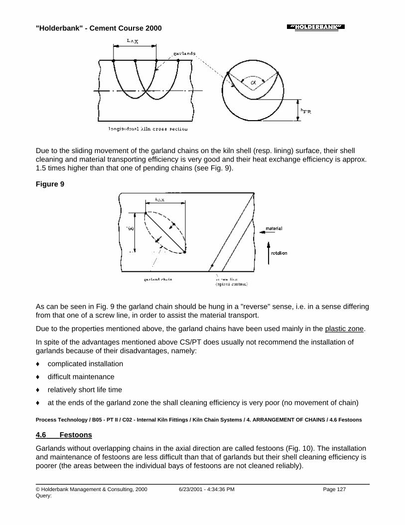
"Holderbank" - Cement Course 2000
© Holderbank Management & Consulting, 2000 6/23/2001 - 4:34:36 PM Page 127Query:
Due to the sliding movement of the garland chains on the kiln shell (resp. lining) surface, their shellcleaning and material transporting efficiency is very good and their heat exchange efficiency is approx.1.5 times higher than that one of pending chains (see Fig. 9).
Figure 9
As can be seen in Fig. 9 the garland chain should be hung in a "reverse" sense, i.e. in a sense differingfrom that one of a screw line, in order to assist the material transport.
Due to the properties mentioned above, the garland chains have been used mainly in the plastic zone.
In spite of the advantages mentioned above CS/PT does usually not recommend the installation ofgarlands because of their disadvantages, namely:
♦ complicated installation
♦ difficult maintenance
♦ relatively short life time
♦ at the ends of the garland zone the shall cleaning efficiency is very poor (no movement of chain)
Process Technology / B05 - PT II / C02 - Internal Kiln Fittings / Kiln Chain Systems / 4. ARRANGEMENT OF CHAINS / 4.6 Festoons
4.6 Festoons
Garlands without overlapping chains in the axial direction are called festoons (Fig. 10). The installationand maintenance of festoons are less difficult than that of garlands but their shell cleaning efficiency ispoorer (the areas between the individual bays of festoons are not cleaned reliably).

"Holderbank" - Cement Course 2000
© Holderbank Management & Consulting, 2000 6/23/2001 - 4:34:37 PM Page 128Query:
Figure 10
Process Technology / B05 - PT II / C02 - Internal Kiln Fittings / Kiln Chain Systems / 4. ARRANGEMENT OF CHAINS / 4.7 SpiralGarlands
4.7 Spiral Garlands
An arrangement of garlands where the chain fastening points form screw lines ("spirals") is calledspiral garlands. Its material transporting efficiency is even better than that one of normal straightgarland zone, but the erection and maintenance are more complicated.
Process Technology / B05 - PT II / C02 - Internal Kiln Fittings / Kiln Chain Systems / 4. ARRANGEMENT OF CHAINS / 4.8Thermochains
4.8 Thermochains
Thermochains are a special type of festoons, meeting the following conditions:
♦ The axial distance LAX between the two fastening points is short (approx. 0.1 to 0.15 DIL).
♦ The angle ∝ between the two fastening points is approx. between 60° and 120°, preferably 90° to120°.
♦ The free height under the chain hfr is approx. between 0.4 DIL (for ∝ = 120°) and 0.6 DIL (for ∝ =90°).
♦ The chain (shackles included, if used) is approx. 1.1 times longer than the distance between thetwo fastening points, measured on the lining surface (see Fig. 11a and 11b).
A good heat transfer and at the same time a gentle treatment of material preventing an unnecessarydust creation are the main advantages of thermochains. Their disadvantages are a low shell cleaningability and a very limited material transporting efficiency. Thermochains only have a limited slidingmovement on the kiln lining compared to garlands and for this reason the sense of hanging (reverse ornon-reverse) does not make too much difference. Thermochains cannot be used in the upper andcentral part of the chain system where the shell cleaning efficiency is of an eminent importance. Theyshould be used in the lowest (hot) part of the system in such cases when another type of chainarrangement enabling the same heat exchange would lead to an excessively high dust emission.
Figure 11a & b:

"Holderbank" - Cement Course 2000
© Holderbank Management & Consulting, 2000 6/23/2001 - 4:34:37 PM Page 129Query:
Process Technology / B05 - PT II / C02 - Internal Kiln Fittings / Kiln Chain Systems / 5. TYPES OF CHAIN LINKS
5. TYPES OF CHAIN LINKS
Process Technology / B05 - PT II / C02 - Internal Kiln Fittings / Kiln Chain Systems / 5. TYPES OF CHAIN LINKS / 5.1 Round Links
5.1 Round Links
The round links (Fig. 12a) can rotate slowly when kiln is in operation which has two advantages:
• the wear is distributed equally over the whole link circumference, and therefore, in comparisonwith other types, round links have a longer life time.
• due to the rotation of links their surface is kept clean which enables a good heat exchange(links are not surrounded by an insulating mud layer).
Because of the properties mentioned above round links should be preferred to other types mainly inthose zones where the material is wet and sticky.
For calculations of the chain surface area and chain weight, the following formula can be applied:
♦ surface area of 1 link )(2 dsSO += π
♦ volume of 1 link
40
sV •=
♦ weigt of 1 link )8.7( 3mtVG ≈•= γγ
The above formulas are valid for round chain links with a round wire cross section.
Some chain suppliers express the mentioned specific properties as chain surface area per 1 m of chainand chain weight per 1 m of chain. These values are formulated as follows:

"Holderbank" - Cement Course 2000
© Holderbank Management & Consulting, 2000 6/23/2001 - 4:34:38 PM Page 130Query:
01m =
)(1000
0 link m1 mmdmmm
•
G1m =
)(1000
link m1 mmdmmm
G •
Therefore, if the chain weight and surface area are to be calculated from the 1m specific data, thechain length LCH should be measured as shown in the following sketch:
Figure
Process Technology / B05 - PT II / C02 - Internal Kiln Fittings / Kiln Chain Systems / 5. TYPES OF CHAIN LINKS / 5.2 Long Links
5.2 Long Links
The long links (Fig. 12b) cannot rotate like the round ones, their life time is shorter and theirself-cleaning ability poorer.
For calculations of the chain surface area and chain weight, the following formulas can be applied:
♦ surface area of 1 link { })()(2 dsdlsO ++−= ππ
♦ volume of 1 link
40
sV •=
♦ weigt of 1 link )8.7( 3mtVG ≈•= γγ
The above formulas are valid for long chain links with a round wire cross section.
Process Technology / B05 - PT II / C02 - Internal Kiln Fittings / Kiln Chain Systems / 5. TYPES OF CHAIN LINKS / 5.3 Oval Links
5.3 Oval Links
The oval links (Fig. 12c) are similar to long links, they have similar properties and their surface areaand weight can be calculated (with a negligible mistake) by means of the formulas mentioned in thepart 5.2.

"Holderbank" - Cement Course 2000
© Holderbank Management & Consulting, 2000 6/23/2001 - 4:34:38 PM Page 131Query:
Process Technology / B05 - PT II / C02 - Internal Kiln Fittings / Kiln Chain Systems / 5. TYPES OF CHAIN LINKS / 5.4 Other Types ofChain Links
5.4 Other Types of Chain Links
Besides the links types mentioned above, the suppliers occasionally offer various other types of chainlinks such as asymmetric links, overlapping links (Fig. 12e), links with a non-round wire cross section(Fig. 12d) etc. These types are not to be recommended for cement kilns and are very rarely used,except the links with a non-round wire cross section.
Figure 12: Type of Chain Links
Process Technology / B05 - PT II / C02 - Internal Kiln Fittings / Kiln Chain Systems / 6. CHAIN MATERIAL
6. CHAIN MATERIAL
Process Technology / B05 - PT II / C02 - Internal Kiln Fittings / Kiln Chain Systems / 6. CHAIN MATERIAL / 6.1 Mild Steel Chains
6.1 Mild Steel Chains
A big majority of the kiln chains are made of mild steel. In order to withstand the friction betweenchains, between chain and raw material, between chain and hanger etc. they have to be made of a"through hardened" steel. This hardening (result of a thermal treatment) is one of the important chainproperties and only experienced kiln chain suppliers are in possession of the necessary know-how forthis procedure. For this reason, even the mild steel chains should be purchased from experiencedsuppliers.
Process Technology / B05 - PT II / C02 - Internal Kiln Fittings / Kiln Chain Systems / 6. CHAIN MATERIAL / 6.2 Heat Resistant AlloyChains
6.2 Heat Resistant Alloy Chains
Due to the thermal load of the kiln and the chain temperature at the hot end of the system, the portionof the heat resistant chains should be some 15% of the total weight of chains. Mild steel chains shouldnot be installed in that part of the system where a chain temperature of 450°C or more is to beexpected.
The chain suppliers offer a lot of various heat resistant steel qualities. Besides the thermal treatmentthe chemical composition of the respective alloy is the most important criteria. The two maincomponents are nickel and chromium.

"Holderbank" - Cement Course 2000
© Holderbank Management & Consulting, 2000 6/23/2001 - 4:34:38 PM Page 132Query:
Nickel increases the alloy resistivity against reducing kiln atmosphere, but a higher nickel contentbecomes dangerous if the raw material or kiln gases contain sulphur compounds which could reactwith it.
Chromium increases the alloy resistivity against high temperatures, but a higher content of chromiummakes the alloy sensible to sudden changes of temperature.
Above 20% Cr and at operating temperatures between 600 - 900°C an intermetallic compound canoccur (-phase) which makes the alloy very brittle and causes destruction. Whether this phenomenonoccurs or not depends also on the Ni-content and on other elements. Alloys which are sensitive to-phase formation must be used at working temperatures above 900°C.
Because of the properties mentioned above, it is necessary to find a compromise. Good results havebeen achieved with heat resistant alloys containing approx. 18 to 25% Cr and approx. 5 to 13% Ni.
Process Technology / B05 - PT II / C02 - Internal Kiln Fittings / Kiln Chain Systems / 7. CHAIN HANGERS
7. CHAIN HANGERS
Chain hangers can be divided into 2 groups, namely single chain hangers and multiple chain hangers.
The single hangers have only one chain fastening point, the multiple hangers have several fasteningpoints. The single chain hangers should be preferred in cases, where larger distances between thechain hanging points are desired - this solution enables to keep the weight of hangers as low aspossible. (Under favorable circumstances, the weight of hangers should not exceed some 15% of theweight of the chains).
The chain can be fixed to the hanger by means of a shackle (Fig. 15). Specially designed hangersenable shackleless hanging of chains.
In Fig. 13 and 14 some examples of the chain hangers are presented, namely:
Fig. 13 a, b, c single hangers with shackles
Fig. 13 d single hanger, shackleless
Fig. 13 e, f
Fig. 14 b, c multiple hangers with shackles
Fig. 13 g
Fig. 14 a multiple hangers, shackleless
Figure13:

"Holderbank" - Cement Course 2000
© Holderbank Management & Consulting, 2000 6/23/2001 - 4:34:39 PM Page 133Query:
Figure 14:
The gap between the plate of a multiple hanger and the steel kiln shell should not be too wide. Gapsexceeding some 20 mm enable, when the kiln lining is worn out, penetration of chains into the spacebetween kiln shell and hanger. This leads to tangling of chains and finally to a destruction of chainsand hangers.
Figure 15: Shackle
Process Technology / B05 - PT II / C02 - Internal Kiln Fittings / Kiln Chain Systems / 8. MAIN CHARACTERISTIC DATA OF CHAINSYSTEMS
8. MAIN CHARACTERISTIC DATA OF CHAIN SYSTEMS

"Holderbank" - Cement Course 2000
© Holderbank Management & Consulting, 2000 6/23/2001 - 4:34:39 PM Page 134Query:
The following average data are to be understood only as a very rough guideline.
Length of the total chain system 18 to 35% of total kiln length(some 6 to 10 D)
Total weight of chains:- smaller kilns (< 1000 t/d)- bigger kilns
9 to 12% of daily kiln output11 to 20% of daily kiln output
Total surface area of chains:- smaller kilns- bigger kilns
Fe/Fii*) = 1.1 to 1.8Fe/Fi = 1.5 to 2.6
* Fe = total surface area of chainsFi = total surface are of kiln shell (inside lining)
Process Technology / B05 - PT II / C02 - Internal Kiln Fittings / Kiln Chain Systems / 9. ANNEXES
9. ANNEXES
Annex 1: Example of chain system record keeping (DA K5)
Annex 2: Example of material sampling port arrangement on wet kiln (BP K1)
Annex 3: Example material sampling and mass balance (BP K1)
Annex 4: Example of material sampling port on wet kiln (BS K1)
Annex 1: Example of chain system record keeping (DA K5)

"Holderbank" - Cement Course 2000
© Holderbank Management & Consulting, 2000 6/23/2001 - 4:34:39 PM Page 135Query:
Annex 2: Example of material sampling port arrangement on wet kiln (BP K1)
Annex 3: Example material sampling and mass balance (BP K1)

"Holderbank" - Cement Course 2000
© Holderbank Management & Consulting, 2000 6/23/2001 - 4:34:40 PM Page 136Query:
Annex 4: Example of material sampling port on wet kiln (BS K1)
Process Technology / B05 - PT II / C02 - Internal Kiln Fittings / Kiln Chain Systems / 10. LITERATURE
10. LITERATURE
P. Weber Wärmeübergang und Wasserverdampfung beim NassdrehofenZement-Kalk-Gips (1959), No. 5, p. 208 ff
Legrand: Calcul des coeffients de perte de charge et de filtration d'un rideaude chainesRew. Mater. Constr. (1961), No. 549, p. 327 - 332
De Beus, Cement Technology: Design of Kiln Chain Systems Narzymski:Rock Products 69 (1966), No. 7, p. 77 ff
Bennet, C.S.: Chain Experience in Wet Process KilnsMinerals Processing, Vol. 8 (1967), No. 10, p. 18 - 19
De Beus, A.J.: Mind your Chain DollarMinerals Processing, Vol. 8 (1967), No. 10, pa. 12 - 17
Feiser, C.F.: Comments on Kiln Chain Developments in the Cement IndustryMinerals Processing, Vol. 8 (1967), No. 9, p. 11 - 13

"Holderbank" - Cement Course 2000
© Holderbank Management & Consulting, 2000 6/23/2001 - 4:34:40 PM Page 137Query:
Minerals Processing, Vol. 8 (1967), No. 9, p. 11 - 13
Drayton, W.E.: Know your Kiln's Chain SystemRock Products (1972), H. 5, p. 88 ff
Numerous TC-VA Reports
Numerous Reports of "Holderbank" Group Plants
"Datenbank-Blatt" Collection of TC-VA
Process Technology / B05 - PT II / C02 - Internal Kiln Fittings / Kiln Chain Systems / 11. TEST QUESTIONS
11. TEST QUESTIONS
1) Name the main functions of a chain system and explain them!
2) According to the changing properties of material passing along the kiln tube, whichindividual zones do we distinguish inside of a chain system? Describe them, define themain requirements which the chains have to meet in each individual zone!
3) Name the different arrangements of chains and describe them!
4) Each arrangement has advantages as well as disadvantages, please list them!
5) Follow the stream of material in the kiln and define which chain arrangements can beused for the individual parts of the system! Explain why!
6) Explain the reverse sense of hanging garlands! Compare it to the sense of hangingthermochains
7) Would you recommend garlands for the downstream (hot) end of the system,thermochains for the upstream (cold) end? Please explain why!
8) What are the specific advantages of round link chains?
9) Describe the material and gas temperature profile along the system!

"Holderbank" - Cement Course 2000
© Holderbank Management & Consulting, 2000 6/23/2001 - 4:34:41 PM Page 138Query:
10) What portion of heat resistant steel chains would you recommend for a system? Definethe main criteria for estimating this amount!
11) Which basic types of hangers do you know? In which case would you prefer singlechain hangers?
12) Name the main characteristic data of a chain system: Length, total weight and totalsurface area of chains?
"Holderbank" - Cement Course 2000
© Holderbank Management & Consulting, 2000 6/23/2001 - 4:34:41 PM Page 139Query:
Process Technology / B05 - PT II / C03 - Refractory Linings
C03 - Refractory Linings

"Holderbank" - Cement Course 2000
© Holderbank Management & Consulting, 2000 6/23/2001 - 4:34:41 PM Page 140Query:
Process Technology / B05 - PT II / C03 - Refractory Linings / Refractory Lining of Cement Kiln Systems
Refractory Lining of Cement Kiln Systems
1. IMPORTANCE OF REFRACTORIES FOR CEMENT PRODUCTION
2. SUBDIVISION OF THE BURNING PROCESS AND SELECTION OF REFRACTORY QUALITIES
2.1 Drying Zone (applies only for wet and semi-wet process kilns)
2.2 Chain Zone
2.3 Preheating Zone
2.4 Calcining Zone
2.5 Transition Zone
2.6 Sintering Zone
2.7 Cooling Zone
3. IMPORTANT FEATURES OF REFRACTORIES INSTALLATION
3.1 General
3.2 Brick Joints and Jointing Materials
3.3 Thermal Expansion Compensation
3.4 Lining Methods
3.5 Stripping and Removing of Old Lining
4. LINING OF PREHEATERS, KILN HOODS AND COOLERS
4.1 Suspension and Grate Preheaters
4.2 Kiln Hood
4.3 Clinker Coolers
5. OPERATIONAL ASPECTS REGARDING KILN LININGS
5.1 Heat-Up of Rotary Kiln Systems
5.2 Kiln Shell Deformation
5.3 Fluctuating Process Parameters
6. CONCLUSIONS
7. TEST QUESTIONS

"Holderbank" - Cement Course 2000
© Holderbank Management & Consulting, 2000 6/23/2001 - 4:34:41 PM Page 141Query:
SUMMARY
Since the sole costs of refractory materials per ton of clinker produced play only a minor role in theoverall manufacturing costs, the prior task of refractory lining optimization is to prolong the useful life ofthe installed materials which fact in turn increases the kiln availability for production.
Selecting of the appropriate refractory qualities for the different kiln zones is of particular importance invarious problem areas of the kiln system. As an example, alkali corrosion in calcining zones may bereduced by selecting acidic types of bricks, whereas eutectic reactions in the safety zone generally canonly be countered by installing basic types of refractories.
Apart from selecting the correct refractory materials, the work quality of lining installation is a keyelement in obtaining a long refractory life. Tight lining and adequate joint dimensions are importantfeatures.
The operational influences on refractories materials, the work quality of lining installation is a keyelement in obtaining a long refractory life. Tight lining and adequate joint dimensions are importantfeatures.
The operational influences on refractories performance are of thermal, chemical and mechanicalnature. By considering an adequate heating-up procedure, thermal and mechanical damage can beavoided during start up. Measures to provide an optimum raw material composition on one hand and toavoid kiln feed fluctuations on the other hand may be necessary to decrease wear of chemical natureand to improve coating stability. In the area of kiln tyres, mechanical destruction of bricks can becaused by excessive kiln shell deformation. Continuous control of the mechanical condition of the kilnshell in the tyre areas allows to detect possible deterioration and to take appropriate measures in anearly stage in order to prevent damage to the lining from this side.
Refractory lifetime is generally not a matter of one single criterion. The influences described in thispaper are nearly always jointly responsible for the results achieved and should be considered as anentirety.
Process Technology / B05 - PT II / C03 - Refractory Linings / Refractory Lining of Cement Kiln Systems / 1. IMPORTANCE OFREFRACTORIES FOR CEMENT PRODUCTION
1. IMPORTANCE OF REFRACTORIES FOR CEMENT PRODUCTION
Cement plans represent quite big amounts of invested capital which fact demands for a production ascontinuous as possible in order to guarantee a corresponding return.
The sole cost of the refractory lining of a cement kiln, including the outlay for removal of the old andinstallation of the new materials amounts to barley 2 to 4% of the cement production costs. The lossescaused by interruption of production, on the other hand, are already higher than the annual lining costswhen the kiln has been idle for 10 to 15 days. Improvement or optimisation of the useful life ofrefractories with the object of impairing the availability of the kiln as little as possible by shut-down forrelining, is therefore one of the major objectives for cement producers.
The durability of refractory linings is mainly influenced by three factors:
♦ The choice of the quality of materials employed in the various zones.
♦ The installation of the lining with due consideration of the methods of placing, size of joints andjointing materials.
♦ Due attention to operational criteria which affect the durability of the lining, namely the correctprocedure for heating-up and for cooling down of a kiln system on the one hand and the

"Holderbank" - Cement Course 2000
© Holderbank Management & Consulting, 2000 6/23/2001 - 4:34:41 PM Page 142Query:
minimisation of process fluctuations in order to maintain the continuous operation of the kiln on theother hand.
This paper contains accordingly remarks and information on how to consider the above criteria in orderto improve refractory performance and kiln availability.
For types and classification of refractory materials and other aspects related to materials technology,reference is made to the MA Cement Course Documents Vol. 2.
Process Technology / B05 - PT II / C03 - Refractory Linings / Refractory Lining of Cement Kiln Systems / 2. SUBDIVISION OF THEBURNING PROCESS AND SELECTION OF REFRACTORY QUALITIES
2. SUBDIVISION OF THE BURNING PROCESS AND SELECTION OF REFRACTORYQUALITIES
With regard to the requirements on refractory materials, the kiln system can be subdivided into variouszones according to specific operating conditions (Fig. 1). The designation of the various zones refers tothe respective reactions in the burning process which, however, are anything but clearly defined asthey overlap in both directions. The point, at which the change from one refractory quality to another ismade can usually be determined only by observing the behaviour of the lining in operation.
Fig. 1
The main points of the following explanations are also summarised in Table 1.
Table 1
Process Technology / B05 - PT II / C03 - Refractory Linings / Refractory Lining of Cement Kiln Systems / 2. SUBDIVISION OF THE

"Holderbank" - Cement Course 2000
© Holderbank Management & Consulting, 2000 6/23/2001 - 4:34:42 PM Page 143Query:
BURNING PROCESS AND SELECTION OF REFRACTORY QUALITIES / 2.1 Drying Zone (applies only for wet and semi-wet processkilns)
2.1 Drying Zone (applies only for wet and semi-wet process kilns)
In the drying zone, the water content of slurry or nodules is evaporated. This reaction is almostterminated at material temperatures of 100°C.
In wet process kiln, the drying zone is generally a part of the chain zone. In grate pre-heater kilns,drying takes place in the first pre-heater chamber.
Process Technology / B05 - PT II / C03 - Refractory Linings / Refractory Lining of Cement Kiln Systems / 2. SUBDIVISION OF THEBURNING PROCESS AND SELECTION OF REFRACTORY QUALITIES / 2.2 Chain Zone
2.2 Chain Zone
In wet process kilns, the chain zone can be subdivided into a drying and a preheating zone. Thematerial temperature at the outlet of the chain zone depends on arrangement and qualities of chains aswell as type of system, i.e. nodule or dust kiln, and is in the order of magnitude of 200 to 400°C.
The length of the chain zone ranges from 7 to 9 kiln diameters in wet kilns and from 3 to 5 kilndiameters in long dry kilns.
The lining of the chain zone should be of a dense, low alumina firebrick with high abrasion resistanceto withstand the abrasive action of the chains.
An air setting mortar should be used as there is insufficient temperature to vitrify a heat setting mortar.In wet kilns, furthermore, the mortar must be water resistant.
Since the arrangement of the chain hangers requires extensive modification work, sometimes densefireclay castables are installed, which, however, should be carefully compacted in order to obtain highabrasion resistance.
Process Technology / B05 - PT II / C03 - Refractory Linings / Refractory Lining of Cement Kiln Systems / 2. SUBDIVISION OF THEBURNING PROCESS AND SELECTION OF REFRACTORY QUALITIES / 2.3 Preheating Zone
2.3 Preheating Zone
In the preheating zone, hydrate-water is driven off and the raw material is heated up to approx. 700°C.The length of the preheating zone in long kilns is approx. 4 to 8 kiln diameters (excluding chain zone).In short pre-heater kilns the preheating zone is a part of the pre-heater.
Regarding the lining of preheaters, reference is made to paragraph 4.1: Lining of Suspension andGrate Preheaters.
The preheating zone of long kilns is usually lined with low alumina firebricks or, for better thermalinsulation, with lightweight firebricks. With respect of lining stability, two layer lining is generally notrecommended in rotary kilns of more than 3.5 m diameter.
Process Technology / B05 - PT II / C03 - Refractory Linings / Refractory Lining of Cement Kiln Systems / 2. SUBDIVISION OF THEBURNING PROCESS AND SELECTION OF REFRACTORY QUALITIES / 2.4 Calcining Zone
2.4 Calcining Zone
The calcining reaction starts already at material temperatures below 600°C and is completed at approx.1200°C. Since, however, the most part of calcination takes place between raw material temperaturesof 700 to 900°C, usually this range is designated as calcining zone.
The length of the calcining zone in long kilns is in the order of magnitude of 6 to 9 kiln diameters. In

"Holderbank" - Cement Course 2000
© Holderbank Management & Consulting, 2000 6/23/2001 - 4:34:42 PM Page 144Query:
short pre-heater kilns calcining takes partially place in the pre-heater. There, the length of the calciningzone in the kiln amounts to approx. 4 to 6, in kilns with precalciners 1 to 3 kiln diameters.
From the refractory point of view, the calcining zone can still be lined with normal fireclay bricks or, forbetter insulation, with fireclay lightweight bricks. In case of alkali attack good operational results havebeen achieved with acidic light weight bricks with an SiO2 content above 65%. These bricks form withalkalis a vitreous layer of 2 to 3 mm thickness on the surface, which prevents the further alkaliinfiltration.
Two layer linings are generally not recommended. There are, however, two layer bricks on the market,consisting of a dense working part and a porous insulating part. Such bricks are generally installed forheat saving purpose, if lightweight bricks show unsatisfactory operating results.
Process Technology / B05 - PT II / C03 - Refractory Linings / Refractory Lining of Cement Kiln Systems / 2. SUBDIVISION OF THEBURNING PROCESS AND SELECTION OF REFRACTORY QUALITIES / 2.5 Transition Zone
2.5 Transition Zone
The transition zones are located on both sides of the sintering zone. Since the length of the sinteringzone varies with process fluctuations, the transition zones are characterised in particular by unstablecoating formation.
Usually, the inlet-side transition zone is further subdivided into a colder section, so-called safety zone,and into a hot section, the proper transition zone.
The safety zone has a length of approx. 2 kiln diameters and is usually lined with alumina rich brickswith Al2O3 content of 50 to 60%. The bricks must have good thermal shock resistance and low porosityin order to have good resistivity against chemical attack. The application limit of alumina rich or highalumina bricks in the transition zone is generally determined by eutectic reactions in the system Al2O3 -CaO - SiO2 or by alkali-spalling. In such cases, lining lifetime can be improved only by installing basicbricks.
The transition zones are often exposed to considerably higher loads than the sintering zone itself.Quite often no or only unstable coating is formed. Thus, the bricks are exposed directly to the flameradiation and considerable temperature variations. The lengths of the transition zones vary from 2 to 4kiln diameters.They are usually lined with chrome free magnesia-spinell bricks produced of very pure,synthetic materials or with magnesia-chrome bricks containing approx. 60 to 70% MgO.
Process Technology / B05 - PT II / C03 - Refractory Linings / Refractory Lining of Cement Kiln Systems / 2. SUBDIVISION OF THEBURNING PROCESS AND SELECTION OF REFRACTORY QUALITIES / 2.6 Sintering Zone
2.6 Sintering Zone
Although this zone is often referred to as burning zone preference is given to the expression sinteringzone on account that this better describes the mechanism of reactions taking place.
The sintering zone is generally covered with a more or less stable coating, formed with clinker andliquid phase. Liquid phase starts to form at raw material temperatures above approx. 1250°C.However, as the lining surface temperature is higher than the one of the raw material, coatingformation starts already at raw material temperature above 1050 to 1150°C.
The term ‘sintering zone’ can also be explained as zone of increased material diffusion with formationof C3S modifications, the latter starting at temperatures above approx. 1100°C.
The maximum material temperature in the sintering zone is in the order of magnitude of 1400 to1500°C at the beginning of the cooling zone.

"Holderbank" - Cement Course 2000
© Holderbank Management & Consulting, 2000 6/23/2001 - 4:34:42 PM Page 145Query:
The length of the sintering zone is generally between 3 to 5 kiln diameters and depends largely on theshape of the flame and type of fuel. Coal flames give generally short, oil flames medium and gasflames longer sintering zones. In kilns with precalciner, the sintering zone length amounts to 5 to 8 kilndiameters due to the higher specific material throughout.
The bricks in the sintering zone are exposed to chemical attack by the liquid phase of the clinker andby alkali sulphates, high temperatures and, depending on coating stability, high thermal shocks. Theseconditions are best met by basic bricks due to their high refractoriness and good resistance againstchemical attack.
Thus, generally, chrome free magnesia-spinell bricks, magnesia-chrome or dolomite bricks areinstalled. When using chrome-free magnesia-spinell bricks, qualities particularly developed to improvecoating adhesion should be chosen (qualities based on natural sinter).
Dolomite bricks have generally good operating performance in zones with coating formation. The pricefor dolomite bricks is only approx. 60% of that of magnesite. A disadvantage of dolomite bricks is,however, its sensitivity to moisture. Thus, for longer storing times, these bricks are to be storedair-tight. During longer kiln stops the dolomite lining is to be protected against moisture by tighteningthe kiln tube and putting a hygroscopic agent (e.g. burned lime) in the kiln.
Raw material analysis and tests can give some indications on selection of brick quality to be installed.The final decision, however, is often to be based on operating experience, i.e. by trial and error.
Insulation of the burning zone with insulating back-lining is generally not recommended. By insulating,basically the hot face temperature of the bricks will be increased, resulting in reduced coating thicknessand higher chemical and thermal load of the bricks. Furthermore, two layer lining is less stable andleads, particularly in big kilns, often to early failure due to relative movement and loosening of thelining.
In cases, where a coating does not form, insulation may be helpful in reducing heat losses andprotecting the kiln shell, particularly in the tyre area. In such specific cases basic bricks withback-linings of 40 mm hard fireclay slabs are sometimes installed. However, generally installation oftwo layer linings is not recommended due to reduced lining stability.
Process Technology / B05 - PT II / C03 - Refractory Linings / Refractory Lining of Cement Kiln Systems / 2. SUBDIVISION OF THEBURNING PROCESS AND SELECTION OF REFRACTORY QUALITIES / 2.7 Cooling Zone
2.7 Cooling Zone
The cooling zone in the rotary kiln reaches approx. from the burner nozzle to the kiln outlet. In thiszone, the clinker is cooled down from its maximum burning temperature of 1400 to 1500°C to approx.1350°C in kilns with grate, rotary or shaft coolers and to approx. 1250°C in kilns with planetary coolers.
The cooling zone in kilns with planetary coolers has a length of approx. 1.5 to 2 kiln diameters. Itconsists generally of a cam lining for better cooling efficiency and a dam ring for equalising of clinkerdistribution to the individual cooler inlet openings. For camlining and damring, dense high aluminabricks with approx. 80% Al2O3 and considerable thermal shock resistance are generally used. Thebacking of the damring can be made of hard fireclay bricks with adequate mechanical strength.
The length of the cooling zone of kilns with grate, rotary or shaft coolers is generally 0.5 to 1 kilndiameter. It is usually lined with dense, abrasion resistant high alumina bricks containing 80% Al2O3. Incase of heavy chemical attack it can be necessary to line this zone with basic bricks, which however,should have high thermal shock resistance (magnesia-spinell bricks). Since the outlet zone is oftenfree of coating, kiln shell temperature will increase due to the higher thermal conductivity of basicbricks. Due to the high thermal and mechanical load of the bricks in this zone, insulating back-lining is

"Holderbank" - Cement Course 2000
© Holderbank Management & Consulting, 2000 6/23/2001 - 4:34:43 PM Page 146Query:
not recommended.
The end of the cooling zone, the nose ring, is one of the most critical points of cement kiln linings. Itslifetime is often lower than the one of high loaded sintering zones. Shape and quality of nose ringbricks requires therefore careful consideration.
Basically, complicated special shapes should be avoided since special shaped bricks are often‘hand-made’ and can have a much poorer quality than machine made bricks of the same composition.Nose ring design according to Fig. 2a and 2b would allow to use standard brick sizes with minormodifications and is to be preferred against the design according to Fig. 2c.
Fig. 2a Nose Ring Design Using Bricks
Fig. 2b Nose Ring Design Using Bricks
Fig. 2c Nose Ring Design Using Bricks

"Holderbank" - Cement Course 2000
© Holderbank Management & Consulting, 2000 6/23/2001 - 4:34:43 PM Page 147Query:
Process Technology / B05 - PT II / C03 - Refractory Linings / Refractory Lining of Cement Kiln Systems / 3. IMPORTANT FEATURESOF REFRACTORIES INSTALLATION
3. IMPORTANT FEATURES OF REFRACTORIES INSTALLATION
Process Technology / B05 - PT II / C03 - Refractory Linings / Refractory Lining of Cement Kiln Systems / 3. IMPORTANT FEATURESOF REFRACTORIES INSTALLATION / 3.1 General
3.1 General
Depending on specific requirements and local conditions, refractory brick linings in rotary kilns areinstalled dry or with mortar. For specific applications, unshaped materials are used, which are installedby casting, gunning or ramming.
Apart from selecting the correct refractory materials, the quality of the installation procedure is a keyelement in obtaining a durable refractory lining and long service life.
High refractory lining quality requires:
♦ Tight installation of brick
♦ Correct compensation for thermal expansion with adequate joints
♦ Selection of suitable mortar for mortar joints
♦ Selection of the optimum lining method, so that kiln rotation in the cold state can be minimised
Loose linings may result in spiral displacement of entire lining sections (see Fig. 3). The bricks jam in atwisted position and can no longer expand freely when hot. Result: spalling due to excessivemechanical stresses.
Fig. 3
The lining ring must run true to the vertical kiln axis. Using a welding seam as reference, alignmentlines can be drawn on the shell at regular intervals.
Installation of closure bricks requires special care.
Procedure (Fig. 4)
1) Tension the ring with a hydraulic spreader jack.
2) Insert the most tightly fitting combination of key bricks

"Holderbank" - Cement Course 2000
© Holderbank Management & Consulting, 2000 6/23/2001 - 4:34:43 PM Page 148Query:
3) With basic lining: drive in key plates between axial joints of the ring until ring becomes completelystable. Use only key plate per joint.With linings containing Al2O3: closing with key plates should be avoided because iron reacts withAl2O3 at high temperature to form a compound with a low melting point. For this lining quality, thecombination of key bricks must fit particularly well.
Fig. 4
For closing lining rings, key bricks of various dimensions are available which can be combined toobtain optimum closures. If necessary, standard formats can be cut to the desired widths. The bricklengths of the last lining ring generally will have to be cut as well.
Rotary kiln bricks may only be cut to 2/3 of their original length or width; if necessary two rows must becut.
Offset brick linings as shown in Fig. 5 may not be installed in rotary kilns. Each ring must beself-supporting in order to avoid shearing stress occurring as a result of relative lining motion.
Fig. 5
Process Technology / B05 - PT II / C03 - Refractory Linings / Refractory Lining of Cement Kiln Systems / 3. IMPORTANT FEATURESOF REFRACTORIES INSTALLATION / 3.2 Brick Joints and Jointing Materials
3.2 Brick Joints and Jointing Materials
Bricks laid in mortar generally give better performance than dry placed bricks provided that the mortarused is of the correct quality. Mortar joints must be even and not thicker than 1.5 to 3 mm, preferably 2mm.
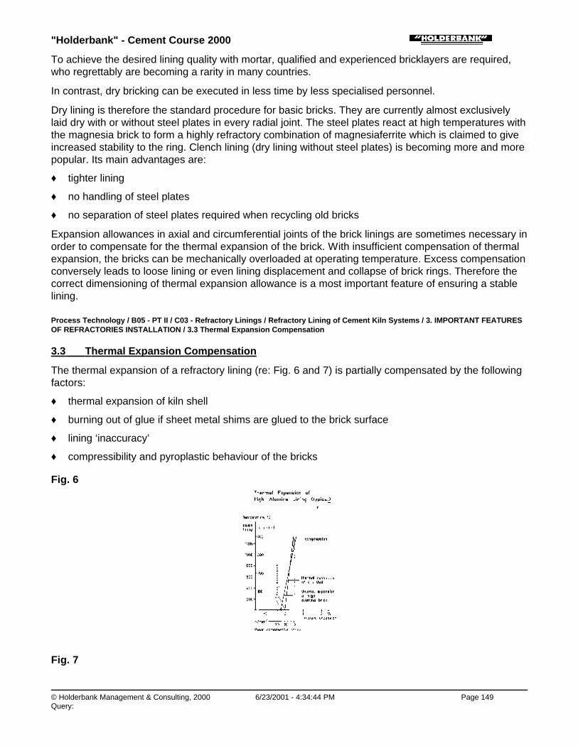
"Holderbank" - Cement Course 2000
© Holderbank Management & Consulting, 2000 6/23/2001 - 4:34:44 PM Page 149Query:
To achieve the desired lining quality with mortar, qualified and experienced bricklayers are required,who regrettably are becoming a rarity in many countries.
In contrast, dry bricking can be executed in less time by less specialised personnel.
Dry lining is therefore the standard procedure for basic bricks. They are currently almost exclusivelylaid dry with or without steel plates in every radial joint. The steel plates react at high temperatures withthe magnesia brick to form a highly refractory combination of magnesiaferrite which is claimed to giveincreased stability to the ring. Clench lining (dry lining without steel plates) is becoming more and morepopular. Its main advantages are:
♦ tighter lining
♦ no handling of steel plates
♦ no separation of steel plates required when recycling old bricks
Expansion allowances in axial and circumferential joints of the brick linings are sometimes necessary inorder to compensate for the thermal expansion of the brick. With insufficient compensation of thermalexpansion, the bricks can be mechanically overloaded at operating temperature. Excess compensationconversely leads to loose lining or even lining displacement and collapse of brick rings. Therefore thecorrect dimensioning of thermal expansion allowance is a most important feature of ensuring a stablelining.
Process Technology / B05 - PT II / C03 - Refractory Linings / Refractory Lining of Cement Kiln Systems / 3. IMPORTANT FEATURESOF REFRACTORIES INSTALLATION / 3.3 Thermal Expansion Compensation
3.3 Thermal Expansion Compensation
The thermal expansion of a refractory lining (re: Fig. 6 and 7) is partially compensated by the followingfactors:
♦ thermal expansion of kiln shell
♦ burning out of glue if sheet metal shims are glued to the brick surface
♦ lining ‘inaccuracy’
♦ compressibility and pyroplastic behaviour of the bricks
Fig. 6
Fig. 7
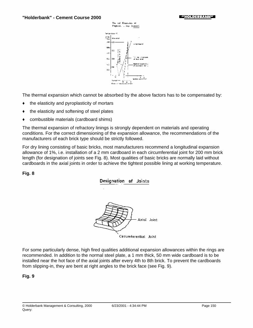
"Holderbank" - Cement Course 2000
© Holderbank Management & Consulting, 2000 6/23/2001 - 4:34:44 PM Page 150Query:
The thermal expansion which cannot be absorbed by the above factors has to be compensated by:
♦ the elasticity and pyroplasticity of mortars
♦ the elasticity and softening of steel plates
♦ combustible materials (cardboard shims)
The thermal expansion of refractory linings is strongly dependent on materials and operatingconditions. For the correct dimensioning of the expansion allowance, the recommendations of themanufacturers of each brick type should be strictly followed.
For dry lining consisting of basic bricks, most manufacturers recommend a longitudinal expansionallowance of 1%, i.e. installation of a 2 mm cardboard in each circumferential joint for 200 mm bricklength (for designation of joints see Fig. 8). Most qualities of basic bricks are normally laid withoutcardboards in the axial joints in order to achieve the tightest possible lining at working temperature.
Fig. 8
For some particularly dense, high fired qualities additional expansion allowances within the rings arerecommended. In addition to the normal steel plate, a 1 mm thick, 50 mm wide cardboard is to beinstalled near the hot face of the axial joints after every 4th to 8th brick. To prevent the cardboardsfrom slipping-in, they are bent at right angles to the brick face (see Fig. 9).
Fig. 9

"Holderbank" - Cement Course 2000
© Holderbank Management & Consulting, 2000 6/23/2001 - 4:34:44 PM Page 151Query:
If basic bricks are laid in mortar, additional expansion allowance in the axial joints is not necessary. Inthe circumferential joints an allowance of about 0.2% is made, i.e. a 2 mm cardboard is insertedbetween each fifth ring without mortar.
Alumina and fireclay bricks as a rule are installed without expansion allowance in the interest of astable lining. This is possible due to the lower thermal expansion of these bricks compared to the basicmaterials and due to good pyroplastic properties which permit accommodation of the stresses at hightemperatures.
Steel plates are not used with Alumina bricks, since steel and aluminium silicates form low meltingcompound at high temperature, which can lead to lining damage.
Process Technology / B05 - PT II / C03 - Refractory Linings / Refractory Lining of Cement Kiln Systems / 3. IMPORTANT FEATURESOF REFRACTORIES INSTALLATION / 3.4 Lining Methods
3.4 Lining Methods
The following factors have to be considered for kiln lining methods:
♦ safety
♦ tight installation of the bricks
♦ time required for lining
The methods applied can be generally classified as:
♦ rotating methods, i.e. the kiln has to be turned during lining
♦ formwork methods: the bricks are installed on a curved formwork without turning of the kiln
Process Technology / B05 - PT II / C03 - Refractory Linings / Refractory Lining of Cement Kiln Systems / 3. IMPORTANT FEATURESOF REFRACTORIES INSTALLATION / 3.4 Lining Methods / 3.4.1 Rotating Methods
3.4.1 Rotating Methods
With the rotating methods, kiln zones of 5 to 20 m length are lined at one time. Work is carried out onlyin the bottom of the kiln, which is rotated intermittently as the work of lining proceeds. The bricks mustbe fastened to the shell, e.g. by means of screw jacks or glues, as the ring of bricks is rotated into theoverhead position before being closed.
Process Technology / B05 - PT II / C03 - Refractory Linings / Refractory Lining of Cement Kiln Systems / 3. IMPORTANT FEATURESOF REFRACTORIES INSTALLATION / 3.4 Lining Methods / 3.4.1 Rotating Methods / 3.4.1.1 Screw-Jack Method (Fig. 10)
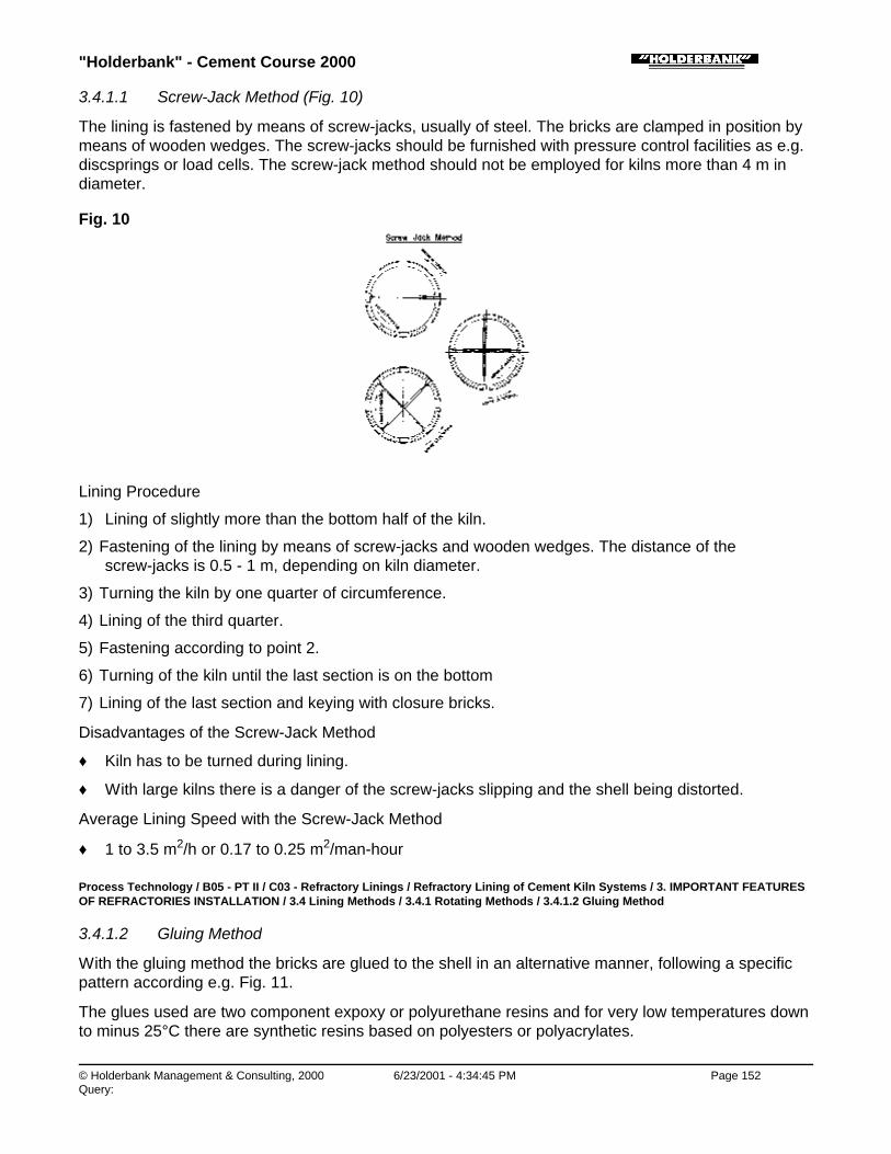
"Holderbank" - Cement Course 2000
© Holderbank Management & Consulting, 2000 6/23/2001 - 4:34:45 PM Page 152Query:
3.4.1.1 Screw-Jack Method (Fig. 10)
The lining is fastened by means of screw-jacks, usually of steel. The bricks are clamped in position bymeans of wooden wedges. The screw-jacks should be furnished with pressure control facilities as e.g.discsprings or load cells. The screw-jack method should not be employed for kilns more than 4 m indiameter.
Fig. 10
Lining Procedure
1) Lining of slightly more than the bottom half of the kiln.
2) Fastening of the lining by means of screw-jacks and wooden wedges. The distance of thescrew-jacks is 0.5 - 1 m, depending on kiln diameter.
3) Turning the kiln by one quarter of circumference.
4) Lining of the third quarter.
5) Fastening according to point 2.
6) Turning of the kiln until the last section is on the bottom
7) Lining of the last section and keying with closure bricks.
Disadvantages of the Screw-Jack Method
♦ Kiln has to be turned during lining.
♦ With large kilns there is a danger of the screw-jacks slipping and the shell being distorted.
Average Lining Speed with the Screw-Jack Method
♦ 1 to 3.5 m2/h or 0.17 to 0.25 m2/man-hour
Process Technology / B05 - PT II / C03 - Refractory Linings / Refractory Lining of Cement Kiln Systems / 3. IMPORTANT FEATURESOF REFRACTORIES INSTALLATION / 3.4 Lining Methods / 3.4.1 Rotating Methods / 3.4.1.2 Gluing Method
3.4.1.2 Gluing Method
With the gluing method the bricks are glued to the shell in an alternative manner, following a specificpattern according e.g. Fig. 11.
The glues used are two component expoxy or polyurethane resins and for very low temperatures downto minus 25°C there are synthetic resins based on polyesters or polyacrylates.

"Holderbank" - Cement Course 2000
© Holderbank Management & Consulting, 2000 6/23/2001 - 4:34:45 PM Page 153Query:
Fig. 11
The glues decompose after heating up above 200°C and lose their effect.
Lining procedure:
1) Cleaning of the shell down to the bright metal, if necessary with the aid of a grinder. The surfacemust be free from dust or grease.
2) Gluing of the first lining sector of approx. 5 brick rows.
3) Installation of the next sector without glue etc. The number of bricks between the glued sectorsdepend on brick weight, kiln diameter, glue properties, etc. Generally the brick and/or gluesuppliers specify the gluing pattern. As a rule approx. 20% of the bricks laid are glued. Glueconsumption amounts to approx. 0.4 to 0.8 kg/m2 of lined area or approx. 2 kg/m2 glued area.
Using the gluing method, the following points require careful consideration:
♦ The start to be glued must be fitted together before the adhesives start to set.
♦ The kiln should not be turned before the glue has developed sufficient strength.
♦ The glue must be carefully prepared according to the suppliers specifications, particularly withrespect to mixing ratio.
Disadvantages of the gluing method:
♦ Kiln has to be turned during lining.
♦ Tightening of the brick rings before keying is not possible, but only the bricks between two gluedsectors. Thus, lining mistakes are not easy to be localised.
♦ Safety risk if kiln is turned before glue has developed sufficient strength.
With the gluing method, average lining speeds of 3 to 7 m2/h or 0.4 to 1.2 m2/man-hour can beachieved.
Process Technology / B05 - PT II / C03 - Refractory Linings / Refractory Lining of Cement Kiln Systems / 3. IMPORTANT FEATURESOF REFRACTORIES INSTALLATION / 3.4 Lining Methods / 3.4.2 Formwork Methods
3.4.2 Formwork Methods
The formwork methods can nowadays be considered as the standard lining method. They are safe inoperation and permit very accurate installation of the bricks.
With the curved formwork methods, first the lower half shell of the kiln is lined without any particular
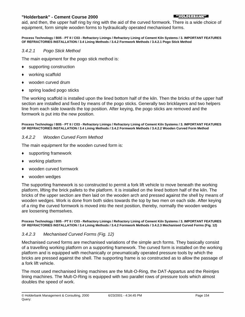
"Holderbank" - Cement Course 2000
© Holderbank Management & Consulting, 2000 6/23/2001 - 4:34:45 PM Page 154Query:
aid, and then, the upper half ring by ring with the aid of the curved formwork. There is a wide choice ofequipment, form simple wooden forms to hydraulically operated mechanised forms.
Process Technology / B05 - PT II / C03 - Refractory Linings / Refractory Lining of Cement Kiln Systems / 3. IMPORTANT FEATURESOF REFRACTORIES INSTALLATION / 3.4 Lining Methods / 3.4.2 Formwork Methods / 3.4.2.1 Pogo Stick Method
3.4.2.1 Pogo Stick Method
The main equipment for the pogo stick method is:
♦ supporting construction
♦ working scaffold
♦ wooden curved drum
♦ spring loaded pogo sticks
The working scaffold is installed upon the lined bottom half of the kiln. Then the bricks of the upper halfsection are installed and fixed by means of the pogo sticks. Generally two bricklayers and two helpersline from each side towards the top position. After keying, the pogo sticks are removed and theformwork is put into the new position.
Process Technology / B05 - PT II / C03 - Refractory Linings / Refractory Lining of Cement Kiln Systems / 3. IMPORTANT FEATURESOF REFRACTORIES INSTALLATION / 3.4 Lining Methods / 3.4.2 Formwork Methods / 3.4.2.2 Wooden Curved Form Method
3.4.2.2 Wooden Curved Form Method
The main equipment for the wooden curved form is:
♦ supporting framework
♦ working platform
♦ wooden curved formwork
♦ wooden wedges
The supporting framework is so constructed to permit a fork lift vehicle to move beneath the workingplatform, lifting the brick pallets to the platform. It is installed on the lined bottom half of the kiln. Thebricks of the upper section are then laid on the wooden arch and pressed against the shell by means ofwooden wedges. Work is done from both sides towards the top by two men on each side. After keyingof a ring the curved formwork is moved into the next position, thereby, normally the wooden wedgesare loosening themselves.
Process Technology / B05 - PT II / C03 - Refractory Linings / Refractory Lining of Cement Kiln Systems / 3. IMPORTANT FEATURESOF REFRACTORIES INSTALLATION / 3.4 Lining Methods / 3.4.2 Formwork Methods / 3.4.2.3 Mechanised Curved Forms (Fig. 12)
3.4.2.3 Mechanised Curved Forms (Fig. 12)
Mechanised curved forms are mechanised variations of the simple arch forms. They basically consistof a travelling working platform on a supporting framework. The curved form is installed on the workingplatform and is equipped with mechanically or pneumatically operated pressure tools by which thebricks are pressed against the shell. The supporting frame is so constructed as to allow the passage ofa fork lift vehicle.
The most used mechanised lining machines are the Mult-O-Ring, the DAT-Appartus and the Reintjeslining machines. The Mult-O-Ring is equipped with two parallel rows of pressure tools which almostdoubles the speed of work.
"Holderbank" - Cement Course 2000
© Holderbank Management & Consulting, 2000 6/23/2001 - 4:34:45 PM Page 155Query:
The lining procedure is similar to that with simple curved forms, except that the fastening of the bricksis mechanised.
With mechanised lining machines very high lining speeds of up to 6.5 m2/h or 0.5 m2/man-hour formortared linings and up to 9.5 m2/h or 0.75 m2/man-hour for dry lining can be achieved.
Fig. 12
Process Technology / B05 - PT II / C03 - Refractory Linings / Refractory Lining of Cement Kiln Systems / 3. IMPORTANT FEATURESOF REFRACTORIES INSTALLATION / 3.4 Lining Methods / 3.4.3 Lining with Unshaped Materials
3.4.3 Lining with Unshaped Materials
Unshaped refractory materials can be installed by casting, gunning or ramming. The installed massesare fixed by metallic anchors which provide a good lining stability even in cases of local damages orspallings. Usually V-type anchors, generally delivered by the refractory supplier, are welded in a crosspattern on the shell. About 15 to 25 anchors per m2 are required, depending on lining thickness.
Process Technology / B05 - PT II / C03 - Refractory Linings / Refractory Lining of Cement Kiln Systems / 3. IMPORTANT FEATURESOF REFRACTORIES INSTALLATION / 3.4 Lining Methods / 3.4.3 Lining with Unshaped Materials / 3.4.3.1 Castables
3.4.3.1 Castables
Castables or refractory concrete contain a hydraulic setting agent (high alumina cement). They areinstalled generally in suitable formworks, e.g. by the rotocasting method (Fig. 13) and compacted byvibrating. In order to avoid spalling due to quick water evaporation during heating up, it can beadvisable to perforate the surface by pushing steel wires of 5 mm thickness into the freshly placedcastable at a distance of approx. 5 cm. The steel wires are to be removed after hardening of thecastables. During the hardening period just after installation of the castable, its surface should beprotected against too quick evaporation of water by means of wet cloths or water spray.
Fig. 13

"Holderbank" - Cement Course 2000
© Holderbank Management & Consulting, 2000 6/23/2001 - 4:34:46 PM Page 156Query:
Process Technology / B05 - PT II / C03 - Refractory Linings / Refractory Lining of Cement Kiln Systems / 3. IMPORTANT FEATURESOF REFRACTORIES INSTALLATION / 3.4 Lining Methods / 3.4.3 Lining with Unshaped Materials / 3.4.3.2 Guniting Materials
3.4.3.2 Guniting Materials
Guniting materials are supplied either with chemically or with hydraulically setting bonding agents. Thematerials are placed pneumatically, passing through a hose to a mixing nozzle where water isintroduced (Fig. 14).
Fig. 14
Guniting should always be done by specialised personnel, since quality of the lining as well as amountof losses in rebounding is highly depending on the ability of the operator. Depending on shape andposition of the working surface losses in rebound amount from 10 to 50%.
During the hardening period, the gunned surface must be protected against water evaporation similarto castables. Also perforation of the surface by means of steel wires can be advisable.
Process Technology / B05 - PT II / C03 - Refractory Linings / Refractory Lining of Cement Kiln Systems / 3. IMPORTANT FEATURESOF REFRACTORIES INSTALLATION / 3.4 Lining Methods / 3.4.3 Lining with Unshaped Materials / 3.4.3.3 Ramming Material
3.4.3.3 Ramming Material
Ramming materials are plastic or granular materials, generally chemically, seldom hydraulicallybonded.
Due to the low water content, rammed refractories generally have low porosity, high volume stabilityand strength and good resistance against chemical attack.
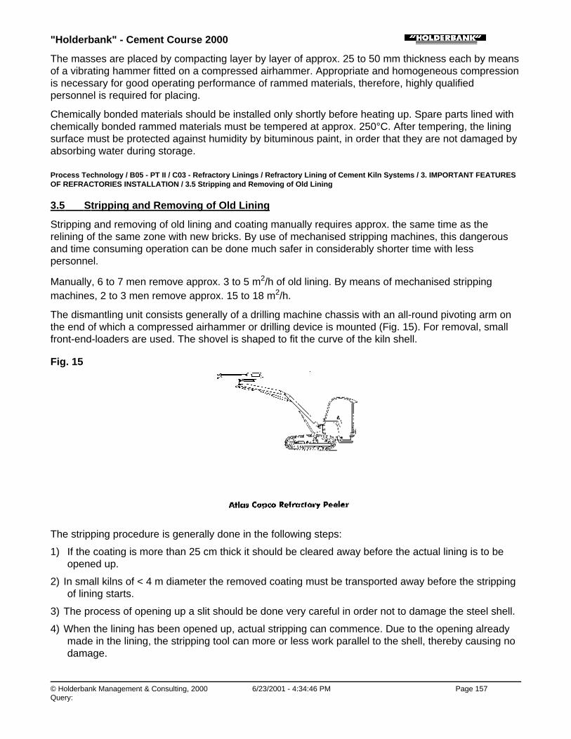
"Holderbank" - Cement Course 2000
© Holderbank Management & Consulting, 2000 6/23/2001 - 4:34:46 PM Page 157Query:
The masses are placed by compacting layer by layer of approx. 25 to 50 mm thickness each by meansof a vibrating hammer fitted on a compressed airhammer. Appropriate and homogeneous compressionis necessary for good operating performance of rammed materials, therefore, highly qualifiedpersonnel is required for placing.
Chemically bonded materials should be installed only shortly before heating up. Spare parts lined withchemically bonded rammed materials must be tempered at approx. 250°C. After tempering, the liningsurface must be protected against humidity by bituminous paint, in order that they are not damaged byabsorbing water during storage.
Process Technology / B05 - PT II / C03 - Refractory Linings / Refractory Lining of Cement Kiln Systems / 3. IMPORTANT FEATURESOF REFRACTORIES INSTALLATION / 3.5 Stripping and Removing of Old Lining
3.5 Stripping and Removing of Old Lining
Stripping and removing of old lining and coating manually requires approx. the same time as therelining of the same zone with new bricks. By use of mechanised stripping machines, this dangerousand time consuming operation can be done much safer in considerably shorter time with lesspersonnel.
Manually, 6 to 7 men remove approx. 3 to 5 m2/h of old lining. By means of mechanised strippingmachines, 2 to 3 men remove approx. 15 to 18 m2/h.
The dismantling unit consists generally of a drilling machine chassis with an all-round pivoting arm onthe end of which a compressed airhammer or drilling device is mounted (Fig. 15). For removal, smallfront-end-loaders are used. The shovel is shaped to fit the curve of the kiln shell.
Fig. 15
The stripping procedure is generally done in the following steps:
1) If the coating is more than 25 cm thick it should be cleared away before the actual lining is to beopened up.
2) In small kilns of < 4 m diameter the removed coating must be transported away before the strippingof lining starts.
3) The process of opening up a slit should be done very careful in order not to damage the steel shell.
4) When the lining has been opened up, actual stripping can commence. Due to the opening alreadymade in the lining, the stripping tool can more or less work parallel to the shell, thereby causing nodamage.
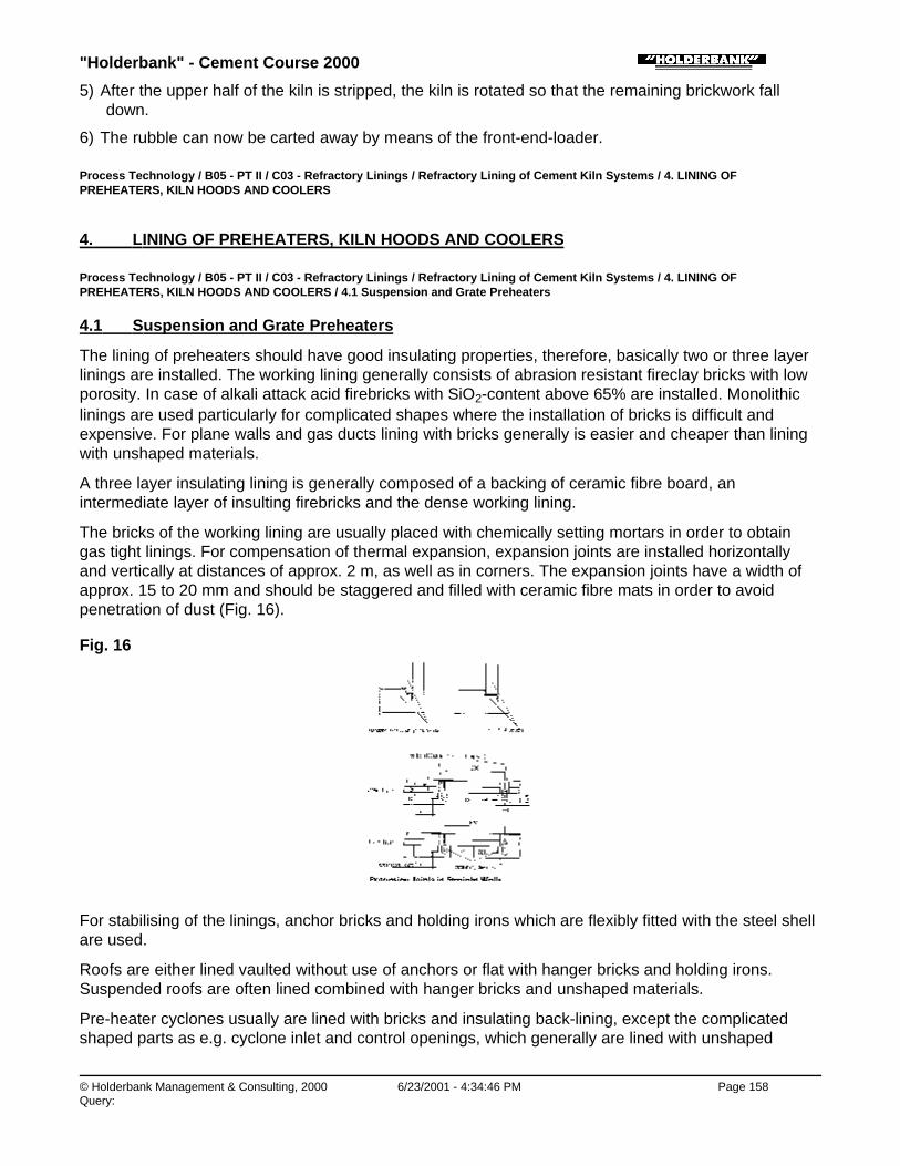
"Holderbank" - Cement Course 2000
© Holderbank Management & Consulting, 2000 6/23/2001 - 4:34:46 PM Page 158Query:
5) After the upper half of the kiln is stripped, the kiln is rotated so that the remaining brickwork falldown.
6) The rubble can now be carted away by means of the front-end-loader.
Process Technology / B05 - PT II / C03 - Refractory Linings / Refractory Lining of Cement Kiln Systems / 4. LINING OFPREHEATERS, KILN HOODS AND COOLERS
4. LINING OF PREHEATERS, KILN HOODS AND COOLERS
Process Technology / B05 - PT II / C03 - Refractory Linings / Refractory Lining of Cement Kiln Systems / 4. LINING OFPREHEATERS, KILN HOODS AND COOLERS / 4.1 Suspension and Grate Preheaters
4.1 Suspension and Grate Preheaters
The lining of preheaters should have good insulating properties, therefore, basically two or three layerlinings are installed. The working lining generally consists of abrasion resistant fireclay bricks with lowporosity. In case of alkali attack acid firebricks with SiO2-content above 65% are installed. Monolithiclinings are used particularly for complicated shapes where the installation of bricks is difficult andexpensive. For plane walls and gas ducts lining with bricks generally is easier and cheaper than liningwith unshaped materials.
A three layer insulating lining is generally composed of a backing of ceramic fibre board, anintermediate layer of insulting firebricks and the dense working lining.
The bricks of the working lining are usually placed with chemically setting mortars in order to obtaingas tight linings. For compensation of thermal expansion, expansion joints are installed horizontallyand vertically at distances of approx. 2 m, as well as in corners. The expansion joints have a width ofapprox. 15 to 20 mm and should be staggered and filled with ceramic fibre mats in order to avoidpenetration of dust (Fig. 16).
Fig. 16
For stabilising of the linings, anchor bricks and holding irons which are flexibly fitted with the steel shellare used.
Roofs are either lined vaulted without use of anchors or flat with hanger bricks and holding irons.Suspended roofs are often lined combined with hanger bricks and unshaped materials.
Pre-heater cyclones usually are lined with bricks and insulating back-lining, except the complicatedshaped parts as e.g. cyclone inlet and control openings, which generally are lined with unshaped
"Holderbank" - Cement Course 2000
© Holderbank Management & Consulting, 2000 6/23/2001 - 4:34:46 PM Page 159Query:
materials.
Meal chutes should be lined with highly abrasion resistant materials. Usually dense castables withmetallic anchors or prefabricated materials are installed.
Process Technology / B05 - PT II / C03 - Refractory Linings / Refractory Lining of Cement Kiln Systems / 4. LINING OFPREHEATERS, KILN HOODS AND COOLERS / 4.2 Kiln Hood
4.2 Kiln Hood
For kilns equipped with planetary coolers, refractory lining in the hood section is limited to the hinged orotherwise movable kiln door with openings for burners, measuring instruments and observation. Themost frequently used lining material is dense castable fireclay together with insulating backing.
The lining of the kiln hood of kilns equipped with grate or rotary coolers generally consists of a denseworking face and an insulating backing. The working lining must possess high thermal shockresistance and abrasion resistance. In the upper region, where the lining is exposed to direct flameradiation, alumina refractories with Al2O3-contents of up to 70% are used. The lower region is usuallylined with dense fireclay. As insulating linings conventional insulating bricks as well as insulatinggunning mixes or castables are used.
Process Technology / B05 - PT II / C03 - Refractory Linings / Refractory Lining of Cement Kiln Systems / 4. LINING OFPREHEATERS, KILN HOODS AND COOLERS / 4.3 Clinker Coolers
4.3 Clinker Coolers
(Fig. 17)
Approximately 15 to 35% of the length of planetary coolers is refractory lined. This lining should have ahigh resistivity against thermal shock and abrasion. For the cam lining section dense, high aluminabricks with high hardness and strength are used. The inlet bends are usually lined with dense highalumina, or even pure Corundum castables. For simpler geometric shapes conventional bricks ofsuitable quality can also be used.
In rotary coolers, about 50% of the tube length is lined with refractory materials. In the inlet zones,similar as in planetary coolers, refractories of high strength fireclay are normally installed.
The refractory lining of grate coolers, with the exception of the areas immediately above the grate(where direct contact with clinker occurs), is exposed to far a lower extent to thermal fluctuations andabrasion. Normally a two or three layer refractory wall and roof is installed, consisting of an insulatingrear and a dense fireclay working lining.
The wear zones immediately above the grate consist of particularly abrasion resistant bricks orcastables.
Fig. 17

"Holderbank" - Cement Course 2000
© Holderbank Management & Consulting, 2000 6/23/2001 - 4:34:47 PM Page 160Query:
Process Technology / B05 - PT II / C03 - Refractory Linings / Refractory Lining of Cement Kiln Systems / 5. OPERATIONAL ASPECTSREGARDING KILN LININGS
5. OPERATIONAL ASPECTS REGARDING KILN LININGS
Process Technology / B05 - PT II / C03 - Refractory Linings / Refractory Lining of Cement Kiln Systems / 5. OPERATIONAL ASPECTSREGARDING KILN LININGS / 5.1 Heat-Up of Rotary Kiln Systems
5.1 Heat-Up of Rotary Kiln Systems
The heating-up program, which mainly determines the amount of kiln temperature increase per unit oftime and the timing of the raw material feed, must consider a number of factors such as type ofrefractory material, design of kiln system, mechanical systems etc.. The optimum heating programconstitutes a compromise which best satisfies the various requirements.
Optimum Heating Period:
♦ Refractory Materials
• Material quality
• Type of bond
• Installation method
♦ Riding Ring
• Riding ring clearance
• Riding ring dimensions
• Monitoring capabilities
♦ Exhaust Gas Flow
• Temperature profile in kiln
• Permissible temperatures
• Environmental regulations
Process Technology / B05 - PT II / C03 - Refractory Linings / Refractory Lining of Cement Kiln Systems / 5. OPERATIONAL ASPECTSREGARDING KILN LININGS / 5.1 Heat-Up of Rotary Kiln Systems / 5.1.1 Requirements from a Refractory Materials Viewpoint
5.1.1 Requirements from a Refractory Materials Viewpoint
The minimum heating-up duration from the refractory materials viewpoint is given by the type of special

"Holderbank" - Cement Course 2000
© Holderbank Management & Consulting, 2000 6/23/2001 - 4:34:47 PM Page 161Query:
bricks and castables installed. Generally, the heating-up specifications of the suppliers must berespected. The minimum heating-up time is indicated by that material which requires the longestheating-up period because the minimum heating-up time can generally be extended but not shortenedwithout causing damage. Exception: basic brick linings tend to hydrate when kept at temperaturesbetween 100 and 450°C for several days.
Generally, the heating-up time is influenced by the following materials:
♦ Castable refractories with hydraulic bonding (Fig. 18)
• Approx. 24 hrs setting time at room temperature
• Approx. 24 hrs drying time at 100 to 200°C
• Heating-up at the rate of 25°C/h up to 500°C (expels crystal water)
• In subsequent heating-up cycles, operational temperatures may be reached more rapidly. Thespeed of reaching operational temperatures might be limited by other factors as e.g. the tyresituation.
♦ Castable refractories with chemical bonding
• Approx. 8 to 16 hrs drying time at 100 to 200°C
• Heating-up at the rate of 20 to 30°C/h up to 700°C (until chemical bonding is completed)
• In subsequent heating-up cycles, operational temperatures may be reached more rapidly, asexplained above.
♦ Untempered, phosphate bonded bricks
• Heating-up to 700°C (termination of chemical bonding) at the rate of 30°C/h
• In subsequent heating-up cycles, operational temperature may be reached more rapidly, asexplained above
♦ Jointing materials (mortars)
• Theoretically the same rules would apply as for casting mixes; however, the situation is notcritical because of the limited joint thickness.
Fig. 18
Based on the above listed criteria, most suppliers of refractory materials recommend for the start-up ofnew kilns, and after major overhauls with monolithic linings, a maximum heating-up rate of approx.25°C/h, in the sintering zone, up to a sintering zone temperature of 900°C. (Whereby a previous dryingof heat exchanger systems and monolithically lined kiln zones is assumed.)
After reaching 900°C, heating -up can continue at the rate of 50°C/h up to working temperature.

"Holderbank" - Cement Course 2000
© Holderbank Management & Consulting, 2000 6/23/2001 - 4:34:47 PM Page 162Query:
After minor repairs and after shut-downs not caused by defective lining, refractory materials suppliersgenerally recommend a heating-up rate in the sintering zone of 50°C/h.
An example of heating-up scheme is shown in Fig. 19.
Fig. 19
Faster heat-up times are sometimes reported. Some Japanese suppliers heat-up new kilns in 5 to 8hours without any damage to lining and kiln system. Such procedures can, however, not berecommended in general, i.e. without considering the entire situation of lining quality and mechanicaldetails of kiln design. Since expansion joints are dimensioned to produce optimum lining stability understandard working conditions, rapid heat build-up may cause spalling due to excessive mechanicalstress of the brick surface because the lining face heats-up more rapidly than the kiln shell.
Process Technology / B05 - PT II / C03 - Refractory Linings / Refractory Lining of Cement Kiln Systems / 5. OPERATIONAL ASPECTSREGARDING KILN LININGS / 5.1 Heat-Up of Rotary Kiln Systems / 5.1.2 Riding Rings (Floating Type)
5.1.2 Riding Rings (Floating Type)
From a riding ring point of view, the minimum heating-up period is determined by the time required tostabilise the temperature difference between the kiln shell and riding rings. The shell will heat-up morerapidly than the tyre. The critical temperature difference results in a constriction of the kiln shell, whichwill cause permanent deformation if the yield strength of the kiln shell material is exceeded. This in turnwill cause excessive play in the riding ring after the normal working temperature is regained, as well asincreased ovality of the kiln shell, a factor which may contribute to excessive refractory lining wear.
As a general rule, the riding ring creep, i.e. the relative motion between riding ring and kiln shell shouldbe monitored at regular intervals or, even better continuously, at least during the heat-up cycle. Variousmeasures may be taken to protect the riding ring section from overheating.
With imminent danger of seizure, the heating-up process should be slowed down or interrupted until ameasurable amount of relative movement is again present. For this reason, the tyre creep maybecome the limiting factor in determining the heating-up rate.
Process Technology / B05 - PT II / C03 - Refractory Linings / Refractory Lining of Cement Kiln Systems / 5. OPERATIONAL ASPECTSREGARDING KILN LININGS / 5.1 Heat-Up of Rotary Kiln Systems / 5.1.3 Exhaust Gas Control
5.1.3 Exhaust Gas Control
Temperature Gradient in Kiln System
Already during the heating-up process a temperature gradient is sought which at the start of the raw

"Holderbank" - Cement Course 2000
© Holderbank Management & Consulting, 2000 6/23/2001 - 4:34:47 PM Page 163Query:
meal feeding to the kiln is equivalent or similar to the temperature gradient prevailing under normaloperating conditions. This condition can be approximately reached under ideal heat-up conditions andwith correct flame patterns, because in a dynamic heating process, the cold kiln system is heatedalong the flow direction of the exit gas while the exit gases are simultaneously cooled. With optimumfuel addition, this procedure is ideally continued with material feed by preheating the raw meal in thecounterflow. In practice, however, such a smooth transition is not possible because the amount ofmaterial fed can, for mechanical reasons, not be reduced to indefinitely small amounts and becausethe heat transfer to the meal is governed by endothermic and exothermic reactions.
For correct temperature gradients, fuel combustion at lowest possible amount of excess air is anecessity. In this manner, the temperature gradient between gas and lining and the dwell time of thegases within the kiln system will result in optimum absorption of the available heat by the refractorylining.
Process Technology / B05 - PT II / C03 - Refractory Linings / Refractory Lining of Cement Kiln Systems / 5. OPERATIONAL ASPECTSREGARDING KILN LININGS / 5.1 Heat-Up of Rotary Kiln Systems / 5.1.4 Shut-down of Kiln Systems
5.1.4 Shut-down of Kiln Systems
The procedure for shutting down a kiln depends mainly on whether it is a planned shut-down or anemergency stop due to a breakdown.
To protect the lining, the cooling rate should, if possible, not exceed the maximum permissible heatingrate, i.e. approx. 50°C/h measured in the sintering zone. Excessively rapid cooling may cause damageto the refractory lining due to thermal shock.
After stopping raw meal and fuel feed, the exhaust gas damper is closed and the exhaust gas fan isstopped. Closing the exhaust gas path prevents gas circulation within the kiln and the temperatureprofile is more or less maintained. The cooling rate of 50°C/h will initially be reached by radiation alone.Only after a dull red heat is reached in the sintering zone cooling should continue with a light draft untilthe end of the cooling phase is reached.
Process Technology / B05 - PT II / C03 - Refractory Linings / Refractory Lining of Cement Kiln Systems / 5. OPERATIONAL ASPECTSREGARDING KILN LININGS / 5.2 Kiln Shell Deformation
5.2 Kiln Shell Deformation
The refractory life and coating stability in the area of kiln tyres is significantly influenced by kilndeformation. As a result of changes in the kiln shell radius, there is a movement between the brickswhich results in local surface pressure, leading to rapid wear and possibly total lining collapse.
The measurement of kiln shell deformation can be made during kiln operation with the aid of the‘Holderbank’ Shell-Test Gauge.
The measuring principle is illustrated in Fig. 20.
Fig. 20

"Holderbank" - Cement Course 2000
© Holderbank Management & Consulting, 2000 6/23/2001 - 4:34:48 PM Page 164Query:
The yoke (A) of the Shell-test gauge covers a circular section with a chord of length of 1 m and heighth.
During kiln rotation the chord height h changes with the continuously changing curvature radius r of thekiln shell.
This change is transferred via a plunger (D) and recorder (C) to produce a polar diagram (shell-testdiagram).
The closed line drawn on the diagram represents a geometrically similar figure to the deformed kilnshell cross section.
The subsequent calculation is based on determining the difference between the longest and theshortest radius of the shell-test diagram after which the ovality is calculated according to the method ofG. Rosenblad.
The mechanical condition of kiln shell and kiln tyres with respect to allowable ovality should beregularly checked.
For kiln with loose tyre design, an indication on the mechanical condition of the tyre section can begained by continuous measurement of the difference in rotational speed of the kiln tyre and kiln shell.This method permits continuous indication/recording in the control room (Fig. 21).
Fig. 21
Process Technology / B05 - PT II / C03 - Refractory Linings / Refractory Lining of Cement Kiln Systems / 5. OPERATIONAL ASPECTSREGARDING KILN LININGS / 5.3 Fluctuating Process Parameters
5.3 Fluctuating Process Parameters
"Holderbank" - Cement Course 2000
© Holderbank Management & Consulting, 2000 6/23/2001 - 4:34:48 PM Page 165Query:
Unstable burning conditions of cement kilns belong still to the most frequent reasons of refractory liningfailures. All types of used sintering zone refractories show structural changes between hot and coldface, infiltrated circulating elements of faded brick sections by overheating, do not immediately result inrefractory failures. However, if kiln operating conditions change, followed by changed thermal profile orchanged coating conditions, the bricks break off in large lumps since, due to its altered structure, theirmechanical characteristics have deteriorated.
Unstable burning conditions can be caused by
♦ Unstable kiln feed due to insufficient material flow control
♦ Fluctuating kiln feed composition due to insufficient homogenising of raw material
♦ Fluctuating flame length due to insufficient fuel flow control or fluctuating fuel quality
♦ Frequent kiln shut-down due to maintenance problems of auxiliary equipment, power failures orrefractory failures.
Without going into details it is evident, that these points need to be carefully watched and, if required,improved, in order to establish the conditions which make the improvements in the field of refractorylining selection, installation and operation effective.
Process Technology / B05 - PT II / C03 - Refractory Linings / Refractory Lining of Cement Kiln Systems / 6. CONCLUSIONS
6. CONCLUSIONS
Improvement of refractory lining lifetime is not a matter of one single criterion. There exist several fieldsof influence which often are jointly responsible for the results obtained.
The following list contains suggestions concerning the most important and general consideration forachieving improvement in lining life.
Since the major refractory problems occur in the sintering and transition zone, most of theconsiderations will concentrate on these kiln areas.
Most important factors:
1) Optimisation of kiln feed (qualitatively and quantitatively)∗ by selective quarrying procedures∗ by selection of optimum raw material composition∗ by appropriate homogenising of raw materials∗ by improvement of kiln feeding equipment
2) Optimisation of flame shape and length∗ by evaluation of the influence of adjustable flames∗ by the most constant burning possible with the optimally established flame shape
3) Improvement of mechanical condition of kiln shell in the tyre area∗ by adjustment to minimum possible tyre clearance∗ by continuously monitoring tyre creep∗ by cooling of kiln tyre areas when danger of seizure exists
4) Optimisation of brick quality in the sintering zone∗ by methodical investigations (trials) with alternative brick qualities
5) Thermal load reduction∗ by introduction of secondary firing (if applicable)
"Holderbank" - Cement Course 2000
© Holderbank Management & Consulting, 2000 6/23/2001 - 4:34:48 PM Page 166Query:
6) Reduction of the number of kiln shut-downs∗ by improving the mechanical and electrical reliability of the system∗ by installation of emergency power supply
7) Optimisation of the bricking process∗ by refining existing or selecting better methods∗ by improvement of working conditions or methods∗ by introducing clear instructions, control (bonus systems)∗ by optimised bricking policy
8) Prevention of rapid heating or cooling∗ by observing the important factors on kiln light-up∗ by prevention of rapid cooling on shut-down
This list is not claimed to be complete and some of the suggestions might not be realisable for aspecific case on hand. As a check-list, however, it allows the identification of points of weakness andthe establishment of further procedures in order to be able to define the actual problem and finally tosolve it as effectively as possible.
Process Technology / B05 - PT II / C03 - Refractory Linings / Refractory Lining of Cement Kiln Systems / 7. TEST QUESTIONS
7. TEST QUESTIONS
1) Please make a sketch of the various zones of a suspension pre-heater-, Lepol -and a long wet kilnand indicate what type of refractories are used in each zone.
2) Explain the different methods you know of refractory brick installation in a rotary kiln (sketches).
3) Where are the unshaped refractories mainly used in cement kiln system?
4) What are the main features of brick joints (jointing materials) for rotary kiln linings in the case ofalumina and basic bricks, considering dry and mortar lining?
5) Establishment of a heating-up program for cement kilns is mainly based on considerations regardingthree main factors. What are these considerations?

"Holderbank" - Cement Course 2000
© Holderbank Management & Consulting, 2000 6/23/2001 - 4:34:50 PM Page 167Query:
Process Technology / B05 - PT II / C04 - Firing Systems
C04 - Firing Systems

"Holderbank" - Cement Course 2000
© Holderbank Management & Consulting, 2000 6/23/2001 - 4:34:50 PM Page 168Query:
Process Technology / B05 - PT II / C04 - Firing Systems / Firing Systems: Handling and Preparation of Noble Fuels
Firing Systems: Handling and Preparation of Noble Fuels D. PaulingPT 98/14353/E
1. Introduction
2. coal Firing Systems
2.1 Classification of Coal Firing Systems
2.2 Quality of Coal Preparation
2.3 Pulverized Coal Dosing
2.3.1 Feed Bins for Pulverized Coal
2.3.2 Weighing and dosing of pulverized coal
2.3.3 Most Common Pulverized Coal Dosing Systems
2.4 Pneumatic Transport of Pulverized Coal to the Burner
3. Oil firing systems
3.1 Fuel Oil Transfer from Delivery Point to the Storage Tank
3.2 Fuel Oil Storage
3.3 Fuel Oil Preparation
3.3.1 Heating with Steam
3.3.2 Heating with Thermal Oil:
3.3.3 Heating with Electricity
3.3.4 Heating with Flame Radiation
3.4 Quality of Fuel Oil Preparation
3.5 Control Loops in the Fuel Oil Circuit
4. Natural gas firing systems
4.1 Natural Gas Preparation
4.2 Safety Precautions
4.2.1 Flexible Hoses Bursting
4.2.2 Leak Tests
4.2.3 Explosions in the Kiln
5. list of references

"Holderbank" - Cement Course 2000
© Holderbank Management & Consulting, 2000 6/23/2001 - 4:34:50 PM Page 169Query:
Process Technology / B05 - PT II / C04 - Firing Systems / Firing Systems: Handling and Preparation of Noble Fuels / 1.INTRODUCTION
1. INTRODUCTION
Noble fuels are coal, fuel oil and natural gas. Handling and preparation of those fuels has to fulfillcertain requirements in order to produce similar combustion conditions for those different fuels andavoid incomplete combustion, e.g. CO at kiln inlet or local reducing conditions due to combustion offuel particles in the clinker bed.
For coal firing the main types of firing systems are described (direct, semi-direct and indirect firing). Forpulverized coal dosing and transport to the burner the important design criterias are outlined. Therequired coal dust qualities for a good combustion in the cement kiln are described.
For fuel oil firing, preparation and heating systems are outlined. The required fuel oil qualities(pressure, viscosity and temperature) are given.
For natural gas firing, preparation and safety precautions are described.
Burners, injection characteristics and flames are not subject of this paper (see paper: "Burners andFlames").
Process Technology / B05 - PT II / C04 - Firing Systems / Firing Systems: Handling and Preparation of Noble Fuels / 2. COALFIRING SYSTEMS
2. COAL FIRING SYSTEMS
Before the coal is fired, it has to be prepared according to the required fineness. The coal has to bedried to 0.5 - 1.5 % residual moisture content, since moisture in the coal means loss of calorific value,as the water has to be evaporated and heated up to flame temperature. Coal drying is donesimultaneously with the grinding.
Process Technology / B05 - PT II / C04 - Firing Systems / Firing Systems: Handling and Preparation of Noble Fuels / 2. COALFIRING SYSTEMS / 2.1 Classification of Coal Firing Systems
2.1 Classification of Coal Firing Systems
With reference to gas and material flow, the coal firing systems can be classified into four main groupswhich in total sum up to six individual systems (Fig. 1).
Figure 1: Classification of Coal Firing Systems

"Holderbank" - Cement Course 2000
© Holderbank Management & Consulting, 2000 6/23/2001 - 4:34:50 PM Page 170Query:
System 1 - Direct firing
Represents the most simple case. The coal is ground in the mill, dried and blown into the kiln togetherwith the drying gases.
System 2 - Direct firing
Basically describes the same solution with the exception of the mill working under positive pressure.This solution is generally applied to protect the fan when processing abrasive coal.
System 3 - Direct firing
In system 3, the fan is protected by separating the pulverized coal in a cyclone and feeding it after thefan into the primary air stream.
System 3a - Direct firing with recirculation
Same as system 3, but with recirculating drying air. This arrangement allows reduced primary air ratios.
System 4 - Semi-direct firing
Has little technical significance since the solution with intermediate storage of coal would generally begiven preference.
System 5a - Semi-indirect firing
With system 5a, the kiln can be operated independently of short mill shut downs since the pulverizedcoal is stored in an intermediary storage bin. The exhaust air from the mill enters the kiln as primaryair.
System 5b - Semi-indirect firing with recirculation
Same as system 5a, but with recirculating drying air. This arrangement allows reduced primary airratios.
System 6 - Indirect firing
In system 6, the grinding installation is completely separated from the kiln. The pulverized coal isstored in an intermediary storage bin and the exhaust air from the mill is released through a filter intothe atmosphere. By this way, the kiln operation is completely independent from the combined dryingand grinding operation.
Major Advantages / Disadvantages of the Different Coal Firing Systems:
Direct firing Semi-indirect firing Indirect firing
Conventional modified Conventional Modified
System 1 and 2 System 3a System 5a System 5b System 6
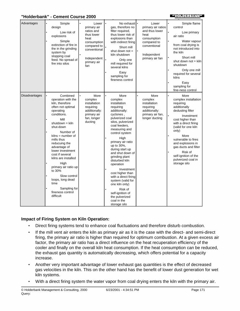
"Holderbank" - Cement Course 2000
© Holderbank Management & Consulting, 2000 6/23/2001 - 4:34:51 PM Page 171Query:
System 1 and 2 System 3a System 5a System 5b System 6Advantages • Simple
design
• Low risk ofexplosions
• Simpleextinction of fire inthe in the grindingsystem bystopping coalfeed. No spread offire into silos
• Lowerprimary airratios andthus lowerheatconsumptioncompared toconventional
• Independentprimary airfan
• No exhaustgas, therefore nofilter required,thus lower risk ofexplosions thanwith indirect firing
• Short millshut down not =kiln shutdown
• Only onemill required forseveral kilns
• Easysampling forfineness control
• Lowerprimary air ratiosand thus lowerheatconsumptioncompared toconventional
• Independentprimary air fan
• Simple flamecontrol
• Low primaryair ratio
• Water vapourfrom coal drying isnot introduced intothe kiln
• Short millshut down not = kilnshutdown
• Only one millrequired for severalkilns
• Easysampling forfine-ness control
Disadvantages • Combinedoperation with thekiln, thereforeoften not optimaloperatingconditions.
• Millshutdown = kilnshut-down
• Number ofkilns = number ofmills thusreducuing theadvantage oflower investmentcost if severalkilns are installed
• Highprimary air ratio upto 30%
• Slow controlloops, long deadtime
• Sampling forfineness controldifficult
• Morecomplexinstallationrequiringadditionally:primary airfan, longerducting
• Morecomplexinstallationrequiringadditionally:cyclones ,pulverized coalsilos, pulverizedcoal feeders,measuring andcontrol system
• Highprimary air ratioup to 30%,during start upand shut down ofgrinding plantdisturbed kilnoperation
• Investmentcost higher thanwith a direct firingsystem (valid forone kiln only)
• Risk ofself-ignition ofthe pulverizedcoal in thestorage silo
• Morecomplexinstallationrequiringadditionally:primary air fan,longer ducting
• Morecomplex installationrequiringadditionallydedusting filter
• Investmentcost higher thanwith a direct firing(valid for one kilnonly)
• Morevulnerable to firesand explosions ingas ducts and filter
• Risk ofself-ignition of thepulverized coal instorage silo
Impact of Firing System on Kiln Operation:
• Direct firing systems tend to enhance coal fluctuations and therefore disturb combustion.
• If the mill vent air enters the kiln as primary air as it is the case with the direct- and semi-directfiring, the primary air ratio is higher than required for optimum combustion. At a given excess airfactor, the primary air ratio has a direct influence on the heat recuperation efficiency of thecooler and finally on the overall kiln heat consumption. If the heat consumption can be reduced,the exhaust gas quantity is automatically decreasing, which offers potential for a capacityincrease.
• Another very important advantage of lower exhaust gas quantities is the effect of decreasedgas velocities in the kiln. This on the other hand has the benefit of lower dust generation for wetkiln systems.
• With a direct firing system the water vapor from coal drying enters the kiln with the primary air.

"Holderbank" - Cement Course 2000
© Holderbank Management & Consulting, 2000 6/23/2001 - 4:34:51 PM Page 172Query:
The water vapor has no direct influence on the combustion process, but increases the kilnexhaust gas quantity accordingly. A water content of 15% in the coal increases the exhaust gasquantity of a dry process kiln by approx. 1.5% and of a wet process kiln by 1.2 %.
• At the same time, the flame stability may decrease as a result of dilution of the primary air.
• Flame shape is strongly influenced by the type of firing system. An indirect system will not onlysupport a more stable flame, but also a shorter one, which results in smaller, more evendistributed alite crystals with higher reactivity. Benefits are better quality of the clinker and alower energy demand for the cement grinding.
• For new projects direct firing will not be selected anymore because of the above mentioneddisadvantages. Today indirect firing systems are "State of Technology". Conversion projectsfrom direct to indirect firing for existing installations can not always be financially justified on thebasis of reduced thermal energy consumption. In countries with low coal prices, pay back timesof several years must be expected. However, what can make a conversion project interesting,are the positive effects on kiln operation and thus product quality.
Process Technology / B05 - PT II / C04 - Firing Systems / Firing Systems: Handling and Preparation of Noble Fuels / 2. COALFIRING SYSTEMS / 2.2 Quality of Coal Preparation
2.2 Quality of Coal Preparation
Inadequate coal preparation (fineness) can result in both burn-out problems (CO formation) and thepresence of fuel in the material bed (increased volatility of sulfur).
The combustion time of coal depends on the content of volatile elements.
Fig. 2 shows the principal requirements for coal fineness in function of the volatile content.
Figure 2: The Grinding Fineness of Coal in Function of its Volatile Content
The aim is to comply with the following simple rule as an upper limit:
• Residue on the 90 µm sieve < ½ (% volatile components)
• Residue on the 200 µm sieve < 2%
For low volatile and difficult to burn coal types such as petrol coke and anthracite, the above mentionedrule has to be tightened:
• Residue on 90 µm sieve for petrol coke and anthracite < 5 %
• Residue on 200 µm sieve for petrol coke and anthracite < 1 %

"Holderbank" - Cement Course 2000
© Holderbank Management & Consulting, 2000 6/23/2001 - 4:34:52 PM Page 173Query:
It has to be pointed out, that both values, the residues on 90 µm and on 200 µm are important. The 90µm values influence flame length and CO formation, excess residues on 200 µm create reducing
conditions in the material bed and can be responsible for increased volatilization of sulfur.
Process Technology / B05 - PT II / C04 - Firing Systems / Firing Systems: Handling and Preparation of Noble Fuels / 2. COALFIRING SYSTEMS / 2.3 Pulverized Coal Dosing
2.3 Pulverized Coal Dosing
For coal firing, in order to obtain perfect fuel feed, the entire feed system - from discharge from thecoal dust silo, through weighing and dosing, to coal dust transport to the burner - must function as wellas possible (Fig. 3).
Figure 3: Pulverized Coal Dosing
Process Technology / B05 - PT II / C04 - Firing Systems / Firing Systems: Handling and Preparation of Noble Fuels / 2. COALFIRING SYSTEMS / 2.3 Pulverized Coal Dosing / 2.3.1 Feed Bins for Pulverized Coal
2.3.1 Feed Bins for Pulverized Coal
The feed bin design has a decisive impact on feed rate control. A feed bin design ignoring a product'sflow characteristics may result in inconsistent discharge rates due to problems such as arching, erraticflow and flushing, conditions that can not be corrected by any feeder system.
Design of feed bin, activation and discharge:
♦ The capacity of the feed bin should be sufficient for at least 15 but not more than 60 minutes ofkiln/precalciner operation
♦ The bin has to be designed for mass flow.
♦ The activated discharge opening section must be large enough to prevent bridging (at least 1200mm in diameter for circular outlets and 600 x 1800 mm for slotted discharges).
♦ The discharge opening should be activated preferably by using mechanical discharge device suchas paddle or agitator.
♦ Pulsed aeration systems for flow activation are only suitable for bins feeding loss-in-weight dosingsystems. As a compromise aeration can help to solve discharge problems at existing bins, butshould be avoided for new bins.
Process Technology / B05 - PT II / C04 - Firing Systems / Firing Systems: Handling and Preparation of Noble Fuels / 2. COALFIRING SYSTEMS / 2.3 Pulverized Coal Dosing / 2.3.2 Weighing and dosing of pulverized coal

"Holderbank" - Cement Course 2000
© Holderbank Management & Consulting, 2000 6/23/2001 - 4:34:52 PM Page 174Query:
2.3.2 Weighing and dosing of pulverized coal
Proper weighing and dosing requires a uniform coal dust supply (feed bin discharge; see above). It isnecessary to distinguish between accuracy of weighing and short term variations.
The dosing system should meet the following requirements:
♦ Weighing accuracy: +/- 2% is normally accepted.
♦ Short term variations (referring to 10 sec. measurements): < +/- 1% (short term variations areresponsible for CO peaks)
♦ Long term variations (approx. 10 min. to 1 hour): < +/- 0.5%
♦ Sensibility: < +/- 0.5%(Example: A dosing system with a maximum capacity of 5 t/h has to be capable to handle set pointchanges of +/- 25 kg/h).
♦ Adjustment range: 1:20 (of the maximum capacity).
The best indicator for the accuracy of the dosing is the oxygen level at kiln exit. Poor dosing of coaldust leads to big fluctuation of the oxygen concentration.
Process Technology / B05 - PT II / C04 - Firing Systems / Firing Systems: Handling and Preparation of Noble Fuels / 2. COALFIRING SYSTEMS / 2.3 Pulverized Coal Dosing / 2.3.3 Most Common Pulverized Coal Dosing Systems
2.3.3 Most Common Pulverized Coal Dosing Systems
At present two systems are on the market which offer the best solutions for dosing pulverized coal.
♦ Rotor Feed Scale (Pfister) Fig. 4
♦ Coriolis Scale (Schenk) Fig. 5
Only second choice are the following systems:
♦ Loss-In-Weight System (complex setup requiring skilled maintenance)
♦ Impact-Flow Meter (limited accuracy)
Figure 4: Rotor Feed Scale (Pfister)
Figure 5: Coriolis Type Feed Scale (Schenk)

"Holderbank" - Cement Course 2000
© Holderbank Management & Consulting, 2000 6/23/2001 - 4:34:52 PM Page 175Query:
Process Technology / B05 - PT II / C04 - Firing Systems / Firing Systems: Handling and Preparation of Noble Fuels / 2. COALFIRING SYSTEMS / 2.4 Pneumatic Transport of Pulverized Coal to the Burner
2.4 Pneumatic Transport of Pulverized Coal to the Burner
The highest accuracy of the dosing and feeding system is not useful for the kiln operation if thetransport to the burner is not designed well.
What is required is a high accuracy at the feed point to the process. This means that a careful designof the pneumatic transport of the pulverized coal to the burner is of utmost importance too.
The coal dust transport should meet the following design criteria:
♦ Pneumatic transport velocity to burner is one of the most critical items for regular coal flow. Toavoid pulsations caused by pocket formation in the pneumatic transport line, the transport velocity(from feeder to burner) should be in excess of 32 m/s.
♦ The fuel load carried by the air is not a critical value. Normal loads lie at about 5 kg/m3, but valuesof up to 12 kg/m3 are found without any operation problems.
♦ Fluctuations caused by the feeding device of coal to transport air (pneumatic pump, rotary airvalve) have to be avoided by adequate design of the feeder (sizing, number, arrangement of rotaryfeeder cells, dedusting).
♦ Pressure fluctuations in the pneumatic transport: < +/- 5 mbar.
♦ Transport lines should run horizontally and vertically (no in-/declining sections). Long curves shouldbe avoided because they lead to segregation of the coal dust through centrifugal forces and this inturn leads to plugging. Diversion pots have proved the best solution in three respects: 1. low wearand tear 2. low loss of pressure and 3. the coal dust is remixed with the transport air at every turn(Fig. 6).
♦ Maximum number of turns: 5 (preferably by diversion pots); first turn after the dosing no diversionpot
♦ Total length of the pneumatic transport line: < 120 m
Figure 6: Diverting Pots for Pulverized Coal Transport (Units: mm)

"Holderbank" - Cement Course 2000
© Holderbank Management & Consulting, 2000 6/23/2001 - 4:34:53 PM Page 176Query:
Process Technology / B05 - PT II / C04 - Firing Systems / Firing Systems: Handling and Preparation of Noble Fuels / 3. OIL FIRINGSYSTEMS
3. OIL FIRING SYSTEMS
The handling of fuel oil in a cement plant can be subdivided into the following steps:
1) Transfer to the storage tanks
2) Storage and extraction from storage tanks
3) Preparation, measuring, dosing
4) Atomization and combustion
The last point will be delt with in the separate paper: "Burners and Flames".
Process Technology / B05 - PT II / C04 - Firing Systems / Firing Systems: Handling and Preparation of Noble Fuels / 3. OIL FIRINGSYSTEMS / 3.1 Fuel Oil Transfer from Delivery Point to the Storage Tank
3.1 Fuel Oil Transfer from Delivery Point to the Storage Tank
For easy handling, fuel oil must have a temperature of about 50 to 60°C. If it is delivered at lowertemperatures, which - due to the insulation of the wagons - is rather seldom, it has to be heated up.This can be done by circulating saturated steam (8 to 12 atm), thermal oil or electricity through theheating coils at the bottom of the railway wagons or trucks. Heating time depends on the boiler output,on the capacity of the wagon, on delivery temperature of the oil and on ambient temperature and liesbetween 2 and 6 (12, 24) hours (200 to 250 kg/h of steam is needed for a 20 tons capacity wagon). Itis therefore common practice to do this - whenever required - in the afternoon, to heat up the oil duringthe night and to empty the wagons in the following morning. Via coarse strainers (for pump protection)the fuel oil is then pumped to the storage tanks (Fig. 7).
Figure 7: Fuel Oil Handling

"Holderbank" - Cement Course 2000
© Holderbank Management & Consulting, 2000 6/23/2001 - 4:34:53 PM Page 177Query:
Process Technology / B05 - PT II / C04 - Firing Systems / Firing Systems: Handling and Preparation of Noble Fuels / 3. OIL FIRINGSYSTEMS / 3.2 Fuel Oil Storage
3.2 Fuel Oil Storage
The main storage requirements depend on the situation of the plant with respect of the fuel oil supplypossibilities. A few plants are located sufficiently close to a refinery so that the oil is received bypipeline, directly from the refinery. Such cases require a minimum storage capacity.Where oil is delivered by truck or by rail, typical main storage capacities allow a kiln operation of 2 to10 weeks. Tanks are usually designed as welded steel constructions. Due to the fuel oil forming aninsulating layer on the walls, any particular insulation efforts are unnecessary.Suction heaters are used to maintain the fuel oil locally - i.e. in the area of the tank suction point - in apumpable condition, i.e. at temperatures between 50 and 60°C. This is done in order to minimize therate of deposit forming reactions, which doubles with each 10°C increase in fuel oil temperature.
Process Technology / B05 - PT II / C04 - Firing Systems / Firing Systems: Handling and Preparation of Noble Fuels / 3. OIL FIRINGSYSTEMS / 3.3 Fuel Oil Preparation
3.3 Fuel Oil Preparation
Successful burning of oil requires that it is heated to approx. 140 - 170°C (see Chapter 3.4) in order toreduce its viscosity enough to allow it to be properly atomized by pressure atomization.
Heating up of the fuel oil is usually accomplished through an assembly of equipment all contained on acommon base. This minimizes expensive piping and valving and centralizes the equipment for ease ofmaintenance and control.
Due to the foreign matter that all residual oils contain and the high rate of deposits that form atelevated temperatures, resulting in frequent maintenance, all equipment associated with and on thefinal heat and pump set is duplicated.
Such a set would contain (see Fig. 7):
♦ 2 strainers with coarse meshes for pump protection
♦ 2 oil pumps (gear pumps or screw pumps)
♦ 2 heat exchangers for heating up the fuel oil to atomization temperature
♦ 2 strainers with fine meshes for control equipment and atomizer head protection
The supply of heat mainly to the heat exchangers of the fuel oil preparation set, but also to the storagetank suction heater as well as to all oil carrying piping can be accomplished by:
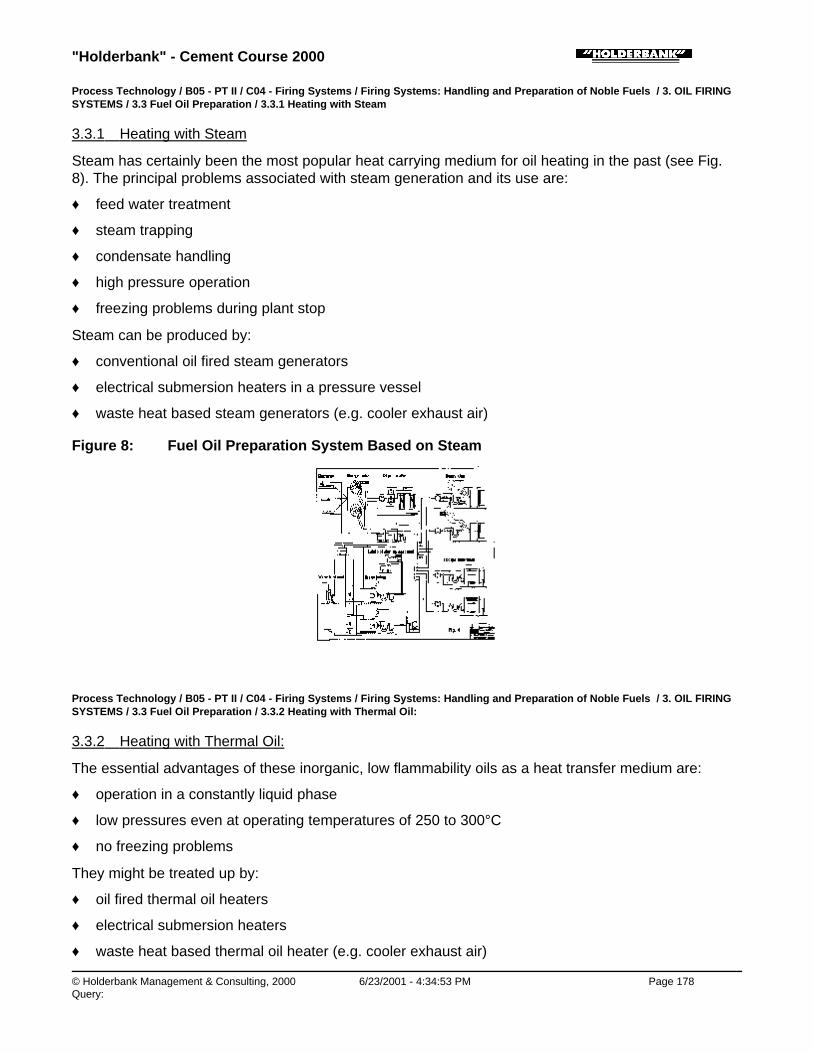
"Holderbank" - Cement Course 2000
© Holderbank Management & Consulting, 2000 6/23/2001 - 4:34:53 PM Page 178Query:
Process Technology / B05 - PT II / C04 - Firing Systems / Firing Systems: Handling and Preparation of Noble Fuels / 3. OIL FIRINGSYSTEMS / 3.3 Fuel Oil Preparation / 3.3.1 Heating with Steam
3.3.1 Heating with Steam
Steam has certainly been the most popular heat carrying medium for oil heating in the past (see Fig.8). The principal problems associated with steam generation and its use are:
♦ feed water treatment
♦ steam trapping
♦ condensate handling
♦ high pressure operation
♦ freezing problems during plant stop
Steam can be produced by:
♦ conventional oil fired steam generators
♦ electrical submersion heaters in a pressure vessel
♦ waste heat based steam generators (e.g. cooler exhaust air)
Figure 8: Fuel Oil Preparation System Based on Steam
Process Technology / B05 - PT II / C04 - Firing Systems / Firing Systems: Handling and Preparation of Noble Fuels / 3. OIL FIRINGSYSTEMS / 3.3 Fuel Oil Preparation / 3.3.2 Heating with Thermal Oil:
3.3.2 Heating with Thermal Oil:
The essential advantages of these inorganic, low flammability oils as a heat transfer medium are:
♦ operation in a constantly liquid phase
♦ low pressures even at operating temperatures of 250 to 300°C
♦ no freezing problems
They might be treated up by:
♦ oil fired thermal oil heaters
♦ electrical submersion heaters
♦ waste heat based thermal oil heater (e.g. cooler exhaust air)
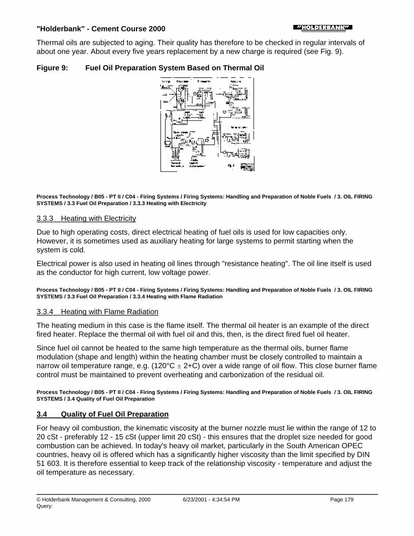
"Holderbank" - Cement Course 2000
© Holderbank Management & Consulting, 2000 6/23/2001 - 4:34:54 PM Page 179Query:
Thermal oils are subjected to aging. Their quality has therefore to be checked in regular intervals ofabout one year. About every five years replacement by a new charge is required (see Fig. 9).
Figure 9: Fuel Oil Preparation System Based on Thermal Oil
Process Technology / B05 - PT II / C04 - Firing Systems / Firing Systems: Handling and Preparation of Noble Fuels / 3. OIL FIRINGSYSTEMS / 3.3 Fuel Oil Preparation / 3.3.3 Heating with Electricity
3.3.3 Heating with Electricity
Due to high operating costs, direct electrical heating of fuel oils is used for low capacities only.However, it is sometimes used as auxiliary heating for large systems to permit starting when thesystem is cold.
Electrical power is also used in heating oil lines through "resistance heating". The oil line itself is usedas the conductor for high current, low voltage power.
Process Technology / B05 - PT II / C04 - Firing Systems / Firing Systems: Handling and Preparation of Noble Fuels / 3. OIL FIRINGSYSTEMS / 3.3 Fuel Oil Preparation / 3.3.4 Heating with Flame Radiation
3.3.4 Heating with Flame Radiation
The heating medium in this case is the flame itself. The thermal oil heater is an example of the directfired heater. Replace the thermal oil with fuel oil and this, then, is the direct fired fuel oil heater.
Since fuel oil cannot be heated to the same high temperature as the thermal oils, burner flamemodulation (shape and length) within the heating chamber must be closely controlled to maintain anarrow oil temperature range, e.g. (120°C ± 2+C) over a wide range of oil flow. This close burner flamecontrol must be maintained to prevent overheating and carbonization of the residual oil.
Process Technology / B05 - PT II / C04 - Firing Systems / Firing Systems: Handling and Preparation of Noble Fuels / 3. OIL FIRINGSYSTEMS / 3.4 Quality of Fuel Oil Preparation
3.4 Quality of Fuel Oil Preparation
For heavy oil combustion, the kinematic viscosity at the burner nozzle must lie within the range of 12 to20 cSt - preferably 12 - 15 cSt (upper limit 20 cSt) - this ensures that the droplet size needed for goodcombustion can be achieved. In today's heavy oil market, particularly in the South American OPECcountries, heavy oil is offered which has a significantly higher viscosity than the limit specified by DIN51 603. It is therefore essential to keep track of the relationship viscosity - temperature and adjust theoil temperature as necessary.

"Holderbank" - Cement Course 2000
© Holderbank Management & Consulting, 2000 6/23/2001 - 4:34:54 PM Page 180Query:
Fig. 10 shows the kinematic viscosity of different fuel oil types in function of temperature. The upperlimits for atomization and pumping are indicated.
Fig. 11 shows a conversion table for the different viscosity units.
Furthermore it is important to keep the oil temperature constant within a very narrow range to have astable flame.
Figure 10: Kinematic Viscosity of Current Fuel Oils
Figure 11: Conversion of Different Viscosity Scales
Process Technology / B05 - PT II / C04 - Firing Systems / Firing Systems: Handling and Preparation of Noble Fuels / 3. OIL FIRINGSYSTEMS / 3.5 Control Loops in the Fuel Oil Circuit
3.5 Control Loops in the Fuel Oil Circuit
Between storage tanks and fuel oil burners, there are generally four control loops installed, which haveto keep constant the following values:
1) Fuel oil temperature at the storage tank suction point.
2) Pressure in the oil circuit line between storage tanks and preparation station (Bypass of a part ofthe flow back to the storage tank; see Fig 7).
3) Temperature of the fuel oil to be atomized (Preparation Station).
4) Atomizing pressure: Accomplished by means of a bypass valve which leads part of the flow back tothe storage tank (see Fig. 7) or by means of variable speed high pressure pumps, which aredirectly controlled by the oil flow meter.
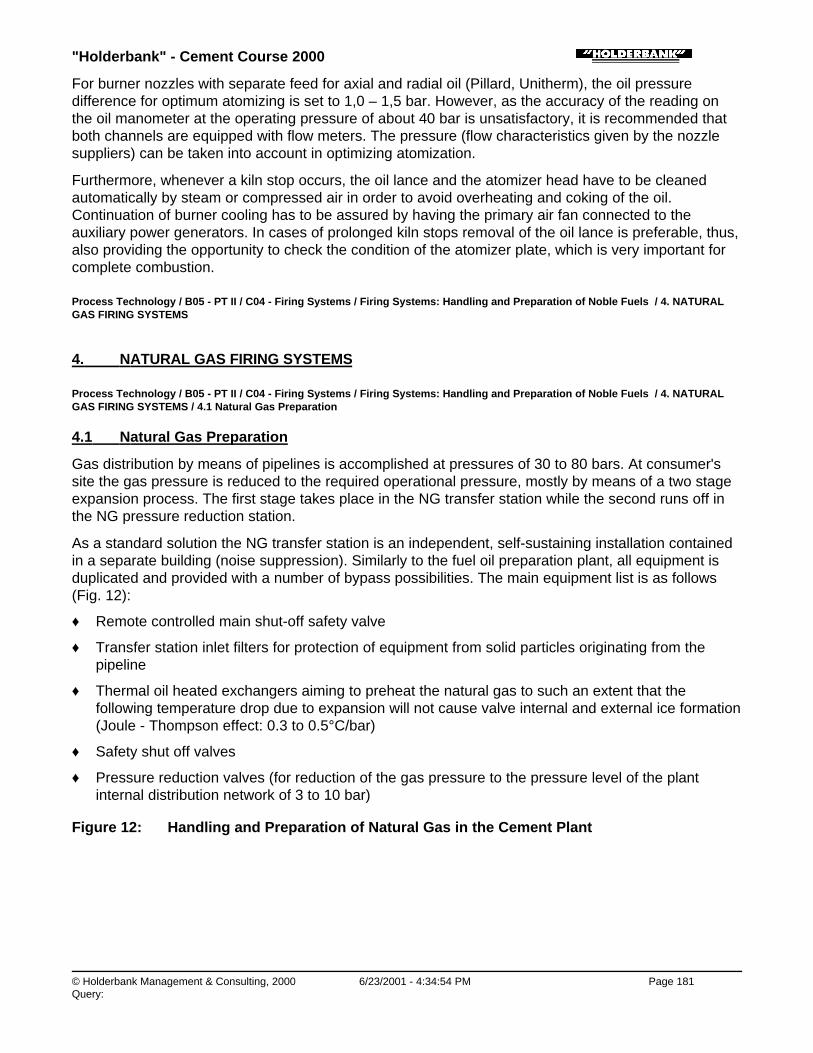
"Holderbank" - Cement Course 2000
© Holderbank Management & Consulting, 2000 6/23/2001 - 4:34:54 PM Page 181Query:
For burner nozzles with separate feed for axial and radial oil (Pillard, Unitherm), the oil pressuredifference for optimum atomizing is set to 1,0 – 1,5 bar. However, as the accuracy of the reading onthe oil manometer at the operating pressure of about 40 bar is unsatisfactory, it is recommended thatboth channels are equipped with flow meters. The pressure (flow characteristics given by the nozzlesuppliers) can be taken into account in optimizing atomization.
Furthermore, whenever a kiln stop occurs, the oil lance and the atomizer head have to be cleanedautomatically by steam or compressed air in order to avoid overheating and coking of the oil.Continuation of burner cooling has to be assured by having the primary air fan connected to theauxiliary power generators. In cases of prolonged kiln stops removal of the oil lance is preferable, thus,also providing the opportunity to check the condition of the atomizer plate, which is very important forcomplete combustion.
Process Technology / B05 - PT II / C04 - Firing Systems / Firing Systems: Handling and Preparation of Noble Fuels / 4. NATURALGAS FIRING SYSTEMS
4. NATURAL GAS FIRING SYSTEMS
Process Technology / B05 - PT II / C04 - Firing Systems / Firing Systems: Handling and Preparation of Noble Fuels / 4. NATURALGAS FIRING SYSTEMS / 4.1 Natural Gas Preparation
4.1 Natural Gas Preparation
Gas distribution by means of pipelines is accomplished at pressures of 30 to 80 bars. At consumer'ssite the gas pressure is reduced to the required operational pressure, mostly by means of a two stageexpansion process. The first stage takes place in the NG transfer station while the second runs off inthe NG pressure reduction station.
As a standard solution the NG transfer station is an independent, self-sustaining installation containedin a separate building (noise suppression). Similarly to the fuel oil preparation plant, all equipment isduplicated and provided with a number of bypass possibilities. The main equipment list is as follows(Fig. 12):
♦ Remote controlled main shut-off safety valve
♦ Transfer station inlet filters for protection of equipment from solid particles originating from thepipeline
♦ Thermal oil heated exchangers aiming to preheat the natural gas to such an extent that thefollowing temperature drop due to expansion will not cause valve internal and external ice formation(Joule - Thompson effect: 0.3 to 0.5°C/bar)
♦ Safety shut off valves
♦ Pressure reduction valves (for reduction of the gas pressure to the pressure level of the plantinternal distribution network of 3 to 10 bar)
Figure 12: Handling and Preparation of Natural Gas in the Cement Plant
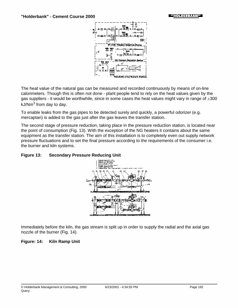
"Holderbank" - Cement Course 2000
© Holderbank Management & Consulting, 2000 6/23/2001 - 4:34:55 PM Page 182Query:
The heat value of the natural gas can be measured and recorded continuously by means of on-linecalorimeters. Though this is often not done - plant people tend to rely on the heat values given by thegas suppliers - it would be worthwhile, since in some cases the heat values might vary in range of ±300kJ/Nm3 from day to day.
To enable leaks from the gas pipes to be detected surely and quickly, a powerful odorizer (e.g.mercaptan) is added to the gas just after the gas leaves the transfer station.
The second stage of pressure reduction, taking place in the pressure reduction station, is located nearthe point of consumption (Fig. 13). With the exception of the NG heaters it contains about the sameequipment as the transfer station. The aim of this installation is to completely even out supply networkpressure fluctuations and to set the final pressure according to the requirements of the consumer i.e.the burner and kiln systems.
Figure 13: Secondary Pressure Reducing Unit
Immediately before the kiln, the gas stream is split up in order to supply the radial and the axial gasnozzle of the burner (Fig. 14).
Figure: 14: Kiln Ramp Unit

"Holderbank" - Cement Course 2000
© Holderbank Management & Consulting, 2000 6/23/2001 - 4:34:55 PM Page 183Query:
Process Technology / B05 - PT II / C04 - Firing Systems / Firing Systems: Handling and Preparation of Noble Fuels / 4. NATURALGAS FIRING SYSTEMS / 4.2 Safety Precautions
4.2 Safety Precautions
Process Technology / B05 - PT II / C04 - Firing Systems / Firing Systems: Handling and Preparation of Noble Fuels / 4. NATURALGAS FIRING SYSTEMS / 4.2 Safety Precautions / 4.2.1 Flexible Hoses Bursting
4.2.1 Flexible Hoses Bursting
Since there is some risk of the flexible gas hoses between kiln burner and gas supply line bursting or ofthe proceeding valves etc. failing, pressure monitors for the maximum and minimum pressure areinserted immediately before the hoses concerned. In the event of an emergency stop, a safety stopvalve, or two in series, are actuated to stop any further input of fuel at once.
Process Technology / B05 - PT II / C04 - Firing Systems / Firing Systems: Handling and Preparation of Noble Fuels / 4. NATURALGAS FIRING SYSTEMS / 4.2 Safety Precautions / 4.2.2 Leak Tests
4.2.2 Leak Tests
To check the gas pipes and fittings inside the plant for leaks the following methods are used:
♦ Normally leaks can be detected naturally as a result of adding odorizer.
♦ When machines are switched off, the hissing sound of the escaping gas is easily discernible.
♦ A somewhat riskier method is to run a naked flame along the gas pipe. This results in a flamingtorch being produced at the leak, which cannot be overlooked. There is no risk of this flame strikingback into the supply pipe (quenching distance, lack of oxygen), but escaped gas could cause anexplosion.
When constructing buildings which contain gas pipes, it is essential to allow for sufficient ventilation.This point does not usually give rise to any difficulty in cement works. But to be quite sure, certainitems of equipment can be fitted with guard flames from the start. Their task is to ignite any gas thatescapes before a large quantity of explosive mixture has a chance to collect.
A further possibility is to install gas detectors in critical places such as the gas preparation station orthe burner tunnel.
Process Technology / B05 - PT II / C04 - Firing Systems / Firing Systems: Handling and Preparation of Noble Fuels / 4. NATURALGAS FIRING SYSTEMS / 4.2 Safety Precautions / 4.2.3 Explosions in the Kiln
4.2.3 Explosions in the Kiln
"Holderbank" - Cement Course 2000
© Holderbank Management & Consulting, 2000 6/23/2001 - 4:34:55 PM Page 184Query:
The most important requirement is that the fuel should not be allowed to enter the kiln unintentionallyor at an uncontrolled rate, as this is essential to prevent explosions occurring in the kiln itself or in thesystems following it (e.g. preheater tower, EP).
This means that the fuel input has to be stopped immediately in the event of the flame going out. In thisrespect it must be said that extinction of the flame in a hot kiln has never been observed so far, evenduring material rushes.
Nevertheless during the start up of the cold kiln, lifting off and extinction of the flame can occur, forexample caused by partly blocked burneroutlets which lead to increased injection speed of the gas. Ifthe gas is injected with a too high speed, the flame can be blown out.
Therefore careful observation of the flame during the whole start up period is of utmost importance. Inthe case of the flame going out, fuel supply has to be cut off immediately to prevent explosions.
Excessive fuel input can also cause explosions because of CO accumulations. Therefore carefulmonitoring of CO concentrations is important.
Process Technology / B05 - PT II / C04 - Firing Systems / Firing Systems: Handling and Preparation of Noble Fuels / 5. LIST OFREFERENCES
5. LIST OF REFERENCES
1) "Firing Systems"VA 82/4898/E
2) "Flames and Burners"VA 93/4056/E
3) "State of Technology of Rotary Kiln Burners"F. Schneider, PT 96/14078/E
4) "Proportioning of Bulk Materials"F Bucher, PT 96/14071/E
5) "A Review of Coal Firing Systems and their Influence on Heat Consumption,Production and Kiln Operation"H. Meier, PT 96/14210/E

"Holderbank" - Cement Course 2000
© Holderbank Management & Consulting, 2000 6/23/2001 - 4:34:55 PM Page 185Query:
Process Technology / B05 - PT II / C04 - Firing Systems / Safe Handling of Coal and other Combustible dusts
Safe Handling of Coal and other Combustible dustsF. Schneider(Original title: Basic safety theory of solid fuel preparation)
1. INTRODUCTION
2. BASIC PRINCIPLES FOR HANDLING PULVERIZED FUELS
2.1 Development of Dust Explosions and Fires
2.2 Possible Protective Measures against Dust Explosions and Fires
3. APPLICATION OF PROTECTIVE MEASURES IN THE INDUSTRIAL ENVIRONMENT
3.1 Preventive Safety Measures
3.2 Explosion Protection Techniques
4. LITERATURE
4.1 Approximate Values for Explosion Limits and Ignition Temperatures
"Holderbank" - Cement Course 2000
© Holderbank Management & Consulting, 2000 6/23/2001 - 4:34:56 PM Page 186Query:
SUMMARY
Dust explosions can only occur when - besides certain marginal conditions - the following factorssimultaneously are present:
♦ Stirred-up, combustible dust
♦ Oxygen
♦ Source of ignition
A basic distinction is made between active explosion protection techniques (prevention of theoccurrence of explosions) and design related explosion protection (reduction of the effects ofexplosions).
In practice, the following measures are applied:
1) Preventive Measures:Their aim is:
∗ to exclude possible ignition sources within the installation∗ to prevent the building up of coal dust deposits, wherever possible∗ to detect the source of a fire as soon as possible∗ to extinguish the fire with a minimum of danger
2) Explosion Protection Measures:∗ Either active protective measures involving inert gas operation. This is the case when the
oxygen concentration within the pulverizing plant is kept below the critical limit - for solidfuels dust, as a rule, less than 12 to 14% - as long as combustible dust is present in thesystem.
∗ Or, alternatively, design related protective measures based on the use of explosion resistantconstruction in accordance with VDI Guidelines No. 3673.
Process Technology / B05 - PT II / C04 - Firing Systems / Safe Handling of Coal and other Combustible dusts / 1. INTRODUCTION
1. INTRODUCTION
The operational safety of solid fuel plants is an important decision factor when the choice of thepreparation system is being considered. For this reason, the three most important basic systems will bebriefly reviewed here, differentiated according to their different methods of handling gas and coal dust(Fig. 1).
Fig. 1 Firing Systems

"Holderbank" - Cement Course 2000
© Holderbank Management & Consulting, 2000 6/23/2001 - 4:34:56 PM Page 187Query:
a) Direct firingIn this system, the combustible dust is conveyed into the kiln together with the exhaust gasesresulting from the drying-cum-grinding operation. This arrangement represents the simplest designand is easily controllable from the safety point of view. However, there are also considerabledisadvantages involved with the use of this system in clinker manufacture with increasing ballastcontent of the fuel.
b) Semi-direct firingIn this system the combustible dust is separated in an intermediate silo, while the mill exhausts,possibly as recirculated air, are conveyed to the cement kiln as the primary air supply. This resultsin the technical disadvantages of direct firing being reduced to a certain extent - at the expense of asomewhat more complex installation - but all drying gases are still conveyed to the kiln.
c) Indirect firingThis solution is surely the best possible version when the operation of a rotary kiln is beingconsidered. The pulverized fuel can be conveyed to the firing system from the silo independentlyfrom the pulverizing plant operation. The firing system can be operated with a primary air ratiodesigned for optimal flame generation, as the mill exhaust gases are filtered. Against this we haveincreased risks with respect to safety due to the operation of the filters and silos and higher controltechnique requirements.
Further discussion of the decision criteria for the selection of an optimal preparation system is outsidethe scope of this lecture. However, it is certain that when factors such as
♦ the growing size of installation
♦ installations with several firing systems
♦ the use of fuels rich in ballast
♦ the use of fuels of widely differing quality characteristics
are considered, the decision will be influenced in favor of the indirect firing system which needs farmore advanced and sophisticated safety techniques than the simpler direct firing system does.
For this reason the damage prevention possibilities discussed below refer basically to the indirect firingsystem and must be adjusted accordingly if they are applied to other systems.
Process Technology / B05 - PT II / C04 - Firing Systems / Safe Handling of Coal and other Combustible dusts / 2. BASICPRINCIPLES FOR HANDLING PULVERIZED FUELS
2. BASIC PRINCIPLES FOR HANDLING PULVERIZED FUELS

"Holderbank" - Cement Course 2000
© Holderbank Management & Consulting, 2000 6/23/2001 - 4:34:56 PM Page 188Query:
Process Technology / B05 - PT II / C04 - Firing Systems / Safe Handling of Coal and other Combustible dusts / 2. BASICPRINCIPLES FOR HANDLING PULVERIZED FUELS / 2.1 Development of Dust Explosions and Fires
2.1 Development of Dust Explosions and Fires
In order to effectively ensure the safety of a solid fuel preparation plant, we must first be aware of thesequence of the possible fuel reactions.
Dust explosions can only occur if the following three conditions are simultaneously fulfilled (Fig. 2).
a) Stirred-up, combustible dust present in explosive concentration.
b) Air or oxygen above the critical concentration, for coal dust as a rule, above 14%, for lignite above12%.
c) An ignition source possessing energy above the minimal ignition energy (depending upon the typeof dust).
Fig. 2 Preliminary Conditions for an Explosion
After the ignition of an optimally explosive mixture in an enclosed space, the pressure increases moreor less rapidly until it reaches the maximal explosion pressure Pmax, and then decreases more or lessslowly to the original pressure, depending on the aerodynamic conditions (Fig. 3). While the maximumexplosion pressure is almost independent of the container’s form and size, and in case of coal andlignite dusts, amounts to approximately seven to nine times the initial pressure the maximum rate of
pressure rise max
dtdp
- which is a measure of the explosion violence - is dependent on the containervolume in accordance with the cubic law:
stKtconsVdtdp
tan31
max
=×
Kst is a material coefficient that depends on the type of dust, the degree of turbulence of the dust/airmixture at the moment of ignition, the grain size distribution, and the type of ignition source. Themethod for determining KSt is given in the VDI Guidelines No. 3673.
Fig. 3 Pressure Development of an Explosion Over Time
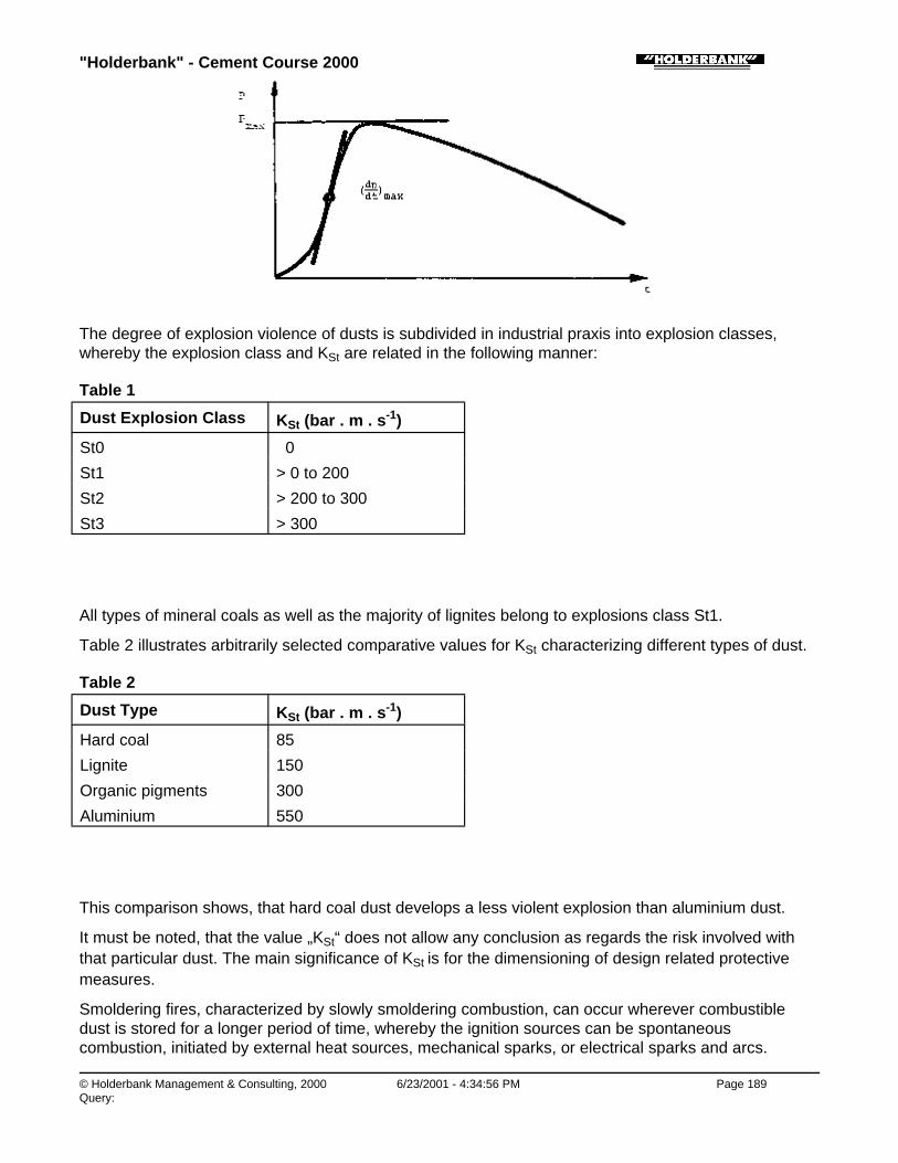
"Holderbank" - Cement Course 2000
© Holderbank Management & Consulting, 2000 6/23/2001 - 4:34:56 PM Page 189Query:
The degree of explosion violence of dusts is subdivided in industrial praxis into explosion classes,whereby the explosion class and KSt are related in the following manner:
Table 1
Dust Explosion Class KSt (bar . m . s-1)
St0 0
St1 > 0 to 200
St2 > 200 to 300
St3 > 300
All types of mineral coals as well as the majority of lignites belong to explosions class St1.
Table 2 illustrates arbitrarily selected comparative values for KSt characterizing different types of dust.
Table 2
Dust Type KSt (bar . m . s-1)
Hard coal 85
Lignite 150
Organic pigments 300
Aluminium 550
This comparison shows, that hard coal dust develops a less violent explosion than aluminium dust.
It must be noted, that the value „KSt“ does not allow any conclusion as regards the risk involved withthat particular dust. The main significance of KSt is for the dimensioning of design related protectivemeasures.
Smoldering fires, characterized by slowly smoldering combustion, can occur wherever combustibledust is stored for a longer period of time, whereby the ignition sources can be spontaneouscombustion, initiated by external heat sources, mechanical sparks, or electrical sparks and arcs.

"Holderbank" - Cement Course 2000
© Holderbank Management & Consulting, 2000 6/23/2001 - 4:34:57 PM Page 190Query:
Combustion propagation in smoldering fires is quite possible in very low oxygen concentrations.
Process Technology / B05 - PT II / C04 - Firing Systems / Safe Handling of Coal and other Combustible dusts / 2. BASICPRINCIPLES FOR HANDLING PULVERIZED FUELS / 2.2 Possible Protective Measures against Dust Explosions and Fires
2.2 Possible Protective Measures against Dust Explosions and Fires
In dust explosion protection techniques a distinction is made between active protective measures(prevention of the occurrence of explosions) and design related explosion protection (explosionresistant construction).
Process Technology / B05 - PT II / C04 - Firing Systems / Safe Handling of Coal and other Combustible dusts / 2. BASICPRINCIPLES FOR HANDLING PULVERIZED FUELS / 2.2 Possible Protective Measures against Dust Explosions and Fires / 2.2.1Active Explosion Protection
2.2.1 Active Explosion Protection
The active explosion protective techniques aim to exclude at least one of the three preliminaryconditions necessary for an explosion, i.e.:
♦ Stirring-up of combustible dust
♦ Oxygen content above the critical concentration of generally 12% for lignite or 14% for hard coal
♦ Ignition source
Process Technology / B05 - PT II / C04 - Firing Systems / Safe Handling of Coal and other Combustible dusts / 2. BASICPRINCIPLES FOR HANDLING PULVERIZED FUELS / 2.2 Possible Protective Measures against Dust Explosions and Fires / 2.2.1Active Explosion Protection / 2.2.1.1 Ignition Source
2.2.1.1 Ignition Source
In a pulverizing plant, ignition sources cannot be excluded with absolute certainty. It is always possiblethat mechanical sparks will be generated by the action of foreign bodies or by friction between movingmachine part or that the hot gas or coal feeding system will supply smoldering fuel particles.
Process Technology / B05 - PT II / C04 - Firing Systems / Safe Handling of Coal and other Combustible dusts / 2. BASICPRINCIPLES FOR HANDLING PULVERIZED FUELS / 2.2 Possible Protective Measures against Dust Explosions and Fires / 2.2.1Active Explosion Protection / 2.2.1.2 Combustible Dust
2.2.1.2 Combustible Dust
It is of course impossible to replace the combustible dust with a non-combustible material in thepreparation of fuel.
Thus, the only remaining possibility is the exclusion of air or oxygen respectively, or the reduction ofthe oxygen content in the fuel preparation plant.
Process Technology / B05 - PT II / C04 - Firing Systems / Safe Handling of Coal and other Combustible dusts / 2. BASICPRINCIPLES FOR HANDLING PULVERIZED FUELS / 2.2 Possible Protective Measures against Dust Explosions and Fires / 2.2.1Active Explosion Protection / 2.2.1.3 Air and Oxygen
2.2.1.3 Air and Oxygen
Dust explosions can be effectively prevented through inertization, i.e. the replacement of the oxygen inthe air by a non-combustible gas, particularly CO2 or N2, if it can be ensured that the inert gasatmosphere will be maintained as long as combustible dust is present in the system.
The maximal O2 concentration, below which no explosive propagation reactions of mineral coal dust
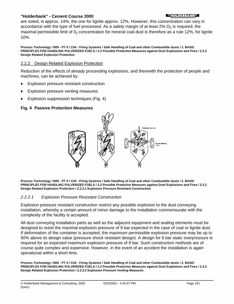
"Holderbank" - Cement Course 2000
© Holderbank Management & Consulting, 2000 6/23/2001 - 4:34:57 PM Page 191Query:
are noted, is approx. 14%, the one for lignite approx. 12%. However, this concentration can vary inaccordance with the type of fuel processed. As a safety margin of at least 2% O2 is required, themaximal permissible limit of 02 concentration for mineral coal dust is therefore as a rule 12%, for lignite10%.
Process Technology / B05 - PT II / C04 - Firing Systems / Safe Handling of Coal and other Combustible dusts / 2. BASICPRINCIPLES FOR HANDLING PULVERIZED FUELS / 2.2 Possible Protective Measures against Dust Explosions and Fires / 2.2.2Design Related Explosion Protection
2.2.2 Design Related Explosion Protection
Reduction of the effects of already proceeding explosions, and therewith the protection of people andmachines, can be achieved by:
♦ Explosion pressure resistant construction
♦ Explosion pressure venting measures
♦ Explosion suppression techniques (Fig. 4)
Fig. 4 Passive Protection Measures
Process Technology / B05 - PT II / C04 - Firing Systems / Safe Handling of Coal and other Combustible dusts / 2. BASICPRINCIPLES FOR HANDLING PULVERIZED FUELS / 2.2 Possible Protective Measures against Dust Explosions and Fires / 2.2.2Design Related Explosion Protection / 2.2.2.1 Explosion Pressure Resistant Construction
2.2.2.1 Explosion Pressure Resistant Construction
Explosion pressure resistant construction restrict any possible explosion to the dust conveyinginstallation, whereby a certain amount of minor damage to the installation commensurate with thecomplexity of the facility is accepted.
All dust conveying installation parts as well as the adjacent equipment and sealing elements must bedesigned to resist the maximal explosion pressure of 9 bar expected in the case of coal or lignite dust.If deformation of the container is accepted, the maximum permissible explosion pressure may be up to50% above its design value (pressure shock resistant design). A design for 6 bar static overpressure isrequired for an expected maximum explosion pressure of 9 bar. Such construction methods are ofcourse quite complex and expensive. However, in the event of an accident the installation is againoperational within a short time.
Process Technology / B05 - PT II / C04 - Firing Systems / Safe Handling of Coal and other Combustible dusts / 2. BASICPRINCIPLES FOR HANDLING PULVERIZED FUELS / 2.2 Possible Protective Measures against Dust Explosions and Fires / 2.2.2Design Related Explosion Protection / 2.2.2.2 Explosion Pressure Venting Measures

"Holderbank" - Cement Course 2000
© Holderbank Management & Consulting, 2000 6/23/2001 - 4:34:57 PM Page 192Query:
2.2.2.2 Explosion Pressure Venting Measures
In a broader sense explosion venting means all measures that serve to open temporarily orpermanently the previously closed installation in a safe direction, at the beginning or after a certainspreading of an explosion. The purpose of this is to prevent any overstressing of the mechanicalequipment beyond its pressure shock resistance. The strength of the equipment does not have to bedesigned for Pmax, but only for the reduced explosion pressure Pred (Fig. 5). A deformation of thecontainer may again be acceptable, but it must not burst.
Fig. 5 Pressure Response in Explosion-Pressure-Relief Techniques
The explosion pressure venting technique operates in the following manner: When the dynamicresponse pressure of the pressure venting installation is reached, predetermined breaking points, ripfoils or doors open to vent the shock wave outdoors, mainly by means of amply dimensioned dischargechannels. Immediately after the pressure venting system responds an increase in the temporal rate ofpressure rise can often be observed which is due to the higher turbulence caused during the venting ofthe shock wave. The pressure rise then quickly stops at Pred. Guidelines concerning the design layoutand dimensioning of the explosion pressure venting installations are contained in VDI Guidelines No.3673. If the method of explosion venting is applied not only the inserts of the containers such as filtercloths etc. must be considered but the expected recoil forces as well. With a pressure venting area of 1m2, a reduced explosion pressure of 2 bar, and under the assumption that the shock wave escapeswith the velocity of sound, a thrust of approx. 15 t acts upon the housing to be protected. This must beproperly supported or else the container may be torn from its foundations.
Process Technology / B05 - PT II / C04 - Firing Systems / Safe Handling of Coal and other Combustible dusts / 2. BASICPRINCIPLES FOR HANDLING PULVERIZED FUELS / 2.2 Possible Protective Measures against Dust Explosions and Fires / 2.2.2Design Related Explosion Protection / 2.2.2.3 Explosion Suppression
2.2.2.3 Explosion Suppression
In the explosion suppression techniques, the shock wave preceding the combustion front or theinfrared radiation of the combustion area is detected by a device which quickly distributes extinguishingagents under a propellant pressure of 60 to 120 bar by means of detonator-operated valves. With aprogrammed dynamic response pressure threshold (Pdyn) of the detectors, the maximal explosionpressure is again lowered to a reduced level (Pred).
Process Technology / B05 - PT II / C04 - Firing Systems / Safe Handling of Coal and other Combustible dusts / 2. BASICPRINCIPLES FOR HANDLING PULVERIZED FUELS / 2.2 Possible Protective Measures against Dust Explosions and Fires / 2.2.2Design Related Explosion Protection / 2.2.2.4 Limitation: Explosions from Ducts into Containers

"Holderbank" - Cement Course 2000
© Holderbank Management & Consulting, 2000 6/23/2001 - 4:34:58 PM Page 193Query:
2.2.2.4 Limitation: Explosions from Ducts into Containers
The described constructive protection techniques are effective under the condition that the reactiontakes place as described in the paragraph 2.1. The description is applicable to most explosions thatoccur in pulverizing plants. However, if an explosion strikes from a duct into a container, and in doingso the residual dust deposited there is stirred up with great turbulence and ignited, the reaction withinthe duct and the adjacent container can develop into a detonation of such dimensions that the resultingpressures can amount to 50 times the original pressure, accompanied by a combustion front travelingat supersonic speed, so that any relief or suppression installation is too sluggish in action. However,such events are, fortunately, relatively rare in coal operations. As a limit for a spontaneous explosionpropagation, an explosion characteristic of 100 bar.m.s-1 was observed under particular conditions in a200 m long pipeline of 1800 mm diameter located at the experimental mining research station inDortmund, while the usual values for coal are generally lower (approx. 85 bar.m.s-1).
However, if the principles of design related explosion protection are to be consequently pursued, everyduct conveying combustible dust in an explosive concentration and whose length exceeds five times itsdiameter must be safeguarded by an explosion vent placed ahead of its inlet into a container (such asa filter) (Fig. 6). Through this any explosion originating in the pipeline will be vented so that theprotective measures taken with respect to the adjacent container can be designed in accordance withthe criteria of an explosion starting in the container itself.
Fig. 6 Venting of a Duct in Front of a Precipitator
Process Technology / B05 - PT II / C04 - Firing Systems / Safe Handling of Coal and other Combustible dusts / 2. BASICPRINCIPLES FOR HANDLING PULVERIZED FUELS / 2.2 Possible Protective Measures against Dust Explosions and Fires / 2.2.3Prevention of Smoldering Fires
2.2.3 Prevention of Smoldering Fires
Smoldering fires in dust deposits are best prevented by preventing the possibility of greater quantitiesof dust accumulating. This is achieved through the appropriate design and slope of surfaces, pipelinesand supports, as well as sufficiently high gas speeds within the conveyor systems.
In silos where great quantities of combustible dust are stored for the plant’s own specific purposes, anycombustion that may occur must be detected as early as possible by carefully monitoring of the dusttemperature and the CO content of the silo atmosphere so that proper countermeasures can be taken.
Process Technology / B05 - PT II / C04 - Firing Systems / Safe Handling of Coal and other Combustible dusts / 3. APPLICATION OFPROTECTIVE MEASURES IN THE INDUSTRIAL ENVIRONMENT

"Holderbank" - Cement Course 2000
© Holderbank Management & Consulting, 2000 6/23/2001 - 4:34:58 PM Page 194Query:
3. APPLICATION OF PROTECTIVE MEASURES IN THE INDUSTRIAL ENVIRONMENT
The fire and explosion protection measures described above result for practical applications on the onehand in a network of preventive safety measures that significantly reduce the risk of an accident in theoperation of combustible dust installation, and on the other hand in actual explosion protectiontechniques that can prevent explosions, or at least shall hold the explosions within acceptable limits.
Process Technology / B05 - PT II / C04 - Firing Systems / Safe Handling of Coal and other Combustible dusts / 3. APPLICATION OFPROTECTIVE MEASURES IN THE INDUSTRIAL ENVIRONMENT / 3.1 Preventive Safety Measures
3.1 Preventive Safety Measures
The primary aim of preventive safety measures is to exclude possible ignition sources as causes ofconflagration or explosion if at all possible. In addition, they are also intended to prevent secondarydamage caused by the expulsion or stirring up of vast quantities of dust and their subsequent ignition.
These essentially preventive safety measures can be listed as follows:
♦ Temperature measurement of
• mill exhausts
• stored dust, preferably in silo entry and exit
♦ CO analysis of
• the silo atmosphere in silos
• mill exhaust after the filter
♦ Prevention of local overheating caused by friction in conveyor belt systems, high speeds of screwconveyors, bucket elevators, rotary valves, and bearing, and/or the detection of increasingtemperatures by measuring techniques. Relative velocities of moving parts < 1 m/s are consideredsafe, > 10 m/s are considered as potential ignition sources.
♦ Spark separators in air heaters
♦ Metal separator prior to the mill
♦ Prevention of electrostatic discharges by conductive connections and grounding of all installationparts
♦ Prevention of arcing in electrofilters by appropriate voltage control measures
♦ Prevention of dust accumulation possibilities:
• All surfaces to have a slope of at least 70° to the horizontal plane, especially in filter or silocones
• Regular disposal of dust deposits
• Gas speeds in conduits of more than 22 m/s
♦ Protection of the stored dust from the effects of external heat, for instance by spraying the siloexternally with cooling water
♦ Provision of inert gas supplies (e.g. CO2) for inertization of the silos in the case of smoldering fires
♦ Cleanliness of operating rooms
• Effective removal of the dust generated by means of proper dedusting installations
• Safe elimination of dust deposits by means of suitable auxiliary material

"Holderbank" - Cement Course 2000
© Holderbank Management & Consulting, 2000 6/23/2001 - 4:34:58 PM Page 195Query:
From the point of view of safety a solid fuel pulverizing plant must be operated as continuously aspossible, as critical situations often arise when the plant is not in operation. This fact must beconsidered when the capacity of the installation is being decided upon.
Process Technology / B05 - PT II / C04 - Firing Systems / Safe Handling of Coal and other Combustible dusts / 3. APPLICATION OFPROTECTIVE MEASURES IN THE INDUSTRIAL ENVIRONMENT / 3.2 Explosion Protection Techniques
3.2 Explosion Protection Techniques
Process Technology / B05 - PT II / C04 - Firing Systems / Safe Handling of Coal and other Combustible dusts / 3. APPLICATION OFPROTECTIVE MEASURES IN THE INDUSTRIAL ENVIRONMENT / 3.2 Explosion Protection Techniques / 3.2.1 Inert Gas Operation
3.2.1 Inert Gas Operation
As described under 2.2.1, active explosion protection in solid fuel pulverizing is practically limited toinert gas operation, i.e. operation with a maximum of 10 to 12% oxygen in the pulverizing plant,depending on type of fuel, as ignition sources and the stirring-up of dust can never be excluded withabsolute certainty.
Active explosion protection can be applied if hot inert gases such as the kiln exhaust from cement kilnsor hot gases from a combustion chamber, combined with a corresponding design for the mill’srecirculation gas are available. In the last case the dew point problem becomes significant, thereforethis solution is rarely applicable for very moist fuels, or special measures will have to be taken fordrying of the circulation gases.
If the inert gas atmosphere can be maintained with absolute certainty through appropriate design andinterlocking of the installation for as long as combustible dust is present in the system, design relatedprotection measures become in principle redundant. In those cases where these conditions cannot beguaranteed, for example, because hot gases with higher oxygen content are being used such asclinker cooler exhausts, or because of dew point problems, design related explosion protectiontechniques must be rigorously applied.
Process Technology / B05 - PT II / C04 - Firing Systems / Safe Handling of Coal and other Combustible dusts / 3. APPLICATION OFPROTECTIVE MEASURES IN THE INDUSTRIAL ENVIRONMENT / 3.2 Explosion Protection Techniques / 3.2.2 Explosion PressureResistant Construction
3.2.2 Explosion Pressure Resistant Construction
Explosion pressure resistant construction, i.e. the dimensioning of the installation section to resistmaximal explosion pressure, are mainly applicable where pressure venting methods cannot be used atall or only with difficulty, for geometrical reasons.
This is mostly the case in mills, and definitely in all conduit pipe systems where the length of thesystem exceeds five times the tube diameter. As a rule such components are designed to withstand astatic overpressure of 10 bar.
Process Technology / B05 - PT II / C04 - Firing Systems / Safe Handling of Coal and other Combustible dusts / 3. APPLICATION OFPROTECTIVE MEASURES IN THE INDUSTRIAL ENVIRONMENT / 3.2 Explosion Protection Techniques / 3.2.3 Explosion PressureVenting Measures
3.2.3 Explosion Pressure Venting Measures
All combustible dust conveying components that are not in themselves designed to be explosionpressure resistant, such as cyclone, filters, pulverized fuel silos, etc. are to be provided with properlydimensioned devices for explosion pressure venting. Thereby containers and all interconnectedaggregates such as bin vent filters, etc. must be dimensioned in pressure shock resistant design to

"Holderbank" - Cement Course 2000
© Holderbank Management & Consulting, 2000 6/23/2001 - 4:34:58 PM Page 196Query:
withstand the reduced explosion pressure.
Explosion venting openings within a particular building must be connected to properly dimensionedexhaust channels leading into the open. In order to prevent an explosion originating in the millspreading into the filter via the conduit pipe, the conduit pipe must be equipped with an explosion ventin front of its connection to the filter. This measure is not required for pneumatic conveying systems asin this design the dust concentration is normally above the explosion limit. In addition, the minimalignition energy is significantly higher under the operating conditions of pneumatic conveying than it is inthe case of stirring-up combustible dust in containers.
The area containing the vent opening for explosion pressure venting must not be accessible to anyonewhen the installation in operation.
VDI Guidelines No. 3673 can serve as a basis for the design of such an explosion pressure ventingsystem. Naturally, the system must be inspected regularly.
Process Technology / B05 - PT II / C04 - Firing Systems / Safe Handling of Coal and other Combustible dusts / 3. APPLICATION OFPROTECTIVE MEASURES IN THE INDUSTRIAL ENVIRONMENT / 3.2 Explosion Protection Techniques / 3.2.3 Explosion PressureVenting Measures / 3.2.3.1 Underpressure Protection
3.2.3.1 Underpressure Protection
After venting an explosion in very large enclosures such as pulverized fuel silos through explosion flapsconsiderable underpressure can develop inside the silo due to dynamic effects and due to coolingdown of the hot gases remaining in the silo after the explosion. Typical examples for the size ofunderpressure valves are given in Table 3. Guidelines for the individual design of underpressure valvescan be taken from the relevant literature (10).
Table 3
Volume m3 100 1000
Diameter m 3.4 .5
Cylindrical length m 9.5 22.0
Plate thickness mm 6 8
Max. negative pressure mbar 100 25
Required aspiration area m2 0.1 1.0
Process Technology / B05 - PT II / C04 - Firing Systems / Safe Handling of Coal and other Combustible dusts / 3. APPLICATION OFPROTECTIVE MEASURES IN THE INDUSTRIAL ENVIRONMENT / 3.2 Explosion Protection Techniques / 3.2.4 Explosion Suppression
3.2.4 Explosion Suppression
Techniques of explosion suppression can basically replace all the previously mentioned methods.However, in practical experience it has been seen that in pulverizing plants, the costs involved in theconsequent application of explosion suppression techniques are significantly higher than they are forexplosion pressure venting techniques and explosion pressure resistant construction methods, bothwith respect to procurement and maintenance of the sensitive equipment.
Thus applicability of explosion suppression may be primarily limited to existing, insufficiently protectedpulverizing plants whose retrofitting in accordance with alternative protection techniques would beentirely uneconomical.

"Holderbank" - Cement Course 2000
© Holderbank Management & Consulting, 2000 6/23/2001 - 4:34:59 PM Page 197Query:
Process Technology / B05 - PT II / C04 - Firing Systems / Safe Handling of Coal and other Combustible dusts / 3. APPLICATION OFPROTECTIVE MEASURES IN THE INDUSTRIAL ENVIRONMENT / 3.2 Explosion Protection Techniques / 3.2.5 Fire ExtinguishingMeasures
3.2.5 Fire Extinguishing Measures
If an accumulation of considerable quantities of combustible dust can be prevented inside the actualpulverizing plant (except in pulverized fuel silos), any fires that may arise following an explosion will notbe able to grow to any significant size. The installation of a fire extinguishing system can neverthelessstill be recommended for cloth filters and electofilters.
In the case of smoldering fires in pulverized fuel silos, all further fuel supply must be stoppedimmediately. Following this, the silo exit must be made airtight and the silo atmosphere flooded withCO2. Sufficient time must now pass until the temperature conditions have normalized. Anunderpressure valve is required in order to avoid collapsing of the silo due to the vacuum producedduring cooling down. The above procedures can take several days, depending on the size of thesmolder location. An alternative technique is to deliver the fuel as quickly as possible to the burnersystem via the dosing and conveyor systems. Of course this method is possible only when the dosingand conveying systems are heat-resistant, dustproof and explosion resistant. In addition, under nocircumstances is glowing fuel to be returned to the silo, as for instance via overflow feeders.
Fig. 7 shows the practical preventive safety measures for pulverized fuel silos. In Fig. 8 the applicationof design related protective measures for solid fuel preparation is illustrated.
Fig. 7 Preventive and Safety Measures for Coal Dust Silos
Fig. 8 Example to Show the Application of Design Related Explosion Protection

"Holderbank" - Cement Course 2000
© Holderbank Management & Consulting, 2000 6/23/2001 - 4:34:59 PM Page 198Query:
Process Technology / B05 - PT II / C04 - Firing Systems / Safe Handling of Coal and other Combustible dusts / 4. LITERATURE
4. LITERATURE
1) VDI Guidelines 2263Verhütung von Staubbränden und Staubexplosionen
2) VDI Guidelines 3673Druckentlastung von Staubexplosionen
3) VDI Report No. 304Sichere Handhabung brennbarer Stäube
4) Arbeitskreis der chemischen Industrie, October 1, 1973Sicherheitsmassnahmen gegen Staubbrände und StaubexplosionenPublished by BASF, Bayer, Ciba-Geigy and Farbwerke Hoechst
5) Dr. W. BartknechtExplosions, Course Prevention ProtectionSpringer Verlag, Berlin, Heidelberg, New York, 1981
6) K.N. PalmerDust Explosions and FiresLondon, Chapman and Hall, 1973
7) H. WibbelhoffDer Umgang mit Kohlenstaub in der ZementindustrieSteine und Erden 2/1978
8) F. SchneiderKohlenaufbereitung und Kohlenfeuerung für ZementdrehöfenZement, Kalk, Gips, No. 7/1976
9) E.W. Scholl, D. Reeh, W. Wiemann, M. Faber, G. Kühnen, H. Beck, N. GlienkeBrenn- und Explosionskenngrössen von StäubenSTF-Report No. 2 - 79 (as well as BVS-Report) ** see paragraph 4.1
10) W. Wiemann, R. Bauer, F. MöllerUnterdruck-Sicherung von Silos nach Staubexplosionen bei Anwendung von ExplosionsklappenVDI Report No. 701, 1988, Volume II
Process Technology / B05 - PT II / C04 - Firing Systems / Safe Handling of Coal and other Combustible dusts / 4. LITERATURE / 4.1Approximate Values for Explosion Limits and Ignition Temperatures
4.1 Approximate Values for Explosion Limits and Ignition Temperatures
The numerical values of the following data are depending on the test procedure applied and can varywithin certain limits according to the origin and geological age of the coals. The following values referto the Literature (9).
♦ Explosion Limits
1) Dust concentration:∗ lower explosion limits 40 to 130 g/m3∗ upper explosion limits 2000 to 6000 g/m3
2) Oxygen concentration:

"Holderbank" - Cement Course 2000
© Holderbank Management & Consulting, 2000 6/23/2001 - 4:34:59 PM Page 199Query:
∗ hard coal 14%∗ lignite 12%
3) Concentration of non-combustible parts (ash):∗ hard coal (-medium volatile bituminous) 65%
♦ Ignition Temperature
Cloud °C Layer °C
Lignite 380 to 450 225 to 300
Hard coal 590 to 710 245 to 380
Petrol coke 690 280
"Holderbank" - Cement Course 2000
© Holderbank Management & Consulting, 2000 6/23/2001 - 4:34:59 PM Page 200Query:
Process Technology / B05 - PT II / C05 - Burners and Flames
C05 - Burners and Flames
"Holderbank" - Cement Course 2000
© Holderbank Management & Consulting, 2000 6/23/2001 - 4:35:00 PM Page 201Query:
Process Technology / B05 - PT II / C05 - Burners and Flames / Burners and Flames
Burners and FlamesD. PaulingPT 98/14354/E
1. Terminology
2. Burners
2.1 Mono Channel - / Straight Burners
2.1.1 Burner Design
2.1.2 Burner Characterization
2.2 Multi Channel Burners
2.2.1 Burner Types
2.2.2 Burner Design Recommendations
2.3 Fuel Oil Atomizers
2.3.1 Mechanical Atomizers with Fixed Orifice and Variable Pressure
2.3.2 Mechanical Atomizers with Variable Orifice and Constant Pressure
2.3.3 Nozzles with Assisted Atomization through Steam or Compressed Air
2.4 Natural Gas Burners
3. flames
3.1 Prerequisites for the Ideal Flame
3.2 Flame Characteristics of the Different Burner Systems
3.2.1 Single Channel Burner
3.2.2 Multi Channel Burner
3.3 Factors Influencing the Flame
3.3.1 Primary Air Momentum
3.3.2 Position of the Burner in the Kiln
3.3.3 Alignment of the Burner in the Kiln
3.3.4 Secondary Air Temperature
3.3.5 Excess Air
3.3.6 Interaction Flame - Material Bed
3.3.7 Burner Dimensions
3.3.8 Pulverized Coal Characteristics
3.3.9 Fuel Oil Flame Adjustments
3.3.10 Natural Gas Flame Adjustments
"Holderbank" - Cement Course 2000
© Holderbank Management & Consulting, 2000 6/23/2001 - 4:35:00 PM Page 202Query:
3.3.11 Combined Firing of Different Fuels
3.3.12 Oxygen Enrichment
3.4 Combustion Indicators
3.4.1 Clinker Quality
3.4.2 Sintering Zone Temperature
3.4.3 Coating Formation
3.4.4 Exhaust Gas Analysis
3.4.5 Kiln Inlet Temperature
3.4.6 Volatilization of Circulating Elements
3.5 NOx Formation
3.6 Flame Adjustment Procedure
4. secondary firing / precalciner
5. list of references
6. ANNEX
6.1 Formulas and Definitions for the Calculation of Burner Momentum and Swirl Number
Introduction
The function of the burner is to introduce the fuel into the burning zone.
The propagation of the combustion process depends on how fast the combustible comes into contactwith oxygen. It is therefore the essential function of the burner to regulate this mixing processadequately in order to achieve a correct flame shape.
This process must take place in such a fashion that the heat is released at exactly the right placewithout producing any damaging effects and without producing excessive pollutant elements such asNOx, SOx and CO. Consequently, any optimization of the burning process must start with the correctadjustment of the flame.
This paper describes how the flame can be adjusted, what burner types are available and under whatconditions they work best.
Process Technology / B05 - PT II / C05 - Burners and Flames / Burners and Flames / 1. TERMINOLOGY
1. TERMINOLOGY
• Primary air + secondary air + false air = combustion air
• Stoichiometric combustion air + excess air = combustion air

"Holderbank" - Cement Course 2000
© Holderbank Management & Consulting, 2000 6/23/2001 - 4:35:00 PM Page 203Query:
Figure 1: Terminology of Combustion Air
Process Technology / B05 - PT II / C05 - Burners and Flames / Burners and Flames / 2. BURNERS
2. BURNERS
Process Technology / B05 - PT II / C05 - Burners and Flames / Burners and Flames / 2. BURNERS / 2.1 Mono Channel - / StraightBurners
2.1 Mono Channel - / Straight Burners
Process Technology / B05 - PT II / C05 - Burners and Flames / Burners and Flames / 2. BURNERS / 2.1 Mono Channel - / StraightBurners / 2.1.1 Burner Design
2.1.1 Burner Design
The mono channel burner is the most simple burner design. With this burner type, coal dust and all theprimary air is injected together through a single tube. Usually this type is used for long kilns, equippedwith direct firing.
Mono channel / straight burners can also be used for fuel oil firing or for a combination of coal and oilfiring (additional channel for the oil nozzle in the center).
Conical burner tips can be used to increase the injection velocity (Fig. 2).
Figure 2: Straight Burner
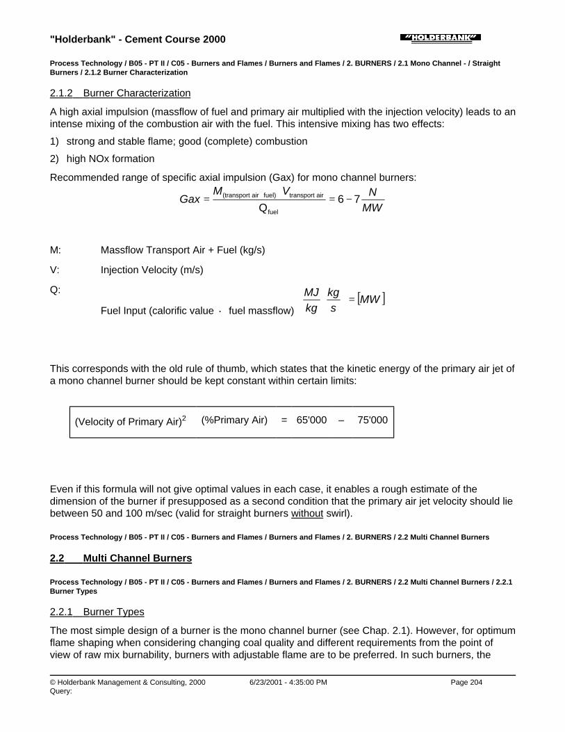
"Holderbank" - Cement Course 2000
© Holderbank Management & Consulting, 2000 6/23/2001 - 4:35:00 PM Page 204Query:
Process Technology / B05 - PT II / C05 - Burners and Flames / Burners and Flames / 2. BURNERS / 2.1 Mono Channel - / StraightBurners / 2.1.2 Burner Characterization
2.1.2 Burner Characterization
A high axial impulsion (massflow of fuel and primary air multiplied with the injection velocity) leads to anintense mixing of the combustion air with the fuel. This intensive mixing has two effects:
1) strong and stable flame; good (complete) combustion
2) high NOx formation
Recommended range of specific axial impulsion (Gax) for mono channel burners:
MWNVM
Gax 76Qfuel
air transportfuel)air (transport −=⋅
= +
M: Massflow Transport Air + Fuel (kg/s)
V: Injection Velocity (m/s)
Q:
Fuel Input (calorific value · fuel massflow) [ ]MW
skg
kgMJ
=
⋅
This corresponds with the old rule of thumb, which states that the kinetic energy of the primary air jet ofa mono channel burner should be kept constant within certain limits:
(Velocity of Primary Air)2 (%Primary Air) = 65'000 – 75'000
Even if this formula will not give optimal values in each case, it enables a rough estimate of thedimension of the burner if presupposed as a second condition that the primary air jet velocity should liebetween 50 and 100 m/sec (valid for straight burners without swirl).
Process Technology / B05 - PT II / C05 - Burners and Flames / Burners and Flames / 2. BURNERS / 2.2 Multi Channel Burners
2.2 Multi Channel Burners
Process Technology / B05 - PT II / C05 - Burners and Flames / Burners and Flames / 2. BURNERS / 2.2 Multi Channel Burners / 2.2.1Burner Types
2.2.1 Burner Types
The most simple design of a burner is the mono channel burner (see Chap. 2.1). However, for optimumflame shaping when considering changing coal quality and different requirements from the point ofview of raw mix burnability, burners with adjustable flame are to be preferred. In such burners, the
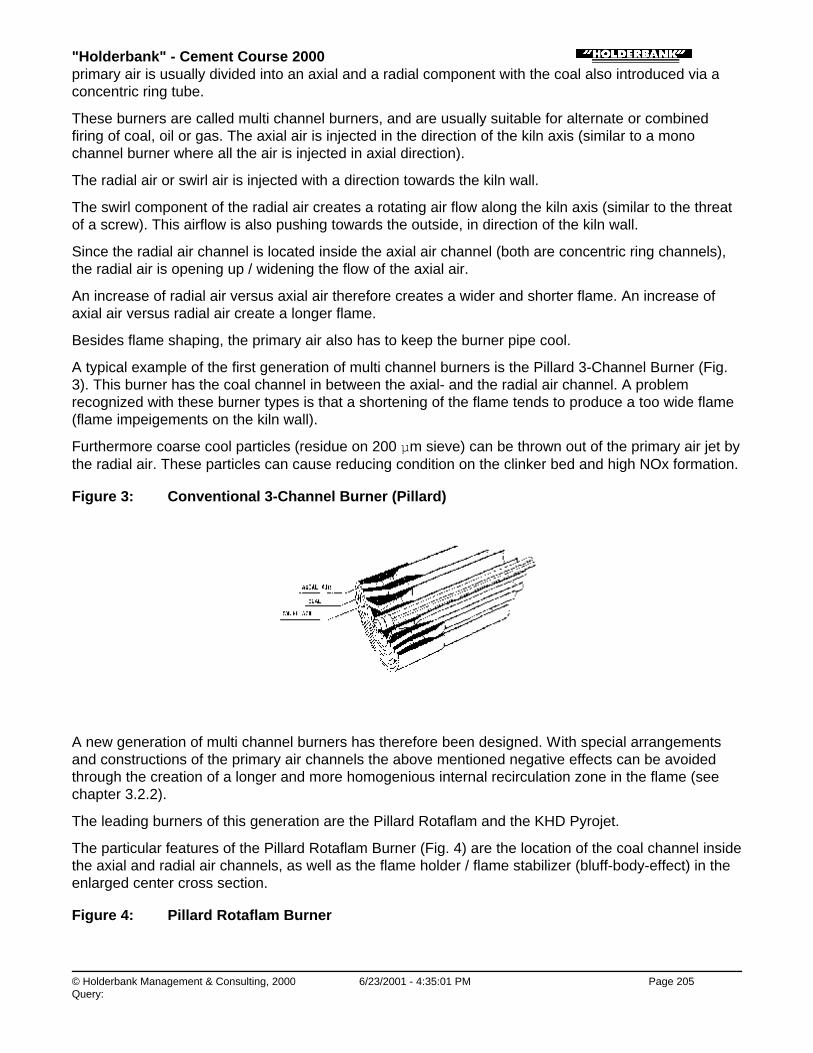
"Holderbank" - Cement Course 2000
© Holderbank Management & Consulting, 2000 6/23/2001 - 4:35:01 PM Page 205Query:
primary air is usually divided into an axial and a radial component with the coal also introduced via aconcentric ring tube.
These burners are called multi channel burners, and are usually suitable for alternate or combinedfiring of coal, oil or gas. The axial air is injected in the direction of the kiln axis (similar to a monochannel burner where all the air is injected in axial direction).
The radial air or swirl air is injected with a direction towards the kiln wall.
The swirl component of the radial air creates a rotating air flow along the kiln axis (similar to the threatof a screw). This airflow is also pushing towards the outside, in direction of the kiln wall.
Since the radial air channel is located inside the axial air channel (both are concentric ring channels),the radial air is opening up / widening the flow of the axial air.
An increase of radial air versus axial air therefore creates a wider and shorter flame. An increase ofaxial air versus radial air create a longer flame.
Besides flame shaping, the primary air also has to keep the burner pipe cool.
A typical example of the first generation of multi channel burners is the Pillard 3-Channel Burner (Fig.3). This burner has the coal channel in between the axial- and the radial air channel. A problemrecognized with these burner types is that a shortening of the flame tends to produce a too wide flame(flame impeigements on the kiln wall).
Furthermore coarse cool particles (residue on 200 µm sieve) can be thrown out of the primary air jet bythe radial air. These particles can cause reducing condition on the clinker bed and high NOx formation.
Figure 3: Conventional 3-Channel Burner (Pillard)
A new generation of multi channel burners has therefore been designed. With special arrangementsand constructions of the primary air channels the above mentioned negative effects can be avoidedthrough the creation of a longer and more homogenious internal recirculation zone in the flame (seechapter 3.2.2).
The leading burners of this generation are the Pillard Rotaflam and the KHD Pyrojet.
The particular features of the Pillard Rotaflam Burner (Fig. 4) are the location of the coal channel insidethe axial and radial air channels, as well as the flame holder / flame stabilizer (bluff-body-effect) in theenlarged center cross section.
Figure 4: Pillard Rotaflam Burner
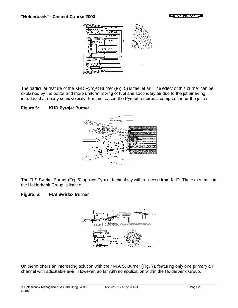
"Holderbank" - Cement Course 2000
© Holderbank Management & Consulting, 2000 6/23/2001 - 4:35:01 PM Page 206Query:
The particular feature of the KHD Pyrojet Burner (Fig. 5) is the jet air. The effect of this burner can beexplained by the better and more uniform mixing of fuel and secondary air due to the jet air beingintroduced at nearly sonic velocity. For this reason the Pyrojet requires a compressor for the jet air.
Figure 5: KHD Pyrojet Burner
The FLS Swirlax Burner (Fig. 6) applies Pyrojet technology with a license from KHD. The experience inthe Holderbank Group is limited.
Figure. 6: FLS Swirlax Burner
Unitherm offers an interesting solution with their M.A.S. Burner (Fig. 7), featuring only one primary airchannel with adjustable swirl. However, so far with no application within the Holderbank Group.

"Holderbank" - Cement Course 2000
© Holderbank Management & Consulting, 2000 6/23/2001 - 4:35:02 PM Page 207Query:
Figure 7: Unitherm M.A.S. Burner
Process Technology / B05 - PT II / C05 - Burners and Flames / Burners and Flames / 2. BURNERS / 2.2 Multi Channel Burners / 2.2.2Burner Design Recommendations
2.2.2 Burner Design Recommendations
(Calculation of Gax and Sb : see Annex)
• Specific Axial Impulsion: Gax = 3 - 7
low volatile coal (10% volatiles): Gax = 7
high volatile coal (35% volatiles): Gax = 3
The axial impulsion affects the overall entrainment into the flame. In general a higher axialimpulsion results in enhanced mixing and higher NOx emission levels.
• Swirl Number: Normal Range: Sb = 0.1 - 0.25
Maximum Range: Sb = 0.4
In general higher tangential momentum (expressed through the swirl number) results in a more rapidheat release in the near burner zone and higher NOx emission levels.
♦ Primary Air Ratio: 10 - 12%
♦ Experience with these new generation (low primary air) burners has shown, that primary air ratiosof 6 - 8% are on the technical limit below which it is no longer possible to guarantee stablecombustion conditions.
♦ With primary air ratios of 6 - 8%, any disturbance of the burning process tends to shift combustionto the back kiln zone, producing high kiln inlet temperatures and poor clinker quality(underburning). Therefore in designing the primary air content for modern burners, a minimum of

"Holderbank" - Cement Course 2000
© Holderbank Management & Consulting, 2000 6/23/2001 - 4:35:02 PM Page 208Query:
10% is recommended (including transport air in coal fired systems).
♦ Seen from a heat saving point of view the primary air ratio should be as low as possible in order torecuperate as much hot secondary air as possible. On the other hand, the kinetic energy of the fuelair mixture must be sufficiently high to provide a good mixture with the secondary air to ensurerapid burning.
♦
♦ Axial air velocity (injection): 100 - 190 m/s (Pyrojet: 300 m/s)
♦ Radial air velocity (injection): 100 - 190 m/s
♦ Pressure of radial and axial air: 150 - 200 mbar (Pyrojet axial air: 0.5 - 1 bar)
♦ Transport air coal (injection): 20 - 30 m/s
Process Technology / B05 - PT II / C05 - Burners and Flames / Burners and Flames / 2. BURNERS / 2.3 Fuel Oil Atomizers
2.3 Fuel Oil Atomizers
Once properly prepared in terms of filtering, heating up and delivering to the burner with constantpressure and viscosity, the fuel oil must be atomized for effective mixing with the combustion air.Therefore fuel oil atomizing nozzles are used. These nozzles are located in the center of the burner,surrounded by the injection of the primary air. The oil nozzle is held in place by a jacked tube which is afixed part of the burner. Thus the atomizing nozzle is retractable, which is necessary to change theorifice plate when increasing the throughput (only mechanical atomizers with fixed orifice - see below)or to take out the oil nozzle whenever it is not needed (e.g. switching to coal firing) to preventoverheating or coking of the unused atomizer.
For fuel oil atomization different principles are employed:
♦ Mechanical atomization with fixed orifice and variable pressure
♦ Mechanical atomization with variable orifice and constant pressure
♦ Assisted atomization with steam or compressed air
Process Technology / B05 - PT II / C05 - Burners and Flames / Burners and Flames / 2. BURNERS / 2.3 Fuel Oil Atomizers / 2.3.1Mechanical Atomizers with Fixed Orifice and Variable Pressure
2.3.1 Mechanical Atomizers with Fixed Orifice and Variable Pressure
This type of atomization is the most common. Hereby the oil throughput is governed by the pressure ofthe fuel oil (within the range given by the selected discharge opening/orifice plate).
With these atomizers the fuel oil flow in the atomizer head is often subdivided into an axial and a radialcomponent. By adjusting the pressure and thus the ratio of these components, it is possible to alter thespray angle of the fuel jet. In general, an increase of the radial/tangential oil pressure leads tointensified swirling of radial and axial oil which has the tendency to shorten the flame. Typically thedifferential pressure is in the range of 1.5 bar (tangential minus axial oil pressure) with an overallpressure of approx. 40 bar. Since the reading accuracy of such small values, compared to theoperating range of 40 bars, is unsatisfactory, it is suggested to equip both, radial and axial oil flow withoil flow measuring devices and optimize on flow basis using the flow-pressure curve of the nozzle
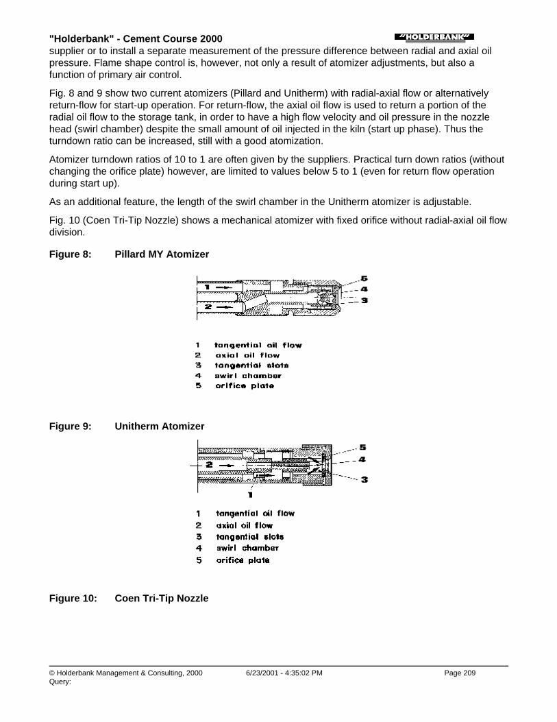
"Holderbank" - Cement Course 2000
© Holderbank Management & Consulting, 2000 6/23/2001 - 4:35:02 PM Page 209Query:
supplier or to install a separate measurement of the pressure difference between radial and axial oilpressure. Flame shape control is, however, not only a result of atomizer adjustments, but also afunction of primary air control.
Fig. 8 and 9 show two current atomizers (Pillard and Unitherm) with radial-axial flow or alternativelyreturn-flow for start-up operation. For return-flow, the axial oil flow is used to return a portion of theradial oil flow to the storage tank, in order to have a high flow velocity and oil pressure in the nozzlehead (swirl chamber) despite the small amount of oil injected in the kiln (start up phase). Thus theturndown ratio can be increased, still with a good atomization.
Atomizer turndown ratios of 10 to 1 are often given by the suppliers. Practical turn down ratios (withoutchanging the orifice plate) however, are limited to values below 5 to 1 (even for return flow operationduring start up).
As an additional feature, the length of the swirl chamber in the Unitherm atomizer is adjustable.
Fig. 10 (Coen Tri-Tip Nozzle) shows a mechanical atomizer with fixed orifice without radial-axial oil flowdivision.
Figure 8: Pillard MY Atomizer
Figure 9: Unitherm Atomizer
Figure 10: Coen Tri-Tip Nozzle

"Holderbank" - Cement Course 2000
© Holderbank Management & Consulting, 2000 6/23/2001 - 4:35:03 PM Page 210Query:
Process Technology / B05 - PT II / C05 - Burners and Flames / Burners and Flames / 2. BURNERS / 2.3 Fuel Oil Atomizers / 2.3.2Mechanical Atomizers with Variable Orifice and Constant Pressure
2.3.2 Mechanical Atomizers with Variable Orifice and Constant Pressure
This type of atomizer employs the adjustable needle valve principle for throughput control. By movingthe needle position, contrary to the above described types, the orifice can be adjusted. Atomizingpressures are in the range of 20 bar. The turndown ratio are also limited. Needle value atomizers aremainly used by FLS for long wet kilns (see Fig. 11). Flame shaping is accomplished by adjusting theneedle position, oil pressure and primary air.
Figure 11: FLS Atomizer (Needle Valve Principe)
1) tangential slots
2) swirl chamber
Process Technology / B05 - PT II / C05 - Burners and Flames / Burners and Flames / 2. BURNERS / 2.3 Fuel Oil Atomizers / 2.3.3Nozzles with Assisted Atomization through Steam or Compressed Air
2.3.3 Nozzles with Assisted Atomization through Steam or Compressed Air
This type of atomizer (Fig. 12) uses steam or compressed air instead of radial oil to create an intenseswirl in front of the orifice plate. The advantage of these atomizers is the higher turndown ratio becauseeven a small amount of oil can be atomized effectively with steam or compressed air. Thedisadvantage of these atomizers is the need for a significant amount of steam or compressed air,which cost money to produce.
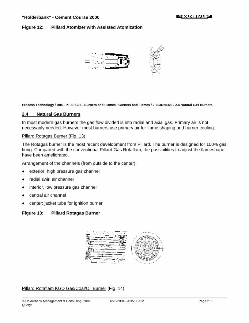
"Holderbank" - Cement Course 2000
© Holderbank Management & Consulting, 2000 6/23/2001 - 4:35:03 PM Page 211Query:
Figure 12: Pillard Atomizer with Assisted Atomization
Process Technology / B05 - PT II / C05 - Burners and Flames / Burners and Flames / 2. BURNERS / 2.4 Natural Gas Burners
2.4 Natural Gas Burners
In most modern gas burners the gas flow divided is into radial and axial gas. Primary air is notnecessarily needed. However most burners use primary air for flame shaping and burner cooling.
Pillard Rotagas Burner (Fig. 13)
The Rotagas burner is the most recent development from Pillard. The burner is designed for 100% gasfiring. Compared with the conventional Pillard Gas Rotaflam, the possibilities to adjust the flameshapehave been ameliorated.
Arrangement of the channels (from outside to the center):
♦ exterior, high pressure gas channel
♦ radial swirl air channel
♦ interior, low pressure gas channel
♦ central air channel
♦ center: jacket tube for ignition burner
Figure 13: Pillard Rotagas Burner
Pillard Rotaflam KGD Gas/Coal/Oil Burner (Fig. 14)

"Holderbank" - Cement Course 2000
© Holderbank Management & Consulting, 2000 6/23/2001 - 4:35:03 PM Page 212Query:
The Rotaflam multipurpose burner is equipped for combined or separate firing of gas, coal and oil.Flame shaping is achieved with separate axial and radial primary air.
Arrangement of the channels (from outside to the center):
♦ axial air
♦ radial swirl-air
♦ single gas channel
♦ pulverized coal channel
♦ central air / flame stabilizer
♦ center: jacket tube with oil atomizing nozzle
Figure 14: Pillard KGD Gas / Coal / Oil Burner
Gyro-Therm Gas Burner (Fig. 15)
The Gyro-Therm burner applies a special flow phenomena to achieve the air/gas mixing. A "processingjet" is generated in a specifically designed nozzle. Experiences with this burner are limited.
Figure 15: Gyro-Therm Gas Burner
KHD Gas Burner (Fig. 16)
This burner has been used in various kilns since a long time. Owing to the principle on which itoperates, it requires a rather high supply pressure (3 - 5 bar) to allow the fuel throughput and theshape of the flame to be varied.

"Holderbank" - Cement Course 2000
© Holderbank Management & Consulting, 2000 6/23/2001 - 4:35:04 PM Page 213Query:
Primary air is not needed for this burner.
Arrangement of the channels (from outside to center):
♦ axial gas channel
♦ center: radial gas
Figure 16: KHD Gas Burner
FLS Gas Burner (Fig. 17)
Flame adjustment is done with this burner using the "needle valve method".
Arrangement of the channels (from outside to center):
♦ primary air (10)
♦ secondary gas (15)
♦ primary gas (14)
♦ center: primary gas with regulating cone (13)
Figure 17: FLS Gas Burner
Process Technology / B05 - PT II / C05 - Burners and Flames / Burners and Flames / 3. FLAMES
3. FLAMES

"Holderbank" - Cement Course 2000
© Holderbank Management & Consulting, 2000 6/23/2001 - 4:35:04 PM Page 214Query:
Process Technology / B05 - PT II / C05 - Burners and Flames / Burners and Flames / 3. FLAMES / 3.1 Prerequisites for the IdealFlame
3.1 Prerequisites for the Ideal Flame
The optimization of the burning has to start with the correct adjustment of the flame.
A look at the effects of poor burning makes this immediately clear:
♦ Unstable coating behavior, particularly in the transition zone, reduces the lining life.
♦ Incomplete burning and a local reducing atmosphere dramatically increase sulfur volatilization andbuild-up of coating in the preheater and in the kiln inlet area. Thus a significantly higher dust cycleis created which shifts the entire temperature profile toward the kiln inlet.
♦ With high CO-formation, secondary combustion forms at the back of the kiln which leads to ringformation.
♦ As a result, the kiln cannot operate at maximum output, the specific heat consumption increasesand the efficiency of the unit drops.
The "ideal" flame can prevent, or at least keep within limits, the operating problems described above.The flame is stable over the entire burn-out distance:
♦ By continually mixing hot secondary air into the burning zone. Therefore combustion can take placein a controlled manner over the entire flame length.
♦ No local temperature peaks are formed.
♦ No local reducing conditions develop over the clinker bed.
♦ Burn-out is complete at the end of the sinter zone.
In addition this "ideal flame" has to be achieved with the lowest possible formation of NOx in theexhaust gas.
Process Technology / B05 - PT II / C05 - Burners and Flames / Burners and Flames / 3. FLAMES / 3.2 Flame Characteristics of theDifferent Burner Systems
3.2 Flame Characteristics of the Different Burner Systems
Process Technology / B05 - PT II / C05 - Burners and Flames / Burners and Flames / 3. FLAMES / 3.2 Flame Characteristics of theDifferent Burner Systems / 3.2.1 Single Channel Burner
3.2.1 Single Channel Burner
Straight burner pipes tend to produce an axial flame without internal recirculation. The heating up ofthe fuel jet to ignition temperatures is predominantly by external recirculation of the hot combustiongases (Fig. 18).
Figure 18: Flame Shape of Single Channel Burner

"Holderbank" - Cement Course 2000
© Holderbank Management & Consulting, 2000 6/23/2001 - 4:35:04 PM Page 215Query:
Effects:
♦ Long sinter zone
♦ Long retention time of the kiln charge in the hot zone and thus high volatilization of alkalis andsulfur (very suitable for the production of low-alkali clinker)
♦ High NOx formation
With a constant primary air ratio, the length of the flame reaches a minimum for a given primary airvelocity. If the velocity is further increased, the primary air jet develops an excessive suction effectwhich results in a reverse flow of flue gases. The recirculating flue gas thins the secondary air so muchthat the flame becomes longer again.
For the recommended range of the specific axial impulsion see chapter 2.1.
However, for optimum flame shaping in response to changing production requirements, burners withadjustable flame (multi channel burners) are to be preferred.
Process Technology / B05 - PT II / C05 - Burners and Flames / Burners and Flames / 3. FLAMES / 3.2 Flame Characteristics of theDifferent Burner Systems / 3.2.2 Multi Channel Burner
3.2.2 Multi Channel Burner
Multi channel burners can produce a divergent flame with internal and external recirculation zones. Theability to change the relationship between axial and radial air provides an important control mechanismfor influencing the flame shape.
A hollow cone flame shape is produced, which can be modified by adjusting the pressure and/orinjection-orifice of the radial and axial air (Fig. 19).
The first generation of three channel burners (e.g. Pillard 3-Channel) has some negative effects on theflame shape, if there is a high content of radial air used. Two different flame zones can appear:
♦ In the first zone with internal recirculation there is intense combustion. Depending on thearrangement of the swirling flow, in this zone coarse fuel particles are spun out of the flame andthen burn quickly in the oxygen-rich atmosphere of the hot secondary air.
♦ In the second, long, instable zone, dominated by external recirculation, burn-out is completed.
Effects:
♦ Peak temperatures in the internal recirculation zone.
♦ With very divergent flames, there are problems with the lining.

"Holderbank" - Cement Course 2000
© Holderbank Management & Consulting, 2000 6/23/2001 - 4:35:05 PM Page 216Query:
♦ CO formation above the clinker bed caused by incomplete burn-out of the extended fuel jet.
♦ Unstable coating formation in a long transition zone, caused by an enlarged unsteady burn-outzone.
♦ Increased NOx formation because of the long retention time of the gasses at high temperatures.
♦ High sulfur volatilization because of the reducing zone above the clinker bed and the long retentiontime at relatively high temperatures.
The new generation of three channel burners (e.g. Pillard Rotaflam and KHD Pyrojet - see also chapter2.2) has been optimized so that these effects are largely avoided. The special arrangement andconstruction of the primary air channels make the internal recirculation zone (IRZ, Fig. 19) longer andmore homogenous. This reduces the length of the burn-out zone with external recirculation. To reduceNOx formation, these burners have been optimized for very low primary air quantities.
For a faster mixing of the primary air with the fuel, these burners have an enlarged flame stabilizer inform of a bluff body in the center.
Figure 19: Flame Shape of New Generation Multi Channel Burner
Effects:
♦ Homogeneous temperature distribution, no excessive temperature peaks.
♦ Low volatilization rate of alkalis and sulfur.
♦ Homogeneous recirculation zone, and therefore low NOx formation.
♦ In some cases the flame is too long. Therefore a rearrangement of the coal channel in between theaxial and radial air (Pillard Rotaflam) is under discussion.
Process Technology / B05 - PT II / C05 - Burners and Flames / Burners and Flames / 3. FLAMES / 3.3 Factors Influencing the Flame
3.3 Factors Influencing the Flame
In most cases the most favorable operation is achieved with a rather short and powerful flame, giving ahigh heat transfer rate to the material bed and a short and stable burning zone.
The flame shape may be optimized during operation by adjusting the following parameters:
Process Technology / B05 - PT II / C05 - Burners and Flames / Burners and Flames / 3. FLAMES / 3.3 Factors Influencing the Flame /3.3.1 Primary Air Momentum
3.3.1 Primary Air Momentum
"Holderbank" - Cement Course 2000
© Holderbank Management & Consulting, 2000 6/23/2001 - 4:35:05 PM Page 217Query:
A shortening of the flame is normally achieved by increasing the injection momentum of the primary air.With existing burners this can be achieved to a limited extent by increasing the radial air anddecreasing axial air correspondingly. With jet burners (KHD) the flame can be optimized by varyingnumber and diameter of jet nozzles and adjusting the jet air pressure.
For burner design recommendations: see chapter 2.2.2.
Process Technology / B05 - PT II / C05 - Burners and Flames / Burners and Flames / 3. FLAMES / 3.3 Factors Influencing the Flame /3.3.2 Position of the Burner in the Kiln
3.3.2 Position of the Burner in the Kiln
One of the most pronounced influence on flame length is the position of the burner tip: Shifting theburner further in the kiln increases the flame length significantly and vice versa.
This is because the turbulence field of the in-flowing secondary air significantly improves the mixing ofthe fuel jet with the air. In planetary cooler kilns this effect is less noticeable as the position of theburner tip is defined by the kiln's internal cooling zone.
Recommendations for burner tip position (except planetary cooler):
♦ Dry kiln: Distance from rotary kiln end to burner tip ≤ 1 m.
♦ Long wet kiln: Distance rotary kiln end - burner tip approx. 1 m or a little more.
If the burner tip is too close to the rotary kiln end, overheating of the nose ring can occur.
Process Technology / B05 - PT II / C05 - Burners and Flames / Burners and Flames / 3. FLAMES / 3.3 Factors Influencing the Flame /3.3.3 Alignment of the Burner in the Kiln
3.3.3 Alignment of the Burner in the Kiln
Basically the burner should be aligned parallel to the kiln axis. In the cold kiln the burner should evenbe pointed slightly upwards, (specially long burners in kilns with planetary coolers), to compensate forthe bending downwards in the hot kiln. If the burner is aligned horizontally (the kiln axis has an angle ofapprox. 3° to the horizontal) as is often seen, the flame tends to reach the material bed. A localreducing atmosphere is created resulting in high sulfur volatilization.
Process Technology / B05 - PT II / C05 - Burners and Flames / Burners and Flames / 3. FLAMES / 3.3 Factors Influencing the Flame /3.3.4 Secondary Air Temperature
3.3.4 Secondary Air Temperature
The secondary air temperature defines, firstly, the ignition behavior of the flame (black plume) and,secondly, the possible flame temperature. Insufficient secondary air temperature has to becompensated by fuel, and this means an increase in the combustion gas quantity and a lengthening ofthe temperature profile. In point of fact, the clinker cooler operation is one of the main factorsinfluencing the flame.
Process Technology / B05 - PT II / C05 - Burners and Flames / Burners and Flames / 3. FLAMES / 3.3 Factors Influencing the Flame /3.3.5 Excess Air

"Holderbank" - Cement Course 2000
© Holderbank Management & Consulting, 2000 6/23/2001 - 4:35:05 PM Page 218Query:
3.3.5 Excess Air
Some excess air is required for complete combustion. The optimum value for excess air to maintainthe shortest possible sinter zone is about 10% (equal to 2% O2 at kiln inlet). Burning at a too lowexcess air factor increases the burning time and hence the flame length. This creates a reducingatmosphere which increases sulfur volatility thus leading eventually to clogging problems in thepreheating zone. If the excess air is significantly higher than the optimum value, the temperature profileis extended again because of a too low flame. This results in an insufficient temperature gradienttowards the material bed and a longer sinter zone. For this reason, for example, the secondary firingrate for Air-Through systems is restricted to about 25 ± 5%.
Process Technology / B05 - PT II / C05 - Burners and Flames / Burners and Flames / 3. FLAMES / 3.3 Factors Influencing the Flame /3.3.6 Interaction Flame - Material Bed
3.3.6 Interaction Flame - Material Bed
As the heat transfer from the flame to the material bed in the sinter zone is almost entirely throughradiation, the key factors affecting heat transfer are the temperature and the emissivity of the flame. Ifradiation is reduced by a dusty kiln atmosphere, a long drawn-out temperature profile with long sinterzone is produced. In this situation, the clinker dust is overheated in the flame and often deposited inthe transition zone or even further upstream the kiln in the form of a clinker ring. Ways to counter thiseffect include all those measures which serve to improve clinker granulation (short and hot flame,different raw mix design).
Process Technology / B05 - PT II / C05 - Burners and Flames / Burners and Flames / 3. FLAMES / 3.3 Factors Influencing the Flame /3.3.7 Burner Dimensions
3.3.7 Burner Dimensions
Basically the burner must be of the right dimensions for nominal operation. This is observed particularlyfor burners in kilns with precalcination.
Oversized burner nozzles have to be operated with unfavorable primary air settings (either too highprimary air content or too low primary air speed) and should be adjusted for nominal operation.
Process Technology / B05 - PT II / C05 - Burners and Flames / Burners and Flames / 3. FLAMES / 3.3 Factors Influencing the Flame /3.3.8 Pulverized Coal Characteristics
3.3.8 Pulverized Coal Characteristics
♦ Volatile content:
♦ The combustion time of pulverized coal increases as the volatile content decreases, therefore lowvolatile coal has a longer burning time and ignition distance than bituminous coal.
♦ Grinding fineness:
♦ The burning time of a coal dust grain increases approx. with the square of its diameter. Thecombustion time of a grain of coal increases as its volatile content decreases. Thus, low volatilecoal must be ground more finely in order to burn within the desired time, e.g. in order to producethe desired flame length.
♦ Recommendations for optimum grinding fineness:see paper "Firing Systems - Handling and Preparation of Noble Fuels".
♦ Ash content:

"Holderbank" - Cement Course 2000
© Holderbank Management & Consulting, 2000 6/23/2001 - 4:35:06 PM Page 219Query:
♦ A high content of ballast material (ash) has a retarding effect on the burning time caused by thereduced coal dust concentration and the lower flame temperatures as a result of the heatabsorption of the ballast material.
♦ Rate of swelling:
♦ The higher the expansion of the coal grain during heating in the flame, the shorter the burning time.Coal types with high density expand / swell less. Therefore petrol coks has to be ground finer toreach the same combustion time as regular coal.
Process Technology / B05 - PT II / C05 - Burners and Flames / Burners and Flames / 3. FLAMES / 3.3 Factors Influencing the Flame /3.3.9 Fuel Oil Flame Adjustments
3.3.9 Fuel Oil Flame Adjustments
A faster burn out of the fuel oil can be achieved by lowering the oil viscosity / increasing the oiltemperature (recommendations for optimum oil temperature: see paper "Firing Systems - Handling andPreparation of Noble Fuels") or by better atomization (see chapter 2.3).
Process Technology / B05 - PT II / C05 - Burners and Flames / Burners and Flames / 3. FLAMES / 3.3 Factors Influencing the Flame /3.3.10 Natural Gas Flame Adjustments
3.3.10 Natural Gas Flame Adjustments
The main requirement with natural gas burners is the possibility of producing a reverse flow zone in thecenter of the flame in order to achieve locally a reducing atmosphere where the hydrocarbon moleculesagglomerate to larger chains. This is necessary to increase the emissivity of the gas flame, aprerequisite for heat transfer in the sintering zone.
Adjusting the shape of the flame visually is almost impossible, because clearly defined flame contoursare hardly recognizable. Optimization of the flame shape should be done following the combustionindicators (see chapter 3.5).
Process Technology / B05 - PT II / C05 - Burners and Flames / Burners and Flames / 3. FLAMES / 3.3 Factors Influencing the Flame /3.3.11 Combined Firing of Different Fuels
3.3.11 Combined Firing of Different Fuels
When firing two different fuels at the same time, the higher volatile fuel tends to burn more rapidly. thisreduces the oxygen content so that the remaining fuel burns further to the back of the kiln.
However, a small amount of high volatile fuel can also have a positive effect on the flame, because itaccelerates the ignition and burning of the other fuel.
In extreme cases, two separate burning zones are created. It is therefore important to improve theburning time of the less volatile fuel (e.g. by adjusting the fineness of grinding for coal).
Process Technology / B05 - PT II / C05 - Burners and Flames / Burners and Flames / 3. FLAMES / 3.3 Factors Influencing the Flame /3.3.12 Oxygen Enrichment
3.3.12 Oxygen Enrichment
By adding oxygen to the combustion air, the flame temperature can be increased significantly. At thesame time the specific exhaust gas quantity is lowered. This decreases the energy losses of theexhaust gas and allows to increase the production capacity of the kiln.
Practically feasible is the increase of O2 in the combustion air by 2 - 3% (from 21% to 24%).

"Holderbank" - Cement Course 2000
© Holderbank Management & Consulting, 2000 6/23/2001 - 4:35:06 PM Page 220Query:
Disadvantages are the higher NOx formation, the lower cooler efficiency for planetary coolers and theoxygen costs.
Process Technology / B05 - PT II / C05 - Burners and Flames / Burners and Flames / 3. FLAMES / 3.4 Combustion Indicators
3.4 Combustion Indicators
One of the main problems in the evaluation of the flame is that, in the rotary kiln, it is only possible toobserve the flame visually to a limited extent. On closer consideration, however, there are a number ofindicators which can provide much more information about the quality of the flame than can beobtained from simple visual observation.
In the following, the most important operation indicators (combustion indicators) with direct relation tofiring parameters are discussed:
♦ Clinker quality (free lime, liter weight)
♦ Burning zone temperature (pyrometer, NOx, amps)
♦ Coating formation (indicated by kiln shell temperature profile)
♦ Exhaust gas composition (CO, O2)
♦ Kiln inlet temperature
♦ Volatilization of circulating elements (hot meal analysis, encrustations in the preheater)
Process Technology / B05 - PT II / C05 - Burners and Flames / Burners and Flames / 3. FLAMES / 3.4 Combustion Indicators / 3.4.1Clinker Quality
3.4.1 Clinker Quality
There exists a close interdependence between sintering zone temperature, granulometry, free lime andliterweight of the clinker. The correlation of these parameters is to a high degree influenced by theflame shape. Fig. 20 shows an example, where by flame optimization, the literweight for the requiredfree lime could be lowered. In other words, for the required clinker quality (free lime), burning could bedone less hard (liter weight).
Burning less hard leads to substantial savings of energy and refractories.
Figure. 20: Correlation between Free Lime Content and Literweight with Two DifferentOperating Conditions
When modifying the burner settings, the correlation of the parameters shown above has to be closely

"Holderbank" - Cement Course 2000
© Holderbank Management & Consulting, 2000 6/23/2001 - 4:35:06 PM Page 221Query:
recorded before and after any change to the burner in order to draw the relevant information foroptimum burner settings.
Process Technology / B05 - PT II / C05 - Burners and Flames / Burners and Flames / 3. FLAMES / 3.4 Combustion Indicators / 3.4.2Sintering Zone Temperature
3.4.2 Sintering Zone Temperature
Information about the sintering zone temperature can be obtained by:
♦ Measuring the clinker bed temperature under the flame using a radiation pyrometer.
♦ Measuring the NOx concentration in the exhaust gas.
♦ Measuring the inclination of the kiln charge using a tallumeter.
♦ Measuring the kiln drive power consumption (Amps or kW) - (only reliable in some cases).
It has to be noted, that all the above mentioned measurements do not supply absolute but ratherrelative temperature indications and that the NOx-level is also highly depending on the flamecharacteristics (see chapter 3.6).
Process Technology / B05 - PT II / C05 - Burners and Flames / Burners and Flames / 3. FLAMES / 3.4 Combustion Indicators / 3.4.3Coating Formation
3.4.3 Coating Formation
The length of the sinter zone and transition zone gives a guide to the length and temperature profile ofthe flame. Ring formation can indicate poor combustion, incorrect burner setting, or insufficient fuelpreparation (coal not fine enough or poor oil atomizing).
Coating formation can be determined indirectly, by measuring the temperature profile of the kiln shell.
The influence of burner adjustments on coating formation can be checked by recording the kiln shelltemperature profile before and after any change to burner settings.
Process Technology / B05 - PT II / C05 - Burners and Flames / Burners and Flames / 3. FLAMES / 3.4 Combustion Indicators / 3.4.4Exhaust Gas Analysis
3.4.4 Exhaust Gas Analysis
Exhaust gas analysis at kiln inlet supplies valuable information on the completeness of the combustion.Due to factors such as fluctuations in fuel supply and quality, generally a too high O2 level would berequired for 0% CO. Usually the kiln is set to an O2 level at kiln inlet, at which < 500 ppm CO isproduced. A thus required O2 level in excess of 2.5% would indicate combustion problems.
Too high CO levels do not only cause energy losses but do also increase Sulfur volatilization and maycause Sulfur rings and cloggings in the cyclones.
Process Technology / B05 - PT II / C05 - Burners and Flames / Burners and Flames / 3. FLAMES / 3.4 Combustion Indicators / 3.4.5Kiln Inlet Temperature
3.4.5 Kiln Inlet Temperature
With preheater kilns, the kiln inlet temperature (= back end temperature) supplies information on flamelength and retarded combustion. The target is to have the kiln inlet temperature as low as possible. Kilninlet temperatures in excess of 1100°C need improvement of the firing system.
Process Technology / B05 - PT II / C05 - Burners and Flames / Burners and Flames / 3. FLAMES / 3.4 Combustion Indicators / 3.4.6

"Holderbank" - Cement Course 2000
© Holderbank Management & Consulting, 2000 6/23/2001 - 4:35:06 PM Page 222Query:
Volatilization of Circulating Elements
3.4.6 Volatilization of Circulating Elements
The flame has an important influence on the volatilization of the circulation elements, especifically onSulfur. This is governed by factors such as retention time of the material in the hot zone (flame length)and local or general reducing atmosphere including the presence of oversize fuel particles in thematerial bed (Fig. 21).
Figure 21: Influence of Temperature and O2 Concentration on Sulfur Volatility
To assess the degree of volatilization of the circulating elements, the enrichment of SO3, CI and K2O inthe hot meal has to be measured before and after any change to the firing system.
Process Technology / B05 - PT II / C05 - Burners and Flames / Burners and Flames / 3. FLAMES / 3.5 NOx Formation
3.5 NOx Formation
NOx formation is dominated as well by peak temperatures as by the amount of air entrained into theprimary fuel jet at ignition. NOx reduction measures are deduced essentially from these facts asfollows:
♦ Low primary air ratio
♦ Flame front near the burner (short ignition distance)
♦ Flame shaping with the aim to avoid high peak temperatures with at the same time shorter flame
♦ Lower burning temperatures (free lime, raw mix)
The minimum technically achievable NOx emission with measures related to the rotary kiln burner arein the order of magnitude of 800 to 1'000 mg/Nm3 (dry basis). Further reduction of NOx requiresadditional secondary measures such as staged combustion (air / fuel staging, reburning) at theprecalciner or NH3 injection.
For more details on NOx formations see paper "State of Technology of Rotary Kiln Burners".
Process Technology / B05 - PT II / C05 - Burners and Flames / Burners and Flames / 3. FLAMES / 3.6 Flame Adjustment Procedure
3.6 Flame Adjustment Procedure
1) Follow the operating instruction of the supplier for a medium flame setting.
2) Wait until kiln is stable before undertaking any adjustment.
3) Progressively adjust parameters (axial/radial air, oil pressure, gas pressure) to get required flame.
"Holderbank" - Cement Course 2000
© Holderbank Management & Consulting, 2000 6/23/2001 - 4:35:07 PM Page 223Query:
♦ Cautions:
• axial air outside channel also serves to cool the burner pipe; keep alwaysmin.8% of total primary air
• watch continuously the corresponding combustion indicators
♦ The kiln reacts slowly to any change. It may take up to a few days to reach stable runningconditions again. It is therefore useless to try to adjust a flame within one shift!
4) It is not recommended to operate the kiln with the shortest possible flame. A safety margin foradjustment in both directions should be maintained for control of burning zone disturbance.
NOx Emission: In some countries with severe regulations, the NOx emission might be in a near futurethe most important parameter for flame adjustment.
Process Technology / B05 - PT II / C05 - Burners and Flames / Burners and Flames / 4. SECONDARY FIRING / PRECALCINER
4. SECONDARY FIRING / PRECALCINER
The burning conditions for a secondary firing or precalciner burner are quite different from the kilnfiring:
♦ In most cases the combustion takes place in a exhaust gas + air mixture instead of pure air.
♦ Combustion takes place in a very dusty atmosphere.
♦ Temperature range of 1000°C instead of 2000°C.
Due to the poor burning conditions, incomplete combustion is quite common in precalciners. BesideCO, coal firing produces carbon skeletons and also CH4, which both cannot be traced by COmeasuring equipment. Further signs for incomplete combustion are:
♦ Higher gas temperature at bottom cyclone outlet than at precalciner outlet.
♦ Only moderate drop of the gas temperature over the two lowermost cyclone stages.
Both indication an after-burning within the preheater. This results in increased exhaust gastemperature and heat consumption.
Improvement Measures:
♦ Avoiding fluctuations of the fuel feed.
♦ Grinding the coal to the required fineness.
♦ Providing enough gas retention time in the precalciner. As a rule of thumb for coal firing:
• gas retention time = 2 to 3 sec.
• (kiln capacity [t/d]) / (precalciner volume inside lining [m3] ) = 7 ± 2 t/m3 d
Process Technology / B05 - PT II / C05 - Burners and Flames / Burners and Flames / 5. LIST OF REFERENCES
5. LIST OF REFERENCES
1) "Firing Systems"VA 82/4898/E
2) "Flames and Burners"VA 93/4056/E

"Holderbank" - Cement Course 2000
© Holderbank Management & Consulting, 2000 6/23/2001 - 4:35:07 PM Page 224Query:
3) "State of Technology of Rotary Kiln Burners"F. Schneider, PT 96/14078/E
4) W.L. van de Kamp / J.P. SmartIFRF Research Report CEMFLAM1"The effect of burner design and operation and fuel type of cement kiln flames"
Process Technology / B05 - PT II / C05 - Burners and Flames / Burners and Flames / 6. ANNEX
6. ANNEX
Process Technology / B05 - PT II / C05 - Burners and Flames / Burners and Flames / 6. ANNEX / 6.1 Formulas and Definitions for theCalculation of Burner Momentum and Swirl Number
6.1 Formulas and Definitions for the Calculation of Burner Momentum and Swirl Number
Process Technology / B05 - PT II / C05 - Burners and Flames / Burners and Flames / 6. ANNEX / 6.1 Formulas and Definitions for theCalculation of Burner Momentum and Swirl Number / 6.1.1 Primary Air / Combustion Air:
6.1.1 Primary Air / Combustion Air:
Kiln heat consumption Q [MJ/kgcli]
Min. combustion air Amin. 0.26 x q [Nm3/kgcli] Good approximation forconventional fuels
Total combustion air A n x Amin. [Nm3/kgcli] n = excess air factor, n>1
Excess combustion air Amin. x (n-1) [Nm3/kgcli]
Primary air ratio Expressed in %Amin.
[%A min.]
Note:
In order to get lower primary air ratio figures, burner suppliers usually relate primary air ratio to totalcombustion air.
Process Technology / B05 - PT II / C05 - Burners and Flames / Burners and Flames / 6. ANNEX / 6.1 Formulas and Definitions for theCalculation of Burner Momentum and Swirl Number / 6.1.2 Burner Geometry:
6.1.2 Burner Geometry:
Following burner geometry calculations are based on the list of symbols and units stated below:
ri Burner channel radius of channel I [m]
reg. i Equivalent channel radius of channel I [m]
Gx Axial momentum [N]
Gx.i Axial momentum of channel I [N]
Gax Specific axial momentum [N/MW]

"Holderbank" - Cement Course 2000
© Holderbank Management & Consulting, 2000 6/23/2001 - 4:35:07 PM Page 225Query:
Gax
Gt Tangential momentum [N]
Mi Mass flow through channel I [kg/s]
Qfuel Fuel heat input [MW]
Sb Burner swirl number [-]
vi.ax Axial velocity in channel I [m/s]
vsw.tan Tangential velocity on swirling channel [m/s]
Figure A: Typical Burner Geometry
Process Technology / B05 - PT II / C05 - Burners and Flames / Burners and Flames / 6. ANNEX / 6.1 Formulas and Definitions for theCalculation of Burner Momentum and Swirl Number / 6.1.3 Mono Channel Burner:
6.1.3 Mono Channel Burner:
Total specific axial momentum through burner [N/MW]:
×=
+
MWN
Q
vMG
fuel
trctrax
Process Technology / B05 - PT II / C05 - Burners and Flames / Burners and Flames / 6. ANNEX / 6.1 Formulas and Definitions for theCalculation of Burner Momentum and Swirl Number / 6.1.4 Multi Channel Burner:
6.1.4 Multi Channel Burner:
Total specific axial momentum through burner [N/MW]:
( )( )
×+×+×
= +
MWN
Q
vMvMvMG
fuel
axaxaxtrctraxswswax
,,
Burner Swirl Number:
[ ] [ ][ ] [ ]( ) [ ]−
×
×
Σ=
mRadiusChannelsticalCharacteriNMomentumAxial
mRadiusSwirlsticalCharacteriNMomentumTangentialnumberSwirl
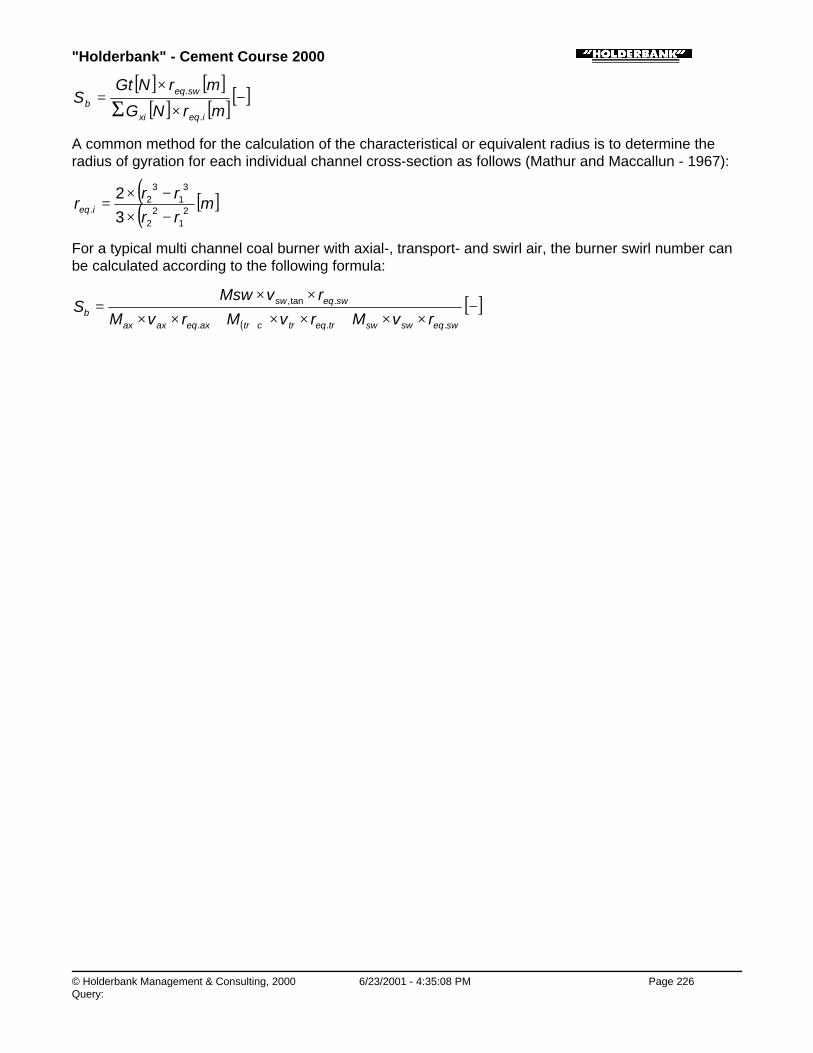
"Holderbank" - Cement Course 2000
© Holderbank Management & Consulting, 2000 6/23/2001 - 4:35:08 PM Page 226Query:
[ ] [ ][ ] [ ][ ]−
×
×= Σ mrNG
mrNGtS
ieqxi
sweqb
.
.
A common method for the calculation of the characteristical or equivalent radius is to determine theradius of gyration for each individual channel cross-section as follows (Mathur and Maccallun - 1967):
( )( )[ ]m
rrrr
r ieq 21
22
31
32
.32
−×−×
=
For a typical multi channel coal burner with axial-, transport- and swirl air, the burner swirl number canbe calculated according to the following formula:
( )[ ]−
××+××+××
××=
+ sweqswswtreqtrctraxeqaxax
sweqswb rvMrvMrvM
rvMswS
...
.tan,
"Holderbank" - Cement Course 2000
© Holderbank Management & Consulting, 2000 6/23/2001 - 4:35:08 PM Page 227Query:
Process Technology / B05 - PT II / C06 - Combustion Engineering
C06 - Combustion Engineering
"Holderbank" - Cement Course 2000
© Holderbank Management & Consulting, 2000 6/23/2001 - 4:35:09 PM Page 228Query:
Process Technology / B05 - PT II / C06 - Combustion Engineering / Combustion, Gasflows and Gas Composition
Combustion, Gasflows and Gas CompositionA. ObristVA 89/5584/E
1. INTRODUCTION
2. COMBUSTION
2.1 Basic Relations and Definitions
2.2 Calorific Value
2.3 Combustion Calculations
3. GAS FROM RAW MATERIAL
3.1 Gases from Dry Raw Meal
3.2 Water from Wet Raw Meal or from Raw Slurry
4. KILN GAS
4.1 Measurement of Exhaust Gas Composition
4.2 Immediate Calculations from Gas Composition
4.3 Calculation of Exhaust Gas Quantities
4.4 Calculation of the CO2 Content of Cement Kiln Exhaust Gas
5. FALSE AIR INVESTIGATIONS
5.1 Introduction
5.2 Evaluation
5.3 Example of an Investigation
"Holderbank" - Cement Course 2000
© Holderbank Management & Consulting, 2000 6/23/2001 - 4:35:09 PM Page 229Query:
SUMMARY
In context with gas measurements on a cement kiln there are important numerical relations which mustbe understood.
Such numerical relations involve the following subjects:
♦ Fuel properties, calorific value
♦ Raw meal properties
♦ Combustion calculations
♦ Gas composition
♦ Gas properties
♦ Gas quantities
♦ False air
Calculations can be done with complete, exact formulas but sometimes also by using approximations.Approximations are never 100% precise but often sufficient for practical purposes. Important, basicapproximations given in this chapter are e.g.:
♦ Min. combustion air = Amin ≈ 0.26 Nm3/MJ
♦ Min. combustion gas = Vmin ≈ 0.28 Nm3/MJ
The exhaust gas of a cement kiln consists of:
♦ Gas from raw meal
♦ Gas from combustion
♦ Excess air and false air
♦ Water from slurry or raw meal
By considering the above contributions the exhaust gas quantity of a kiln can be calculated.
This method of calculation and many other relations are given in this chapter.
Process Technology / B05 - PT II / C06 - Combustion Engineering / Combustion, Gasflows and Gas Composition / 1.INTRODUCTION
1. INTRODUCTION
Once, in the Greenfield cement factory, they wanted to do a few measurements on their kiln system,which seemed to run at its capacity limit. The specialist who was in charge of these measurementswanted to know the actual gas flows in the kiln system. Unfortunately, a few years ago, the designersof the Greenfield kiln had to fight with some difficult space problems when they had to plan the layoutof the gas ducts in the narrow space. They never had considered that somebody would have to takeflow measurements in this ductwork. The shape of the gas ducts was far away from the „ideal, longstraight tube“ for a precise flow measurement.
After a hard job within the hot areas of the gas ducts the specialist realized that his results from thepitot tube measurement was still not as precise as he had imagined. He therefore started to think abouthis problem. Maybe, there was another method to come to a result? Obviously gas flow has somethingto do with the fuel combustion and also raw meal produces some gas. So, why not calculate the gas

"Holderbank" - Cement Course 2000
© Holderbank Management & Consulting, 2000 6/23/2001 - 4:35:09 PM Page 230Query:
from other parameters such as fuel quantity and raw meal? And wouldn’t it be possible to calculatealso the gas composition? But where do I find the necessary relations and formulas?
With this kind of thoughts in mind the specialist in the Greenfield plant was about to use the paper onhand, and finally to do a more interesting and effective job.
Process Technology / B05 - PT II / C06 - Combustion Engineering / Combustion, Gasflows and Gas Composition / 2. COMBUSTION
2. COMBUSTION
Process Technology / B05 - PT II / C06 - Combustion Engineering / Combustion, Gasflows and Gas Composition / 2. COMBUSTION /2.1 Basic Relations and Definitions
2.1 Basic Relations and Definitions
Process Technology / B05 - PT II / C06 - Combustion Engineering / Combustion, Gasflows and Gas Composition / 2. COMBUSTION /2.1 Basic Relations and Definitions / 2.1.1 Combustion
2.1.1 Combustion
Combustion of fuels is a chemical reaction of fuel with oxygen (O2) according to the general scheme:
FUEL + OXYGEN → COMBUSTION PRODUCTS
(CO2, H2O, SO2, Ash)
Combustion reactions usually go through intermediate steps where some intermediate products mayoccur. However after complete combustion (total oxidation) the resulting combustion products are ofextremely simple nature because complete combustion always ends at only 3(!) simple gas molecules,namely CO2, H2O and SO2.
The overall combustion reactions can therefore be characterized by three very simple combustionequations:
C + O2 → CO2
2H + ½ O2 → H2O
S + O2 → SO2
Process Technology / B05 - PT II / C06 - Combustion Engineering / Combustion, Gasflows and Gas Composition / 2. COMBUSTION /2.1 Basic Relations and Definitions / 2.1.2 Air
2.1.2 Air
Oxygen for combustion of fuels is taken from the air. For the considerations within this chapter thecomposition of the dry air can be simplified (neglecting trace gases) as follows:

"Holderbank" - Cement Course 2000
© Holderbank Management & Consulting, 2000 6/23/2001 - 4:35:09 PM Page 231Query:
OXYGEN (O2) 21.0 Vol%
NITROGEN (N2) 79.0 Vol%
AIR 100.0 Vol%
According to the local climate air contains some water vapor, e.g. 2 Vol% at 20°C and 80% relativehumidity.
Process Technology / B05 - PT II / C06 - Combustion Engineering / Combustion, Gasflows and Gas Composition / 2. COMBUSTION /2.1 Basic Relations and Definitions / 2.1.3 Normal Conditions
2.1.3 Normal Conditions
„Normal conditions“ for gases are defined as:
♦ Pressure = 1.0133 bar = 760 Torr
♦ Temperature = 0°C = 273.16°K
By the above conditions, the Nm3 (Normal-cubicmeter) is defined which is used as unit for gasquantities.
Note:
1) The „normal conditions“ refer to the average atmospheric pressure at sea level (Fig. 1 at altitude =0 m) and at the zero point of the Celsius temperature scale (0°C).
2) There is a similar definition of „standard conditions“ (USA) which refers to the 60°F point of theFahrenheit temperature scale (30 inch Hg = 1.016 bar, 60°F = 15.6°C). Unfortunately theseconditions are not equal to the „normal conditions“ in the metric system.
Fig. 1 Average Barometric Pressure in Function of Altitude
Process Technology / B05 - PT II / C06 - Combustion Engineering / Combustion, Gasflows and Gas Composition / 2. COMBUSTION /2.1 Basic Relations and Definitions / 2.1.4 Kmol and Ideal Gas
2.1.4 Kmol and Ideal Gas
To characterize the quantity of substances in context with chemical reactions the unit kmol is used.

"Holderbank" - Cement Course 2000
© Holderbank Management & Consulting, 2000 6/23/2001 - 4:35:10 PM Page 232Query:
One kmol means a certain number of molecules (Avogadro’s constant = 6.02 x 1026/kmol).
If the molecular weight of a compound is taken in kg it equals to 1 kmol of this substance. For example:The molecular weight of CO2 is 44. Therefore 44 kg of CO2 are equal to 1 kmol (which contains 6.02 x1026 molecules) of CO2.
One of the basic relations of chemistry and thermodynamics says that a certain number of 1 kmol ofany gas molecules takes always the same volume (at constant pressure and temperature). Theformula of the gas molecules does not have any influence on their volume in gaseous state.
To say this more precisely it must be added that this applies only for ideal gases. Gases at low partialpressures and at temperatures above the critical point can be considered as ideal gases. All gasesoccurring in context with this chapter can be considered as ideal gases with sufficient accuracy(approx. 0.1%).
This fact can be used by the following quantitative relationship:
♦ 1 kmol of an ideal gas takes a volume of 22.4 m3 at normal conditions (1.0133 bar, 0°C)
Or in short form:
♦ 1 kmol of gas = 22.4 Nm3
Note that even H2O and CO2 behave nearly like ideal gases as long as they occur in gas mixtures atlow partial pressures.
Process Technology / B05 - PT II / C06 - Combustion Engineering / Combustion, Gasflows and Gas Composition / 2. COMBUSTION /2.1 Basic Relations and Definitions / 2.1.5 Conversion of the Volume of Ideal Gases
2.1.5 Conversion of the Volume of Ideal Gases
Ideal gases or mixtures of ideal gases behave according to the fundamental equation:
♦ pv = RT(p = absolute pressure, V = volume, R = gas-constant, T = absolute temperature)
Therefore, volume conversions from condition 1 to condition 2 can be done easily by means of theratios of absolute temperature [K] and absolute pressure as follows:
×
×=
1
2
2
112 T
TPP
VV
Example: Convert V1 = 1 m3 at 350°C (623.16 K) and 0.9 bar to normal conditions:
332 389.0
K 623.16K 273.16
bar 1.0133bar 0.9
1 NmmV =
×
=
This type of calculation is frequently used for practical gas flow calculations. However, for theconsiderations within this paper it will not be required in the following.
Process Technology / B05 - PT II / C06 - Combustion Engineering / Combustion, Gasflows and Gas Composition / 2. COMBUSTION /2.1 Basic Relations and Definitions / 2.1.6 Minimum Air and Air Factor
2.1.6 Minimum Air and Air Factor
To perform a complete combustion a theoretical minimum amount of oxygen O2 min) is required,

"Holderbank" - Cement Course 2000
© Holderbank Management & Consulting, 2000 6/23/2001 - 4:35:10 PM Page 233Query:
depending on the type of fuel. The corresponding minimum quantity of air is called Amin:
][21.0min 32
min NmO
A =
Practically a combustion requires always slightly more air than the theoretical minimum Amin in order toavoid local lack of O2 and unburnt products. The air factor „n“ is defined as the following ratio:
][min
−=AA
n
A is the effective air quantity, n must be always higher than 1 in order to maintain completecombustion.
Process Technology / B05 - PT II / C06 - Combustion Engineering / Combustion, Gasflows and Gas Composition / 2. COMBUSTION /2.2 Calorific Value
2.2 Calorific Value
Process Technology / B05 - PT II / C06 - Combustion Engineering / Combustion, Gasflows and Gas Composition / 2. COMBUSTION /2.2 Calorific Value / 2.2.1 Gross and Net Calorific Value (CV)
2.2.1 Gross and Net Calorific Value (CV)
The calorific value of a fuel sample is measured in a bomb calorimeter. The fuel sample and a surplusof oxygen are ignited in the bomb and after combustion the amount of heat is measured. The bomb isthereby cooled to room temperature level.
By cooling the calorimeter the water vapor is condensed and therefore the heat of water condensation(2450 kJ/kg H2O at 20°C) is included in the resulting heat.
The direct result (amount of heat) obtained from the calorimeter is therefore always the so called grosscalorific value CVgross (in German: oberer Heizwert, Brennwert, Ho) of the fuel.
The gross value, however, is not very significant for common technical applications because the effectof water condensation does usually not occur. Therefore the net calorific value (in German: untererHeizwert, Hu) value is calculated by subtracting the heat of condensation, as follows:
CVnet = CVgross - (water in combustion products) x 2450 [kJ/kg fuel]
The water in combustion products is calculated as follows:
H2O = H2Ofuel + 9 x Hfuel [kg/kg fuel]
↑hydrogen in fuel [kg/kg fuel]
Important Note: Within this chapter and also within the cement course chapter on Heat Balances thenet calorific value is used as reference. Unless otherwise noted, fuel energy or fuel heat always refersto net calorific value.
Process Technology / B05 - PT II / C06 - Combustion Engineering / Combustion, Gasflows and Gas Composition / 2. COMBUSTION /2.2 Calorific Value / 2.2.2 Calculation of CV
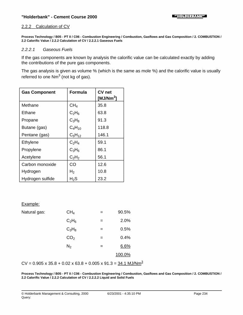
"Holderbank" - Cement Course 2000
© Holderbank Management & Consulting, 2000 6/23/2001 - 4:35:10 PM Page 234Query:
2.2.2 Calculation of CV
Process Technology / B05 - PT II / C06 - Combustion Engineering / Combustion, Gasflows and Gas Composition / 2. COMBUSTION /2.2 Calorific Value / 2.2.2 Calculation of CV / 2.2.2.1 Gaseous Fuels
2.2.2.1 Gaseous Fuels
If the gas components are known by analysis the calorific value can be calculated exactly by addingthe contributions of the pure gas components.
The gas analysis is given as volume % (which is the same as mole %) and the calorific value is usuallyreferred to one Nm3 (not kg of gas).
Gas Component Formula CV net[MJ/Nm3]
Methane CH4 35.8
Ethane C2H6 63.8
Propane C3H8 91.3
Butane (gas) C4H10 118.8
Pentane (gas) C5H12 146.1
Ethylene C2H4 59.1
Propylene C3H6 86.1
Acetylene C2H2 56.1
Carbon monoxide CO 12.6
Hydrogen H2 10.8
Hydrogen sulfide H2S 23.2
Example:
Natural gas: CH4 = 90.5%
C2H6 = 2.0%
C3H8 = 0.5%
CO2 = 0.4%
N2 = 6.6%
100.0%
CV = 0.905 x 35.8 + 0.02 x 63.8 + 0.005 x 91.3 = 34.1 MJ/Nm3
Process Technology / B05 - PT II / C06 - Combustion Engineering / Combustion, Gasflows and Gas Composition / 2. COMBUSTION /2.2 Calorific Value / 2.2.2 Calculation of CV / 2.2.2.2 Liquid and Solid Fuels
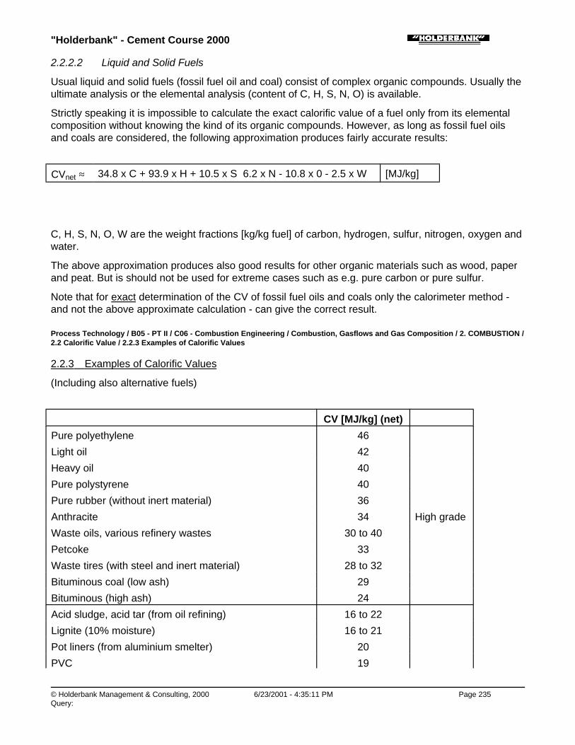
"Holderbank" - Cement Course 2000
© Holderbank Management & Consulting, 2000 6/23/2001 - 4:35:11 PM Page 235Query:
2.2.2.2 Liquid and Solid Fuels
Usual liquid and solid fuels (fossil fuel oil and coal) consist of complex organic compounds. Usually theultimate analysis or the elemental analysis (content of C, H, S, N, O) is available.
Strictly speaking it is impossible to calculate the exact calorific value of a fuel only from its elementalcomposition without knowing the kind of its organic compounds. However, as long as fossil fuel oilsand coals are considered, the following approximation produces fairly accurate results:
CVnet ≈ 34.8 x C + 93.9 x H + 10.5 x S 6.2 x N - 10.8 x 0 - 2.5 x W [MJ/kg]
C, H, S, N, O, W are the weight fractions [kg/kg fuel] of carbon, hydrogen, sulfur, nitrogen, oxygen andwater.
The above approximation produces also good results for other organic materials such as wood, paperand peat. But is should not be used for extreme cases such as e.g. pure carbon or pure sulfur.
Note that for exact determination of the CV of fossil fuel oils and coals only the calorimeter method -and not the above approximate calculation - can give the correct result.
Process Technology / B05 - PT II / C06 - Combustion Engineering / Combustion, Gasflows and Gas Composition / 2. COMBUSTION /2.2 Calorific Value / 2.2.3 Examples of Calorific Values
2.2.3 Examples of Calorific Values
(Including also alternative fuels)
CV [MJ/kg] (net)
Pure polyethylene 46
Light oil 42
Heavy oil 40
Pure polystyrene 40
Pure rubber (without inert material) 36
Anthracite 34 High grade
Waste oils, various refinery wastes 30 to 40
Petcoke 33
Waste tires (with steel and inert material) 28 to 32
Bituminous coal (low ash) 29
Bituminous (high ash) 24
Acid sludge, acid tar (from oil refining) 16 to 22
Lignite (10% moisture) 16 to 21
Pot liners (from aluminium smelter) 20
PVC 19

"Holderbank" - Cement Course 2000
© Holderbank Management & Consulting, 2000 6/23/2001 - 4:35:11 PM Page 236Query:
PVC 19
Palm nut shells (10% moisture) 19 Mediumgrade
Pressed olive cake 18
Dried peat (10% moisture) 18
Fuller earth (from oil refining) 13 to 18
Dried wood, bark, saw dust (10% moisture) 16
Rice husks (10% moisture) 16
Shredder wastes 15
RDF (from domestic refuse, 10% moisture) 15
Cardboard, paper (air dry) 15 Low grade
Dried sewage sludge (10% moisture) 10
Domestic refuse (30% moisture) 8.5
Pure iron (heat of oxidation!, occurs e.g. in waste tires) 7.5
Process Technology / B05 - PT II / C06 - Combustion Engineering / Combustion, Gasflows and Gas Composition / 2. COMBUSTION /2.3 Combustion Calculations
2.3 Combustion Calculations
Process Technology / B05 - PT II / C06 - Combustion Engineering / Combustion, Gasflows and Gas Composition / 2. COMBUSTION /2.3 Combustion Calculations / 2.3.1 Exact Calculations
2.3.1 Exact Calculations
The following calculations are based on the combustion equations (see 2.1.1) and some basicrelations.
To demonstrate the calculation method, the simple example of combustion of pure carbon is given asexample.
Process Technology / B05 - PT II / C06 - Combustion Engineering / Combustion, Gasflows and Gas Composition / 2. COMBUSTION /2.3 Combustion Calculations / 2.3.1 Exact Calculations / 2.3.1.1 Combustion of Pure Carbon (C)
2.3.1.1 Combustion of Pure Carbon (C)
The combustion of 1 kg of pure carbon (C) without any excess air (n = 1) is considered.
The combustion equation and the corresponding weights and volumes are as follows:
C + 02 → C02
= 12 kg/kmol = 32 kg/kmol= 22.4 Nm3/kmol
= 44 kg/kmol= 22.4 Nm3/kmol
"Holderbank" - Cement Course 2000
© Holderbank Management & Consulting, 2000 6/23/2001 - 4:35:11 PM Page 237Query:
The above equation refers to 1 kmol or 12 kg of C. The final results are wanted per 1 kg of C i.e. per 1kg of fuel.
♦ The minimum oxygen is:
O2min = 22.4 Nm3/12 kg = 1.87 Nm3/kg C
♦ Air contains 21% O2, therefore:
Amin = 1.87 Nm3/kg / 0.21 = 8.89 Nm3/kg C
The combustion products are only CO2 and N2 (coming from Amin):
CO2 = 22.4 Nm3/12 kg = 1.87 Nm3/kg C
N2 = Amin x 0.79 = 7.02 Nm3/kg C
Total combustion gas = Vmin = 8.89 Nm3/kg C
Calorific value of pure C = CV (from handbook) = 32.8 MJ/kg C
If Amin and Vmin are referred to the CV the following results are obtained:
Amin/CV = 0.271 Nm3/MJ
Vmin/CV = 0.271 Nm3/MJ
From this simple example it would appear that Amin = Vmin, but in general the Vmin will be a few percenthigher than Amin. Nevertheless the example of pure C gives already a fairly representative impressionof a typical combustion calculation.
Process Technology / B05 - PT II / C06 - Combustion Engineering / Combustion, Gasflows and Gas Composition / 2. COMBUSTION /2.3 Combustion Calculations / 2.3.1 Exact Calculations / 2.3.1.2 General Case
2.3.1.2 General Case
In general a fuel is given either by its elemental composition or by its volume composition in case ofgases. Therefore two types of formulas are required (2.3.1.2.1 and 2.3.1.2.2) which are based eitheron weight composition or on volume composition of the fuel.
Amin = Minimum air
Vmin = Minimum combustion air
Process Technology / B05 - PT II / C06 - Combustion Engineering / Combustion, Gasflows and Gas Composition / 2. COMBUSTION /2.3 Combustion Calculations / 2.3.1 Exact Calculations / 2.3.1.2 General Case / 2.3.1.2.1 Calculation based on Elemental Analysis /Weight Composition
2.3.1.2.1 Calculation based on Elemental Analysis / Weight Composition
C, H, S, N, O, H2O are the weight fractions (kg/kg fuel) of carbon, hydrogen, sulfur, nitrogen, oxygenand water in the fuel.
"Holderbank" - Cement Course 2000
© Holderbank Management & Consulting, 2000 6/23/2001 - 4:35:12 PM Page 238Query:
Amin = 8.89 x C + 26.5 x H + 3.3 x S - 3.3 x 0 [Nm3/kg fuel]
Vmin = 0.79 x Amin + 0.8 x N + 1.87 x C
+ 0.7 x S + 11.2 x H + 1.24 x H2O
+ Amin x H2O air [Nm3/kg fuel]
The terms in the Vmin-formula mean:
♦ 0.79 x Amin + 0.8 x N → N2
♦ 1.87 x C → CO2 dry gas
♦ 0.7 x S → SO2
♦ 11.2 x H + 1.24 xH2O+
→ H2O wet
• + Amin x H20 air
Example:
Coal: C = 71.0% Moisture of air = O
H = 4.0%
O = 6.0%
N = 1.5%
S = 1.0%
H2O = 0.5%
Ash = 16.0%
100.0%
Amin = 8.89 x 0.71 + 26.5 x 0.04 + 3.3 x 0.01- 3.3 x 0.06 = 7.207 Nm3/kg coal
Vmin = 0.79 x Amin + 0.8 x 0.015 + 1.87 x 0.71+ 0.7 x 0.01+ 11.2 x 0.04 + 1.24 X 0.005 = 7.494 Nm3/kg coal

"Holderbank" - Cement Course 2000
© Holderbank Management & Consulting, 2000 6/23/2001 - 4:35:12 PM Page 239Query:
Process Technology / B05 - PT II / C06 - Combustion Engineering / Combustion, Gasflows and Gas Composition / 2. COMBUSTION /2.3 Combustion Calculations / 2.3.1 Exact Calculations / 2.3.1.2 General Case / 2.3.1.2.2 Calculation based on Volume (or Mole)Composition (only for gaseous fuels)
2.3.1.2.2 Calculation based on Volume (or Mole) Composition(only for gaseous fuels)
The general formula of any compound (also inert gases) in the fuel gas is defined as:
Cc Hh Ss Oo Nn
Examples: CH4 → c = 1 h = 4
C2H6 → c = 2 h = 6
CO → c = 1 o = 1
H2S → h = 2 s = 1
N2 → n = 2
A fuel gas is a mixture of various compounds, each having a certain volume fraction of vf (Nm3/Nm3).The combustion calculations need a summation of all compounds in the mixture, therefore the Σ(sigma) sign appears in the equations.
∑
−++×=
2421.01
mino
sh
cvfA ]/[ 33 fuelNmNm
airOHAh
scn
vfAV 2minminmin 2279.0 ×+
+++×+×= ∑ ]/[ 33 fuelNmNm
The above two formulas apply for any type of gaseous compounds (combustible or even inert) andtheir mixtures.
The terms in the Vmin-formula mean:
0.79 x Amin + Σ vf x (n/2) → N2
Σ vf x (c) → CO2 dry gas
Σ vf x (s) → SO2

"Holderbank" - Cement Course 2000
© Holderbank Management & Consulting, 2000 6/23/2001 - 4:35:13 PM Page 240Query:
Σ vf x (s) → SO2
Σ vf x (h/2) + Amin x H2Oair → H2O } wet
Example: 90% CH4 → vf = 0.9 c = 1 h = 4
4% C2H6 → vf = 0.04 c = 2 h =6
3% CO → vf = 0.03 c = 1 o = 1
2% N2 → vf = 0.02 n = 2
1% O2 → vf = 0.01 o = 2
33min /262.9
22
01.021
103.046
204.044
19.021.01
NmNmA =
−×+
−×+
+×+
+×=
( ) 33minmin /267.10
22
02.0103.026
204.024
19.079.0 NmNmAV =
×+×+
+×+
+×+×=
Composition of Vmin
The composition of Vmin (N2, CO2, SO2, H2O) can be easily calculated by identification of the terms ofthe formula of Vmin.
The best way to show this is on the previous example of coal where a Vmin of 7.494 Nm3/kg coal wasobtained.
Comp. Calculation Term Nm3/kg coal % in Vmin
N2 0.79 x 7.207 + 0.8 x 0.015 (Amin)
5.706 76.1
CO2 1.87 x 0.71 1.327 17.7
SO2 0.7 x 0.01 0.007 0.1
H2O 11.2 x 0.04 + 1.24 x 0.005 0.454 6.1
Total 7.494 100%
Note: Due to the absorption of SO2 with cement raw meal the above calculation of SO2 will not producethe true amount of SO2 in the gas of a cement kiln.
Fig. 2 shows typical compositions of Vmin for 6 common types of fuels.
Fig. 2 Typical Compositions of Vmin (for 6 common fuels)
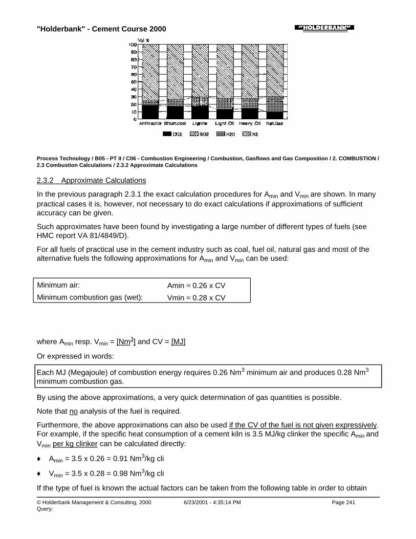
"Holderbank" - Cement Course 2000
© Holderbank Management & Consulting, 2000 6/23/2001 - 4:35:14 PM Page 241Query:
Process Technology / B05 - PT II / C06 - Combustion Engineering / Combustion, Gasflows and Gas Composition / 2. COMBUSTION /2.3 Combustion Calculations / 2.3.2 Approximate Calculations
2.3.2 Approximate Calculations
In the previous paragraph 2.3.1 the exact calculation procedures for Amin and Vmin are shown. In manypractical cases it is, however, not necessary to do exact calculations if approximations of sufficientaccuracy can be given.
Such approximates have been found by investigating a large number of different types of fuels (seeHMC report VA 81/4849/D).
For all fuels of practical use in the cement industry such as coal, fuel oil, natural gas and most of thealternative fuels the following approximations for Amin and Vmin can be used:
Minimum air: Amin ≈ 0.26 x CV
Minimum combustion gas (wet): Vmin ≈ 0.28 x CV
where Amin resp. Vmin = [Nm3] and CV = [MJ]
Or expressed in words:
Each MJ (Megajoule) of combustion energy requires 0.26 Nm3 minimum air and produces 0.28 Nm3
minimum combustion gas.
By using the above approximations, a very quick determination of gas quantities is possible.
Note that no analysis of the fuel is required.
Furthermore, the above approximations can also be used if the CV of the fuel is not given expressively.For example, if the specific heat consumption of a cement kiln is 3.5 MJ/kg clinker the specific Amin andVmin per kg clinker can be calculated directly:
♦ Amin = 3.5 x 0.26 = 0.91 Nm3/kg cli
♦ Vmin = 3.5 x 0.28 = 0.98 Nm3/kg cli
If the type of fuel is known the actual factors can be taken from the following table in order to obtain

"Holderbank" - Cement Course 2000
© Holderbank Management & Consulting, 2000 6/23/2001 - 4:35:14 PM Page 242Query:
somewhat more accurate results.
Type of Fuel Amin-Factor(Nm3/MJ)
Vmin-Factor(Nm3/MJ)
Anthracite, coke at 1% moisture 0.26 0.27
Bituminous coal(low to medium volatile)
at 1...2% moisture 0.26 0.28
Lignite (high volatile) at 10% moisture 0.26 0.29
Wood / Peat at 10...15% moisture 0.26 0.30
Light oil 0.26 0.29
Heavy oil (bunker oil) 0.26 0.28
Tar 0.26 0.28
Waste tires (rubber) 0.26 0.27
Natural gas (high CH4 content) 0.27 0.30
Natural gas (approx. 24% C2H6) 0.26 0.30
Process Technology / B05 - PT II / C06 - Combustion Engineering / Combustion, Gasflows and Gas Composition / 3. GAS FROMRAW MATERIAL
3. GAS FROM RAW MATERIAL
Process Technology / B05 - PT II / C06 - Combustion Engineering / Combustion, Gasflows and Gas Composition / 3. GAS FROMRAW MATERIAL / 3.1 Gases from Dry Raw Meal
3.1 Gases from Dry Raw Meal
If cement raw meal is heated up, hydrate water and CO2 are released.
The true quantity of dry raw meal (not kiln feed) required to produce 1 kg of clinker is called R.Normally R equals to approx. 1.55 kg/kg cli.
R must be calculated from the loss on ignition:
IOLR
..11
−=
[kg/kg cli]
↑loss on ignition of rawmeal in [kg/kg meal]
The above formula applies if the kiln dust is completely returned into the kiln. If some dust is discarded(without return to kiln) the factor R increases accordingly.
The quantity of hydrate water released from dry raw meal is calculated as follows:
"Holderbank" - Cement Course 2000
© Holderbank Management & Consulting, 2000 6/23/2001 - 4:35:14 PM Page 243Query:
H2Ohyd = R x hydrate content x 1.24 [Nm3/kg cli]
↑ (kg hydrate water/kg raw meal)
The quantity of CO2 released from dry raw meal is calculated as follows:
C02 = [R x (1 - hydrate content) - 1] x 0.509 [Nm3/kg cli]
↑ (kg hydrate water /kg raw meal)
Normal dry cement raw meals release approximately the following gas quantities per one kg of clinker:
H2Ohyd ≈ 0.01 Nm3/kg cli
CO2 ≈ 0.27 Nm3/kg cli
Total ≈ 0.28 Nm3/kg cli
In most cases it is sufficient to use the above approximation. If dust is discarded the above value mustbe increased accordingly.
Process Technology / B05 - PT II / C06 - Combustion Engineering / Combustion, Gasflows and Gas Composition / 3. GAS FROMRAW MATERIAL / 3.2 Water from Wet Raw Meal or from Raw Slurry
3.2 Water from Wet Raw Meal or from Raw Slurry
If w (kg/kg) means the moisture or slurry water content of the kiln feed, the amount of water vapor iscalculated as:
24.112 ××
−= R
ww
OH [Nm3/kg cli]
In case of a dry kiln the above quantity is usually negligible, but it is essential on a wet kiln. At a slurrywater content of e.g. 35% it amounts to 1.03 Nm3/kg clinker.
Process Technology / B05 - PT II / C06 - Combustion Engineering / Combustion, Gasflows and Gas Composition / 4. KILN GAS
4. KILN GAS
Process Technology / B05 - PT II / C06 - Combustion Engineering / Combustion, Gasflows and Gas Composition / 4. KILN GAS / 4.1
"Holderbank" - Cement Course 2000
© Holderbank Management & Consulting, 2000 6/23/2001 - 4:35:15 PM Page 244Query:
Measurement of Exhaust Gas Composition
4.1 Measurement of Exhaust Gas Composition
Within this section O2, CO2, CO and N2 are considered. Trace gases such as NOx and SO2 andhydrocarbons belong to the scope of emission measurements and are usually in the order of less than0.1% and are therefore not significant with regard to the main components (O2, CO2, CO, N2).
Process Technology / B05 - PT II / C06 - Combustion Engineering / Combustion, Gasflows and Gas Composition / 4. KILN GAS / 4.1Measurement of Exhaust Gas Composition / 4.1.1 Gas Sampling
4.1.1 Gas Sampling
Although gas sampling may appear as one of the easiest things, it is in fact the source of more than50% of all measuring errors! Sampling can be done either continuously or by extracting a gas sampleinto a rubber bladder.
The aim of sampling is to obtain a representative gas sample from a gas duct into the analyzer. Thepossible problems and solutions in general are as follows:
Problem Solution
Gas is not homogeneouswithin the cross section ofthe gas duct, becausegases do not mix well(sample notrepresentative)
Sample the average of the total cross section (instead ofone sampling point).
Avoid sampling points where poor upstream mixing seemsobvious.
Prefer sampling points after fans (mixing effect of fanblades).
False air is entering intogas sampling system(toomuch O2 in gas sample)
Check tightness of sampling system, especially whensample is extracted from high underpressure.
Avoid small sampling tubing which may become clogged bydust (and produce high suction pressure at low sample gasflow).
In case of spot sampling with rubber bladder: rinse bladderat least once with sample gas.
O2 may react with steeltube at > 400°C (too littleO2 in sample)
Use hot extraction tubes made of sicromal, ceramics orquartz.
CO2 may be absorbed bydust and condensate (toolittle CO2 in sample)
Use a filter directly at the hot extraction point.
Keep sampling system free of dust and condensate(e.g.rubber bladder must be clean inside).
To a certain extent reliable sampling for CO2 will always bea problem as long as gas cooling is applied.

"Holderbank" - Cement Course 2000
© Holderbank Management & Consulting, 2000 6/23/2001 - 4:35:15 PM Page 245Query:
a problem as long as gas cooling is applied.
Long storage time inrubber bladder (too littleCO2 and too much O2 dueto diffusion)
Analyze rubber bladder after 30 min at the latest.
Process Technology / B05 - PT II / C06 - Combustion Engineering / Combustion, Gasflows and Gas Composition / 4. KILN GAS / 4.1Measurement of Exhaust Gas Composition / 4.1.2 The Orsat Apparatus
4.1.2 The Orsat Apparatus
An Orsat apparatus is shown in Fig. 3. A gas sample is filled into a burette volume of 100%. Step bystep, CO2, O2 and CO are absorbed by contacting the gas sample several times with the absorbingagent. The absorbed gas volume is measured after each step in the burette.
Fig. 3 The Orsat Apparatus
It is important to maintain the following, correct sequence of absorption:
1) CO2 → 1) KOH solution
2) O2 1) → 2) pyrogallic acid / KOH
3) CO 1) → 2) Cu2 Cl2 solution
In order to avoid measuring errors the following hints are useful:
1) Check tightness of Orsat apparatus first.
2) Use fresh absorption liquids.
3) While taking a reading always hold liquid level in burette and expansion tank at same height(constant pressure).
4) Check O2 absorption by measuring ambient air (21% O2).
♦ Advantages of the Orsat:
• Measuring principle is very clear and simple
• The Orsat is available (or at least known) in every cement factory

"Holderbank" - Cement Course 2000
© Holderbank Management & Consulting, 2000 6/23/2001 - 4:35:15 PM Page 246Query:
♦ Disadvantages of the Orsat:
• Due to is principle a continuous measurement is impossible
• Analyzing is time consuming
• Although the Orsat can measure CO it is impossible to detect small traces of CO ≤ 0.1%.Therefore the CO result is only useful in cases of „bad“ combustion producing about 0.3 to 1%CO.
Process Technology / B05 - PT II / C06 - Combustion Engineering / Combustion, Gasflows and Gas Composition / 4. KILN GAS / 4.1Measurement of Exhaust Gas Composition / 4.1.3 Other Gas Analyzers
4.1.3 Other Gas Analyzers
In most cases continuous gas analyzers which are permanently installed are used for process controlin a cement kiln (see chapter Exhaust Gas Analysis). Such permanent analyzers measure only at onelocation and are not flexible enough for an investigation of the complete kiln system (involving a largenumber of measuring points).
More and more portable gas analyzers are available on the market. They can usually measure O2, COand combustibles continuously. At fairly low costs (less than $4’000) a quite handy and usefulequipment can be purchased. For an investigation on a cement kiln this is virtually the ideal tool toperform extensive and quick measurements at various locations in the plant.
In the following a few important measuring principles are compared.
Frequent Measuring Principles for O2
♦Paramagnetic effect of O2
• Either thermomagnetical or magneto-mechanical principle is used.
• Thermomagnetical principle is cross-sensitive to gases having other heat conductivities than O2e.g. CO2.
• Magneto-mechanical principle with cell containing movable „dumb-bell“ is not cross-sensitive toCO2 (see Fig. 4A).
• Analyzers based on the paramagnetic effect are the most common type of permanentinstallation in the cement industry.
Fig. 4A Frequent Measuring Principles for Gases -Paramagnetic O2 Sensor
♦ Electrochemical voltage effect of hot zirconium oxide (Fig. 4B)

"Holderbank" - Cement Course 2000
© Holderbank Management & Consulting, 2000 6/23/2001 - 4:35:16 PM Page 247Query:
• Working temperatures above 600°C.
• Measuring the voltage of an electrochemical cell, according to the equation:
×=
fPOPO
nFRT
ERe
ln2
2[V]
(R = Gas constant, T = [K], n = 4, F = Faraday constant, PO2 = partial pressure of oxygen)
• Logarithmic output signal, depending on PO2.
• Principle is seldom used.
Fig. 4B Frequent Measuring Principles of Gases -Zirconiumoxide Cell
♦ „Self consuming“ electromechanical sensors (Fig. 4C)
• Basic design of such a measuring cell is similar to a normal battery. Cell consists of anode,electrolyte and air cathode (see Fig. 4C).
• O2 enters via diffusion barrier to cathode.
• At the air-cathode O2 is reduced to OH. Thereby an electrical current is produced which isproportional to the O2 content and is used as output signal.
• Above reaction causes an irreversible consumption of the anode (lead). Therefore lifetime ofthe cell is limited.
• Practical lifetime of such a cell is about 1 year (even if cell is not in use a certain aging occurs).
• Reliable measurements without major cross-sensitivities.
• Calibration only with air (zero is self adjusting).
• Application: Portable low cost analyzers.
• Similar applications: Other electrochemical sensors have been developed for CO, SO2 and NOxworking on similar principles. By special design and compensation the effect of„self-consumption“ could be avoided. These analyzers are widely used for portable applicationsbut not for permanent emission control.
Fig. 4C Frequent Measuring Principles for Gases -

"Holderbank" - Cement Course 2000
© Holderbank Management & Consulting, 2000 6/23/2001 - 4:35:16 PM Page 248Query:
Electrochemical Cell
Process Technology / B05 - PT II / C06 - Combustion Engineering / Combustion, Gasflows and Gas Composition / 4. KILN GAS / 4.1Measurement of Exhaust Gas Composition / 4.1.4 Reference to Dry or Wet
4.1.4 Reference to Dry or Wet
The most frequent type of gas sampling includes a cooling of the gas to approx. 0°C (or at least toroom temperature). By this cooling the water vapor is condensed and the measurement in the gasanalyzer refers to dry gas.
The reference to dry gas will be considered as „normal case“ in this paper (unless otherwise noted).
The „classic analyzer“ - the Orsat apparatus - refers always to dry gas. For this particular analyzereven some residual water content in the gas sample will not affect the final result, the reading meansexactly the dry composition (in this case it would even be wrong to make any correction for residualwater vapor in the gas sample!).
Note that there are exceptional cases e.g. where gas samples are not condensed but introduceddirectly in a hot zirconium oxide cell. In such a case the result will refer to wet gas. Furthermoresampling systems without gas coolers but with dilution of the hot gas instead (thus avoiding any watercondensation) exist, but they are hardly used for O2, CO, CO2.
Summarizing, sampling with gas cooling and reference to dry gas is considered as normal, i.e. is usedfor about 99% of all practical measurements.
Process Technology / B05 - PT II / C06 - Combustion Engineering / Combustion, Gasflows and Gas Composition / 4. KILN GAS / 4.1Measurement of Exhaust Gas Composition / 4.1.5 Determination of Water Content
4.1.5 Determination of Water Content
Since all measuring systems described above are not able to measure water, other methods have tobe used if water really has to be measured. Important methods are:
♦ Two temperatures method:
• Measuring of wet bulb and dry bulb temperature.
• If the gas temperature is < 150°C wet and dry bulb temperature can be measured directly in thegas duct. If the gas temperature is > 150°C an extraction of the gas and cooling down to <150°C is required.
• Evaluation of gas moisture according to calculation sheet 32599e (see measuring techniquespart of cement course).
• Method is preferred due to its simplicity, however accuracy at high moisture contents may not

"Holderbank" - Cement Course 2000
© Holderbank Management & Consulting, 2000 6/23/2001 - 4:35:16 PM Page 249Query:
be always sufficient.
♦ Condensation method:
• A gas sample is extracted for a certain time and cooled by ice water, thus water is condensed.
• The remaining dry gas extracted is measured by a volume counter.
• By measuring the weight of the condensate the moisture content of the gas can be calculated.
Process Technology / B05 - PT II / C06 - Combustion Engineering / Combustion, Gasflows and Gas Composition / 4. KILN GAS / 4.2Immediate Calculations from Gas Composition
4.2 Immediate Calculations from Gas Composition
Process Technology / B05 - PT II / C06 - Combustion Engineering / Combustion, Gasflows and Gas Composition / 4. KILN GAS / 4.2Immediate Calculations from Gas Composition / 4.2.1 Dew Point
4.2.1 Dew Point
From the water content the dew point can be calculated.
♦ Vf [Nm3/Nm3w] is the volume fraction of water vapor in the wet gas
♦ Ptot [bar] is the total pressure (usually assumed as 1.0133 bar)
By expressing the vapor pressure in form of a numerical equation the following dew point formula wasdeveloped for precise calculations:
( )179
ln045.173362.548.336
−×+−
=totPVf
τ[C]
Example:
Vf = 0.10 Nm3/Nm3w Ptot = 1.0133 bar
( )C
PVfo
tot
09.46
179ln045.173362.5
48.336
=
−×+−
=
τ
τ
The corresponding inverse function giving the saturation pressure of water (PW) is as follows:
( )
++
+−= 2179
113216179
35914297.11
ttEXPPW [bar]
t = 0...120°C, max. deviation ± 0.03%.
A section of the above function is shown in Fig. 5 which can be used for graphical evaluation of the
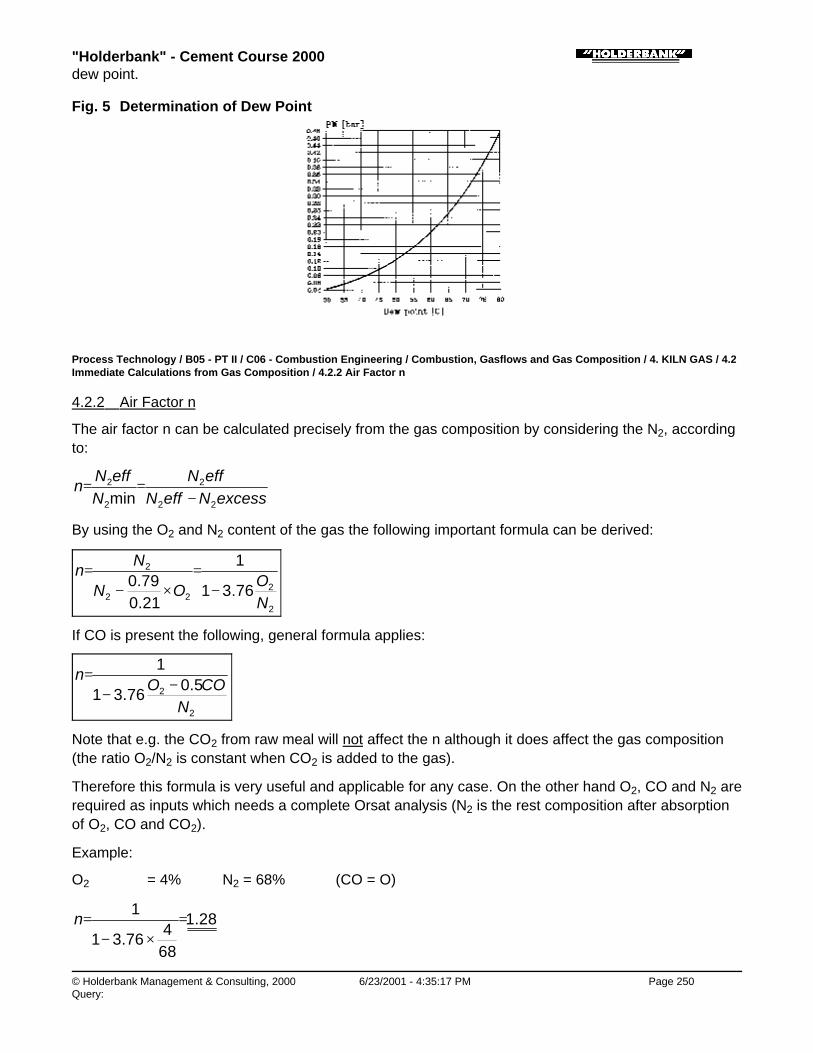
"Holderbank" - Cement Course 2000
© Holderbank Management & Consulting, 2000 6/23/2001 - 4:35:17 PM Page 250Query:
dew point.
Fig. 5 Determination of Dew Point
Process Technology / B05 - PT II / C06 - Combustion Engineering / Combustion, Gasflows and Gas Composition / 4. KILN GAS / 4.2Immediate Calculations from Gas Composition / 4.2.2 Air Factor n
4.2.2 Air Factor n
The air factor n can be calculated precisely from the gas composition by considering the N2, accordingto:
excessNeffNeffN
NeffN
n22
2
2
2
min −==
By using the O2 and N2 content of the gas the following important formula can be derived:
2
222
2
76.31
1
21.079.0
NO
ON
Nn
−=
×−=
If CO is present the following, general formula applies:
2
2 5.076.31
1
NCOO
n−−
=
Note that e.g. the CO2 from raw meal will not affect the n although it does affect the gas composition(the ratio O2/N2 is constant when CO2 is added to the gas).
Therefore this formula is very useful and applicable for any case. On the other hand O2, CO and N2 arerequired as inputs which needs a complete Orsat analysis (N2 is the rest composition after absorptionof O2, CO and CO2).
Example:
O2 = 4% N2 = 68% (CO = O)
28.1
684
76.31
1=
×−=n

"Holderbank" - Cement Course 2000
© Holderbank Management & Consulting, 2000 6/23/2001 - 4:35:17 PM Page 251Query:
Process Technology / B05 - PT II / C06 - Combustion Engineering / Combustion, Gasflows and Gas Composition / 4. KILN GAS / 4.2Immediate Calculations from Gas Composition / 4.2.3 Combustion Efficiency
4.2.3 Combustion Efficiency
Unburned gases are a sign of incomplete combustion. The most important unburned gas is CO,whereas hydrocarbons are usually < 0.1% on a cement kiln and can be neglected with regard toenergy losses.
If only CO is known the loss due to incomplete combustion is:
Q = (dry gas quantity) x CO x 12.6 [MJ]
↑[Nm3] ↑[Nm3/Nm3]
Example:
On a cement kiln the fuel combustion is 3.3 MJ/kg clinker, the dry exhaust gas quantity is 1.3 Nm3/kgclinker and the CO content = 0.2%.
q = 1.3 x 0.002 x 12.6 = 0.033 MJ/kg cli
Relative loss = %101.0
3.3033.0
==MJ
MJ
Some gas analyzers have also a combustible sensor based on a catalytic combustion of the samplegas. Such a sensor responses to all types of combustible gases (CO, H2, CH4, C2H6 etc.). Although themain combustible component is not CH4 (methane) but rather CO it is common to express the result as„CH4 equivalent“.
If the total of combustibles is given as their „CH4 equivalent“ the loss is:
Q = (dry gas quantity) x CH4 x 35.8 [MJ]
↑[Nm3] ↑[Nm3/Nm3]
Process Technology / B05 - PT II / C06 - Combustion Engineering / Combustion, Gasflows and Gas Composition / 4. KILN GAS / 4.2Immediate Calculations from Gas Composition / 4.2.4 Gas Density
4.2.4 Gas Density
The gas density at normal conditions can be calculated by a simple mix calculation by using thefollowing densities:
Gas M[kg/kmol]
Density*[kg/Nm3]
O2 32.0 1.429
CO2 44.0 1.964
"Holderbank" - Cement Course 2000
© Holderbank Management & Consulting, 2000 6/23/2001 - 4:35:18 PM Page 252Query:
CO2
CO 28.0 1.250
„N2“** 28.15 1.257
H2O 18.0 0.804
* Density in a gas mixture (considered) as ideal gas
** Not as pure N2 but as „rest“ in the air (including also Ar and trace gases)
Note: For the calculation of the true gas density all concentrations (O2, CO2, CO, N2,H2O) are to be referred to wet gas here.
Example:
Exhaust gas density of a suspension preheater kiln with coal firing:
Gascomponent
Compositionof dry gas[Vol%]
Compositionof wet gas[Vol%]
O2
CO2
CON2
4%31%0%65%
0.9 x 4 = 3.6%0.9 x 31 = 27.9%
0.9 x 65 = 58.5%
100 - 10 = 90%
H2O -- 10 %
Total 100% 100 %
Density = 0.036 x 1.429 + 0.279 x 1.964
+ 0.585 x 1.257 + 0.10 x 0.804 = 1.415 kg/Nm3
(at normal conditions)
Process Technology / B05 - PT II / C06 - Combustion Engineering / Combustion, Gasflows and Gas Composition / 4. KILN GAS / 4.3Calculation of Exhaust Gas Quantities
4.3 Calculation of Exhaust Gas Quantities
Process Technology / B05 - PT II / C06 - Combustion Engineering / Combustion, Gasflows and Gas Composition / 4. KILN GAS / 4.3Calculation of Exhaust Gas Quantities / 4.3.1 Firing / Hot Gas Generator
4.3.1 Firing / Hot Gas Generator
The following calculation applies for any type of firing where gases are coming only from fuelcombustion and excess air (no gases from raw meal).
Problem: The fuel consumption Q = [MJ/h] of the firing is known and the complete exhaust gas

"Holderbank" - Cement Course 2000
© Holderbank Management & Consulting, 2000 6/23/2001 - 4:35:18 PM Page 253Query:
analysis (CO2, O2, CO, N2) is given. By means of this information the gas flow [Nm3/h] shall becalculated.
Solution: Calculate first the n according to 4.2.2:
2
2 5.076.31
1
NCOO
n−−
=
The gas flow V [Nm3/h] is then:
V = Q [Vmin + (n - 1) Amin] [Nm3/h]
Vmin and Amin are in [Nm3/MJ] and can either be calculated exactly according to 2.3.1 or just simply byintroducing the approximations according to 2.3.2, namely:
♦ Vmin ≈ 0.28 Nm3/MJ
♦ Amin ≈ 0.26 Nm3/MJ
If the complete gas analysis is not known but only the O2 concentration (dry) a further approximationfor the dry amount of Vmin, namely 0.25 Nm3/MJ, has to be introduced which results in the followingapproximation formula:
−
+×=2
2
%21%
25.028.0O
OQV
[Nm3/h]
↑ [MJ/h] O2 ref. to dry
Note: If the O2 was based on wet gas the above formula would become even more simple, namely:
2%2121
28.0O
QV−
××≈
Process Technology / B05 - PT II / C06 - Combustion Engineering / Combustion, Gasflows and Gas Composition / 4. KILN GAS / 4.3Calculation of Exhaust Gas Quantities / 4.3.2 Cement Kiln
4.3.2 Cement Kiln
On a cement kiln it is common practice to work with specific quantities referred to 1 kg of clinker,therefore the fuel consumption is expressed in q [MJ/kg cli] and V means here [Nm3/kg cli].
The general calculation formula is:
V = q (Vmin + (n -1) x Amin) + (gas from RM) [Nm3/kg cli]
↑ [MJ/kg cli] ↑ [Nm3/kg cli]

"Holderbank" - Cement Course 2000
© Holderbank Management & Consulting, 2000 6/23/2001 - 4:35:19 PM Page 254Query:
n is calculated from the complete gas composition according to 4.2.2.
If only O2 concentrations are available the following approximations can be used for dry kilns:
- from combustion 0.28 * q [Nm3/kg cli]
- from raw meal 0.28 [Nm3/kg cli]
- excess air plus false air ( )2
2
%21%
25.028.0O
Oq
−××+ [Nm3/kg cli]
Total = V = 0.28 (q+1) + (0.28+0.25xq) x 2
2
%21%
OO
−[Nm3/kg cli]
↑
[MJ/kg cli]
In case of wet raw meal or for wet kilns additional water has to be added (see 3.2) to the above result.
The above approximation can be used in form of diagram (Fig. 6)
Fig. 6 Quick Determination of Kiln Exhaust Gas Quantity
Example:
Dry kiln, q = 3.3 MJ/kg cli, O2 = 3.5%
Total gas = 0.28 (3.3+1) + (0.28+0.25x3.3) x 5.3215.3
− = 1.425 Nm3/kg cli
Three typical results for cement kilns are shown in Fig. 7.

"Holderbank" - Cement Course 2000
© Holderbank Management & Consulting, 2000 6/23/2001 - 4:35:19 PM Page 255Query:
Fig. 7 Typical Exhaust Gas Quantities for Three Cement Kiln Systems
Process Technology / B05 - PT II / C06 - Combustion Engineering / Combustion, Gasflows and Gas Composition / 4. KILN GAS / 4.4Calculation of the CO2 Content of Cement Kiln Exhaust Gas
4.4 Calculation of the CO2 Content of Cement Kiln Exhaust Gas
Process Technology / B05 - PT II / C06 - Combustion Engineering / Combustion, Gasflows and Gas Composition / 4. KILN GAS / 4.4Calculation of the CO2 Content of Cement Kiln Exhaust Gas / 4.4.1 Introduction
4.4.1 Introduction
If no measured CO2 concentration is available it is possible to complete the gas analysis with acalculated CO2 concentration. This can be useful e.g. for calculation of density or specific heat.
It is possible to calculate the CO2 content at any point in the exhaust gas system (suspensionpreheater, cooling tower, raw mill, filter) of a cement kiln if the corresponding O2 concentration isknown.
The calculation is based on two main facts:
1) The CO2 balance applies (CO2 comes from combustion and from raw meal)
2) Starting from the O2 concentration the corresponding dilution with air can be quantified.
In addition a few other preconditions are to be observed here:
♦ Reference is made to dry gas composition.
♦ The assumption is made that all CO2 from raw meal is in the kiln gas (i.e. after completecalcination).
♦ No gas is lost or extracted from the gas stream under consideration (e.g.: an upstream extractionof a bypass gas is excluded here).
♦ For numerical calculations the following approximations are used:
• CO2 from raw meal ≈ 0.27 Nm3/kg cli
• N2 from combustion at n = 1N2 = 0.79 x Amin + N2 from fuel = 0.79 x 0.26 + 0.0015 ≈ 0.207 Nm3/MJ (this approximation is very accurate for all types of fuels)

"Holderbank" - Cement Course 2000
© Holderbank Management & Consulting, 2000 6/23/2001 - 4:35:19 PM Page 256Query:
Process Technology / B05 - PT II / C06 - Combustion Engineering / Combustion, Gasflows and Gas Composition / 4. KILN GAS / 4.4Calculation of the CO2 Content of Cement Kiln Exhaust Gas / 4.4.2 Maximum CO2 Content
4.4.2 Maximum CO2 Content
In a first step the influence of dilution (or excess air) is assumed as zero (0% O2). Therefore atheoretical, maximum CO2 content can be calculated from the CO2 balance.
The dry gas contains only CO2 and N2 which can be calculated as follows:
CO2 = 0.27 + cf x q [Nm3/kg cli]
N2 = 0.207 x q [Nm3/kg cli]
q [MJ/kg cli] = specific heat consumption
cf [Nm3/MJ] = CO2 from fuel, referred to CV
cf depends on the type of fuel and can be calculated according to paragraph 2.3.1.2 (by consideringonly the CO2 term in the Vmin formula).
Typical values for cf are:
Coal = 0.050 Nm3 CO2/MJ
Fuel oil = 0.039 Nm3 CO2/MJ
Natural gas = 0.028 Nm3 CO2/MJ
The concentration CO2max is calculated from the above quantities of CO2 and N2:
22
2max2 NCO
COCO
+= [Nm3/Nm3]
Process Technology / B05 - PT II / C06 - Combustion Engineering / Combustion, Gasflows and Gas Composition / 4. KILN GAS / 4.4Calculation of the CO2 Content of Cement Kiln Exhaust Gas / 4.4.3 True CO2 Content
4.4.3 True CO2 Content
Due to dilution of the gas with air and due to possible formation of some CO the true CO2 content is:
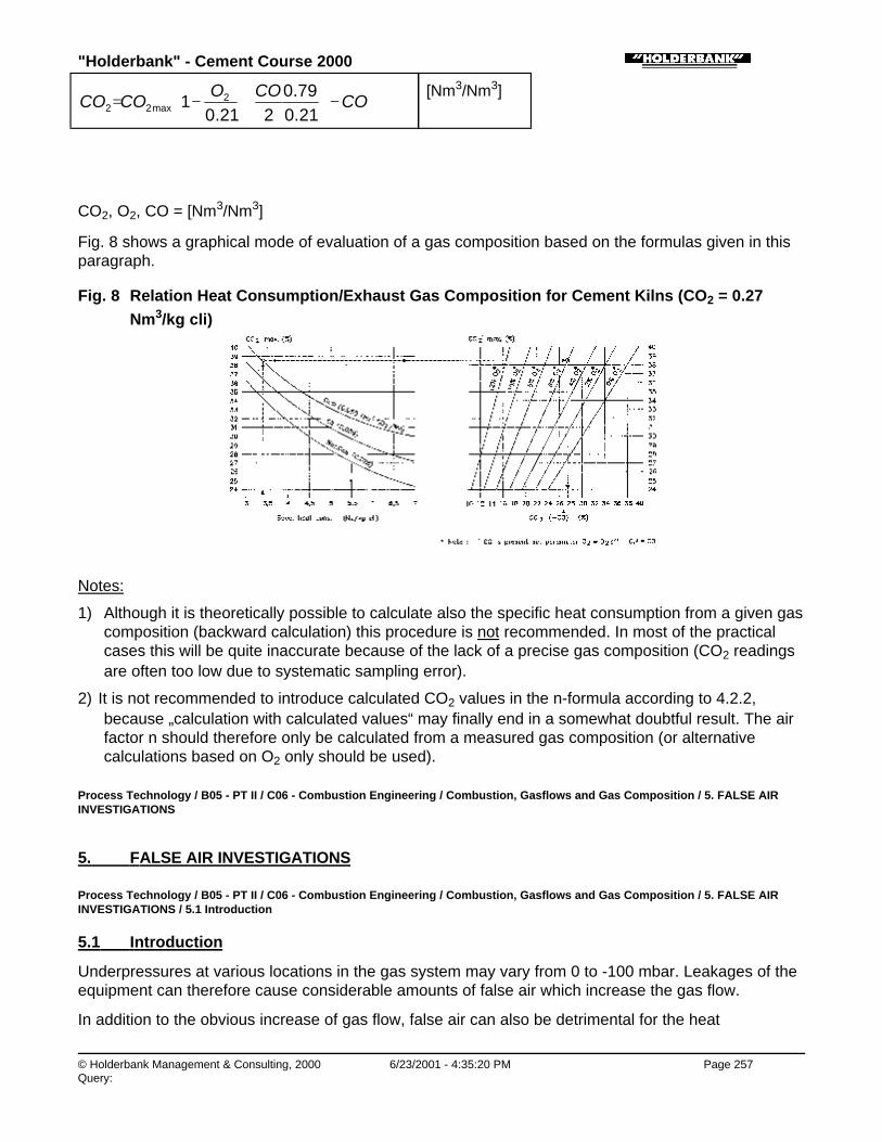
"Holderbank" - Cement Course 2000
© Holderbank Management & Consulting, 2000 6/23/2001 - 4:35:20 PM Page 257Query:
COCOO
COCO −
+−=
21.079.0
221.01 2
max22
[Nm3/Nm3]
CO2, O2, CO = [Nm3/Nm3]
Fig. 8 shows a graphical mode of evaluation of a gas composition based on the formulas given in thisparagraph.
Fig. 8 Relation Heat Consumption/Exhaust Gas Composition for Cement Kilns (CO2 = 0.27Nm3/kg cli)
Notes:
1) Although it is theoretically possible to calculate also the specific heat consumption from a given gascomposition (backward calculation) this procedure is not recommended. In most of the practicalcases this will be quite inaccurate because of the lack of a precise gas composition (CO2 readingsare often too low due to systematic sampling error).
2) It is not recommended to introduce calculated CO2 values in the n-formula according to 4.2.2,because „calculation with calculated values“ may finally end in a somewhat doubtful result. The airfactor n should therefore only be calculated from a measured gas composition (or alternativecalculations based on O2 only should be used).
Process Technology / B05 - PT II / C06 - Combustion Engineering / Combustion, Gasflows and Gas Composition / 5. FALSE AIRINVESTIGATIONS
5. FALSE AIR INVESTIGATIONS
Process Technology / B05 - PT II / C06 - Combustion Engineering / Combustion, Gasflows and Gas Composition / 5. FALSE AIRINVESTIGATIONS / 5.1 Introduction
5.1 Introduction
Underpressures at various locations in the gas system may vary from 0 to -100 mbar. Leakages of theequipment can therefore cause considerable amounts of false air which increase the gas flow.
In addition to the obvious increase of gas flow, false air can also be detrimental for the heat
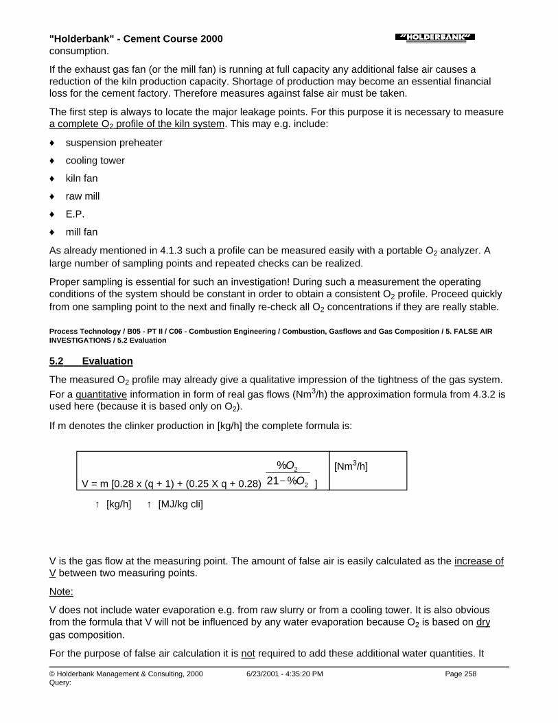
"Holderbank" - Cement Course 2000
© Holderbank Management & Consulting, 2000 6/23/2001 - 4:35:20 PM Page 258Query:
consumption.
If the exhaust gas fan (or the mill fan) is running at full capacity any additional false air causes areduction of the kiln production capacity. Shortage of production may become an essential financialloss for the cement factory. Therefore measures against false air must be taken.
The first step is always to locate the major leakage points. For this purpose it is necessary to measurea complete O2 profile of the kiln system. This may e.g. include:
♦ suspension preheater
♦ cooling tower
♦ kiln fan
♦ raw mill
♦ E.P.
♦ mill fan
As already mentioned in 4.1.3 such a profile can be measured easily with a portable O2 analyzer. Alarge number of sampling points and repeated checks can be realized.
Proper sampling is essential for such an investigation! During such a measurement the operatingconditions of the system should be constant in order to obtain a consistent O2 profile. Proceed quicklyfrom one sampling point to the next and finally re-check all O2 concentrations if they are really stable.
Process Technology / B05 - PT II / C06 - Combustion Engineering / Combustion, Gasflows and Gas Composition / 5. FALSE AIRINVESTIGATIONS / 5.2 Evaluation
5.2 Evaluation
The measured O2 profile may already give a qualitative impression of the tightness of the gas system.For a quantitative information in form of real gas flows (Nm3/h) the approximation formula from 4.3.2 isused here (because it is based only on O2).
If m denotes the clinker production in [kg/h] the complete formula is:
V = m [0.28 x (q + 1) + (0.25 X q + 0.28) 2
2
%21%
OO
− ]
[Nm3/h]
↑ [kg/h] ↑ [MJ/kg cli]
V is the gas flow at the measuring point. The amount of false air is easily calculated as the increase ofV between two measuring points.
Note:
V does not include water evaporation e.g. from raw slurry or from a cooling tower. It is also obviousfrom the formula that V will not be influenced by any water evaporation because O2 is based on drygas composition.
For the purpose of false air calculation it is not required to add these additional water quantities. It

"Holderbank" - Cement Course 2000
© Holderbank Management & Consulting, 2000 6/23/2001 - 4:35:20 PM Page 259Query:
would be even wrong to add such quantities to V before calculating the false air as difference betweentwo V-valves.
Process Technology / B05 - PT II / C06 - Combustion Engineering / Combustion, Gasflows and Gas Composition / 5. FALSE AIRINVESTIGATIONS / 5.3 Example of an Investigation
5.3 Example of an Investigation
On a dry suspension preheater kiln with cooling tower and roller mill in combined operation the O2profile was checked by means of 5 sampling points.
The clinker production is 100 t/h with a specific consumption of 3400 kJ/kg cli.
Fig. 9 shows the evaluation of the results by calculating the V [Nm3/h] for every sampling point.
Fig. 9 False Air Investigation on a Kiln System
V equals to the true wet exhaust gas quantity at the sampling points 1 and 2. For the points 3, 4 and 5the amount of water vapor from cooling tower and the amount of water evaporated in the raw mill is notincluded in V.
The false air flows are simply calculated as the increase of V.
The final result gives the amounts of false air inleak (Nm3/h) for each section. These values areneeded in order to evaluate the possible potential for optimization.
Conclusion:
For the example according to Fig. 9 the exhaust gas quantity after preheater is 145’800 Nm3/h which isfinally mixed with up to 101’700 Nm3/h or 70% of false air when it reaches the chimney. Therefore clearoptimization potentials exist in the area of the cooling tower, the raw mill and the electrofilter.

"Holderbank" - Cement Course 2000
© Holderbank Management & Consulting, 2000 6/23/2001 - 4:35:21 PM Page 260Query:
Process Technology / B05 - PT II / C07 - Alternative Fuels
C07 - Alternative Fuels

"Holderbank" - Cement Course 2000
© Holderbank Management & Consulting, 2000 6/23/2001 - 4:35:21 PM Page 261Query:
Process Technology / B05 - PT II / C07 - Alternative Fuels / Use of Alternative Fuels
Use of Alternative FuelsA. ObristPT 96/14024/E (Modification 2000)
1. INTRODUCTION
2. TYPES OF ALTERNATIVE FUELS
3. UTILIZATION IN CEMENT KILNS
3.1 List of Applications
3.2 Feedpoints for Alternative Fuels
3.3 Substitution effect and potential capacity loss
3.4 Supply and Inlet Control
4. EMISSIONS IN CONTEXT WITH ALTERNATIVE FUELS
4.1 Introduction
4.2 General Features of Cement Kiln Systems
4.3 Special rules regarding emission behaviour on cement kilns
5. ADVANTAGES / DISADVANTAGES
6. PRACTICAL APPLICATIONS
6.1 Waste Tires
6.2 Domestic Refuse / RDF
6.3 Burning of Contaminated Waste Oil
6.4 Burning pure waste oil
6.5 Burning of Waste Wood at Rekingen
6.6 Mixed examples
SUMMARY
The use of alternative fuels (AF) in cement kilns can save costs and contribute to the solution ofenvironmental problems. The paper on hand concentrates on technical and environmental aspects.
Rules on how to use alternative fuels and possible impacts are given. Practical examples are attached(flowsheets).
Process Technology / B05 - PT II / C07 - Alternative Fuels / Use of Alternative Fuels / 1. INTRODUCTION
1. INTRODUCTION
♦ Burning of alternative fuels (AF) in cement kilns offers unique advantages from an environmental

"Holderbank" - Cement Course 2000
© Holderbank Management & Consulting, 2000 6/23/2001 - 4:35:21 PM Page 262Query:
point of view (high temperatures, long retention, no solid residues, no increase of emission, overallreduction of CO2 emission).
♦ Using alternative fuels saves costs. Two main factors contribute to this1) Thermal substitution rate (there are technical limits)2) Low or even negative energy price (USD per GJ) for AF’s
♦ Logically only fuels that are significantly cheaper than conventional fuels (USD per GJ) can createcost savings. However, even if AF’s are cheaper all the additional costs involved have to beconsidered to make it profitable (preparation, additional production costs, maintenance, reductionof OEE, etc.)
♦ Within the Holderbank, Group 52 plants are using significant amounts of AF. The average thermalsubstitution rate of all 105 plants is 12.3% (1998).The fuel cost substitution rate (which is not the same as thermal substitution rate) is not yet beingreported and the difficulty is to get an objective and fair consideration of all additional costsinvolved. From the basic principle cost substitution rates of over 100% are possible at negative fuelprices, but so far very exceptional.
Process Technology / B05 - PT II / C07 - Alternative Fuels / Use of Alternative Fuels / 2. TYPES OF ALTERNATIVE FUELS
2. TYPES OF ALTERNATIVE FUELS
By definition, fuels, which are not traded in the normal fuel market, are considered as "alternativefuels". Petcoke e.g. is not classified as “alternative fuel” and is listed in a separate application list (nottreated here).
Alternative fuels can be roughly divided into solid and liquid fuels (gaseous is negligible).
Whether it is simple or difficult to use an alternative fuel depends much on its physical properties. E.g.it may be very simple to use waste oil which has been purified by the supplier. On the other hand it isimpossible to use e.g. raw domestic refuse directly as solid fuel, because it is of poor quality and veryinhomogeneous. The only practical way to burn it in a cement kiln is a sophisticated pre-treatment toproduce RDF (refuse derived fuel).
Table (1) shows a list of alternative fuels in the order of their CV compared to conventional fuels. Thecalorific value alone does not directly indicate the potential to save costs. E.g. waste tires are as goodas coal from the viewpoint of CV but require expensive handling and tend to cause negative impacts onthe kiln process, so an adequate compensation must be included in the price (disposal fee).
Table 1 Various Alternative and Conventional Fuels,grouped according to their CV
(*= conventional fuel)
Material CV [MJ/kg]net
Pure polyethylene 3) 46
* Light oil 42
* Heavy oil 40
Tar (by-product) 38

"Holderbank" - Cement Course 2000
© Holderbank Management & Consulting, 2000 6/23/2001 - 4:35:21 PM Page 263Query:
Tar (by-product) 38
Pure rubber (without inert material) 36
* Anthracite 34
Aluminium metal 1) 31
Waste oils, various refinery wastes 30 to 40
* Petcoke 33
Waste tires 28 to 32
* Bituminous coal (low ash) 29
* Bituminous coal (high ash) 24
Liquid mix (CSS from SCORIBEL or SYNFUEL from SafetyKleen)
20 to 30
Landfill gas 16 to 20 (MJ/Nm3)
Acid sludge, acid tar (from oil reprocessing) 16 to 22
* Lignite (10% moisture) 16 to 21
Pot liners (from aluminium smelter) 20
PVC 3) 19
Palm nut shells (10% moisture) 19
Pressed olive cake 18
Dried wood, bark, saw dust (10% moisture) 16
Rice husks (10% moisture) 16
Car shredder wastes 15
RDF (from domestic refuse, 10% moisture) 15
Animal meal 15
Cardboard, paper (air dry) 15
Impregnated saw dust (25% moisture) 10 to 12
Dried sewage sludge (10% moisture) 10
Fuller’s earth (from oil purification, LD actual) 10
Domestic refuse (30% moisture) 8.5
Dried sewage sludge (30% moisture) 7.5
Pure iron 2) 7.5
1) Al metal may occur e.g. in composite packaging wastes and is oxidised to Al2O3
2) Fe metal occurs e.g. in waste tires and is oxidised to Fe2O3
3) Usually not in pure form, but contained in mixed plastics
Process Technology / B05 - PT II / C07 - Alternative Fuels / Use of Alternative Fuels / 3. UTILIZATION IN CEMENT KILNS
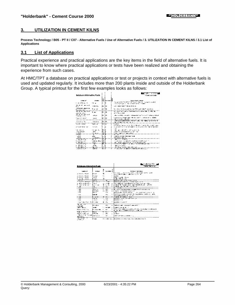
"Holderbank" - Cement Course 2000
© Holderbank Management & Consulting, 2000 6/23/2001 - 4:35:22 PM Page 264Query:
3. UTILIZATION IN CEMENT KILNS
Process Technology / B05 - PT II / C07 - Alternative Fuels / Use of Alternative Fuels / 3. UTILIZATION IN CEMENT KILNS / 3.1 List ofApplications
3.1 List of Applications
Practical experience and practical applications are the key items in the field of alternative fuels. It isimportant to know where practical applications or tests have been realized and obtaining theexperience from such cases.
At HMC/TPT a database on practical applications or test or projects in context with alternative fuels isused and updated regularly. It includes more than 200 plants inside and outside of the HolderbankGroup. A typical printout for the first few examples looks as follows:
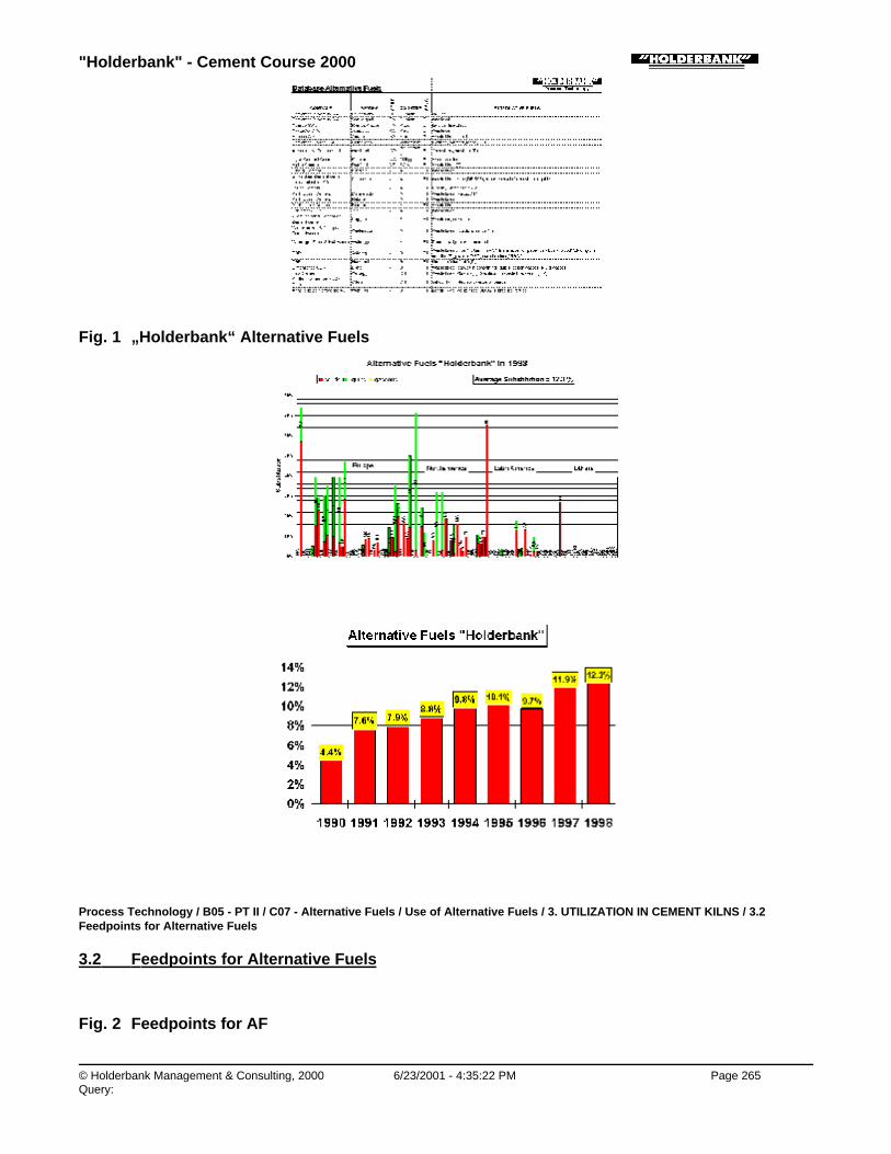
"Holderbank" - Cement Course 2000
© Holderbank Management & Consulting, 2000 6/23/2001 - 4:35:22 PM Page 265Query:
Fig. 1 „Holderbank“ Alternative Fuels
Process Technology / B05 - PT II / C07 - Alternative Fuels / Use of Alternative Fuels / 3. UTILIZATION IN CEMENT KILNS / 3.2Feedpoints for Alternative Fuels
3.2 Feedpoints for Alternative Fuels
Fig. 2 Feedpoints for AF
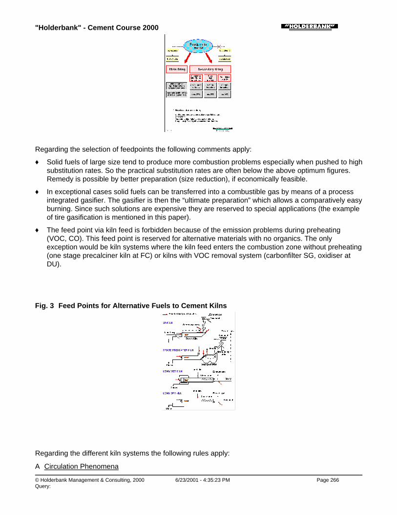
"Holderbank" - Cement Course 2000
© Holderbank Management & Consulting, 2000 6/23/2001 - 4:35:23 PM Page 266Query:
Regarding the selection of feedpoints the following comments apply:
♦ Solid fuels of large size tend to produce more combustion problems especially when pushed to highsubstitution rates. So the practical substitution rates are often below the above optimum figures.Remedy is possible by better preparation (size reduction), if economically feasible.
♦ In exceptional cases solid fuels can be transferred into a combustible gas by means of a processintegrated gasifier. The gasifier is then the “ultimate preparation” which allows a comparatively easyburning. Since such solutions are expensive they are reserved to special applications (the exampleof tire gasification is mentioned in this paper).
♦ The feed point via kiln feed is forbidden because of the emission problems during preheating(VOC, CO). This feed point is reserved for alternative materials with no organics. The onlyexception would be kiln systems where the kiln feed enters the combustion zone without preheating(one stage precalciner kiln at FC) or kilns with VOC removal system (carbonfilter SG, oxidiser atDU).
Fig. 3 Feed Points for Alternative Fuels to Cement Kilns
Regarding the different kiln systems the following rules apply:
A Circulation Phenomena

"Holderbank" - Cement Course 2000
© Holderbank Management & Consulting, 2000 6/23/2001 - 4:35:24 PM Page 267Query:
♦ Kiln systems with cyclon suspension preheater and without bypass are most sensitive tocirculating phenomena. If the following criteria are not respected, the AF use will cause severeproblems or will fail- Keep total chlorine input below 200 – 300 mg/kg clinker (from all fuels and raw materials). Ifthis limit is exceeded a bypass is required. The cyclone preheater without bypass is notforgiving excessive Cl input, it will just plug.- Keep sulfur cycles under control! Unlike Cl the most critical factor is not the possible sulfurinput by AF but the impact of poor AF combustion on sulfur volatilisation. This will promote ahigh sulfur cycle and sulfur pluggings. Remedies: improve combustion, higher O2 at kiln inlet,enhanced preheater cleaning.
♦ Kiln systems with grate preheater (Lepol) are of similar sensitivity to circulating phenomena ascyclone preheater kilns. Condensation of volatile elements in the nodule bed on the preheater candisturb its permeability and thus the kiln operation.
♦ Long dry kilns or long wet kilns are more forgiving in terms of circulating phenomena as theyhave no critical narrow cross sections. However, rings and build-ups in the rotary kiln also occur butit takes longer until they grow to a critical size. If the kiln system works with 100% dustreintroduction the sustainable chlorine limit is the same as on a cyclone preheater kiln (200 – 300mg/kg clinker).The difference to the cyclone preheater kiln is that it is easy to realize a valve for chlorine on a wetkiln if the kiln is equipped with an EP dedusting. This allows to extract a highly enriched fine dustselectively that removes chlorine effectively when being discarded. Like that up to 5000 mg/kg clichlorine input can be handled. In this case the discarded dust causes an additional disposalproblem, because it cannot be added to the cement due to the chlorine limit for cement (0.1% Cl).
♦
Chlorine limit
Regarding the chlorine input the following diagram helps to get a quick overview of what can beaccepted as total input if then chlorine would come only from AFR (whether it’s a Fuel or a Rawmaterial does not matter here).
The following limits apply:
Limit A: Normal SP kiln with completely closed dust loop
Limit B: SP kiln with some 20% bypass or wet kiln discarding medium dust quantities
Limit C: Maximum possible for wet kiln discarding high dust or SP kiln with 100% bypass
Example:
An AFR with 1% Cl at a relative input of 10 g AFR per kg clinker creates an input of 100 mg Cl/kg cli,which is not critical (assuming no other inputs of Cl).
Fig. 4 Chlorine Input by AFR

"Holderbank" - Cement Course 2000
© Holderbank Management & Consulting, 2000 6/23/2001 - 4:35:24 PM Page 268Query:
B Temperature and gas residence line
If stable toxic organic compounds in AF’s are an issue the main kiln features for their destruction haveto be known.
♦ Main firing- Flame temperature 1800 – 2000°C- Total gas residence time in rotary kiln depends on kiln system as follows - short kiln (2 support) approx. 3 sec. - normal SP/PC kiln more than 5 sec. - long wet or dry kiln more than 10 sec.
So typically a gas residence time of approx. 5 sec. above 1200°C can be expected.
♦ Secondary firing (no PC), with unextended riser duct 1 sec. above 820°C
♦ Precalciner with tertiary air 2-4 sec. above 860°C (in case of hot spot design peaks up to 1200°C)
For optimum combustion and safe destruction of stable organics only the main firing shall be used.Example: waste oil that is contaminated with traces of PCB.
Other feedpoints are reserved for less critical AF’s or if they are used for critical substances tests maybecome necessary. To avoid extensive tests it is often easier to select the main firing.
Finally the above temperatures are not valid for start up or upset conditions so critical AF’s should onlybe used under normal operating conditions.
Process Technology / B05 - PT II / C07 - Alternative Fuels / Use of Alternative Fuels / 3. UTILIZATION IN CEMENT KILNS / 3.3Substitution effect and potential capacity loss
3.3 Substitution effect and potential capacity loss
Introduction
If low grade fuels are used to substitute high grade conventional fuels (coal, oil, gas) the kiln will reactwith certain effects that will increase the thermal consumption and decrease the maximum kiln

"Holderbank" - Cement Course 2000
© Holderbank Management & Consulting, 2000 6/23/2001 - 4:35:24 PM Page 269Query:
capacity. Both phenomena are related to each other.
If the energy costs for AF’s are low or even negative one may think the increase in heat consumption isnot that negative because the additional consumption can be covered with low cost AF. This is onlyhalf the truth. If maximum production is required at the same time every ton of clinker that cannot beproduced means a financial loss. Roughly every one % increase in heat consumption also means one% loss in potential kiln capacity. And if kiln availability is lower due to AF’s the OEE can decrease evenfurther.
Fig. 5 Conventional Fuel versus AF
Factors for increased heat consumption
Why can AF’s increase the thermal losses on a cement kiln system and thus create “induced losses”?There is a defined number of reasons that contribute to such effects as follows:
1) High water content in AF
A high water content increases both exhaust gas quantity and exhaust gas temperature.
Consequence: increased heat loss in the exhaust gas that needs to be compensated by more fuel.
2) High ash content in AF
A high ash content reduces the amount of kiln feed that passes through the preheating zone anddecreases the heat recovery by kiln feed. The exhaust gas temperature increases.
Consequence: increased exhaust gas loss that needs to be compensated by more fuel.
Note: the same effect happens if cold raw material is added directly into the precalciner.
3) Reduced combustion properties
Certain AF’s have poor combustion properties because of too coarse granulometry. Depending onthe control strategy this can mean increased CO losses or increased O2 level to compensate this.
Example: whole tires at kiln inlet
Consequence: No matter what the strategy is, the final result is always a higher energy loss in theexhaust gas, which has to be compensated by more fuel.
4) Fluctuating AF feed (at good combustion properties)
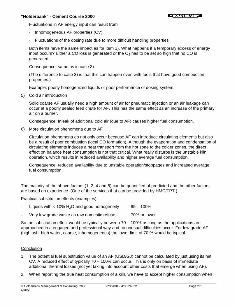
"Holderbank" - Cement Course 2000
© Holderbank Management & Consulting, 2000 6/23/2001 - 4:35:26 PM Page 270Query:
Fluctuations in AF energy input can result from
- Inhomogeneous AF properties (CV)
- Fluctuations of the dosing rate due to more difficult handling properties
Both items have the same impact as for item 3). What happens if a temporary excess of energyinput occurs? Either a CO loss is generated or the O2 has to be set so high that no CO isgenerated.
Consequence: same as in case 3).
(The difference to case 3) is that this can happen even with fuels that have good combustionproperties.)
Example: poorly homogenized liquids or poor performance of dosing system.
5) Cold air introduction
Solid coarse AF usually need a high amount of air for pneumatic injection or an air leakage canoccur at a poorly sealed feed chute for AF. This has the same effect as an increase of the primaryair on a burner.
Consequence: Inleak of additional cold air (due to AF) causes higher fuel consumption.
6) More circulation phenomena due to AF
Circulation phenomena do not only occur because AF can introduce circulating elements but alsobe a result of poor combustion (local CO formation). Although the evaporation and condensation ofcirculating elements induces a heat transport from the hot zone to the colder zones, the directeffect on balance heat consumption is not that critical. What really disturbs is the unstable kilnoperation, which results in reduced availability and higher average fuel consumption.
Consequence: reduced availability due to unstable operation/stoppages and increased averagefuel consumption.
The majority of the above factors (1, 2, 4 and 5) can be quantified of predicted and the other factorsare based on experience. (One of the services that can be provided by HMC/TPT.)
Practical substitution effects (examples):
- Liquids with < 10% H2O and good homogeneity 95 – 100%
- Very low grade waste as raw domestic refuse 70% or lower
So the substitution effect would be typically between 70 – 100% as long as the applications areapproached in a engaged and professional way and no unusual difficulties occur. For low grade AF(high ash, high water, coarse, inhomogeneous) the lower limit of 70 % would be typical.
Conclusion
1. The potential fuel substitution value of an AF (USD/GJ) cannot be calculated by just using its netCV. A reduced effect of typically 70 – 100% can occur. This is only on basis of immediateadditional thermal losses (not yet taking into account other costs that emerge when using AF).
2. When reporting the true heat consumption of a kiln, we have to accept higher consumption when
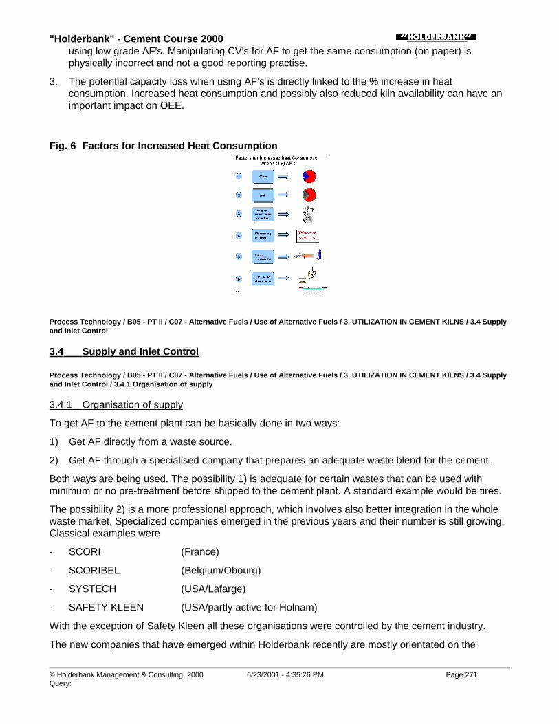
"Holderbank" - Cement Course 2000
© Holderbank Management & Consulting, 2000 6/23/2001 - 4:35:26 PM Page 271Query:
using low grade AF's. Manipulating CV's for AF to get the same consumption (on paper) isphysically incorrect and not a good reporting practise.
3. The potential capacity loss when using AF’s is directly linked to the % increase in heatconsumption. Increased heat consumption and possibly also reduced kiln availability can have animportant impact on OEE.
Fig. 6 Factors for Increased Heat Consumption
Process Technology / B05 - PT II / C07 - Alternative Fuels / Use of Alternative Fuels / 3. UTILIZATION IN CEMENT KILNS / 3.4 Supplyand Inlet Control
3.4 Supply and Inlet Control
Process Technology / B05 - PT II / C07 - Alternative Fuels / Use of Alternative Fuels / 3. UTILIZATION IN CEMENT KILNS / 3.4 Supplyand Inlet Control / 3.4.1 Organisation of supply
3.4.1 Organisation of supply
To get AF to the cement plant can be basically done in two ways:
1) Get AF directly from a waste source.
2) Get AF through a specialised company that prepares an adequate waste blend for the cement.
Both ways are being used. The possibility 1) is adequate for certain wastes that can be used withminimum or no pre-treatment before shipped to the cement plant. A standard example would be tires.
The possibility 2) is a more professional approach, which involves also better integration in the wholewaste market. Specialized companies emerged in the previous years and their number is still growing.Classical examples were
- SCORI (France)
- SCORIBEL (Belgium/Obourg)
- SYSTECH (USA/Lafarge)
- SAFETY KLEEN (USA/partly active for Holnam)
With the exception of Safety Kleen all these organisations were controlled by the cement industry.
The new companies that have emerged within Holderbank recently are mostly orientated on the

"Holderbank" - Cement Course 2000
© Holderbank Management & Consulting, 2000 6/23/2001 - 4:35:27 PM Page 272Query:
SCORIBEL/Obourg model. From a technical viewpoint of a cement plant these companies provide thefollowing functions:
- Allocating adequate waste categories to the cement plant
- Control of properties
- Preparation/pretreatment(in particular blending/homogenising)
The preparation of waste into a useful cement kiln AF is done externally. This seems to become thepreferred approach. The supply companies within Holderbank have a common platform: the VESTAForum.
Process Technology / B05 - PT II / C07 - Alternative Fuels / Use of Alternative Fuels / 3. UTILIZATION IN CEMENT KILNS / 3.4 Supplyand Inlet Control / 3.4.2 Delivery control
3.4.2 Delivery control
A delivery control at the cement plant is essential. In case of hazardeous wastes this is anyway a must(given by the permit) and this does not need to be explained further.
What is less obvious is that even harmless or non-hazardeous AF’s need to be checked whendelivered to the cement plant. The problem is that AF’s can be contaminated with undesirableinpurities. Whether this happens intentionally or not, it needs to be excluded.
Examples:
♦ Waste oil
♦ The original motor oil would not be critical from its properties but the waste product that is finallydelivered to the cement plant may be contaminated, e.g. with
- Solvents (a small quantity of solvents decreases the flash point drastically and thus the safetycan become a problem)
- PCB (PCB contaminated oils have a high disposal fee and the cement kiln could be abused toget rid of them cheaply, PCB is not detectable by simple test methods)
♦ Waste tires
♦ When accepting waste tires it is mandatory to have a visual delivery control and the receiving areamust not allow uncontrolled access for various suppliers. Some plants that believed they could do itwithout any control finally paid a high price because they were abused as a dumping area for nonusable sizes, rims and other materials (for which they had to pay for the disposal).
♦
♦ Chlorine
♦ It happened from time to time that suppliers came up with new solid waste mixes (RDF) or mixedplastics where they claimed very low chlorine contents. This is not always true, but difficult todisprove. There is in fact a problem that sampling of solid RDF is hardly representative and thechlorine analysis are often lower than the average bulk. So do not believe, but check what you getfor chlorine, it could hurt your kiln operation.
Process Technology / B05 - PT II / C07 - Alternative Fuels / Use of Alternative Fuels / 3. UTILIZATION IN CEMENT KILNS / 3.4 Supply
"Holderbank" - Cement Course 2000
© Holderbank Management & Consulting, 2000 6/23/2001 - 4:35:27 PM Page 273Query:
and Inlet Control / 3.4.3 Check-list for Properties of Waste Fuels
3.4.3 Check-list for Properties of Waste Fuels
Table 2 Checklist for Properties of Waste Fuels
• Type of waste Name, trade name origin
• Physical state: solid liquid gaseous solid/liquid
Size, form, grindability viscosity at ...°C, impuritiesmixing proportions
• Density kg/m3
• Calorific value (net) MJ/kg
• Proximate analysis Moisture, ash, volatiles, Cfix
• Ultimate analysis C, H, O, N, S
• Halogens Cl, Br, F
• Ash composition CaO, SiO2, Al2O3, Fe2O3, K2O, Na2O,P2O5, etc
• Heavy metals Hg, Cd, Tl, Be, As, Co, Cr, Pb, Zu, V,etc.
• Flashpoint °C
• Explosivity non-explosive
• Toxicity toxic /non toxic, safety precautions,warnings
• Legal restrictions containingtransport and storage
• Storage Chemical or natural degradation,putrefaction phenomena,segregations, precipitations,
• Corrosivity Construction materials required
• Mixing possibilities Mixing with oil, water, solvents
• Quantities to be used min, max, average (now, in future)
• Fluctuations in quality Quality specification
Process Technology / B05 - PT II / C07 - Alternative Fuels / Use of Alternative Fuels / 4. EMISSIONS IN CONTEXT WITHALTERNATIVE FUELS
4. EMISSIONS IN CONTEXT WITH ALTERNATIVE FUELS

"Holderbank" - Cement Course 2000
© Holderbank Management & Consulting, 2000 6/23/2001 - 4:35:27 PM Page 274Query:
Process Technology / B05 - PT II / C07 - Alternative Fuels / Use of Alternative Fuels / 4. EMISSIONS IN CONTEXT WITHALTERNATIVE FUELS / 4.1 Introduction
4.1 Introduction
If alternative fuels are used to substitute conventional fuels the cement kiln emissions are often notincreased and may even drop.
Fig. 6 Emission influence AF
Emissions do occur but they are hardly caused by alternative fuels. Emission results mainly from theraw material and from the high temperature process (NOx) and the fuels have only a limited influence.E.g. the SO2 emission on a suspension preheater kiln does not depend on the sulfur in the fuel. Thedifficult part can be how to handle the normal emissions if burning AF’s attracts public interest andimplies more stringent emission rules.
Process Technology / B05 - PT II / C07 - Alternative Fuels / Use of Alternative Fuels / 4. EMISSIONS IN CONTEXT WITHALTERNATIVE FUELS / 4.2 General Features of Cement Kiln Systems
4.2 General Features of Cement Kiln Systems
"Barriers" which prevent toxic substances from being emitted or becoming harmful to the environment(see figure 7)
Fig. 7 Environmental Aspects: „Emission Barriers“

"Holderbank" - Cement Course 2000
© Holderbank Management & Consulting, 2000 6/23/2001 - 4:35:29 PM Page 275Query:
# 1 High incineration temperature
In the sintering zone flame temperatures of some 2000°C are required for process reasons. Even verystable organic compounds (e.g. PCB) are completely destroyed.
This argument does not apply for secondary firings.
# 2 Contact with Fine, Dispersed Raw Meal
Intensive contact of gas and raw meal is required for process reasons (heat transfer). This producesgas purification through absorption of toxic compounds while contact occurs in counter-current pattern.Excellent retention of acid gases (e.g. HCl, SO2) and also of most of the heavy metals is achieved inSP-preheaters and raw mills. The key is the contact of gas with fine suspended particles.
This does not apply for the bypass gas extraction, which must be considered e.g. in an emissionestimate.
# 3 Low Final Gas Temperature (favourable equilibrium)
Condensation or absorption on surface active raw meal reduces the concentrations of toxic elementsaccording to the physical/chemical equilibrium. This effect strongly depends on the gas temperature.The lower the stack temperature the lower will be the equilibrium concentrations of the vapours of toxiccompounds. Examples for very low stack temperatures are:
♦ Kiln gas after passing the raw mill (during combined operation) ~ 100°C
♦ It is therefore possible to keep emission levels low, while the gases are passing the raw mill(argument #2 and #3 are equally important).
♦
# 4 Efficient Dedusting Equipment
The high absorption capacity of the kiln system avoids emissions but on the other hand can causeenrichments of the filter dust for certain elements that can reach the outer dust cycle (e.g. Tl). Anefficient dedusting prevents enriched dust from getting into the atmosphere. Also no EP shut offs areacceptable. Moreover, excessive dust emissions have an over proportional negative psychologicalimpact as all neighbours can see it.

"Holderbank" - Cement Course 2000
© Holderbank Management & Consulting, 2000 6/23/2001 - 4:35:29 PM Page 276Query:
# 5 Safe Disposal of Trace Elements
Trace elements or heavy metals cannot be destroyed nor can they disappear. If they are fed into thecement clinkering process and are not emitted they must have an outlet. Unlike other incinerationsystems, which produce concentrated and often toxic by-products, a cement kiln with complete dustreintroduction offers the unique possibility to incorporate trace elements in the clinker production indiluted and immobile form. These trace elements occur in concentrations which are usually notdifferent from clinker, which is produced without alternative fuels and they are not leachable (exception:hexavalent Cr during make up with water).
If the dust is not completely reintroduced into the kiln or if a bypass is required the above argument - inits simple form - is no longer true.
Process Technology / B05 - PT II / C07 - Alternative Fuels / Use of Alternative Fuels / 4. EMISSIONS IN CONTEXT WITHALTERNATIVE FUELS / 4.3 Special rules regarding emission behaviour on cement kilns
4.3 Special rules regarding emission behaviour on cement kilns
♦ The reality with emission is usually too complex for a safe and accurate prediction. However, froman engineering point of view it is better to have some ideas or rules about the emission behaviourto roughly identify what could be critical or not.
♦ Low emission of Cl, F and Br, < 0.1% of balance input.
♦ Low volatile heavy metals are not critical. Emission usually < 0.1% of balance inputs.
♦ Medium or high volatile heavy metals can reach the outer dust cycle (Cd, Tl) or even escape inform of vaporous compounds (Hg). Whereas Cd and Tl are still below < 1% emission Hg can beemitted almost totally (again this depends on process conditions).
♦ SO2 emissions are not depending on fuel sulfur in case of a SP kiln. Wet kilns however show amoderate influence by S on emissions.
♦ AF burning in the secondary firing usually decreases the NOx (0 – 30%).
♦ CO as discussed previously is often increased when using the secondary firing. Fluctuating energyinput may also cause CO peaks.
♦ Virtually no organics result from AF burning (even in cases of CO formation it does not necessarilycorrelate with organics). The improper use of AF via kiln feed is of course excluded from thisconsideration.
♦ Dioxine/furan emissions on SP kilns are not critical in view of a limit of 0.1 ng TE/m3. Again, there isno correlation with AF burning.
Process Technology / B05 - PT II / C07 - Alternative Fuels / Use of Alternative Fuels / 5. ADVANTAGES / DISADVANTAGES
5. ADVANTAGES / DISADVANTAGES
Nowadays the destruction of wastes in special incineration plants is being improved e.g. by addition ofmore effective gas cleaning. Under this aspect the question may arise whether it still makes sense toincinerate wastes in cement kilns instead of in special incinerators. To answer this question theadvantages and disadvantages of a cement kiln must be compared as follows:

"Holderbank" - Cement Course 2000
© Holderbank Management & Consulting, 2000 6/23/2001 - 4:35:29 PM Page 277Query:
Advantages Disadvantages
Possibility of high temperatureincineration (up to 2000°C) whichdestroys toxic organic compoundcompletely
The majority of heavy metals can becaptured at > 99.9% in the kiln system(absorption by raw meal)
Some limitations have to beconsidered, e.g. Hg, Tl, Cr
Acid gases are retained efficiently(e.g. no HCl emission)
Because of kiln internal circulationphenomena, cement kilns andespecially SP-kilns cannot accept highinputs of chlorine
No solid residues occur because theash is incorporated in the clinker. Nolandfill is required
In the case of wet kilns or bypassinstallations solid residues in the formof dust may need disposal
If the necessary rules are observedthere will be no influence onemissions and clinker quality
For psychological reasons somecustomers may not accept cementwhich is produced by using „waste“
No necessity for a new incineratorsince the cement kiln is alreadyexisting
High environmental awareness helpsto allocate certain wastes to cementplants
Realization of a project may be difficultand time consuming at the level ofpublic discussion and obtaining ofpermission
Process Technology / B05 - PT II / C07 - Alternative Fuels / Use of Alternative Fuels / 6. PRACTICAL APPLICATIONS
6. PRACTICAL APPLICATIONS
Process Technology / B05 - PT II / C07 - Alternative Fuels / Use of Alternative Fuels / 6. PRACTICAL APPLICATIONS / 6.1 Waste Tires
6.1 Waste Tires
Energy potential
♦ Calorific value (depends on quantity of steel included) 28 to 32 MJ/kg
Comparison for an industrialized country (per capita):
a) Energy required to burn clinker at500 kg cement/cap. a (at 3.6 MJ/kg) = 1800 MJ/a cap.
b) Energy from waste tires at

"Holderbank" - Cement Course 2000
© Holderbank Management & Consulting, 2000 6/23/2001 - 4:35:29 PM Page 278Query:
6 kg tires/cap. a (at 30 MJ/kg) = 180 MJ/a cap.
Theoretical overall fuel replacement(if tires were fully available for cement industry) 10%
Conclusion:
Tires are an important energy source and so far the most frequent application of AF. The practicalattractivity depends on the disposal fee that is available. Current values (in different areas) range from0 – 60 USD/t.
Typical Composition of Tires
Constituents
Rubber 36.0%
Filler (soot, SiO2) 37.0%
ZnO 1.2%
Softeners 3.0%
Sulfur 1.3%
Steel, textiles 18.0%
Rest 3.5%
Total 100%
Chemical analysis
C 70%
H 7%
S 1 ...3%
Cl 0.2...0.6%
Fe 15%
ZnO 2%
SiO2 + rest 5%
Cr 97 ppm
Ni 77 ppm
Pb 60 to 760 ppm
Cd 5 to 10 ppm
Tl 0.2 to 0.3 ppm
"Holderbank" - Cement Course 2000
© Holderbank Management & Consulting, 2000 6/23/2001 - 4:35:30 PM Page 279Query:
Incineration in Cement Kilns
Incineration of waste tires in cement kilns has nowadays become a frequent method. At least 40cement plants are known to do so. They can usually substitute 10 - 20% of their fuel requirements.
From an environmental point of view this method is considered as proven and advantageous(energetical recycling, low emission, no solid residues). It is often well accepted by the authorities.
Application of feeding methods:
1) Whole tiresThis is the most frequent application, based on the secondary firing principle. Originally, this wasfirst developed and used on dry SP-kilns but then also extended to long dry or wet kilns.
♦ a) Kiln inlet of suspension preheater kilns A feed system according to the figure 8 involves an investment of some USD 2 Mio. for a fully automatic installation.
♦ b) Mid kiln introduction device on long dry or wet kilns The principle is similar to a) but the introduction chute is rotating with the kiln shell, i.e. the tire feed is coupled with the kiln revolution. Figure 9 shows the introduction chute of the "Cadence" system as used at the Joliette plant.
2) Shredded tires / TDFTDF = tire derived fuel
♦ Shredded tires allow for a more regular fuel input into the kiln and have a higher density(advantages for transport and storage).
♦ Shredding costs are some 30 - 60 UDS/t. Sometimes this is already paid by disposal fees.Shredding is normally not operated by the cement producer.
♦ The use of shredded tires < 300 mm on suspension preheater kilns as in figure 10 is rare becauseit would cost less to use complete tires at the kiln inlet.
♦ The use of shredded tires < 50 mm has some applications on long kilns in North America wherestill many long dry and wet kilns are in operation. The tire chips are injected into the burning zone.Figure 11 shows the example of the Seattle plant with 15% substitution. Shredded tires or TDF <50 mm are successfully used on precalciners according to figure 12 in the plants Midlothian,Theodore, Ramos Arizpe and Lägerdorf.
3) Ground tires (< 5 mm):Theoretically, ground tires would be the ideal fuel for any primary firing (without compromise).However, the costs for grinding are usually prohibitive. Ground rubber as granulate is normally tooexpensive as fuel. Nevertheless, a Group Plant in Germany and HCB have tried this and gonethrough a learning process.
4) Pyrolisis/Gazification of tires:The Japanese have realised gasifications for cement kilns and reported more than a decade ago.It was based on a reactor (shaft) with understochiometric air addition at 700°C. The hot gasproduced was directly sent to the cement kiln.
♦ 1999 a new gasifier for whole tires (industrial scale) was commissioned by Polysius at JuraCement in Wildegg (Switzerland). The hot combustible gases are used in the precalciner.Investment for a 3 t/h installation is in the order of 3 Mio. USD. (Fig. 13)

"Holderbank" - Cement Course 2000
© Holderbank Management & Consulting, 2000 6/23/2001 - 4:35:30 PM Page 280Query:
♦ The gasification can potentially help to optimize the use of tires, which still needs to bedemonstrated on a long-term basis. The costs are significantly higher than for burning the tiresdirectly. Direct burning - not gasification - should always be the first option to be investigated.
♦
Fig. 8 Whole Tire Handling and Lump Fuel Kiln Feed (HCB-Eclépens)
Fig. 9 “Cadence valve” on Joliette kiln
Fig. 10 Handling of Tyre Chips and Lump Alternative Fuels at Altkirch
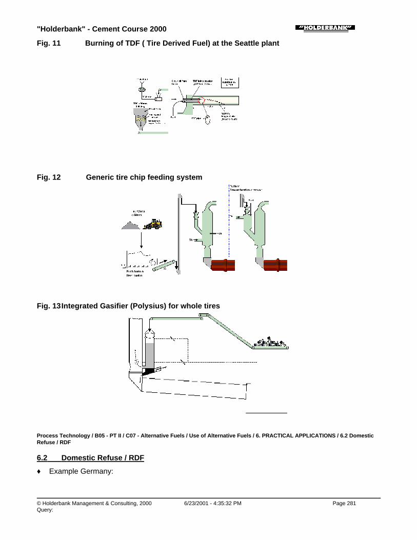
"Holderbank" - Cement Course 2000
© Holderbank Management & Consulting, 2000 6/23/2001 - 4:35:32 PM Page 281Query:
Fig. 11 Burning of TDF ( Tire Derived Fuel) at the Seattle plant
Fig. 12 Generic tire chip feeding system
Fig. 13 Integrated Gasifier (Polysius) for whole tires
Process Technology / B05 - PT II / C07 - Alternative Fuels / Use of Alternative Fuels / 6. PRACTICAL APPLICATIONS / 6.2 DomesticRefuse / RDF
6.2 Domestic Refuse / RDF
♦ Example Germany:

"Holderbank" - Cement Course 2000
© Holderbank Management & Consulting, 2000 6/23/2001 - 4:35:38 PM Page 282Query:
Domestic refuse Cementconsumption
Quantity 400 kg/cap a 450 kg/cap a
Energy content 3.4 GJ/cap a 1.7 GJ/cap a
(heat energy)
♦ The energy content contained in the domestic refuse is twice the energy consumption of thecement!
♦ However, a complete use of the energy from raw domestic refuse in the cement industry is by nomeans feasible. Reasons:
• poor homogeneity, inadequate size, difficult handling
• Cl-content of 0.5...1% Cl which can cause clogging problems in the kiln
• low calorific value (8 to 10 MJ/kg)
• low density and high transport costs per heat unit
• competition to existing incinerators
Conclusion:
Domestic refuse needs intensive processing in order to eliminate undesired fractions and to obtain areasonable burnable fraction. Such a fraction may represent 30...50% of the original refuse, the restneeds further disposal. The burnable fraction is called RDF (refuse derived fuel) and offers somewhatbetter properties, e.g. a CV of 12...16 MJ/kg.
Experience:
The first application was in the early 80’s at BCI/Westbury, now stopped.
The most important application today is the Wittekind plant in Erwitte (Germany) according to figure 14with 50% substitution and a chlorine bypass. Otherwise very few plants have realized majorapplications.
Fig. 14 Processing of Domestic Refuse and Incineration of RDF in a SP Kiln
Process Technology / B05 - PT II / C07 - Alternative Fuels / Use of Alternative Fuels / 6. PRACTICAL APPLICATIONS / 6.3 Burning ofContaminated Waste Oil

"Holderbank" - Cement Course 2000
© Holderbank Management & Consulting, 2000 6/23/2001 - 4:35:40 PM Page 283Query:
6.3 Burning of Contaminated Waste Oil
The burning of waste oil in cement kilns has a long tradition. In the late 80’s and early 90’s new effortshave been made to investigate the influence of contaminants. Extensive measurement programs havebeen performed to demonstrate all possible impacts on the environment.
Important examples come from Germany and Austria.
One of the first plants to publish the results of its measurements in 1988 was Phoenix inBeckum/Germany. They burnt waste oil, which was contaminated with PCB (0 to 1000 ppm).Emissions of dioxins were also measured. This project was 50% sponsored by the GermanUmweltbundesamt (UBA).
The Lägerdorf plant and the Gmunden plant (Austria) have also followed this at an even higher degreeof perfection. The design of the original Lägerdorf installation is shown in the figure 15. A largeprogram of measurements has been done and published. This program also includes emissionmeasurements of SO2, NOx, heavy metals, F, chlorinated organics, PCB, Dioxins/Furans. It could bedemonstrated that a limit for dioxins of 0.1 ng TE/m3 (toxic equivalent) could be easily met and thatthese emissions are not influenced by burning contaminated waste oils. A similar result was obtainedat Gmunden.
Special efforts were also made with regard to the delivery control, which meant a considerableextension to the existing laboratory. Limiting values for the waste oil in Gmunden:
Pb < 5000 ppm
Hg < 2 ppm
Tl < 10 ppm
Cd < 60 ppm
PCB < 100 ppm
F < 600 ppm
S < 5%
Cl < 1%
N < 5%
H2O < 15%
Sediments < 5%
CV net > 25’000 kJ/kg
The original installation Lägerdorf according to figure 15 is designed for low flashpoints (< 21°C),therefore, use of solvents is also possible.
Fig. 15 Burning of Waste Oil at Lägerdorf Plant

"Holderbank" - Cement Course 2000
© Holderbank Management & Consulting, 2000 6/23/2001 - 4:35:40 PM Page 284Query:
Process Technology / B05 - PT II / C07 - Alternative Fuels / Use of Alternative Fuels / 6. PRACTICAL APPLICATIONS / 6.4 Burningpure waste oil
6.4 Burning pure waste oil
The installation from Untervaz according to figure 16 results from a former heavy oil system and isadequate for high quality waste oil with high flashpoint (> 55°C).
Fig. 16 Handling of Waste Oil at BCU Untervaz
Process Technology / B05 - PT II / C07 - Alternative Fuels / Use of Alternative Fuels / 6. PRACTICAL APPLICATIONS / 6.5 Burning ofWaste Wood at Rekingen
6.5 Burning of Waste Wood at Rekingen
This installation to process waste wood to a dry saw dust and burn it in a cement kiln went intooperation in 1994. It was stopped in 1997 because the Rekingen plant was closed (market reasons).The final stage of this project would have been 70’000 t/a of processed waste wood or 50% fuelsubstitution. The treatment of the incoming wood consisted of delivery control, primary crushing,sorting fine grinding and drying.
The projected costs were 25 Mio. Swiss Francs and therefore among the highest ever realized for asingle project for an AF. During the project phase the fees for waste wood were overestimated. When itcame into operation, the actual market prices for waste wood were much lower and the installationcould not be amortized.

"Holderbank" - Cement Course 2000
© Holderbank Management & Consulting, 2000 6/23/2001 - 4:35:44 PM Page 285Query:
Fig. 17 Use of Waste Wood as Fuel at the Rekingen Plant
Process Technology / B05 - PT II / C07 - Alternative Fuels / Use of Alternative Fuels / 6. PRACTICAL APPLICATIONS / 6.6 Mixedexamples
6.6 Mixed examples
The following illustrations originate from our reports describing practical AFR applications in our Groupplants. The illustrations are self-explaining.
Content:
- Liquid AF at Altkirch
- Liquid AF at Obourg
- Distillation Residues and Animal Fat at Untervaz
- Mid kiln firing for bales at Obourg
- Dried Sewage Sludge and Animal Meal at Untervaz
- Solid AF (Impregnated saw dust) at Eclépens
- Tire Chips and Ferrocarbon at Lägerdorf
- Fly ash at Lägerdorf
Fig. 18 Handling of Liquid Alternative Fuels (CSL) at Altkirch(Solvents, Oil-Emulsions, Pasty Liquids)

"Holderbank" - Cement Course 2000
© Holderbank Management & Consulting, 2000 6/23/2001 - 4:35:46 PM Page 286Query:
Fig. 19 Handling of Solvents (CSL: Combustible de SubstitutionLiquide) at Ciments d’Obourg
Fig. 20 Handling of Destillation Residue and Animal Fat at BCU Untervaz
Fig. 21 Mid Kiln Installation at Ciments d’Obourg

"Holderbank" - Cement Course 2000
© Holderbank Management & Consulting, 2000 6/23/2001 - 4:35:48 PM Page 287Query:
Fig. 22 Handling of Dried Sewage Sludge and Animal Meal at Untervaz
Fig. 23 Handling and injecting of solid fuel at “HCB Eclépens (impregnatedsaw dust, shredded plastic, animal meal)
Fig. 24 Handling of Tire Chips and Ferrocarbon at Lägerdorf
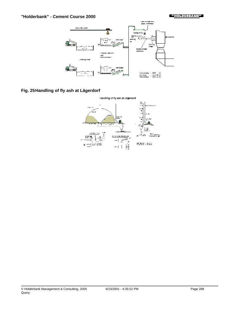
"Holderbank" - Cement Course 2000
© Holderbank Management & Consulting, 2000 6/23/2001 - 4:35:52 PM Page 288Query:
Fig. 25 Handling of fly ash at Lägerdorf
"Holderbank" - Cement Course 2000
© Holderbank Management & Consulting, 2000 6/23/2001 - 4:35:54 PM Page 289Query:
Process Technology / B05 - PT II / C07 - Alternative Fuels / Preparation of Alternative Fuels
Preparation of Alternative FuelsA. FlacherPT 00/14667/E
1. INTRODUCTION
2. FROM WASTE TO ALTERNATIVE FUEL
2.1 Waste Properties
2.2 Processing of Waste
3. LIQUID ALTERNATIVE FUEL PREPARATION
3.1 Pollution of Liquid Waste
3.2 Homogenizing
3.3 Safety
4. PREPARATION OF ALTERNATIVE FUEL FROM PASTY WASTE
4.1 High Viscosity Liquid Facility
4.2 Impregnation Facility
5. SOLID ALTERNATIVE FUEL PREPARATION
5.1 Shredding and Granulation of Solid Waste
6. EXAMPLES
6.1 Typical Liquid Waste Handling
6.2 SCORIBEL Impregnated Sawdust Production
6.3 Industrial Plastic Waste Shredding at PLASTREC AG
SUMMARY
Alternative fuels used in the cement manufacturing process originate from waste, which often doesn’thave suitable physical properties for the kiln process. This is where alternative fuel preparation isneeded.
This paper focuses on common waste treatment techniques for alternative fuel production. For acomplete understanding of the subject, the lecture of the Cement Course paper “Use of AlternativeFuels“ is recommended.
Process Technology / B05 - PT II / C07 - Alternative Fuels / Preparation of Alternative Fuels / 1. INTRODUCTION
1. INTRODUCTION
Waste is a residual product of some sort of process. Its physical properties are characterized by this

"Holderbank" - Cement Course 2000
© Holderbank Management & Consulting, 2000 6/23/2001 - 4:35:54 PM Page 290Query:
process. Alternative fuel, on the other hand, is a combustible for clinker manufacture. It must havephysical properties suited for incineration in a cement kiln. In many cases the properties of waste andalternative fuel do not correspond. This is where alternative fuel preparation is required.
Process Technology / B05 - PT II / C07 - Alternative Fuels / Preparation of Alternative Fuels / 2. FROM WASTE TO ALTERNATIVEFUEL
2. FROM WASTE TO ALTERNATIVE FUEL
Process Technology / B05 - PT II / C07 - Alternative Fuels / Preparation of Alternative Fuels / 2. FROM WASTE TO ALTERNATIVEFUEL / 2.1 Waste Properties
2.1 Waste Properties
When waste material is considered for alternative fuel use, first of all, its chemical composition(circulating elements, ash composition) must be suited for the kiln process. Then there are otherproperties and aspects, which need to be looked at:
♦ The viscosity of liquid waste determines the design of the storage and handling installation.
♦ Corresponding to the granulometry of solid waste, a size reduction process might have to beconsidered and the suitable kiln feeding point is chosen.
♦ Water contained in liquids requires mixing for better homogeneity of the alternative fuel. Watercontained in solid waste has an impact on the handling as it might change the flowability of thematerial.
♦ Foreign bodies and impurities need to be separated in order to reduce wear and the risk ofblockages.
♦ Safety is very important when dealing with waste, e.g. toxicity and flashpoint need to beconsidered.
♦ Additional aspects refer to the waste supply, such as annual tonnage as well as form andschedule of delivery.
Process Technology / B05 - PT II / C07 - Alternative Fuels / Preparation of Alternative Fuels / 2. FROM WASTE TO ALTERNATIVEFUEL / 2.2 Processing of Waste
2.2 Processing of Waste
As for any other process, for the preparation of alternative fuel the most simple and inexpensive butalso safe process is suited best. A mechanical waste treatment is therefore chosen in almost any case.
Similar to the mechanical processes in cement manufacture the preparation of alternative fuelcomprises of the following main processes:
♦ Screening to separate foreign and oversized material which might cause handling or wearproblems in fuel preparation and firing installations.
♦ Size reduction to fit the fuel to the foreseen firing point (e.g. preheater, main burner), as well as toallow a proper dosing and to ensure a good combustion.

"Holderbank" - Cement Course 2000
© Holderbank Management & Consulting, 2000 6/23/2001 - 4:35:54 PM Page 291Query:
♦ Homogenizing and mixing to feed to the kiln process a fuel of constant quality.
Picture 1 gives and overview of the different processes from waste to alternative fuel. Explanation isgiven in the following chapters.
Picture 1: Processes from waste to alternative fuel
Thermal waste processing (gasification/pyrolysis) is applied in a few cement plants. It is operated inconjunction with the kiln. Gasification allows separating the combustible fraction of a waste in agaseous form from the non-combustible part. The investment cost for such installation is comparablyhigh, which makes this process worthwhile only when considerable disposal fees are received.
Process Technology / B05 - PT II / C07 - Alternative Fuels / Preparation of Alternative Fuels / 3. LIQUID ALTERNATIVE FUELPREPARATION
3. LIQUID ALTERNATIVE FUEL PREPARATION
In many cement plants, liquid waste has been the first waste material to be accepted and used asalternative fuel because little preparation is necessary and, in certain cases, existing installations maybe used. However, there are special aspects that need to be considered when handling liquid wastesuch as waste oil and solvents.
Process Technology / B05 - PT II / C07 - Alternative Fuels / Preparation of Alternative Fuels / 3. LIQUID ALTERNATIVE FUELPREPARATION / 3.1 Pollution of Liquid Waste
3.1 Pollution of Liquid Waste
Liquid waste is likely to be polluted with foreign bodies (metal pieces, sand, plastics etc.). A coarsefiltering upon reception is therefore necessary. With in-line shredders and grinders remaining particlescan be crushed to avoid blockages. Even after a second filter in the kiln firing line, there are still solidparticles present in the liquid. The pumping and kiln injection system must therefore be designedaccordingly.
Picture 2: Screw pole pump, suited for waste oil containing solid particles

"Holderbank" - Cement Course 2000
© Holderbank Management & Consulting, 2000 6/23/2001 - 4:35:55 PM Page 292Query:
Process Technology / B05 - PT II / C07 - Alternative Fuels / Preparation of Alternative Fuels / 3. LIQUID ALTERNATIVE FUELPREPARATION / 3.2 Homogenizing
3.2 Homogenizing
Due to the presence of solids and often also mixtures of liquids with different densities, a mixing tank isrequired. A recirculation circuit or mechanical mixer ensures a good blending.
Process Technology / B05 - PT II / C07 - Alternative Fuels / Preparation of Alternative Fuels / 3. LIQUID ALTERNATIVE FUELPREPARATION / 3.3 Safety
3.3 Safety
The handling of solvents or liquid waste containing solvents represents a safety risk since there is ahigh potential for explosion. The decisive parameter for the safe design of a liquid installation is theliquid’s flashpoint (the flashpoint is the temperature at which the evaporations of a combustible liquidform an inflammable gas). Pure motor oil has a flashpoint of up to 200°C whereas other liquids, suchas solvents, can have one below 0°C.
Another safety risk to workers and the environment represent toxic substances. Special protection andsafety procedures are required. The guideline for this should always be the safety standards applied inthe chemical industry.
Picture 3: Protected worker sampling liquid waste

"Holderbank" - Cement Course 2000
© Holderbank Management & Consulting, 2000 6/23/2001 - 4:35:55 PM Page 293Query:
Process Technology / B05 - PT II / C07 - Alternative Fuels / Preparation of Alternative Fuels / 4. PREPARATION OF ALTERNATIVEFUEL FROM PASTY WASTE
4. PREPARATION OF ALTERNATIVE FUEL FROM PASTY WASTE
In industrial areas there are often considerable amounts of pasty or sludgy waste materials available,such as
♦ resin, paint, varnish
♦ oil sludges from tank cleaning
♦ destillation residues
♦ grease, soap.
Many of these materials are hazardous. With regard to the variable clinker production cost, they cantherefore be of particular interest as considerable disposal fees may be received.
From the point of view of incineration, it is important that such waste is burnt at high temperatures withsufficient residence time (The combustion criteria for destruction of halogenated waste for example is1‘200 °C with 2 seconds residence time). This is only ensured at the main burner of a cement kiln.Therefore, the hazardous, pasty waste must be pre-treated for incineration in the primary firing.
There are two common ways of sludge pre-treatment for incineration in the primary firing, see below.For mainly non-hazardous sludges there is the possibility of kiln inlet feeding. With such application,the sludge is screened to take out coarse foreign bodies before being pumped to the kiln by means ofa concrete pump. Sludge feeding at the kiln inlet is limited due to the high water input.
Picture 4: Sludge feeding installation to kiln inlet (Apaxco plant)
Process Technology / B05 - PT II / C07 - Alternative Fuels / Preparation of Alternative Fuels / 4. PREPARATION OF ALTERNATIVEFUEL FROM PASTY WASTE / 4.1 High Viscosity Liquid Facility
4.1 High Viscosity Liquid Facility
A so-called high viscosity liquid facility aims to liquefy the sludgy waste. This is achieved by mixing thesludge with liquid fuel. The important aspect of this process is the compatibility of the substancesinvolved. To avoid chemical reaction, sludge and liquid need to fulfill certain requirements. This

"Holderbank" - Cement Course 2000
© Holderbank Management & Consulting, 2000 6/23/2001 - 4:35:55 PM Page 294Query:
however, limits the use of such pre-treatment system to certain substances, which is a drawback withregard to flexibility.
Process Technology / B05 - PT II / C07 - Alternative Fuels / Preparation of Alternative Fuels / 4. PREPARATION OF ALTERNATIVEFUEL FROM PASTY WASTE / 4.2 Impregnation Facility
4.2 Impregnation Facility
The other common sludge pre-treatment process aims to prepare a pourable, fine, solid alternativefuel. This is achieved by mixing the sludges with an impregnation support. Saw dust is commonly usedfor this purpose. It has a good absorbency and the impregnated product shows little stickiness.Alternatively, filter cakes and also animal meal have been used as impregnation aid.
In what follows the different steps of an impregnation facility are explained.
Process Technology / B05 - PT II / C07 - Alternative Fuels / Preparation of Alternative Fuels / 4. PREPARATION OF ALTERNATIVEFUEL FROM PASTY WASTE / 4.2 Impregnation Facility / 4.2.1 Reception and Preparation of Primary Materials
4.2.1 Reception and Preparation of Primary Materials
The sludgy waste is delivered either in bulk or small containers (typically 200 l steel drums) andemptied into pits. There are drums, which cannot be emptied by gravity or reasonable manual effort.For such containers a robust shredding facility is needed.
Picture 5: Drum emptying
According to chemical analysis of the incoming waste and the product requirements, the unloadedmaterials are mixed and then shredded. The prepared mix is conveyed to a mixing station by means ofa high pressure pump.
For an optimum product quality and minimum use of impregnation aid the viscosity of the batch mix isadjusted. If necessary, liquid phases are extracted from the drums or added to the mixing pit.
Process Technology / B05 - PT II / C07 - Alternative Fuels / Preparation of Alternative Fuels / 4. PREPARATION OF ALTERNATIVEFUEL FROM PASTY WASTE / 4.2 Impregnation Facility / 4.2.2 Production of Impregnated Alternative Fuel and Dispatch
4.2.2 Production of Impregnated Alternative Fuel and Dispatch
Once there is a batch of sludge prepared it needs to be mixed with sawdust. The mixing ratio is aboutone third of saw dust and two thirds of sludge.
For a simple installation, it is possible to mix the components by means of a wheel loader. The moresophisticated process is to use a continuously operated intensive mixer.

"Holderbank" - Cement Course 2000
© Holderbank Management & Consulting, 2000 6/23/2001 - 4:35:56 PM Page 295Query:
Legend:
1: mixing container2: mixing tool3: material guiding arm4: discharge opening5: housing
Picture 6: Intensive mixer (type Eirich)
Before storage, metals are separated and the product is screened in a drum screen. The product isfine (mostly – 10 mm) and well suited for incineration at the main firing.
For storage moving floor type silos are best suited.
Process Technology / B05 - PT II / C07 - Alternative Fuels / Preparation of Alternative Fuels / 4. PREPARATION OF ALTERNATIVEFUEL FROM PASTY WASTE / 4.2 Impregnation Facility / 4.2.3 Organic Emission
4.2.3 Organic Emission
Due to the handling of unconfined chemicals there is a lot of organic emission. This requires anappropriate protection of the workforce on the one hand. On the other hand, an aspiration and thermaltreatment of the emission might be necessary.
Process Technology / B05 - PT II / C07 - Alternative Fuels / Preparation of Alternative Fuels / 5. SOLID ALTERNATIVE FUELPREPARATION
5. SOLID ALTERNATIVE FUEL PREPARATION
Solid waste can be fed in a coarse form to the kiln (e.g. whole tyres) but often needs to have a finergranulometry. A size reduction is necessary and determined mainly by the following process factors:
♦ transportation cost
♦ handling properties
♦ kiln feeding point
♦ thermal substitution rate

"Holderbank" - Cement Course 2000
© Holderbank Management & Consulting, 2000 6/23/2001 - 4:35:56 PM Page 296Query:
♦ kiln behavior.
The mechanical processes used for the size reduction of solid waste are shredding and granulation.They are typically applied for materials such as wood, rubber, plastics or waste tyres.
Process Technology / B05 - PT II / C07 - Alternative Fuels / Preparation of Alternative Fuels / 5. SOLID ALTERNATIVE FUELPREPARATION / 5.1 Shredding and Granulation of Solid Waste
5.1 Shredding and Granulation of Solid Waste
Process Technology / B05 - PT II / C07 - Alternative Fuels / Preparation of Alternative Fuels / 5. SOLID ALTERNATIVE FUELPREPARATION / 5.1 Shredding and Granulation of Solid Waste / 5.1.1 Shredders
5.1.1 Shredders
A shredder is a machine for primary size reduction of solid materials. Its operating principle is based ona tearing and shearing action of slowly rotating tools (10 – 40 rpm) agitated by a high torque drive.
Picture 7: Typical shredder design with two counterrotating shafts
Typically, a shredder consists of two counterrotating shafts. On these shafts engaging disks with hooktype knives are mounted to grab and tear the material fed. Such shredder is preferably used for thesize reduction of high-density waste (e.g. wood and tyres). Waste materials with a low bulk densitysuch as plastic films require a shredder with large feed opening and a mechanism to push the materialtowards the cutting rotor. For such application single rotor shredders are used.
Depending on the knife size and operation (multiple stage, closed circuit) a minimum chip size of 20 –50 mm can be achieved.
Process Technology / B05 - PT II / C07 - Alternative Fuels / Preparation of Alternative Fuels / 5. SOLID ALTERNATIVE FUELPREPARATION / 5.1 Shredding and Granulation of Solid Waste / 5.1.2 Granulators
5.1.2 Granulators
Granulators (also called grinders) are generally used for secondary size reduction. The typical designconsists of a single rotor with a fixed counter knife and an outlet sieve. There is a mechanism to pushwaste material towards the rotor where knives grab it. After being cut at the fixed counter knife thewaste chips are further milled before they pass the outlet sieve. A granulator operates at higher rpmthan a shredder, above about 100 rpm.
Picture 8: Typical granulator design with one shaft and outlet sieve

"Holderbank" - Cement Course 2000
© Holderbank Management & Consulting, 2000 6/23/2001 - 4:35:57 PM Page 297Query:
Due to their high rotor speed, granulators are used for low abrasive material. Waste containingconsiderable amounts of metals and/or mineral material should not be granulated because ofexcessive wear. The spacing between the rotor knife and the fixed counter knife needs to be small(about 0.5 mm) to efficiently cut fine material like plastic films.
Process Technology / B05 - PT II / C07 - Alternative Fuels / Preparation of Alternative Fuels / 5. SOLID ALTERNATIVE FUELPREPARATION / 5.1 Shredding and Granulation of Solid Waste / 5.1.3 Multi-Stage Size Reduction
5.1.3 Multi-Stage Size Reduction
For the firing of waste materials at the preheater/precalciner, a single stage size reduction is sufficientin most cases. If bulky waste material is to be fired at the main burner a multiple stage shredding andgranulation is required for the efficient production of an alternative fuel of a few millimeter size.
Process Technology / B05 - PT II / C07 - Alternative Fuels / Preparation of Alternative Fuels / 6. EXAMPLES
6. EXAMPLES
Process Technology / B05 - PT II / C07 - Alternative Fuels / Preparation of Alternative Fuels / 6. EXAMPLES / 6.1 Typical LiquidWaste Handling
6.1 Typical Liquid Waste Handling
A typical handling facility for the reception of liquid waste and the production of liquid alternative fuel isshown in picture 9.
The installation consists of the following main elements:
♦ Liquid waste decanting tank with primary filtration
♦ Shredder to crush oversized particles for protection of the pump and to avoid blockages.
♦ Discharge pump, typically of centrifugal type
♦ Liquid storage tank with mechanical mixer
♦ Loading pump, typically of centrifugal type
♦ In case of low flashpoint liquid, a nitrogen inertisation system

"Holderbank" - Cement Course 2000
© Holderbank Management & Consulting, 2000 6/23/2001 - 4:35:59 PM Page 298Query:
♦ Sprinkling system for fire suppression
Picture 9: Typical liquid waste handling installation
Process Technology / B05 - PT II / C07 - Alternative Fuels / Preparation of Alternative Fuels / 6. EXAMPLES / 6.2 SCORIBELImpregnated Sawdust Production
6.2 SCORIBEL Impregnated Sawdust Production
SCORIBEL is a Belgium based subsidiary of Ciments d’Obourg. At the impregnation workshop of itsSeneffe plant solid, pasty and liquid waste is mixed with an impregnation aid to form a fine, solidalternative fuel for incineration at the main firing of cement kilns.
The installation consists of three main parts:
♦ A reception section for industrial waste in bulk or containers as well as the impregnation aidssawdust and filter cake. In a closed building the liquid, pasty and solid waste is premixed andshredded.
♦ By means of a continuously operated intensive mixer the waste sludge is mixed with theimpregnation aid before being screened.
♦ In two moving floor type silos the product is stored and homogenized before being loaded to trucks.
For reduction of organic emission air is aspirated at the main sources of emission and sent to a thermaltreatment unit.
The plant’s design production capacity is 15 t/h, actually it is operated at more than 20 t/h.
Investment cost for the impregnation facility (excl. air treatment): BEF 250 Mio.
Picture 10: flowsheet of SCORIBEL’s impregnation workshop

"Holderbank" - Cement Course 2000
© Holderbank Management & Consulting, 2000 6/23/2001 - 4:36:01 PM Page 299Query:
Process Technology / B05 - PT II / C07 - Alternative Fuels / Preparation of Alternative Fuels / 6. EXAMPLES / 6.3 Industrial PlasticWaste Shredding at PLASTREC AG
6.3 Industrial Plastic Waste Shredding at PLASTREC AG
PLASTREC AG, a subsidiary of HCB, operates a facility for the shredding of industrial plastic andrubber waste to a product for use at the primary firing of cement kilns. The waste materials receivedare cables, textile reinforced plastic, residues from manufacture of hard plastic items, plastic films andrubber.
The facility is designed to mechanically process the incoming waste to a product of 10 mm size. This isachieved by pre-shredding and subsequent grinding of the material. Two shredders and twogranulators, each operated in parallel, are used for the two-stage process. Material transport is doneby belt conveyors for raw and pre-shredded material, and pneumatically for the finished product.
The plant has an hourly production rate of 1.5 – 2.0 t. The annual production is about 5‘000 t. Theconsumption of electrical energy is 100 kWh/t for the whole facility.
Investment cost for whole installation: CHF 1.2 Mio.
Picture 11: flowsheet of PLASTREC plastic shredding plant

"Holderbank" - Cement Course 2000
© Holderbank Management & Consulting, 2000 6/23/2001 - 4:36:04 PM Page 300Query:
Process Technology / B05 - PT II / C08 - Circulation Phenomena
C08 - Circulation Phenomena

"Holderbank" - Cement Course 2000
© Holderbank Management & Consulting, 2000 6/23/2001 - 4:36:04 PM Page 301Query:
Process Technology / B05 - PT II / C08 - Circulation Phenomena / Circulation Phenomena in the Clinkerization Process
Circulation Phenomena in the Clinkerization ProcessRené Hasler, Daniel BrasselPT 99/14503/E
1. INTRODUCTION
2. MECHANISM OF THE CIRCULATION PHENOMENA
3. CIRCULATING ELEMENTS IN THE KILN SYSTEM
3.1 Input of Circulating Elements
3.2 Enrichment of Circulating Elements / Endangered Zones for Encrustation Formation
3.3 Output of Circulating Elements
3.4 Volatility of Circulating Elements
3.5 Condensation of Circulating Elements
4. TYPICAL APPEARANCE OF BUILD-UPS
5. KILN OPERATION PROBLEMS DUE TO CIRCULATING ELEMENTS
6. IDENTIFICATION OF PROBLEMS WITH ENCRUSTATIONS AND BUILD-UPS
6.1 Material Balance
6.2 Criteria and Indicators to Assess the Build-up Problem
6.3 Example of a Circulation Phenomena Problem
7. MEASURES AGAINST BUILD-UP FORMATION
7.1 General Measures
7.2 “Intelligent“ Cleaning
7.3 Measures against Chloride Problems
7.4 Measures against Sulfur Problems
7.5 Measures against Alkali Problems
8. MATHEMATICAL MODEL TO SIMULATE THE CYCLES OF THE CIRCULATING ELEMENTS

"Holderbank" - Cement Course 2000
© Holderbank Management & Consulting, 2000 6/23/2001 - 4:36:05 PM Page 302Query:
SUMMARY
This chapter describes the circulation of volatile elements in the kiln system. It indicates the tolerableinputs of circulating elements so that no excessive build-up and clogging problems arise.
In particular it shall serve as guideline how an encrustation problem, caused by volatile elements, issystematically solved.
Process Technology / B05 - PT II / C08 - Circulation Phenomena / Circulation Phenomena in the Clinkerization Process / 1.INTRODUCTION
1. INTRODUCTION
Alkali, sulfur and chlorine compounds (hereafter called circulating or volatile elements, see below) inraw materials and fuels utilized for the cement manufacture, when present in high concentrations oftengiven rise to difficulties in kiln operation with build-up formation, mainly in the preheater and the kilninlet section.
Volatile Elements (VE):
Sulfur SO3
Potassium K2O
Sodium Na2O
Chlorine Cl
The build-up formations cause cyclone blockages or restrictions of the kiln inlet area so that the kilnhas to be stopped for cleaning. In extreme cases more than 200 annual kiln stops due to blockagesmay occur, so that the impact on kiln availability and productivity can become a severe issue.Suspension preheaters armed with dozens of shock blowers (Fig. 1a, 1b) to prevent build-up formationillustrate the importance of this problem.
Fig. 1a
Fig. 1b

"Holderbank" - Cement Course 2000
© Holderbank Management & Consulting, 2000 6/23/2001 - 4:36:05 PM Page 303Query:
Process Technology / B05 - PT II / C08 - Circulation Phenomena / Circulation Phenomena in the Clinkerization Process / 2.MECHANISM OF THE CIRCULATION PHENOMENA
2. MECHANISM OF THE CIRCULATION PHENOMENA
Depending on the degree of volatility, the circulating elements evaporate in the sintering zone of thecement kiln and are carried by the gases to colder zones, where they mainly condense on the rawmeal and partly also on the surrounding walls.
Afterwards they return with the raw meal into the sintering zone where they partly reevaporatedepending on the degree of volatility. This repeated process through the kiln leads to the establishmentof internal cycles (see Fig. 5). Finally the cycles reach equilibrium so that the output of circulatingelements is equal to their input by the raw materials and the fuels (cp. Fig. 2).
Fig. 2 Circulation of Volatile Elements within the Kiln System
Almost all the circulating elements finally leave the system with the clinker. However, this is only thecase when beforehand sufficiently high internal cycles of the volatile elements have been formed. Theextents of these cycles depend on the degree of volatility of the circulating elements. As the latterrecondense on the colder raw meal and the surrounding walls, the formed sticky molten salts are ableto reduce the fluidability of the raw meal and, if present in sufficient quantities, to glue it finally on thewalls. From time to time, especially during a change of the temperature profile, pieces of build-ups falldown and mainly block the cyclone outlets (Fig. 3).
Fig. 3 Build-ups due to Circulating Elements in the Various Kiln Systems

"Holderbank" - Cement Course 2000
© Holderbank Management & Consulting, 2000 6/23/2001 - 4:36:05 PM Page 304Query:
If the amount of molten salts becomes too high, either because of an excessive input of volatileelements or due to a high degree of volatility, the installation of a kiln gas bypass becomes necessaryin order to extract part of the circulating elements from the kiln system (Fig. 4a, 4b, 4c).
Fig. 4a Conventional Bypass with Water Injection
Fig. 4b Hot Gas Bypass without Water Injection
Fig. 4c Bypass with Gas Feedback

"Holderbank" - Cement Course 2000
© Holderbank Management & Consulting, 2000 6/23/2001 - 4:36:06 PM Page 305Query:
A small part of the circulating elements leave the kiln system with the main exhaust gas dust. The latteris efficiently precipitated in the dedusting unit and is normally reintroduced into the kiln system. This iscalled the external cycle of the circulating elements (Fig. 5).
Fig. 5 Circulation Phenomena: Internal and External Cycle
In normal cases a negligible amount of circulating elements is emitted by the stack into theatmosphere. However, the emission of SO2 is not negligible anymore, when the sulfur in the rawmaterial is present in form of sulfide (FeS2, PbS, ZnS) or organic compounds. In this latter case thesulfides are volatilized in the temperature range of 400 to 600°C and leave the kiln system partly asgaseous SO2 emission (Fig. 6 and section 3.3.4).
Fig. 6 SO2 Emission in case of Sulfides

"Holderbank" - Cement Course 2000
© Holderbank Management & Consulting, 2000 6/23/2001 - 4:36:06 PM Page 306Query:
Process Technology / B05 - PT II / C08 - Circulation Phenomena / Circulation Phenomena in the Clinkerization Process / 3.CIRCULATING ELEMENTS IN THE KILN SYSTEM
3. CIRCULATING ELEMENTS IN THE KILN SYSTEM
Process Technology / B05 - PT II / C08 - Circulation Phenomena / Circulation Phenomena in the Clinkerization Process / 3.CIRCULATING ELEMENTS IN THE KILN SYSTEM / 3.1 Input of Circulating Elements
3.1 Input of Circulating Elements
In the following the typical inputs of circulating elements by the raw materials and the fuel(s) areindicated. It is differentiated between input ranges where usually no encrustation and build-upproblems arise and input ranges that usually lead to severe clogging problems.
Important: All figures may serve as rough guidelines only. The real limits for the build-up and clogging formation depend on a lot of individualparameters like the degree of volatilization, the temperature profile, thecompleteness of combustion and the excess air factor as well as the kiln systemitself. The indicated values are guidelines for suspension preheater kiln only.
Process Technology / B05 - PT II / C08 - Circulation Phenomena / Circulation Phenomena in the Clinkerization Process / 3.CIRCULATING ELEMENTS IN THE KILN SYSTEM / 3.1 Input of Circulating Elements / 3.1.1 Input by the Raw Materials (loss freebasis)
3.1.1 Input by the Raw Materials (loss free basis)
♦ Alkalis (K, Na):Generally appear as interlayer cations in the clay minerals and the feldspars.
♦ Sulfur:The sulfur is introduced in several mineralogical forms:
• as sulfate: gypsum CaSO4 ⋅ 2H2O anhydrate CaSO4
• as sulfide: pyrite FeS2, organic compoundsIn the following only the sulfates are considered.
♦ Chlorine:The chlorides are mainly introduced as NaCl (from seawater) or KCl.
Note: The„kiln feed“ normally includes already external cycle (see Fig. 2) so that its concentration oncirculating elements is higher than the one of the pure raw mix.
Typical limits for 4 to 5 stage SP kilns are listed in section 6.2.2.
Process Technology / B05 - PT II / C08 - Circulation Phenomena / Circulation Phenomena in the Clinkerization Process / 3.CIRCULATING ELEMENTS IN THE KILN SYSTEM / 3.1 Input of Circulating Elements / 3.1.2 Input by the Fuel(s)
3.1.2 Input by the Fuel(s)
Mainly sulfur is introduced by the fuels such as Coal, Coke, fuel oil and so on. In Addition alternativefuels often contain a reasonable amount of sulfur.
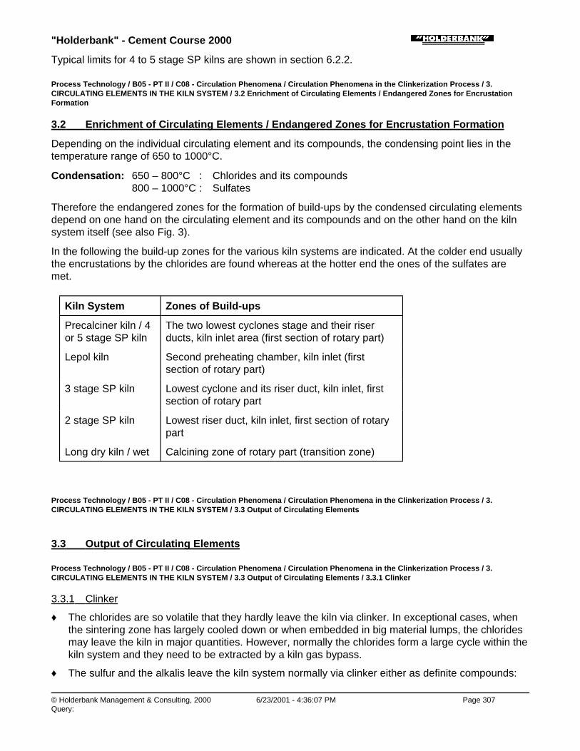
"Holderbank" - Cement Course 2000
© Holderbank Management & Consulting, 2000 6/23/2001 - 4:36:07 PM Page 307Query:
Typical limits for 4 to 5 stage SP kilns are shown in section 6.2.2.
Process Technology / B05 - PT II / C08 - Circulation Phenomena / Circulation Phenomena in the Clinkerization Process / 3.CIRCULATING ELEMENTS IN THE KILN SYSTEM / 3.2 Enrichment of Circulating Elements / Endangered Zones for EncrustationFormation
3.2 Enrichment of Circulating Elements / Endangered Zones for Encrustation Formation
Depending on the individual circulating element and its compounds, the condensing point lies in thetemperature range of 650 to 1000°C.
Condensation: 650 – 800°C : Chlorides and its compounds 800 – 1000°C : Sulfates
Therefore the endangered zones for the formation of build-ups by the condensed circulating elementsdepend on one hand on the circulating element and its compounds and on the other hand on the kilnsystem itself (see also Fig. 3).
In the following the build-up zones for the various kiln systems are indicated. At the colder end usuallythe encrustations by the chlorides are found whereas at the hotter end the ones of the sulfates aremet.
Kiln System Zones of Build-ups
Precalciner kiln / 4or 5 stage SP kiln
The two lowest cyclones stage and their riserducts, kiln inlet area (first section of rotary part)
Lepol kiln Second preheating chamber, kiln inlet (firstsection of rotary part)
3 stage SP kiln Lowest cyclone and its riser duct, kiln inlet, firstsection of rotary part
2 stage SP kiln Lowest riser duct, kiln inlet, first section of rotarypart
Long dry kiln / wet Calcining zone of rotary part (transition zone)
Process Technology / B05 - PT II / C08 - Circulation Phenomena / Circulation Phenomena in the Clinkerization Process / 3.CIRCULATING ELEMENTS IN THE KILN SYSTEM / 3.3 Output of Circulating Elements
3.3 Output of Circulating Elements
Process Technology / B05 - PT II / C08 - Circulation Phenomena / Circulation Phenomena in the Clinkerization Process / 3.CIRCULATING ELEMENTS IN THE KILN SYSTEM / 3.3 Output of Circulating Elements / 3.3.1 Clinker
3.3.1 Clinker
♦ The chlorides are so volatile that they hardly leave the kiln via clinker. In exceptional cases, whenthe sintering zone has largely cooled down or when embedded in big material lumps, the chloridesmay leave the kiln in major quantities. However, normally the chlorides form a large cycle within thekiln system and they need to be extracted by a kiln gas bypass.
♦ The sulfur and the alkalis leave the kiln system normally via clinker either as definite compounds:

"Holderbank" - Cement Course 2000
© Holderbank Management & Consulting, 2000 6/23/2001 - 4:36:07 PM Page 308Query:
♦ K2SO4, K3Na(SO4), Na2SO4
Ca2K2(SO4)3
CaSO4 (rare!)
♦ or in solid solution in clinker minerals:K with the Belite, AluminateNa with the AluminateSO3 with the Belite
♦
♦ The calciumanhydrate CaSO4 is rather volatile (decomposes at temperatures > 1000°C) and formstherefore a large sulfur cycle in the kiln system. Therefore it is very important that there is sufficientalkalis to combine with the sulfur and to leave the kiln system as alkali/sulfur compound.
Process Technology / B05 - PT II / C08 - Circulation Phenomena / Circulation Phenomena in the Clinkerization Process / 3.CIRCULATING ELEMENTS IN THE KILN SYSTEM / 3.3 Output of Circulating Elements / 3.3.2 Kiln Gas Bypass
3.3.2 Kiln Gas Bypass
Kiln gas bypasses (see Fig. 4) are mainly used to extract the very volatile chlorides from SP preheaterkilns. Chloride bypasses withdraw typically 5 to 15% of the kiln gases. The hot gases from the kiln inletare quenched down by fresh air, sometimes supported by injection of water into the quench chamber,to a temperature below 600°C. The gaseous chlorides condense onto the withdrawn dust particles andare separated finally in an electrostatic precipitator or a bagfilter (see Fig. 5a, 5b, 5c).
In rare cases kiln gas bypasses are also applied in case of too much CaSO4 and not sufficient alkalis.
Also for the production of low alkali clinker large kiln gas bypasses are used (20 to 50% of the kilngases) in order to withdraw the alkalis from the kiln charge and to produce a clinker with an alkalicontent of < 0.6% (i.e. Na2Oeq < 0.6%). Thereby the alkalis are volatilized by hard burning and byinjection of chlorides into the kiln (see also section 0).
The bypass dust must be discarded e.g. into the quarry or is partly reutilized as additive to the cement,or in rare cases may be sold as filler material.A ballpark figure for the amount of bypass dust: 15 g/kg cli per 10% bypass
Due to the extraction of the bypass gases additional heat loss arise. The specific value per % bypassdepends on the kiln system:
• Precalciner kilns: 8 – 11 kJ/kg cli
• Preheater kilns: 20 kJ/kg cli
Typical chemical concentrations of bypass dusts are found in Fig. 7 and 8.
Process Technology / B05 - PT II / C08 - Circulation Phenomena / Circulation Phenomena in the Clinkerization Process / 3.CIRCULATING ELEMENTS IN THE KILN SYSTEM / 3.3 Output of Circulating Elements / 3.3.3 Kiln Dust
3.3.3 Kiln Dust
Another possibility to withdraw circulating elements from the kiln system is via external cycle (see Fig.5) which is interrupted and partly discarded. The enrichment of this kiln dust by circulating elementsdepends on the kiln system. Whereas kiln dusts from long wet kilns are highly enriched, the ones fromSP kilns show nearly the same chemical composition than the raw meal. Typical chemical

"Holderbank" - Cement Course 2000
© Holderbank Management & Consulting, 2000 6/23/2001 - 4:36:08 PM Page 309Query:
concentrations of dusts from the different kiln systems are shown on Fig. 7 and 8. Thereby thefollowing legend applies:
WL = long wet kiln
DL = long dry kiln
DG = dry kiln with grate preheater (LEPOL)
DS = SP kilns: F Filter dust from kiln exhaust gas
BP Bypass dust
Fig. 7 Kiln Dust Analyses
Fig. 8 Kiln Dust Analyses
Process Technology / B05 - PT II / C08 - Circulation Phenomena / Circulation Phenomena in the Clinkerization Process / 3.CIRCULATING ELEMENTS IN THE KILN SYSTEM / 3.3 Output of Circulating Elements / 3.3.4 Emission by Exhaust Gas
3.3.4 Emission by Exhaust Gas
Normally there is no emission of circulating elements by the exhaust gas. The only gaseouscomponent, the SO2 which does not condense at low temperatures is effectively absorbed by the freelime at the lowest cyclone stage.

"Holderbank" - Cement Course 2000
© Holderbank Management & Consulting, 2000 6/23/2001 - 4:36:08 PM Page 310Query:
However, a source of SO2 emission is the raw material sulfur in form of sulfide (e.g. pyrite). Thesulfides decompose at temperatures between 400 to 600°C, forming SO2. Approximately 70% of theSO2 immediately reacts with the CaCO3 of the kiln feed to CaSO3 and finally at higher temperatures toCaSO4. The residual 30% of the SO2 are partly absorbed on their way with the flue gases to the stack,mainly in the raw mill and in the conditioning tower. However, a certain portion of the SO2 is finallyemitted by the stack, depending on the kiln and raw mill system (see Fig. 6).
Process Technology / B05 - PT II / C08 - Circulation Phenomena / Circulation Phenomena in the Clinkerization Process / 3.CIRCULATING ELEMENTS IN THE KILN SYSTEM / 3.4 Volatility of Circulating Elements
3.4 Volatility of Circulating Elements
Process Technology / B05 - PT II / C08 - Circulation Phenomena / Circulation Phenomena in the Clinkerization Process / 3.CIRCULATING ELEMENTS IN THE KILN SYSTEM / 3.4 Volatility of Circulating Elements / 3.4.1 Definition of Total Volatility
3.4.1 Definition of Total Volatility
The total volatility of a circulating element or a compound of it is defined as shown in Fig. 9.
Fig. 9 The Volatility of a Circulating Element
The total volatility of a circulating element or of a compound of it indicates which portion of it isvolatilized in the kiln and does not leave the kiln straight with the clinker.
The total volatility is:
HM
cli
cc
−= 1ϕ
whereas ϕ = factor for total volatility cHM = concentration of the circulating element at the kiln inlet ccli = concentration of the circulating element in the clinker
Process Technology / B05 - PT II / C08 - Circulation Phenomena / Circulation Phenomena in the Clinkerization Process / 3.CIRCULATING ELEMENTS IN THE KILN SYSTEM / 3.4 Volatility of Circulating Elements / 3.4.2 Affinity of the Circulating Elements
3.4.2 Affinity of the Circulating Elements
Circulating elements have a strong affinity to other elements and form chemical compounds. The

"Holderbank" - Cement Course 2000
© Holderbank Management & Consulting, 2000 6/23/2001 - 4:36:09 PM Page 311Query:
following affinity order has been observed (see also Fig. 10):
1) The chlorine combines first with the alkalis, forming KCI, NaCl.The residual chlorine, if any, combines with the calcium, forming CaCl2.
2) The residual alkalis combine with the sulfur, forming K2SO4, Na2SO4. They form also double saltsCa2K2(SO4) 2, K3Na(SO4) 2.The residual alkalis, if any, combine with CO, forming K2CO3, Na2CO3.
3) The residual sulfur (SO3 or SO2) combines with CaO, forming CaSO4.
Fig. 10 Affinity
Process Technology / B05 - PT II / C08 - Circulation Phenomena / Circulation Phenomena in the Clinkerization Process / 3.CIRCULATING ELEMENTS IN THE KILN SYSTEM / 3.4 Volatility of Circulating Elements / 3.4.3 Volatility of the Circulating ElementCompounds
3.4.3 Volatility of the Circulating Element Compounds
Process Technology / B05 - PT II / C08 - Circulation Phenomena / Circulation Phenomena in the Clinkerization Process / 3.CIRCULATING ELEMENTS IN THE KILN SYSTEM / 3.4 Volatility of Circulating Elements / 3.4.3 Volatility of the Circulating ElementCompounds / 3.4.3.1 General
3.4.3.1 General
♦ In the kiln the alkalis are liberated from the clay mineral lattice. They partly dissociate into the gasphase and recombine with other elements according to the affinity order as described in paragraph3.4.2. The rest recombines directly in the charge material with chlorine or sulfur or is integrated intothe lattice of the clinker minerals (belite and aluminate, see paragraph 3.3.1). Especially the sodiumis little volatile and goes preferably direct into the clinker (Fig. 11).
Fig. 11 Circulation of Alkalis

"Holderbank" - Cement Course 2000
© Holderbank Management & Consulting, 2000 6/23/2001 - 4:36:09 PM Page 312Query:
The chlorides liberated during heating of the material and combustion of the fuel react with the alkalisto form alkali chloride. This reaction takes place either in the charge material or, after vaporization, in
the kiln gas (Fig. 12).
Fig. 12 Circulation of Chlorine
♦ Upon volatilization of sulfur at burning zone temperatures in the cement kiln, sulfur dioxide is thepredominant component. The gaseous SO2 derives either from the dissociated sulfur of thecombustibles or the decomposed CaSO4 and the partly volatilized Alk2SO4 from the chargematerial.
Subsequently if there is an excess of alkalis, the internal sulfur cycle is caused primarily by the reactionwith these, which takes place almost entirely in the rotary kiln. The alkali sulfates formed in thisreaction are, in so far as they are present in vapor form, precipitated on the material. This occursmainly in the rotary kiln itself, but partly also in the preheater.
The precipitated alkali sulfates thus travel through the kiln again, pass through the sintering zone, andare partly discharged from the kiln with the clinker, while some of the alkali sulfates remain in the cycle.
The calcium sulfate (CaSO4) is formed as a result of the reaction between SO2 and CaO. It is partlypresent already in the raw materials or is formed preferably in the temperature range of 800 to 900°Cas illustrated in Fig. 13. Above a temperature level of 1000°C the calcium sulfate starts decomposing,first rather slowly and beyond a temperature of 1300°C rapidly. Sulfur dioxide again is formed. If thealkali input is not high enough to combine the whole incoming sulfur as alkali sulfate, high sulfurdioxide concentrations in the kiln gas arise. In such circumstances calcium sulfate may passun-decomposed through the sintering zone leaving the kiln embedded in the belite mineral or even as

"Holderbank" - Cement Course 2000
© Holderbank Management & Consulting, 2000 6/23/2001 - 4:36:10 PM Page 313Query:
CaSO4. The sulfur cycle is illustrated in Fig. 14.
Fig. 13 SO2 Absorption by CaO resp. CaCO3
Fig. 14 Circulation of Sulfur
Process Technology / B05 - PT II / C08 - Circulation Phenomena / Circulation Phenomena in the Clinkerization Process / 3.CIRCULATING ELEMENTS IN THE KILN SYSTEM / 3.4 Volatility of Circulating Elements / 3.4.3 Volatility of the Circulating ElementCompounds / 3.4.3.2 Volatility of the Compounds of Circulating Elements
3.4.3.2 Volatility of the Compounds of Circulating Elements
Fig. 15 indicates the relation between vapor pressure of various alkali compounds at differenttemperatures. This demonstrates that the volatilization mechanism is dependent upon the form ofcombination of the particular volatile element.
Fig. 15 Vapor Pressure

"Holderbank" - Cement Course 2000
© Holderbank Management & Consulting, 2000 6/23/2001 - 4:36:10 PM Page 314Query:
Chlorides: KCl, NaCl, CaCl2
At a temperature level of 1200 to 1300°C the chlorides are already volatilized to a great extent. Atsintering zone temperatures they are almost entirely volatilized so that the total volatility factor ϕ isapprox. 0.97 to 1.
Sulfates: Alk2SO4, CaSO4
Basically, the Alk2SO4 are little volatile, whereas the CaSO4 is highly volatile.
Therefore the most important criteria for the total sulfur volatility is the molar ratio between the alkalisand the sulfur itself, corrected by the chlorine:
Molar alkali / sulfur ratio:
80
7162943
22
3SO
ClONaOK
SOAlk −+
=
Desirable value: 2.1
3
≈SOAlk
If there are sufficient alkalis available to combine with the total sulfur input (from raw materials as wellas from the fuel), the total volatility for the sulfur is ϕ = 0.3 to 0.5.
However, if there is a surplus of sulfur over the alkalis, the highly volatile CaSO4 is formed. Its volatilityis approximately ϕ = 0.9, but can increase up to ϕ = 1, depending on the operating conditions of theburning process.
In general the sulfur volatility is very much depending on the operating conditions of the burningprocess, such as
♦ the maximum temperature in the sintering zone
♦ the retention time of the kiln charge material at high sinter zone temperatures
♦ the granulometry of the kiln charge material (diffusion to the surface of the granules)
♦ the partial pressure of O2 in the kiln atmosphere
♦ the partial pressure of SO2 in the kiln atmosphere

"Holderbank" - Cement Course 2000
© Holderbank Management & Consulting, 2000 6/23/2001 - 4:36:10 PM Page 315Query:
For more details see next paragraph 3.4.4.
Process Technology / B05 - PT II / C08 - Circulation Phenomena / Circulation Phenomena in the Clinkerization Process / 3.CIRCULATING ELEMENTS IN THE KILN SYSTEM / 3.4 Volatility of Circulating Elements / 3.4.4 Parameters Influencing the Volatilityof the Sulfur Compounds
3.4.4 Parameters Influencing the Volatility of the Sulfur Compounds
Process Technology / B05 - PT II / C08 - Circulation Phenomena / Circulation Phenomena in the Clinkerization Process / 3.CIRCULATING ELEMENTS IN THE KILN SYSTEM / 3.4 Volatility of Circulating Elements / 3.4.4 Parameters Influencing the Volatilityof the Sulfur Compounds / 3.4.4.1 Maximum Temperature in the Sintering Zone
3.4.4.1 Maximum Temperature in the Sintering Zone
The essential feature of the volatility - temperature curve is that above a certain critical temperature thevolatility increases first exponentially and then slowly reaches a maximum (Fig. 16).
Fig. 16 Volatility-Temperature Curve
For sulfur this critical temperature is in the order of the burning temperature. Consequently hardburnable raw mixes or overheating of the kiln charge material (low free limes in the clinker) have a very
important bearing on sulfur volatility.
Process Technology / B05 - PT II / C08 - Circulation Phenomena / Circulation Phenomena in the Clinkerization Process / 3.CIRCULATING ELEMENTS IN THE KILN SYSTEM / 3.4 Volatility of Circulating Elements / 3.4.4 Parameters Influencing the Volatilityof the Sulfur Compounds / 3.4.4.2 Retention Time of the kiln Charge Material at High Burning Temperatures
3.4.4.2 Retention Time of the kiln Charge Material at High Burning Temperatures
Volatilization of the sulfur compounds is a dynamic process. The longer the kiln charge material isexposed to the high burning temperatures, the higher the total amount of volatilized sulfur.
Process Technology / B05 - PT II / C08 - Circulation Phenomena / Circulation Phenomena in the Clinkerization Process / 3.CIRCULATING ELEMENTS IN THE KILN SYSTEM / 3.4 Volatility of Circulating Elements / 3.4.4 Parameters Influencing the Volatilityof the Sulfur Compounds / 3.4.4.3 Granulometry of the Kiln Charge Material
3.4.4.3 Granulometry of the Kiln Charge Material
If the kiln charge material is well granulated, the sulfur takes more time to diffuse to the surface of thegranule. Consequently less sulfur volatilizes.
On the other hand poor granulometry conditions result in higher dust formation which negativelyinfluences the temperature profile in the kiln and shifts it towards the kiln inlet.
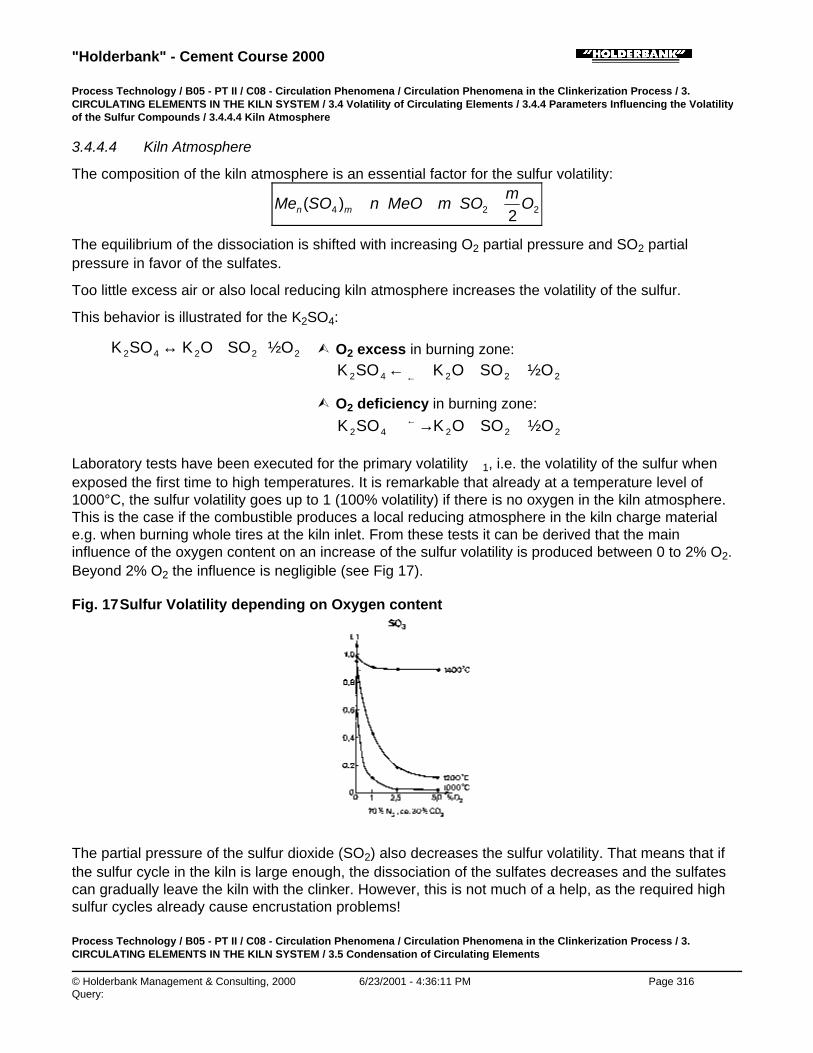
"Holderbank" - Cement Course 2000
© Holderbank Management & Consulting, 2000 6/23/2001 - 4:36:11 PM Page 316Query:
Process Technology / B05 - PT II / C08 - Circulation Phenomena / Circulation Phenomena in the Clinkerization Process / 3.CIRCULATING ELEMENTS IN THE KILN SYSTEM / 3.4 Volatility of Circulating Elements / 3.4.4 Parameters Influencing the Volatilityof the Sulfur Compounds / 3.4.4.4 Kiln Atmosphere
3.4.4.4 Kiln Atmosphere
The composition of the kiln atmosphere is an essential factor for the sulfur volatility:
224 2)( O
mSOmMeOnSOMe mn +⋅+⋅⇔
The equilibrium of the dissociation is shifted with increasing O2 partial pressure and SO2 partialpressure in favor of the sulfates.
Too little excess air or also local reducing kiln atmosphere increases the volatility of the sulfur.
This behavior is illustrated for the K2SO4:
22242 O½SOOKSOK ++↔ Ù O2 excess in burning zone:
22242 O½SOOKSOK ++← ←
Ù O2 deficiency in burning zone:
22242 O½SOOKSOK ++→←
Laboratory tests have been executed for the primary volatility ∈1, i.e. the volatility of the sulfur whenexposed the first time to high temperatures. It is remarkable that already at a temperature level of1000°C, the sulfur volatility goes up to 1 (100% volatility) if there is no oxygen in the kiln atmosphere.This is the case if the combustible produces a local reducing atmosphere in the kiln charge materiale.g. when burning whole tires at the kiln inlet. From these tests it can be derived that the maininfluence of the oxygen content on an increase of the sulfur volatility is produced between 0 to 2% O2.Beyond 2% O2 the influence is negligible (see Fig 17).
Fig. 17 Sulfur Volatility depending on Oxygen content
The partial pressure of the sulfur dioxide (SO2) also decreases the sulfur volatility. That means that ifthe sulfur cycle in the kiln is large enough, the dissociation of the sulfates decreases and the sulfatescan gradually leave the kiln with the clinker. However, this is not much of a help, as the required highsulfur cycles already cause encrustation problems!
Process Technology / B05 - PT II / C08 - Circulation Phenomena / Circulation Phenomena in the Clinkerization Process / 3.CIRCULATING ELEMENTS IN THE KILN SYSTEM / 3.5 Condensation of Circulating Elements
"Holderbank" - Cement Course 2000
© Holderbank Management & Consulting, 2000 6/23/2001 - 4:36:11 PM Page 317Query:
3.5 Condensation of Circulating Elements
As previously stated, the circulating elements volatilize in the hot zones of the kiln and condense at thecolder areas of the kiln system (internal cycle).
Melting point and boiling point (at 1 bar) of some chlorides, sulfates and carbonates are listed below.Generally speaking it can be stated that the chlorides condense at lower temperatures than thesulfates.
Melting Point [°C] Boiling Point [°C] at 1 bar
Chlorides NaCl 801 1413
KCl 776 1500 (sublim.)
CaCl2 772 > 1600
Sulfates Na2SO4 884 ?
K2SO4 1069 1689
CaSO4 1280 (d) -
Carbonates Na2CO3 851 (decomp.)
K2CO3 891 (decomp.)
In the melting phase secondary compounds are formed which are more complex than the originalvolatile elements:
Secondary Compounds:
Chlorides Sulfates Carbonates Spurrites
KCl K2SO4 K2CO3, 2 C2S ⋅ CaCO3
(NaCl) K3Na (SO4)2 (Na2CO3) 2 C2S ⋅ CaSO4
Na2SO4
Ca2K2 (SO4)3
CaSO4
Furthermore, investigations have revealed that calcium sulfate, calcium oxide and alkali sulfate formeutectic melts which can have much lower melting temperatures than the single compounds (Fig. 18).Under presence of chlorides these melting temperatures are even more lowered to temperatures below700°C. Very low melting temperatures show also the alkali carbonates. However, in such a case thealkalis can be sulfatizated by the addition of gypsum so that it presents normally not a major problem.
Fig. 18 Melt Intervals in the System

"Holderbank" - Cement Course 2000
© Holderbank Management & Consulting, 2000 6/23/2001 - 4:36:12 PM Page 318Query:
CaSO4 - K2SO4 - Na2SO4
All these melts, when present in sufficient quantities, lead to severe encrustations and build-upformation in the preheater and kiln inlet area.
A further problem is given by the fact that the volatilization process goes along with an endothermicreaction whereas the condensation is exothermic. By this way an important amount of heat is drawnfrom the sintering zone to the kiln inlet so that the area of condensation is shifted even more towardsthe cold end of the kiln system.
Process Technology / B05 - PT II / C08 - Circulation Phenomena / Circulation Phenomena in the Clinkerization Process / 4. TYPICALAPPEARANCE OF BUILD-UPS
4. TYPICAL APPEARANCE OF BUILD-UPS
Typical appearance of build-ups and deposits are shown in Fig. 19, 20 and 21.
Fig. 19 Macrographs of Deposit Types
Fig. 20 a) .. d) S.E.M. Micrographs of Deposits
Fig. 20 a) REM 84/506HD - 1st cyclone: KCl blocks embedded in fine matrix

"Holderbank" - Cement Course 2000
© Holderbank Management & Consulting, 2000 6/23/2001 - 4:36:12 PM Page 319Query:
Fig. 20 b) REM 84/525HD - 2nd cyclone: CaSO4 and C2S
Fig. 20 c) REM 84/502HV - 4th cyclone: Binding nature of glassy KCl matrix
Fig. 20 d) REM 84/550GM - 4th cyclone: KCl crystal structure filling pore

"Holderbank" - Cement Course 2000
© Holderbank Management & Consulting, 2000 6/23/2001 - 4:36:13 PM Page 320Query:
Fig. 21 a) .. d) S.E.M. Micrographs of Deposits
Fig. 21 a) REM 84/113TU - Riser pipe: CaSO4 and C2S
Fig. 21 b) REM 84/117TU - Riser pipe: K2SO4 and Ca SO4 border
Fig. 21 c) REM 84/72WU - Kiln inlet: Fly ash balls

"Holderbank" - Cement Course 2000
© Holderbank Management & Consulting, 2000 6/23/2001 - 4:36:13 PM Page 321Query:
Fig. 21 d) REM 84/69WU - Kiln inlet: Primary spurrite
Process Technology / B05 - PT II / C08 - Circulation Phenomena / Circulation Phenomena in the Clinkerization Process / 5. KILNOPERATION PROBLEMS DUE TO CIRCULATING ELEMENTS
5. KILN OPERATION PROBLEMS DUE TO CIRCULATING ELEMENTS
The consequences due to high internal cycles of the circulating elements are rather severe.
First it starts by an increased encrustation and build-up formation at the kiln inlet area and the lowerpart of the preheater. As a consequence the pressure loss across the system increases and at thesame time also the inbleeding false air quantity increases. This reduces the maximum kiln draft andthus the maximum clinker production. When the kiln operator tries to compensate the lower availablekiln draft by a lower excess air rate, the situation becomes even worse as the sulfur cycle furtherincreases.
Studies have revealed that a high chloride cycle impedes also complete combustion. This in turnfurther increases the sulfur cycle.
High sulfur cycles lead to a poorly granulated clinker and therefore to dust formation. The dust entrainsthe heat from the burning zone to the kiln inlet, so that the cycles of the volatile elements furtherincrease due to a longer residence time at high temperatures.
Furthermore, the high cycles of volatile elements transport the heat of the sintering zone to the area of

"Holderbank" - Cement Course 2000
© Holderbank Management & Consulting, 2000 6/23/2001 - 4:36:14 PM Page 322Query:
condensation by the endothermic - exothermic reactions, causing the same effect as the dust cyclesdescribed above.
The result of these mechanisms is always the same:
♦ Frequent kiln stops due to encrustation and clogging problems, i.e. reduced kilnutilization factor (⌫ reduction of OEE)
♦ Reduction of the maximum kiln production
♦ Higher heat consumption
♦ Formation of unstable coating at the transition zone and thus high refractoryconsumption
Process Technology / B05 - PT II / C08 - Circulation Phenomena / Circulation Phenomena in the Clinkerization Process / 6.IDENTIFICATION OF PROBLEMS WITH ENCRUSTATIONS AND BUILD-UPS
6. IDENTIFICATION OF PROBLEMS WITH ENCRUSTATIONS AND BUILD-UPS
Chlorides, sulfates, alkalis or any combination of them can cause encrustation and build-up problems.Therefore a detailed analysis is a prerequisite to find an appropriate solution.
The analysis can consist of eight steps as follows:
À Systematic analysis of the hot meal (cp section 6.1)(every shift: LOI, SO3, Cl, K2O, Na2O)
Á Comparison with the defined limits of circulating elements in the hot meal!Ù Chlorine problem, sulfur problem, alkali problem of combination?
 Performing of a material balance with the inputs and outputs of the circulating elements (cp section6.1).٠Where do the circulating elements come from?
à Comparison with typical tolerable inputs of circulating elements by raw materials and fuels.٠Which amount is critical?
Ä Calculation of the molar alkali / sulfur ratio and comparison with standard.Ù Are there enough alkali present to withdraw the sulfur within the clinker?
Å Calculation of the sulfur volatility and comparison with the standard.Ù Why sulfur problem?: ⌫ too high inputs? ⌫ unfavorable alkali / sulfur ratio? ⌫ because of kiln operation?
Æ Detailed recording where the build-ups occur and possible a chemical analysis of a typical build-uppeace.
Ç Specific measures against build-up formation (see section 7).
Process Technology / B05 - PT II / C08 - Circulation Phenomena / Circulation Phenomena in the Clinkerization Process / 6.IDENTIFICATION OF PROBLEMS WITH ENCRUSTATIONS AND BUILD-UPS / 6.1 Material Balance
6.1 Material Balance
♦ Definition of the balance boundary (Fig. 22):
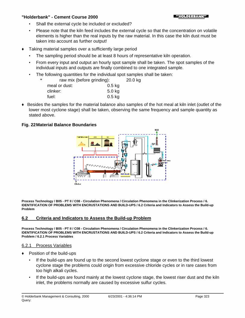
"Holderbank" - Cement Course 2000
© Holderbank Management & Consulting, 2000 6/23/2001 - 4:36:14 PM Page 323Query:
• Shall the external cycle be included or excluded?
• Please note that the kiln feed includes the external cycle so that the concentration on volatileelements is higher than the real inputs by the raw material. In this case the kiln dust must betaken into account as further output!
♦ Taking material samples over a sufficiently large period
• The sampling period should be at least 8 hours of representative kiln operation.
• From every input and output an hourly spot sample shall be taken. The spot samples of theindividual inputs and outputs are finally combined to one integrated sample.
• The following quantities for the individual spot samples shall be taken:∗ raw mix (before grinding): ∼ 20.0 kg
meal or dust: ∼ 0.5 kgclinker: ∼ 5.0 kgfuel: ∼ 0.5 kg
♦ Besides the samples for the material balance also samples of the hot meal at kiln inlet (outlet of thelower most cyclone stage) shall be taken, observing the same frequency and sample quantity asstated above.
Fig. 22 Material Balance Boundaries
Process Technology / B05 - PT II / C08 - Circulation Phenomena / Circulation Phenomena in the Clinkerization Process / 6.IDENTIFICATION OF PROBLEMS WITH ENCRUSTATIONS AND BUILD-UPS / 6.2 Criteria and Indicators to Assess the Build-upProblem
6.2 Criteria and Indicators to Assess the Build-up Problem
Process Technology / B05 - PT II / C08 - Circulation Phenomena / Circulation Phenomena in the Clinkerization Process / 6.IDENTIFICATION OF PROBLEMS WITH ENCRUSTATIONS AND BUILD-UPS / 6.2 Criteria and Indicators to Assess the Build-upProblem / 6.2.1 Process Variables
6.2.1 Process Variables
♦ Position of the build-ups
• If the build-ups are found up to the second lowest cyclone stage or even to the third lowestcyclone stage the problems could origin from excessive chloride cycles or in rare cases fromtoo high alkali cycles.
• If the build-ups are found mainly at the lowest cyclone stage, the lowest riser dust and the kilninlet, the problems normally are caused by excessive sulfur cycles.

"Holderbank" - Cement Course 2000
© Holderbank Management & Consulting, 2000 6/23/2001 - 4:36:15 PM Page 324Query:
♦ Completeness of combustion
• CO at kiln inlet > 0.1% and/or O2 < 1.5 to 2% cause high sulfur cycles.
• If no secondary firing or precalcination is applied also the CO and O2 concentrations afterpreheater can be taken to judge the completeness of combustion (CO must be < 0.1% and O2usually 3 to 4%, depending on the inbleeding amount of false air).
♦ Temperature profile
• Excessive temperatures within and after the preheater indicate a disturbed temperature profilein the rotary kiln and thus a too high sulfur volatilization.
♦ Pressure profile
• The pressure profile over the preheater indicates where the build-ups are located.
Process Technology / B05 - PT II / C08 - Circulation Phenomena / Circulation Phenomena in the Clinkerization Process / 6.IDENTIFICATION OF PROBLEMS WITH ENCRUSTATIONS AND BUILD-UPS / 6.2 Criteria and Indicators to Assess the Build-upProblem / 6.2.2 Material Balance
6.2.2 Material Balance
First a material balance must be performed as described in paragraph 6.1. Afterwards, the followingevaluation shall be done:
♦ Input of circulating elements
• It has to be determined in which form the sulfur is present in the raw materials, as sulfate orsulfide. When present as sulfide, part of it will leave the kiln system as emission via exhaustgas stack! Therefore the sulfur emission by the stack has to be deducted from the overall sulfurwhen judging a potential sulfur problem in the kiln.
• The inputs of circulating elements (without emitted sulfur through the stack!) should becompared to the ones given below in order to check whether they are in a normal range whereusually no build-ups are formed or whether they are too high. This, of course, is only a roughguideline.
Typical Input Limits for Circulating Elements (for 4 to 5 stage SP kiln only)
♦ Raw Material
(loss free basis)
Cl < 0.02% Normal case, no problems
> 0.05% Heavy clogging problems, depending on the sulfur cycle
SO3 1) < 0.5% Normal case, no problems
> 1.25% Heavy clogging problems
K2O < 1.0% Normal case, no problems
> 1.5% Problems with encrustations, depending on degree of sulfatization(molar alkali/sulfur ratio)
"Holderbank" - Cement Course 2000
© Holderbank Management & Consulting, 2000 6/23/2001 - 4:36:15 PM Page 325Query:
Na2O Little volatile, thus no problems due to recirculation of Na2O
1) Sulfates: Sulfur in form of sulfides behaves in a different way, see section 3.3.4 Emission by Exhaust Gas
♦ Fuel(s)
Coal: S < 1.5% No clogging problems, depending on sulfur and alkalis input bythe raw materials and the completenessof combustion
(corresponding toapprox. < 5 g SO3/kg cli)
Coke: S < 2%
Fuel oil: S < 2.5%
Coal: S > 3% Severe clogging problems,depending on the alkalis and sulfurinput by the raw materials and thecompleteness of combustion
(corresponding toapprox. > 10 g SO3/kg cli)
Coke: S > 4%
Fuel oil: S > 5%
Gas: Sulfur content is normally zero!
♦ Alkali / sulfur ratio (A/S)
• The A/S ratio should be preferably at 1.2 or in a range between 0.8 to 1.5. Compare it to theA/S ratio of the investigated case, deducting first the emitted sulfur from the total sulfur input bythe raw mix and the fuel.
Process Technology / B05 - PT II / C08 - Circulation Phenomena / Circulation Phenomena in the Clinkerization Process / 6.IDENTIFICATION OF PROBLEMS WITH ENCRUSTATIONS AND BUILD-UPS / 6.2 Criteria and Indicators to Assess the Build-upProblem / 6.2.3 Enrichment of the Circulating Elements in the Hot Meal
6.2.3 Enrichment of the Circulating Elements in the Hot Meal
♦ Fig. 23 illustrates the tolerable concentrations of circulating elements in the „hot meal“, i.e. in themeal ex lowest cyclone stage.
Fig. 23 Concentrations in the Hot Meal

"Holderbank" - Cement Course 2000
© Holderbank Management & Consulting, 2000 6/23/2001 - 4:36:16 PM Page 326Query:
♦ Fig. 24 considers the fact that normally both chlorides and sulfates are present in the hot meal andthat both together determine the tolerable limits of concentrations. The actual case shall also becompared with this diagram.
Fig. 24 Maximum Tolerable Concentrations in the Hot Meal
Process Technology / B05 - PT II / C08 - Circulation Phenomena / Circulation Phenomena in the Clinkerization Process / 6.IDENTIFICATION OF PROBLEMS WITH ENCRUSTATIONS AND BUILD-UPS / 6.2 Criteria and Indicators to Assess the Build-upProblem / 6.2.4 Total Sulfur Volatility
6.2.4 Total Sulfur Volatility
♦ With the formula for the total volatility (see section 3.4.1) the individual total volatilities of thesulfates shall be calculated.
• If ϕ of the sulfur is > 0.7 and if at the same time the A/S ratio is within the range of 0.8 to 1.2,the sulfur cycle is definitely too high and needs improvements by measures as stated in section7.4.
Process Technology / B05 - PT II / C08 - Circulation Phenomena / Circulation Phenomena in the Clinkerization Process / 6.IDENTIFICATION OF PROBLEMS WITH ENCRUSTATIONS AND BUILD-UPS / 6.3 Example of a Circulation Phenomena Problem
6.3 Example of a Circulation Phenomena Problem
Process Technology / B05 - PT II / C08 - Circulation Phenomena / Circulation Phenomena in the Clinkerization Process / 6.IDENTIFICATION OF PROBLEMS WITH ENCRUSTATIONS AND BUILD-UPS / 6.3 Example of a Circulation Phenomena Problem /6.3.1 Material Balance and Hot Meal Analysis
6.3.1 Material Balance and Hot Meal Analysis

"Holderbank" - Cement Course 2000
© Holderbank Management & Consulting, 2000 6/23/2001 - 4:36:22 PM Page 327Query:
Material Balance
Inputs
Raw mix: SO3 = 0.5% cli
(loss free basis) K2O = 0.5% cli
Na2O = 0.2% cli
Cl = 0.05% cli
Coal: S = 2%, SO3 = 5%
Hu = 26’800 kJ/kg, 6400 kcal/kg
Specific heatconsumption:
q = 3350 kJ/kg, 800 kcal/kg
Outputs
Clinker: SO3 = 0.85%
K2O = 0.5%
Na2O = 0.2%
Cl = 0.03%
SO2 emission: SO2 = 400 mg/Nm3 (= 0.1% SO3)
Hot Meal Analysis
(loss free basis) SO3 = 4.5% cli
K2O = 4% cli
Na2O = 0.3% cli
Cl = 2% cli
Process Technology / B05 - PT II / C08 - Circulation Phenomena / Circulation Phenomena in the Clinkerization Process / 6.IDENTIFICATION OF PROBLEMS WITH ENCRUSTATIONS AND BUILD-UPS / 6.3 Example of a Circulation Phenomena Problem /6.3.2 Analysis of the Example
6.3.2 Analysis of the Example
Process Technology / B05 - PT II / C08 - Circulation Phenomena / Circulation Phenomena in the Clinkerization Process / 6.IDENTIFICATION OF PROBLEMS WITH ENCRUSTATIONS AND BUILD-UPS / 6.3 Example of a Circulation Phenomena Problem /6.3.2 Analysis of the Example / 6.3.2.1 Material Balance
6.3.2.1 Material Balance
Material Balance SO3
[% cli]K2O
[% cli]Na2O[% cli]
Cl[% cli]
Input Raw Mix 0.5 0.5 0.2 0.05

"Holderbank" - Cement Course 2000
© Holderbank Management & Consulting, 2000 6/23/2001 - 4:36:22 PM Page 328Query:
Input Raw Mix 0.5 0.5 0.2 0.05
Coal 0.6
Total 1.1 0.5 0.2 0.05
Output Clinker 0.85 0.5 0.2 0.03
SO2 emission 0.1
Total 0.95 0.5 0.2 0.03
Balance Error 0.15 0.0 0.0 0.02
♦ The total sulfur output is smaller than the total input. This often is the case when performing amaterial balance. There are two possible explanations:
• The samples are not representative.
• The process was not in a steady state. Sulfur was kept back in the system, formingencrustations. During cleaning, the sulfur containing deposits left the kiln with the clinker butwere not catched representatively by the sampling procedure.
♦ The total chloride output is smaller than the total input. Here the same problems arise as describedabove. Normally the clinker does not contain more than 0.01% Cl due to the high chloride volatility.However, if the chloride cycle becomes very large, values up to 0.05% Cl in the clinker havealready been measured.
Process Technology / B05 - PT II / C08 - Circulation Phenomena / Circulation Phenomena in the Clinkerization Process / 6.IDENTIFICATION OF PROBLEMS WITH ENCRUSTATIONS AND BUILD-UPS / 6.3 Example of a Circulation Phenomena Problem /6.3.2 Analysis of the Example / 6.3.2.2 Form of Sulfur in the Raw Materials
6.3.2.2 Form of Sulfur in the Raw Materials
Note that the raw material contains sulfidic sulfur (FeS2) due to the SO2 emission. The real sulfateinput to the kiln is therefore:
from raw mix to kiln 0.5 to 0.1 = 0.4% SO3
coal + 0.6% SO3
total input to the kiln 1.0% SO3
Process Technology / B05 - PT II / C08 - Circulation Phenomena / Circulation Phenomena in the Clinkerization Process / 6.IDENTIFICATION OF PROBLEMS WITH ENCRUSTATIONS AND BUILD-UPS / 6.3 Example of a Circulation Phenomena Problem /6.3.2 Analysis of the Example / 6.3.2.3 Comparison with Typical Inputs of Circulating Elements (see section 6.2.2)
6.3.2.3 Comparison with Typical Inputs of Circulating Elements (see section 6.2.2)
Inputs by the raw materials:
SO3 = 0.4% (sulfates only!) Ù o.k.
K2O and Na2O Ù o.k.
Cl = 0.05% Ù very high, bypass required

"Holderbank" - Cement Course 2000
© Holderbank Management & Consulting, 2000 6/23/2001 - 4:36:23 PM Page 329Query:
Sulfur inputs by the coal:
S = 2% Ù high, but within the normal range
Process Technology / B05 - PT II / C08 - Circulation Phenomena / Circulation Phenomena in the Clinkerization Process / 6.IDENTIFICATION OF PROBLEMS WITH ENCRUSTATIONS AND BUILD-UPS / 6.3 Example of a Circulation Phenomena Problem /6.3.2 Analysis of the Example / 6.3.2.4 Alkali / Sulfur Ratio
6.3.2.4 Alkali / Sulfur Ratio
63.0
800.1
7105.0
622.0
945.0
80%
71%
62%
94%
/ *)3
22
=++
=−+
=SO
ClONaOK
SA
*) total input to the kiln (see section 6.3.2.2)
þ The A/S ratio is outside of the desirable range of 0.8 to 1.5.
Process Technology / B05 - PT II / C08 - Circulation Phenomena / Circulation Phenomena in the Clinkerization Process / 6.IDENTIFICATION OF PROBLEMS WITH ENCRUSTATIONS AND BUILD-UPS / 6.3 Example of a Circulation Phenomena Problem /6.3.2 Analysis of the Example / 6.3.2.5 Enrichment of Circulating Elements in the Hot Meal
6.3.2.5 Enrichment of Circulating Elements in the Hot Meal
♦ Comparison with tolerable concentrations of circulating elements (see section 6.2.2)
SO3 = 4.5% Ù High, far beyond normal limit, problemswith encrustation
Alkalis:0.66 ⋅ 4 + 0.3 =2.9%
Ù Slightly above normal, but highly desirabledue to the large sulfur input!
Cl = 2% Ù High, far beyond normal limit, problemswith encrustations
♦ Comparison with diagram for maximum concentrations (see section 6.2.2)
♦ SO3 = 4.5%
♦ Ù frequent blockages to be expected
♦ Cl = 2%
♦
Process Technology / B05 - PT II / C08 - Circulation Phenomena / Circulation Phenomena in the Clinkerization Process / 6.IDENTIFICATION OF PROBLEMS WITH ENCRUSTATIONS AND BUILD-UPS / 6.3 Example of a Circulation Phenomena Problem /6.3.2 Analysis of the Example / 6.3.2.6 Total Sulfur Volatility (SO3)
"Holderbank" - Cement Course 2000
© Holderbank Management & Consulting, 2000 6/23/2001 - 4:36:23 PM Page 330Query:
6.3.2.6 Total Sulfur Volatility (SO3)
81.05.4
85.011 =−=−=
HM
cli
cc
ϕ
ϕ > 0.7: Ù Because of the low A/S ratio, a substantial portion of the sulfur is in form of CaSO4 whichleads to the high volatility of > 0.7.
Process Technology / B05 - PT II / C08 - Circulation Phenomena / Circulation Phenomena in the Clinkerization Process / 7.MEASURES AGAINST BUILD-UP FORMATION
7. MEASURES AGAINST BUILD-UP FORMATION
Process Technology / B05 - PT II / C08 - Circulation Phenomena / Circulation Phenomena in the Clinkerization Process / 7.MEASURES AGAINST BUILD-UP FORMATION / 7.1 General Measures
7.1 General Measures
♦ Reduction of the Inputs of Circulating Elements
• The most obvious measure against build-up formation is to reduce the input of circulatingelements. It is normally not possible to change the main raw materials. However, sometimes aminor component that contains a substantial amount of circulating elements can be replaced. Inmost cases the sulfur content of the fuel is more easy to change. Please note that the fuel mayalso contain considerable amounts of chlorides.
• The circulating elements of the raw materials in the quarry deposits are often nothomogeneously distributed. In such cases prehomogenization of the raw materials combinedwith selective quarrying helps to reduce peak inputs of circulating elements into the kiln system.
♦ Smooth Kiln Operation
• In many cases the cycles of circulating elements are frequently increased by an inadequate kilnoperation applying to drastic changes in fuel feed and draft.
• Also the best kiln operator cannot apply during his daily work of 8 h such a super constant kilnoperation. Therefore the author is of the strong opinion that only a fully automatic kiln controlwill provide optimal results (cp. LINKman).
Process Technology / B05 - PT II / C08 - Circulation Phenomena / Circulation Phenomena in the Clinkerization Process / 7.MEASURES AGAINST BUILD-UP FORMATION / 7.2 “Intelligent“ Cleaning
7.2 “Intelligent“ Cleaning
Important: The more circulating elements are introduced into the kiln system the better and moreefficient cleaning methods have to be applied!
♦ Preheaters have to be controlled and cleaned at least once a shift to remove immediately possiblebuild-ups! Therefore a experienced tower guard is needed.
♦ On each platform enough cleaning slots are required to manually clean the riser duct and the inletchamber whenever it is necessary. At particularly critical spots additional slots should be installed.
♦ Critical locations where always material deposits are built shall be armed with air blasters. Pleasenote that mostly several blasters for one location must be installed since their cleaning radius israther small (< 0.5 m). The blasters should always shoot in the direction of material flow (see Fig.

"Holderbank" - Cement Course 2000
© Holderbank Management & Consulting, 2000 6/23/2001 - 4:36:24 PM Page 331Query:
25).
Fig. 25 Application of Air Cannons
♦ The riser ducts shall be protected by introducing the raw meal from the upper stage as low aspossible (Fig. 26). That way the circulating elements are able to condense at the cooler meal.
Fig. 26 Protection of the Riser Duct Walls against Condensation of CirculatingElements
The meal ducts should be equipped with pendulum flaps in order to avoid a hot gas bypass through theducts into the cyclones (Fig. 27).
Fig. 27 Example of a Pendulum Flape for the hot meal duct of the lowest cyclone in asuspension preheater (Polysius)

"Holderbank" - Cement Course 2000
© Holderbank Management & Consulting, 2000 6/23/2001 - 4:36:24 PM Page 332Query:
♦ Meal ducts have to have a sufficient inclination (> 55°), a sufficient large diameter and must nothave any sharp bends.
♦ The cyclone outlets for the hot meal should be sufficiently large. If frequent bridging of theoutflowing raw meal occurs, the outlet section shall be first equipped with air blasters and, if thismeasure does not help, it must be enlarged.
♦ The installation of coating neutral refractory at the transition chamber and the lowest riser duct hasproduced good results in many applications and is state of the art.
♦ Any false air entrance at the kiln inlet area and the lower preheater part must be avoided(continuous supervision and maintenance). Otherwise false air is likely to increase the formation ofbuild-ups.
♦ For efficient cleaning special high-pressure water pumps (e.g. type WOMA) shall be applied. Theapplication of this pump is dangerous and needs special training of the operators. There is also adanger of destroying the refractory lining!
♦ Adequate meal distribution boxes shall be installed, which distribute the raw meal over the wholecross section. An example is given in Fig. 28.
Fig. 28 Meal Distribution Boxes by Polysius
♦ Dead corners in riser ducts, cyclones and the transition chamber shall be avoided.
♦ Cleaning should only be done if the pressure profile or a quick inspection indicate a need for.Opening of the big access doors disturbs kiln operation and let enter cold air, which favors build-upformation.
Process Technology / B05 - PT II / C08 - Circulation Phenomena / Circulation Phenomena in the Clinkerization Process / 7.MEASURES AGAINST BUILD-UP FORMATION / 7.3 Measures against Chloride Problems
7.3 Measures against Chloride Problems
Important: With the clinker chlorine can only be withdrawn to a very limited amount (0.01 to maximum0.02% Cl). Therefore the measures against chlorine build-ups are limited.
♦ Reduction of the Volatility
• There is little chance to decrease the chlorine and chlorine volatility as evaporation takes placeat a low temperature range (800 to 1000°C).
♦ Discarding of Dust (external cycle)

"Holderbank" - Cement Course 2000
© Holderbank Management & Consulting, 2000 6/23/2001 - 4:36:25 PM Page 333Query:
• For long dry and wet kilns as well as for Lepol kilns the chlorides are effectively withdrawn fromthe kiln by discarding the finest fraction of the total of the kiln dust.
• For preheater kiln dust discarding is normally not very efficient as the accumulation of chloridesin the dust is small. However, in case of a large internal chloride cycle this measure could helpto keep it at a lower level. The effect of the measure can be calculated by a material balance.
♦ Reduction of the Sulfur Cycle
• Build-up formation is provoked by all circulating elements together. As the chloride cycle cannotbe effectively influenced, all possible measures should be taken to reduce the sulfur cycle as itincreases the tolerance threshold for chlorine.
♦ Installation of a Kiln Gas Bypass
• If the chloride input of a SP kiln is larger than 0.02 to 0.03% (loss free basis) a chloride bypassmust be installed. Whether the higher limit of 0.03% can be tolerated depends on the expectedsulfur cycle.
• A rule of thumb to calculate the quantity of required bypass gases is:
• % Bypass = % Cl input by the raw material (loss free) x 100
• Example: % Cl input by the raw material = 0.05%⌫ Required bypass size = 0.05 100 = 5%
• The Bypass has to be installed at point of highest concentration in the gas of chlorine andalkalis.
Process Technology / B05 - PT II / C08 - Circulation Phenomena / Circulation Phenomena in the Clinkerization Process / 7.MEASURES AGAINST BUILD-UP FORMATION / 7.4 Measures against Sulfur Problems
7.4 Measures against Sulfur Problems
Important: In contrast to chlorine sulfur can be withdrawn in high quantities with the clinker. Allmeasure aim to reduce the volatility in order to introduce the sulfur into the clinker.
♦ Reduction of the sulfur input (raw material and fuel)
♦ Adjusting of the molar alkali / sulfur ratio between 0.8 and 1.2; best to a value beyond 1.K2SO4 is little volatile, CaSO4 is highly volatile and can be withdrawn only in form of double-salts orwithin the belite.
♦ Keep the lime saturation factor as low as possible so that the sulfur can dissolve in the belite.
♦ Possibly modification of the raw mix in order to improve the burnability and the granulation of theclinker (decrease of the silica ratio). These measures help to reduce the required maximumtemperature in the burning zone and to reduce the sulfur volatilization from the clinker granules.
♦ Minimal fluctuations in the chemistry and the quantity of the kiln feed so that constant burningconditions can be maintained.
♦ Avoid overburning! High sulfur content means a porous clinker. In this case not a high litre weight isneeded to produce low free lime! For quality control drop litre weight or adjust regularly the ratedvalue for the litre weight to the free lime values.
♦ High sulfur cycles produce a dusty kiln atmosphere. Do not burn down the dust at all costs in orderto avoid overheating.
♦ Sufficient excess air at the kiln inlet to avoid reducing conditions (2% O2). Please note
"Holderbank" - Cement Course 2000
© Holderbank Management & Consulting, 2000 6/23/2001 - 4:36:25 PM Page 334Query:
that the measurement of O2 at kiln inlet is a spot sample and does not necessarily represent thewhole inlet cross section. The 2% O2 can therefore be a guide value only.Attention: Too much excess air produces high kiln inlet temperatures, which again increase the sulfur volatility. Use carefully excess air! Do not tolerate any CO at the kilninlet, i.e. CO < 0.05%.
♦ Introduce automatic kiln control (LINKman) in order to stabalize the kiln operation.
♦ The burner should be directed parallel to the kiln axis and should not point to the kilncharge in order to avoid local reducing burning conditions.
♦ The burner itself should be of the latest design, which produces a short and stable flamein order to have the shortest possible retention time of the kiln charge in the high temperature zoneand low kiln inlet temperatures are achieved. As a result the sulfur volatility is minimized.
♦ Apply secondary firing or precalcination to reduce the thermal load in the sintering zone.This possibility is very limited when the kiln inlet temperatures are too high and reducing conditionsoccur. In this case heavy sulfur build-ups or even build-ups from the first clinker mineralizationresult.
♦ Very good dispersion of all liquid fuels in order to achieve a short flame (enoughviscosity and atomizing pressure).
♦ Solid fuels (also alternative fuels) should be enough prepared. The main fuel at the mainburner should have the fineness of coal! Use coarser fractions only limited in the main burner (10 to20% heat). Coarse particles make the flame longer and so increase the sulfur volatility. Introduceadditional coarse fuel fractions separate above the flame and not directly into the flame.
♦ If solid fuels (e.g. used tires) are burnt at the kiln inlet, lifters shall be installed in order tokeep the fuel pieces at the surface of the kiln charge and to avoid local reducing burningconditions.
♦ Permanent control of pressure fluctuations in the pneumatic pipes at the burner head.Pulsation < ± 5 mbar! Avoid long transport pipe and keep the velocity > 30 m/s.
♦ In case of extremely high sulfur inputs and a alkali deficiency at the same time kiln gasbypasses are applied. But these are by far not as efficient as for chlorine problems.
• Remark: Especially for long dry and wet kilns discarding of dust is a very effectivemeasure to withdraw the sulfur from the kiln. This does not hold true for SP kilns as theaccumulation of sulfur in the external cycle is small.For SP kilns the installation of a kiln gas bypass may become necessary if there arealmost no alkalis to extract the sulfur from the kiln.
♦ Shifting of the condensation area of the sulfur towards the kiln inlet and the first zone ofthe rotary part. ⌫ This effect is achieved by increasing the A/S ratio and by avoiding high kiln inlet temperatures.
♦ Avoid overburning of the clinker, Fig. 29 demonstrates the strong influence of burning zonetemperature (indicated by the concentration of NOx on the accumulation of SO3 and especiallyCaSO4 in the hot meal. Furthermore also the influence of the excess air is shown.
Fig. 29 Enrichment of SO3 in the Hot Meal of the Lowest Cyclone Stage
"Holderbank" - Cement Course 2000
© Holderbank Management & Consulting, 2000 6/23/2001 - 4:36:26 PM Page 335Query:
Process Technology / B05 - PT II / C08 - Circulation Phenomena / Circulation Phenomena in the Clinkerization Process / 7.MEASURES AGAINST BUILD-UP FORMATION / 7.5 Measures against Alkali Problems
7.5 Measures against Alkali Problems
♦ Alkali Volatility
• In absence of sulfur the alkali volatility is very high and creates problems in the preheater. Insuch a case the raw mix can be sulfatizated by addition of gypsum.
♦ Low Alkali Clinker
• If low alkali clinker must be produced, all measures must be taken to increase the alkalivolatility, such as∗ reducing the sulfur input∗ producing a long and stable flame∗ applying hard burning (CaOfree < 1), if possible reducing the burnability by increasing the
silica ration∗ applying a minimum of excess air∗ chlorination of the raw mix either by burning chloride∗ containing solvents or adding CaCl2
♦ In case of long dry or wet kilns the alkalis are withdrawn by discarding a fraction or the total dust ofthe external cycle. In case of a SP kiln a (large) kiln gas bypass is required.
Process Technology / B05 - PT II / C08 - Circulation Phenomena / Circulation Phenomena in the Clinkerization Process / 8. 8.MATHEMATICAL MODEL TO SIMULATE THE CYCLES OF THE CIRCULATING ELEMENTS
8. 8. MATHEMATICAL MODEL TO SIMULATE THE CYCLES OF THE CIRCULATINGELEMENTS
The cycles of the circulating elements in the kiln system can be simulated by a mathematical model(Fig. 30). This model is used for bypass calculations and for simulating special effects on the behaviorof the volatile cycles.
Fig. 30 Mathematical Model to Simulate the Cycles of the Circulating Elements in the KilnSystem (by Weber)
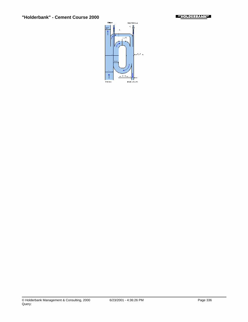
"Holderbank" - Cement Course 2000
© Holderbank Management & Consulting, 2000 6/23/2001 - 4:36:26 PM Page 336Query:

"Holderbank" - Cement Course 2000
© Holderbank Management & Consulting, 2000 6/23/2001 - 4:36:27 PM Page 337Query:
Process Technology / B05 - PT II / C09 - Heat Balance
C09 - Heat Balance

"Holderbank" - Cement Course 2000
© Holderbank Management & Consulting, 2000 6/23/2001 - 4:36:27 PM Page 338Query:
Process Technology / B05 - PT II / C09 - Heat Balance / Heat Balances of Kilns and Coolers and Related Topics
Heat Balances of Kilns and Coolers and Related TopicsTh. Richner / A. ObristPT 99/14496/E (update of VA 8/5180/E)
1. INTRODUCTION
2. OVERVIEW OF COMPLETE HEAT BALANCE PROCEDURE
2.1 Why to do a Heat Balance?
2.2 How to Proceed
3. BASIS OF BALANCE AND REMARKS REGARDING EXECUTION
3.1 Balance Limits
3.2 Guidelines for Test Duration
3.3 Kiln Operation
3.4 Kiln Data
4. HEAT BALANCE CALCULATIONS
4.1 General Remarks
4.2 Determination of Clinker Production
4.3 Heat from Fuel
4.4 Burnable Components in Raw Material
4.5 Loss due to Incomplete Combustion
4.6 Heat of Formation
4.7 Heat due to Partly Decarbonized Material
4.8 Heat of Evaporation
4.9 Sensible Heat
4.10 Heat Loss due to Radiation and Convection
5. HEAT BALANCES
5.1 General
5.2 Examples of Heat Balances of Various Kiln Systems
6. SPECIAL PART
6.1 Influence of Reference Temperature
6.2 Heat of Formation
6.3 Radiation Heat Transfer

"Holderbank" - Cement Course 2000
© Holderbank Management & Consulting, 2000 6/23/2001 - 4:36:27 PM Page 339Query:
6.4 Convective Heat Transfer
6.5 Effect of Thermal Improvements
6.6 Heat Transfer in Preheaters and Coolers and Improvement Potential
7. TEST QUESTIONS
8. LITERATURE
9. SYMBOLS AND UNITS
"Holderbank" - Cement Course 2000
© Holderbank Management & Consulting, 2000 6/23/2001 - 4:36:28 PM Page 340Query:
SUMMARY
A heat balance is an efficient tool to measure the actual state of a kiln system. It allows a betterassessment of the heat consumption and reveals the potentials for improvements (regarding thethermal aspects).
The principle of a heat balance is rather simple: we select our system limits for the balance andmeasure all inputs and outputs.
After the necessary measuring campaign we need to calculate the various heat items, e.g.:
♦ Heat of fuel combustion
♦ Combustibles in raw meal or exhaust gas
♦ Heat of formation
♦ Heat of evaporation
♦ Sensible heats of all gas and mass flows
♦ Radiation and convection heat
The heat balance shows clearly how the heat is spent among the individual items. This information istherefore most suitable to detect abnormal operating conditions or potential for improvements. As anext step we can decide which practical measures should be taken in order to achieve improvements inthe thermal energy consumption.
When improvements are realized we can often take into account that the saving of fuel is by a factor of1.3 to 1.5 higher than the primary improvements on the balance item (multiplication factor), as long aswe consider the high temperature zone.
Considerable improvements can be realized by reducing shell losses, false air inleaks, heat exchangein certain preheater types and in clinker coolers.
Process Technology / B05 - PT II / C09 - Heat Balance / Heat Balances of Kilns and Coolers and Related Topics / 1. INTRODUCTION
1. INTRODUCTION
Heat balances on a kiln system can offer extremely useful information on the thermal performance ofthe system. Heat balances show where or how the fuel heat is consumed, based on the simpleprinciple of:
input = output
Unnecessary energy losses can be easily detected.
The principle aim of this chapter is to serve a practical guide for doing heat balances on cement kilns.It can be used as working paper and does neither require special thermodynamic knowledge norsupplementary literature or tables.
For the more interested reader some special aspects are treated in a separate chapter.
The principle of heat balance may be easily transferred to other systems such as preheaters, coolersand drying systems. Therefore the use of this chapter can be extended to other systems than cementkilns.
In this chapter, only SI units are used, which means that heat is always given in kJ (kilo Joule).Conversion calculations within the chapter will no more be required. Incidentally this may also

"Holderbank" - Cement Course 2000
© Holderbank Management & Consulting, 2000 6/23/2001 - 4:36:28 PM Page 341Query:
contribute to the consequent use of SI units.
Process Technology / B05 - PT II / C09 - Heat Balance / Heat Balances of Kilns and Coolers and Related Topics / 2. OVERVIEW OFCOMPLETE HEAT BALANCE PROCEDURE
2. OVERVIEW OF COMPLETE HEAT BALANCE PROCEDURE
Process Technology / B05 - PT II / C09 - Heat Balance / Heat Balances of Kilns and Coolers and Related Topics / 2. OVERVIEW OFCOMPLETE HEAT BALANCE PROCEDURE / 2.1 Why to do a Heat Balance?
2.1 Why to do a Heat Balance?
Various reasons or circumstances may cause a need for a heat balance measurement. The followingsituations may justify a heat balance:
♦ Performance test
♦ Recording of kiln performance before/after a modification
♦ Unusually high heat consumption or abnormal kiln operational data
♦ Kiln optimization campaign
It may be self explaining that an extensive heat balance also costs money, especially if a large numberof people are involved. Therefore the costs may be put in relation to the obtainable benefits. A potentialimprovement of say 100 kJ/kg of heat consumption on a 3000 t/d kiln means a savings in the order ofUS$ 200’000 per year (at current fuel prices). In such a case it may be worthwhile to invest somemoney for a detailed investigation including a complete heat balance.
Although the specific heat consumption proper could also be determined by measuring nothing but fuelheat and clinker production, a complete heat balance does offer considerably more information andsecurity. The consistency of the measured data is proved much better, and the balance shows clearlywhere the heat is consumed. A heat balance is obviously a very efficient tool for assessment of thermalefficiency.
Process Technology / B05 - PT II / C09 - Heat Balance / Heat Balances of Kilns and Coolers and Related Topics / 2. OVERVIEW OFCOMPLETE HEAT BALANCE PROCEDURE / 2.2 How to Proceed
2.2 How to Proceed
A heat balance does not only mean calculation of heat balance items. The complete procedure usuallyincludes the following steps:
Process Technology / B05 - PT II / C09 - Heat Balance / Heat Balances of Kilns and Coolers and Related Topics / 2. OVERVIEW OFCOMPLETE HEAT BALANCE PROCEDURE / 2.2 How to Proceed / 2.2.1 1st Step: Preparation
2.2.1 1st Step: Preparation
The extent of works to be done depends on the completeness and reliability which is desired. A carefulplanning and preparation is recommendable. The following basic items must be clarified:
♦ What has to be measured (kind and location of measuring / sampling points)?
♦ Duration of test?
♦ Frequency of measurements (continuous recording, spot measurements, time intervals, etc.)?
Under above preconditions the number of people required and the necessary measuring equipmentcan be determined. Temporary equipment may usually become necessary, whereas the existing

"Holderbank" - Cement Course 2000
© Holderbank Management & Consulting, 2000 6/23/2001 - 4:36:28 PM Page 342Query:
permanent instrumentation should be carefully checked and calibrated.
The following list may be used as checklist for a test preparation:
♦ People available for test period?
♦ Does everybody know what to do at what time?
♦ Necessary logsheets for manual recordings ready?
♦ Data recording system (electronic, pen recorder, etc.) available?
♦ Flow of information among test team?
♦ Calibration or checks of instruments and scales done (flowmeters, orifice plates, venturis, dp-cells,thermocouples, etc.)?
♦ Temporary measuring equipment available? Complete? Correct span? Functionning properly?For example:
• pitot tube
• U-tube manometer / electronic manometer
• mobile thermometer
• radiation pyrometer
• gas analyzer / Orsat
• sampling equipment for gas
♦ Sampling procedure for solids (e.g. meal, dust, clinker) clarified?
♦ Analyzing facilities?
Process Technology / B05 - PT II / C09 - Heat Balance / Heat Balances of Kilns and Coolers and Related Topics / 2. OVERVIEW OFCOMPLETE HEAT BALANCE PROCEDURE / 2.2 How to Proceed / 2.2.2 2nd Step: Execution
2.2.2 2nd Step: Execution
An important precondition for a good test is a steady kiln operation. The test should only be started ifthe system has reached a constant equilibrium state. During the test, variations of operatingparameters should be avoided.
For the measuring techniques reference is made to the corresponding chapter.
It is recommended to check completeness and reliability of measurements already during the test,afterwards missing or uncertain information may create problems at the final evaluation.
Process Technology / B05 - PT II / C09 - Heat Balance / Heat Balances of Kilns and Coolers and Related Topics / 2. OVERVIEW OFCOMPLETE HEAT BALANCE PROCEDURE / 2.2 How to Proceed / 2.2.3 3rd Step: Evaluation
2.2.3 3rd Step: Evaluation
This step is the main scope of this chapter. Evaluation of data means to establish a heat balancecalculation according to the principle
“input = output“.
Process Technology / B05 - PT II / C09 - Heat Balance / Heat Balances of Kilns and Coolers and Related Topics / 2. OVERVIEW OFCOMPLETE HEAT BALANCE PROCEDURE / 2.2 How to Proceed / 2.2.4 4th Step: Discussion
2.2.4 4th Step: Discussion

"Holderbank" - Cement Course 2000
© Holderbank Management & Consulting, 2000 6/23/2001 - 4:36:29 PM Page 343Query:
A heat balance as such must bring some practical conclusions otherwise it would be only ofacademical interest. The following items may be considered:
♦ Acceptable (normal) heat consumption?
♦ Are heat balance items normal for given kiln systems?
♦ Measures in order to improve heat economy of the system?
The last item can become quite an extensive work and the economical feasibility must be consideredas well. Such subjects, however, are beyond the scope of this chapter.
Note: Summarizing, it is obvious that the 3rd step „Evaluation“ is only a limited part in the wholecontext.
Process Technology / B05 - PT II / C09 - Heat Balance / Heat Balances of Kilns and Coolers and Related Topics / 3. BASIS OFBALANCE AND REMARKS REGARDING EXECUTION
3. BASIS OF BALANCE AND REMARKS REGARDING EXECUTION
Process Technology / B05 - PT II / C09 - Heat Balance / Heat Balances of Kilns and Coolers and Related Topics / 3. BASIS OFBALANCE AND REMARKS REGARDING EXECUTION / 3.1 Balance Limits
3.1 Balance Limits
In many balance reports the boundary for the balance is not shown expressively. As long as „standardcases“ are considered it may sometimes seem evident how the balance limits were selected.Nevertheless it is advantageous to indicate always clearly where the boundary for the balance is. Thiswill avoid misunderstandings and reduce error possibilities. For that purpose a (simplified) flowsheet isrequired. In this scheme the boundary must be marked by a line which envelopes the system underconsideration. When a measuring campaign in a plant is planned such definitions should be madealready in the planning phase, i.e before the test.
Fig. 1 Examples of Balance Boundaries
The boundary generates various cutpoints with ingoing or outgoing solid- and gas streams. Likewiseradiation and convection heat crosses the boundary.
Each cutpoint means a certain item in the heat balance because it represents a heat flow either into or
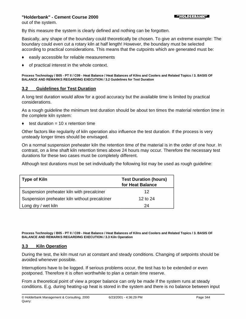
"Holderbank" - Cement Course 2000
© Holderbank Management & Consulting, 2000 6/23/2001 - 4:36:29 PM Page 344Query:
out of the system.
By this measure the system is clearly defined and nothing can be forgotten.
Basically, any shape of the boundary could theoretically be chosen. To give an extreme example: Theboundary could even cut a rotary kiln at half length! However, the boundary must be selectedaccording to practical considerations. This means that the cutpoints which are generated must be:
♦ easily accessible for reliable measurements
♦ of practical interest in the whole context.
Process Technology / B05 - PT II / C09 - Heat Balance / Heat Balances of Kilns and Coolers and Related Topics / 3. BASIS OFBALANCE AND REMARKS REGARDING EXECUTION / 3.2 Guidelines for Test Duration
3.2 Guidelines for Test Duration
A long test duration would allow for a good accuracy but the available time is limited by practicalconsiderations.
As a rough guideline the minimum test duration should be about ten times the material retention time inthe complete kiln system:
♦ test duration = 10 x retention time
Other factors like regularity of kiln operation also influence the test duration. If the process is veryunsteady longer times should be envisaged.
On a normal suspension preheater kiln the retention time of the material is in the order of one hour. Incontrast, on a lime shaft kiln retention times above 24 hours may occur. Therefore the necessary testdurations for these two cases must be completely different.
Although test durations must be set individually the following list may be used as rough guideline:
Type of Kiln Test Duration (hours)for Heat Balance
Suspension preheater kiln with precalciner 12
Suspension preheater kiln without precalciner 12 to 24
Long dry / wet kiln 24
Process Technology / B05 - PT II / C09 - Heat Balance / Heat Balances of Kilns and Coolers and Related Topics / 3. BASIS OFBALANCE AND REMARKS REGARDING EXECUTION / 3.3 Kiln Operation
3.3 Kiln Operation
During the test, the kiln must run at constant and steady conditions. Changing of setpoints should beavoided whenever possible.
Interruptions have to be logged. If serious problems occur, the test has to be extended or evenpostponed. Therefore it is often worthwhile to plan a certain time reserve.
From a theoretical point of view a proper balance can only be made if the system runs at steadyconditions. E.g. during heating-up heat is stored in the system and there is no balance between input

"Holderbank" - Cement Course 2000
© Holderbank Management & Consulting, 2000 6/23/2001 - 4:36:29 PM Page 345Query:
and output (input > output).
Process Technology / B05 - PT II / C09 - Heat Balance / Heat Balances of Kilns and Coolers and Related Topics / 3. BASIS OFBALANCE AND REMARKS REGARDING EXECUTION / 3.4 Kiln Data
3.4 Kiln Data
In order to facilitate the final discussion it is usually necessary to collect the main data of the systemsuch as:
a) System∗ process∗ type of kiln∗ nominal capacity∗ type of preheater / precalciner∗ type of cooler∗ supplier∗ year of commissioning∗ fuel and firing system∗ type of burner nozzle∗ dust reintroduction system∗ dimensions of main equipment (sizes, inclinations, etc.)∗ data on fans, derives, etc.
b) Operation∗ various operating data (rpm, kW, temperature and pressure profiles along kiln system, grate
speed, undergrate pressures, etc.)∗ electric power readings (before / after test)∗ chemical analysis of raw meal, dust(s) and clinker, LSF, SR, AR, etc.
Above data are not necessarily required for heat balance calculations proper, but they should beincluded in a complete balance report in order to describe the system and to give more information onits performance.
Process Technology / B05 - PT II / C09 - Heat Balance / Heat Balances of Kilns and Coolers and Related Topics / 4. HEAT BALANCECALCULATIONS
4. HEAT BALANCE CALCULATIONS
Process Technology / B05 - PT II / C09 - Heat Balance / Heat Balances of Kilns and Coolers and Related Topics / 4. HEAT BALANCECALCULATIONS / 4.1 General Remarks
4.1 General Remarks
Process Technology / B05 - PT II / C09 - Heat Balance / Heat Balances of Kilns and Coolers and Related Topics / 4. HEAT BALANCECALCULATIONS / 4.1 General Remarks / 4.1.1 Symbols and Units
4.1.1 Symbols and Units
A m2 area
CR W/m2K4 radiation constant
cP kJ/kg C specific heat (at const. pressure),

"Holderbank" - Cement Course 2000
© Holderbank Management & Consulting, 2000 6/23/2001 - 4:36:30 PM Page 346Query:
cP
or kJ/Nm3 C specific heat capacity
CV kJ/kg calorific value
D m diameter
g m/s2 gravity constant
h kJ/kg heat content (specific)
or kJ/Nm3
or kJ/kg cli
L m length
m kg mass
or kg/kg specific mass
mf kg/h mass flow
Qf kW heat flow (1 kW = 1 kJ/s)
t C temperature (Centigrade)
T K temperature (Kelvin)
v m/s velocity
w kg/kg water content
Greek Letters
∝ W/m2K heat transfer coefficient
ε - emissivity (for radiation)
λ W/m C heat conductivity
ρ kg/m3 density
Dimensionless Numbers
Nu Nusselt number (for heat transfer)
Pr Prandtl number
R kiln feed (raw meal) / clinker-ratio
Re Reynolds number
Indices
conv convection
rad radiation
tot total
o ambient condition or zero condition
Conversion Factors
Length 1 inch 0.0254 m
1 ft 0.3048 m
Area 1 sq. ft 0.092903 m2

"Holderbank" - Cement Course 2000
© Holderbank Management & Consulting, 2000 6/23/2001 - 4:36:30 PM Page 347Query:
0.092903 m2
Volume, Volume Flow 1 cu.ft 0.028316 m3
1 cu.ft/min 1.699 m3/h (actual m3)
Mass 1 lb. 0.45359 kg
1 short ton(USA)
907.185 kg
Pressure 1 bar 105 N/m2
1 mmH2O-Col.
9.806 N/m2
1 atm. 1.013 bar
Energy 1 kJ 1000 J
1 MJ 1000 kJ
1 kWh 3600 kJ
1 kcal 4.187 kJ
1 BTU 1.055 kJ
Temperature Conversion C = 5/9(F - 32)
K = 273.15 + C
Heat Flow 1 kW 1000 W = 1 kJ/s
1 kcal/h 1.163 W
1 BTU/h 0.29307 W
Specific Heat 1 kcal/kg C 4.187 kJ/kg C = 4187 J/kg C
1 BTU/lb F 1 kcal/kg C = 4.187 kJ/kg C
Heat Transfer Coeffic. 1 kcal/m2h C 1.163 W/m2 C
1 BTU/ft2h F 5.678 W/m2C
Standard Conditions forGases
StandardConditions
0°C and 1 atm (1.013 bar)
bar1.013(bar)p
t(C)273.16273.15
mact.Nm 33 ×+
×=
Process Technology / B05 - PT II / C09 - Heat Balance / Heat Balances of Kilns and Coolers and Related Topics / 4. HEAT BALANCECALCULATIONS / 4.1 General Remarks / 4.1.2 Reference Temperature
4.1.2 Reference Temperature
We will set the usual reference temperature to 20°C i.e. the sensible heat of mass flows at 20°Cbecomes zero.
All „heats of transformation“ such as combustion, evaporation, formation are also based on 20°Creference.
Process Technology / B05 - PT II / C09 - Heat Balance / Heat Balances of Kilns and Coolers and Related Topics / 4. HEAT BALANCECALCULATIONS / 4.1 General Remarks / 4.1.3 Input / Output

"Holderbank" - Cement Course 2000
© Holderbank Management & Consulting, 2000 6/23/2001 - 4:36:31 PM Page 348Query:
4.1.3 Input / Output
Whether a heat item represents an input or output is determined by the direction of mass flow,according to:
♦ into boundary = input
♦ out of boundary = output
This is a simple and useful convention (not a natural law).
If „heats of transformation“ occur within the boundary the net heat effect is normally used as criterion:
♦ heat producing process = input
♦ heat consuming process = output
A heat producing process is e.g. the fuel combustion (exothermic).
Process Technology / B05 - PT II / C09 - Heat Balance / Heat Balances of Kilns and Coolers and Related Topics / 4. HEAT BALANCECALCULATIONS / 4.1 General Remarks / 4.1.4 Reference Quantity
4.1.4 Reference Quantity
The heat balance is referred to 1 kg of clinker produced. This requires a general calculation step(division by clinker production) which is not shown in the following formulas in order to maintain a moresimple presentation.
Process Technology / B05 - PT II / C09 - Heat Balance / Heat Balances of Kilns and Coolers and Related Topics / 4. HEAT BALANCECALCULATIONS / 4.2 Determination of Clinker Production
4.2 Determination of Clinker Production
Process Technology / B05 - PT II / C09 - Heat Balance / Heat Balances of Kilns and Coolers and Related Topics / 4. HEAT BALANCECALCULATIONS / 4.2 Determination of Clinker Production / 4.2.1 General
4.2.1 General
The clinker production during a test is a key figure for all the following calculations. We will refer allflows and heats to 1 kg of clinker produced.
Determination of clinker production can be made by direct weighing of the production which is by farthe best method. If this can be done the following chapter 4.2.2 can be ignored. But in some cases nodirect measurement is possible. Therefore, an indirect determination may be necessary as shown inthe following.
Process Technology / B05 - PT II / C09 - Heat Balance / Heat Balances of Kilns and Coolers and Related Topics / 4. HEAT BALANCECALCULATIONS / 4.2 Determination of Clinker Production / 4.2.2 Indirect Determination
4.2.2 Indirect Determination
It is well known, that from approx. 1.56 kg raw material (not kiln feed!) 1 kg clinker can be produced.Starting from this fact it seems to be easily possible to calculate the clinker production. However, theabove factor of 1.56 if of limited practical help because it can be superimposed by dust return anddepends on some other influences.
The best method in such a case is to establish a mass balance for the system. Similar to a heat
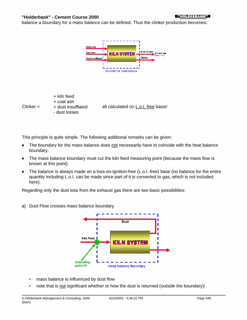
"Holderbank" - Cement Course 2000
© Holderbank Management & Consulting, 2000 6/23/2001 - 4:36:31 PM Page 349Query:
balance a boundary for a mass balance can be defined. Thus the clinker production becomes:
Clinker =
+ kiln feed+ coal ash+ dust insufflated- dust losses
all calculated on L.o.I. free basis!
This principle is quite simple. The following additional remarks can be given:
♦ The boundary for the mass balance does not necessarily have to coincide with the heat balanceboundary.
♦ The mass balance boundary must cut the kiln feed measuring point (because the mass flow isknown at this point).
♦ The balance is always made on a loss-on-ignition-free (L.o.I.-free) base (no balance for the entirequantity including L.o.I. can be made since part of it is converted to gas, which is not includedhere).
Regarding only the dust loss from the exhaust gas there are two basic possibilities:
a) Dust Flow crosses mass balance boundary
• mass balance is influenced by dust flow
• note that is not significant whether or how the dust is returned (outside the boundary)!

"Holderbank" - Cement Course 2000
© Holderbank Management & Consulting, 2000 6/23/2001 - 4:36:32 PM Page 350Query:
•
b) Dust flow does not leave mass balance boundary (internal dust return)
• mass balance is not influenced by dust flow
• internal dust return must be steady, i.e. no storage being built up (silos!)
•
Two practical examples illustrating above two cases are shown in the following.
Process Technology / B05 - PT II / C09 - Heat Balance / Heat Balances of Kilns and Coolers and Related Topics / 4. HEAT BALANCECALCULATIONS / 4.2 Determination of Clinker Production / 4.2.3 Examples
4.2.3 Examples
a) External Dust Recirculation (outside of boundary)
Fig. 2 Mass Balance / External Dust Recirculation
mf (dry)[t/h]
L.o.I.[-]
mf (1-L.o.I.)[t/h]
Kiln Feed (KF) 204.0 0.357 131.17
Coal Ash (Ash) 1.8 ∼ 0 + 1.80
Dust in Exhaust (D) 11.0 0.315 - 7.54
Bypass Dust (BpD) 2.1 0.070 - 1.95
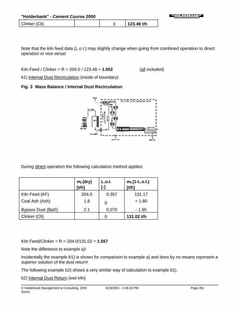
"Holderbank" - Cement Course 2000
© Holderbank Management & Consulting, 2000 6/23/2001 - 4:36:32 PM Page 351Query:
Bypass Dust (BpD) 2.1 0.070 - 1.95
Clinker (Cli) ∼ 0 123.48 t/h
Note that the kiln feed data (L.o.I.) may slightly change when going from combined operation to directoperation or vice versa!
Kiln Feed / Clinker = R = 204.0 / 123.48 = 1.652 (all included)
b1) Internal Dust Recirculation (inside of boundary)
Fig. 3 Mass Balance / Internal Dust Recirculation
During direct operation the following calculation method applies:
mf (dry)[t/h]
L.o.I.[-]
mf (1-L.o.I.)[t/h]
Kiln Feed (KF) 204.0 0.357 131.17
Coal Ash (Ash) 1.8 ∼ 0 + 1.80
Bypass Dust (BpD) 2.1 0.070 - 1.95
Clinker (Cli) ∼ 0 131.02 t/h
Kiln Feed/Clinker = R = 204.0/131.02 = 1.557
Note the difference to example a)!
Incidentally the example b1) is shown for comparison to example a) and does by no means represent asuperior solution of the dust return!
The following example b2) shows a very similar way of calculation to example b1).
b2) Internal Dust Return (wet kiln)

"Holderbank" - Cement Course 2000
© Holderbank Management & Consulting, 2000 6/23/2001 - 4:36:33 PM Page 352Query:
Fig. 4 Mass Balance / Internal Dust Recirculation
mf (wet) [t/h]
mf (dry)[t/h]
L.o.I.[-]
mf (1-L.o.I.)[t/h]
Kiln Feed (KF) 42 26.46 0.360 16.93
Coal Ash (Ash) - 0.8 ∼ 0 0.8
Clinker ∼ 0 17.73 t/h
Process Technology / B05 - PT II / C09 - Heat Balance / Heat Balances of Kilns and Coolers and Related Topics / 4. HEAT BALANCECALCULATIONS / 4.3 Heat from Fuel
4.3 Heat from Fuel
Process Technology / B05 - PT II / C09 - Heat Balance / Heat Balances of Kilns and Coolers and Related Topics / 4. HEAT BALANCECALCULATIONS / 4.3 Heat from Fuel / 4.3.1 Fuel Firing
4.3.1 Fuel Firing
Fuel can be introduced at the following locations:
♦ Kiln firing
♦ Secondary firing or precalciner
♦ Burnable components in raw meal
Generally the heat from fuel is calculated:
h = m · CV (kJ/kg cli)
h = heat (kJ/kg cli)
m = specific fuel consumption (kg/kg cli or Nm3/kg cli)
CV = calorific value (kJ/kg fuel or kJ/Nm3 fuel)
For the calorific value CV only the low (or net) value is used within the „Holderbank“ Group (for

"Holderbank" - Cement Course 2000
© Holderbank Management & Consulting, 2000 6/23/2001 - 4:36:33 PM Page 353Query:
conversion see chapter „Combustion Engineering“).
Heat balance referring to high (or gross) heat value are sometimes encountered. But here an importantnote must be made: the use of high heat values is based on a quite different method of consideringheat losses. Therefore those balances cannot be compared directly to our type of balance.
Process Technology / B05 - PT II / C09 - Heat Balance / Heat Balances of Kilns and Coolers and Related Topics / 4. HEAT BALANCECALCULATIONS / 4.3 Heat from Fuel / 4.3.2 Coal Firing
4.3.2 Coal Firing
For coal firing it is essential that the CV and the consumption (m) refer both to the same conditions.The normal convention is to refer to the state as fed to the kiln burner.
The state as fed to burner may sometimes be different from the state as analyzed. Differences canoccur because of dust addition in coal mill, loss of volatile matter or just simply by changed moistureconditions.
If the actual CV at the given coal moisture w is not known it can be calculated from the value CVo atthe moisture wo:
CV = [(1-w) / (1-w0)] · (CV0 + w0 ·r) - w ·r
where: r = 2450 kJ/kg
= heat of water evaporation at reference temperature 20°C
w, wo = weight fractions of water
Examples:
a) Coal, CV at 5% moisture = 26’500 kJ/kgCV at 1% moisture (as fed to burner) = ?
CV = [(1-0.01) / (1-0.05)] · (26500 + 0.05·2450) - 0.01·2.450
CV = 27’464 kJ/kg
If above coal (1% moisture) is fired at a specific rate of 0.1230 kg/kg cli:
h = 0.1230 · 27’464 = 3’378 kJ/kg cli
b) If the CV for dry matter is known (CVdry) the general formula can be simplified (for wo = 0):
CV = (1 - w) CVdry - w · r
CVdry = 28 MJ/kg, moisture 2%
CV = 28 · (1 - 0.02) - 0.02 · 2.45 = 27.39 MJ/kg
Process Technology / B05 - PT II / C09 - Heat Balance / Heat Balances of Kilns and Coolers and Related Topics / 4. HEAT BALANCECALCULATIONS / 4.4 Burnable Components in Raw Material
4.4 Burnable Components in Raw Material
"Holderbank" - Cement Course 2000
© Holderbank Management & Consulting, 2000 6/23/2001 - 4:36:34 PM Page 354Query:
Process Technology / B05 - PT II / C09 - Heat Balance / Heat Balances of Kilns and Coolers and Related Topics / 4. HEAT BALANCECALCULATIONS / 4.4 Burnable Components in Raw Material / 4.4.1 Organic Matter
4.4.1 Organic Matter
Organic matter can be present in the raw meal e.g. in form of oil shale or exceptionally even in form offree crude oil.
Such material is partly volatilized in the preheating zone and leaves the system partly as unburnt lighthydrocarbons. If the latter are actually measured and considered in the total heat balance it isrecommended to determine the calorific value of the raw meal (not directly, but by extracting its organicmatter). Thus the heat input becomes:
h = CVlow · R (kJ/kg cli)
where: CVlow = calorific value due to organic matter, referred to 1 kg raw meal
R = kiln feed / clinker - factor
If light hydrocarbons in the exhaust gas are not measured nor considered in the total heat balanceanyway the following approach will produce better results:
Determine the organic content only (org. C, measured by burning in pure O2 to CO2). Then considerexclusively the organic C (the rest can be neglected). The approximate heat input becomes:
h = C · R · 33’000 kJ/kg (kJ/kg cli)
where C = organic carbon content in raw meal
Above mentioned is only an approximation but often used due to its simplicity.
Example:
R = 1.6 kg/kg cli, C = 0.2% carbon
q = 0.002 · 1.6 · 33’000 = 106 kJ/kg cli
Process Technology / B05 - PT II / C09 - Heat Balance / Heat Balances of Kilns and Coolers and Related Topics / 4. HEAT BALANCECALCULATIONS / 4.4 Burnable Components in Raw Material / 4.4.2 Inorganic Matter
4.4.2 Inorganic Matter
In certain cases residues of non-oxidized pyrite (FeS2) can occur in the raw meal. The heat inputbecomes:
h = S · R · 12’930 kJ/kg (kJ/kg cli)
where S = weight fraction of sulfur (expressed as S!) from pyrite in raw meal
Example:
R = 1.6 kg/kg cli, 0.05% S (from pyrite) in raw meal
h = 0.0005 · 1.6 · 12’930 = 10 kJ/kg cli

"Holderbank" - Cement Course 2000
© Holderbank Management & Consulting, 2000 6/23/2001 - 4:36:34 PM Page 355Query:
The practical heat effect in the above case is only marginal.
Process Technology / B05 - PT II / C09 - Heat Balance / Heat Balances of Kilns and Coolers and Related Topics / 4. HEAT BALANCECALCULATIONS / 4.5 Loss due to Incomplete Combustion
4.5 Loss due to Incomplete Combustion
If unburnt gases such as CO, H2, CH4 occur in the exhaust gas an additional heat output occurs.
The loss can be calculated to:
h = m · (CO · 12’640 + H2 · 10’800 + CH4 · 35’840) (kJ/kg cli)
m = specific gas quantity (Nm3/kg cli)
CO, H2, CH4 = volume fractions in exhaust (referred to wet gas)
In most cases only CO is measured and then the calculation becomes:
h = m · CO · 12’640 (kJ/kg cli)
Example
m = 1.50 Nm3/kg cli (SP kiln)
CO = 0.2% (ref to wet)
q = 1.50 · 0.002 · 12’640 = 38 kJ/kg cli
Process Technology / B05 - PT II / C09 - Heat Balance / Heat Balances of Kilns and Coolers and Related Topics / 4. HEAT BALANCECALCULATIONS / 4.6 Heat of Formation
4.6 Heat of Formation
The heat of formation takes into account all main reactions which occur when raw meal is transformedto clinker, as follows:
RAW MEAL
♦ Heat of dehydration of clay (endothermic)
♦ Heat of decarbonation of CaCO3 + MgCO3 (endothermic)
♦ Heat of formation of clinker (exothermic!)
CLINKER
In most of the practical cases it is sufficient to assume a constant value of
h = 1750 kJ/kg cli
The value mentioned before represents a heat output since the overall reaction is endothermic (heatconsuming). The main contribution to the overall value comes from the decarbonation of CaCO3(approx. 2100 kJ/kg cli).
The heat of formation may naturally have some variations from one raw meal to the other. But due tothe narrow range which is specified for the cement clinker composition no major deviations (of saymore than +/- 50 kJ/kg cli) have to be expected in normal cases.
If the CaO in clinker does not originate from CaCO3, but from raw material sources containing less CO2than the CaO balance (such as coal ash or partly decarbonized raw mix) the heat of formation would
"Holderbank" - Cement Course 2000
© Holderbank Management & Consulting, 2000 6/23/2001 - 4:36:35 PM Page 356Query:
theoretically change. However, this problem can be easily avoided by the following definition:
♦ All mass flows (as kiln feed, dust losses, coal ash) which carry a certain amount of CaO not comingfrom CaCO3 are considered as „heat flows“ according to their „non-carbonatic“ CaO content (seechapter 4.7).
By following the above definition it is not necessary to make alterations at the heat of formation. An„abnormal“ situation can simply be treated by creating additional inputs or outputs, but not by changingthe „standard“ heat of formation.
The procedure is based on the idea of an „ideal“ clinker burning from pure carbonates. If those idealconditions do not apply we set corrections in the corresponding heat inputs or outputs. Such principlesare well known from calculation of bypass CaO-losses.
Additional information on the heat of formation is given in chapter 6.2.
Process Technology / B05 - PT II / C09 - Heat Balance / Heat Balances of Kilns and Coolers and Related Topics / 4. HEAT BALANCECALCULATIONS / 4.7 Heat due to Partly Decarbonized Material
4.7 Heat due to Partly Decarbonized Material
Decomposition of carbonates in an essential heat effect in a cement kiln. Usually one thinks of the twoextreme cases of either complete presence of carbonates (CaCO3, MgCO3) or complete absence ofcarbonates (e.g. clinker). But there can also be cases in between which influence the heat balance.
Material streams can transport non-sensible heat due to partly decarbonized material (CaO) ornon-carbonatic CaO. The following possibilities exist:
1) raw meal (containing e.g. CaO free or non carbonatic, CaO-bearing minerals)
2) exhaust gas dust (partly decarbonized)
3) bypass dust (largely decarbonized)
4) coal ash
The heat can either be negative or positive according to the direction of flow (ingoing or outgoing).
If item 2) (exhaust gas) is considered in the balance it is essential to consider also item 1) (raw meal)!In many cases kiln dust (which contains some free CaO) is returned to the kiln but not necessarily atexactly the same rate as the outcoming dust (e.g. on a system combined with raw mill, alternatingbetween combined and direct operation). Even if dust is returned the net heat effect of item 1) minusitem 2) may not automatically be zero!
If the CaO and CO2 is known from chemical analysis the non carbonatic part CaOnc can be calculated:
CaOnc = CaO - (56 / 44) CO2
Strictly speaking, above formula is only correct if no other carbonates than CaCO3 occur. If MgCO3 ispresent in form of carbonates the „carbonatic MgO“ has to be taken into account:
CaOnc = CaO - 56 [(CO2/44) - (MgO/40)]
Thus the heat is calculated to
h = m · CaOnc · 3150 (kJ/kg cli)
m = spec. mass (kg/kg cli)
CaOnc = „non-carbonatic“ CaO, expresses as weight fraction

"Holderbank" - Cement Course 2000
© Holderbank Management & Consulting, 2000 6/23/2001 - 4:36:35 PM Page 357Query:
Above formula does not consider the small possible influence of MgCO3 decarbonation heat. If theassumption can be made that all MgO occurs in non-carbonatic form (e.g. after a heat treatment in the700°C range) the following improved formula can be applied:
h = m (CaOnc . 3150 + MgO . 2710) (kJ/kg cli)
Examples
1) Raw Meal and Kiln Dust
(dust returned, measurements refer to balance limits, normal raw mix)
Raw Meal Kiln Dust
R = 1.65 kg/kg cli m = 0.09 kg/kg cli
CaO = 42.3% CaO = 43.5%
MgO = 0.9% MgO = 1.1%
CO2 = 34.0% CO2 = 30.5%
CaOnc = 42.3-56 [(34/44) - (0.9/40) = 0.3%
CaOnc = 43.5-56 [(30.5/44) - (1.1/40) = 6.2%
h = 1.65 · 0.003 · 3150 = 16 kJ/kg cli (input)
h = 0.09 · 0.062 · 3150 = 18 kJ/kg cli (output)
In the above example the net heat effect is virtually zero and may be completely neglected. But thismay not be used as a general rule as shown by the next example.
2) Raw Meal and Kiln Dust
(similar to example 1), but raw mix containing a major proportion of non-carbonatic CaO)
Raw Meal Kiln Dust
R = 1.60 kg/kg cli m = 0.09 kg/kg cli
CaO = 43.2% CaO = 43.5%
MgO = 0.9% MgO = 1.1%
CO2 = 30.0% CO2 = 30.5%
CaOnc = 43.2-56 [(30/44) - (0.9/40) = 6.28%
CaOnc = 43.5-56 [(30.5/44) - (1.1/40) = 6.2%
h = 1.60 · 0.0628 · 3150 = 317 kJ/kg cli (input)
h = 0.09 · 0.062 · 3150 = 18 kJ/kg cli (output)

"Holderbank" - Cement Course 2000
© Holderbank Management & Consulting, 2000 6/23/2001 - 4:36:36 PM Page 358Query:
Although non-carbonatic CaO occurs seldom, it may largely contribute to the heat balance (in the latterexample a net effect of 299 kJ/kg cli!). The practical problem, however, is to determine the CaOnc withsufficient precision.
3) Bypass Dust
m = 0.04 kg/kg cli (quantity of bypass dust)
CaO = 56.2%
MgO = 1.0%
CO2 = 1.8%
CaOnc = 56.2 - (56/44) * 1.8 = 53.9%
q = 0.04 * 0.539 * 3150 + 0.01 * 2710 = 95 kJ/kg cli
(output)
4) Coal Ash
m = 0.02 kg/kg cli (quantity of ash)
CaO = 21%
MgO = 2%
q = 0.02 (0.21 * 3150 + 0.02 * 2710) = 14 kJ/kg cli
(input)
Process Technology / B05 - PT II / C09 - Heat Balance / Heat Balances of Kilns and Coolers and Related Topics / 4. HEAT BALANCECALCULATIONS / 4.8 Heat of Evaporation
4.8 Heat of Evaporation
If water is evaporated within the balance limits the heat of evaporation becomes
h = m · 2450 (kJ/kg cli)
m = evaporated water (kg/kg cli)
Above items means an output. A large source of water evaporation is usually the slurry feed to a wetkiln.
Although the calculation of heat of evaporation is obviously simple a few notes are given:
♦ Only the free water of thekiln feed is considered (the hydrate water is already included in the heat of formation!).

"Holderbank" - Cement Course 2000
© Holderbank Management & Consulting, 2000 6/23/2001 - 4:36:36 PM Page 359Query:
♦ Water evaporation can also be caused by water injection into preheater, kiln, cooler, etc.
♦ The water evaporated from the fuel must not be included (this effect is already included in the netheat value, provided it has been determined as described in paragraph 4.3).
Examples
a) Wet Kiln: slurry water content = 35%
R = 1.56 kg/kg cli (dry)
m = 0.35 / (1-0.35) · 1.56 = 0.84 kg/kg cli
h = 0.84 · 2450 = 2058 kJ/kg cli
b) Water Spray into Planetary Cooler
m = 0.05 kg/kg cli
h = 0.05 * 2450 = 123 kJ/kg cli
Process Technology / B05 - PT II / C09 - Heat Balance / Heat Balances of Kilns and Coolers and Related Topics / 4. HEAT BALANCECALCULATIONS / 4.9 Sensible Heat
4.9 Sensible Heat
Process Technology / B05 - PT II / C09 - Heat Balance / Heat Balances of Kilns and Coolers and Related Topics / 4. HEAT BALANCECALCULATIONS / 4.9 Sensible Heat / 4.9.1 General
4.9.1 General
Generally the sensible heats are calculated as follows:
h = m · cp · (t - 20°C) (kJ/kg cli)
m = specific mass (kg/kg cli or Nm3/kg cli)
cp = average specific heat (kJ/kg C or kJ/Nm3 C)
t = temperature of m (C)
Above formula uses a reference temperature of 20°C, i.e. sensible heats of material and gas flows at20°C are zero.
The value h (kJ/kg cli) can either be positive (if t > 20°C) or negative (if t < 20°C).
Whether h represents an input or an output (see 4.1) depends only on the direction of the flow „m“:
♦ if m = entering boundary → h = input
♦ if m = leaving boundary → h = output
Basically the value m can be expressed as kg or Nm3. It is then logical that the cp values used mustalso refer to same unit (per kg or per Nm3).
For convenience we use the following convention:
♦ for solid flows → unit = kg
♦ for gaseous flows → unit = Nm3 1)
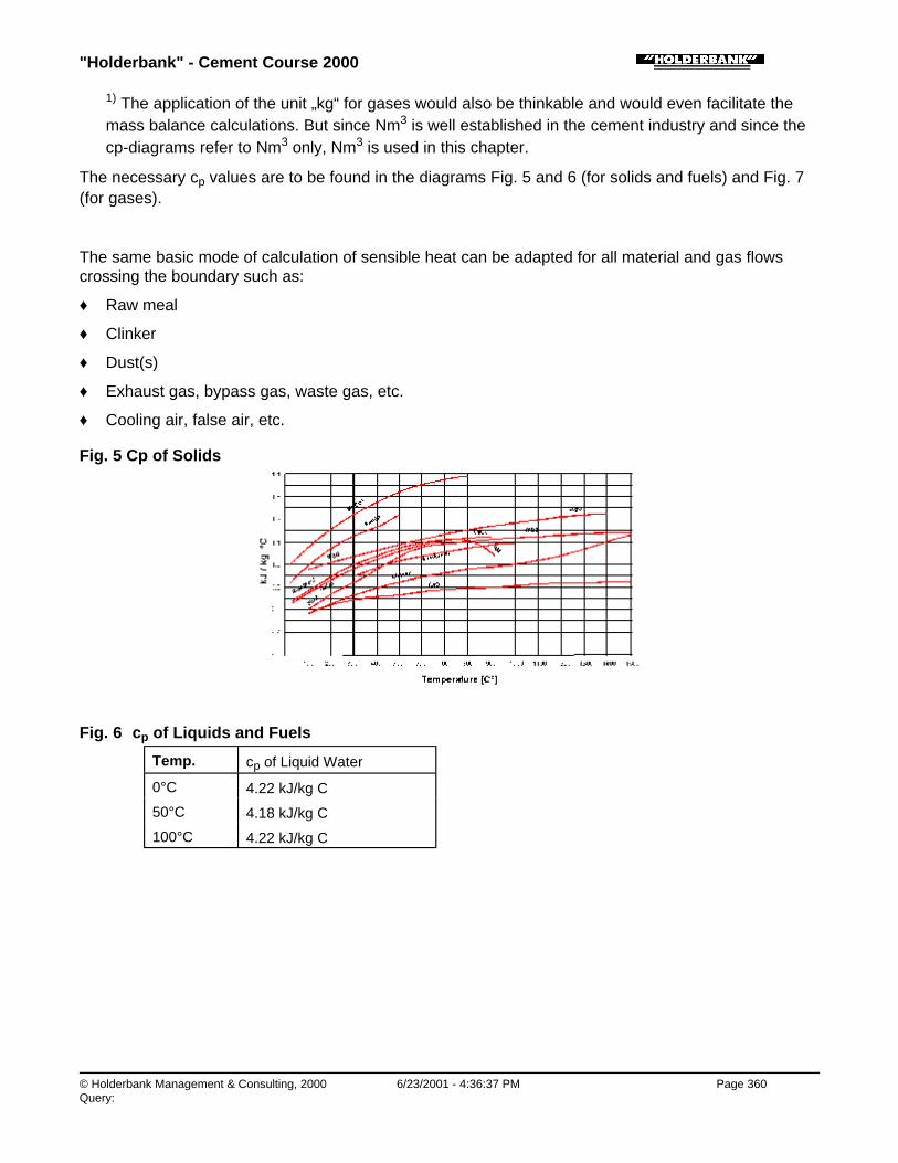
"Holderbank" - Cement Course 2000
© Holderbank Management & Consulting, 2000 6/23/2001 - 4:36:37 PM Page 360Query:
1) The application of the unit „kg“ for gases would also be thinkable and would even facilitate themass balance calculations. But since Nm3 is well established in the cement industry and since thecp-diagrams refer to Nm3 only, Nm3 is used in this chapter.
The necessary cp values are to be found in the diagrams Fig. 5 and 6 (for solids and fuels) and Fig. 7(for gases).
The same basic mode of calculation of sensible heat can be adapted for all material and gas flowscrossing the boundary such as:
♦ Raw meal
♦ Clinker
♦ Dust(s)
♦ Exhaust gas, bypass gas, waste gas, etc.
♦ Cooling air, false air, etc.
Fig. 5 Cp of Solids
Fig. 6 cp of Liquids and Fuels
Temp. cp of Liquid Water
0°C 4.22 kJ/kg C
50°C 4.18 kJ/kg C
100°C 4.22 kJ/kg C

"Holderbank" - Cement Course 2000
© Holderbank Management & Consulting, 2000 6/23/2001 - 4:36:37 PM Page 361Query:
Fig. 7 cp of Gases
Process Technology / B05 - PT II / C09 - Heat Balance / Heat Balances of Kilns and Coolers and Related Topics / 4. HEAT BALANCECALCULATIONS / 4.9 Sensible Heat / 4.9.2 Calculation of cp of Mixtures
4.9.2 Calculation of cp of Mixtures
The cp values are usually tabulated for pure substances. If a mixture is present it may becomenecessary to calculate the cp starting from the given composition. This is better shown in a practicalexample (instead of a general formula):
Example:
Exhaust gas of suspension preheater kiln at 360 °C
♦ Measured by Orsat (dry):
• CO2 = 27.2% (CO = O)
• O2 = 4.3%
• N2 = 100 - 27.2 - 4.3 = 68.5%
♦ From moisture determination:
• H2O = 0.08 Nm3/Nm3 wet
"Holderbank" - Cement Course 2000
© Holderbank Management & Consulting, 2000 6/23/2001 - 4:36:38 PM Page 362Query:
What is the cp value of the mixture (wet gas)?
Dry Gas(Vol %)
Wet Gas(Vol %)
cp (pure(kJ/Nm3C)
cp x Vol. Frac.(kJ/Nm3C)
CO2 27.2 25.0 1.92 0.480
O2 4.3 4.0 1.37 0.055
N2 68.5 63.0 1.31 0.825
H2O 0 8.0 1.55 0.124
Total 100% 100% - 1.484 ≅ 1.48
Result: cp of mixture = 1.48 kJ/Nm3C (at 360°C)
The above value is typical for a normal SP kiln. We will always find values in the 1.5 kJ/Nm3C range.
Process Technology / B05 - PT II / C09 - Heat Balance / Heat Balances of Kilns and Coolers and Related Topics / 4. HEAT BALANCECALCULATIONS / 4.10 Heat Loss due to Radiation and Convection
4.10 Heat Loss due to Radiation and Convection
Process Technology / B05 - PT II / C09 - Heat Balance / Heat Balances of Kilns and Coolers and Related Topics / 4. HEAT BALANCECALCULATIONS / 4.10 Heat Loss due to Radiation and Convection / 4.10.1 General
4.10.1 General
In practice it is quite convenient to treat both, radiation and convection heat transfer together. Althoughthe physical laws of these two heat transfer phenomenas are different they are usually given as a total.
The determination of total heat transfer coefficients by using simplified working diagrams will beaccurate enough. Therefore the theory how to calculate the values is treated in separate chapters (6.3and 6.4). The user of this chapter does usually not need to go into details of radiation and convectionheat transfer theories. In addition, the calculation from the complete theory would hardly increase thepractical accuracy, since all these theories contain a certain inaccuracy.
Process Technology / B05 - PT II / C09 - Heat Balance / Heat Balances of Kilns and Coolers and Related Topics / 4. HEAT BALANCECALCULATIONS / 4.10 Heat Loss due to Radiation and Convection / 4.10.2 Radiation Heat Transfer
4.10.2 Radiation Heat Transfer
Radiation heat transfer depends on the surface temperature and the emissivity ε (0...1).
Typical values for ε:
Type of Surface Temperature °C ε
Rough oxidized steel 100 1
Rough oxidized steel 400 0.9

"Holderbank" - Cement Course 2000
© Holderbank Management & Consulting, 2000 6/23/2001 - 4:36:38 PM Page 363Query:
Rough oxidized steel 400 0.9
White lime paint (on steel) 400 0.8
Aluminium paint 100 0.2 to 0.4
Aluminium, rolled sheet metal 100 to 500 0.08
Aluminium, polished or bright foil 100 to 500 0.04
In most cases an ε value has to be set at the pyrometer used for the measurement (depending on thetype).
For pyrometers giving readings for a constant emissivity ε = 1. Fig. 8 can be used for correction.
The pure radiation heat transfer coefficient ∝rad (W/m2C) is shown in Fig. 9.
Note that the temperature axis in Fig. 9 means temperature difference to ambient (same convention asfor the following Fig. 10 and 11 - see paragraph 4.10.3 and 4.10.4).
Radiation heat transfer calculation does usually not create special problems as long as the radiatingsurfaces face freely towards ambient. A particular situation occurs on a planetary cooler where certaindirections of radiation are shielded. That means not all areas are able for radiation towards theambient.
Here, it would be obviously wrong to consider the total of the tube surfaces as radiation area. As a firstapproach the outer enveloping cylinder area (enveloping all tubes, see sketch) can be taken asreference area.
Fig. 8 Relation between Emissivity ε and True and Apparent Surface Temperature
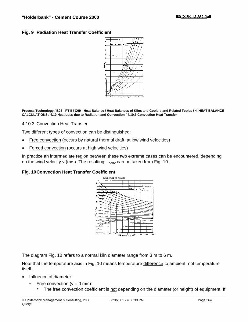
"Holderbank" - Cement Course 2000
© Holderbank Management & Consulting, 2000 6/23/2001 - 4:36:39 PM Page 364Query:
Fig. 9 Radiation Heat Transfer Coefficient
Process Technology / B05 - PT II / C09 - Heat Balance / Heat Balances of Kilns and Coolers and Related Topics / 4. HEAT BALANCECALCULATIONS / 4.10 Heat Loss due to Radiation and Convection / 4.10.3 Convection Heat Transfer
4.10.3 Convection Heat Transfer
Two different types of convection can be distinguished:
♦ Free convection (occurs by natural thermal draft, at low wind velocities)
♦ Forced convection (occurs at high wind velocities)
In practice an intermediate region between these two extreme cases can be encountered, dependingon the wind velocity v (m/s). The resulting ∝conv can be taken from Fig. 10.
Fig. 10 Convection Heat Transfer Coefficient
The diagram Fig. 10 refers to a normal kiln diameter range from 3 m to 6 m.
Note that the temperature axis in Fig. 10 means temperature difference to ambient, not temperatureitself.
♦ Influence of diameter
• Free convection (v = 0 m/s):∗ The free convection coefficient is not depending on the diameter (or height) of equipment. If

"Holderbank" - Cement Course 2000
© Holderbank Management & Consulting, 2000 6/23/2001 - 4:36:40 PM Page 365Query:
there is no wind Fig. 10 can be applied for any dimension.
• Forced convection:∗ In contrast to the free convection the forced convection does depend on the diameter. For
this reason the application range of Fig. 10 is limited to 3 m...6 m, but only if high windvelocities occur. At low wind velocities no diameter limits exist.
∗ For very small tubes (or gas ducts) the following corrections of ∝conv (increases) can bemade:For ∅ 2 m + 15% For ∅ 1 m + 30% only at high wind velocities (min. 2 m/s)For ∅ 0.5 m + 50%
Process Technology / B05 - PT II / C09 - Heat Balance / Heat Balances of Kilns and Coolers and Related Topics / 4. HEAT BALANCECALCULATIONS / 4.10 Heat Loss due to Radiation and Convection / 4.10.4 Total Heat Transfer Coefficient (Radiation andConvection)
4.10.4 Total Heat Transfer Coefficient (Radiation and Convection)
For the determination of the total heat transfer coefficient ∝tot (W/m2C) two cases are possible:
a) Standard Case
ε = 0.9 (rough oxidized steel surface)
This particular case is rather simple. Direct use of Fig. 11 is possible.
(Go into diagram with temperature difference and read out the total heat transfer coefficient.)
b) Non-standard Case
ε differs clearly from 0.9 and/or correction of convective heat transfer coefficient is necessary.
Make use of Fig. 9 and 10.
∝tot = ∝rad + ∝conv
(Caution: never add free convection + forced convection, Fig. 10 does already include the overlappingof both effects.)
Fig. 11 Radiation and Convection Heat Transfer Coefficient (total)

"Holderbank" - Cement Course 2000
© Holderbank Management & Consulting, 2000 6/23/2001 - 4:36:40 PM Page 366Query:
Process Technology / B05 - PT II / C09 - Heat Balance / Heat Balances of Kilns and Coolers and Related Topics / 4. HEAT BALANCECALCULATIONS / 4.10 Heat Loss due to Radiation and Convection / 4.10.5 Total Heat Flow
4.10.5 Total Heat Flow
The total heat flow from radiation and convection heat transfer is calculated according to:
Qf = αtot · A · (t - t0) (W)
Qf = heat flow (W); 1kW = 1000W
αtot = αrad + αconv = total heat transfer coefficient (W/m2C)
A = shell area (m2)
t = shell temperature (C)
t0 = ambient temperature (C)
From the heat flow Qf the specific loss can be calculated:
h = Qf (kW) / mf (t/h) · 3.6 (kJ/kg cli)
mf = clinker production (t/h)
3.6 = conversion factor, because of unit (t/h) for mf
If the temperature of a shell area is not approximately constant it is necessary to subdivide the areainto individual sections.
On a rotary kiln we may e.g. select about 10 (or more) individual cylindrical areas, each of them havingthe surface:
Ai = Π · Di · Li (m2)
Example:
♦ Rotary kiln
♦ Clinker production = 1900 t/d = 79.17 t/h
♦ ∅ 4.4 m x 67 m
♦ Average emissivity: ε = 0.9
♦ Ambient temperature = 20°C
♦ Average wind velocity v = 1 m/s (nearly free convection!)
♦ Shell temperature profile as indicated in the following table:
LengthPosition(m)
ElementLength(m)
Dia-meter
(m)
ElementArea 1)
(m2)
SurfaceTemp.(°C)
ε
(-)
∝total2)
(W/m2C)
Qf (heat flow)(W)
0 - 5 5 4.40 69.1 230 0.9 22.7 331’000
5 - 10 5 4.40 69.1 360 0.9 32.9 774’000

"Holderbank" - Cement Course 2000
© Holderbank Management & Consulting, 2000 6/23/2001 - 4:36:41 PM Page 367Query:
5 - 10 5 4.40 69.1 360 0.9 32.9 774’000
10 - 15 5 4.40 69.1 310 0.9 28.6 574’000
15 - 25 10 4.40 138.2 220 0.9 22.1 611’000
25 - 35 10 4.40 138.2 330 0.9 30.3 1’299’000
35 - 45 10 4.40 138.2 260 0.9 24.9 825’000
45 - 55 10 4.40 138.2 290 0.9 27.1 1’011’000
55 - 60 5 4.40 69.1 270 0.9 25.6 442’000
60 - 67 7 4.40 96.8 220 0.9 22.1 428’000
Total 67 m 926.1 m2 6’295’000 W
Total heat loss = 6’295 kW
Specific heat loss = ht /17.796.3295'6 ⋅
= 286 kJ/kg cli
1) A = ∏ . D . L (cylinder)
2) radiation plus convection (see Fig. 11)
Process Technology / B05 - PT II / C09 - Heat Balance / Heat Balances of Kilns and Coolers and Related Topics / 5. HEAT BALANCES
5. HEAT BALANCES
Process Technology / B05 - PT II / C09 - Heat Balance / Heat Balances of Kilns and Coolers and Related Topics / 5. HEAT BALANCES/ 5.1 General
5.1 General
The results for heat inputs and outputs as calculated according to the preceding paragraph 4 aresummarized in a balance sheet.
Table 1 (complete kiln system) and Table 2 (cooler only) are given as examples. They may also beused as checklist for completeness of own measurements and calculations.
♦ „Rest“-item:
• A real balance (from complete date) will always include an item „rest“, where all measuringerrors (no measurement is 100% accurate) and non-considered items are included. Theamount of the „rest“ item should not exceed 3% of the total heat input.
♦ Heat consumption:
• The actual heat consumption is the total of fuel input(s) which is not exactly the same as thetotal of heat inputs. If there are more than one fuel input, it is advantageous to indicate theactual (true) heat consumption separately.
♦ Cooler balance:
• On a cooler, reliable measurement of secondary air heat is virtually impossible. Therefore, thisvalue is determined by balance calculation and no rest item is given. The thermal efficiency ofthe cooler is usually defined as:η = heat of secondary (and tertiary) air (%) heat of hot clinker

"Holderbank" - Cement Course 2000
© Holderbank Management & Consulting, 2000 6/23/2001 - 4:36:41 PM Page 368Query:
• The % values in the balance sheet, however, are based on the total of inputs. This can cause aslight difference from the percentage of above η.
Table 1 Heat Balance of Cement Kiln System
(General case)
- All referred to 1 kg clinker
- Reference temperature = 20°C
- Ambient temperature = ...... °C
- Production = ...... t/h
- Specific heat cons. = ...... kJ/kg cli
Specifications Temp. Heat
(kg/kg cli),(Nm3/kg cli)(kW) etc.
(°C) (kJ/kgcli)
(%)
INPUTFuel combustion - primary firing - secondary firing
--
Burnable matter in kiln feed -
Raw meal: sensible heat
Fuel: sensible heat
Primary air: sensible heat
Cooler air: sensible heat
CaO (non-carbonatic) in kiln feed -
Total of inputs - 100%
OUTPUT
Heat of formation - -
Water evaporation: - kiln feed - water spray(s)
--
Exhaust gas: - sensible heat - dust CaO-loss - unburnt gases (CO, etc.)
--
Cooler: - waste air sensible heat - middle air sensible heat - clinker exit sensible heat
Bypass losses: - sensible heat - dust sensible heat - dust CaO-loss - unburnt gases (CO, etc.)
--

"Holderbank" - Cement Course 2000
© Holderbank Management & Consulting, 2000 6/23/2001 - 4:36:42 PM Page 369Query:
- unburnt gases (CO, etc.) -
Radiation and Convection: - preheater - rotary kiln - cooler - tert. Air duct
kWkWkWkWkW
Rest
Total of outputs - 100%
Table 2 Heat Balance of Clinker Grate Cooler
All referred to 1 kg clinker
Reference temperature = 20°C
Ambient temperature = ... °C
Specifications Temp. Heat
(°C) (kJ/kgcli)
(%)
INPUT
Hot clinker
Cooling air
Total input 100%
OUTPUT
Secondary air (incl. dust)
Tertiary air
Middle air
Waste air
Clinker outlet
Water spray
Radiation and convection
Total output 100%
Process Technology / B05 - PT II / C09 - Heat Balance / Heat Balances of Kilns and Coolers and Related Topics / 5. HEAT BALANCES/ 5.2 Examples of Heat Balances of Various Kiln Systems
5.2 Examples of Heat Balances of Various Kiln Systems
Heat balances are given in Table 3 of various kiln systems. While comparing these it has to kept inmind, however, that kiln systems cannot only be judged based on these heat balances. The heatconsumption of kiln system may depend on many items, those of major influence are:

"Holderbank" - Cement Course 2000
© Holderbank Management & Consulting, 2000 6/23/2001 - 4:36:43 PM Page 370Query:
♦ Kiln size, i.e. production rate
♦ Heat loss due to radiation and convection
♦ Secondary air quantity and temperature
♦ Operating conditions of kiln
Furthermore related systems have also to be taken into account. Consider a grate preheater kiln (Lepolkiln):
Its specific heat consumption may almost be as low as that of a 4-stage preheater kiln. However thegrate preheater kiln, the semi-dry type, requires that additional heat is spent for material drying,whereas the exhaust gas of the 4-stage preheater kiln may be utilized to dry up to 8% water content ofthe raw material.
The table 3 gives heat balances of three different kiln systems.
♦ Wet kiln:
• The wet kiln has a production capacity of approximately 3000 t/d. The slurry water content is38%.
♦ Lepol kiln:
• The heat balance of the Lepol kiln is of a comparatively small unit. The nodule moisture contentis 12%. In general grate preheater kilns of the semi-dry type have a heat consumption onlyslightly higher than the 4-stage preheater kilns.
♦ Dry suspension preheater:
♦ • The heat balance of the 4-stage preheater kiln is typical for a unit in the 2000 to 3000 t/d range.
Table 3 Heat Balances of Wet, Grate Preheater and Preheater Kilns
WET PROCESS SEMI-DRY(LEPOL)
DRYPRE-HEATER(4-STAGE)
kJ/kg cli % kJ/kgcli
% kJ/kgcli
%
1. INPUT
FUEL
from sensible heat 25 0.4 15 0.4 13 0.4
from combustion 5560 96.7 3343 97.6 3150 97.7
RAW MEAL
from sensible heat 25 0.4 30 0.9 54 1.7
from sensible heat of water 71 0.2 17 0.5 - -
COMBUSTION AIR
from sensible heat of all the airsupplied (prim. sec.)
67 1.2 20 0.6 6 0.2
TOTAL INPUT 5750 100 3425 100 3223 100
2. OUTPUT
Heat of formation 1750 30.4 1750 51.1 1750 54.3
Evaporation of water from rawmeal
2370 41.2 506 14.8 13 0.4
Exhaust gas sensible heat 754 13.1 314 9.2 636 19.7

"Holderbank" - Cement Course 2000
© Holderbank Management & Consulting, 2000 6/23/2001 - 4:36:43 PM Page 371Query:
Exhaust gas sensible heat 754 13.1 314 9.2 636 19.7
Dust sensible heat 25 0.4 21 0.6 18 0.6
Incomplete combustion (CO) - - - - - -
Clinker exit temperature 59 1.0 50 1.5 63 2.0
Cooler exhaust gases 100 1.7 276 8.1 423 13.1
Losses due to radiation andconvection
540 9.4 452 13.2 297 9.2
Water cooling (Recupol inletchute)
- - 42 1.2 - -
Rest 152 2.6 14 0.4 23 0.7
TOTAL OUTPUT 5750 100 3425 100 3223 100
Process Technology / B05 - PT II / C09 - Heat Balance / Heat Balances of Kilns and Coolers and Related Topics / 6. SPECIAL PART
6. SPECIAL PART
Process Technology / B05 - PT II / C09 - Heat Balance / Heat Balances of Kilns and Coolers and Related Topics / 6. SPECIAL PART /6.1 Influence of Reference Temperature
6.1 Influence of Reference Temperature
The reference temperature for a heat balance is usually set to 20°C. At this temperature all sensibleheats become zero. This is quite practical because the normal ambient temperature is always near20°C.
In addition the choice of the reference temperature has various other consequences which arenormally not mentioned expressively. As long as the calculation procedure according to this chapter isapplied we will not run into any practical problems. But if we want to go a bit deeper inside the matterwe are soon confronted with some special questions as will be shown in the following.
Process Technology / B05 - PT II / C09 - Heat Balance / Heat Balances of Kilns and Coolers and Related Topics / 6. SPECIAL PART /6.1 Influence of Reference Temperature / 6.1.1 „Heat of Transformation“
6.1.1 „Heat of Transformation“
By the term „heat of transformation“ we summarize here all heat effects by chemical reactions andchanging of the physical state (combustion, heat of formation, evaporation). In order to understand themeaning of the reference temperature on these heat effects the following diagram is shown. It gives anexample of an (ideal) isothermal process, including upheating and cooling.
Fig.12

"Holderbank" - Cement Course 2000
© Holderbank Management & Consulting, 2000 6/23/2001 - 4:36:44 PM Page 372Query:
We note from the diagram that the „heat of transformation“ at reference temperature and at truereaction temperature are not identical. The reason is the different specific heat content of the startingmaterial and the reaction products. It is also obvious that any other level for the reference temperaturewould basically change the „heat of transformation“.
The „heat of transformation“ at a reference temperature 20°C should therefore be seen in its propersense: It is the heat effect under the convention, that we start at 20°C and end exactly at those 20°C.The real process (heating up, transformation, cooling) has no influence on the result, regardless of thetrue temperatures. This is a direct consequence of the principle of energy conservation.
Therefore, we may take into account that all „heats of transformation“ which we use in a heat balanceare based on reference temperature 20°C. Such values should not be confused with the heat effect atthe true temperature of transformation or any other temperature.
The items of interest are:
♦ Calorific value (combustion heat):
• The CV must also be based on 20°C reference. The error which occurs when choosing areference of e.g. 0°C is fortunately so small that it is within the normal accuracy of a CVdetermination.
♦ Heat of formation:
• Regarding the heat of decarbonation only we may sometimes find values for the true reactiontemperature (decarbonation, in the 800°C range). Such values shall not be used for a heatbalance at 20°C reference, because this would produce an essential error!
♦ Heat of evaporation of water:
• Note that we must use the evaporation heat at 20°C (2450 kJ/kg) in the balances and not thevalue at say 100°C (2260 kJ/kg). The effects of upheating of water or vapor are automaticallyconsidered by the normal balance calculation procedure (items for sensible heats).
Process Technology / B05 - PT II / C09 - Heat Balance / Heat Balances of Kilns and Coolers and Related Topics / 6. SPECIAL PART /6.1 Influence of Reference Temperature / 6.1.2 Specific Heats
6.1.2 Specific Heats
The specific heats used in this chapter are average values which are consequently based on 20°Creference temperature. We may illustrate this fact by an upheating process starting at 20°C as shownin the following graph:
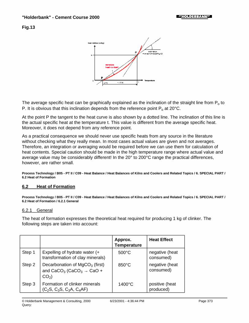
"Holderbank" - Cement Course 2000
© Holderbank Management & Consulting, 2000 6/23/2001 - 4:36:44 PM Page 373Query:
Fig.13
The average specific heat can be graphically explained as the inclination of the straight line from Po toP. It is obvious that this inclination depends from the reference point Po at 20°C.
At the point P the tangent to the heat curve is also shown by a dotted line. The inclination of this line isthe actual specific heat at the temperature t. This value is different from the average specific heat.Moreover, it does not depend from any reference point.
As a practical consequence we should never use specific heats from any source in the literaturewithout checking what they really mean. In most cases actual values are given and not averages.Therefore, an integration or averaging would be required before we can use them for calculation ofheat contents. Special caution should be made in the high temperature range where actual value andaverage value may be considerably different! In the 20° to 200°C range the practical differences,however, are rather small.
Process Technology / B05 - PT II / C09 - Heat Balance / Heat Balances of Kilns and Coolers and Related Topics / 6. SPECIAL PART /6.2 Heat of Formation
6.2 Heat of Formation
Process Technology / B05 - PT II / C09 - Heat Balance / Heat Balances of Kilns and Coolers and Related Topics / 6. SPECIAL PART /6.2 Heat of Formation / 6.2.1 General
6.2.1 General
The heat of formation expresses the theoretical heat required for producing 1 kg of clinker. Thefollowing steps are taken into account:
Approx.Temperature
Heat Effect
Step 1 Expelling of hydrate water (+transformation of clay minerals)
∼ 500°C negative (heatconsumed)
Step 2 Decarbonation of MgCO3 (first)and CaCO3 (CaCO3 → CaO +CO2)
∼ 850°C negative (heatconsumed)
Step 3 Formation of clinker minerals(C2S, C3S, C3A, C4AF)
∼ 1400°C positive (heatproduced)

"Holderbank" - Cement Course 2000
© Holderbank Management & Consulting, 2000 6/23/2001 - 4:36:45 PM Page 374Query:
The net heat produced by the overall reaction is negative i.e. heat is consumed (listed as output).
The heat formation is defined at 20°C. In other words it expresses the theoretical amount of heat totransform raw meal at 20°C to 1 kg clinker at 20°C (if no heat losses would occur). It is therefore alsoconsidered as the theoretical minimum heat required for burning clinker.
The heat of formation is not at all depending on the way of the actual reaction (i.e. temperature versustime). The only precondition of course is that the reactions (step 1, 2, 3) have really been completed.
Although the basic principle of the heat of formation seems quite simple a few conventions (ordefinitions) are necessary here:
1) The hydrate water is expelled is considered as vapour (therefore no additional heat of evaporationhas to be introduced into the balance!).
2) As a „standard case“ the assumption is made that the CaO is present as CaCO3 in the raw meal (innon carbonatic CaO occurs we do not change the heat of formation, but add heat inputs accordingto paragraph 4.7).
3) Burnable components in the raw mix are considered separately as inputs (see paragraph 4.4.2).
Process Technology / B05 - PT II / C09 - Heat Balance / Heat Balances of Kilns and Coolers and Related Topics / 6. SPECIAL PART /6.2 Heat of Formation / 6.2.2 Calculation of Heat of Formation
6.2.2 Calculation of Heat of Formation
Process Technology / B05 - PT II / C09 - Heat Balance / Heat Balances of Kilns and Coolers and Related Topics / 6. SPECIAL PART /6.2 Heat of Formation / 6.2.2 Calculation of Heat of Formation / 6.2.2.1 Introduction
6.2.2.1 Introduction
It is difficult to determine the heat of formation directly be calorimetric measurements. Thereforecalculation methods have been developed in order to take into account the varying influences of rawmix properties.
Although formulas are given the following they should be applied with care. As long as the raw mixdoes not clearly deviate from the „standard“ value of ∼ 1750 kJ/kg the calculated figures must notnecessarily give more accurate results than the 1750 kJ/kg.
Even extensive formulas for heat of formation contain a certain incertitude due to the partial lack ofaccurate thermodynamic standard values (for the minerals which are involved).
Process Technology / B05 - PT II / C09 - Heat Balance / Heat Balances of Kilns and Coolers and Related Topics / 6. SPECIAL PART /6.2 Heat of Formation / 6.2.2 Calculation of Heat of Formation / 6.2.2.2 Calculation Formulas
6.2.2.2 Calculation Formulas
The following formulas are partly based on the work of H. zur Strassen (Lit. 1) however a few recentadaptations have been made:
We will use the following notation:
CaO, MgO, SiO2, Fe2O3, Al2O3 = Clinker analysis, expressed as weight fractions (kg/kg cli)

"Holderbank" - Cement Course 2000
© Holderbank Management & Consulting, 2000 6/23/2001 - 4:36:45 PM Page 375Query:
H2O (kg/kg cli) = Hydrate water in raw material, referred to kg clinker (not to raw meal)
The following general formula for the heat of formation applies:
h = CaO · 3200 + MgO · 2710 - SiO2 · 2140 - Fe2O3 · 250 + hRes (kJ/kg cli)
The last contribution „hRes“ depends on the Al2O3 and H2O (hydrate) content. The calculation of „hRes“depends on the information which is available on hydrate water and/or type of clay. Usually, the moreinformation is known the better the result will be.
CaseNo.
Hydrate Water(H2O)
Type ofClay
Formula for hRes (kJ/kg cli)
1 not known not known hRes = Al2O3 . 1720
2 known not known hRes = Al2O3 . 120
+ H2O . 5520
3 not known known hRes = (Al2O3)K . 2220
+ (Al2O3)M . 1310
+ (Al2O3)I . 1640
4 known known hRes = (Al2O3)K . 1400
+ (Al2O3)M . 620
+ (Al2O3)I . 760
+ H2O . 2450
In case 3 and 4 a distinction has to be made from which type of clay the Al2O3 originates. The indicesK, M, I denote:
K = Kaolinite
M = Montmorillonite
I = Illite
Note on the formulas for hRes:
No. 1:For general purposes, if no information on hydrate water available.
No. 2:Takes into account the actual hydrate water content. It is also a very good approach if the hydratewater does not only originate from clays but for example from Ca(OH)2.Note that the coefficient for H2O (hydrate) is more than twice the normal heat of evaporation 1)
Nos. 3 + 4:Take into account the type of clay. (Hydrate water must originate from clay only, otherwise take No. 2).
When the CaO is introduced into the formula it is not required to know whether the CaO results fromCaCO3 or not. If any non carbonatic CaO is entering into the system we will take into account abalance heat input by definition (see paragraph 4.7) and therefore the calculated heat of formation is

"Holderbank" - Cement Course 2000
© Holderbank Management & Consulting, 2000 6/23/2001 - 4:36:46 PM Page 376Query:
not affected.
1) The older formula from H. zur Strassen did allocate only 2450 kJ to H2O, but instead 930 kJ tothe Al2O3, which made it difficult to extrapolate it for other hydrates than from clay. It is certainly morelogical to refer the heat to the H2O, which is actually responsible for the heat consumption.
Examples
1) - Clinker composition:
CaO = 64.8 %
MgO = 1.2 %
SiO2 = 22.6 %
Fe2O3 = 3.3 %
Al2O3 = 5.2 %
SO3 = 0.52% TiO2 = 0.29%
Na2O = 0.08% Mn2O3 = 0.03%
K2O = 1.20% L.o.I = 0.54%
- No information on hydrate water in raw meal available
h = 0.648 · 3200 + 0.012 · 2710 - 0.226 · 2140 - 0.033 · 250 + 0.052 · 1720 = 1704 kJ/kg cli
2) -Clinker composition:CaO = 65.2 %
MgO = 1.2 %
SiO2 = 22.9 %
Fe2O3 = 3.0 %
Al2O3 = 5.0 %
- Raw material = 1.1% hydrate water R = 1.57 kg/kg → 0.017 kg hydrate water/kg clinkerh = 0.652 · 3200 + 0.012 · 2710 - 0.229 · 2140 - 0.03 · 250 + 0.050 · 120 + 0.017 · 5520 = 1721 kJ/kg cli
Process Technology / B05 - PT II / C09 - Heat Balance / Heat Balances of Kilns and Coolers and Related Topics / 6. SPECIAL PART /6.2 Heat of Formation / 6.2.2 Calculation of Heat of Formation / 6.2.2.3 Sulfatization Effects
6.2.2.3 Sulfatization Effects
The SO2 can react with the alkalis K2O or Na2O (but also with CaO). For the heat effect the following

"Holderbank" - Cement Course 2000
© Holderbank Management & Consulting, 2000 6/23/2001 - 4:36:46 PM Page 377Query:
(simplified) reaction is considered as typical:
Na2O + SO2 + ½ O2 → Na2SO4 + heat
(molar heat effects of K2O and Na2O are of similar size!)
The overall degree of sulfatization reactions is usually not known. For the heat effect the followinglower and upper boundaries can be calculated:
lower boundary = - 8370 · [(SO3)cli + (SO3)D - (SO3)R] (kJ/kg cli)upper boundary = - 10800 · [(Na2O)R - (Na2O)cli] - 7120 · [(K2O)R - (K2O)cli] + 8370 · [(SO3)R - (SO3)cli] (kJ/kg cli)
where SO3, Na2O, K2O are expressed as kg/kg cli (referred to clinker!).
The indices denote: cli = in clinker D = in dust R = in raw meal
An average value can be introduced into the heat balance. Preferably this item is just listed under theitem heat of formation (under output). Its sign is then negative, i.e. the outputs are reduced.
Process Technology / B05 - PT II / C09 - Heat Balance / Heat Balances of Kilns and Coolers and Related Topics / 6. SPECIAL PART /6.2 Heat of Formation / 6.2.2 Calculation of Heat of Formation / 6.2.2.4 Lime Kilns
6.2.2.4 Lime Kilns
The formula for heat of formation of burnt lime is quite similar to that of cement clinker.
The following main reactions are taken into account:
CaCO3 → CaO + CO2
MgCO3 → MgO + CO2
CaO + 2 SiO2 → C2S (dicalciumilicate)
Unlike on cement clinker the CaO in the lime product does not exclusively consist of „non carbonatic“CaO, but some residual CaCO3 is also present. Therefore the non carbonatic proportion CaOnc has tobe calculated first:
CaOnc = CaOtot - CO2 · (56/44)
The heat of formation becomes:
h = CaOnc · 3150 + MgO · 2710 - SiO2 . 2100 (kJ/kg lime)
CaOnc, MgO, SiO2 denote the weight fractions in lime product.
If the lime is present in lump form and the SiO2 does originate e.g. from coal ash it is unlikely that C2Smineral is formed. In such cases only the SiO2 which comes from the limestone feed has to beconsidered in the formula.
Process Technology / B05 - PT II / C09 - Heat Balance / Heat Balances of Kilns and Coolers and Related Topics / 6. SPECIAL PART /6.3 Radiation Heat Transfer
6.3 Radiation Heat Transfer
The basic radiation formula is

"Holderbank" - Cement Course 2000
© Holderbank Management & Consulting, 2000 6/23/2001 - 4:36:47 PM Page 378Query:
Qf = CR · ε · A [ (T/100)4 - (T0/100)4 ] [W]
Qf = heat flow [W]CR = radiation constant = 5.67 W/m2K4
ε = emissivity (0...1)A = radiating area (m2)T = absolute temperature of radiating surface [K] (T = 273+t)To = absolute temperature of ambient [K]
Strictly speaking above formula is only valid for cylinders of infinite length which radiate towards anambient which is far away from the cylinder. No obstacles may shield off the radiation.
Though its simplifications this formula may be taken as a good approach for most cases.
By dividing Qf by T - To and A, the ∝-value (heat transfer coefficient) can be obtained:
)/(100100
24
04
0
CmWTT
TTCR
−
−⋅
=ε
α
Or alternatively the following formula, which is identical to the latter comes out:
)/(41
1100100
4 223
CmWTTT
CR
∆
+
⋅⋅= εα
20TT
T+
= = average temperature (K)
0TTT −=∆ = temperature difference (K or C)
From the second formula it becomes evident that (at small temperature differences) ∝ increases withthe third (not fourth!) power of the average temperature. In addition, the ∝-value does convergetowards a finite value at zero temperature difference.
For practical evaluation of the ∝ (radiation) Fig. 9 (see paragraph 4.10.2) is available. It is based on aconstant ambient temperature of To = 293 K (20°).
If the true ambient temperature is actually not exactly 20°C one commits a slight error. Usually this canbe neglected. In some extreme or exceptional cases the above formulas can be used for calculations.
Since the emissivity ε is often not known precisely and does also depend on the temperature it isusually not worthwhile to do small corrections on the ∝-values obtained from Fig. 9.
Process Technology / B05 - PT II / C09 - Heat Balance / Heat Balances of Kilns and Coolers and Related Topics / 6. SPECIAL PART /6.4 Convective Heat Transfer
6.4 Convective Heat Transfer
Process Technology / B05 - PT II / C09 - Heat Balance / Heat Balances of Kilns and Coolers and Related Topics / 6. SPECIAL PART /6.4 Convective Heat Transfer / 6.4.1 Free Convection
6.4.1 Free Convection
Free convection occurs due to density differences between hot air (at the shell surface) and ambient

"Holderbank" - Cement Course 2000
© Holderbank Management & Consulting, 2000 6/23/2001 - 4:36:48 PM Page 379Query:
air. A natural updraft causes a convective air movement.
For vertical plates or horizontal cylinders the following relationship applies:
Nu = 0.13 (Pr . Gr) 1/3 (-)where: Nu = αD / λ = Nusselt number (-)
Pr = cpη / λ = Prandtl number (-)
02
23
TTgD
Gr⋅
∆⋅⋅⋅=
ηρ
= Grashof number (-)
∝ (W/m2K) heat transfer coefficient
D (m) characteristical dimension *
λ (W/mK) heat conductivity
cp (J/kg K) specific heat
g (m/s2) gravity constant = 9.81 m/s2
ρ (kg/m3) gas density
∆T (K) temperature difference (T - To)
η (kg/ms) dynamic viscosity
To (K) absolute ambient temperature
* for a cylinder with diameter d → D = (Π/2) · d
Application range: Pr · Gr > 109
As long as there is a minimum temperature difference of a few degrees and the diameter range is over1 m, above limitation does not affect the calculation.
A mathematical transformation of the basic equation reveals that the free convection heat transferdoes not at all depend on the characteristical dimension! It follows:
)/(13.0 231
0
31
22
KmWTTgcp
∆
⋅⋅⋅=
ηδλ
α
At ∆T = 0 the free convection becomes zero (which is different from the behavior of the radiation heattransfer!).
The numerical values for cp, λ, ρ, η must be taken from tables for air at the average temperaturebetween surface and ambient (use SI-units only).
Note that the density ρ depends also on the barometric pressure and therefore the result will dependon the altitude above sea level (∝ ∼ p2/3). As a general guideline the convective heat transfer drops byabout 8% per 1000 m of altitude.
By using numerical approximations for the properties of air the following relationship has beendeveloped (dimensional equation):
α ≅ 1.4 · (ρ0 · ρ · ∆T)1/3 (W/m2K)
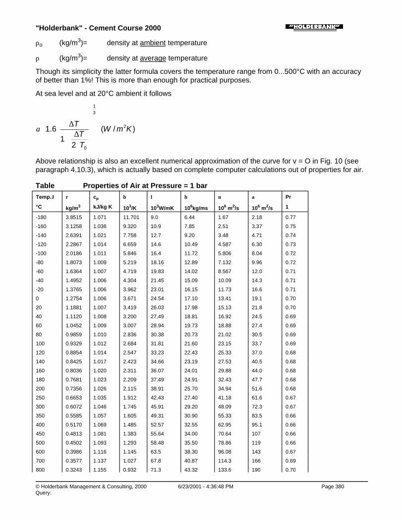
"Holderbank" - Cement Course 2000
© Holderbank Management & Consulting, 2000 6/23/2001 - 4:36:48 PM Page 380Query:
ρo (kg/m3)= density at ambient temperature
ρ (kg/m3)= density at average temperature
Though its simplicity the latter formula covers the temperature range from 0...500°C with an accuracyof better than 1%! This is more than enough for practical purposes.
At sea level and at 20°C ambient it follows
)/(
21
6.1 2
31
0
KmW
TT
T
⋅∆
+
∆≅α
Above relationship is also an excellent numerical approximation of the curve for v = O in Fig. 10 (seeparagraph 4.10.3), which is actually based on complete computer calculations out of properties for air.
Table Properties of Air at Pressure = 1 barTemp.ϑ ρ cp β λ η ν α Pr
°C kg/m3 kJ/kg K 103/K 103W/mK 106kg/ms 106 m2/s 106 m2/s 1
-180 3.8515 1.071 11.701 9.0 6.44 1.67 2.18 0.77
-160 3.1258 1.036 9.320 10.9 7.85 2.51 3.37 0.75
-140 2.6391 1.021 7.758 12.7 9.20 3.48 4.71 0.74
-120 2.2867 1.014 6.659 14.6 10.49 4.587 6.30 0.73
-100 2.0186 1.011 5.846 16.4 11.72 5.806 8.04 0.72
-80 1.8073 1.009 5.219 18.16 12.89 7.132 9.96 0.72
-60 1.6364 1.007 4.719 19.83 14.02 8.567 12.0 0.71
-40 1.4952 1.006 4.304 21.45 15.09 10.09 14.3 0.71
-20 1.3765 1.006 3.962 23.01 16.15 11.73 16.6 0.71
0 1.2754 1.006 3.671 24.54 17.10 13.41 19.1 0.70
20 1.1881 1.007 3.419 26.03 17.98 15.13 21.8 0.70
40 1.1120 1.008 3.200 27.49 18.81 16.92 24.5 0.69
60 1.0452 1.009 3.007 28.94 19.73 18.88 27.4 0.69
80 0.9859 1.010 2.836 30.38 20.73 21.02 30.5 0.69
100 0.9329 1.012 2.684 31.81 21.60 23.15 33.7 0.69
120 0.8854 1.014 2.547 33.23 22.43 25.33 37.0 0.68
140 0.8425 1.017 2.423 34.66 23.19 27.53 40.5 0.68
160 0.8036 1.020 2.311 36.07 24.01 29.88 44.0 0.68
180 0.7681 1.023 2.209 37.49 24.91 32.43 47.7 0.68
200 0.7356 1.026 2.115 38.91 25.70 34.94 51.6 0.68
250 0.6653 1.035 1.912 42.43 27.40 41.18 61.6 0.67
300 0.6072 1.046 1.745 45.91 29.20 48.09 72.3 0.67
350 0.5585 1.057 1.605 49.31 30.90 55.33 83.5 0.66
400 0.5170 1.069 1.485 52.57 32.55 62.95 95.1 0.66
450 0.4813 1.081 1.383 55.64 34.00 70.64 107 0.66
500 0.4502 1.093 1.293 58.48 35.50 78.86 119 0.66
600 0.3986 1.116 1.145 63.5 38.30 96.08 143 0.67
700 0.3577 1.137 1.027 67.8 40.87 114.3 166 0.69
800 0.3243 1.155 0.932 71.3 43.32 133.6 190 0.70

"Holderbank" - Cement Course 2000
© Holderbank Management & Consulting, 2000 6/23/2001 - 4:36:50 PM Page 381Query:
800 0.3243 1.155 0.932 71.3 43.32 133.6 190 0.70
900 0.2967 1.171 0.852 74.3 45.65 153.9 214 0.72
1000 0.2734 1.185 0.786 76.8 47.88 175.1 237 0.7
↓
(actual cp, not average)
Process Technology / B05 - PT II / C09 - Heat Balance / Heat Balances of Kilns and Coolers and Related Topics / 6. SPECIAL PART /6.4 Convective Heat Transfer / 6.4.2 Forced Convection
6.4.2 Forced Convection
Forced convection occurs at comparatively high wind velocity and dominates the convective heattransfer, i.e. the free convection is suppressed.
The calculation of forced convection is depending on many factors, such as:
♦ Wind velocity
♦ Direction of the wind
♦ Velocity distribution and flow obstacles
♦ Uniformity of wind
♦ Reynolds number (depends on kiln diameter).
There are a few more influence factors than in case of the free convection. Generally speaking thecalculation of forced convection heat transfer contains more possible sources of error than freeconvection.
As a simplification, we will assume a cylinder in a non disturbed flow of a constant velocity v (at 90°against kiln axis).
Fig. 14
For air the following formula apply:
Nu = 0.0239 · Re 0.805 for Re = 40’000...400’000
Nu = 0.00672 · Re 0.905 for Re > 400’000

"Holderbank" - Cement Course 2000
© Holderbank Management & Consulting, 2000 6/23/2001 - 4:36:51 PM Page 382Query:
NumberNusseltD
Nu
NumberynoldsDvvD
==
=⋅⋅
==
λα
ηρ
νReRe
The properties η, λ, ϑ have to be taken at average air temperature.
There are other formulas in use which can give different results, the above formulas are preferred dueto their simplicity. In any case there is always a incertitude from the mode of calculation itself.
Two main factors determine the ∝-value:
♦ Velocity v
♦ Average temperature (between surface and ambient)
In addition the ∝ does also depend on the diameter D. If the equation for high Reynolds number (Re >400’000) is solved for ∝, the following relationship is obtained:
∝ ∼ D-0.095
↓ proportional
This means that the ∝ value does not much depend on D! Therefore it is possible to work with constantvalues within a certain diameter range.
This actually the base of Fig. 10 (see paragraph 4.10.3) which is calculated for a common range from3...4...6 m diameter.
Process Technology / B05 - PT II / C09 - Heat Balance / Heat Balances of Kilns and Coolers and Related Topics / 6. SPECIAL PART /6.4 Convective Heat Transfer / 6.4.3 Free Convection Plus Forced Convection
6.4.3 Free Convection Plus Forced Convection
If the convection is clearly dominated either by free or forced convection the final determination of therepresentative ∝ does not give any problem, since the higher value has to be taken.
If the two values are of the same order they must be combined with an appropriate method. It would becertainly wrong to add the two values. A better approach is the square addition:
forcedfreetot22 ααα +=
It is also valid if either the free convection or the forced convection dominates.
Fig. 10 is based on the above method.
Process Technology / B05 - PT II / C09 - Heat Balance / Heat Balances of Kilns and Coolers and Related Topics / 6. SPECIAL PART /6.5 Effect of Thermal Improvements
6.5 Effect of Thermal Improvements
According to the actual condition of an existing kiln system (heat consumption, heat balance, otheroperating data) we can envisage an optimization campaign. From the thermal point of view we cantake certain measures in order to reduce the specific heat consumption. For example:
♦ Better insulation of rotary kiln or preheater/precalciner in order to reduce radiation losses (exceptthe sintering zone).

"Holderbank" - Cement Course 2000
© Holderbank Management & Consulting, 2000 6/23/2001 - 4:36:51 PM Page 383Query:
♦ Improvement of the cooler efficiency (optimization of grate cooler operation or installation of highlyefficient internal equipment in planetary or rotary cooler).
♦ Reducing of false air inleaks at kiln seals or at preheater.
♦ Reducing of internal dust circulations in cooler, kiln or preheater (improves the internalcounter-current heat transfer).
♦ Modification of raw mix in order to decrease the sintering temperature which in turn will also reduceheat losses. A further effect of such a measure can be the reduction of internal dust circulationsdue to better clinker granulometry (see above).
♦ Modification of raw mix in order to decrease the heat required for decarbonation, e.g. by makinguse of non-carbonatic CaO raw material sources. This possibility, however, is very rare and oftennot feasible. (Note the basic difference to the measures which tend to decrease the sinteringtemperature or increase the proportion of melting phase!)
The above measures are just a few typical examples. When one goes into such items, an importantphenomenon will appear soon: The so called „loss multiplication“ factor for thermal losses (or savings).What does this mean?
If a saving (or loss) in the high temperature zone in a kiln of say 100 kJ occurs the possible gain in fuelheat consumption will not be 100 kJ but rather 130 to 150 kJ. That means that the primary saving (interms of heat balance item) will be multiplied by a factor of up to 1.5.
At the first glance the above principle seems to be contradicious because it would violate the principleof heat balance or the energy law. However, what really happens is a differential change of more thanonly one heat balance item. To illustrate this fact we start from an example where we have reduced theshell radiation losses by 100 kJ/kg cli.
The following differential balance situation occurs:
Fig. 15
The corresponding multiplication factor for the above case is:
multiplication factor = - 140 kJ/kg = 1.40 - 100 kJ/kg
The above fact does result from the thermal behavior of the system and can be verified by simulationmodels (not by a simple balance only).

"Holderbank" - Cement Course 2000
© Holderbank Management & Consulting, 2000 6/23/2001 - 4:36:52 PM Page 384Query:
A factor in the 1.4-range is quite typical for the situation in the high temperature zone (above 800°C) ofa cement kiln. The main effect of a change in this zone will be a corresponding change at the exhaustgas, but also other minor effects will occur (e.g. at cooler losses).
A “differential balance“ of heat can still be applied according to:
Input Change Output Change
fuel = - 140 kJ/kg radiation = - 100 kJ/kg
exhaust = - 40 kJ/kg
total = - 140 kJ/kg total = - 140 kJ/kg
The principle of loss multiplication does not only apply for radiation in the high temperature zone butalso for the heat which is recuperated in the clinker cooler.
Regarding the false air inleaks the corresponding deterioration of heat consumption is oftenunder-estimated. If false air inleaks into the high temperature zone it does not only cause a heat lossbecause this air must be heated up to the exhaust gas temperature of the kiln system! It actuallycauses much more losses than what would result from such a simplified calculation approach. As arule of thumb we may consider the following two main effects in order to come to a realistic result:
♦ Heating up of false air at the temperature of the high temperature zone which can be setapproximately to 800°C (end of HT-zone).
♦ Multiplication of the above heat requirement by a loss multiplication factor.
The above calculation is a rough approach. By more sophisticated simulation models we find e.g. thata false air inleak into the high temperature zone of 0.08 Nm3/kg cli can cause an additional heatconsumption of 100 kJ/kg cli. In contrast, the inleak in the low temperature zone (e.g. air lift on SP-kiln)is much less critical.
Process Technology / B05 - PT II / C09 - Heat Balance / Heat Balances of Kilns and Coolers and Related Topics / 6. SPECIAL PART /6.6 Heat Transfer in Preheaters and Coolers and Improvement Potential
6.6 Heat Transfer in Preheaters and Coolers and Improvement Potential
Normally we are considering a cement kiln as an equipment for burning cement clinker. As an essentialfeature we must be able to generate a high sintering temperature in the order of 1450°C (materialtemperature).
But a kiln system is of course much more than a generator of sintering temperature. It is also a systemof heat exchangers which allows for burning at low heat consumption. Generally speaking we will findtwo essential heat-exchanging systems on any cement kiln:
a) raw meal preheater
b) clinker cooler
Low heat consumption is only possible if the above two „heat exchangers“ perform optimally.
How can we get optimum heat exchange performance? Form the basic theory it is known that even in
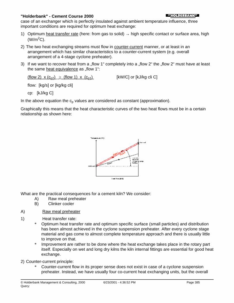
"Holderbank" - Cement Course 2000
© Holderbank Management & Consulting, 2000 6/23/2001 - 4:36:52 PM Page 385Query:
case of an exchanger which is perfectly insulated against ambient temperature influence, threeimportant conditions are required for optimum heat exchange:
1) Optimum heat transfer rate (here: from gas to solid) → high specific contact or surface area, high ∝(W/m2C).
2) The two heat exchanging streams must flow in counter-current manner, or at least in anarrangement which has similar characteristics to a counter-current system (e.g. overallarrangement of a 4-stage cyclone preheater).
3) If we want to recover heat from a „flow 1“ completely into a „flow 2“ the „flow 2“ must have at leastthe same heat equivalence as „flow 1“:
(flow 2) x (cp2) ≥ (flow 1) x (cp1) [kW/C] or [kJ/kg cli C]
flow: [kg/s] or [kg/kg cli]
cp: [kJ/kg C]
In the above equation the cp values are considered as constant (approximation).
Graphically this means that the heat characteristic curves of the two heat flows must be in a certainrelationship as shown here:
What are the practical consequences for a cement kiln? We consider: A) Raw meal preheater B) Clinker cooler
A) Raw meal preheater
1) Heat transfer rate:∗ Optimum heat transfer rate and optimum specific surface (small particles) and distribution
has been almost achieved in the cyclone suspension preheater. After every cyclone stagematerial and gas come to almost complete temperature approach and there is usually littleto improve on that.
∗ Improvement are rather to be done where the heat exchange takes place in the rotary partitself. Especially on wet and long dry kilns the kiln internal fittings are essential for good heatexchange.
2) Counter-current principle:∗ Counter-current flow in its proper sense does not exist in case of a cyclone suspension
preheater. Instead, we have usually four co-current heat exchanging units, but the overall
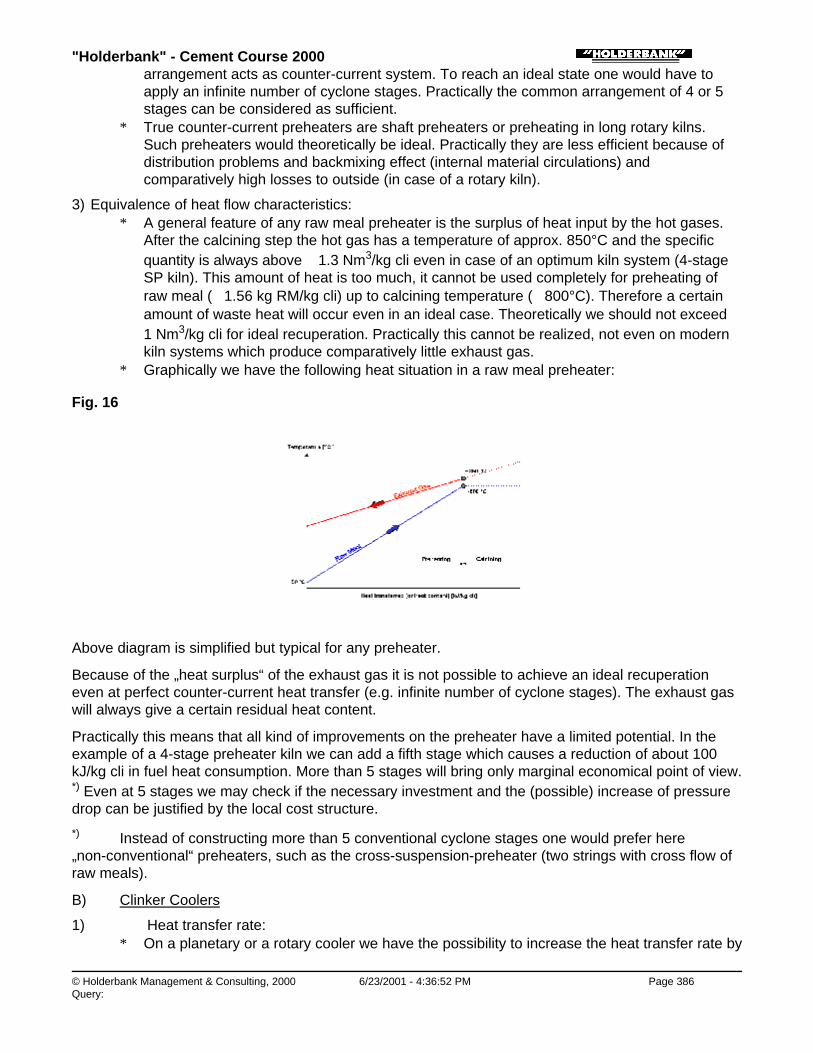
"Holderbank" - Cement Course 2000
© Holderbank Management & Consulting, 2000 6/23/2001 - 4:36:52 PM Page 386Query:
arrangement acts as counter-current system. To reach an ideal state one would have toapply an infinite number of cyclone stages. Practically the common arrangement of 4 or 5stages can be considered as sufficient.
∗ True counter-current preheaters are shaft preheaters or preheating in long rotary kilns.Such preheaters would theoretically be ideal. Practically they are less efficient because ofdistribution problems and backmixing effect (internal material circulations) andcomparatively high losses to outside (in case of a rotary kiln).
3) Equivalence of heat flow characteristics:∗ A general feature of any raw meal preheater is the surplus of heat input by the hot gases.
After the calcining step the hot gas has a temperature of approx. 850°C and the specificquantity is always above ∼ 1.3 Nm3/kg cli even in case of an optimum kiln system (4-stageSP kiln). This amount of heat is too much, it cannot be used completely for preheating ofraw meal (∼ 1.56 kg RM/kg cli) up to calcining temperature (∼ 800°C). Therefore a certainamount of waste heat will occur even in an ideal case. Theoretically we should not exceed ∼1 Nm3/kg cli for ideal recuperation. Practically this cannot be realized, not even on modernkiln systems which produce comparatively little exhaust gas.
∗ Graphically we have the following heat situation in a raw meal preheater:
Fig. 16
Above diagram is simplified but typical for any preheater.
Because of the „heat surplus“ of the exhaust gas it is not possible to achieve an ideal recuperationeven at perfect counter-current heat transfer (e.g. infinite number of cyclone stages). The exhaust gaswill always give a certain residual heat content.
Practically this means that all kind of improvements on the preheater have a limited potential. In theexample of a 4-stage preheater kiln we can add a fifth stage which causes a reduction of about 100kJ/kg cli in fuel heat consumption. More than 5 stages will bring only marginal economical point of view.*) Even at 5 stages we may check if the necessary investment and the (possible) increase of pressuredrop can be justified by the local cost structure.
*) Instead of constructing more than 5 conventional cyclone stages one would prefer here„non-conventional“ preheaters, such as the cross-suspension-preheater (two strings with cross flow ofraw meals).
B) Clinker Coolers
1) Heat transfer rate:∗ On a planetary or a rotary cooler we have the possibility to increase the heat transfer rate by
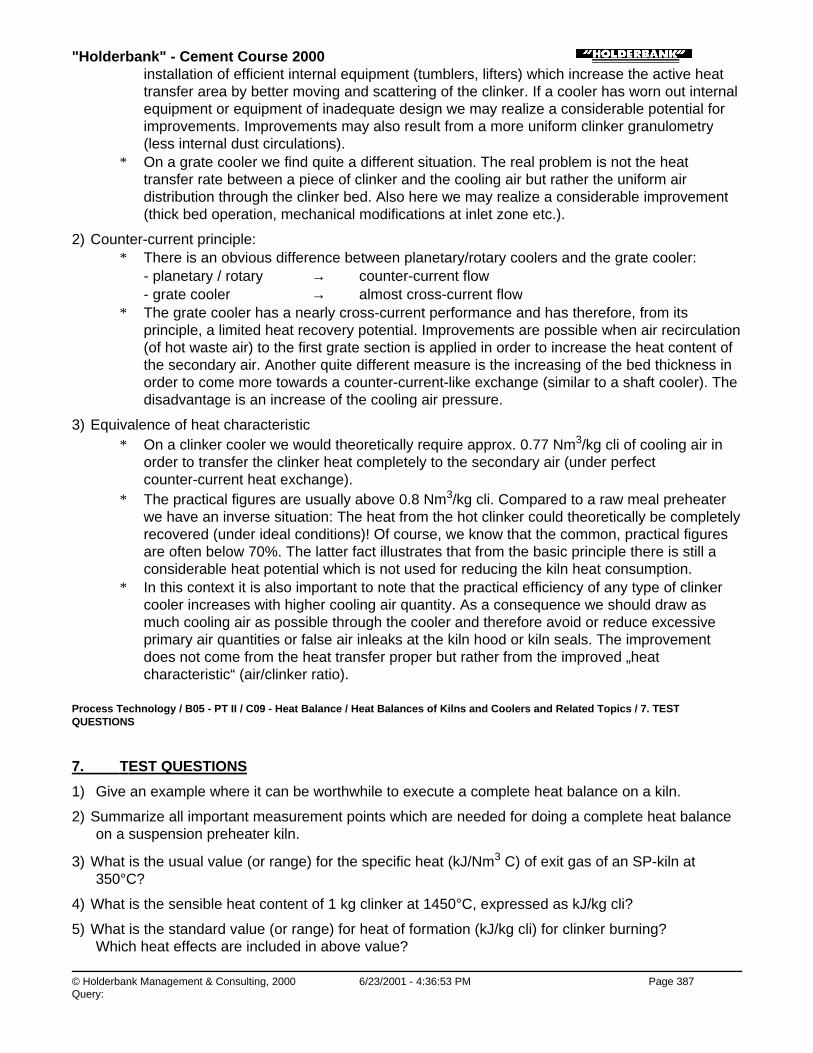
"Holderbank" - Cement Course 2000
© Holderbank Management & Consulting, 2000 6/23/2001 - 4:36:53 PM Page 387Query:
installation of efficient internal equipment (tumblers, lifters) which increase the active heattransfer area by better moving and scattering of the clinker. If a cooler has worn out internalequipment or equipment of inadequate design we may realize a considerable potential forimprovements. Improvements may also result from a more uniform clinker granulometry(less internal dust circulations).
∗ On a grate cooler we find quite a different situation. The real problem is not the heattransfer rate between a piece of clinker and the cooling air but rather the uniform airdistribution through the clinker bed. Also here we may realize a considerable improvement(thick bed operation, mechanical modifications at inlet zone etc.).
2) Counter-current principle:∗ There is an obvious difference between planetary/rotary coolers and the grate cooler:
- planetary / rotary → counter-current flow- grate cooler → almost cross-current flow
∗ The grate cooler has a nearly cross-current performance and has therefore, from itsprinciple, a limited heat recovery potential. Improvements are possible when air recirculation(of hot waste air) to the first grate section is applied in order to increase the heat content ofthe secondary air. Another quite different measure is the increasing of the bed thickness inorder to come more towards a counter-current-like exchange (similar to a shaft cooler). Thedisadvantage is an increase of the cooling air pressure.
3) Equivalence of heat characteristic∗ On a clinker cooler we would theoretically require approx. 0.77 Nm3/kg cli of cooling air in
order to transfer the clinker heat completely to the secondary air (under perfectcounter-current heat exchange).
∗ The practical figures are usually above 0.8 Nm3/kg cli. Compared to a raw meal preheaterwe have an inverse situation: The heat from the hot clinker could theoretically be completelyrecovered (under ideal conditions)! Of course, we know that the common, practical figuresare often below 70%. The latter fact illustrates that from the basic principle there is still aconsiderable heat potential which is not used for reducing the kiln heat consumption.
∗ In this context it is also important to note that the practical efficiency of any type of clinkercooler increases with higher cooling air quantity. As a consequence we should draw asmuch cooling air as possible through the cooler and therefore avoid or reduce excessiveprimary air quantities or false air inleaks at the kiln hood or kiln seals. The improvementdoes not come from the heat transfer proper but rather from the improved „heatcharacteristic“ (air/clinker ratio).
Process Technology / B05 - PT II / C09 - Heat Balance / Heat Balances of Kilns and Coolers and Related Topics / 7. TESTQUESTIONS
7. TEST QUESTIONS
1) Give an example where it can be worthwhile to execute a complete heat balance on a kiln.
2) Summarize all important measurement points which are needed for doing a complete heat balanceon a suspension preheater kiln.
3) What is the usual value (or range) for the specific heat (kJ/Nm3 C) of exit gas of an SP-kiln at350°C?
4) What is the sensible heat content of 1 kg clinker at 1450°C, expressed as kJ/kg cli?
5) What is the standard value (or range) for heat of formation (kJ/kg cli) for clinker burning?Which heat effects are included in above value?

"Holderbank" - Cement Course 2000
© Holderbank Management & Consulting, 2000 6/23/2001 - 4:36:53 PM Page 388Query:
6) Determine the heat transfer coefficient (W/m2C) for the total heat transfer by radiation plus freeconvection. The temperature of the kiln shell section is 200°C (ambient = 20°C, ε = 0.9).
7) When has the forced convection heat transfer (instead of free convection) to be considered?How is the above value affected in case of smaller dimensions (say 1 m instead of 5 m diameter)?
8) If the shell losses in the calcining zone can be reduced by 50 kJ/kg cli, what will be the approximatesaving of fuel heat (kJ/kg cli)?
9) What is the approximate fuel heat which can be saved through the installation of a fifth cyclonestage on a suspension preheater kiln?What would be the approximate amount of false air reduction (Nm3/kg cli into the high temperaturezone) in order to achieve a similar fuel heat saving?
Process Technology / B05 - PT II / C09 - Heat Balance / Heat Balances of Kilns and Coolers and Related Topics / 8. LITERATURE
8. LITERATURE
1) Zur Strassen, H.Der theoretische Wärmebedarf des ZementbrandesZKG 10 (1957), Vol. 1, p. 1-12
1) Jakob, M.Heat transfer, Vol. I (1949), p. 529
2) Hilpert, R.Wärmeabgabe von geheizten Drähten und Rohren im LuftstromForsch.-Ing.-Wes., Vol. 4 (1939), p. 215-224
3) Gygi, H.Thermodynamics of the cement kiln, third industrial symposium on the chemistry of cement
4) Eigen, H.Beitrag zur Thermodynamik des DrehofensTonindustrie-Zeitung 82 (1958), No. 16, p. 337-341
5) Frankenberger, R.Beitrag zur Berechnung des Wärmeübergangs in ZementdrehöfenDissertation, Technische Universität Clausthal (1969)
6) Kühle, W.Untersuchung über die äussere Wärmeabgabe von Drehöfen durch Strahlung und KonvektionZement-Kalk-Gips, Vol. 6, 1970, p. 263
7) VDZ Unterlagen„Wärmetechnische Berechnungen“Verein Deutscher Zementwerke E.V., Düsseldorf
8) VDI-WärematlasBerechnungsblätter für den WäremübergangVDI-Verlag GmbH, Düsseldorf
9) Barin, I. and Knacke, O.Thermochemical properties of inorganic substancesSpringer Verlag, Berlin, Heidelberg, New York
10) Elkajer, P. (FLS)Die Bestimmung des Wärmeverbrauches mit vierstufigem Zyklonvorwärmer durch Aufstellung

"Holderbank" - Cement Course 2000
© Holderbank Management & Consulting, 2000 6/23/2001 - 4:36:54 PM Page 389Query:
eines mathematischen ModellesZement-Kalk-Gips, Vol. 2, 1980
11) Gardeik, H.O.Berechnung des Wandwärmeverlustes von Drehöfen und MühlenZement-Kalk-Gips, Vol. 2, 1980
12) Rother, W.Ausführung von Rohmehl-Wärmetauschern unter Berücksichtigung heutiger KostenfaktorenZement-Kalk-Gips, Vol. 2, 1982, p. 66 ff.
Process Technology / B05 - PT II / C09 - Heat Balance / Heat Balances of Kilns and Coolers and Related Topics / 9. SYMBOLS ANDUNITS
9. SYMBOLS AND UNITS
A m2 area
CR W/m2K4 radiation constant
cP kJ/kg C specific heat (at const. pressure),
or kJ/Nm3 C specific heat capacity
CV kJ/kg calorific value
D m diameter
g m/s2 gravity constant
h kJ/kg heat content (specific)
or kJ/Nm3
or kJ/kg cli
L m length
m kg mass
or kg/kg specific mass
mf kg/h mass flow
Qf kW heat flow (1 kW = 1 kJ/s)
t C temperature (Centigrade)
T K temperature (Kelvin)
v m/s velocity
w kg/kg water content
Greek Letters
∝ W/m2K heat transfer coefficient
ε - emissivity (for radiation)
λ W/m C heat conductivity
ρ kg/m3 density
Dimensionless Numbers
Nu Nusselt number (for heat transfer)

"Holderbank" - Cement Course 2000
© Holderbank Management & Consulting, 2000 6/23/2001 - 4:36:54 PM Page 390Query:
Nu Nusselt number (for heat transfer)
Pr Prandtl number
R kiln feed (raw meal) / clinker-ratio
Re Reynolds number
Indices
conv convection
rad radiation
tot total
o ambient condition or zero condition
Conversion Factors
Length 1 inch 0.0254 m
1 ft 0.3048 m
Area 1 sq. ft 0.092903 m2
Volume, Volume Flow 1 cu.ft 0.028316 m3
1 cu.ft/min 1.699 m3/h (actual m3)
Mass 1 lb. 0.45359 kg
1 short ton(USA)
907.185 kg
Pressure 1 bar 105 N/m2
1 atm. 1.013 bar
Energy 1 kJ 1000 J
1 MJ 1000 kJ
1 kWh 3600 kJ
1 kcal 4.187 kJ
1 BTU 1.055 kJ
Temperature Conversion C = 5/9(F - 32)
K = 273.15 + C
Heat Flow 1 kW 1000 W = 1 kJ/s
1 kcal/h 1.163 W
1 BTU/h 0.29307 W
Specific Heat 1 kcal/kg C 4.187 kJ/kg C = 4187 J/kg C
1 BTU/lb F 1 kcal/kg C = 4.187 kJ/kg C
Heat Transfer Coeffic. 1 kcal/m2h C 1.163 W/m2 C
1 BTU/ft2h F 5.678 W/m2C
Standard Conditions forGases
StandardConditions
0°C and 1 atm. (1.013 bar)
barbarp
ctmactNm
013.1)(
)(16.27315.73.2
. 33 ×+
×=

"Holderbank" - Cement Course 2000
© Holderbank Management & Consulting, 2000 6/23/2001 - 4:36:55 PM Page 391Query:

"Holderbank" - Cement Course 2000
© Holderbank Management & Consulting, 2000 6/23/2001 - 4:36:55 PM Page 392Query:
Process Technology / B05 - PT II / C10 - Main Fans
C10 - Main Fans

"Holderbank" - Cement Course 2000
© Holderbank Management & Consulting, 2000 6/23/2001 - 4:36:55 PM Page 393Query:
Process Technology / B05 - PT II / C10 - Main Fans / Main Fans
Main FansAuthors: W. Zeller, Th. Richner, D. BrasselPT 99/14500/E
1. Design and efficiency of fan impellers
1.1 Fan impeller types
1.2 Selection criteria
1.3 Fan applications in the cement industry
2. Fan performance curves
2.1 System Resistance Curve
2.2 Fan curves
2.2.1 Fan equations
2.2.2 Adjusting fan performance curves
3. Flow control
3.1 Damper control
3.2 Radial inlet vane
3.3 Speed control
3.3.1 Hydraulic transmission with fixed speed motor
3.3.2 Speed-controlled electric motors
4. Possible problems with fans
4.1 Vibrations
4.1.1 Variable speed operation
4.1.2 Thermal effects
4.1.3 Hot shutdowns
4.2 Material build-up
4.2.1 Kiln exhaust fan build-up
4.2.2 Recommendations against build-up
4.3 Erosion
4.3.1 Erosion types
4.3.2 Improper duct connection
4.3.3 Effects of impeller speed and wheel inlet velocity
4.4 Wear protection
4.4.1 Protection of parts subjected to abrasion

"Holderbank" - Cement Course 2000
© Holderbank Management & Consulting, 2000 6/23/2001 - 4:36:55 PM Page 394Query:
4.4.2 Deflection of abrasive particles
4.4.3 Liner materials
4.5 Bearings
5. Fan Capacity Adjustment
5.1 Fan capacity too low
5.2 Fan capacity too high
6. Troubleshooting
7. Start-up of fans
8. Fan impeller arrangement and connections
8.1 Assembly
8.1.1 Overhung assembly (Fig. 8.1)
8.1.2 Center hung assembly (Fig. 8.2)
8.2 Foundations
8.3 Connections
8.3.1 Inlet connections
8.3.2 Outlet connections
9. Information Sources
Process Technology / B05 - PT II / C10 - Main Fans / Main Fans / 1. DESIGN AND EFFICIENCY OF FAN IMPELLERS
1. DESIGN AND EFFICIENCY OF FAN IMPELLERS
Fans are essential components of the cement manufacturing process and merit therefore particularconsiderations with respect to
• design and efficiency of the impeller
• fan size and operating point
• flow control
• reliability
Main fans in a Cement Plant are found as
• Kiln ID Fan
• Raw Mill Fan
• Cooler Exhaust Gas Fan
• Kiln Dedusting Fan
Altogether these fans consume between 30 and 50% of the plants total electrical energy.
Process Technology / B05 - PT II / C10 - Main Fans / Main Fans / 1. DESIGN AND EFFICIENCY OF FAN IMPELLERS / 1.1 Fan impellertypes
1.1 Fan impeller types
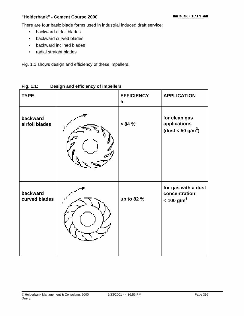
"Holderbank" - Cement Course 2000
© Holderbank Management & Consulting, 2000 6/23/2001 - 4:36:56 PM Page 395Query:
There are four basic blade forms used in industrial induced draft service:
• backward airfoil blades
• backward curved blades
• backward inclined blades
• radial straight blades
Fig. 1.1 shows design and efficiency of these impellers.
Fig. 1.1: Design and efficiency of impellers
TYPE EFFICIENCYη
APPLICATION
backwardairfoil blades > 84 %
for clean gasapplications (dust < 50 g/m3)
backwardcurved blades up to 82 %
for gas with a dustconcentration < 100 g/m3

"Holderbank" - Cement Course 2000
© Holderbank Management & Consulting, 2000 6/23/2001 - 4:36:56 PM Page 396Query:
Backwardinclinedblades
up to 80 %for gas with adustload up to 100 g/m3
radial straightblades 60 - 75 %
for gas with a highdustload (dust > 100 g/m3)
Process Technology / B05 - PT II / C10 - Main Fans / Main Fans / 1. DESIGN AND EFFICIENCY OF FAN IMPELLERS / 1.2 Selectioncriteria
1.2 Selection criteria
It is of great importance that critical process equipment, such as fans, is selected on the basis ofproven ability in order to provide maximum reliability rather than on an efficiency rating.
In situations where more than one blade form will meet a performance requirement, it then becomesnecessary to select the one form that will be most overall cost-effective.
For the selection process the supplier should provide the operating and service manual for theequipment type being considered.
The operating and service report should include all occurrences that require fan maintenance.
To assist in fan type selection, there are at least four important points to be considered.
♦ Fan efficiency:Because many of the higher efficiency fans can only achieve their stated efficiency within a narrowoperating range, a true energy evaluation must consider the actual operating point and alternate
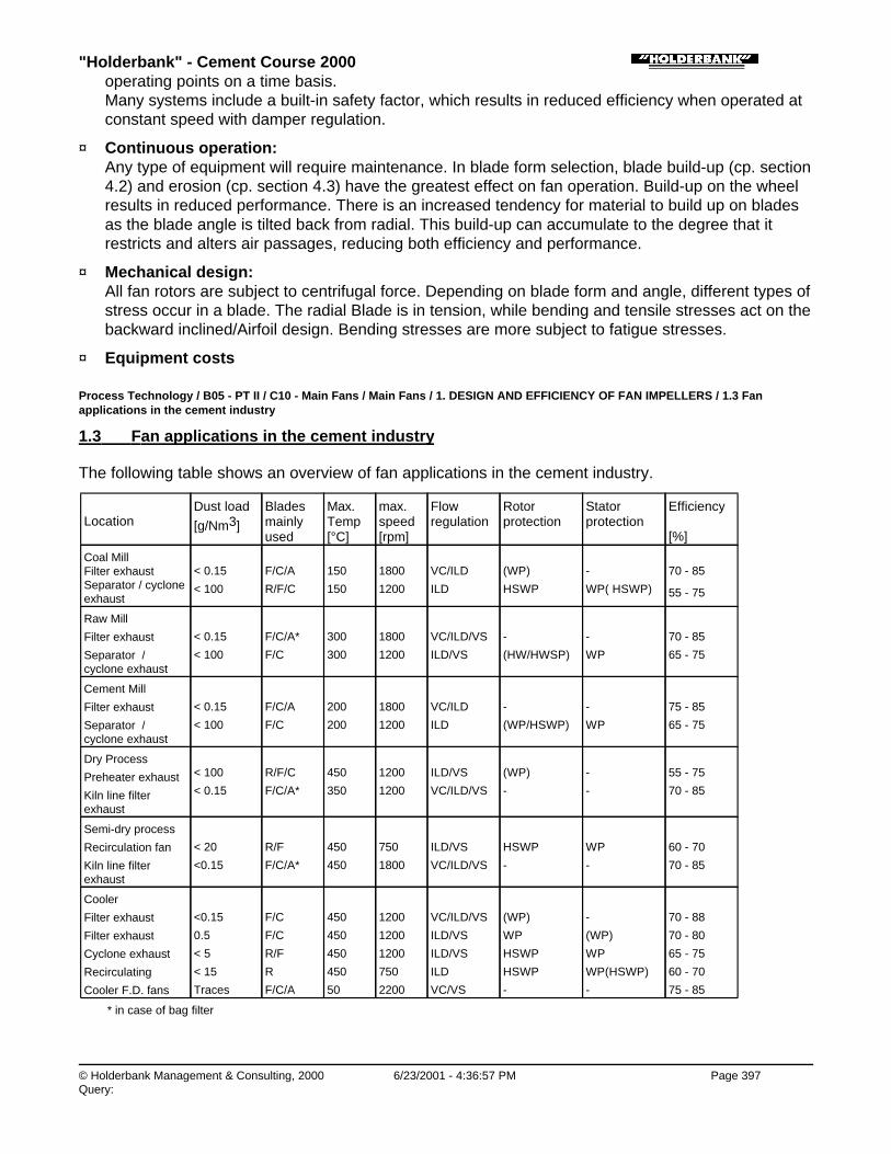
"Holderbank" - Cement Course 2000
© Holderbank Management & Consulting, 2000 6/23/2001 - 4:36:57 PM Page 397Query:
operating points on a time basis.Many systems include a built-in safety factor, which results in reduced efficiency when operated atconstant speed with damper regulation.
♦ Continuous operation:Any type of equipment will require maintenance. In blade form selection, blade build-up (cp. section4.2) and erosion (cp. section 4.3) have the greatest effect on fan operation. Build-up on the wheelresults in reduced performance. There is an increased tendency for material to build up on bladesas the blade angle is tilted back from radial. This build-up can accumulate to the degree that itrestricts and alters air passages, reducing both efficiency and performance.
♦ Mechanical design:All fan rotors are subject to centrifugal force. Depending on blade form and angle, different types ofstress occur in a blade. The radial Blade is in tension, while bending and tensile stresses act on thebackward inclined/Airfoil design. Bending stresses are more subject to fatigue stresses.
♦ Equipment costs
Process Technology / B05 - PT II / C10 - Main Fans / Main Fans / 1. DESIGN AND EFFICIENCY OF FAN IMPELLERS / 1.3 Fanapplications in the cement industry
1.3 Fan applications in the cement industry
The following table shows an overview of fan applications in the cement industry.
LocationDust load[g/Nm3]
Bladesmainlyused
Max.Temp[°C]
max.speed[rpm]
Flowregulation
Rotorprotection
Statorprotection
Efficiency
[%]
Coal Mill Filter exhaustSeparator / cycloneexhaust
< 0.15
< 100
F/C/A
R/F/C
150
150
1800
1200
VC/ILD
ILD
(WP)
HSWP
-
WP( HSWP)
70 - 85
55 - 75
Raw Mill
Filter exhaust
Separator /cyclone exhaust
< 0.15
< 100
F/C/A*
F/C
300
300
1800
1200
VC/ILD/VS
ILD/VS
-
(HW/HWSP)
-
WP
70 - 85
65 - 75
Cement Mill
Filter exhaust
Separator /cyclone exhaust
< 0.15
< 100
F/C/A
F/C
200
200
1800
1200
VC/ILD
ILD
-
(WP/HSWP)
-
WP
75 - 85
65 - 75
Dry Process
Preheater exhaust
Kiln line filterexhaust
< 100
< 0.15
R/F/C
F/C/A*
450
350
1200
1200
ILD/VS
VC/ILD/VS
(WP)
-
-
-
55 - 75
70 - 85
Semi-dry process
Recirculation fan
Kiln line filterexhaust
< 20
<0.15
R/F
F/C/A*
450
450
750
1800
ILD/VS
VC/ILD/VS
HSWP
-
WP
-
60 - 70
70 - 85
Cooler
Filter exhaust
Filter exhaust
Cyclone exhaust
Recirculating
Cooler F.D. fans
<0.15
0.5
< 5
< 15
Traces
F/C
F/C
R/F
R
F/C/A
450
450
450
450
50
1200
1200
1200
750
2200
VC/ILD/VS
ILD/VS
ILD/VS
ILD
VC/VS
(WP)
WP
HSWP
HSWP
-
-
(WP)
WP
WP(HSWP)
-
70 - 88
70 - 80
65 - 75
60 - 70
75 - 85
* in case of bag filter
"Holderbank" - Cement Course 2000
© Holderbank Management & Consulting, 2000 6/23/2001 - 4:36:58 PM Page 398Query:
Abbreviations:
a. Blade Type
R: radial blade
F: backward inclined flat plate
C: backward curved plate
A: backward airfoil blade
b. Flow regulation (cp. section 3)
VC: Vane control set at the fan inlet
ILD: Inlet louver damper set on the inlet box
VS: Variable speed
c. Rotor and stator protection against abrasion (cp. section 0)
WP: bolted or welded wear plates
- mild steel
- quenched steel
- wear-resistant steel
HSWP: bolted mild steel wear plates with hard surfacing
- chromium carbide
- tungsten carbide
(WP/HSWP): optional
Process Technology / B05 - PT II / C10 - Main Fans / Main Fans / 2. FAN PERFORMANCE CURVES
2. FAN PERFORMANCE CURVES
Process Technology / B05 - PT II / C10 - Main Fans / Main Fans / 2. FAN PERFORMANCE CURVES / 2.1 System Resistance Curve
2.1 System Resistance Curve
♦ The System Resistance Curve is the relation between pressure and volume flow for the givensystem. For a system in which only air is moved and the geometry of the ductwork is constant, thepressure drop is proportional to the square of the flow rate.
♦ In most of the applications around the cement plant, this curve is constantly changing because ofthe changing system conditions. For instance, the cooler under-grate fan system resistance curvedepends not only on the geometry of the ductwork and cooler, but also on size distribution andthickness of the clinker bed on the grate above the compartment.
♦ The system resistance curve of a roller mill system is dependent on the geometry of the ducts, theamount of material being transported by the gas, the composition of the gases and the speed ofthe classifier. Because of these variables, it is essential to understand that a system resistancecurve can vary significantly from the slope of the curve illustrated in e.g. Fig. 2.3.
♦ Principally the curve is derived as described next. Fig 2.1 schematically shows a system.
Fig. 2.1: System with fan

"Holderbank" - Cement Course 2000
© Holderbank Management & Consulting, 2000 6/23/2001 - 4:36:58 PM Page 399Query:
♦ Total pressure (dynamic and static part) at S: sssuc ppp ∆−= with ∆ps = pressure loss due to friction of the suction side
= ( )2Vf &
♦ Total pressure (dynamic and static part) at P:
pppress ppp ∆−= with ∆pp = pressure loss due to friction of the pressure side
= ( )2Vf &
♦ Pressure difference ∆pfan, which has to be produced by the fan,consists of a static and dynamic part and is a function of the gas velocity or gas flow.
∆p = ppress - psuc = = ∆pstat + ∆pdyn = f(w2) = ( )2Vf &
Process Technology / B05 - PT II / C10 - Main Fans / Main Fans / 2. FAN PERFORMANCE CURVES / 2.2 Fan curves
2.2 Fan curves
The fan performance curve is derived from laboratory data when the flow conditions to and from thefan are ideal. Since these conditions seldom exist in cement plant fan locations. The fan curve datacannot be considered reliable when applied to field conditions. Because of this uncertainty of theprevailing conditions, we find that engineers specify oversized fans during the plant design stage. For example, typical factors that can effect the performance of an under-grate cooler fan include a dirtyinlet screen; a structural column too close to the inlet; a silencer at fan inlet or the influence of anadjacent fan. Likewise, similar factors influencing an induced-draft fan include asymmetrical inlet ductwhich effects streamline distribution to the fan or heavier than normal blade wear pads that restrictblade passage geometry.
A typical fan curve (see Fig. 2.2) shows the quantity of air on the horizontal axis and the fan staticpressure and fan power plotted on the vertical axis. The conditions of density and flow are at the inletof the fan.
The actual operating point of the fan will be the intersection of the fan curve with the systemresistance curve (cp. section 2.1).
♦ The efficiency of a fan is best close to its design point of operation.The farther off these “ideal” conditions, the lower the efficiency. The operating points of equal fan
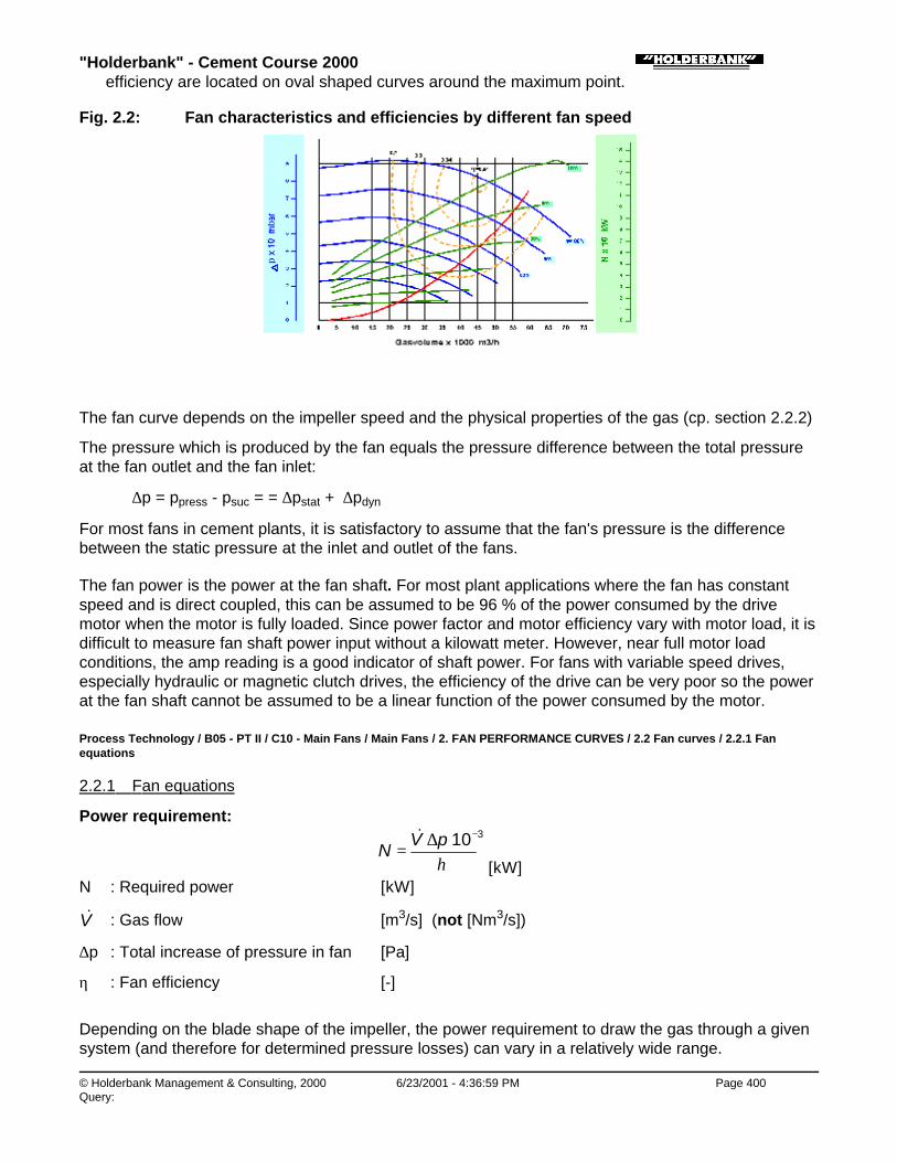
"Holderbank" - Cement Course 2000
© Holderbank Management & Consulting, 2000 6/23/2001 - 4:36:59 PM Page 400Query:
efficiency are located on oval shaped curves around the maximum point.
Fig. 2.2: Fan characteristics and efficiencies by different fan speed
The fan curve depends on the impeller speed and the physical properties of the gas (cp. section 2.2.2)
The pressure which is produced by the fan equals the pressure difference between the total pressureat the fan outlet and the fan inlet:
∆p = ppress - psuc = = ∆pstat + ∆pdyn
For most fans in cement plants, it is satisfactory to assume that the fan's pressure is the differencebetween the static pressure at the inlet and outlet of the fans.
The fan power is the power at the fan shaft. For most plant applications where the fan has constantspeed and is direct coupled, this can be assumed to be 96 % of the power consumed by the drivemotor when the motor is fully loaded. Since power factor and motor efficiency vary with motor load, it isdifficult to measure fan shaft power input without a kilowatt meter. However, near full motor loadconditions, the amp reading is a good indicator of shaft power. For fans with variable speed drives,especially hydraulic or magnetic clutch drives, the efficiency of the drive can be very poor so the powerat the fan shaft cannot be assumed to be a linear function of the power consumed by the motor.
Process Technology / B05 - PT II / C10 - Main Fans / Main Fans / 2. FAN PERFORMANCE CURVES / 2.2 Fan curves / 2.2.1 Fanequations
2.2.1 Fan equations
Power requirement:
η
310−∆=
pVN
&
[kW]N : Required power [kW]
V& : Gas flow [m3/s] (not [Nm3/s])
∆p : Total increase of pressure in fan [Pa]
η : Fan efficiency [-]
Depending on the blade shape of the impeller, the power requirement to draw the gas through a givensystem (and therefore for determined pressure losses) can vary in a relatively wide range.

"Holderbank" - Cement Course 2000
© Holderbank Management & Consulting, 2000 6/23/2001 - 4:37:00 PM Page 401Query:
As the required fan power is given by the equation above, it is obvious that considerable savings canbe achieved with the most efficient impeller.
Total pressure increase:
Formula for a rough calculation of the total pressure ∆p = ppress - psuc = ∆pstat + ∆pdyn:
∆p ≈ 36006.0 222 πρ dn
[Pa]ρ : Density [kg/m3]
n : Fan speed [rpm]
d : Impeller diameter [m]
Remark: ∆p is just a rough guideline and depends very much on the blades shape and the rotorefficiency.
Example: Effect of fan efficiency
Plant: 4-stage SP kiln, 3000 t/d clinker
Requirement for kiln ID-fan: V& = 115 m3/s at 350°C∆p = 6000 PaÙ two efficiencies available: η1 = 0.75 η2 = 0.85
kWpV
N 92075.0
10600011510 3
1
3
1 =⋅⋅
=∆
=−−
η
&
kWpV
N 81285.0
10600011510 3
2
3
2 =⋅⋅
=∆
=−−
η
&
Power saving = 108 kW = 0.86 kWh/t cli
Assuming an operation time of 7500 h/year and an energy price of 0.05 US$/kWh theyearly saving will amount to 40’500 US$!
Process Technology / B05 - PT II / C10 - Main Fans / Main Fans / 2. FAN PERFORMANCE CURVES / 2.2 Fan curves / 2.2.2 Adjustingfan performance curves
2.2.2 Adjusting fan performance curves
It was mentioned above that the fan performance curve is given at specific conditions of density andfan speed. Most often, it is necessary to correct the fan curve for density and speed other than thepredicted conditions. Fig. 2.3 shows the influence of density changes on the fan performance.
Indices: 1: reference conditions (or original fan curve characteristic) 2: actual conditions
Gas density correction:
"Holderbank" - Cement Course 2000
© Holderbank Management & Consulting, 2000 6/23/2001 - 4:37:00 PM Page 402Query:
A correction of the density is necessary if:
♦ temperature changes
♦ the chemical composition of gas changes
♦ the altitude changes (height above sea level).
1
2
2
1
2
1
TT
pp
stat
stat ==ρρ
Volume flow and efficiency of the fan are unaffected by gas density changes.
Remark: À Calculation of actual density
273273
10134.22 +⋅⋅=T
pMρ
ρ density [kg/m3]
M molecular weight of gas [kg/kmol]
p actual pressure [mbar]
T actual temperature [°C]
Á Ambient pressure, depending on the altitudes can be calculated by:[ ]h001255.0exp1013p ⋅−⋅=
h altitude above sea level [m]
GasDensity [kg/Nm3]
Molecular weight[kg/kmol]
O2 1.429 32
CO2 1.964 44
N2 1.250 28
Air 1.292 29
H2O 0.804 18
Fan speed correction:
Volume flow:
⋅=
1
212 n
nVV &&

"Holderbank" - Cement Course 2000
© Holderbank Management & Consulting, 2000 6/23/2001 - 4:37:01 PM Page 403Query:
Static pressure:
2
1
212
⋅=
nn
pp statstat
Power requirement:
3
1
212
⋅=
nn
NN
(for η1 = η2)
Fan wheel dimensions correction:
Volume flow:
⋅
⋅=
1
2
3
1
212 b
bdd
VV &&
Static pressure:
2
1
212
⋅=
dd
pp statstat
Power requirement:
⋅
⋅=
1
2
5
1
212 b
bdd
NN
whereas d impeller diameter [m]b impeller width [m]
Fig. 2.3: Influence of density changes on system resistance and fan performance curves
Process Technology / B05 - PT II / C10 - Main Fans / Main Fans / 3. FLOW CONTROL
3. FLOW CONTROL
Whether a fan ever will operate at a high efficiency is to a large extent already decided when the fansize is selected.
Since the efficiency of the fan has a maximum at a specific operating point the fan ought to be sized sothat it can operate at such conditions most of the time. However, since the fan performance needs to

"Holderbank" - Cement Course 2000
© Holderbank Management & Consulting, 2000 6/23/2001 - 4:37:02 PM Page 404Query:
be flexible to meet variable requirements, the fan size will, to some extent at least, be designed for themaximum requirement. Reduced requirements have to be met by fan control dampers or variablespeed control.
Besides the efficiency of the fan itself, the type of flow control has the strongest influence on the overallpower consumption.
Damper control generally results in higher power consumption and so more if the damper is installed atthe fan outlet. Therefore the damper should always be installed at fan inlet. Inlet vane control may besatisfactory from 100 % down to about 70 % of maximum flow, but the power demand becomes highwhen the flow is reduced further. Speed control is virtually ideal.
Fig 3.1 shows different arrangements for inlet and outlet dampers.
Fig. 3.1: Design possibilities for fan dampers
Figure 3.2 shows how fan power consumption is affected by the different flow regulation methods.
Fig. 3.2: Comparison: Types of Flow Regulation
Process Technology / B05 - PT II / C10 - Main Fans / Main Fans / 3. FLOW CONTROL / 3.1 Damper control

"Holderbank" - Cement Course 2000
© Holderbank Management & Consulting, 2000 6/23/2001 - 4:37:04 PM Page 405Query:
3.1 Damper control
A parallel blade inlet damper is preferred over either outlet damper or an opposed-blade inlet damper.The parallel-blade inlet damper pre-spins the incoming air in the direction of wheel rotation, resulting inlower energy consumption in the regulation range of 100 - 80% of maximum flow. Fig. 3.3 shows theparallel inlet damper arrangement.
Fig. 3.3: Parallel inlet box damper
The inlet box damper influences the fan curve (see Fig. 3.4).
Fig. 3.4: Flow regulation by inlet box damper
Fig. 3.5 shows the operating point at the intersection of the system resistance curve and the fan curve.By reducing the airflow, the fan theoretically produces a pressure above 80 mbar. Since the systembehaves like the system resistance curve, the damper induces a pressure loss of about 40 mbar.
Fig. 3.5: Flow regulation by outlet damper

"Holderbank" - Cement Course 2000
© Holderbank Management & Consulting, 2000 6/23/2001 - 4:37:04 PM Page 406Query:
Process Technology / B05 - PT II / C10 - Main Fans / Main Fans / 3. FLOW CONTROL / 3.2 Radial inlet vane
3.2 Radial inlet vane
The radial inlet vane mounted direct at the fan inlet pre-spins the incoming air still better in the directionof wheel rotation, resulting in a wider range of stable regulation (100 - 70%) and less energyconsumption. Fig. 3.6 shows the parallel inlet damper arrangement.
Fig 3.6: Radial inlet vane
Their use is mainly recommended in connection with over hung arrangement fans with low rates ofdust, thus limited to applications after filters or in clean air, e.g. for cooler under-grate fans.
This arrangement is normally more costly.
Fig. 3.7: Flow regulation by inlet vane damper

"Holderbank" - Cement Course 2000
© Holderbank Management & Consulting, 2000 6/23/2001 - 4:37:05 PM Page 407Query:
Process Technology / B05 - PT II / C10 - Main Fans / Main Fans / 3. FLOW CONTROL / 3.3 Speed control
3.3 Speed control
Variable speed controlled fans have more fan characteristic curves but only one characteristic curve ofthe duct system (see Fig. 3.8).
It is obvious that the variable speed drive is the most efficient type of fan control since no additionalresistance for e.g. damper is built into the system. On the other hand a variable speed control is morecapital intensive than a damper control.
Fig. 3.8: Flow regulation by speed control
Process Technology / B05 - PT II / C10 - Main Fans / Main Fans / 3. FLOW CONTROL / 3.3 Speed control / 3.3.1 Hydraulictransmission with fixed speed motor
3.3.1 Hydraulic transmission with fixed speed motor
Hydraulic transmission in connection with a fixed speed motor can be an option for speed ranges from100% down to 85% of maximum speed, but the energy efficiency becomes low when the flow is furtherreduced.
Process Technology / B05 - PT II / C10 - Main Fans / Main Fans / 3. FLOW CONTROL / 3.3 Speed control / 3.3.2 Speed-controlledelectric motors

"Holderbank" - Cement Course 2000
© Holderbank Management & Consulting, 2000 6/23/2001 - 4:37:05 PM Page 408Query:
3.3.2 Speed-controlled electric motors
Flow control by variation of the fan speed is most efficient with regard to energy savings and permitsalso the reduction of wear on the fan wheel.
♦ DC motors have limitations in high speed and power (roughly 1000 rpm for 1500 kW, 600 to 800rpm for 2000 kW motor) and require a lot of maintenance work (motor ventilation circuits, carbonbrushes etc.), so their use is not recommended any longer.
♦ AC motors with slip recovery. These motors have a limited speed range down from 100 - 30%. Itscost increases with the width of the range.
♦ Synchronous motors with AC variable frequency control
Both types of AC motors are well suited for high power (500 to 5000 kW).
Fan equations at variable speed:
Volume flow:
⋅=
1
212 n
nVV &&
Static pressure:
2
1
212
⋅=
nn
pp statstat
Power requirement:
3
1
212
⋅=
nn
NN
(for η1 = η2)
Process Technology / B05 - PT II / C10 - Main Fans / Main Fans / 4. POSSIBLE PROBLEMS WITH FANS
4. POSSIBLE PROBLEMS WITH FANS
Process Technology / B05 - PT II / C10 - Main Fans / Main Fans / 4. POSSIBLE PROBLEMS WITH FANS / 4.1 Vibrations
4.1 Vibrations
Main reasons for fan vibrations are build-ups of process material (refer to section 4.2) andwear/erosion on the fan impeller (refer to section 4.3/0). A moderate level of vibration can be toleratedfrom a mechanical design point of view, although it certainly reduces the bearing lifetime to a certainextent. Therefore it should be tolerated only to avoid additional main equipment downtime.
If vibrations are excessive, fan impeller balancing, cleaning or replacement is required. For balancingspecial vibration detectors are used on site or the wheel has to be shop balanced.
General Machinery vibration severity as per ANSI S2.41 (Fig. 4.1 a) for use as a guide in judgingvibration as a warning of impending trouble)
1. Rigid supportThe fundamental natural frequency of the machine/support system is higherthan the operating speed

"Holderbank" - Cement Course 2000
© Holderbank Management & Consulting, 2000 6/23/2001 - 4:37:06 PM Page 409Query:
than the operating speed
excellent 0. to 2.54 mm/s vibration velocity (Peak)
good 2.55 to 6.35 mm/s
alarm 6.36 to 12.7 mm/s
shutdown > 12.7 mm/s
2. Flexible supportThe fundamental natural frequency of the machine/support system is lowerthan the operating speed
excellent 0. to 3.81 mm/s vibration velocity (Peak)
good 3.81 to 10.16 mm/s
alarm 10.17 to 19.1 mm/s
shutdown > 19.1 mm/s
Vibration severity criteria (10 Hz to 1 kHz) per ISO 2372 (Fig. 4.1 b)
1. Large machines with rigid foundations whose natural frequency exceedsmachine speed
good 0.0 to 2.54 mm/s vibration velocity (Peak)
allowable 2.55 to 6.35 mm/s
just tolerable 6.36 to 15.84 mm/s
not permissible > 15.84 mm/s
2. Large machines operating at speeds above foundation natural frequency
good 0 to 4 mm/s vibration velocity (Peak)
allowable 4 to 10 mm/s
just tolerable 10 to 25.4 mm/s
not permissible > 25.4 mm/s
If the tolerable vibration levels are exceeded, the fan must be shut down, which usually results in costlyproduction losses. To extend the periods between shutdowns due to vibration, the use of automaticbalancing devices, mounted on the fan shaft may be considered. Depending on their size, they arecapable of automatic compensation of a certain rotor unbalance. For manufacturers of such devices,refer to the information source at the end of this report.
Fig. 4.1 a: Vibration severity chart (ANSI S2.41)

"Holderbank" - Cement Course 2000
© Holderbank Management & Consulting, 2000 6/23/2001 - 4:37:06 PM Page 410Query:
Fig. 4.1 b: Vibration severity chart (ISO 2372)
Process Technology / B05 - PT II / C10 - Main Fans / Main Fans / 4. POSSIBLE PROBLEMS WITH FANS / 4.1 Vibrations / 4.1.1Variable speed operation
4.1.1 Variable speed operation
All electrical variable speed drive systems can generate harmful harmonics that result in torquepulsation. Such harmonics can be predicted and filtered, but often at high cost. For fans with variablespeed control it must be verified by the motor supplier that the pulsating torque do not cause excessivevibrations.
Process Technology / B05 - PT II / C10 - Main Fans / Main Fans / 4. POSSIBLE PROBLEMS WITH FANS / 4.1 Vibrations / 4.1.2Thermal effects
4.1.2 Thermal effects
Some typical problem areas are:
♦ Due to expansion joint problems, forces due to thermal expansion of ducts are transmitted to thefan housing, resulting in damage of the housing or interference between wheel and housing. It canalso cause excessive force on foundation bolts that sometimes can result in foundation cracks.
♦ Rapid temperature changes in a system require proper design of the wheel-to-shaft fit. This willassure that looseness and resulting vibration sensitivity will be avoided.

"Holderbank" - Cement Course 2000
© Holderbank Management & Consulting, 2000 6/23/2001 - 4:37:07 PM Page 411Query:
Process Technology / B05 - PT II / C10 - Main Fans / Main Fans / 4. POSSIBLE PROBLEMS WITH FANS / 4.1 Vibrations / 4.1.3 Hotshutdowns
4.1.3 Hot shutdowns
Thermal shaft set is a usual concern on centre-hung fans above 120°C when shut down in the hotcondition. It is generally agreed that this thermal bowing of the shaft occurs due to uneven thermalgradients across the wheel and shaft assembly at hot shutdown. This results in small asymmetricaldistortions, often sufficient to cause excessive unbalance forces during start-up.
In some cases the resulting vibrations are within acceptable limits. If so, it is usually found that theunbalance forces disappear after 12 to 36 hours of operation.
The preferred, but expensive solution is to have an auxiliary drive to slowly rotate the wheel and shaftassembly, which should be engaged immediately after hot shut-down to avoid the undesirable thermaldistortion. Auxiliary drives are typically designed to maintain a minimum speed (40 to 60 rpm) as thefan slows down. They are not intended for use in starting the fan rotor from a dead stop.
Most hot gas fans work well without auxiliary drive, since hot shutdowns are infrequent and of shortduration and the natural draft of the chimney keeps the rotor in slow motion for some time.
The tendency is to install hot gas fans without auxiliary drives. Often it is also the case that variablespeed drives have a turndown ratio of 10:1, which corresponds normally to less than 70 rpm.
Process Technology / B05 - PT II / C10 - Main Fans / Main Fans / 4. POSSIBLE PROBLEMS WITH FANS / 4.2 Material build-up
4.2 Material build-up
A well maintained fan is generally a reliable piece of equipment. However, in case of material build-upswithin the fan, serious operational limitations could occur, such as vibrations.
Possible reasons for material build-ups are:
• Mineralogical composition of the material
• Burning conditions
• Duct/fan arrangement
• High temperatures
• Inappropriate blade shape and angles
• High fan speed
• Dew point problems
After balancing, the rotor of a fan will still have a certain residual imbalance, the value of whichdepends on the balance quality grade. The unbalance force can be calculated with the formula:
peremF ⋅⋅= 2ω [N]
m rotor mass [kg]ω angular velocity 2πn/60 [s-1]n rotor speed [rpm]eper permissible residual specific unbalance [m]
Industrial fans often handle dust-laden gases and thus dust deposition on the impeller may occur,increasing the initial unbalance. Asymmetrical wear on the impeller has the same effect. These

"Holderbank" - Cement Course 2000
© Holderbank Management & Consulting, 2000 6/23/2001 - 4:37:07 PM Page 412Query:
additional unbalances can be considerable compared to the permissible unbalance according to thebalance quality grade. If the resulting vibration exceeds the tolerable limits, the fan has to be shut downto clean the wheel. See Fig. 4.1 c for permissible unbalance.
Fig. 4.1 c: Balance quality grades
Process Technology / B05 - PT II / C10 - Main Fans / Main Fans / 4. POSSIBLE PROBLEMS WITH FANS / 4.2 Material build-up / 4.2.1Kiln exhaust fan build-up
4.2.1 Kiln exhaust fan build-up
One idea about the causes of build-up is that some particles are "sticky" at temperatures above 300°Cand begin to build up on the rotor surfaces. The impact energy of the particles striking the rotor surface(especially at an angle of 90°) is also converted to heat and results in additional softening. Otherparticles with a higher softening point are caught in the sticky material and increase the coating layerthickness. The originally soft build-up gets harder under the influence of heat and pressure (fromcentrifugal force and the impact of other particles).
Process Technology / B05 - PT II / C10 - Main Fans / Main Fans / 4. POSSIBLE PROBLEMS WITH FANS / 4.2 Material build-up / 4.2.2Recommendations against build-up
4.2.2 Recommendations against build-up
♦ The fan rotor should be designed for the smoothest possible flow lines to reduce the impact energyof dust particles. Backward curved and airfoil are the best blade forms. Airfoil blades must bedesigned carefully to prevent material from getting inside and regular inspection of the fan blades ismandatory.Backward curved blades must be inclined enough to prevent the "hard" build-up on the frontsurface and radial enough to prevent the "soft" build-up on the back-surface.
♦ Fans should be designed for low gas and particle velocity at the fan inlet. This reduces the impactenergy of particles against the rotor and can be achieved by
1) Double inlet instead of single inlet fans
2) Larger diameter / lower speed fans
3) If possible, the peripheral speed at the rotor inlet opening should be limited to about 76 m/s,and wheel inlet velocity should not exceed 38 m/s
4) The fan shaft should be oversized to reduce unbalance effects.
The design critical speed (considering a bearing oil film thickness and a build-up thickness of 25 mmon all leading surfaces of the rotor blades) should be at least 1.25 times the operating speed of the fan.
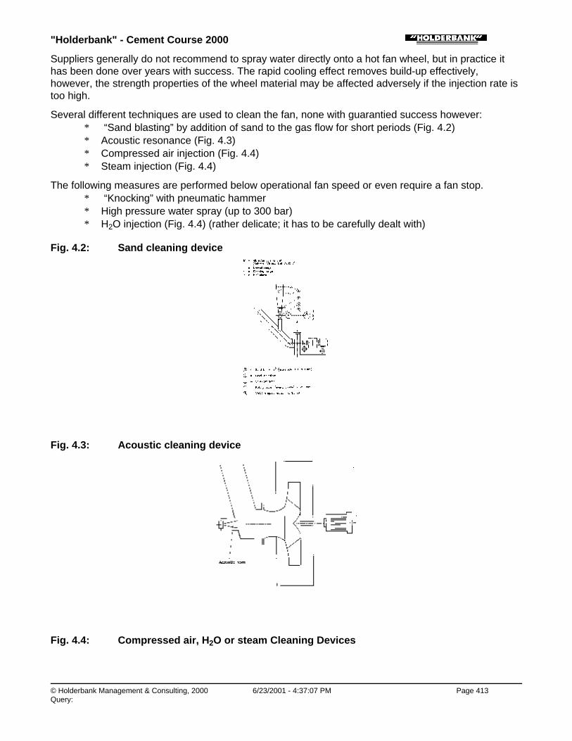
"Holderbank" - Cement Course 2000
© Holderbank Management & Consulting, 2000 6/23/2001 - 4:37:07 PM Page 413Query:
Suppliers generally do not recommend to spray water directly onto a hot fan wheel, but in practice ithas been done over years with success. The rapid cooling effect removes build-up effectively,however, the strength properties of the wheel material may be affected adversely if the injection rate istoo high.
Several different techniques are used to clean the fan, none with guarantied success however:∗ “Sand blasting” by addition of sand to the gas flow for short periods (Fig. 4.2)∗ Acoustic resonance (Fig. 4.3)∗ Compressed air injection (Fig. 4.4)∗ Steam injection (Fig. 4.4)
The following measures are performed below operational fan speed or even require a fan stop.∗ “Knocking” with pneumatic hammer∗ High pressure water spray (up to 300 bar)∗ H2O injection (Fig. 4.4) (rather delicate; it has to be carefully dealt with)
Fig. 4.2: Sand cleaning device
Fig. 4.3: Acoustic cleaning device
Fig. 4.4: Compressed air, H2O or steam Cleaning Devices

"Holderbank" - Cement Course 2000
© Holderbank Management & Consulting, 2000 6/23/2001 - 4:37:08 PM Page 414Query:
Process Technology / B05 - PT II / C10 - Main Fans / Main Fans / 4. POSSIBLE PROBLEMS WITH FANS / 4.3 Erosion
4.3 Erosion
Process Technology / B05 - PT II / C10 - Main Fans / Main Fans / 4. POSSIBLE PROBLEMS WITH FANS / 4.3 Erosion / 4.3.1 Erosiontypes
4.3.1 Erosion types
It has been established that maximum erosion occurs when the angle of incidence between particleand surface is between 20 and 40 degrees. This erosion, referred to as "ductile", is thought to be theconsequence of microscopic melting, which occurs when sharp-edged, hard particles scratch thesurface.
Particles striking at an angle of about 90 degrees to the surface erode according to anothermechanism. The kinetic energy of the particle creates a stress at the contact surface that can exceedthe elastic limit of the material, thus forming a surface crack. This type of erosion is called "fragile".
Process Technology / B05 - PT II / C10 - Main Fans / Main Fans / 4. POSSIBLE PROBLEMS WITH FANS / 4.3 Erosion / 4.3.2 Improperduct connection
4.3.2 Improper duct connection
Figure 4.5a shows a duct arrangement encountered on a raw mill system. Due to the uneven materialdistribution one side of the double-inlet impeller wore out much faster.
Figure 4.5b shows the recommended modification.
Fig. 4.5a, Fig. 4.5b
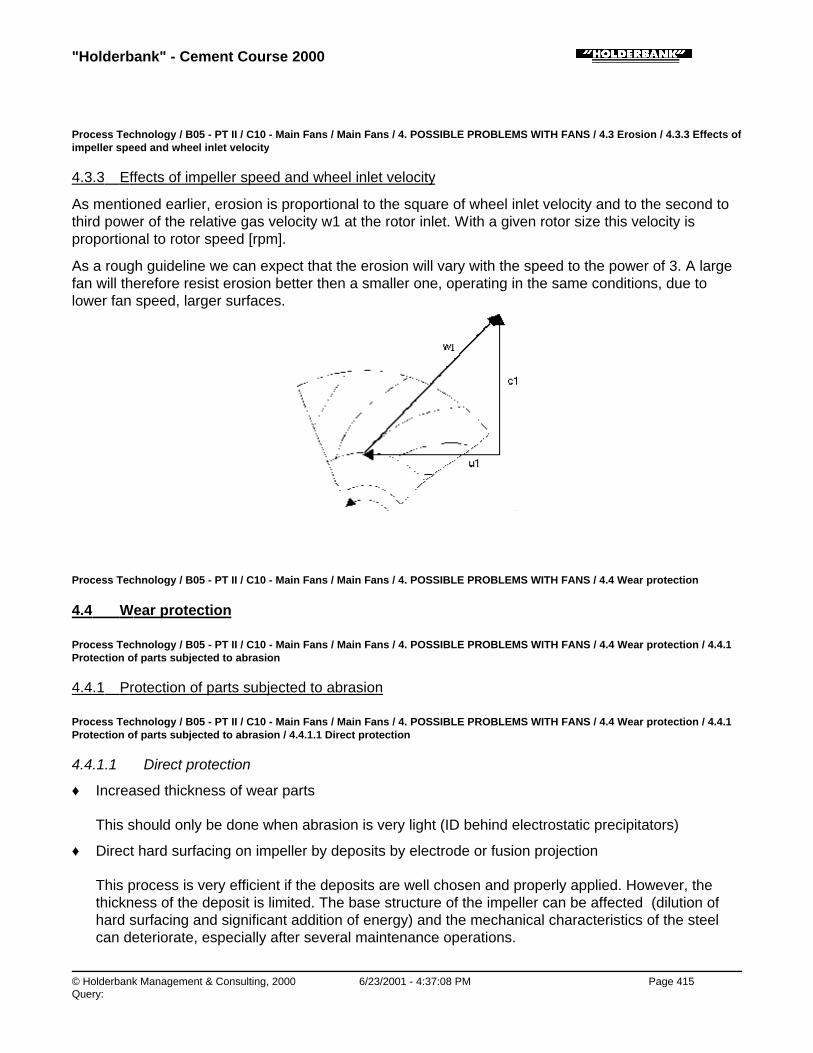
"Holderbank" - Cement Course 2000
© Holderbank Management & Consulting, 2000 6/23/2001 - 4:37:08 PM Page 415Query:
Process Technology / B05 - PT II / C10 - Main Fans / Main Fans / 4. POSSIBLE PROBLEMS WITH FANS / 4.3 Erosion / 4.3.3 Effects ofimpeller speed and wheel inlet velocity
4.3.3 Effects of impeller speed and wheel inlet velocity
As mentioned earlier, erosion is proportional to the square of wheel inlet velocity and to the second tothird power of the relative gas velocity w1 at the rotor inlet. With a given rotor size this velocity isproportional to rotor speed [rpm].
As a rough guideline we can expect that the erosion will vary with the speed to the power of 3. A largefan will therefore resist erosion better then a smaller one, operating in the same conditions, due tolower fan speed, larger surfaces.
Process Technology / B05 - PT II / C10 - Main Fans / Main Fans / 4. POSSIBLE PROBLEMS WITH FANS / 4.4 Wear protection
4.4 Wear protection
Process Technology / B05 - PT II / C10 - Main Fans / Main Fans / 4. POSSIBLE PROBLEMS WITH FANS / 4.4 Wear protection / 4.4.1Protection of parts subjected to abrasion
4.4.1 Protection of parts subjected to abrasion
Process Technology / B05 - PT II / C10 - Main Fans / Main Fans / 4. POSSIBLE PROBLEMS WITH FANS / 4.4 Wear protection / 4.4.1Protection of parts subjected to abrasion / 4.4.1.1 Direct protection
4.4.1.1 Direct protection
♦ Increased thickness of wear parts
This should only be done when abrasion is very light (ID behind electrostatic precipitators)
♦ Direct hard surfacing on impeller by deposits by electrode or fusion projection
This process is very efficient if the deposits are well chosen and properly applied. However, thethickness of the deposit is limited. The base structure of the impeller can be affected (dilution ofhard surfacing and significant addition of energy) and the mechanical characteristics of the steelcan deteriorate, especially after several maintenance operations.

"Holderbank" - Cement Course 2000
© Holderbank Management & Consulting, 2000 6/23/2001 - 4:37:09 PM Page 416Query:
♦ Glued-on ceramics
Their hardness is very high and they are very resistant to ductile abrasion
Temperature must be limited and the ceramics tend to come off at the blade end (high centrifugalforces). Application on static parts is easier and more reliable.
Process Technology / B05 - PT II / C10 - Main Fans / Main Fans / 4. POSSIBLE PROBLEMS WITH FANS / 4.4 Wear protection / 4.4.1Protection of parts subjected to abrasion / 4.4.1.2 Protection by wear plates
4.4.1.2 Protection by wear plates
♦ Corners or mild steel plates (or steel of the same grade as the base structure) added on to theblade and on the center plate. This protection is applicable only where abrasion is low. If theprotection area is not wide enough, the base plate can also be attacked.
♦ Wear-plates in abrasion resistant steel. This process is applied particularly on flat-bladed impellers.The wear-plates are fitted on with countersunk screws. Replacement is easy, but the solution canbe insufficient if abrasion is very high.
♦ Mild steel wear plates with hard surfacing by electrode or hardsurface spray coating. This solutionhas the double advantage of easy replacement and high resistance to abrasion when the type ofdeposit is well chosen. Moreover, hard surfacing on site is easily carried out with no risk for thebase structure.
Process Technology / B05 - PT II / C10 - Main Fans / Main Fans / 4. POSSIBLE PROBLEMS WITH FANS / 4.4 Wear protection / 4.4.2Deflection of abrasive particles
4.4.2 Deflection of abrasive particles
Process Technology / B05 - PT II / C10 - Main Fans / Main Fans / 4. POSSIBLE PROBLEMS WITH FANS / 4.4 Wear protection / 4.4.2Deflection of abrasive particles / 4.4.2.1 Deflector plates on impeller (Fig. 4.6)
4.4.2.1 Deflector plates on impeller (Fig. 4.6)
Fig. 4.6a shows the fan inlet and the rotating impeller. A, B and C are flow lines for the gas and lines 1,2 and 3 represent the trajectories for particles of varying size. Line 1 refers to a very small particle thatclosely follows the gas flow line. With increasing particle size the trajectories 2 and 3 deviate from thegas flow lines. The particles hit the back-plate of the impeller and erode it.
Fig. 4.6b depicts the passage of two different particle sizes between two blades. Line 1 is thetrajectory of a small particle, line 2 of a coarser one. Most particles will hit the blade during theirpassage through the impeller.
With suitably located deflector plates (Fig. 4.6c), the particle trajectories can be altered so that noparticles will hit the blades. The location and direction of the deflectors depends on the particle sizedistribution, density of gas and particle, and fan speed and size.
Fig. 4.6: Wear protection by particle deflection

"Holderbank" - Cement Course 2000
© Holderbank Management & Consulting, 2000 6/23/2001 - 4:37:09 PM Page 417Query:
Process Technology / B05 - PT II / C10 - Main Fans / Main Fans / 4. POSSIBLE PROBLEMS WITH FANS / 4.4 Wear protection / 4.4.3Liner materials
4.4.3 Liner materials
Due to the need for ductility in the structural members of the wheel, the wheel itself is usually notcapable of high resistance to erosion. It is therefore necessary to install liners with a higher hardnessclassification to provide sufficient protection against wear.
Material hardness is an indication of its resistance to erosion. A very good liner material is chromiumcarbide with an average hardness of 600 Brinell.
Figure 4.7 shows erosion test results of nine different materials.
Fig. 4.7: Erosion Test on Fan (Solyvent-Ventec)
1) Alloy of tungsten and nickel-chromium. Flame spray coating.
2) Alloy of nickel, chromium and cobalt. Flame spray coating followed by fusion.
3) Alloy of tungsten, cobalt carbides and nickel-chromium. Flame spray coating followed by fusion.
4) Special chromium cast iron. Special electric arc welding.
5) Chromium cast iron with chromium carbides. Electric arc welding.
6) Chromium cast iron. Semi-automatic electric arc welding.
7) Ceramic powder containing basically aluminium oxide. Flame spray coating.

"Holderbank" - Cement Course 2000
© Holderbank Management & Consulting, 2000 6/23/2001 - 4:37:09 PM Page 418Query:
8) Same as 7, but of different hardness.
9) Ceramic tiles containing basically aluminium oxide. Glued to the blades.
Carbon steel sheets with a protective layer of chromium carbide are normally available in standardsizes and various thicknesses. Cutting discs or cutting plasma can cut them to the necessary form andsize.
The liner fixation can be done by bolting or by welding the carbon steel base plate to the existingstructure of the wheel or casing.
Process Technology / B05 - PT II / C10 - Main Fans / Main Fans / 4. POSSIBLE PROBLEMS WITH FANS / 4.5 Bearings
4.5 Bearings
Bearing problems are usually caused by operating conditions and not by deficiencies in the bearings.By following regular operating and maintenance procedures, many bearing problems will be avoided. Most problems are due to hot bearings. For hints see section 5.
Process Technology / B05 - PT II / C10 - Main Fans / Main Fans / 5. FAN CAPACITY ADJUSTMENT
5. FAN CAPACITY ADJUSTMENT
Fan capacity adjustments in the field are practically limited to the speed adjustment and this within alimited range: ~ 0 - 15 % for flow increase and ~ 0 - 30 % for flow reduction.
Other capacity adjustments require mainly dimensional modifications of the fan wheel, which have tobe carried out in the workshop. Those are more costly and critical to execute.
Process Technology / B05 - PT II / C10 - Main Fans / Main Fans / 5. FAN CAPACITY ADJUSTMENT / 5.1 Fan capacity too low
5.1 Fan capacity too low
Important variables that are hampered by insufficient gas flow are e.g.
♦ kiln production
♦ separator efficiency
♦ mill performance (throughput, drying capacity, mill venting)
Possible remedies:
♦ Design changes in the system (reduce false air, reduce pressure drop)the fan consumes no additional energy!
♦ reduce/rectify false air inleaks
♦ reduce unnecessary pressure drops caused by e.g.
• not fully open dampers
• improper design of inlet/outlet connections
• no turning vanes in bends (refer to section 8.3)
• dust deposits in ducts and bends
• too narrow ducts (appropriate air speed must however be maintained to avoid settling of dust)
♦ Changes in fan design, speed

"Holderbank" - Cement Course 2000
© Holderbank Management & Consulting, 2000 6/23/2001 - 4:37:10 PM Page 419Query:
• Speed increase∗ volume flow is directly proportional to fan speed∗ fan absorbed power rises with the third power of fan speed∗ fan works with lower than design efficiency ∗ normally only possible with V-belt drives∗ sound emission rises with fifth power of speed∗ higher wear, if fan handles dust-laden gas∗ increased sensitivity to rotor imbalance caused by dust deposits on blades∗ speed increase is limited by mechanical strength of rotor∗ speed increase is limited by fan critical and resonant speed
• Fan wheel diameter increase∗ practically limited to wheels where the blades do not extend to the full diameter of the rotor
sideplates (plates can then be welded-in to increase the effective fan wheel diameter)∗ volume flow rises with the third power of wheel diameter∗ fan absorbed power rises with the fifth power of wheel diameter
• Replacement of rotor with inherent low efficiency by one designed for high efficiency∗ e.g. replacement of radial-blade wheel by backward-inclined or backward-curved blade
wheel.∗ limitations with regard to diameter, width (and speed, if wheel is directly coupled to motor
via flexible coupling) of the new wheel exist if fan housing and motor are to be kept.
♦ New fanCan be designed for optimum performance at the new operating point
Process Technology / B05 - PT II / C10 - Main Fans / Main Fans / 5. FAN CAPACITY ADJUSTMENT / 5.2 Fan capacity too high
5.2 Fan capacity too high
May be due to e.g. oversized fan, decline in production, process changes
Possible remedies:
♦ Flow reduction by damperWidely used solution, but inefficient and expensive (fan energy consumption)
♦ Flow reduction by inlet vane damperMore energy-efficient than damper, but can be recommended only for flow regulation purposes, notfor permanent use at lower capacity (expensive, may be difficult to fit into existing equipment)
♦ Changes in fan design, speed
• Lower speed ∗ volume flow decreases proportional to fan speed∗ absorbed power decreases with third power of fan speed∗ lower sound emission∗ lower wear, if handling dust-laden gas∗ lower sensitivity to rotor imbalance caused by e.g. dust deposits on blades
• Rotor width reduction∗ applicable if fan must deliver the same pressure as before, but at lower volume flow
• Rotor diameter / width reduction∗ volume flow decreases with the third power of rotor diameter∗ volume flow decreases proportional to rotor width

"Holderbank" - Cement Course 2000
© Holderbank Management & Consulting, 2000 6/23/2001 - 4:37:10 PM Page 420Query:
∗ fan delivery pressure decreases with the square of rotor diameter∗ absorbed power decreases with the fifth power of rotor diameter∗ absorbed power decreases proportional to width∗ lower sound emission
• To maintain a good efficiency, it is not sufficient to decrease the diameter only, but alsoto adapt the rotor width.For a permanent capacity reduction this is a good solution
If the old transmission is kept, speed reduction is normally reversible, i.e. fan capacity can beincreased again if necessary, whereas a reduction in rotor diameter / width are not.
Process Technology / B05 - PT II / C10 - Main Fans / Main Fans / 6. TROUBLESHOOTING
6. TROUBLESHOOTING
Problem Check for
Noise 1. Squealing V-belts, due to misalignment or improper tensioning 2. Defective bearings, or bearing seal rubbing 3. Misalignment of bearing seal 4. Misaligned housing-shaft seal 5. Foreign matter in fan housing 6. Rubbing of shaft seal, wheel to inlet piece, or wheel to housing 7. Heat flinger is contacting guard 8. Coupling failure 9. Untreated expansion joints
Poorperformance
1. Incorrect fan rotation 2. Wheel is off-center, poor inlet piece fit-up allows recirculation of air 3. Fan speed too low/high 4. Poor duct design, installation of elbow or turning vanes could
remedy problem 5. Inlet damper installed backwards (counter-rotation) 6. System resistance is excessive compared to design requirements
(partially closed damper may be the cause) 7. Density may be different from design density

"Holderbank" - Cement Course 2000
© Holderbank Management & Consulting, 2000 6/23/2001 - 4:37:11 PM Page 421Query:
Problem Check for
High bearingtemperature
1. Defective bearings caused by electrical arc due to impropergrounding of nearby welding
2. Over-lubrication 3. Improper lubrication or contaminated lubricant 4. Lack of lubrication, cooling fluid, or circulation 5. High ambient temperatures or direct exposure to sunlight 6. Misalignment 7. Excessive thrust loading 8. High vibration 9. Inadvertently exchanged bearing caps (mismatched)10. Bearing race turning inside housing11 Moisture in bearing12. V-belts too tight 13. Improper location ; not enough room for free axial movement of
floating bearing in its housing at elevated temperatures)14. Heat flinger missing
Excessivestarting time
1. Motor improperly sized for fan wheel WR2
2. Inlet dampers not closed during start-up 3. Properly selected time-delay starter/fusing required (many
industrial fans take up to 20 - 25 seconds to reach operatingspeed)
4. Temperature at inlet is excessively low (high density) 5. Low voltage at motor terminals 6. Inadequate system resistance

"Holderbank" - Cement Course 2000
© Holderbank Management & Consulting, 2000 6/23/2001 - 4:37:11 PM Page 422Query:
Vibrations 1. Loose bolts in bearings and pedestals, or improper mounting 2. Defective bearings 3. Improper alignment of bearings or couplings 4. Out-of-balance fan wheel 5. Loose set-screws holding wheel to shaft 6. Weld cracking 7. Improper fan wheel clearance to inlet piece(s) 8. Material build-up and/or wear on wheel 9. Ensure expansion joints in ductwork are not fully compressed10. Misalignment or loose V-belts11. Improper wheel rotation12. Operation near system critical speed13. Shaft bent or distorted during high-temperature shutdown14. Defective motor15. Resonant frequencies of structural steel mounting16. Beat frequency with other fans on common base17. Loose hub-to-shaft fit
Duct pulsation 1. Control volume with a radial inlet damper 2. Install speed variation 3. Change to a special "surgeless" blower design
High motor temperature
1. Improper ventilation of cooling air to motor (may be blocked by dirt) 2. Input power problems (especially low voltage) 3. High amperage 4. High ambient temperature
Component Problem Probable cause, remedies
Bearings Noise 1. Imperfection in bearing elements2. Improper clearance3. Internal wear of bearing parts
Freezing water jacket 1. When stopping water flow in freezingweather, blow out lower portion of bearinghousing water cavity
Fan Wheel Erosion 1. Reduce dust loading2. Reduce rpm3. Redesign inlet ductwork4. Damper setting5. Damper design6. Better liner material7. Alternate blade design

"Holderbank" - Cement Course 2000
© Holderbank Management & Consulting, 2000 6/23/2001 - 4:37:11 PM Page 423Query:
Component Problem Probable cause, remedies
Buildup 1. Reduce dust loading2. May be affected by system temperature
change3. Blade form4. Alternate wheel material, apply "slippery"
material
Vibration 1. Rectify build-up2. Rectify erosion3. Tighten foundation bolts4. Correct misalignments5. Improve supporting structure6. Check effects of ductwork thermal
expansion7. Shaft bow due to "thermal set"8. Special considerations, refer to factory
Shaft Cracks at sectionchange
- Get new shaft that is machined to eliminatestress raisers
Natural frequency tooclose to running value
- Redesign shaft
Out of round at bearing - Replace shaft
Bowing and torsionproblems
- Refer to factory
Shaft dropped ordamaged during transitor installation
- Get new shaft
Hubs Loose fit on shaft - Tighten interference fit
Insufficient stiffness - Redesign
Cracks in casting - Change to weldment
Erosion - Build up or replace
Process Technology / B05 - PT II / C10 - Main Fans / Main Fans / 7. START-UP OF FANS
7. START-UP OF FANS
Before starting the fan for the first time, complete the following list:
1) Uncouple motor from fan and check motor (fan) for proper rotation.
2) Shut off power by disconnecting motor main breaker.
3) Check and tighten hold-down bolts.
4) Check and tighten rotor set-screws.

"Holderbank" - Cement Course 2000
© Holderbank Management & Consulting, 2000 6/23/2001 - 4:37:12 PM Page 424Query:
5) Check couplings and bearing for proper alignment.
6) Move rotor to see if it is rotating freely and maintains proper inlet piece/rotor clearance.
7) Check that fan wheel is balanced.
8) Check fan and ducts for any foreign material or dirt build-up.
9) Check that physical position of damper corresponds to indication at actuator and control panel.
10) Secure all access doors.
11) Check lubrication of bearings, couplings, drive unit etc.
12) Couple the motor again to fan and secure and check safety guards for clearance.
13) Close dampers for adequate system resistance to prevent drive unit from overloading.
14) Supply water to water-cooled bearings and start lubrication pump.
15) Make sure that all persons are away from fan and out of any other equipment of the system towhich the fan is connected.
16) Connect electric motor by closing main circuit breaker of the motor. Start equipment according torecommendations of drive unit and starting equipment supplier.
17) Allow fan to reach full speed, then shut down. Make immediate corrections if any vibrations orunusual sounds have been detected.
18) During a run-in period make observations of bearings at least once an hour. Higher bearingtemperatures may occur if bearings are over-lubricated.
19) Refer to trouble-shooting guide for any unusual occurrences encountered during the run-in period.Only after any vibrations, misalignments, etc. have been corrected, may the fan be restarted.
Process Technology / B05 - PT II / C10 - Main Fans / Main Fans / 8. FAN IMPELLER ARRANGEMENT AND CONNECTIONS
8. FAN IMPELLER ARRANGEMENT AND CONNECTIONS
Process Technology / B05 - PT II / C10 - Main Fans / Main Fans / 8. FAN IMPELLER ARRANGEMENT AND CONNECTIONS / 8.1Assembly
8.1 Assembly
Process Technology / B05 - PT II / C10 - Main Fans / Main Fans / 8. FAN IMPELLER ARRANGEMENT AND CONNECTIONS / 8.1Assembly / 8.1.1 Overhung assembly (Fig. 8.1)
8.1.1 Overhung assembly (Fig. 8.1)
This is possible if the fan operates in an environment with little risk of clogging and associatedimbalance and the impeller diameter is not too large (less than approx. 2.7 m).
Advantages:
♦ lower purchase and installation costs than centre hung assembly
♦ connection of upstream duct directly to fan inlet is possible (no inlet box)
Fig. 8.1: Fan arrangement - overhung arrangement
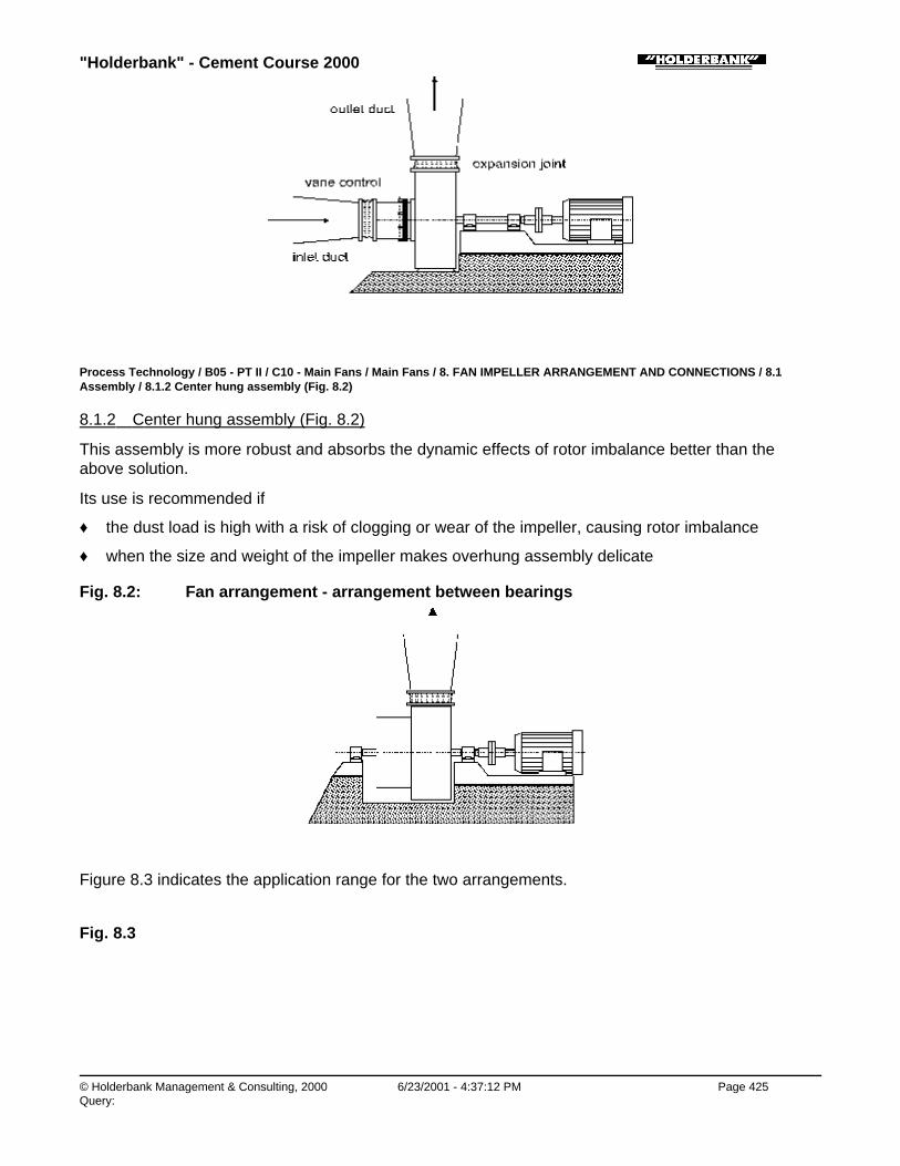
"Holderbank" - Cement Course 2000
© Holderbank Management & Consulting, 2000 6/23/2001 - 4:37:12 PM Page 425Query:
Process Technology / B05 - PT II / C10 - Main Fans / Main Fans / 8. FAN IMPELLER ARRANGEMENT AND CONNECTIONS / 8.1Assembly / 8.1.2 Center hung assembly (Fig. 8.2)
8.1.2 Center hung assembly (Fig. 8.2)
This assembly is more robust and absorbs the dynamic effects of rotor imbalance better than theabove solution.
Its use is recommended if
♦ the dust load is high with a risk of clogging or wear of the impeller, causing rotor imbalance
♦ when the size and weight of the impeller makes overhung assembly delicate
Fig. 8.2: Fan arrangement - arrangement between bearings
Figure 8.3 indicates the application range for the two arrangements.
Fig. 8.3

"Holderbank" - Cement Course 2000
© Holderbank Management & Consulting, 2000 6/23/2001 - 4:37:13 PM Page 426Query:
Process Technology / B05 - PT II / C10 - Main Fans / Main Fans / 8. FAN IMPELLER ARRANGEMENT AND CONNECTIONS / 8.2Foundations
8.2 Foundations
Fig. 8.4
1) Directly onto concrete with separate motor-bearing base-plate (this is the most economical solutionand most widely used).
2) Onto concrete with common base plate with centerline axis support maintaining therotor-bearing-motor alignment with the stator (more expensive solution, but easy to install onto thefoundations).Used for hot gas fans where thermal expansion must be taken into account.
3) Common base-plate with centerline axis support resting on anti-vibration mounts (this chassis mustbe perfectly rigid and is thus very expensive).Used only in very special cases (fans mounted on steel structures).
4) With spring-supported concrete block resting on anti-vibration mounts and supporting the fan (aspring supported block is less expensive than a common base-plate with centerline support andallows for remarkable vibration absorption. Its weight, between 10 - 60 tons must be included indesign calculations).Used only in very special cases.

"Holderbank" - Cement Course 2000
© Holderbank Management & Consulting, 2000 6/23/2001 - 4:37:13 PM Page 427Query:
Process Technology / B05 - PT II / C10 - Main Fans / Main Fans / 8. FAN IMPELLER ARRANGEMENT AND CONNECTIONS / 8.3Connections
8.3 Connections
Process Technology / B05 - PT II / C10 - Main Fans / Main Fans / 8. FAN IMPELLER ARRANGEMENT AND CONNECTIONS / 8.3Connections / 8.3.1 Inlet connections
8.3.1 Inlet connections
Process Technology / B05 - PT II / C10 - Main Fans / Main Fans / 8. FAN IMPELLER ARRANGEMENT AND CONNECTIONS / 8.3Connections / 8.3.2 Outlet connections
8.3.2 Outlet connections

"Holderbank" - Cement Course 2000
© Holderbank Management & Consulting, 2000 6/23/2001 - 4:37:13 PM Page 428Query:
Process Technology / B05 - PT II / C10 - Main Fans / Main Fans / 9. INFORMATION SOURCES
9. INFORMATION SOURCES
♦ Robinson Industries, Inc., Zelienople, PA, USA
♦ TLT-Babcock, Inc., Akron, Ohio, USA
♦ Venti Oelde, Oelde, Germany
♦ Solyvent-Ventec, Chalon-Sur-Saône, Cedex, France
♦ Balance Dynamics Corporation, Ann Arbor, Michigan, USA, Fax # 313 994 3690