Embed Size (px)
Citation preview
This report has been reviewed by the Bureau of Safety and Environmental Enforcement and approved for
publication. Approval does not signify that the contents necessarily reflect the views and policies of the
Cement Plug Testing: Weight vs. Pressure Testing to Assess Viability of a Wellbore Seal Between Zones
RLS0116
Prepared For: Timothy Steffek
Date: 12-14-11
Prepared By: CSI Technologies
BUREAU OF SAFETY AND
ENVIRONMENTAL ENFORCEMENT
381 ELDEN STREET
HERNDON, VA 20170
Service, nor does mention of the trade names or commercial products constitute endorsement or
recommendation for use.
This study was funded by the Bureau of Safety and Environmental Enforcement, U.S. Department of the
Interior, Washington D.C., under Contract Number M10PC00113
CTMS-TM-PM-03(01)
Cement Bond Strength Requirement 12
Bond Strength Comparison 12
Horse Collar Calculations 14
Laboratory Evaluation 16
Small Scale 16
Blend Formulations 16
Table of Contents Objective 1
Recommendations 1
Conclusions 1
Future Work 2
Summary of Results 2
Current Seal Integrity Evaluation 2
Literature Review 3
Engineering Study 3
Laboratory Evaluation 3
Field Operations 3
Engineering Correlation 3
Detailed Discussion of Results 4
Literature Review 4
Well Plugging Methods 4
Well Plugging Fundamentals from Case Studies 4
Current Guidelines for Plugging Methods and Quality Assurance 4
Plugging State of the Art, Issues, and Technology Deficits 5
Initial Design/Planning 5
Field Execution 6
Plug Performance Testing/Evaluation 6
Engineering Study 7
Qualitative Analysis 7
Cement Density 7
Pipe Condition 8
Crystalline Expansion Properties 9
The Use of Bonding Agents in Cement Blends 9
Engineering Analysis 10
Hydraulic Bond Strength 10
Shear Bond Strength 11
CTMS-TM-PM-03(01)
Mechanical Properties 17
Shear/Hydraulic Bond Strength 19
Compressive Strength Development 22
Pressure Annular Seal 23
Large Scale 25
8ft Perm 25
Hydration Volume Reduction 26
20ft Perm 33
Plug placement methods 34
Density variations 37
Field Operation Study 41
Cement Jobs Completed Summary 41
Engineering Correlations 53
Current Plug Testing Assessment 55
Surface Pump Pressure Test 56
Drill Pipe Weight Test 56
Recommendations for Plug Testing 57
References 58
Appendix A: Literature Review Summaries 59
Appendix B: Laboratory Data 84
CTMS-TM-PM-03(01)

Objective The objective of this project was to establish an optimized method for evaluating cement plug seal
integrity for well abandonment built on a comprehensive engineering study of the fundamentals
governing cement plug seal performance. This project consisted of laboratory and field investigations to
assess the necessary attributes of the seal formed by a cement plug, and to determine the effects of
wellbore geometry, cement properties, and placement methods on these attributes. Bond and seal
effectiveness determined by current plug evaluation methods required by 30CFR250.1715(b) were
evaluated in light of potential leak pathways and failure mechanisms. Analysis of the information from
the assessment of current verification methods, leak pathways, failure modes, cement properties,
wellbore geometry, and placement methods identified an optimum verification method for cement plug
seal, as well as a correlation relating well geometry, cement properties, and placement methods to
potential for forming an effective seal.
Recommendations Based on the results and conclusions from this work, the recommended optimal method of testing
cement plug seal integrity is:
All cement plugs should be tagged for verification of cement top, tagging can be performed with
slick-line and no specific weight test is required
All cement plugs should be pressure tested to current specified pressure test values (1000psi)
A negative pressure gas bubble observation should be performed on all plugs after wait-on
cement time to verify seal against gas migration
CSI interviewed several service companies that are currently performing cementing operations in the
Gulf of Mexico as well as a Decommissioning Operators Group to gain a better insight on current
industry best practices and the slight differences between current regulatory requirements. These
recommendations were based on comprehensive research supplemented by engineering studies,
laboratory testing, and field observation.
Conclusions Weight test measures plug location not seal effectiveness
ΠΉͼΆφ φμφ Ήμφ ΩεθφΉΩΛΛϳ μΉΛ in rig-less operations and poses a higher safety concern
Weight test is less stringent of a seal effectiveness test when compared to surface pump
pressure test
Surface pressure verification of cement seal integrity is significant only on the initial plug
covering perforated zones or formation. Pressure leaks detected in subsequent plug testing
indicate casing leaks rather than plug seal failure (μ μφΉΩ Fϡφϡθ ΠΩθΘ)
Several factors affect cement seal integrity: cement fluid characteristics, well-bore deviation,
placement techniques, slurry volume, etc.
Few engineering studies have examined cement seal performance testing.
CSI Technologies makes no representations or warranties, either expressed or implied, and specifically provides the results of this report "as is” based upon the provided information.
1
Required bond strength varies depending on the cement plug geometry and the effective length
of the cement plug.
Placement success varies greatly depending on: cement density, pipe condition, crystalline
expansion properties, and the use of bonding agents in cement blend such as latex or
surfactants
Cement plug stability plays a very large role in bond strength development.
There is a fundamental difference in failure modes between the weight test and the pressure
test.
Longer cement cure times generally reduce the risk of failure because cement bond strength
develops over time.
As long as there is bond, there is no need to worry about long term cement/pipe interface gas
migration from hydration volume reduction.
Plug integrity and location are greatly affected from fluid swapping in balanced plug conditions
Use of an artificial bottom (CIBP, Viscous pill, etc.) greatly decreases the risk of plug instability
Most field operations generally utilize neat cement blends for P&A operations
It is currently not required to test plug stability on intermediate plugs
Future Work Although this report did investigate the best way to evaluate cement plugs in P&A applications there still
remains several issues that should be investigated further. First as specified in the conclusions the
pressure test recommended only applies differential pressure across the bottom plug in the wellbore.
The other plugs further up the hole do not experience the differential pressure when the 1000 psi test
pressure is applied. Other techniques and methods may be available or developed to provide more
appΛΉΛ ΉΩθΡφΉΩ Ωϡφ φΆ ΉφͼθΉφϳ Ω φΆμ ϡεεθ εΛϡͼμ΄ ΐΆΉμ ϭΩϡΛ θηϡΉθ μΩΡ ΉφΉΩΛ
research to determine.
Secondly the degree of intermixing of the cement plugs with wellbore fluids should be investigated
more thoroughly. It was shown by this work that the cement would readily intermix with the sea water
below it. The degree of mixing and the ultimate length of plug needed to insure competent cement once
placed was not determined. A method could be developed to determine the diluted plug length based
upon various parameters to insure plug integrity. This would also require additional research focus.
Summary of Results
Current Seal Integrity Evaluation After evaluation of current seal integrity tests, it was found that the weight test measures plug location
and not seal effectiveness. It was also found that the surface pressure test verifies perforation or casing
leaks and not the integrity of the cement. Neither of the current testing methods verifies plug stability
on intermediate plugs because testing is not currently required for these very important plugs. CSI
CSI Technologies makes no representations or warranties, either expressed or implied, and specifically provides the results of this report "as is” based upon the provided information.
2

recommends that all flow path barriers, including mechanical barriers, should be tested for seal
effectiveness when plugging a well.
Literature Review Plugging methods are generally rudimentary, but special attention is needed to design sufficient P&A
operations. Several factors affect cement plug seal integrity including: cement fluid characteristics, well-
bore deviation, placement techniques, in-situ drilling/completion fluid, fluid contamination, insufficient
slurry volume, and poor communication between operators and service companies. The majority of
technical documents touched on the critical nature of job execution. On the whole, there are a limited
number of studies regarding cement seal performance testing.
Engineering Study Current seal integrity verification methods allow for large variances in required plug bond strength.
Required bond strength varies depending on the cement plug geometry and the effective length of the
cement plug. Effective plug length is defined as the length of the cement plug which is sufficiently
bonded to the outer walls. Cement plug integrity plays a very large role in bond strength development.
Cement plug integrity is influenced by the cement density, the condition of the pipe, and the additives
used in the cement.
Laboratory Evaluation There is a fundamental difference in failure modes between the weight test and the pressure test. This
difference in failure modes causes hydraulic bond failure strengths to differ greatly from shear bond
failure strengths. It was found that longer cure times of the cement will reduce the risk of failure
because cement bond strength develops, and in some cases retrogresses, over time. Plug integrity and
location is greatly affected from fluid swapping in balanced plug conditions where a higher density fluid
is placed on top of a lower density fluid.
Field Operations The majority of plug operations performed in the Gulf of Mexico use neat cement with few additives.
The pump pressure test is the preferred method of seal integrity verification, especially in shallow water
or rig-less abandonment operations. One additional test performed on location to verify gas migration
risks is the static bubble observation. Several case studies were completed and laboratory confirmation
testing to simulate field operations was also performed.
Engineering Correlation Utilizing realistic bond strength based on cement and well conditions rather than a single magnitude of
pressure or force application will yield a much more standardized approach to plug testing. Minimum
bond strengths of 15 psi were used to calculate weight tests and pump pressures for failure. It was
found that the pump pressure test is the more severe and feasible method for plug testing.
CSI Technologies makes no representations or warranties, either expressed or implied, and specifically provides the results of this report "as is” based upon the provided information.
3
Detailed Discussion of Results
Literature Review An extensive literature review was performed which covered plugging and abandoning wells, problems
and issues with seal integrity, and assessment of seal effectiveness. Results from this literature review
have been applied to fine-tune and finalize testing and analysis. Detailed summaries of technical
literature documents can be found in Appendix A. The findings from the literature review are discussed
below.
Well Plugging Methods
From review of technical literature, the three most commonly used plugging methods are:
1. Balanced Plug Method
2. Wire Line Dump Bailer Method
3. �ΩΉΛ ΐϡΉͼ ϡΡε ϡΛΛ ͰφΆΩ
These three plugging methods all have their own advantages and disadvantages and have case specific
applications. The balanced plug method is one of the most widely used methods for plugging and/or
abandoning. Generally if cement plugs of small volume are needed to be placed very accurately then
φΆ ϡΡε ΉΛθ ΡφΆΩ Ήμ εθθθ΄ ΠΆ ΛΩͼ εΛϡͼμ θ θηϡΉθ φΆ φΆ �ΐ ϡΡε ϡΛΛ
method should be used.
Other notable, but somewhat infrequent plugging methods which were discussed within the technical
documentation were:
Pumping/Pouring resin downhole to form plugs at required depths
Using sacrificial fiberglass tubing which is left in cement during setting
Various wire line combination tools (e.g. perforate and dump)
2 part activator and silica plug blends and methods of placement
Well Plugging Fundamentals from Case Studies
Upon review of technical literature, the majority of case studies revealed that special attention has to be
given to plug and abandonment design. Improper initial design of cement plugs will increase the
likelihood of failed plugging operations. It was found that cement plugs generally fail because of many
factors which include, but are not limited to: cement fluid characteristics/density, well-bore deviation,
placement techniques, in situ drilling/completion fluid, fluid contamination, insufficient slurry volume,
and poor communication. Most case studies commented that some or all of these factors had
detrimental effects on cement plug success.
Current Guidelines for Plugging Methods and Quality Assurance
The review of technical literature relating to plug and abandonment revealed multiple industry best
practices used during plugging operations. Some of the best practices were related to case specific
CSI Technologies makes no representations or warranties, either expressed or implied, and specifically provides the results of this report "as is” based upon the provided information.
4
procedures but many of them were general to all plug and abandonment operations. These best
practices include, but are not limited to:
General Industry Best Practices o Hole preparation prior to plugging operations is very important o Mechanical barriers are strongly recommended for all plugging operations o Cement slurry should be tested for stability o Accurate placement of cement is a must o Cement must be allowed sufficient time to set before continuing operations
Balanced Plug Method Best Practices o The use of spacers/pre-flushes to remove mud and water wet annular surfaces o The use of diverters on the end of the work string are recommended o Pull drill string out of plug at very slow rates after placement
Wire Line Dump Bailer Method Best Practices o Very low gel strength development of slurry is a must o Cement should be dumped as close to the bridge as possible to minimize dilution o The use of resin is a better choice for plugging gravel packs
�ΩΉΛ ΐϡΉͼ ϡΡε ϡΛΛ ͰφΆΩ �μφ θφΉμ o Surface batch mixing cement prior to placement o Monitor mixing energy o Use of diverters on the end of the tubing
Plugging State of the Art, Issues, and Technology Deficits
Upon review of technical literature the current plugging state of the art can be separated into three
categories: Initial design/planning, field execution, and plug performance testing/evaluation.
Initial Design/Planning
Before the BSEE (formally MMS) amendment to plug design regulations which now requires professional
engineer certification of plug designs, there was very little scrutiny relating to the design process for
abandonment operations.
Issues:
Generally, the plug and abandonment design process is an overlooked issue which is considered
rudimentary and only given serious thought once the well is in actual need of abandonment operations.
Related technical literature generally comments that operators can never start planning abandonment
operations too early. Ideally, a well abandonment plan should be part of the process of planning the
development of a field.
Technology Deficits
CSI Technologies makes no representations or warranties, either expressed or implied, and specifically provides the results of this report "as is” based upon the provided information.
5
The major technology deficit relating to the design of abandonment plugs generally relates to poor
initial designs of plugging operations because of partially undefined well conditions. The engineer
initially designing these plugs with expectations of success must have a clear representation of the
downhole conditions in order to design accordingly. Normally, there are multiple unknown
circumstances whose risk potentials are estimated throughout the design process.
Field Execution
The value of all plug designs depends on how the design was executed in the field. Job execution is
critical to plug and abandonment success. Plugging operations that follow design and placement
procedures described achieve better results than guesstimating implementation on location. Cementing
success is considered to be 10% design and 90% placement/execution.
Issues
There are two major issues relating to successful field execution of abandonment plugs currently;
communication and equipment. Lack of proper communication between engineers and operators on
location generally leads to execution inaccuracies which increase the likelihood of plug failure after
placement. The quality of the cement mixing equipment on location plays a very large role in plug
success as well.
Technology Deficits
Cement contamination is considered the major technology deficit that plagues the industry during plug
and abandonment operations. There are many methods and best practices that are used to minimize
the cement contamination but as of current, there is no documented procedure that completely
eradicates the likelihood of even partial cement contamination. The general practice in anticipation of
cement contamination is to pump larger volumes than needed such that the volume of uncontaminated
cement will be equivalent to the desired plug length. This practice, although helpful, is still a large
technological deficit in regards to field execution.
Plug Performance Testing/Evaluation
Cement plug performance testing/evaluation is the cornerstone to all abandonment operations. An
insufficient isolation of a zone can lead to many unwanted well conditions and may even pollute the
environment. This is the main reason why all oilfield regulatory bodies require cement plug
performance testing/evaluation for abandonment operations.
Issues
One of the major issues relating to plug performance testing is the dichotomy between laboratory and
field performance testing procedures. Currently there are only a few specific methods of testing cement
plug success from a laboratory standpoint and even fewer methods in the field. Also, there is no simple
way of accurately testing cement plugs under expected downhole conditions in laboratories. Most
laboratory testing specific to cement plug testing assumes best case scenario in regards to cement
contamination and bonding ability.
CSI Technologies makes no representations or warranties, either expressed or implied, and specifically provides the results of this report "as is” based upon the provided information.
6
Technology Deficits
The major technology deficit related to cement plug performance testing is laboratory validation. Most
laboratories do not have access to equipment that is sophisticated enough to run tests that are specific
to plugging operations. These tests include: cement mechanical properties, shear bond, hydraulic bond,
fluid migration analysis, static gel strength analysis, and annular seal performance testing. From review
of literature, there is also very few studies conducted on plug performance testing/validation. Generally
the only validation of a successful cement plug is by field testing after placement either by the pump
pressure test or the drill pipe tag test.
Engineering Study Best practices for evaluating cement plug seal for well abandonment, built on a comprehensive
engineering study of the fundamentals governing cement plug seal performance are discussed within
this section. This portion of study evaluates cement mechanical properties required to maintain seal
integrity under various well conditions and plug configurations.
Hydraulic bond strength requirement vs. pipe diameter and plug length required to satisfy
hydraulic pressure requirement. (1,000 psi pump pressure test) were calculated
Shear bond strength requirement vs. pipe diameter and plug length required to satisfy weight
support criterion. (15,000 lb drill pipe tag test) were calculated
Qualify mechanical properties of cement and other possible sealing materials across a range of
applicable densities.
Qualitative Analysis
The resulting placement quality of any size cement plug generally varies with the effect of these
properties
Cement Density
Pipe Condition
Crystalline Expansion Properties
The Use of Bonding Agents in Cement Blends (Latex/Surfactants)
These four properties will be briefly discussed as to how they affect the overall outcome of plug
cementing and the cements ability to build bond strength in a well bore.
Cement Density
Density plays a very large role in cements ability to build compressive strength and bond strength. The
general industry practice is to pump cement plugs that are as close to their neat composition such that
the blends will develop well documented compressive strengths. Certain downhole situations dictate
the modification of cement density. These situations can lead to cement with much lower bond
CSI Technologies makes no representations or warranties, either expressed or implied, and specifically provides the results of this report "as is” based upon the provided information.
7
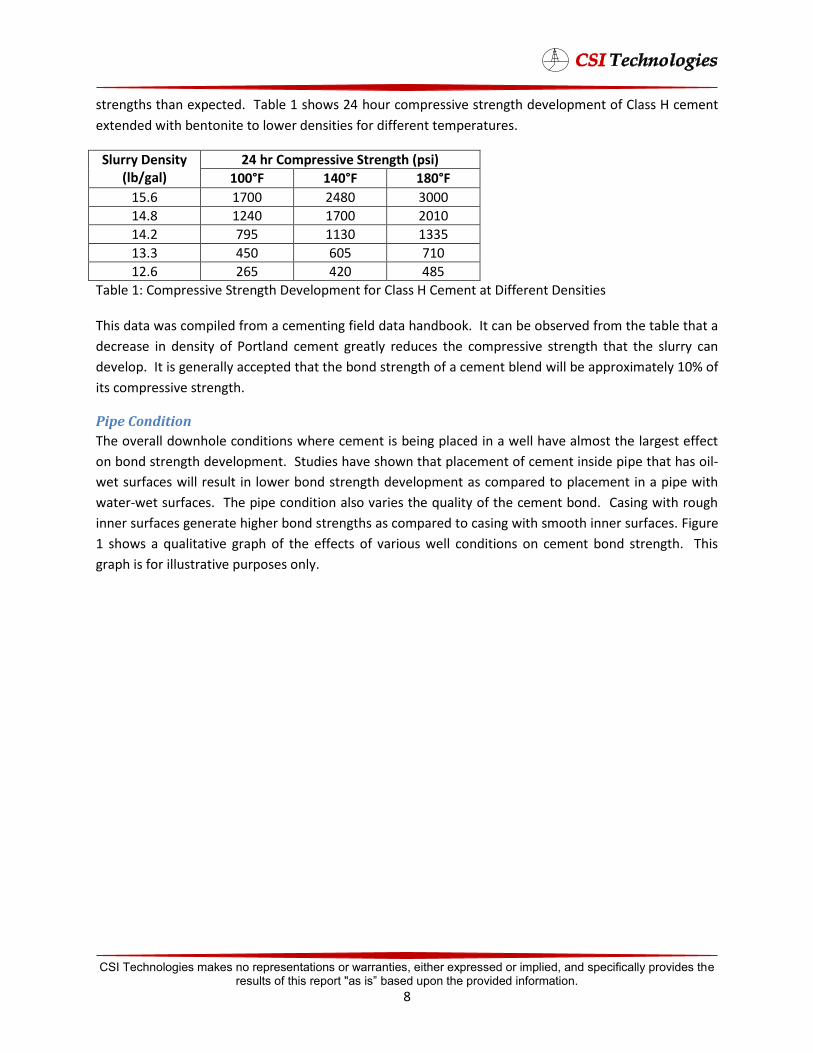
strengths than expected. Table 1 shows 24 hour compressive strength development of Class H cement
extended with bentonite to lower densities for different temperatures.
Slurry Density 24 hr Compressive Strength (psi) (lb/gal) 100°F 140°F 180°F
15.6 1700 2480 3000
14.8 1240 1700 2010
14.2 795 1130 1335
13.3 450 605 710
12.6 265 420 485
Table 1: Compressive Strength Development for Class H Cement at Different Densities
This data was compiled from a cementing field data handbook. It can be observed from the table that a
decrease in density of Portland cement greatly reduces the compressive strength that the slurry can
develop. It is generally accepted that the bond strength of a cement blend will be approximately 10% of
its compressive strength.
Pipe Condition
The overall downhole conditions where cement is being placed in a well have almost the largest effect
on bond strength development. Studies have shown that placement of cement inside pipe that has oil-
wet surfaces will result in lower bond strength development as compared to placement in a pipe with
water-wet surfaces. The pipe condition also varies the quality of the cement bond. Casing with rough
inner surfaces generate higher bond strengths as compared to casing with smooth inner surfaces. Figure
1 shows a qualitative graph of the effects of various well conditions on cement bond strength. This
graph is for illustrative purposes only.
CSI Technologies makes no representations or warranties, either expressed or implied, and specifically provides the results of this report "as is” based upon the provided information.
8
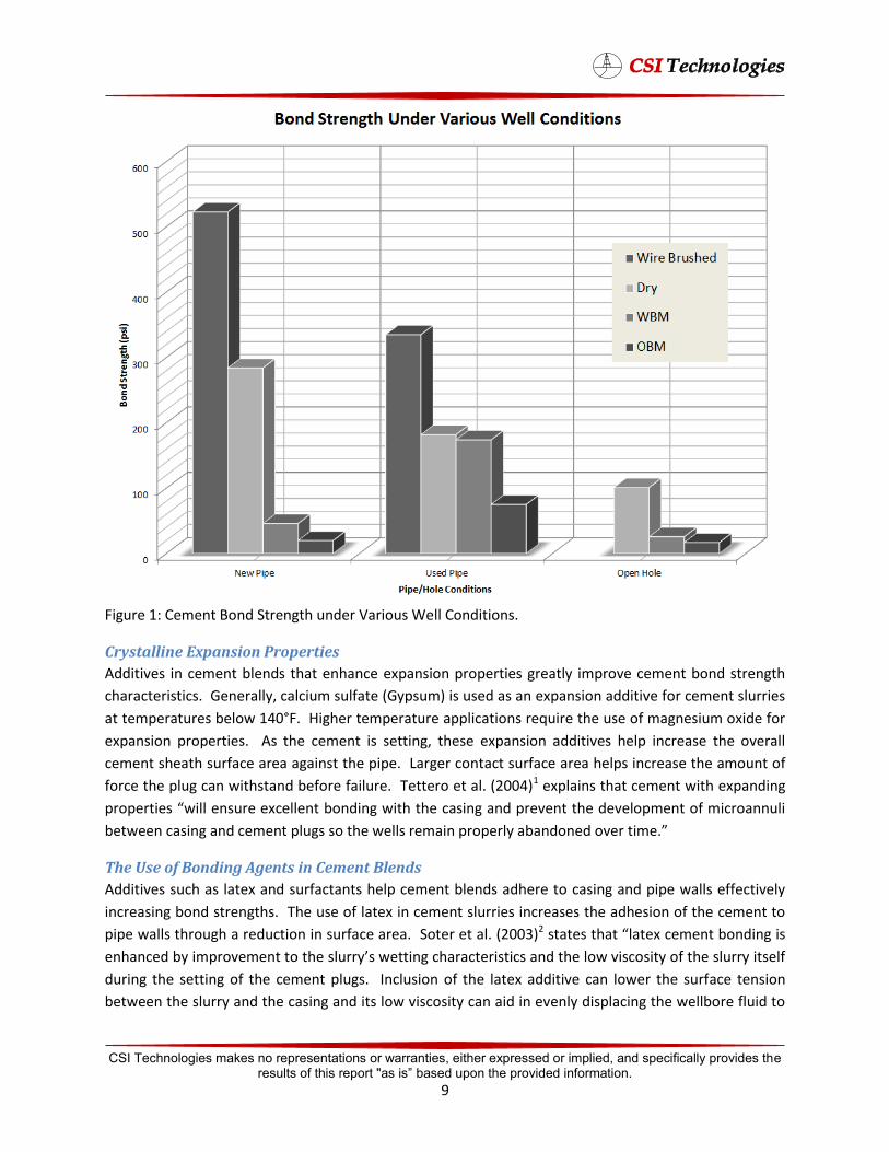
Figure 1: Cement Bond Strength under Various Well Conditions.
Crystalline Expansion Properties
Additives in cement blends that enhance expansion properties greatly improve cement bond strength
characteristics. Generally, calcium sulfate (Gypsum) is used as an expansion additive for cement slurries
at temperatures below 140°F. Higher temperature applications require the use of magnesium oxide for
expansion properties. As the cement is setting, these expansion additives help increase the overall
cement sheath surface area against the pipe. Larger contact surface area helps increase the amount of
force the plug can withstand before failure. Tettero et al. (2004)1 explains that cement with expanding
εθΩεθφΉμ ϭΉΛΛ μϡθ ϲΛΛφ ΩΉͼ ϭΉφΆ φΆ μΉͼ εθϬφ φΆ ϬΛΩεΡφ Ω ΡΉθΩϡΛΉ
betw μΉͼ Ρφ εΛϡͼμ μΩ φΆ ϭΛΛμ θΡΉ εθΩεθΛϳ Ω ΩϬθ φΉΡ΄
The Use of Bonding Agents in Cement Blends
Additives such as latex and surfactants help cement blends adhere to casing and pipe walls effectively
increasing bond strengths. The use of latex in cement slurries increases the adhesion of the cement to
pipe walls through a reduction in surface area. Soter et al. (2003)2 μφφμ φΆφ Λφϲ Ρφ ΩΉͼ Ήμ
Ά ϳ ΉΡεθΩϬΡφ φΩ φΆ μΛϡθθϳμ ϭφφΉͼ ΆθφθΉμφΉμ φΆ ΛΩϭ ϬΉμΩμΉφϳ Ω φΆ μΛϡθθϳ ΉφμΛ
during the setting of the cement plugs. Inclusion of the latex additive can lower the surface tension
between the slurry and the casing and its low viscosity can aid in evenly displacing the wellbore fluid to
CSI Technologies makes no representations or warranties, either expressed or implied, and specifically provides the results of this report "as is” based upon the provided information.
9
ΆΛε ΡΉΉΡΉϸ Ρφ ΩφΡΉφΉΩ΄ Ίϡθφφμ ΛμΩ ΆΛε Ή θΡΩϬΉͼ ΩΉΛ-wet surfaces from annular
walls allowing better bonding contact during setting.
Engineering Analysis
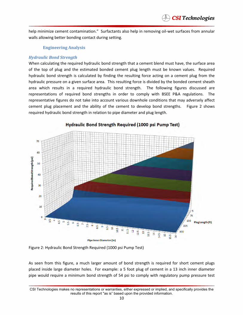
Hydraulic Bond Strength
When calculating the required hydraulic bond strength that a cement blend must have, the surface area
of the top of plug and the estimated bonded cement plug length must be known values. Required
hydraulic bond strength is calculated by finding the resulting force acting on a cement plug from the
hydraulic pressure on a given surface area. This resulting force is divided by the bonded cement sheath
area which results in a required hydraulic bond strength. The following figures discussed are
representations of required bond strengths in order to comply with BSEE P&A regulations. The
representative figures do not take into account various downhole conditions that may adversely affect
cement plug placement and the ability of the cement to develop bond strengths. Figure 2 shows
required hydraulic bond strength in relation to pipe diameter and plug length.
Figure 2: Hydraulic Bond Strength Required (1000 psi Pump Test)
As seen from this figure, a much larger amount of bond strength is required for short cement plugs
placed inside large diameter holes. For example: a 5 foot plug of cement in a 13 inch inner diameter
pipe would require a minimum bond strength of 54 psi to comply with regulatory pump pressure test
CSI Technologies makes no representations or warranties, either expressed or implied, and specifically provides the results of this report "as is” based upon the provided information.
10
requirements, whereas the same pipe with a 300 foot plug would need a bond strength of only 1 psi. It
can also be noticed that for most cement plugs which range in length between 75 foot and 300 foot,
very little bond strength is required to comply with regulatory standards.
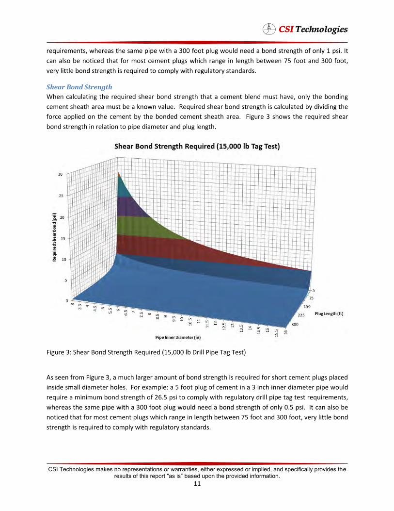
Shear Bond Strength
When calculating the required shear bond strength that a cement blend must have, only the bonding
cement sheath area must be a known value. Required shear bond strength is calculated by dividing the
force applied on the cement by the bonded cement sheath area. Figure 3 shows the required shear
bond strength in relation to pipe diameter and plug length.
Figure 3: Shear Bond Strength Required (15,000 lb Drill Pipe Tag Test)
As seen from Figure 3, a much larger amount of bond strength is required for short cement plugs placed
inside small diameter holes. For example: a 5 foot plug of cement in a 3 inch inner diameter pipe would
require a minimum bond strength of 26.5 psi to comply with regulatory drill pipe tag test requirements,
whereas the same pipe with a 300 foot plug would need a bond strength of only 0.5 psi. It can also be
noticed that for most cement plugs which range in length between 75 foot and 300 foot, very little bond
strength is required to comply with regulatory standards.
CSI Technologies makes no representations or warranties, either expressed or implied, and specifically provides the results of this report "as is” based upon the provided information.
11
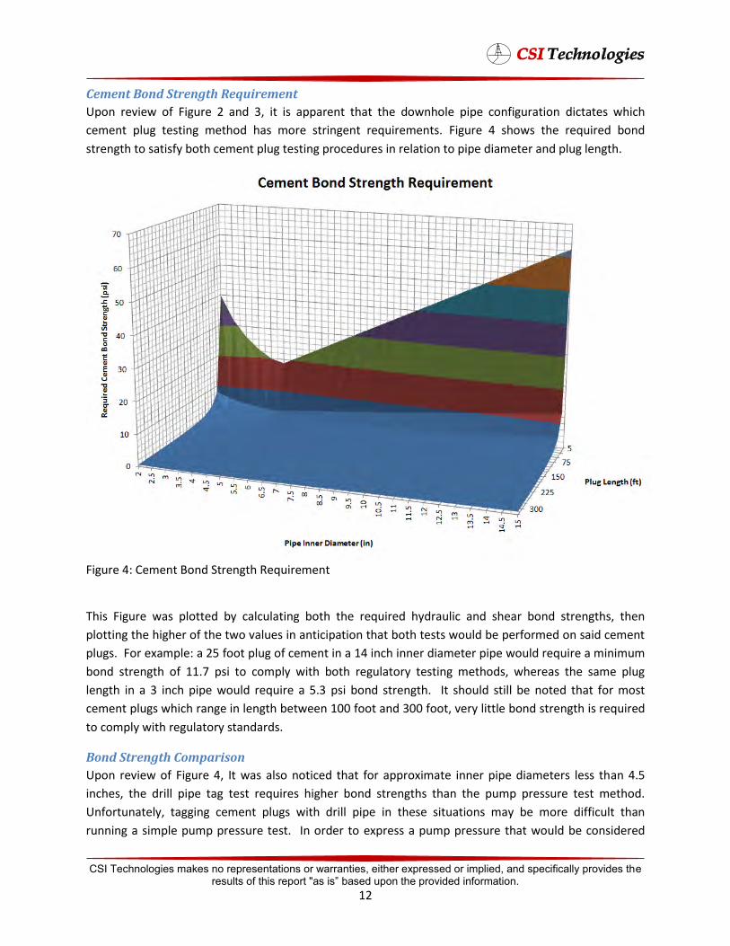
Cement Bond Strength Requirement
Upon review of Figure 2 and 3, it is apparent that the downhole pipe configuration dictates which
cement plug testing method has more stringent requirements. Figure 4 shows the required bond
strength to satisfy both cement plug testing procedures in relation to pipe diameter and plug length.
Figure 4: Cement Bond Strength Requirement
This Figure was plotted by calculating both the required hydraulic and shear bond strengths, then
plotting the higher of the two values in anticipation that both tests would be performed on said cement
plugs. For example: a 25 foot plug of cement in a 14 inch inner diameter pipe would require a minimum
bond strength of 11.7 psi to comply with both regulatory testing methods, whereas the same plug
length in a 3 inch pipe would require a 5.3 psi bond strength. It should still be noted that for most
cement plugs which range in length between 100 foot and 300 foot, very little bond strength is required
to comply with regulatory standards.
Bond Strength Comparison
Upon review of Figure 4, It was also noticed that for approximate inner pipe diameters less than 4.5
inches, the drill pipe tag test requires higher bond strengths than the pump pressure test method.
Unfortunately, tagging cement plugs with drill pipe in these situations may be more difficult than
running a simple pump pressure test. In order to express a pump pressure that would be considered
CSI Technologies makes no representations or warranties, either expressed or implied, and specifically provides the results of this report "as is” based upon the provided information.
12
ݬ ݐݡݭݎݰݐݯ ݐݭݎݏ ݩ ݒ ݭݑݭݰݐݩݭݰݡ ݚ
ݭ ݭݒݴݴݱݎݱݞ ݐݰݯݱݭݥݯݩݢ ݒݴݴݱݎݱݞ ݐݰݯݱݭݥݯݩݢ ݐ
ݑݞݭݎݞ ݏݏݑݭݎ܇ ݎݑ ݏݏ ݐݫݭݡݴݩݱݭݎݏ ݩݑݞ ݭݎݞ ݏݏݎݑݭ܇ ݐݬ ݐݡݭݎݰݐݯޢ ݐݭݎݏ ݩ ݒ ݭݑݭݰݐݩݭݰݡ ݚ
ݐݬ ݐݡݎݯݭݰݐ܇ ݑݭݐݭ ݰݐݩݭݰݡݏ ݎݩݭݐݬ ݐݡݎݯݭ ݰݐ܇
ݑݞ ݞݎݏݭݏݑݎݭݒ ݚ
ݒ ݑݎݏݏ ݫݭݡݱݐݴݩݏݎݩݭ
ޢ
equivalent to drill pipe tag weight for these conditions, one must set the resulting hydraulic bond
strength equal to the resulting shear bond strength. Required shear bond strength in terms of drill pipe
tag weight is calculated as:
Required hydraulic bond strength in terms of pump pressure is calculated as:
ݒ
By solving the above equation for pump pressure, the result is as follows:
By substituting the shear bond strength values that were calculated from drill pipe tag weight one can
get an equivalent pump pressure in terms of drill pipe tag weight shown below:
ݑݞ ݭݎݑݏݏݭݎݞ
ݐݰݯݱݭݥ ݯݩݢ ݭݱݞ ݴݴݱݎݒ ݚ ݒ
ݚ ݒ
ݒ
ޢ
ݐݰݯݱݭݥ ݯݩݢ ݭݱݞ ݴݴݱݎݒ
ݏݏݎݑ ݴݩݱݐݫݭݡ ݩݭݎݏ
It was observed that because the pump pressure is now calculated from tag weight bond strengths, the
cement sheath areas cancel out of the equation making equivalent pump pressures independent of plug
length. Figure 5 depicts the equivalent pump pressure test requirement to adhere to the drill pipe tag
test method for small pipe inner diameters.
CSI Technologies makes no representations or warranties, either expressed or implied, and specifically provides the results of this report "as is” based upon the provided information.
13
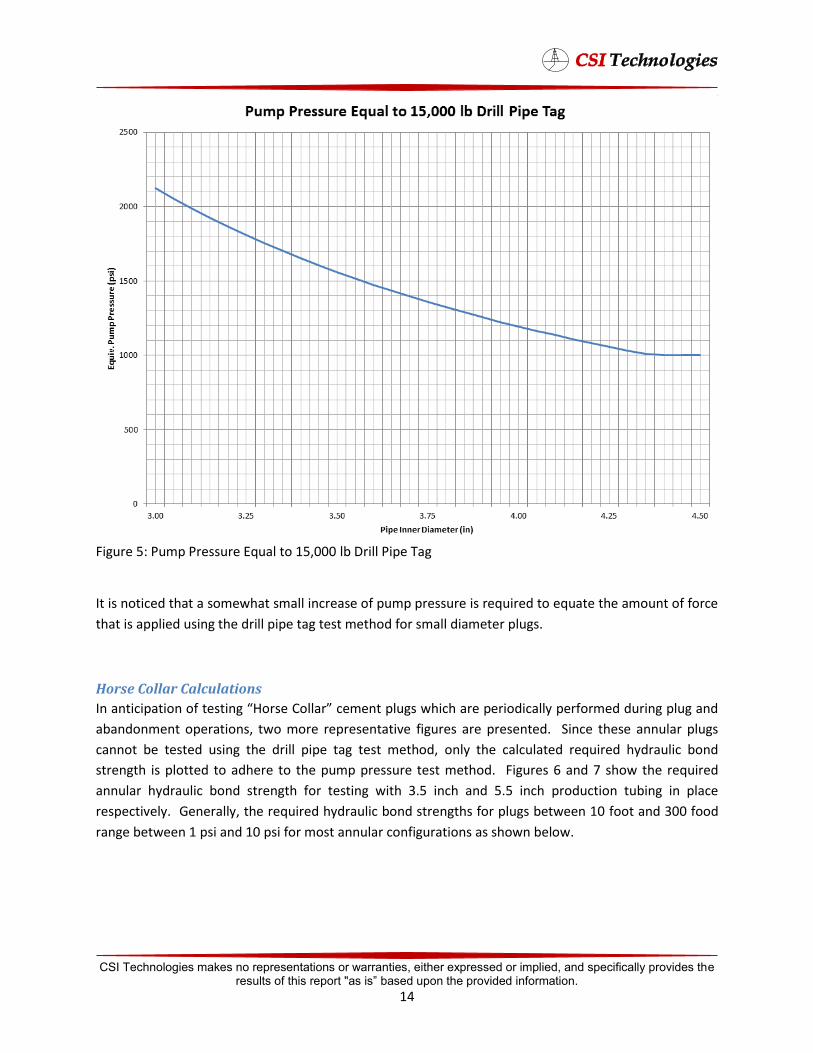
Figure 5: Pump Pressure Equal to 15,000 lb Drill Pipe Tag
It is noticed that a somewhat small increase of pump pressure is required to equate the amount of force
that is applied using the drill pipe tag test method for small diameter plugs.
Horse Collar Calculations
φΉΉεφΉΩ Ω φμφΉͼ HΩθμ �ΩΛΛθ Ρφ εΛϡͼμ ϭΆΉΆ θ εθΉΩΉΛΛϳ εθΩθΡ ϡθΉͼ εΛϡͼ
abandonment operations, two more representative figures are presented. Since these annular plugs
cannot be tested using the drill pipe tag test method, only the calculated required hydraulic bond
strength is plotted to adhere to the pump pressure test method. Figures 6 and 7 show the required
annular hydraulic bond strength for testing with 3.5 inch and 5.5 inch production tubing in place
respectively. Generally, the required hydraulic bond strengths for plugs between 10 foot and 300 food
range between 1 psi and 10 psi for most annular configurations as shown below.
CSI Technologies makes no representations or warranties, either expressed or implied, and specifically provides the results of this report "as is” based upon the provided information.
14
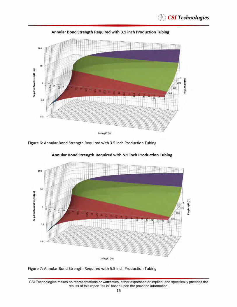
Figure 6: Annular Bond Strength Required with 3.5 inch Production Tubing
Figure 7: Annular Bond Strength Required with 5.5 inch Production Tubing
CSI Technologies makes no representations or warranties, either expressed or implied, and specifically provides the results of this report "as is” based upon the provided information.
15

Laboratory Evaluation An extensive laboratory evaluation of cement properties that affect plug seal integrity was conducted.
Cement properties that were studied included strength development and admixtures to improve bond
strength or prevent gas cut. Both small scale and large scale testing was performed on several blends to
better match a wider range of plugging conditions. Blend formulations and laboratory data summaries
of blends are shown in Appendix B. The results are discussed below.
Small Scale
All small scale testing was performed within the laboratory. All general laboratory testing such as
thickening time or rheology was performed prior to specific blend testing such as shear/hydraulic bond
and pressure annular seal
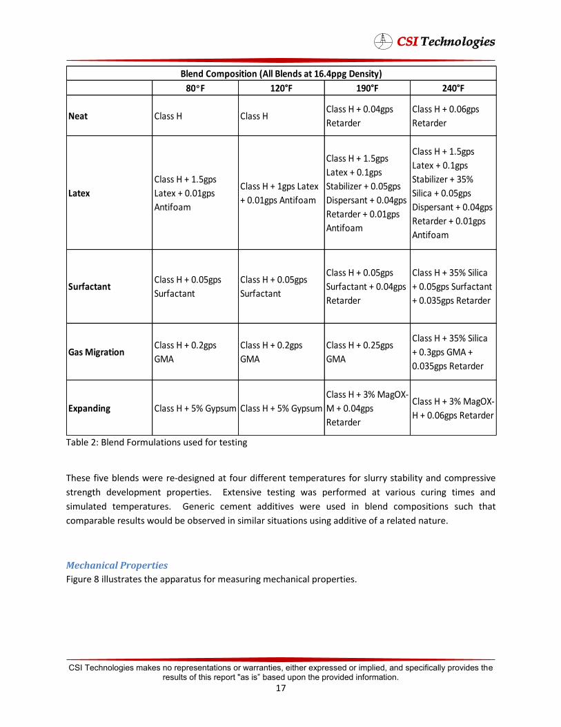
Blend Formulations
Table 2 shows the blend formulations for all cement blends.
CSI Technologies makes no representations or warranties, either expressed or implied, and specifically provides the results of this report "as is” based upon the provided information.
16
80°F 120°F 190°F 240°F
Neat Class H Class HClass H + 0.04gps
Retarder
Class H + 0.06gps
Retarder
Latex
Class H + 1.5gps
Latex + 0.01gps
Antifoam
Class H + 1gps Latex
+ 0.01gps Antifoam
Class H + 1.5gps
Latex + 0.1gps
Stabilizer + 0.05gps
Dispersant + 0.04gps
Retarder + 0.01gps
Antifoam
Class H + 1.5gps
Latex + 0.1gps
Stabilizer + 35%
Silica + 0.05gps
Dispersant + 0.04gps
Retarder + 0.01gps
Antifoam
SurfactantClass H + 0.05gps
Surfactant
Class H + 0.05gps
Surfactant
Class H + 0.05gps
Surfactant + 0.04gps
Retarder
Class H + 35% Silica
+ 0.05gps Surfactant
+ 0.035gps Retarder
Gas MigrationClass H + 0.2gps
GMA
Class H + 0.2gps
GMA
Class H + 0.25gps
GMA
Class H + 35% Silica
+ 0.3gps GMA +
0.035gps Retarder
Expanding Class H + 5% Gypsum Class H + 5% Gypsum
Class H + 3% MagOX-
M + 0.04gps
Retarder
Class H + 3% MagOX-
H + 0.06gps Retarder
Blend Composition (All Blends at 16.4ppg Density)
Table 2: Blend Formulations used for testing
These five blends were re-designed at four different temperatures for slurry stability and compressive
strength development properties. Extensive testing was performed at various curing times and
simulated temperatures. Generic cement additives were used in blend compositions such that
comparable results would be observed in similar situations using additive of a related nature.
Mechanical Properties
Figure 8 illustrates the apparatus for measuring mechanical properties.
CSI Technologies makes no representations or warranties, either expressed or implied, and specifically provides the results of this report "as is” based upon the provided information.
17
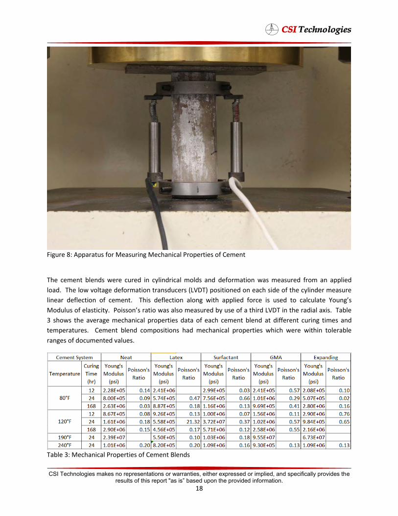
Figure 8: Apparatus for Measuring Mechanical Properties of Cement
The cement blends were cured in cylindrical molds and deformation was measured from an applied
load. The low voltage deformation transducers (LVDT) positioned on each side of the cylinder measure
linear deflection of cement. This deflectΉΩ ΛΩͼ ϭΉφΆ εεΛΉ Ωθ Ήμ ϡμ φΩ ΛϡΛφ ΦΩϡͼμ
ͰΩϡΛϡμ Ω ΛμφΉΉφϳ΄ ΩΉμμΩμ θφΉΩ ϭμ ΛμΩ Ρμϡθ ϳ ϡμ Ω φΆΉθ ΟDΐ Ή φΆ θΉΛ ϲΉμ΄ ΐΛ
3 shows the average mechanical properties data of each cement blend at different curing times and
temperatures. Cement blend compositions had mechanical properties which were within tolerable
ranges of documented values.
Table 3: Mechanical Properties of Cement Blends
CSI Technologies makes no representations or warranties, either expressed or implied, and specifically provides the results of this report "as is” based upon the provided information.
18
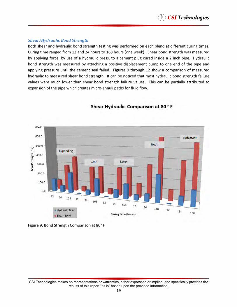
Shear/Hydraulic Bond Strength
Both shear and hydraulic bond strength testing was performed on each blend at different curing times.
Curing time ranged from 12 and 24 hours to 168 hours (one week). Shear bond strength was measured
by applying force, by use of a hydraulic press, to a cement plug cured inside a 2 inch pipe. Hydraulic
bond strength was measured by attaching a positive displacement pump to one end of the pipe and
applying pressure until the cement seal failed. Figures 9 through 12 show a comparison of measured
hydraulic to measured shear bond strength. It can be noticed that most hydraulic bond strength failure
values were much lower than shear bond strength failure values. This can be partially attributed to
expansion of the pipe which creates micro-annuli paths for fluid flow.
Figure 9: Bond Strength Comparison at 80° F
CSI Technologies makes no representations or warranties, either expressed or implied, and specifically provides the results of this report "as is” based upon the provided information.
19
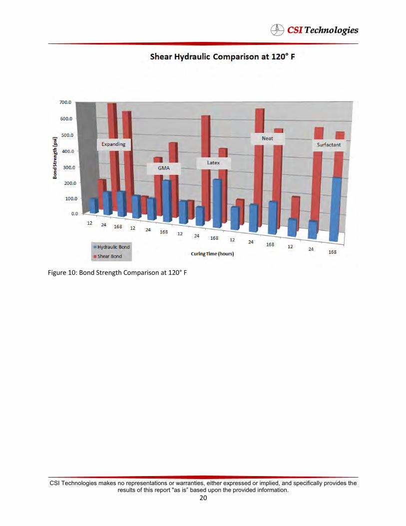
Figure 10: Bond Strength Comparison at 120° F
CSI Technologies makes no representations or warranties, either expressed or implied, and specifically provides the results of this report "as is” based upon the provided information.
20

Figure 11: Bond Strength Comparison at 190° F
CSI Technologies makes no representations or warranties, either expressed or implied, and specifically provides the results of this report "as is” based upon the provided information.
21
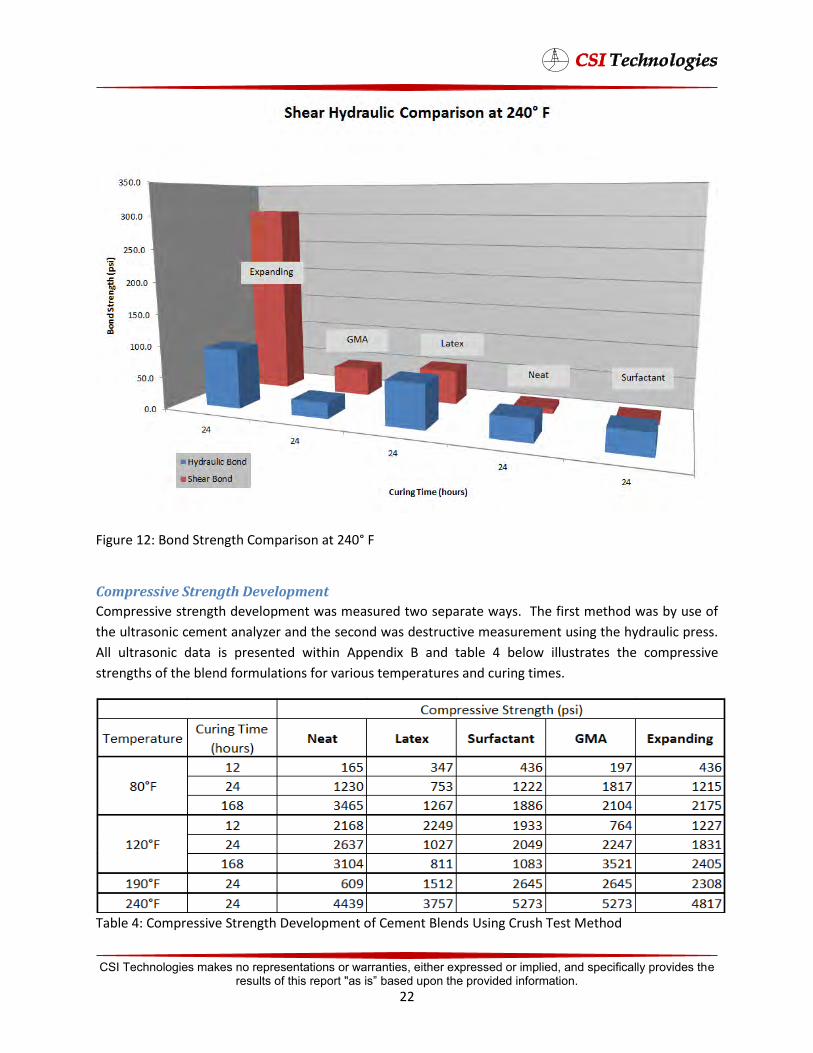
Figure 12: Bond Strength Comparison at 240° F
Compressive Strength Development
Compressive strength development was measured two separate ways. The first method was by use of
the ultrasonic cement analyzer and the second was destructive measurement using the hydraulic press.
All ultrasonic data is presented within Appendix B and table 4 below illustrates the compressive
strengths of the blend formulations for various temperatures and curing times.
Table 4: Compressive Strength Development of Cement Blends Using Crush Test Method
CSI Technologies makes no representations or warranties, either expressed or implied, and specifically provides the results of this report "as is” based upon the provided information.
22
Observations from compressive strength and bond strength testing shows that longer cure times
decrease the likelihood of cement plug failure.
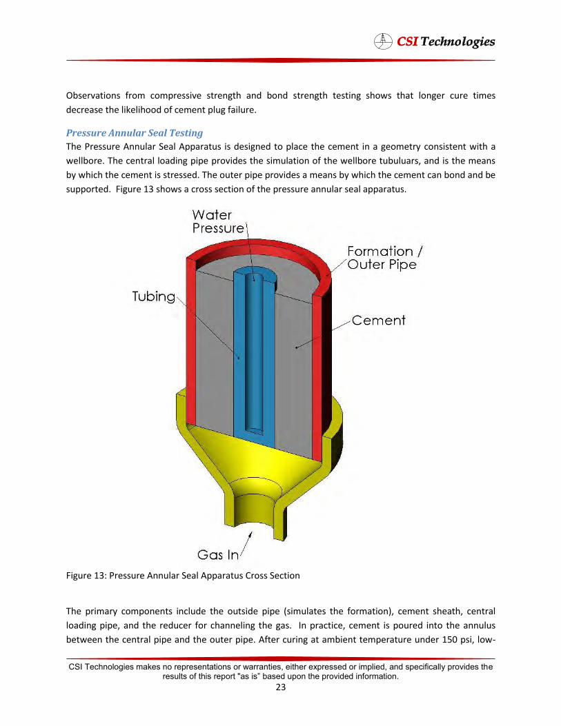
Pressure Annular Seal Testing
The Pressure Annular Seal Apparatus is designed to place the cement in a geometry consistent with a
wellbore. The central loading pipe provides the simulation of the wellbore tubuluars, and is the means
by which the cement is stressed. The outer pipe provides a means by which the cement can bond and be
supported. Figure 13 shows a cross section of the pressure annular seal apparatus.
Figure 13: Pressure Annular Seal Apparatus Cross Section
The primary components include the outside pipe (simulates the formation), cement sheath, central
loading pipe, and the reducer for channeling the gas. In practice, cement is poured into the annulus
between the central pipe and the outer pipe. After curing at ambient temperature under 150 psi, low-
CSI Technologies makes no representations or warranties, either expressed or implied, and specifically provides the results of this report "as is” based upon the provided information.
23
pressure gas is conducted through a flowmeter and into the inner end of the cement plug via the
reducer. The central pipe (blue) is alternately pressurized and depressurized to stress the cement
sheath. As long as the cement seal is intact, gas will not flow. This test measures the integrity of the
cement annular seal when stressed by imposing pressure in the internal pipe. Cement integrity is
determined by the ability of the cement to block nitrogen flow from the bottom to the top of the cell.
The gas pressure is maintained at 15 psi.
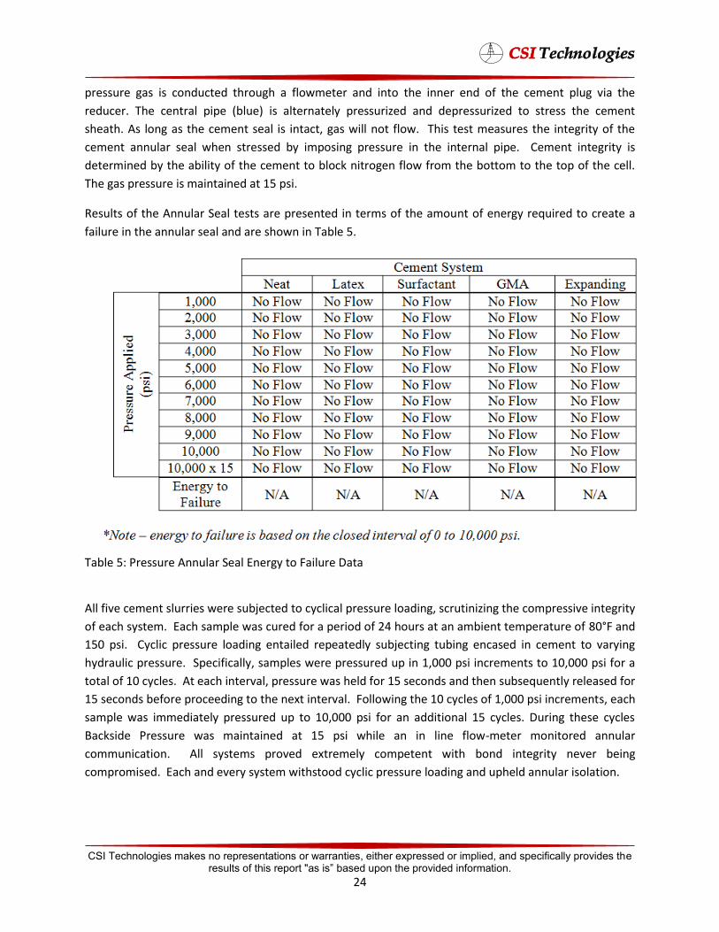
Results of the Annular Seal tests are presented in terms of the amount of energy required to create a
failure in the annular seal and are shown in Table 5.
Table 5: Pressure Annular Seal Energy to Failure Data
All five cement slurries were subjected to cyclical pressure loading, scrutinizing the compressive integrity
of each system. Each sample was cured for a period of 24 hours at an ambient temperature of 80°F and
150 psi. Cyclic pressure loading entailed repeatedly subjecting tubing encased in cement to varying
hydraulic pressure. Specifically, samples were pressured up in 1,000 psi increments to 10,000 psi for a
total of 10 cycles. At each interval, pressure was held for 15 seconds and then subsequently released for
15 seconds before proceeding to the next interval. Following the 10 cycles of 1,000 psi increments, each
sample was immediately pressured up to 10,000 psi for an additional 15 cycles. During these cycles
Backside Pressure was maintained at 15 psi while an in line flow-meter monitored annular
communication. All systems proved extremely competent with bond integrity never being
compromised. Each and every system withstood cyclic pressure loading and upheld annular isolation.
CSI Technologies makes no representations or warranties, either expressed or implied, and specifically provides the results of this report "as is” based upon the provided information.
24
Large Scale
Several large scale tests were performed on the cement blends to help develop a better understanding
of cement plug seal integrity, plug stability during placement, and long term seal effectiveness against
gas migration. The testing procedures and results are discussed below.
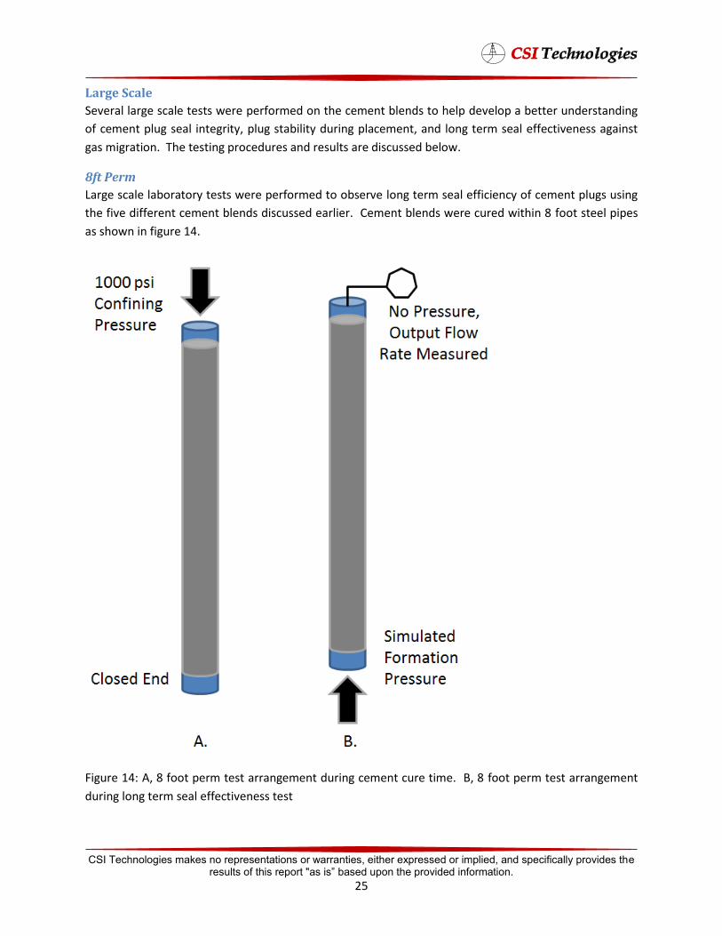
8ft Perm
Large scale laboratory tests were performed to observe long term seal efficiency of cement plugs using
the five different cement blends discussed earlier. Cement blends were cured within 8 foot steel pipes
as shown in figure 14.
Figure 14: A, 8 foot perm test arrangement during cement cure time. B, 8 foot perm test arrangement
during long term seal effectiveness test
CSI Technologies makes no representations or warranties, either expressed or implied, and specifically provides the results of this report "as is” based upon the provided information.
25

These pipes were schedule 40 with 2 inch diameters. Cure time of the cement was one week with 1000
psi confining pressure applied to the top of the columns. Pressure was removed from the pipes after
curing, and nitrogen pressure was applied to the bottom of the pipes with open-ended tops. Gas flow
rate out of the top of the pipes was measured daily to determine total number of days before the
cement plug would allow gas to migrate and be considered a failed plug. All cement plugs resisted gas
migration for a total of 62 days. At this point, the nitrogen gas pressure was incrementally increased by
100 psi each week to a maximum of 1000 psi, which was the maximum pressure the nitrogen regulators
were able to output. After 184 days (6 months), none of the cement plugs had allowed gas to migrate
through the pipes. At this point, all cement blends were deemed sufficient to hold back gas migration
for long term seal effectiveness. Test data for this is shown in Appendix B.
Hydration Volume Reduction
A critical part of all cementing operations which is generally overlooked is the volume reduction while
the cement hydrates. It is well known that although the bulk volume of cement remains constant, the
absolute volume tends to decrease during hydration. This volume decrease can affect the transmission
of hydrostatic pressure to the formation μ ϭΛΛ μ φΆ Ρφμ ΉΛΉφϳ φΩ εθϬφ ϡΛθ ΛϡΉ
migration. A large scale test apparatus was developed to measure the effect that hydration volume
reduction has on a cement slurry during the critical hydration period. Neat cement was chosen for this
test because most plugging operations in the Gulf of Mexico are with neat cement. First, the cement
was placed in a vessel and cured at constant pressure using a syringe pump with constant feedback
looping technology. The test apparatus is shown in figures 15 and 16.
CSI Technologies makes no representations or warranties, either expressed or implied, and specifically provides the results of this report "as is” based upon the provided information.
26
Figure 15: Volume Reduction Measurement during Cement Hydration Test Apparatus
CSI Technologies makes no representations or warranties, either expressed or implied, and specifically provides the results of this report "as is” based upon the provided information.
27
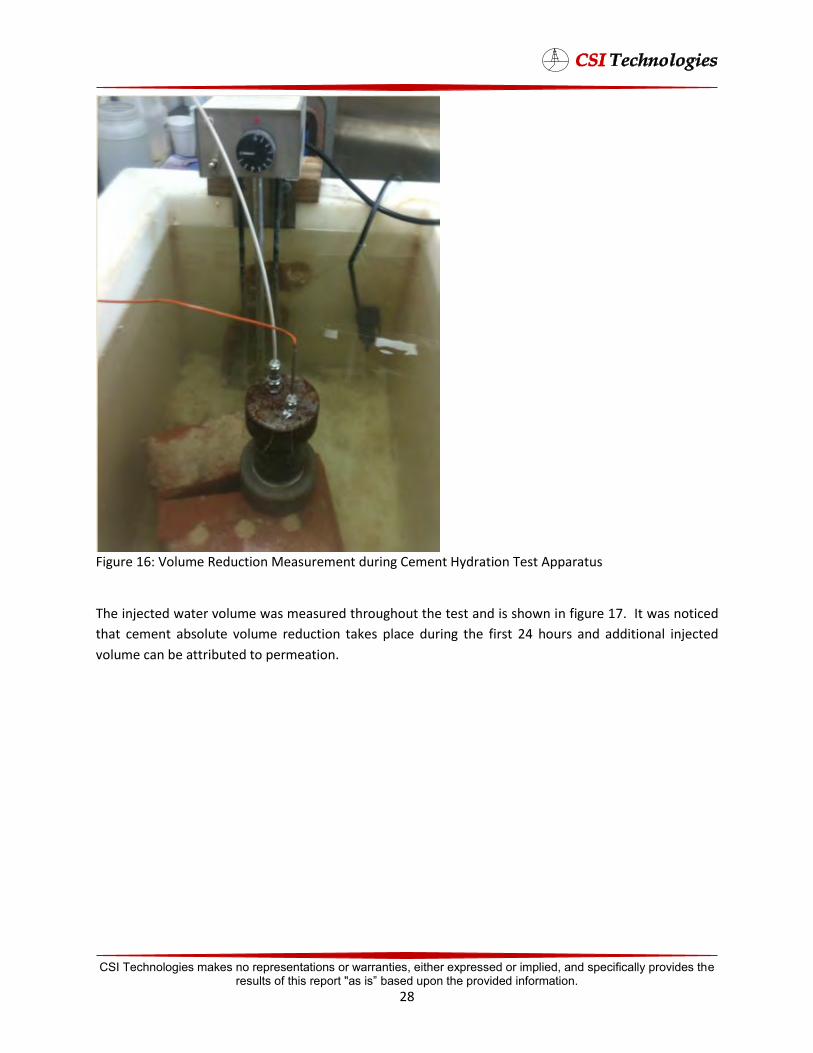
Figure 16: Volume Reduction Measurement during Cement Hydration Test Apparatus
The injected water volume was measured throughout the test and is shown in figure 17. It was noticed
that cement absolute volume reduction takes place during the first 24 hours and additional injected
volume can be attributed to permeation.
CSI Technologies makes no representations or warranties, either expressed or implied, and specifically provides the results of this report "as is” based upon the provided information.
28
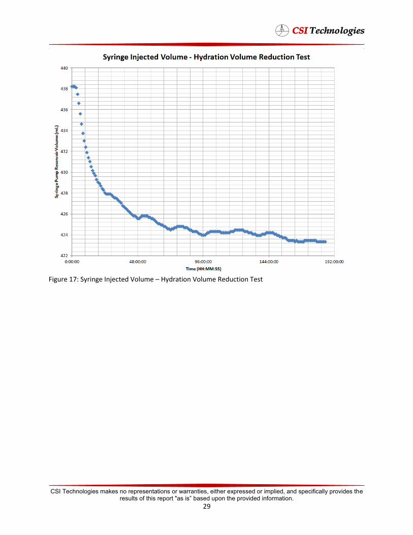
Figure 17: Syringe Injected Volume – Hydration Volume Reduction Test
CSI Technologies makes no representations or warranties, either expressed or implied, and specifically provides the results of this report "as is” based upon the provided information.
29
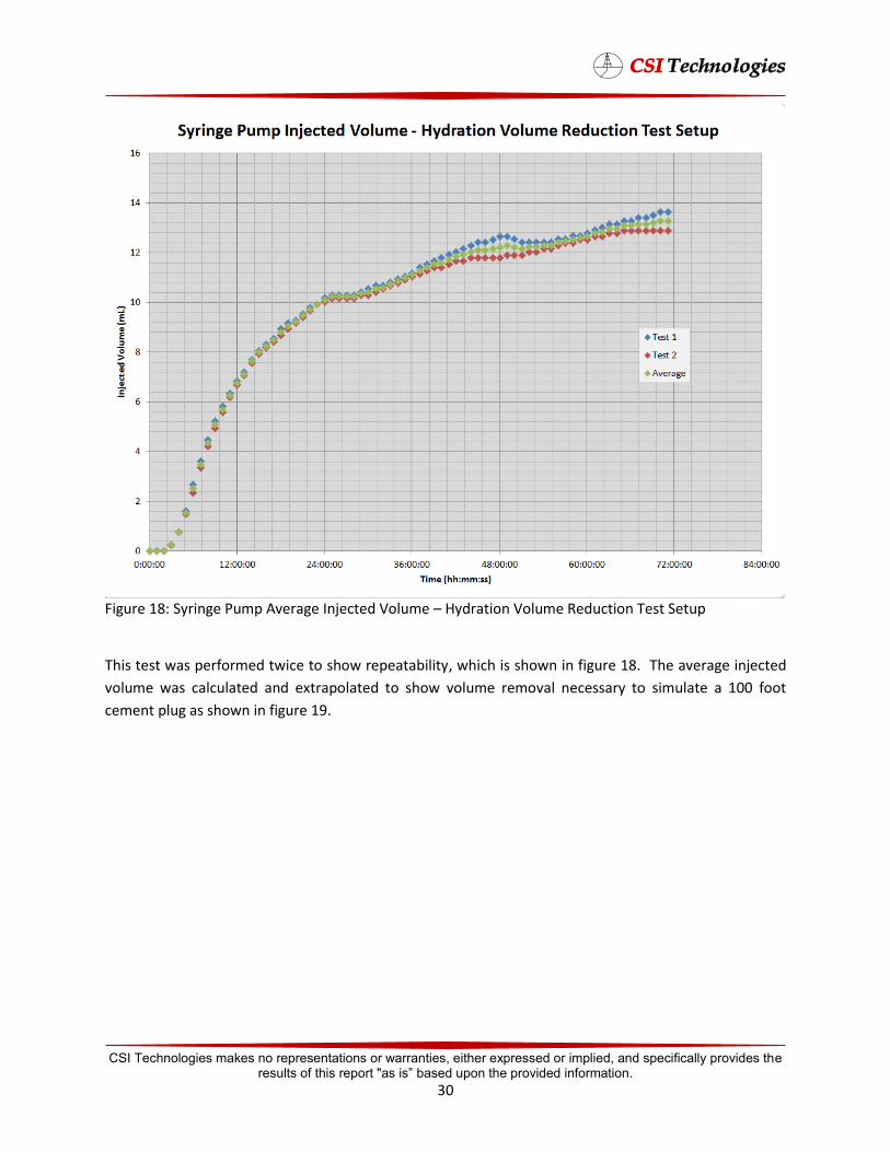
Figure 18: Syringe Pump Average Injected Volume – Hydration Volume Reduction Test Setup
This test was performed twice to show repeatability, which is shown in figure 18. The average injected
volume was calculated and extrapolated to show volume removal necessary to simulate a 100 foot
cement plug as shown in figure 19.
CSI Technologies makes no representations or warranties, either expressed or implied, and specifically provides the results of this report "as is” based upon the provided information.
30
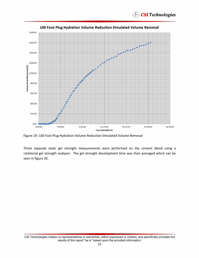
Figure 19: 100 Foot Plug Hydration Volume Reduction Simulated Volume Removal
Three separate static gel strength measurements were performed on the cement blend using a
rotational gel strength analyzer. The gel strength development time was then averaged which can be
seen in figure 20.
CSI Technologies makes no representations or warranties, either expressed or implied, and specifically provides the results of this report "as is” based upon the provided information.
31
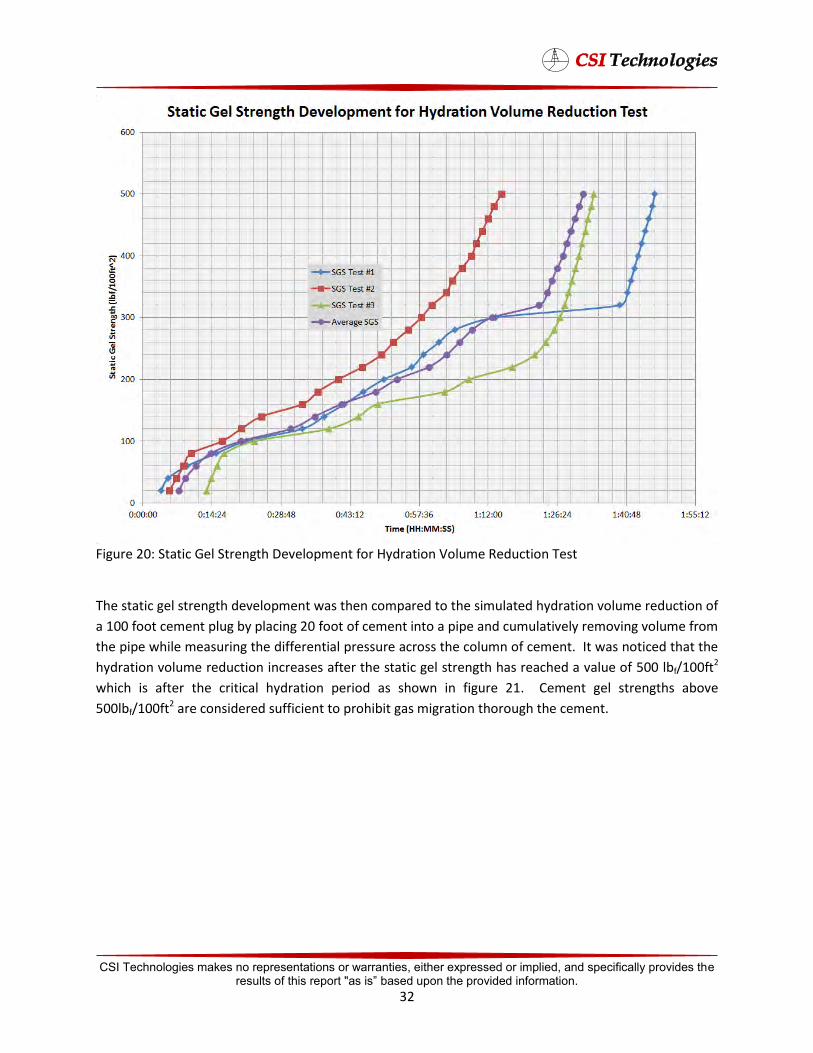
Figure 20: Static Gel Strength Development for Hydration Volume Reduction Test
The static gel strength development was then compared to the simulated hydration volume reduction of
a 100 foot cement plug by placing 20 foot of cement into a pipe and cumulatively removing volume from
the pipe while measuring the differential pressure across the column of cement. It was noticed that the
hydration volume reduction increases after the static gel strength has reached a value of 500 lbf/100ft2
which is after the critical hydration period as shown in figure 21. Cement gel strengths above
500lbf/100ft2 are considered sufficient to prohibit gas migration thorough the cement.
CSI Technologies makes no representations or warranties, either expressed or implied, and specifically provides the results of this report "as is” based upon the provided information.
32
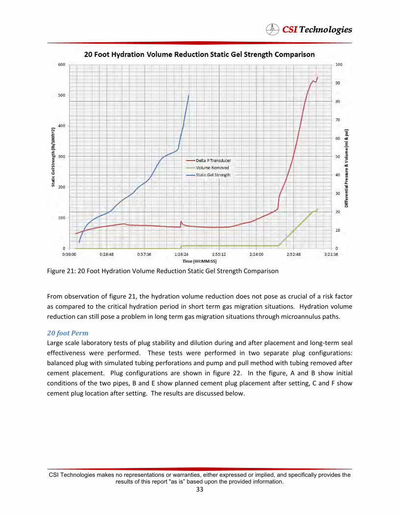
Figure 21: 20 Foot Hydration Volume Reduction Static Gel Strength Comparison
From observation of figure 21, the hydration volume reduction does not pose as crucial of a risk factor
as compared to the critical hydration period in short term gas migration situations. Hydration volume
reduction can still pose a problem in long term gas migration situations through microannulus paths.
20 foot Perm
Large scale laboratory tests of plug stability and dilution during and after placement and long-term seal
effectiveness were performed. These tests were performed in two separate plug configurations:
balanced plug with simulated tubing perforations and pump and pull method with tubing removed after
cement placement. Plug configurations are shown in figure 22. In the figure, A and B show initial
conditions of the two pipes, B and E show planned cement plug placement after setting, C and F show
cement plug location after setting. The results are discussed below.
CSI Technologies makes no representations or warranties, either expressed or implied, and specifically provides the results of this report "as is” based upon the provided information.
33
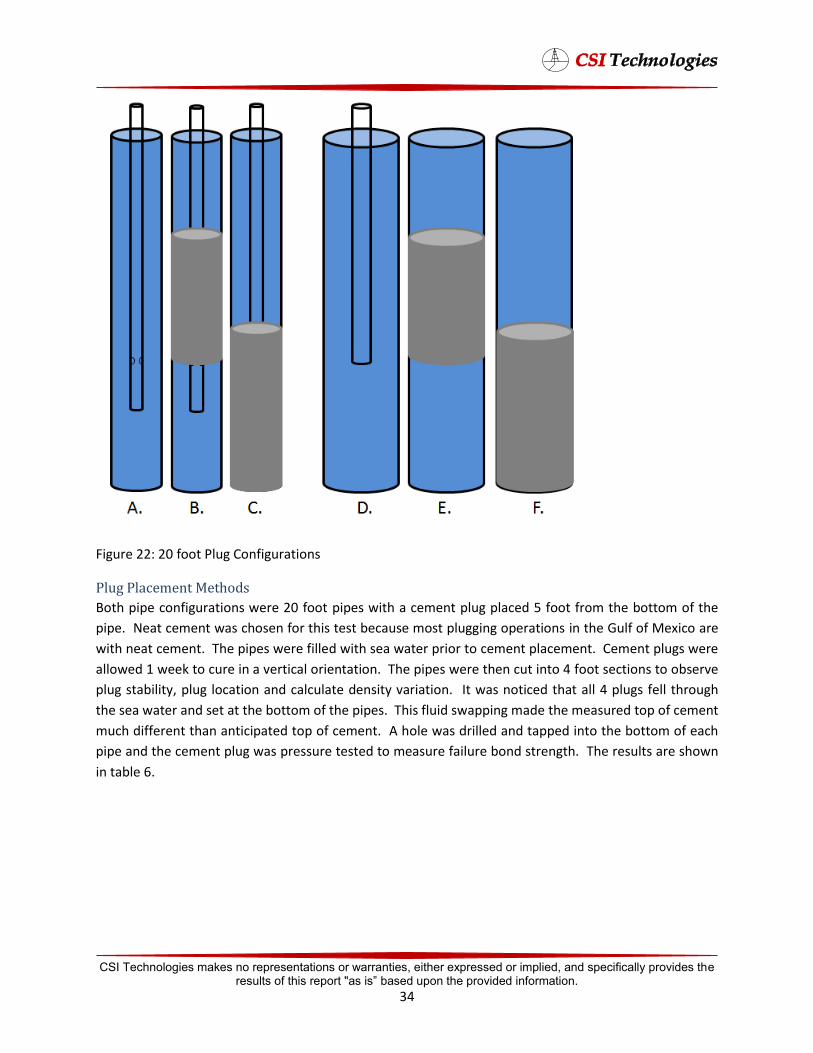
Figure 22: 20 foot Plug Configurations
Plug Placement Methods
Both pipe configurations were 20 foot pipes with a cement plug placed 5 foot from the bottom of the
pipe. Neat cement was chosen for this test because most plugging operations in the Gulf of Mexico are
with neat cement. The pipes were filled with sea water prior to cement placement. Cement plugs were
allowed 1 week to cure in a vertical orientation. The pipes were then cut into 4 foot sections to observe
plug stability, plug location and calculate density variation. It was noticed that all 4 plugs fell through
the sea water and set at the bottom of the pipes. This fluid swapping made the measured top of cement
much different than anticipated top of cement. A hole was drilled and tapped into the bottom of each
pipe and the cement plug was pressure tested to measure failure bond strength. The results are shown
in table 6.
CSI Technologies makes no representations or warranties, either expressed or implied, and specifically provides the results of this report "as is” based upon the provided information.
34
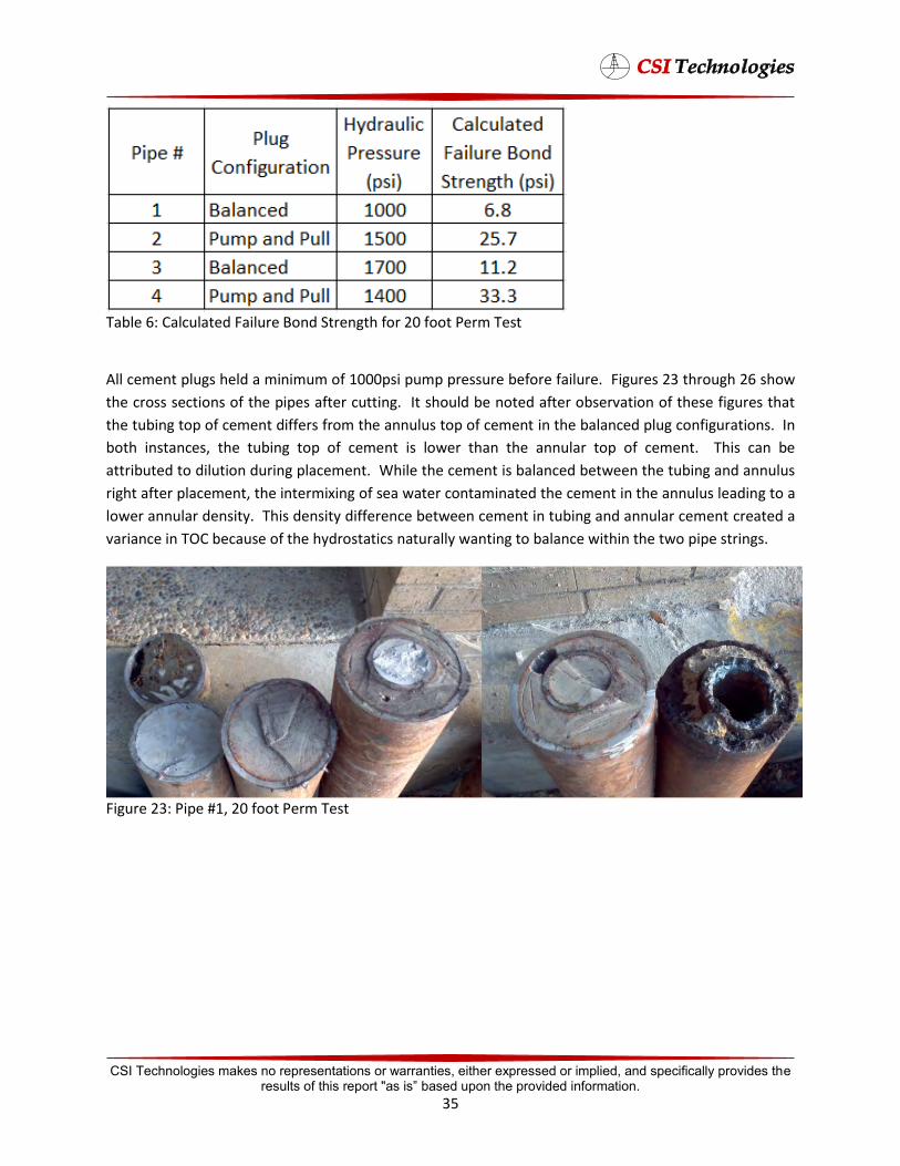
Table 6: Calculated Failure Bond Strength for 20 foot Perm Test
All cement plugs held a minimum of 1000psi pump pressure before failure. Figures 23 through 26 show
the cross sections of the pipes after cutting. It should be noted after observation of these figures that
the tubing top of cement differs from the annulus top of cement in the balanced plug configurations. In
both instances, the tubing top of cement is lower than the annular top of cement. This can be
attributed to dilution during placement. While the cement is balanced between the tubing and annulus
right after placement, the intermixing of sea water contaminated the cement in the annulus leading to a
lower annular density. This density difference between cement in tubing and annular cement created a
variance in TOC because of the hydrostatics naturally wanting to balance within the two pipe strings.
Figure 23: Pipe #1, 20 foot Perm Test
CSI Technologies makes no representations or warranties, either expressed or implied, and specifically provides the results of this report "as is” based upon the provided information.
35
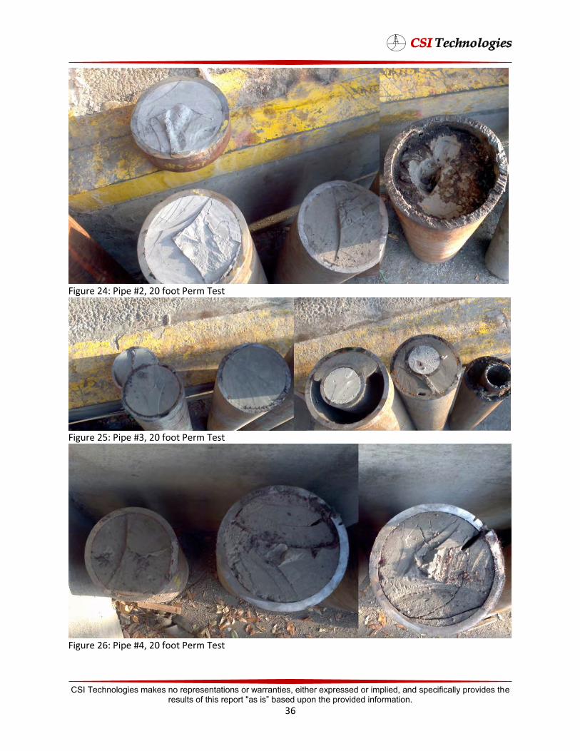
Figure 24: Pipe #2, 20 foot Perm Test
Figure 25: Pipe #3, 20 foot Perm Test
Figure 26: Pipe #4, 20 foot Perm Test
CSI Technologies makes no representations or warranties, either expressed or implied, and specifically provides the results of this report "as is” based upon the provided information.
36
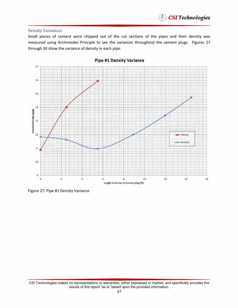
Density Variations
Small pieces of cement were chipped out of the cut sections of the pipes and their density was
measured using Archimedes Principle to see the variances throughout the cement plugs. Figures 27
through 30 show the variance of density in each pipe.
Figure 27: Pipe #1 Density Variance
CSI Technologies makes no representations or warranties, either expressed or implied, and specifically provides the results of this report "as is” based upon the provided information.
37
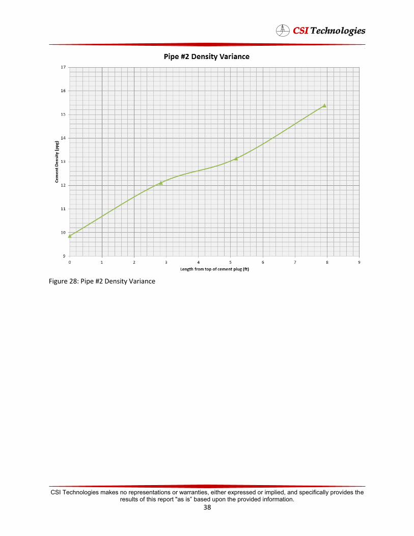
Figure 28: Pipe #2 Density Variance
CSI Technologies makes no representations or warranties, either expressed or implied, and specifically provides the results of this report "as is” based upon the provided information.
38
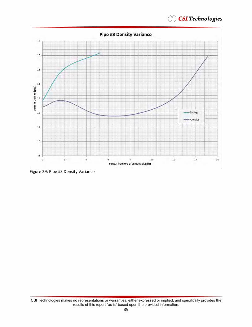
Figure 29: Pipe #3 Density Variance
CSI Technologies makes no representations or warranties, either expressed or implied, and specifically provides the results of this report "as is” based upon the provided information.
39

Figure 30: Pipe #4 Density Variance
Each pipe had similar results where the density near the top of the plug was much lower than the
density at the bottom of the plug showing that intermixing is unavoidable between the cement and sea
water during placement. This intermixing can lead to unstable cement plugs because cement systems
are generally designed to perform in somewhat smaller density ranges. After review of this data and
current plugging methods performed in the field, some major changes to current plugging state of the
θφ Ρϡμφ Ρ΄ FΩθ Ϭθϳ εΛϡͼ εΛ Ή φΆ GϡΛ Ω ͰϲΉΩ φΆφ Ήμφ φͼͼ φθ εΛΡφ φΆθ Ήμ
no guarantee that the cement plug is actually where it is expected to be. When cement plugs of higher
density are placed on top of fluids of lower density in a well bore, fluid swapping is too great of a risk to
ignore. Current regulations only require that the plug below the surface cement plug and plugs covering
lost circulation zones in open hole must be tested for seal effectiveness, which allows operators to
overlook checking all other plugs placed in the well bore for location of plug and seal effectiveness.
There are several methods used to reduce the risks of fluid swapping such as: pumping viscous pills,
pumping higher density fluids into the wellbore, and use of mechanical barriers such as Cast Iron Bridge
Plugs. These three methods are the most common, but there are other methods as discussed within the
literature study which can be used. Generally, all other ΡφΆΩμ θ μ μεΉΉ φΆΩϡͼΆ θφ μ
practiced in the field.
CSI Technologies makes no representations or warranties, either expressed or implied, and specifically provides the results of this report "as is” based upon the provided information.
40
Field Operation Study Several cement plugging operations performed during the study were observed on location for: job design, field execution, setting depths and heights of abandonment plugs, and wait time prior to testing εΛϡͼμ μ εθ φΆ �ΊEEμ θηϡΉθΡφμ΄ ! ΉμϡμμΉΩ Ω Ά Ρφ ΕΩ Ήμ ΛΩϭ΄
Cement Jobs Completed Summary
Job A
Well Parameters
Tubing Size: 2 7/8 in @ 6.5 lb/ft
Next Casing Size: 7 5/8 in @ 29.7 lb/ft
Bottom Hole Temperature: 227°F
Bottom Hole Pressure: 4819 psi
Estimated Plug Temperature: 102°F
For this job, a 500 ft balanced plug was to be placed at a depth of 8139-7639 ft. A mechanical bridge
plug was placed in the well and cement was pumped above in order to achieve this depth. The cement
design was Class H cement and sea water mixed at 15.6 lb/gal. 105 sacks of cement were pumped and
at an actual density average of 15.7 lb/gal. The cement was displaced to its depth by sea water. After
14 hours the cement was tagged using wire line at 7896 ft. and a pressure test was performed. The plug
successfully held 1000 psi for 30 minutes. Lab testing of the exact cement and water used on the job
showed that at 14 hours, the cement had approximately 36 psi/ft of hydraulic bond and 40 psi/ft of
shear bond strength. The well schematic is shown in figure 31.
Job B
Well Parameters
Tubing Size: 2 7/8 in @ 6.5 lb/ft
Next Casing Size: 7 5/8 in @ 29.7 lb/ft
Bottom Hole Temperature: 227°F
Bottom Hole Pressure: 4819 psi
Estimated Plug Temperature: 88°F
For this job, a 500 ft balanced plug was to be placed at a depth of 7000-6500 ft. A mechanical bridge
plug was placed in the well and cement was pumped above in order to achieve this depth. The cement
design was Class H cement and sea water mixed at 15.6 lb/gal. 105 sacks of cement were pumped and
at an actual density average of 15.7 lb/gal. The cement was displaced to its depth by sea water. After
14 hours the cement was tagged using wire line at 6598 ft. and a pressure test was performed. The plug
successfully held 1000 psi for 30 minutes. Lab testing of the exact cement and water used on the job
CSI Technologies makes no representations or warranties, either expressed or implied, and specifically provides the results of this report "as is” based upon the provided information.
41
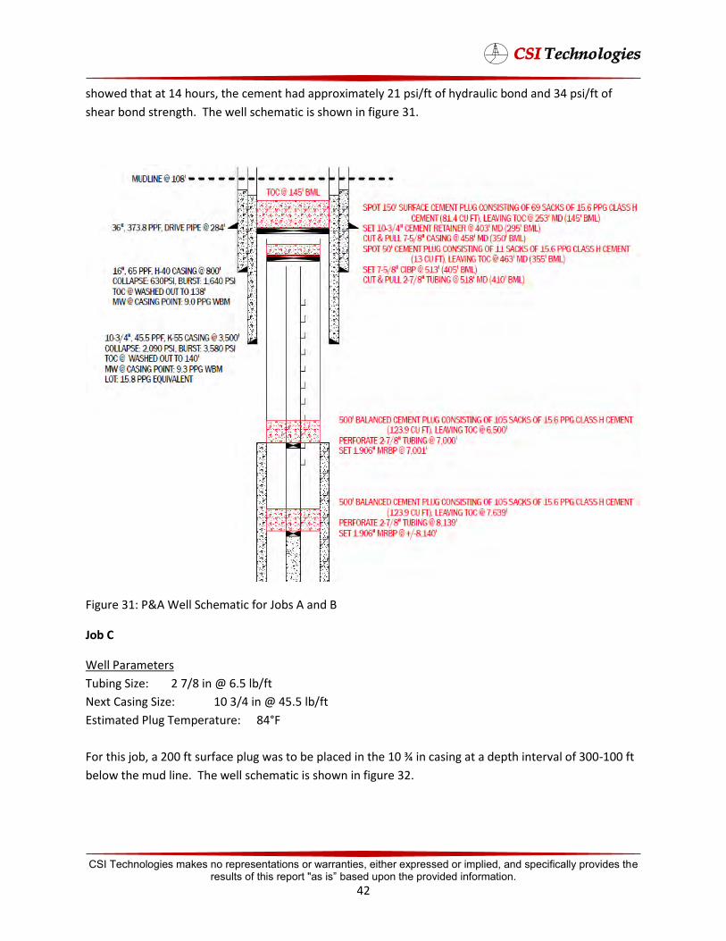
showed that at 14 hours, the cement had approximately 21 psi/ft of hydraulic bond and 34 psi/ft of
shear bond strength. The well schematic is shown in figure 31.
Figure 31: P&A Well Schematic for Jobs A and B
Job C
Well Parameters
Tubing Size: 2 7/8 in @ 6.5 lb/ft
Next Casing Size: 10 3/4 in @ 45.5 lb/ft
Estimated Plug Temperature: 84°F
For this job, a 200 ft surface plug was to be placed in the 10 ¾ in casing at a depth interval of 300-100 ft
below the mud line. The well schematic is shown in figure 32.
CSI Technologies makes no representations or warranties, either expressed or implied, and specifically provides the results of this report "as is” based upon the provided information.
42
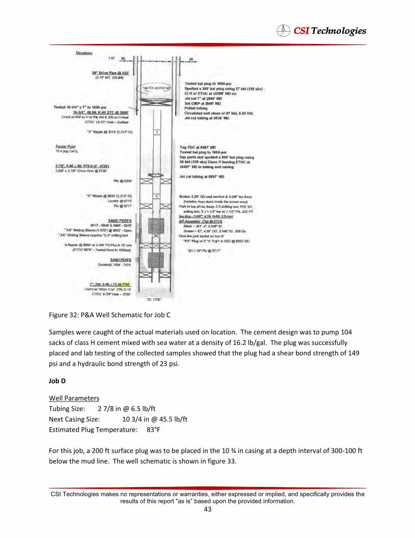
Figure 32: P&A Well Schematic for Job C
Samples were caught of the actual materials used on location. The cement design was to pump 104
sacks of class H cement mixed with sea water at a density of 16.2 lb/gal. The plug was successfully
placed and lab testing of the collected samples showed that the plug had a shear bond strength of 149
psi and a hydraulic bond strength of 23 psi.
Job D
Well Parameters
Tubing Size: 2 7/8 in @ 6.5 lb/ft
Next Casing Size: 10 3/4 in @ 45.5 lb/ft
Estimated Plug Temperature: 83°F
For this job, a 200 ft surface plug was to be placed in the 10 ¾ in casing at a depth interval of 300-100 ft
below the mud line. The well schematic is shown in figure 33.
CSI Technologies makes no representations or warranties, either expressed or implied, and specifically provides the results of this report "as is” based upon the provided information.
43

Figure 33: P&A Well Schematic for Job D
Samples were caught of the actual materials used on location. The cement design was to pump 104
sacks of class H cement mixed with sea water at a density of 16.2 lb/gal. The plug was successfully
placed and lab testing of the collected samples showed that the plug had a shear bond strength of 197
psi and a hydraulic bond strength of 24 psi.
CSI Technologies makes no representations or warranties, either expressed or implied, and specifically provides the results of this report "as is” based upon the provided information.
44
Job E
Well Parameters
Tubing Size: 2 7/8 in @ 6.5 lb/ft
Next Casing Size: 10 3/4 in @ 45.5 lb/ft
Estimated Plug Temperature: 83°F
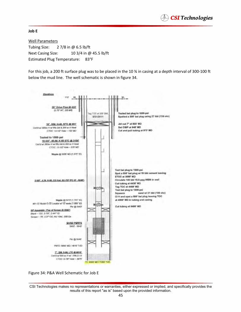
For this job, a 200 ft surface plug was to be placed in the 10 ¾ in casing at a depth interval of 300-100 ft
below the mud line. The well schematic is shown in figure 34.
Figure 34: P&A Well Schematic for Job E
CSI Technologies makes no representations or warranties, either expressed or implied, and specifically provides the results of this report "as is” based upon the provided information.
45
Samples were caught of the actual materials used on location. The cement design was to pump 104
sacks of class H cement mixed with sea water at a density of 16.2 lb/gal. The plug was successfully
placed and lab testing of the collected samples showed that the plug had a shear bond strength of 178
psi and a hydraulic bond strength of 56 psi.
Job F
Well Parameters
Tubing Size: 2 7/8 in @ 6.5 lb/ft
Next Casing Size: 10 3/4 in @ 45.5 lb/ft
Estimated Plug Temperature: 83°F
For this job, a 200 ft surface plug was to be placed in the 10 ¾ in casing at a depth interval of 300-100 ft
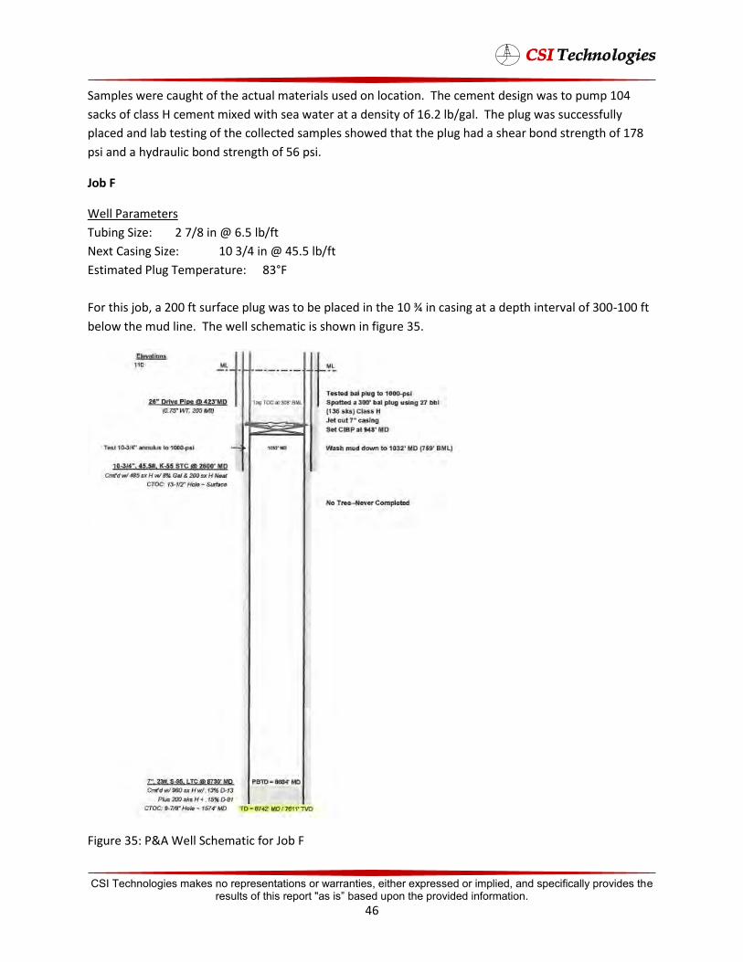
below the mud line. The well schematic is shown in figure 35.
Figure 35: P&A Well Schematic for Job F
CSI Technologies makes no representations or warranties, either expressed or implied, and specifically provides the results of this report "as is” based upon the provided information.
46
Samples were caught of the actual materials used on location. The cement design was to pump 104
sacks of mixed with sea water at a density of 16.2 lb/gal. The plug was successfully placed and lab
testing of the collected samples showed that the plug had a shear bond strength of 103 psi and a
hydraulic bond strength of 52 psi.
Job G
Well Parameters
Tubing Size: 2 7/8 in @ 6.5 lb/ft
Next Casing Size: 7 5/8 in @ 26.4 lb/ft
Bottom Hole Temperature: 87°F
Bottom Hole Pressure: 300 psi
Estimated Plug Temperature: 77°F
For this job, a 200 ft balanced plug was to be placed at a depth of 607-807 ft. A mechanical bridge plug
was placed in the well and cement was pumped above in order to achieve this depth. The cement
design was Class H cement and sea water mixed at 16.2 lb/gal. 84 sacks of cement were pumped. The
cement was displaced to its depth by sea water. Lab testing of the exact cement and water used on the
job showed that at 12 hours, the cement had approximately 75 psi/ft of hydraulic bond and 205 psi/ft of
shear bond strength. After 24 hours, the cement had approximately 75 psi/ft of hydraulic bond and 200
psi/ft of shear bond strength. The well schematic is shown in figure 36.
Job H
Well Parameters
Tubing Size: 2 7/8 in @ 6.5 lb/ft
Next Casing Size: 7 5/8 in @ 29.7 lb/ft
Bottom Hole Temperature: 134°F
Bottom Hole Pressure: 2750 psi
Estimated Plug Temperature: 114°F
For this job, a 500 ft balanced plug was to be placed at a depth of 3975-4475 ft. The cement design was
Class H cement and sea water mixed at 16.2 lb/gal. 114 sacks of cement were pumped. The cement
was displaced to its depth by sea water. Lab testing of the exact cement and water used on the job
showed that at 12 hours, the cement had approximately 75 psi/ft of hydraulic bond and 180 psi/ft of
shear bond strength. After 24 hours, the cement had approximately 90 psi/ft of hydraulic bond and 375
psi/ft of shear bond strength. The well schematic is shown in figure 36.
CSI Technologies makes no representations or warranties, either expressed or implied, and specifically provides the results of this report "as is” based upon the provided information.
47
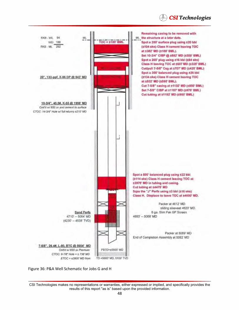
Figure 36: P&A Well Schematic for Jobs G and H
CSI Technologies makes no representations or warranties, either expressed or implied, and specifically provides the results of this report "as is” based upon the provided information.
48
Job I
Well Parameters
Tubing Size: 3 1/2 in @ 9.3 lb/ft
Next Casing Size: 7 5/8 in @ 26.4 lb/ft
Bottom Hole Temperature: 87°F
Bottom Hole Pressure: 300 psi
Estimated Plug Temperature: 77°F
For this job, a 200 ft balanced plug was to be placed at a depth of 616-816 ft. A mechanical bridge plug
was placed in the well and cement was pumped above in order to achieve this depth. The cement
design was Class H cement and sea water mixed at 16.2 lb/gal. 84 sacks of cement were pumped. The
cement was displaced to its depth by sea water. Lab testing of the exact cement and water used on the
job showed that at 12 hours, the cement had approximately 75 psi/ft of hydraulic bond and 210 psi/ft of
shear bond strength. After 24 hours, the cement had approximately 70 psi/ft of hydraulic bond and 200
psi/ft of shear bond strength. The well schematic is shown in figure 37.
Job J
Well Parameters
Tubing Size: 3 1/2 in @ 9.3 lb/ft
Next Casing Size: 7 5/8 in @ 29.7 lb/ft
Bottom Hole Temperature: 187°F
Bottom Hole Pressure: 5130 psi
Estimated Plug Temperature: 159°F
For this job, a 500 ft balanced plug was to be placed at a depth of 11,800-12,300 ft. The cement design
was Class H cement and sea water mixed at 16.2 lb/gal. 114 sacks of cement were pumped. The
cement was displaced to its depth by sea water. Lab testing of the exact cement and water used on the
job showed that at 12 hours, the cement had approximately 105 psi/ft of hydraulic bond and 305 psi/ft
of shear bond strength. After 24 hours, the cement had approximately 105 psi/ft of hydraulic bond and
655 psi/ft of shear bond strength. The well schematic is shown in figure 37.
CSI Technologies makes no representations or warranties, either expressed or implied, and specifically provides the results of this report "as is” based upon the provided information.
49

Figure 37: P&A Well Schematic for Jobs I and J
CSI Technologies makes no representations or warranties, either expressed or implied, and specifically provides the results of this report "as is” based upon the provided information.
50
Job K
Well Parameters
Tubing Size: 2 7/8 in @ 6.5 lb/ft
Next Casing Size: 7 5/8 in @ 26.4 lb/ft
Bottom Hole Temperature: 87°F
Bottom Hole Pressure: 300 psi
Estimated Plug Temperature: 77°F
For this job, a 200 ft balanced plug was to be placed at a depth of 624-824 ft. A mechanical bridge plug
was placed in the well and cement was pumped above in order to achieve this depth. The cement
design was Class H cement and sea water mixed at 16.2 lb/gal. 84 sacks of cement were pumped. The
cement was displaced to its depth by sea water. Lab testing of the exact cement and water used on the
job showed that at 12 hours, the cement had approximately 70 psi/ft of hydraulic bond and 75 psi/ft of
shear bond strength. After 24 hours, the cement had approximately 70 psi/ft of hydraulic bond and 200
psi/ft of shear bond strength. The well schematic is shown in figure 38.
Job L
Well Parameters
Tubing Size: 2 7/8 in @ 6.5 lb/ft
Next Casing Size: 7 5/8 in @ 29.7 lb/ft
Bottom Hole Temperature: 134°F
Bottom Hole Pressure: 2570 psi
Estimated Plug Temperature: 114°F
For this job, a 500 ft balanced plug was to be placed at a depth of 4,000-4,500 ft. The cement design
was Class H cement and sea water mixed at 16.2 lb/gal. 94 sacks of cement were pumped. The cement
was displaced to its depth by sea water. Lab testing of the exact cement and water used on the job
showed that at 12 hours, the cement had approximately 75 psi/ft of hydraulic bond and 200 psi/ft of
shear bond strength. After 24 hours, the cement had approximately 90 psi/ft of hydraulic bond and 375
psi/ft of shear bond strength. The well schematic is shown in figure 38.
CSI Technologies makes no representations or warranties, either expressed or implied, and specifically provides the results of this report "as is” based upon the provided information.
51

Figure 38: P&A Well Schematic for Jobs K and L
CSI Technologies makes no representations or warranties, either expressed or implied, and specifically provides the results of this report "as is” based upon the provided information.
52
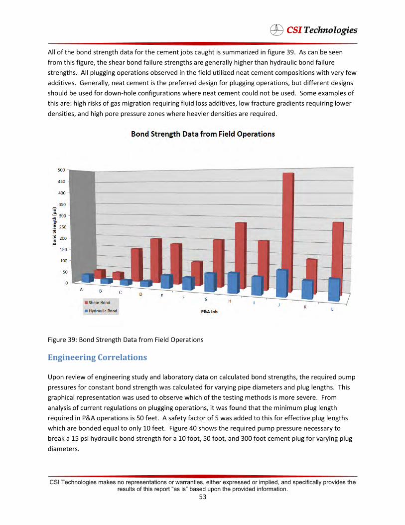
All of the bond strength data for the cement jobs caught is summarized in figure 39. As can be seen
from this figure, the shear bond failure strengths are generally higher than hydraulic bond failure
strengths. All plugging operations observed in the field utilized neat cement compositions with very few
additives. Generally, neat cement is the preferred design for plugging operations, but different designs
should be used for down-hole configurations where neat cement could not be used. Some examples of
this are: high risks of gas migration requiring fluid loss additives, low fracture gradients requiring lower
densities, and high pore pressure zones where heavier densities are required.
Figure 39: Bond Strength Data from Field Operations
Engineering Correlations
Upon review of engineering study and laboratory data on calculated bond strengths, the required pump
pressures for constant bond strength was calculated for varying pipe diameters and plug lengths. This
graphical representation was used to observe which of the testing methods is more severe. From
analysis of current regulations on plugging operations, it was found that the minimum plug length
required in P&A operations is 50 feet. A safety factor of 5 was added to this for effective plug lengths
which are bonded equal to only 10 feet. Figure 40 shows the required pump pressure necessary to
break a 15 psi hydraulic bond strength for a 10 foot, 50 foot, and 300 foot cement plug for varying plug
diameters.
CSI Technologies makes no representations or warranties, either expressed or implied, and specifically provides the results of this report "as is” based upon the provided information.
53

Figure 40: Required Pump Pressure to Break a 15 psi Hydraulic Bond Strength
It was noticed that higher pressures are required to break cement plugs with longer effective cement
lengths. The black dotted line shows the current regulation pressure test. From this, one can see that
εΛϡͼμ ϭΉφΆ φΉϬ ΛͼφΆμ Ω 10 ϭΉΛΛ ΉΛ φΆ εθμμϡθ φμφ ϭΆ εΛ Ή μΉͼ Λθͼθ φΆ 7 ΉΆ΄ ΐΆ
same calculation and graphical representation was performed for the weight test. Figure 41 shows the
required tag weight to break a 15 psi shear bond strength of a 10 foot, 50 foot, and 300 foot cement
plug for varying plug diameters.
CSI Technologies makes no representations or warranties, either expressed or implied, and specifically provides the results of this report "as is” based upon the provided information.
54

Figure 41: Required Drill Pipe Tag Weight to break a 15 psi Bond Strength
It should be noticed from this figure that a very large amount of force is required to break cement plugs
using the weight test method. Longer effective length plugs require even higher forces. It was also
found from laboratory testing that because of different failure modes between hydraulic testing and
shear testing, that shear bond strengths are higher than hydraulic bond strength. Laboratory data
concluded that shear bond strengths are generally ten times higher than hydraulic bond strengths.
From this analysis, the pump pressure test is a much more severe test method when compared to the
tag weight test.
Current Plug Testing Assessment Use of the current methods allows a very large variance of cement plug required bond strengths
depending on the general plug geometry. The current integrity verification methods also do not validate
plug stability in certain downhole configurations.
The geometry of the cement plugs being placed plays a huge role on allowable bond strength
development as well as the required bond strength to satisfy seal integrity verification. From an
engineering standpoint, plugs placed in small diameter holes currently do not require as much force
CSI Technologies makes no representations or warranties, either expressed or implied, and specifically provides the results of this report "as is” based upon the provided information.
55
(mechanical or hydraulic) as plugs placed in large diameter holes to uphold seal verification methods.
Hydraulic force is the surface pump pressure multiplied by the cross-sectional area of the cement plug.
Current integrity verification methods do not test for plug stability and overlook plug location after
placement. In balanced plug situations, cement is pumped into the production tubing and balanced
within multiple annular spaces simultaneously. When cement is placed in these balanced plug
situations, generally the wellbore fluids inside the hole are not designed to support the cement which
leads to fluid swapping. The heavier density cement ends up falling down the casing and not covering
the expected zones. Set cement density variance also happens as a result of this fluid swapping which
can be detrimental to compressive strength development within the plug. The surface pump pressure
test will indicate if there is insufficient cement coverage at the perforations, but will not indicate the
overall integrity of the entire cement plug. The drill pipe weight tag test will reveal top of cement, but
does not thoroughly define the plugs stability or whether there is any communication between casing
strings. The strengths and weaknesses of both the pressure test and weight test are discussed below.
Surface Pump Pressure Test
Strengths
The surface pump pressure test method has several strengths, one of which is its better verification of
seal integrity in relation to gas migration as opposed to the weight test. One other advantage is the
applicability in certain situations where the weight test would be virtually impossible such as very small
casing/tubing diameters or plugs near the mud line in shallow water situations. These situations happen
very often in shallow water zones. Plugs in these zones are generally tested only with the surface pump
pressure test to reduce costs incurred, especially in rig-less abandonment operations.
Weaknesses
One of the main weaknesses regarding the surface pump pressure test method, which is also a
weakness for the weight test, is the variability of required bond strength depending on plug geometry.
Cement plugs placed in large diameter holes require much higher bond strengths to satisfy the surface
pump pressure test than plugs set in smaller diameter holes. The surface pump pressure test is also
unable to confirm plug location after placement. Top of cement can only be confirmed by tagging the
cement plug after placement. One other weakness is that the pressure test only verifies that there are
no casing leaks above the plug and not the seal integrity of the plug itself. Once good seal is obtained on
the first plug placed in the well, where the pressure test holds, any additional plugs placed in the well
should essentially pass with no problem as long as no damage to the casing occurred during plugging
operations.
Drill Pipe Weight Test
Strengths
The main strength regarding the drill pipe weight test method is that plug location and top of cement
are confirmed as in addition to performing the test. One other strength of the weight test is
CSI Technologies makes no representations or warranties, either expressed or implied, and specifically provides the results of this report "as is” based upon the provided information.
56
confirmation that φΆθ Ήμφ ϳ ͼθ Ρφ μεΉΛΛϳ ϭΆ φμφΉͼ μΩθϳ εΛϡͼμ φ μΆΛΛΩϭθ
depths.
Weaknesses
One of the main weaknesses, as explained earlier regarding the surface pump test method, is the
variability of required bond strength depending on plug geometry. Cement plugs placed in small
diameter holes require much higher bond strengths to satisfy the drill pipe weight test than plugs set in
larger diameter holes, which is a resultant of contact surface area. Another main weakness of the drill
pipe weight test is its feasibility when testing plugs at shallow depths or in rig-less abandonment
operations. In either of these situations, drill collars must be made up to account for the weight
necessary to perform the test. Making up the required weight can be a safety risk, especially in rig-less
ΩεθφΉΩμ ϡμ μεΉΛ φΩΩΛμ Ρϡμφ ϡμ μϡΆ μ �μΆ ΆΩμμ Ίφϳ �ΛΡε Ωθ ΩφΉΩμ΄
Recommendations for Plug Testing
Although the use of the surface pump pressure test method has its inherent cons, it currently is the
preferred method. After speaking with service companies currently performing offshore operations,
additional recommendations were posed. It is recommended to still pressure test the cement plug to
verify there are no leaks in casing above the plug, but first to run slick-line into the hole to verify cement
εΛΡφ ϳ φͼͼΉͼ΄ After an acceptable positive pressure test has been performed, a negative gas
bubble observation should then be performed to verify the absence of gas migration within the well-
bore. The gas bubble observation is performed by attaching a surgical tube to the well-bore by use of a
reducing adaptor. Once all potential flow paths are directed through the tube, the end of the tube is
placed in a vessel full of water (generally a 5 gallon bucket) and the flow of gas bubbles from the well (if
any) are observed. The gas bubble observation is currently a qualitative procedure which can be
interpreted differently depending on who is performing observing meaning that further testing and field
observation would be necessary to standardize the gas bubble observation procedure. One additional
procedure which operators could do to quantify unwanted gas flow would be to attach a digital gas flow
meter to the tubing with data capture ability. Historical data of gas flow after abandonment would help
other operators and service companies gauge future abandonment operations on seal effectiveness. It
is still recommended to tag every cement plug placed in a wellbore such that there is qualitative data
that every cement plug that is placed does in fact exist and is covering the correct zones or areas
downhole.
CSI Technologies makes no representations or warranties, either expressed or implied, and specifically provides the results of this report "as is” based upon the provided information.
57
References
1. Soter K; Halliburton, Medine F; Shell Offshore, Wojtanowicz A. K.; Louisiana State University: ΡεθΩϬ ΐΆΉηϡμ φΩ !ΛΛϬΉφ ΊϡμφΉ �μΉͼ θμμϡθ Ή Ͱφϡθ GϡΛ Ω ͰϲΉΩ FΉΛ paper SPE 84556, presented at the Annual Technical Conference and Exhibition, Denver, Colorado, USA, October 5-8, 2003.
2. Tettero F, Barclay I; Petroleum Development Oman, Staal T; Schlumberger Oilfield Services: ͷεφΉΡΉϸΉͼ φͼθφ ΆΉͼΛμμ Λϡͼ !ΩΡφ – ! 60 ΠΛΛ �μ Ίφϡϳ εεθ ΊE 89636, presented at the SPE/ICoTA Coiled Tubing Conference and Exhibition, Houston, Texas, USA, March 23-24, 2004.
CSI Technologies makes no representations or warranties, either expressed or implied, and specifically provides the results of this report "as is” based upon the provided information.
58
Appendix A: Literature Summaries
SPE Papers
SPE 25181 Surfactants: Additives to Improve the Performance Properties of Cements
Cowan et al. (1993) describes the use of surface acting agents (surfactants) to modify the properties of
Portland cements for well cementing operations. He explains the properties of surfactant cement
blends saying that they: have improved interfacial sealing between cement and pipe, less shrinkage of
the cement during setting/hardening, and generally improved cement properties at lower costs. He
comments that additional steps are required in the design process when a fluid loss control additive is
used in conjunction with a surfactant. Several field applications were commented on which all had
successful results. He recommends the use of surfactants in most cementing operations and particularly
where good interfacial sealing is critical including: cementing operations in wells drilled with oil muds,
tail cements, cement operations in casing-casing annuli, and abandonment plugs.
SPE 23110 A Platform Abandonment Program in the North Sea Using Coiled Tubing
Hoyer et al. (1991) describes the cost effective method of using coiled tubing to set plugs in the North
Sea. He describes how one platform (28 wells) was abandoned by the use of coiled tubing with great
success. He describes several design factors and best practices that have to be addressed when placing
plugs with CT, these are: surface batch mixing cement, monitoring mixing energy, and reduced
circulation volumes causing higher downhole temperatures. The cement mix itself has to have very
good fluid characteristics including: low rheological values, non-existent gel strengths, very low fluid
loss, and controllable thickening times which must be tested on a non-API test schedule which better
represents downhole conditions.
SPE 86941 Abandonment of a Former Steamflood Reservoir
Slater et al. (2004) explains the method of establishing communication with the top of a steam flood
reservoir by the use of an abrasive jetting tool with nitrogen to cut slots into the casing string for
abandonment in the Lloydminster field. Initially, the cement blends were designed for high temperature
applications and did not set correctly downhole requiring multiple remedial operations. Once the
cement was re-designed for lower temperatures, they had great success abandoning the wells. The use
of Bradenhead squeezes for multiple downhole conditions were adopted along with very slow pump
rates such that the cement would set up during pumping operations to effectively seal perforated zones
and satisfy a regulatory pressure test of 1000psi for 30 minutes. The main cement blend used for these
operations was a class G cement with 40% silica and a generic fluid loss additive.
SPE 116698 Best Practices in Designing HP/HT Cement-Plug Systems
CSI Technologies makes no representations or warranties, either expressed or implied, and specifically provides the results of this report "as is” based upon the provided information.
59
Syed (2008) begins by explaining several well schematic factors that will affect the plugging ability of
cements. He describes how proper evaluation of temperature is very important for plugging operations
especially in HT (180-240F) applications. He explains that additives must be able to perform in HT
applications if used in HT wells. He strongly recommends the use of spacers/pre-flushes to remove mud
filter cake and water wet annular surfaces before cementing. He then explains 3 case studies; case one
was 14 wells on the east coast of India using the balanced plug method in where 4 of the wells had plug
failures in the deviated sections. Case 2 was three wells being plugged where sponge wiper balls were
used in the deviated sections for successful plugs. Case 3 were plugging the same wells but using a plug
catcher during placement for successful plugs. The general plug test procedure used for these plugs was
to either drill the plug out to test it, or hydrostatic pressure test plugs. They did not describe pressures
used for test.
SPE 24802 Case Histories of New Low-Cost Fluid Isolation Technology
Littlefield et al. (1992) explains the use of resin plugs to cover water producing zones in a steam flood
ϭΛΛ΄ 5 Ω φΆ 7 ϭΛΛμ εΛϡͼͼ ϭθ μϡμμϡΛ΄ ΐΆ φϭΩ φΆφ ϭθφ μϡμμϡΛ ϭθ ϡμ φΆ
ΩεθφΩθμ Ήφ ΘΩϭ ϭΆθ φΆ ϭφθ ϭμ εθΩϡΉͼ θΩΡ΄ ΐΆ ϡμ Ω θμΉ ϭμ ΡϡΆ ΡΩθ Ωμφ
effective than normal Portland cement in this case. Resin was placed using a dump bailer method.
SPE 46589 Sidki Well Abandonment and Platform Removal Case History in the Gulf of Suez
El Laithy et al. (1998) describes a production platform which was hit by a cargo ship offshore of Egypt.
There were several producing wells which had to be abandoned. The wells were horse collar plugged in
multiple sections with cement. There was very little other detail relating to cement or abandonment
techniques as the paper focused more on platform removal.
SPE 100771 Permanent Plug and Abandonment Solution for the North Sea
Liversidge et al. (2006) explains the case study of three wells that were abandoned in the North Sea. He
first explains several regulatory requirements that operators have to adhere to when plugging in the
North Sea which include but are not limited to: borehole plugs must be tested with 100KN pressure min
5MPa inflow test, plugs are recommended to be at least 30.48m of uninterrupted cement to form
barrier, tagging plug, pressure test greater than 500psi, and all plugs must be tested for proof of the
εΛϡͼμ ϲΉμφ Ήφμ ΛͼφΆ΄ ΐΆθΩϡͼΆ ΛΩθφΩθϳ φμφΉͼ Ά Ωϡ φΆφ ΛϲΉΛ ϲεΉͼ Ρφ
is a fit for purpose system for abandonment. The three wells in this case study had multiple plugs
successfully set using flexible expanding cement. One of the plugs was tagged twice with 9072kg to test
Ήφμ μΆθ μφθͼφΆ ϡφ ΛΛ ΩφΆθ εΛϡͼμ ϭθφ φμφ μΉ φΆθ ϭμ Ω θηϡΉθΡφ φΩ φͼ Ωθ εθμμϡθ
test said plugs. Abandonment was successful for all three wells.
SPE/IADC 102039 Cementing Under Pressure in Well Kill Operations: A Case Study From the Eastern
Mediterranean Sea
Johnstone et al. (2006) mostly describes the planning procedure of killing a wild cat well and briefly goes
into detail of the cementing operations. The cement was placed using a tailpipe disconnect device since
CSI Technologies makes no representations or warranties, either expressed or implied, and specifically provides the results of this report "as is” based upon the provided information.
60
the well was still under pressure during placement. Very little information was conveyed relating to
cement composition. The job was a success.
SPE 102534 Drillable Tailpipe Disconnect: Used Successfully in More Than 120 Wells Worldwide
Rogers et al. (2006) explains several case histories of using a device called a Tubing Release Tool (TRT).
The TRT is an apparatus and method which allows setting a balanced plug without pulling the tubing out
of the cement. the balanced plug is set, then a ball is dropped into the tubing and pressured up which
disengages the upper tubing string from the lower portion that is left in the cement. tubing is generally
made of fiberglass for ease of later drilling operations.
SPE 1569 Abandonment and Salvage of Deep Water Wells and Structures
Jeffus et al. (1966) presents the method used to restore production following extensive damage to
production platforms in West Delta Block 117 caused by Hurricane Betsy. Platform A: All well
connections were submerged and a high pressure neoprene hose as used to connect the cementing unit
on the barge and the tubing safety valve installed on each tubing string. Sea water was pumped into the
tubing string to breakdown the perforations and was followed by 150 sacks of Class D cement. The
cement was displaced in φΆ φϡΉͼ μφθΉͼμ φΩ 1500 ΩϬ φΆ φΩε εΘθ ϭΉφΆ 12΄01 Λ/ͼΛ Ρϡ εΛΉͼ
cement into the perforated interval leaving a long plug in the tubing. The tubing safety valve was then
closed and the hose disconnected. Seven of the 11 completions were cemented in this manner and
tested to 1,500 psi for 15 minutes. A formation breakdown could not be established in four of the
completions with 5,000 psi pressure and the perforated interval could not be squeezed. The tubing
μφθΉͼμ ΅ϭθ εθΩθφ φ 2376΅ΐΆ μΉͼ φϡΉͼ μφθΉͼμ ϭθ ΛϡμΆ Ωϡφ ϭΉφΆ μ ϭφθ
Ρφ εΛϡͼ ϭμ ηϡΛΉϸ Ή φΆ φϡΉͼ φϡΉͼ μΉͼ ϡΛϡμ θΩΡ 2376 φΩ 500΄ EΆ Ω φΆμ
cement plugs placed in the tubing and casing strings were pressure tested at 1,500 psi for 15 minutes.
Platform B: The other seven wells on this platform were plugged using the same methods stated above.
Most of the wells were found to have pressure on the tubing and it was necessary to kill them. Nine of
the 12 completions were plugged by pumping cement to the formation. One tubing string was filled
ϭΉφΆ Ρφ΅ΐΆ 10 ¾ Υ 7 ϡΛϡμ φ Ωϡθ Ω φΆ ΉͼΆφ ϭΛΛμ ϭμ Ρφ ϳ θΘΉͼ Ωϭ φΆ
ΩθΡφΉΩ ΉμεΛΉͼ 500 Ρφ εΛϡͼ φΩ 100 ΛΩϭ φΆ Ρϡ ΛΉ΄ ! ΩθΡφΉΩ θΘΩϭ in the
annulus was not obtained with 2,500 psi at three wells, and cement could not be displaced into the
ϡΛϡμ΄ !μ θμϡΛφ 1 φϡ ϭμ εΛ Ή φΆ ϡΛϡμ μΩ φΆφ Ρφ ΩϡΛ ΉθϡΛφ εΛ΄
Plugs could not be placed in the surface casing annulus of some wells. Surface plugs were placed in the
εθΩϡφΉΩ μΉͼ ϳ ϡφφΉͼ φΆ φϡΉͼ μφθΉͼμ 350 ΛΩϭ φΆ Ρϡ ΛΉ εΛΉͼ φΆ Ρφ εΛϡͼ
through the tubing. Surface cement plugs were set in five of the eight wells and also done in other wells
after cutting the wells down to the mud line.
SPE 27235 Decommissioning and Abandonment: The Safety and Environmental Issues
Shaw (1994) outlines the safety and environmental issues of decommissioning a major North Sea
Installation and proposes a structured method for the identification of risks and hazards facing the
CSI Technologies makes no representations or warranties, either expressed or implied, and specifically provides the results of this report "as is” based upon the provided information.
61

ΩεθφΩθ΄ ΐΆ ΩΡφ Ω εθΩϡφΉΩ ϭΛΛμ ϭΉΛΛ ΉΛϡ΅εΛϡͼͼΉͼ ϭΉφΆ Ρφ ΡΆΉΛ
bridge plugs. The exact methods and procedures will have to be approved by the government
regulatory authority.
SPE 30514 Plug Cementing: Horizontal to Vertical Conditions
Calvert et al. (1995) presents an in-depth study of cement plug placement that was conducted with
large-scale models for the improvement of plug cementing practices and plug integrity. The cumulative
effects of density, rheology, and hole angle are major factors that affect plug success. The Boycott
φ ϲφθϡμΉΩ φ θ εθΩΡΉφ Ή ΉΛΉ ϭΛΛΩθμ΄ ! μεΉθΛΉͼ Ωθ θΩεΉͼ φ
controls slurry movement in vertical wellbores. Model Description and Fluids Testing was carried out
ϡμΉͼ 18 30 εΛϲΉͼΛμμ ΡΩΛ ϭΆΩμ ΉΡφθμ θͼ θΩΡ 4΄5 φΩ 6΄0 8΄5΄ ΐΆ ΐΉΛεΉε
ͷDμ ϡμ ϭθ 2΄34 1΄564 ΡΉφΉΉͼ ΛͼφΆμ Ω 7 Ωθ φΆ 18 ΡΩΛμ 11 Ωθ φΆ 30
models. All tests were conducted at atmospheric temperature and pressure. Most of the testing was
performed with a 16.4 lb/gal cement slurry, while some were conducted with a 12.4 lb/gal prehydrated
bentonite slurry. Successful plugs in this study are defined as those whose cement does not progress
the full length of the model. Test Results – Horizontal Wellbore Testing Setting plugs under horizontal
conditions proved the least challenging, regardless of hole diameter. FΩθ φΆ 4΄5 6΄0 ΡΩΛμ Φ
of 30 lbf/100ft2 for an 8.7 lb/gal mud prevented severe slumping and subsequent mud channeling across
16΄4 Λ/ͼΛ εΛϡͼ΄ φΆ 8΄5 ΡΩΛ Φ ΛΩμθ φΩ 40 Λf/100ft2 proved better. It can be concluded that
the smaller the differential between mud and cement densities the lower the YP of the mud can be.
Test Results – Deviated Wellbore Testing For tests conducted at 45° to 75°, the best chances of cement
plug stability are obtained by:
Reducing the density difference between the drilling fluid and cement.
Increasing the YP of the drilling fluid below the intended cement plug.
Placing a reactive spacer between cement and mud.
The 76 lbf/100ft2 YP is considered the minimum to support cement plugs in larger wellbores. Test
Results – Vertical Wellbore Testing Flow observed in these tests showed the cement slurry to unwind or
rope from the bottom of the plug in a clockwise circular pattern until the slurry reached the bottom of
the model. Results showed the longer the rathole, the shorter the competent plug and smaller cement
volumes yielded little or no competent cement plugs. A 14.2 lb/gal mud having a YP of 50 lbf/100ft2
resulted in a stable plug. An 11.8 lb/gal mud having a YP of 140 lbf/100ft2 was of marginal success.
SPE 81182 Challenging the Limits: Settling Long Cement Plugs
Sankar et al. (2003) advocates the development of a procedure that facilitates extending the length of
cement plugs beyond current best practices, justifying that extending the length of cement plugs to
1800 Ήμ φΆ μφ μΩΛϡφΉΩ Ωθ ΉμΩΛφΉͼ ΛΩͼ ΩεΆΩΛ μφΉΩμ μ Ω ΩΩΡΉμ ΉΉϳ θΉμΘ΄
The success setting balanced plugs for abandoning zones are based on operational execution, the ability
to clear the placement string out of the cement plug, the top of the cement plug, and the ability of the
plug to support a stipulated weight. Interzonal communication and unexplained pressure variation
CSI Technologies makes no representations or warranties, either expressed or implied, and specifically provides the results of this report "as is” based upon the provided information.
62
associated with charging or leakage are possible indicators of a failed plug. Abandonment can be
ΆΉϬ ϳ �ΩϬφΉΩΛ �Ρφ Λϡͼμ (300-900) ΊΩΡ Ω φΆ μφ εθφΉμ Ωεφ φΩ μϡθ
successful cement plugs in small and large holes, wells deviated from 0°-50° in oil or water base muds
are: Use of the balance plug technique Optimization of Mud Properties prior to setting plug Stable Well-
bore Condition Use of a Diverter Tool and small diameter tail pipe Pipe Movement Washing the entire
plug interval and circulating at optimum annular velocity for mud removal (240-270 ft/min) Stable Base
(viscous pill) Adequate spacer and cement volumes Slow pulled out of cement (at 30-50 ft/min) Waiting
on cement (WOC) time of 24 hours or the time to attain 2,500-3,000psi Use of Sacrificial String with a
release mechanism and an optional packer Entails RIH with a sacrificial string, an openhole packer, a
release sub and the retrievable workstring. Cement is placed both inside and adjacent to the sacrificial
string. The openhole packer is then set prior to releasing from the workstring and pulling out the hole.
FΩϡθ 1800 Ω 1400 Ρφ εΛϡͼμ ϭθ μϡμμϡΛΛϳ μφ φΩ Ω φΆ !ΡΆθμφΉ !-11B01
wellbore. The plugs were set one on top of the other an eliminated any WOC time. Extending the
length of cement plugs provides for the most economic and efficient manner of abandoning long
openhole sections
SPE/IADC 97347 Laboratory and Field Validation of a Sealant System for Critical Plug and Abandon
Situations
Nagelhout et al. (2005) presents case histories and discusses the laboratory validation of a sealant
system for plug-and-abandon (P&A) operations in critical gas wells close to habitations. Two cement
systems were designated as candidates for plugging operations. One system with high flexibility and
expansion met the specifications and did not leak until a differential pressure of more than four times
specification was applied. The application and effectiveness of a silicone material incorporated into a
conventional cement system was analyzed however the material combination is not available
commercially. A cement plug was set in a large cell and the flow of gas across the cement plug was
measured at different differential pressures to test the gas-sealing ability of the two flexible systems.
The nonshrinking System A showed an immediate gas leak at a differential pressure of <0.1 MPa at an
absolute pressure of 15MPa. The leak rate could not be controlled indicating a significant flow path had
formed proving that a nonshrinking cement is insufficient to ensure a gas tight seal under test
conditions. The expanding System B did not show a gas leak; the system was then overpressurized
above specifications and once the cement-casing seal was broken it did not reseal. The intervention and
the flexible and expanding cement plug placement were executed without any problems in the field and
over the course of a year no pressure has been measured on any of the annuli indicating successful
plugging operation. This has been confirmed on four additional wells. Large-scale tests are a much
more severe test of plugging ability than small-scale tests
SPE 130159 Efficiency in Cement Jobs for Fresh Water Formations Isolation During Plug and
Abandonment in Canadon Seco Field, South Argentina
CSI Technologies makes no representations or warranties, either expressed or implied, and specifically provides the results of this report "as is” based upon the provided information.
63
Graterol (2010) presents the whole procedure for achieving the isolation of fresh water formations from
once productive formations and also includes details in each phase of testing/design and execution.
Due to shallowness of the Patagoniano formation, the unconsolidated (and extremely high permeability)
sands show a high level of fluid loss. This problem has been confronted without proven success in the
past through use of sodium metasilicate (Na2SiO3) pads, glass fiber, two stages cementing squeeze jobs,
among others. 13 out of the 14 wells were successful in just one squeeze job; the 1 required a second
squeeze job. Implementation of the new methodology / slurry has allowed a cost reduction of 41% and
operational days were also reduced. Displacement rate should be kept as low as possible in order not to
promote fluid loss into the formation
SPE 49151 A Coupled Model to Predict Interformation Flow Through an Abandoned Well
Striz and Wiggins (1998) Present a new model to predict interformation flow in an abandoned well.
They expand on previous models by determining true pressure losses in the abandoned wellbore taking
into account turbulent or laminar pipe flow, plugs, and casing perforations. Their model also predicts
fluid flow behind pipe through an open or plugged annulus, or a fractured annular plug. Their scenarios
involved fluid flow into the upper formation of an abandoned well in response to a neighboring injection
well in a lower formation. The abandoned well was initially assumed to be open to both the top and
bottom formation, which allowed it to act as a conduit between the two formations which were
otherwise separated. In this scenario the properties that most affected flow in the abandoned well were
the distance between the wells, the formation rock properties, fluid properties, and the flow rate at the
injection well. Later scenarios proved that more important than the aforementioned properties are the
condition of the abandoned well. They proved that an abandoned well with a just 100 feet of plug in the
wellbore or annulus reduced the flow to the extent it was considered negligible. Another scenario
assumed a 0.01 inch fracture in the plug and while the flow rate increased it was still low enough to be
considered negligible.
SPE 56959 Cement Plugs: Stability and Failure by Buoyancy-Driven Mechanism
Crawshaw and Frigaard (1999) looked at buoyancy to determine fluid rheologies required to prevent
failures of cement plugs placed above the bottom of the well. These plugs have a high rate of failure
due to the unset cement mixing with the mud below it before it sets. Along with density difference
between fluids, key factors are hole size and angle. The smaller diameter vertical holes are the most
resistant to fluid mixing. As hole size and angle increase the fluids have a greater tendency to mix.
Through mathematical modeling they determined that Bingham fluids with yield stress will resist flow
the best.
SPE/IADC 62752 Viscous-Pill Methodology Leads to Increased Cement Plug Success Rates; Application
and Case Studies from Southern Algeria
Fosso et al. (2000) developed a software program based on the modeling work done by Crawshaw and
Frigard (1999) that increased the off-bottom cement plug success rate from 25% to almost 100% in
southern Algeria. This program takes into account hole conditions, as well as the properties of both the
CSI Technologies makes no representations or warranties, either expressed or implied, and specifically provides the results of this report "as is” based upon the provided information.
64
cement and mud and then determines the necessary rheology of a viscous pill to be placed between the
two.
SPE 66496 New Abandonment Technology New Materials and Placement Techniques
Englehardt et al. (2001) experimented with sodium bentonite as an alternative plugging material in
abandoned wells. They experimented with compressed sodium bentonite plugs, which were
compressed, round nodules of the material with a SG>2. Once placed and hydrated, these plugs form an
impermeable plug in seawater, saturated salt water, and even oil. They also seal flow paths formed in a
hot steam environments. In the presence of hydrogen sulfide their swelling ability was reduced by 30%.
These plugs are easily bypassed with a soft formation drilling assembly if the well needs to be reentered.
SPE 134843 Cost Effective Field Applications Utilizing Coiled Tubing Inflatable Packer System in South
Mexico
Robles et al. (2010) plugged an open hole section in a newly completed well by pumping a squeeze
slurry using an inflatable packer system through coiled tubing. This allowed them to keep the
production tubing in place and eliminated the need for a workover rig, which would have taken 7 to 10
days instead of the 28 hours it took using the packer and coiled tubing.
SPE 10957 – Successful Deep Openhole Cement Plugs for the Anadarko Basin
Dees et al. (1982) deals with how to successfully complete deep openhole plugs for horizontal well
kickoff purposes. It thoroughly describes the properties needed in the mud used for drilling, as well as
the potential risks that some of the chemicals in the mud have with regards to cement slurry
contamination. It then goes through several ways to place a plug involving types of muds, spacers, and
cements as well as placement techniques and good cementing practices. Most importantly for our
purposes, the cement plug must be given ample time to reach full strength before work can begin.
SPE 27709 – In Conflict: Marginal Reserves vs. Regulator-Enforced Abandonment
Haynes (1994) raises the concern that we might be plugging wells for abandonment too
ηϡΉΘΛϳ΅ΡΉͼ φΆφ φΆϳ ΩϡΛ εΩφφΉΛΛϳ εθΩϡ ͼΉ΄ ΐΆθ Ήμ ΩφΆΉͼ Ωϡφ εΛϡͼ testing or
plug placement.
SPE 83443 – Well Abandonment in the Los Angeles Basin: A Primer
Evans et al. (2003) explains how old oil fields which have been abandoned can be sold as real estate and
the problems that current abandonment techniques can present in order for that to occur. It describes
several things that need to happen in order for abandoned wells to be able to have buildings and other
structures built on or around them. There is very little mention of cement plug placement techniques or
testing. They only mention the requirements of the state at the location they are at.
SPE 89622 – Utilizing Innovative Flexible Sealant Technology in Rigless Plug and Abandonment
CSI Technologies makes no representations or warranties, either expressed or implied, and specifically provides the results of this report "as is” based upon the provided information.
65
Barclay et al. (2004) introduces a new expansion additive to be placed in cement for use in plugging and
abandonment of wells. They state that due to well conditions and other factors, even good plugs can
fracture over time and start to allow the well to leak. If the flexible expanding technique they propose is
used, not only will micro annuli be closed but should fracturing occur, the sealant would close the gap.
They also describe in depth a series of lab tests that should be performed in order to determine the
effectiveness of a cement plug. First, they say that the thickening time test should be performed at
BHST conditions and that extra shear should be given to the slurry at the beginning to simulate batch
mixing and plug placement. Compressive strength testing should also be performed, as well as specialty
testing. These tests include non API testing such as BP slurry stability, non API Thickening Times and
non-API shear times. They also test their expansion additive in expansion molds to ensure that the
cement will adequately expand.
SPE 104443 Technology of Plugging Long-Interval High-Pressure Channeling Wells by Cement with
Overburden Pressure During Curing
Wang Yan, Wang Demin, Luo Jiangtao, Zhong Ping, Dong Zengyou & Liu Yingzhi (2006) present a new
method to plug long interval high pressure channeling wells by cement curing with an overburden
pressure. They try to repair channeling in cement created when the cement is developing gel strength
and microannulus caused by cement shrinkage. To prevent these two conditions an overburden
pressure higher than the formation static pressure and below the frac pressure was applied and held on
the setting cement. The authors then discuss how to use cement to remedially repair channeling in
previous cement jobs. The cement slurry design discussion is very standard and basic. Field results are
documented and concluded.
SPE 64-033 New Technique for Improving Cement Bond
Georges Evans & Greg Carter (1964) present a unique and novel idea for improving the bond between
cement and steel casing. Their method involves applying a resin-sand coating to the pipe. The cement-
steel bond is improved because of the rough surface and because the resin has certain chemical
properties that increase the shear bond. The resin has to be resilient, strong, able to resist shattering,
withstand temperature and pressure changes, unreactive to wellbore fluids and adhere to steel and
sand. The sand grain size and resin coating thickness must be tailored to the meet bond requirements.
Laboratory and field testing results are presented for resin chemical resistance, sand grain size effects,
and bond strength improvement. These tests showed a huge improvement in shear, hydraulic, and gas
bond strengths for resin-sand coated casing even in the presence of a mud film. The surface of the
casing must be chemically or mechanically cleaned before applying the resin and sand to remove the
varnish that is applied to the casing surface at the steel mill. Lab tests show that a resilient resin-sand
coating can withstand perforating shots without debonding. Acoustic bond logs on field tests show a
marked improvement in the cement bond. This method has been used in oil, gas, and injection wells in
Texas, New Mexico, Oklahoma, Kansas, Pennsylvania, and the Gulf Coast. All of the testing appears to
have tested the resin-sand coating applied on the OD of the casing.
SPE 11415 Improved Method of Setting Successful Cement Plugs
CSI Technologies makes no representations or warranties, either expressed or implied, and specifically provides the results of this report "as is” based upon the provided information.
66
Smith, Beirute & Holman (1984) discuss the causes of failure of cement plugs placed by the balanced
plug method. Using a simulated casing and open ended drill pipe in the laboratory testing, it was
determined that heavy cement (which can be 6-7 ppg heavier than the mud) will start to fall and the
lighter mud below will channel up through the cement. It proved the actual conditions and results in the
well are not ideal and established there is a great potential that the cement will not completely seal the
pipe. It was also established that cement/mud interface stability affects the fluid density swap. The
presence of a stable interface is not enough for good cement placement as it can be easily disturbed by
certain events such as drill pipe movement, percolating gas and even the turbulence of the cement
during placement. Since pumping of the cement into place caused a problem, the author tried placing a
ϬΉμΩϡμ φΩΉφ εΉΛΛ Ά Ω φΆ Ρφ φΩ θφ μϡεεΩθφ φΛ΄ ΐΆΉμ ΩΛϳ εθΩϡ Ήθ εΛϡͼ
quality with cement slurries under 11.8 ppg when using extremely slow, careful, and uniform placement
of the pill. All of the slurries above 11.8 ppg channeled to the bottom of the test cylinder. A second
approach using a diverter tool attached to the end of the drill pipe to spot the pill and then the cement.
This resulted in good 15.8 ppg cement plugs and fair 17.5 ppg cement plugs when placed in 9 ppg mud.
A third approach used the diverter tool without a pill. This resulted in good cement plugs with slurries
up to 13.8 ppg. The 14.8 ppg and above slurries all channeled through the mud to settle at the bottom.
The diverter tool works by forcing the fluids into the face of the wellbore. It proved to improve plug
quality. The authors disapprove of plug slurries with dispersants because they are thinner and have
unstable cement/mud interfaces that promote density swap and channeling. Cement/mud
compatibility that tends to gel on contact can help plug stability in field applications. Thixotropic
cements can also help by creating gel strength. Field cases are presented that document success of
using a diverter tool and viscous pill together.
SPE 27864 Cost-Effective Solutions to Well Plugging and Abandonment
M.V. Smith & J.M. Pitura (1994) discuss new one-trip cement retainer and cement slurry placement
tools and methods that do not use conventional mechanical (rotation, high tension, or high
compression) and wireline setting methods. The first new method uses a standard wireline set-type
cement retainer, a special hydraulic setting tool, and an optional circulation sub. The setting tool works
by hydraulic pressure only and can be pumped through. It functions by being run to depth on a work
string, dropping a setting ball, pressure up to set the retainer, increasing the pressure to shear the
release tool, pulling up to close the retainer valve and pump cement above the retainer. No rotation is
needed to set the retainer. The second method consists of a modified setting tool with a bridge plug
attached to the end of the work string. An appropriate volume of retarded cement is mixed and poured
into the tubing and then a rotational equalizing joint is installed above the cement filled tubing. Then it
is run to depth and the retainer is set by rotating and pulling 25k lbs and then slacking off 25k lbs. The
mechanical setting tool is then released by 2-3 right hand turns and the cement falls out of the tubing as
it is pulled up. Pouring the cement in the tubing before running it in the hole removes the need for
pumping equipment. Successful lab cases and case histories for this method are also briefly discussed.
SPE 89636 Optimizing Integrated Rigless Plug and Abandonment – A 60 Well Case Study
CSI Technologies makes no representations or warranties, either expressed or implied, and specifically provides the results of this report "as is” based upon the provided information.
67
Frans Tettero, ian Barclay & Timo Staal (2004) present the results from a 60 well case study on the
results of rigless P&A operations. Environmental and economic goals were reached through technology
and continuing improvements. The key elements required for successful rigless P&A operations are
discussed. The 5 key elements are super mobility of equipment, self-supporting site contractors, dry
location concept, one-stop job to eliminate returns to the site, and minimum mileage. The goal of
plugging a well is to permanently isolate all the subsurface formations intersected by the well. This
requires quality long lasting primary cementing jobs to prevent leaks up the backside. Flexible and
expanding cement systems are recommended to maintain long-term isolation. This paper then goes
through the typical process they used to abandon the wells in the case study and satisfy the 5 key
elements. One important aspect of the operations was properly cleaning and preparing of the wellbore
to ensure a good bond between the cement and the casing. Residue left on the pipe can move over
time and cause problems with the cement seal. They cleaned the wells with chemical washes, jetting
tools, and a combination of the two. Correct tubing perforation schedules and execution is very
important. Operational lessons from the case study such as logistics and equipment requirements are
discussed.
SPE 84556 Improved Techniques to Alleviate Sustained Casing Pressure in a Mature Gulf of Mexico Field
Kevin Soter, Felix Medine & A.K. Wojtanowicz (2003) talk about remedial work to relieve sustained
casing pressure (SCP). A group of wells suffered from SCP and had three attempts at remedial work to
Ωθθφ φΆ εθΩΛΡ΄ ΐΆϳ Ήμϡμμ φΆ ΩεθφΉΩΛ μεφμ Ω φΆ θΡΉΛ ϭΩθΘ μϡΆ μ φΆ ϡφ
εϡΛΛ ΡφΆΩ Ω θΡΩϬΉͼ φΆ ϡεεθ ϡΡφ εΩθφΉΩμ Ω Ήθ μΉͼμ φΆφ ΆϬ Ί� Ή φΆ Ωϡφθ
annulus. The casing is pulled then cleaned with bits and scrapers. If possible, a CIBP is installed and a
cement plug is placed on top. A latex cement was used and pumped through a diverter sub on the end
of the workstring. The cement was then squeezed into the annulus around the top of the cut casing.
The other method they used was a window milling operation. It is similar to the cut and pull method but
instead of pulling the inner casing, a long window is milled into it to open the annulus. The main lessons
learned for the cementing portion of the work are: it is important to prepare the hole by washing with a
diverter tool and using effective spacer designs; use a latex additive in the cement to improve bonding
and long term durability; and if possible, create a bottom for the cement to prevent mud contamination
by using a CIBP.
SPE 66497 – Streamlining Abandonments for Cost Reduction
Fred Woody (2001) details the development of a database created in conjunction with Chevron that
allows for a more efficient abandonment process. The database stores well design parameters and
location equipment inventories. The database also stores general regulatory requirements for
abandonment based on well conditions, and the program could generate abandonment packages ready
for submission to regulatory agencies. These packages only require modification in special cases. The
program also generated packages to be given to field personnel including procedures, materials
requirements, wellsite inspections, work clearances and biological reviews. The field personnel can
enter details after abandonment is complete, allowing projects to be tracked easily at a higher level.
CSI Technologies makes no representations or warranties, either expressed or implied, and specifically provides the results of this report "as is” based upon the provided information.
68
SPE 100435 – The Eureka Canyon Oil Field: A Case History
B.H. Hesson (2006) discusses the process of securing, identifying, and abandoning 23 orphaned wells in
the Eureka Canyon and Smith Canyon fields in California. The paper begins with a history of the Eureka
Canyon field. These were discovered after a wildfire burned down much of the forest in the Eureka and
Smith Canyons, making visible many of the previously hidden orphaned wells. Wellheads were installed
on the ten wells found open to the atmosphere. One well was found leaking oil to surface with no
μϡθ μΉͼ Ή εΛ΄ ! 5 ½ μΉͼ ϭμ Ρφ Ή εΛ φΩ εφΆ Ω 40 ϭΉφΆ ΉΛφble donut
around the casing shoe to prevent cement from falling deeper into the wellbore, and a wellhead was
installed on this casing. As there were essentially no records for the orphaned wells, the wells were to
be cleaned out as deep as possible and cement circulated to surface. The first well was abandoned by
cleaning out with c oiled tubing to a d epth of 725 feet. Cement was circulated to surface in stages. A set
of perforations was shot at 300 feet and squeezed off with cement to shut off oil and gas flow outside of
the casing. The remainder of the orphaned wells had tubing pulled (if any was left in the well), were
cleaned out and filled with cement.
SPE/IADC 79799 – Abandonment of the Hutton TLP Wells
Plumb et al. (2003) details the methods of abandoning 32 wells from the Hutton Tension Leg Platform in
the East Shetland Basin of the North Sea. In each well, two zones were to be isolated, the overpressured
HC-bearing Brent Reservoir and the normally pressured water-bearing Nordland/Hordaland Reservoir.
Two plugs were required to isolate the Brent reservoir. The first was a 16.0 ppg Class G with 35% silica,
with retarder and fluid loss additives. This cement was bullheaded below the production packer and
tested three ways. TOC was determined by tagging with slickline, then a positive pressure test to 500
psi above initial injection pressure, and a negative pressure test by filling the well with seawater and
relieving all of the tubing pressure. For the two wells with too low of an injection rate (<1 bpm at 4000
psi) to bullhead cement, a mechanical plug was set with a cement plug placed on top. Two wells failed
their initial pressure test after the first plug. One well still had a high enough injection rate to bullhead
another plug, and the other had a marginal injection rate, so a mechanical barrier was placed and
cement was spotted on top. The second plug was a 2000 ft. plug that filled the tubing and the tubing-
casing annulus. Slickline was used to perforate the tubing 50 ft above the first plug and cement was
circulated down the tubing into the tubing-casing annulus. This plug was pressure tested 500 psi over
initial injection pressure from the first plug. Production tubing was cut and removed above this plug.
The third plug to seal off the water bearing formation was placed in three stages. The annulus between
φΆ 9 5/8 εθΩϡφΉΩ μΉͼ φΆ 13 3/8 ΉφθΡΉφ μΉͼ ϭμ εθΩθφ ΩϬ φΆ εθΩϡφΉΩ
tubing and just below the wellhead. This annulus was checked for injection, then for circulation. If
circulation was established, then 150 ft of cement was circulated into the annulus, and if there was any
injection, then cement was squeezed into the annulus to seal it off. This plug was tested to 500 psi over
the injection presμϡθ Ωθ φΩ 80% Ω φΆ ϡθμφ θφΉͼ Ω φΆ 13 3/8 μΉͼ (ϭΆΉΆϬθ ϭμ ΛΩϭθ)΄ ΐΆ
μΡ εθΩμμ ϭμ θεφ Ωθ φΆ 13 3/8 ΉφθΡΉφ φΩ 20 μϡθ μΉͼ ϡΛϡμ΄ ΐΆ φΆΉθ μφͼ
ϭμ φΩ μφ Λ εΛϡͼ ΉμΉ Ω φΆ 9 5/8 εθΩϡφΉΩ μΉͼ ove the upper sets of perforations to
completely seal the well. The cement used for the plugs to seal off the water formation were neat class
CSI Technologies makes no representations or warranties, either expressed or implied, and specifically provides the results of this report "as is” based upon the provided information.
69
G with 2% calcium chloride. The annular plugs had difficulty testing due to faulty seals in the wellhead.
All o φΆ εΛϡͼμ μφ ΉμΉ Ω φΆ 9 5/8 μΉͼ μϡμμϡΛΛϳ φμφ ϳ εθμμϡθ φμφΉͼ Ωθ φͼͼΉͼ ϭΉφΆ
bit.
SPE 24294 – Successful Remedial Operations Using Ultrafine Cement
Harris et al. (1992) describe the use of ultrafine cement for remedial operations during the life of a well.
The focus of the paper is on using microfine cement for applications where conventional cement cannot
be used. Three general processes are described: gravel pack squeezes, casing leak squeezes, and water
control squeezes. Different slurry designs and operational procedures for each case are given. Two case
histories are presented that show the successful use of ultrafine cement in sealing casing leaks.
Ultrafine cement is given as a method of plugging and abandoning a gravel pack; however, no
information is given specifically regarding this type of operation.
SPE 26087 – Use of Coiled Tubing for Abandoning Shallow Thermal Wells, South Belridge field, Kern
County, California
Fram and Eberhard (1993) discuss the use of coiled tubing to spot abandonment plugs in these shallow
steam injection and heavy oil production wells. The main focus of the paper is on the reduced cost and
increased efficiency that comes with using coiled tubing as opposed to a workover rig to quench the
wells and spot the cement plugs. The cement systems used were redesigned for use with coiled tubing.
As the tubing used to spot cement on a workover rig had a large ID, a blend of between 2:1 and 4:1 sand
to cement with 35% BWOC silica flour was used. The slurry was changed to premium cement with 35%
BWOC silica flour. This was found to be very expensive. To reduce costs, the system was changed to a
50:50 Pozzolan cement blend with 5% bentonite and 35% BWOC silica flour.
SPE 35333 – Total Integrated Solutions Reduce Costs in the Gulf of Mexico
Slocum and Baez (1996) discuss the evolving relationship between service companies and operators.
Modern service companies offer multiple product lines and have turned their focus to the development
of new technologieμ΄ ΐΆ ϡμ Ω ΆΉφͼθφ μΩΛϡφΉΩμ Ή΄΄ Ω μθϬΉ ΩΡεϳ φΩ εθΩϬΉ ΡϡΛφΉεΛ
services along with their technical expertise has become beneficial to operators for two reasons. First,
service companies are willing to lower prices if an operator agrees to use multiple service lines. Second,
the service companies are better able to coordinate their own service lines than an operating company
is able to coordinate multiple service companies. Four case studies are presented, none of which
include any specific technical or operational details.
SPE 114866 – Design and Operational Factors for the Life of the Well and Abandonment
Tahmourpour et al. (2008) discuss factors that need to be taken into consideration when performing a
primary cement job. Use of finite element analysis to simulate stresses that will be put on the primary
cement sheath throughout the life of the well is described. He states that a well-designed primary
cement sheath can reduce costs of remedial work and abandonment in the future.
CSI Technologies makes no representations or warranties, either expressed or implied, and specifically provides the results of this report "as is” based upon the provided information.
70
SPE 35084 Optimization of Balanced Plug Cementing
Harestad et al. (1997) discuss the development and use of a new tool designed to prevent a cement plug
from falling due to density difference in a wellbore. The tool consists of two umbrella-shaped parts
made from fiberglass rods and canvas. It is placed inside the same workstring used for placement,
reducing the need for an extra trip to set a mechanical barrier. The tool is activated by a ball and once
the canvas has expanded to meet the casing or open-hole walls, the container acts as a diverting tool.
Pilot-testing and field cases are given showing successful use of the tool.
SPE 26897 – A Unique Experimental Study Reveals How To Prevent Gas Migration in a Cemented
Annulus
Talabani et al. (1993) describe a testing apparatus used to determine gas-tightness of a cement system
ϭΆ εΛ Ή μΉΡϡΛφ ϡΛϡμ΄ ! 2 ΆΩΛ Ήμ θΉΛΛ Ή 4 ΉΡφθ ΩΉΛΉΛ Ωθ΄ 1΄5 μΉͼ Ήμ
placed into this annulus and drilling mud is circulated through the hole for 24 hours. This annulus is
then cemented. Gas pressure (nitrogen) is applied to the top of the cement sheath incrementally until it
reaches 880 psi. A reading of 0 psi at the bottom of the sheath indicates that the slurry is gas tight. A
similar method for testing gas permeability of cement is also described. Paper concludes by describing a
Class G system with a synthetic rubber powder additive was determined to be both impermeable and
gas tight. 4.8% BWOC of the rubber powder is all that is necessary to seal the micro-fractures caused
during gelation.
SPE 80592 – Well Abandonment Using Highly Compressed Sodium Bentonite – An Australian Case Study
Clark and Salsbury (2003) describe a process for abandonment by pouring sodium bentonite nodules
into an open well and allowing them to hydrate. While it has been shown that the bentonite will
hydrate in brine, oil-cut water, and H2S laden water, its hydration is most effective in fresh water, so this
method is only used in wells that can be controlled by a column of fresh water. The well is circulated
clean and a bridge plug is set below the deepest set of perforations. The nodules are poured in stages,
only 50 feet of nodules are poured at a time. Between each stage the rig sand line is run in and tags the
top of the plug. After a plug of sufficient length is set, the bentonite is left in the well to hydrate for 28
days. After this 28 days, the plug is pressure tested to 500 psi. This plugging method is less costly than
setting cement plugs (no rig time for WOC, no contract cement company, cement is more expensive
than bentonite). There are also numerous safety and environmental benefits (no pressure pumping
until the final pressure test, smaller footprint, less equipment required, spills can easily be picked up by
hand).
SPE 97944 – Optimized Abandonment Procedures Improved Success and Results in Central California
Heavy Oil Field
Glessner et al. (2005) describe a method of abandoning wells that have been severely damaged by
cyclical steam injection. With a workover rig in place, production tubing is pulled up just below the
parted casing. Coiled tubing is run inside of the production tubing and a cement plug is placed from TD
CSI Technologies makes no representations or warranties, either expressed or implied, and specifically provides the results of this report "as is” based upon the provided information.
71
to just below the part using the pump-and-pull method. This system is a Class G + 35% Silica + 2-3%
calcium chloride. This plug is tagged in two hours. A thixotropic slurry is then squeezed into the casing
part. This cement is pressure tested to 1,100 psi after two hours. The production casing is then
perforated at the surface casing shoe depth. Both annuli are perforated and the same thixotropic slurry
is bullheaded down into both annuli leaving the production casing full of cement. General performance
details for three other cement systems are given but no design information is given other than density.
These cement systems are not used during their abandonment campaign.
SPE 115524 – Plugging Wells with Hydrated Bentonite, Part 2: Bentonite Bars
Towler et al. (2008) describe a testing method to determine the friction factor between a bentonite plug
Ρ θΩΡ ΩΡεθμμ φΩΉφ ΆϡΛΛφμ ΩφΆ μφΛ εΛμφΉ εΉε΄ ΐΆΉμ θΉφΉΩ φΩθ Ήμ ϡμ φΩ
determine the amount of formation pressure a bentonite plug can hold. For the first five tests,
φΩΉφ ΆϡΛΛφμ θ placed in different arrangements at the bottom of a steel pipe and covered with
water. Once hydration is complete, air pressure is placed at the bottom of the plug and increased until
air bubbles are seen coming through or around the plug. The sixth test is the same as the first five with
a plastic pipe in place of a steel pipe. The swelling of the bentonite varied between 85% and 300%
(mainly based on arrangement within the pipe). The friction factor of the plugs was determined to be
1.85, compared with a friction factor of 0.8 for non-compressed bentonite pellets. Conclusion is made
that compressed bentonite bullets are better suited for abandonment of oil or gas wells than non-
compressed bentonite pellets.
SPE 138287 Field/Well Integrity Issues, Well Abandonment Planning and Workover
Diller (2010) shows the complexity of planning re-entry and well abandonment of a well that was
previously abandoned but insufficiently. Many contingency plans are put forth in the paper but the
actual job and what occurred was not discussed nor are cement slurries.
SPE 89348 Coiled Tubing and Wireline intervention for well abandonment
Kirby et al. (2004) Covers methodology used while BP was abandoning 24 wells on a single platform in
the North Sea. Three plugs were typically placed in the well for abandonment purposes. The first was
right above the reservoir and was 200-500ft long, the next one up was 1,200-1,500ft and the last one,
near the surface, was 700ft in length. All plugs were verified with by tagging or pressure testing. Plugs
were placed using either coil tubing, circulation or bull heading. All critical equipment had backup and
contingency plans ready ahead of time. The appendices contain several fully explained methodologies
with regard to abandonment procedures used.
SPE 88921 Abandonment of Well in Shell Nigeria Operations
Odita et al. (2004) more discusses where plugs had to be placed and length of plugs as well as cutting
μΉͼ΄ φ Ωμφ ΡφΉΩ ϳφΆing about slurries or the actual methodology used in placing the cement
plugs.
CSI Technologies makes no representations or warranties, either expressed or implied, and specifically provides the results of this report "as is” based upon the provided information.
72
SPE 112715 – Innovative Hydraulic Isolation Material Preserves Well Integrity
Roth et al. (2008) explains about improving zonal isolation in order to improve productivity of wells
using self-healing cement. It introduces a new expanding material capable of expansion when it comes
into contact with hydrocarbons, thus sealing any microannuli or other cement fractures.
SPE 24574 A Laboratory Study of Cement and Resin Plugs Placed With Thru-Tubing Dump Bailers
W.S. White, Mobil E&P U.S. Inc. and Halliburton (1992) performed laboratory experiments to study the
factors that influence the successful placement of cement and resin plugs using thru-tubing dump
bailers. Full scale tests were performed including shear bond tests. No description of how the shear
bond tests were performed is given. The paper focused on designing a cement slurry with delayed gel
strength development for better successful dumping. Visual tests indicate plugs of cement are hard,
then semi-hard, then soft and continues this series with each successive dump, so the set plug of
cement is not uniform. Gravel pack penetration tests were performed with microfine cement, which
failed and resin which penetrated, but did not totally seal the formation. The paper does a good job in
presenting the test fixtures in detail.
SPE 23928 Surfactant/Cement Blends Improve Plugging Operations in Oil-Base Muds
Harder et al. (1992) focuses on cementing in southeast OK in the Arkoma Basin. The Geology consists of
shales which necessitates the use of OBM as a drilling fluid. Often it takes 3 or 4 KOP attempts before
getting an acceptable plug in place. The main cause is believed to be contamination of cement.
Typically for a plug, a water wetting spacer would be pumped ahead of the cement plug. This would be
placed on top of an extremely viscous plug of contaminated (with water) Oil based mud. They found
that when they added a water wetting surfactant to the cement, the OBM contamination of cement
Ήφ ΆϬ μ θμφΉ Ω φ Ω �Ί ϬΛΩεΡφ φΆϳ ϭθ Λ φΩ ͼφ μϡΉφΛ ͷμ Ή 30Άθμ΄
SPE 91399 – Microannulus Leaks Repaired with Pressure-Activated Sealant
Rusch et al. (2003) detail the use of a sealant that is activated through a pressure differential to seal
channels or cracks that provide pathways for the migration of fluid within wellbores. The sealant is
unique in that a pressure drop through a leak site causes the sealant fluid to polymerize into a flexible
solid seal only at the leak site. The sealant remains fluid until it is released through a leak site where
differential pressure causes the monomers and polymers to cross-link by the polymerizing chemicals,
sealing across the leak site, but there is still remaining fluid away from the leak site. Laboratory studies
and case histories are presented to validate the technology.
SPE 54472 – Coiled Tubing Milling and Temporary Plug and Abandonment Operations
Sorgard et al. (1999) review a case history in which φϭΩ φΡεΩθθϳ Ρφ εΛϡͼμ ϭθ εΛ Ή 10 ¾
μΉͼ φΆθΩϡͼΆ φΆ ϡμ Ω ΩΉΛ φϡΉͼ΄ ! ΩϬΛ ΡΆΉΛ εΛϡͼ φΆφ ΩϡΛ θϡ φΆΩϡͼΆ 2 3/8 ΆΩΛ
ϲε φΩ Ήφ ΉμΉ φΆ 10 ¾ μΉͼ ϭμ μΉͼ ϡΉΛφ Ωθ φΆ ϡΉηϡ εεΛΉφΉΩ΄ ΐΆ
mechanical plug is an excellent base for cement plugs, and represents an improvement in cementing
CSI Technologies makes no representations or warranties, either expressed or implied, and specifically provides the results of this report "as is” based upon the provided information.
73

technology. Both cement plugs were tagged and pressure tested after WOC and found to be successful.
The case history verified that it is possible to set a gas tight cement plug in large diameter hole with
coiled tubing even at low flow rates when the proper design is employed.
SPE 54341 – Λϡͼ !ΩΡφ ΐΆΉηϡ Ωθ GΩφΆθΡΛ ΠΛΛμ Άϡμ ͷεθφΩθμ �Ωμφμ
Courville and Anderson (1999) review four case histories involving the use of a coiled tubing unit to
deploy and set bridge plugs for plug and abandonment operations in geothermal wells. Pressure
operated setting tools allowed entry into these geothermal wells under flowing conditions and allowed
operators to successfully set drillable packer mandrels that have bridge plugs installed. Once the bridge
plug is set, cementing operations can begin immediately. The mechanical bridge plugs are not necessary
to meet regulatory requirements in the area, but are often used as a safety standard to aid in plugging
attempts.
SPE 64481 – Novel Technique for Openhole Abandonment Saves Rig Time – A Case History
Chong et al. (2000) present a method for setting a competent plug over a long section of open hole in
deviated wellbores through the use of a sacrificial stinger to be released form the drillpipe after the
cement plug is set. This method replaces the need for multiple plugs set on top of each other with one
long cement plug. It can also help minimize cement plug failures and inconsistencies through minimal
disturbance of the cement, minimal contamination with the wellbore fluid, and reduced rig time and
material cost compared to setting multiple plugs. Tests have shown that if cement plugs are highly
viscous or have begun to develop gel strength, the plug will become contaminated when the workstring
is pulled out. The new method eliminates the need to pull the workstring out of the cement plug,
removing this issue. The plug set noted in this case history was successfully pressure tested to 3,000 psi
for 10 minutes.
SPE/IADC 62764 A New Plug and Abandon Well Operation to Avoid Discharge
Sola and Daulton (2000) describe a new cementing process that does not rely on conventional mixing
techniques. The process involves the use of a storable oilwell cement slurry that can be kept in a liquid
state for more than 6 months and made to set when required. The slurry, named Liquid Cement Premix
(LCP), consists of a premixed Portland cement containing set retarding and conditioning agents, with
water as the carrier fluid. The slurry can potentially be stored time periods from 2 weeks to 6 months.
When ready, the LCP is activated to yield a finished slurry with suitable properties for a plugging
material. The use of LCP cement simplifies cementing operations, minimizes environmental and safety
impact, and reduces waste.
SPE 133446 Permanent Abandonment of a North Sea Well Using Unconsolidated Well Plugging Material
Saasen et al. (2010) present an alternative plug and abandonment method with a Bingham plastic
unconsolidated plugging material with high solids concentration named the Well Barrier Element (WBE).
The WBE is gas tight and does not set up after placement or shrink. The WDE cannot fracture even when
shear forces exceed its strength, rather the materials floats and shear forces are reduced below yield
CSI Technologies makes no representations or warranties, either expressed or implied, and specifically provides the results of this report "as is” based upon the provided information.
74
strength causing the plug to reshape. Since this is a purely mechanical process, the transition between
solid and fluid phase is repeatedly reversible. The method involves the use of a concentrated sand slurry
with a mixture of particles with a wide particle size distribution. As long as the slurry is static and in a
particle-particle bond gel state, it will at minimum exert a hydrostatic head equal to water or brine
phase. Testing has shown that the material remains gas tight for a differential pressure exceeding the
hydrostatic gradient of the slurry. The total pressure control gradient of the plug is the sum of the
hydrostatic gradient of the slurry plus a constant. The concentrated sand slurry is made pumpable by
carefully designing the particle size distribution making the smaller particles fit into the free space
between the larger particles, along optimal packing principles. The sand slurry material has been
thoroughly tested and qualified by the service provider in cooperation with research institutions and the
industry through laboratory and field or pilot testing.
SPE 28321 - Quality Management Alliance Eliminates Plug Failures
Heathman et al. (1994) describes the resuΛφμ Ω Ήϡμφθϳ ηϡΛΉφϳ ΛΛΉ ϭΆΩμ ͼΩΛμ ϭθ φΩ ΉΡεθΩϬ
the success rate of cement side track plugs in the GOM. He points out that many of the issues related to
cement plug failure are attributed to: poor mud removal, unstable cement slurries, insufficient slurry
volume, poor communication, and poor job execution. He recommends the use of clay control additives
when setting plugs in sensitive formations. He also points out that ignoring the wells potential risk for
gas migration is usually detrimental to the success of a plug. He comments on Smith et. Al
recommending a maximum density differential of about 2.8lb/gal between cement and supporting
drilling fluid while recommending that a static barrier must exist below the cement column to impede
plug movement. The study recommends the use of a diverter on the bottom of the tubing which would
help with mud removal and assure more accurate cement placement. Using these best practices,
Heathman boasts a 100% success rate of 35 sidetrack plugs betwee 1500 15000 φ ͼΛμ μ
high as 60 degrees in deviated wells.
CSI Technologies makes no representations or warranties, either expressed or implied, and specifically provides the results of this report "as is” based upon the provided information.
75

Other Literature Sources PETSOC-2006-015 Innovative Cement Plug Setting Process Reduces Risk and Lowers NPT
T. Marriott, H. Rogers, S. Lloyd, C. Quinton & N. Tetrault (2006) discuss a method of setting cement plug
in a wellbore to cover lost circulation zones. This type of plug is typically set in the open hole using drill
pipe that is run to just above the LC zone. The cement is pumped and the plug is then drilled through
leaving the LC zone sealed off during the rest of the drilling. This technique produces poor plug quality
due to incomplete coverage and slurry dehydration. To prevent this, they briefly cover slurry design to
account for lost circulation. They also discuss placing the end of the drill pipe in the zone, but this risks
drilling mud losses and sticking the pipe. To address this issue a tubing release tool (TRT) was devised to
run sacrificial fiberglass or aluminum tubing at the end of the drill pipe. It works by running the tubing
into the zone and placing the cement across the zone. The fiberglass tubing is released using the TRT
and left in the cement. This can later be drilled out. It has been successfully implemented in over 120
wells worldwide. Case histories for single plug, multi-zone P&A, and kick-off plug applications are
presented.
OTC 10896 Fine-Grind Cement Aid GOM Plug and Abandonment Operations
Faul et al. (1999) deals with the use of Fine-Grind cement (FGC)(particle size <5mm) to squeeze and plug
off wells with a gravel pack. The authors feel that the use of this FGC improves the chance of a
successful squeeze to abandon gravel pack. Conventional cements typically consist of particles that are
too large to penetrate into the formation or even into the gravel pack. This results in the gravel pack not
being sealed off completely. This results in multiple remedial jobs. Case histories cite several examples
where a FGC was used in place of a standard cement type. In these cases the gravel packs were sealed
successfully after one attempt.
OTC 14283 Developed Wellbore Abandonment Grout with Fly Ash
Cho et al. (2002) deals with the use of Class C flyash as a slurry or part of a slurry in place of standard fly
ash. The paper studies the characteristics of the flyash slurries with regard to TTT, CS, FW and other
analytical tests. There were no data or case histories where these slurries were used in a well.
USMS 019382 Offshore North Dakota
ͷͱΉΛ φ Λ΄ (1989) μθΉμ 40ϳθ ΆΉμφΩry of a well. The well was originally drilled on land at the same
time a dam was being built nearby. After completion of the dam, the area where the well was found,
was turned into a reservoir. The paper more deals with the planning stages of being able to plug the
well, ie how to get to it and what equipment could be used. Only mentions that class G cement was
used to set abandonment plugs and a retainer was used as well.
API 62-072 Bonding Studies of Cementing Compositions to Pipe and Formations (Evans and Carter, 1962)
Evans and Carter (1962) examine the shear and hydraulic bonding of oil-well cementing compositions
through laboratory testing on cement-pipe and cement-formation interfaces under varying conditions.
CSI Technologies makes no representations or warranties, either expressed or implied, and specifically provides the results of this report "as is” based upon the provided information.
76
Shear bond is defined as the bond which mechanically supports pipe in the hole. Hydraulic bond is
defined as the ability of cement to prevent fluid communication. Factors that were found to affect the
bond of the cement to casing include curing temperature, condition of the pipe, and variation between
cement brands within a given API class.
Hydraulic failure of the bond did not vary with pipe length, but the length of time before failure is
observed increases for longer pipe lengths. Pipe diameter was also found to have no apparent effect on
hydraulic bond strength. It was found that the pressures at which hydraulic failure occur at the bonded
interface depended upon the viscosity of the pressuring fluid, with lower viscosity fluids requiring lower
pressure for communications to occur. The surface finish of the inside of the pipe was found to affect
bonding strength, with new mill-finished pipe generally exhibiting the lowest bond strength and used
rusty pipe having the highest bond strength. Hydraulic bond strength at the cement-pipe interface were
governed by surface finish, type of mud wetting, and degree of mud removal. Lack of mud removal was
found to be more detrimental to cement-formation bonding than cement-pipe bonding, with the ease
of mud removal on the pipe surface considered to be the reason for this. The shear bond values were
reduced by a factor of 3 or greater if a water-based mud coating is not removed prior to placing cement.
Hydraulic bond was found to be dependent upon intimate contact of cement to formation, with the
maximum reduction in hydraulic bonding caused by a mud layer at the cement-pipe or cement-
formation interface. Higher bond strengths were exhibited on more permeable formations since the
cement slurry can be better dehydrated against a permeable formation, resulting in higher strength
cement. Bonds attained on dry cores approached or exceeded formation strengths.
Correlations were found to exist between compressive strength and shear bond on dry pipe, while no
fixed correlation was found between either shear bond or compressive strength and hydraulic bond to
pipe. Low hydraulic bond strengths exhibited at the cement-pipe interface were found to be a function
of the resiliency of the pipe. Shut in pressure during cement setting was found to reduce bond at the
cement-pipe interface after pressure was released. The most effective cement bonds were obtained
when effective mud removal practices were utilized.
OTC 7478 Planning for Abandonment
Bartlett et al. (1994) explains how operators can never start too early planning for abandonment; he
says that the abandonment plans should be part of the process of planning development of a field. He
Ωμφ θΛΛϳ ͼΩ ΉφΩ ϳ ΉφΉΩΛ φΉΛ Ωθ μ μφϡΉμ΄
#530-G <-> A New Retrievable Wire Line Cementing Tool
Caldwell et al. (1955) describes the use of a wire line tool which utilizes gases from the burning of a high
energy propellant to expand a rubber packer and shears and aluminum retaining plug from the bottom
of the cement container, forcing cement into the desired position. The complete tool with the
exception of the small aluminum plug and gun seal is retrieved from the well. He explains though that it
CSI Technologies makes no representations or warranties, either expressed or implied, and specifically provides the results of this report "as is” based upon the provided information.
77
is imperative that no fluid or gas, which would agitate the placed cement, enter the well during the
operation.
OTC 7479 A Multiple Well Abandonment Program: Methodology and Techniques
Matkowski et al. (1994) discuss the approach they took in abandoning multiple offshore wells. The four
techniques of reservoir isolation they evaluated were bullhead cement, rig driven abandonment, a
snubbing unit, and coiled tubing. The coiled tubing was determined to be the safest and most cost
effective as well the best quality cementing process of the four. First they placed a column of cement
across perforated intervals and brought it up to the production packer. Another cement plug was
placed above the production packer which provided a second barrier inside the tubing in addition to the
annulus.
JCPT 764 – A Study of Cement-Pipe Bonding
Carter et al. (1964) deals with the lab testing of cement-pipe bonding as it relates to oilfield use. They
compared different types of pipe with different types of finishes by performing shear and hydraulic
bonding testing. In summary, they determined that hydraulic and shear bond increase with pipe surface
roughness, the viscosity of the pressuring fluid will increase bond failure pressure as viscosity increases,
oil-wet pipe surfaces reduce hydraulic and shear bond strength of cement to pipe, as well as a few other
things. This paper mostly deals with primary cementing.
JCPT 80-01-0 – Obtaining Open-Hole Cement Plugs on the First Attempt
Salahub et al. (1980) describes in detail the three main ways to set a plug for any purposes, though it
mostly focuses on open-hole plug placement. The three methods described are the balanced method,
the dump bailer method, and the two plug method. There really is nothing about testing the plugs to
make sure they hold a seal, but they do summarize by stating that by pre-conditioning the drilling fluid,
using the two-plug method, preceding the cement with the correct spacer fluid, mixing the cement with
minimum water, accurately placing the slurry, using the plug catcher to eliminate the chance of error
and allowing sufficient time for the cement to set, the common problems and costly delays associated
with setting cement plugs can be avoided.
JCPT 00-05-01 – Drake F-76, In Situ Abandonment of a High Arctic Offshore Completion and Facilities
Duguid et al. (2000) deals with the abandonment of live wells in the artic from a floating ice platform. It
gives very detailed descriptions of the entire process. There is nothing about testing the cement plugs
and very little about how they placed the cement plugs.
CSI Technologies makes no representations or warranties, either expressed or implied, and specifically provides the results of this report "as is” based upon the provided information.
78
US Patents US Patent 6802375 B2 Method for Plugging a Well with a Resin
Martin Gerard Rene Bosma, Erik Kerst Cornelissen & Alexander Schwing (2004) patented a method of
using resin for primary, remedial, and P&A operations in wells. The resin is cured at a reduced
temperature by cooling the well first then allowing it to heat up to BHST. The resin compensates for
shrinkage during the curing process and prevents microannulus formation. The patent also covers
laboratory methods of chemical and mechanical analysis of the resin. The key advantages of the resin
over cement include a better seal because of less shrinkage, ability to penetrate and seal smaller cracks,
more chemically stable against wellbore fluids, and improved mechanical properties. Suitable resins
must have certain thermal expansion properties during the curing process to be successful. Different
resins such as elastomeric thermoset resins and ureum, phenol and melamine formaldehyde resins can
be used with this well cooling technique.
US Patent 7607483 B2 – Sealant Compositions Comprising Colloidally Stabilized Latex and Methods of
Using the Same
Reddy et al. (2009) describe a latex additive that can be used to prevent lost circulation while drilling
and gas migration while cementing. Previous latex additives required the addition of costly stabilizing
surfactants to be salt tolerant. The new additive does not require stabilizing surfactants to be salt
tolerant like previous latex additives. This additive also improves compressive and tensile strengths of
cement (both neat and pozzolan blends), and will create a material capable of curing lost circulation
when mixed with drilling mud. Cement slurries made with this additive have acceptable fluid loss
(higher than those made with LATEX 2000 from HES).
US Patent 6595289 Method and apparatus for plugging a wellbore
Tumlin et al. (2003) describes an invention dealing with casing perforation and squeezing of cement in a
single trip. The device consists of a perforation gun and cement retainer. The entire device is run in.
First, the retainer is set. Next the perforating gun is discharged. Finally, casing is cemented through the
retainer.
US Patent 5667010 Process and Plug for Well Abandonment
Boyd et al. (1997) discusses a viscous plug that is not cement. The material will remain viscous
ΩϭΆΩΛ΄ !μ φΆ εΛϡͼ Ωμφ μφ Ήφ ΛΩϭ φΩ εθΡΛ θμ εΛϡͼ φΆμ θμ΄
US Patent 6767398 B2 – Cementitious Compositions and Cementitious Slurries for Permanently Plugging
abandoned Wells and Processes and Methods Therefor
Trato (2004) covers the use of cement kiln dust (CKD) as an additive in cement. It will help lower the
cost of cement in placing a plug while still providing the properties required by API other regulatory
bureaus.
CSI Technologies makes no representations or warranties, either expressed or implied, and specifically provides the results of this report "as is” based upon the provided information.
79
US Patent 3572438 Process of Plugging Perforations in a Well Casing (Rohe, 1971)
Rohe (1971) describes a process for plugging perforation in which a slug of cement is pumped through
tubing and forced through existing perforations into the formation. When all of the cement has been
pumped through the perforations and the displacing fluid begins to flow into the formation, the
pressure in the well decreases. At this point pumping may be stopped and a measure amount of liquid
withdrawn from the well to force a portion of the cement back out through the perforations. Before all
of the cement is forced out, pressure is held on the well long enough for the cement to set up and the
casing is therefore plugged precisely at the point of the old perforations.
US Patent 5330006 Oil Mud Displacement with Blast Furnace Slag/Surfactant
Nahm et al. (1994) invents a cement slurry containing blast furnace slag and a surfactant which is
utilized to displace an oil based drilling fluid without causing contamination by the blast furnace slag
cement.
US Patent 4043394 Plugging of Abandoned Dry Wells
Campbell (1977) invents a method of checking where the top of cement is in a plugging operation using
wire line tools. The cement plug is placed and a selected portion of the cement, treated with a
radioactive tracer, is injected to provide a layer of treated cement at the top of the plug with the probe
output being recorded graphically to provide a record of the position of the plug top in a dry well.
US Patent 4607694 Well Plug Quality Testing
Sah (1986) invents the method of testing cement plug contamination after plug placement. His method
involves lowering a densometer into the well bore and through the cement to measure the variation in
plug density prior to the cement setting up downhole.
US Patent 6196316B1 Compositions for Use in Well Construction, Repair and/or Abandonment
Bosma et al. (2001) Invent a method for plugging wells using an addition-curing silicone formulation.
This new method creates inherently better gas tight plugs and supplements already placed cement plugs
which are leaking gas.
US Patent 3713486 Method of Plugging Back a Well
Meitzen (1973) filed a patent for a method of plugging tubingless wells cased with small diameter pipe.
The method involved lowering a tubing stop and flow restrictor by wireline to just above the perforated
interval to be plugged, then lowering a squeeze cement slurry followed by a cement wiper plug and
displacing until the wiper plug bumps the tubing stop. Pressure is held to allow the cement to set.
US Patent 4462714 Method and Apparatus for Setting a Cement Plug in the Wide-Mouth Shaft of and
Earth Cavern
CSI Technologies makes no representations or warranties, either expressed or implied, and specifically provides the results of this report "as is” based upon the provided information.
80
Smith et al. (1984) filed a patent for a method and apparatus of setting a cement plug around an
unsupported casing in a wide-mouth cavern. It involved lowering a deflated balloon into the cavern
below the bottom of the casing, inflating the balloon, then filling the space above the balloon with
cement. The balloon seats against the walls of the cavern and provides support for the set cement.
US Patent 5368103 – Method of Setting a Balanced Cement Plug in a Borehole
Heathman et al. (1994) describes a method to place a cement plug in an open-hole using a balanced
placement method. This method involves flushing the mud with spacer and then placing a cement plug
in place using a small diameter tubing. Cement is pumped through this tubing until the levels inside and
outside the tubing are equal. The pipe is then pulled out slowly while backflushing the pipe. This allows
the plug to be put in place with minimum disturbance. The plug will also have less of a chance to
become contaminated by chemicals in the mud. The plug will be used for kickoff purposes.
CSI Technologies makes no representations or warranties, either expressed or implied, and specifically provides the results of this report "as is” based upon the provided information.
81
US Patent Applications US Patent Application 2009/0301720 A1 Remote Plugging Device
Jonathan Paul Edwards & Alexander Jeffrey Burns (2009) patented a remote cement plugging device and
method of use. The tool can perforate through tubing and inject cement into the annulus of two
casings. The perforating mechanism is powered by hydraulic or pneumatic pressure. This tool provides
single trip method for perforating and cement placement. It can be used for a variety of cementing
operations including P&A to reduce time and costs.
US Patent Application US 2009/0298724 A1 – Method for Applying Remedial Cement to a Wellbore
Getzlaf et al. (2009) describe a method of placing a cement slurry across a permeable zone. First, an
activator (phosphoric acid) is squeezed into the permeable zone followed by an aqueous solution of a
microfine silicate material (flyash, silica fume, microfine slag). These two substances mix within the
formation and form a rapid setting cement slurry. Neither substance has any cementitious properties by
itself. This allows for accurate placement of a cement slurry across a permeable zone while minimizing
risk of leaving cement inside tubing or casing.
US Patent Application US 2003/0056953 A1 – Method and Apparatus for Plugging a Wellbore
Tumlin et al. (2003) describe a tool that is run in below a cement retainer that contains perforating
charges. The charges are detonated, the retainer is set, and cement is squeezed through the retainer
ΉφΩ φΆ εθΩθφΉΩμ΄ ΐΆ εθΩθφΉͼ Άͼϡ Ήμ Λφ ΉμΉ Ω φΆ Ρφ εΛϡͼ΄ ΐΆΉμ ΡφΆΩ μϬμ φΆ
time and cost associated with tripping in and out of the hole with a wireline perforating gun.
US Patent Application US2010/0258312 A1 Methods of Plugging and Abandoning a Well Using
Compositions Comprising Cement Kiln Dust and Pumicite (Brenneis et al, 2010)
Brenneis et al. (2010) describe the use of novel plugging compositions for use in plug and abandonment
operations. The plugging composition comprises cement kiln dust in an amount of 5-100% by weight of
cementitious components, pumicite in an amount of 5-100% by weight of cementitious components, 0
24% Portland cement by weight of cementitious components, and water, allowing the plugging
composition to set and form a plug. Potential advantages of the embodiments presented include
reducing the amount of or eliminating higher cost additives such as Portland cement and reducing the
carbon footprint of the plug and abandon operation.
US Patent Application #US2004/0256102A1 Cementitious Compositions and Cementitous Slurries for
Permanently Plugging Abandoned Wells and Processes and Methods Therefor
Trato (2004) claims invention of blended cement that contains Portland cement and cement kiln dust in
specified ratios. The cement blend has higher compressive strengths and generally lower permeability
than regular Portland cement giving it better set properties relating to P&A operations.
CSI Technologies makes no representations or warranties, either expressed or implied, and specifically provides the results of this report "as is” based upon the provided information.
82
US Patent Application US 2008/0264637 A1 - Surface Mixing of Encapsulated Plug Components for Well
Remediation
Burts et al. (2008) proposes a two part encapsulated cementing system that is mixed at surface and then
placed downhole in a method of remediating an active well. This mixture is then allowed to degrade in
the well fluid allowing for the formation of a cement plug. Accelerated set times are less than 12 hours
but preferably less. The method of placement entails initially placing Component A into the well to be
followed by Component B which is then allowed to gravity flow into Component A; both of which may
be placed with a dump bailer, coiled, and or jointed tubing. The components need to be placed on a
solid base such as a packer, petal basket, or sand plug.
US Patent Application US 2010/0006289 A1 - Method and Apparatus for Sealing Abandoned Oil and Gas
Wells
Spencer (2010) proposes an apparatus and method for forming a solid sealing plug of bismuth-tin alloy
material within a well casing for sealing oil or gas wells. A solid alloy material is positioned within a
heating tool and lowered to a position within the well casing where the seal/plug is to be formed. The
heating tool is heated to liquefy the alloy which then runs out of the tool and solidifies on top of a
cement plug previously formed within the casing. A cement slurry or other fluid can then be placed on
top of the liquefied alloy to enhance the sealing of the plug which forms a barrier that aids in
counteracting any pressure acting vertically on the bottom of the plug.
CSI Technologies makes no representations or warranties, either expressed or implied, and specifically provides the results of this report "as is” based upon the provided information.
83
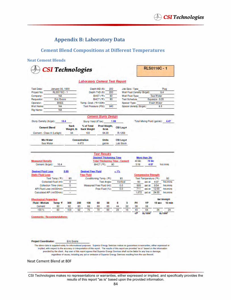
Appendix B: Laboratory Data
Cement Blend Compositions at Different Temperatures
Neat Cement Blends
Neat Cement Blend at 80F
CSI Technologies makes no representations or warranties, either expressed or implied, and specifically provides the results of this report "as is” based upon the provided information.
84
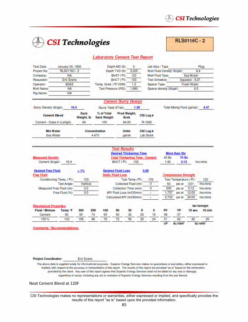
Neat Cement Blend at 120F
CSI Technologies makes no representations or warranties, either expressed or implied, and specifically provides the results of this report "as is” based upon the provided information.
85
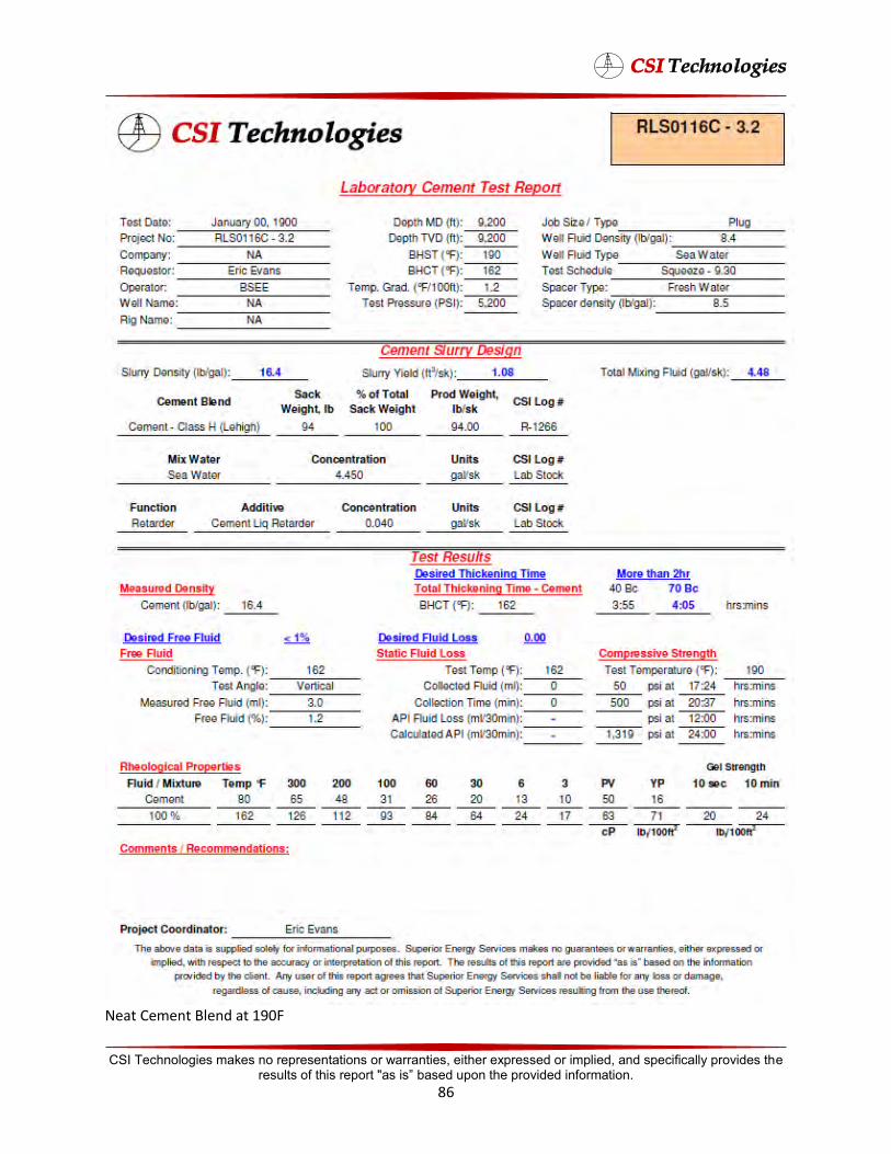
Neat Cement Blend at 190F
CSI Technologies makes no representations or warranties, either expressed or implied, and specifically provides the results of this report "as is” based upon the provided information.
86

Neat Cement Blend at 240F
CSI Technologies makes no representations or warranties, either expressed or implied, and specifically provides the results of this report "as is” based upon the provided information.
87
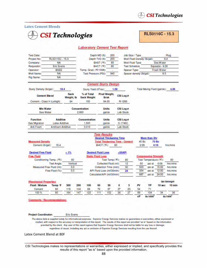
Latex Cement Blends
Latex Cement Blend at 80F
CSI Technologies makes no representations or warranties, either expressed or implied, and specifically provides the results of this report "as is” based upon the provided information.
88
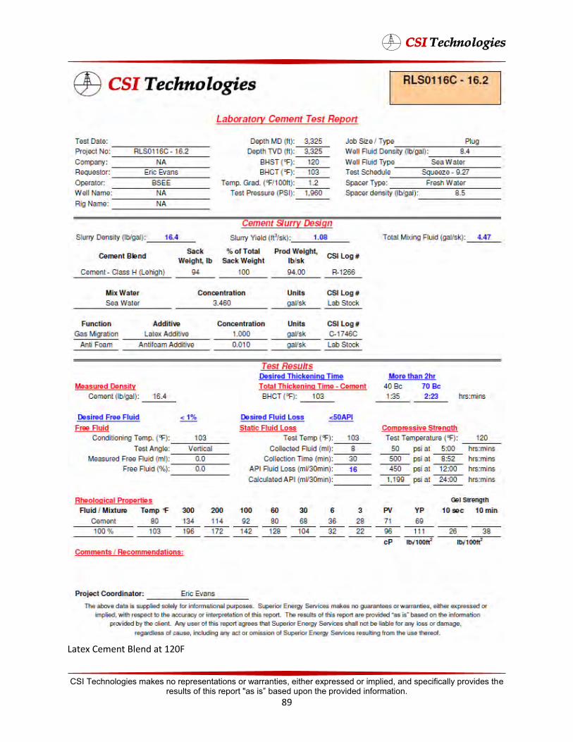
Latex Cement Blend at 120F
CSI Technologies makes no representations or warranties, either expressed or implied, and specifically provides the results of this report "as is” based upon the provided information.
89
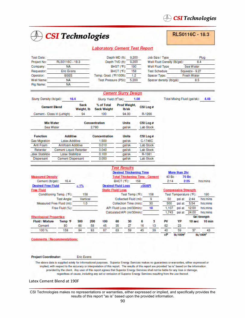
Latex Cement Blend at 190F
CSI Technologies makes no representations or warranties, either expressed or implied, and specifically provides the results of this report "as is” based upon the provided information.
90

Latex Cement Blend at 240F
CSI Technologies makes no representations or warranties, either expressed or implied, and specifically provides the results of this report "as is” based upon the provided information.
91
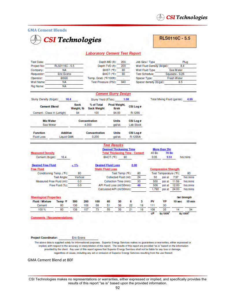
GMA Cement Blend at 80F
CSI Technologies makes no representations or warranties, either expressed or implied, and specifically provides the results of this report "as is” based upon the provided information.
92
GMA Cement Blends
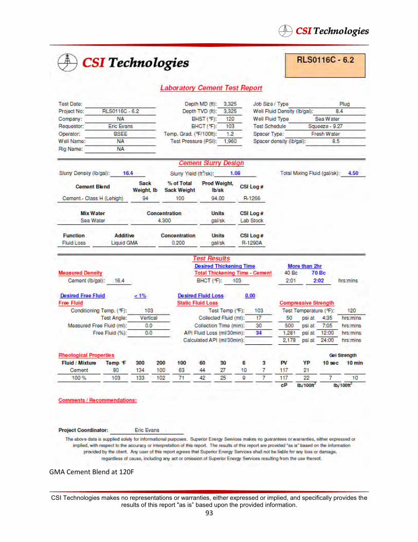
GMA Cement Blend at 120F
CSI Technologies makes no representations or warranties, either expressed or implied, and specifically provides the results of this report "as is” based upon the provided information.
93
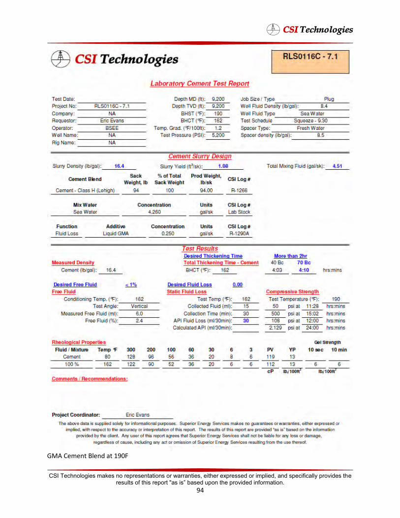
GMA Cement Blend at 190F
CSI Technologies makes no representations or warranties, either expressed or implied, and specifically provides the results of this report "as is” based upon the provided information.
94
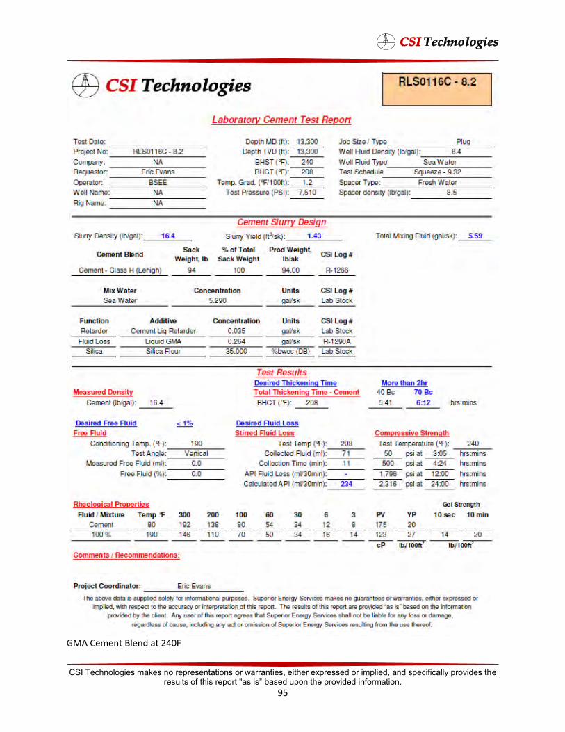
GMA Cement Blend at 240F
CSI Technologies makes no representations or warranties, either expressed or implied, and specifically provides the results of this report "as is” based upon the provided information.
95
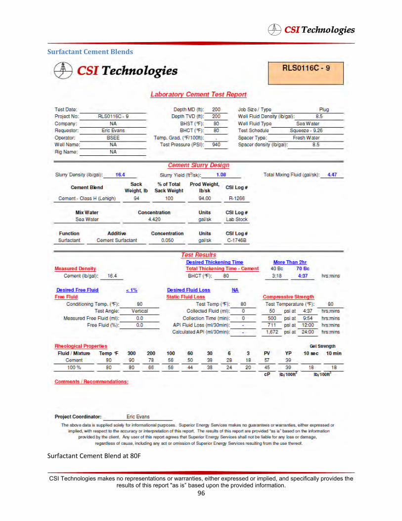
Surfactant Cement Blend at 80F
CSI Technologies makes no representations or warranties, either expressed or implied, and specifically provides the results of this report "as is” based upon the provided information.
Surfactant Cement Blends
96
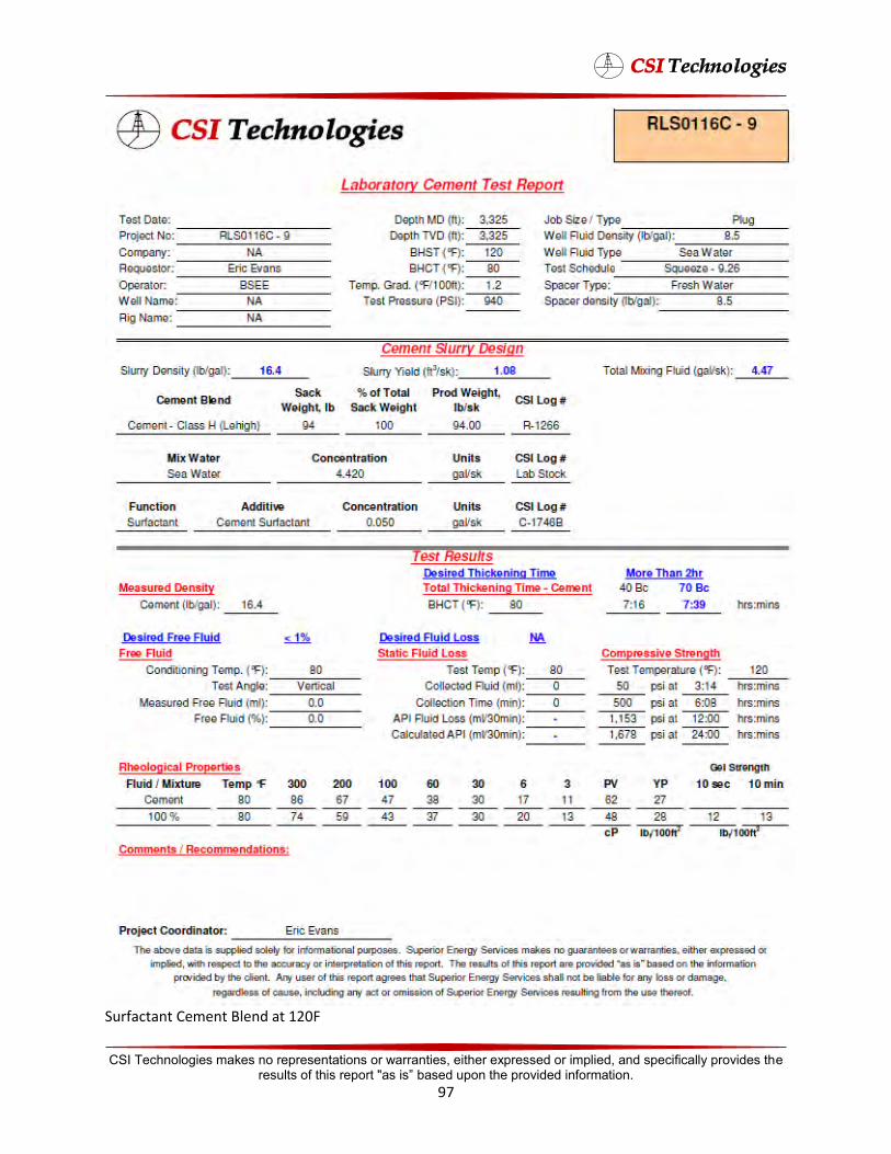
Surfactant Cement Blend at 120F
CSI Technologies makes no representations or warranties, either expressed or implied, and specifically provides the results of this report "as is” based upon the provided information.
97

CSI Technologies makes no representations or warranties, either expressed or implied, and specifically provides the results of this report "as is” based upon the provided information.
98
Surfactant Cement Blend at 190F
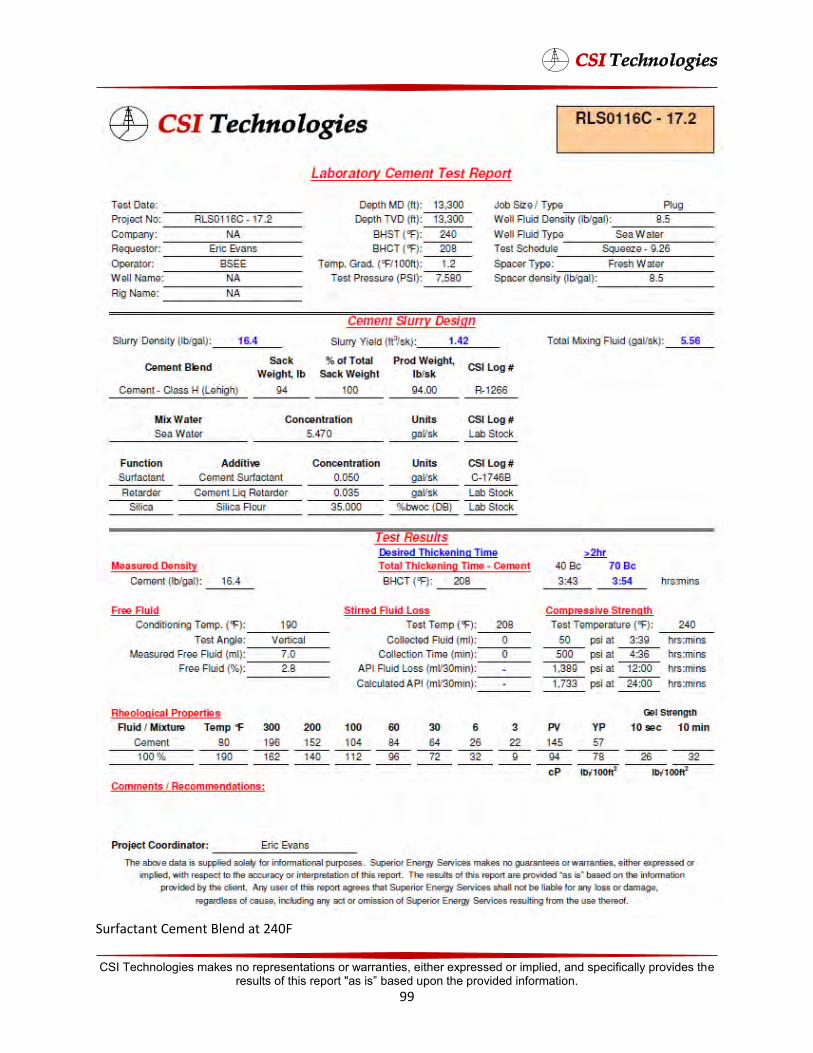
CSI Technologies makes no representations or warranties, either expressed or implied, and specifically provides the results of this report "as is” based upon the provided information.
99
Surfactant Cement Blend at 240F

Expanding Cement Blend at 80F
CSI Technologies makes no representations or warranties, either expressed or implied, and specifically provides the results of this report "as is” based upon the provided information.
100
Expanding Cement Blends
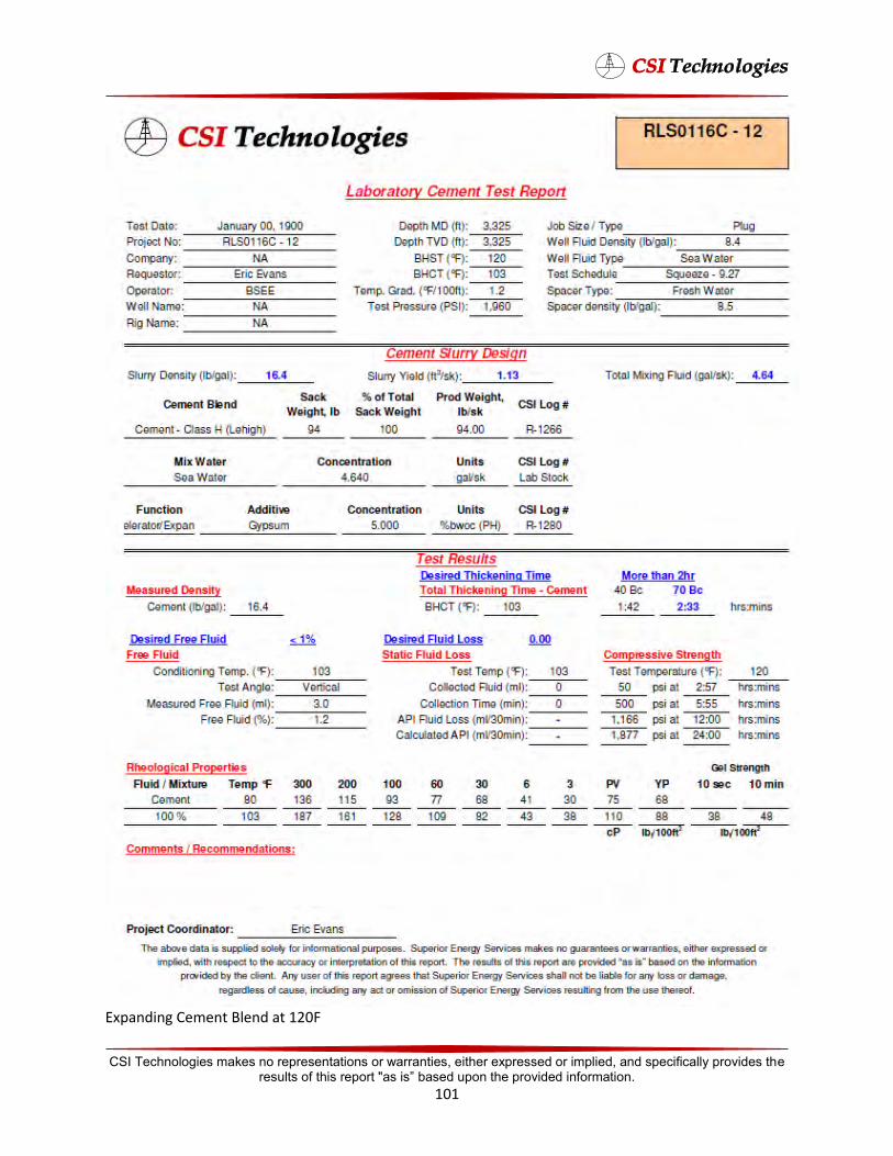
Expanding Cement Blend at 120F
CSI Technologies makes no representations or warranties, either expressed or implied, and specifically provides the results of this report "as is” based upon the provided information.
101
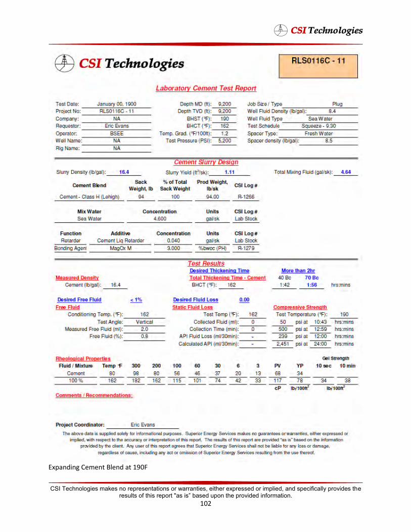
Expanding Cement Blend at 190F
CSI Technologies makes no representations or warranties, either expressed or implied, and specifically provides the results of this report "as is” based upon the provided information.
102

Expanding Cement Blend at 240F
CSI Technologies makes no representations or warranties, either expressed or implied, and specifically provides the results of this report "as is” based upon the provided information.
103
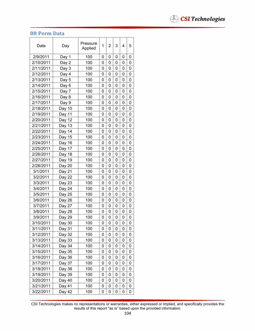
5 10 15 20 25 30 35 40
8ft Perm Data
Date Day Pressure Applied 1 2 3 4 5
2/9/2011 Day 1 100 0 0 0 0 0 2/10/2011 Day 2 100 0 0 0 0 0 2/11/2011 Day 3 100 0 0 0 0 0 2/12/2011 Day 4 100 0 0 0 0 0 2/13/2011 Day 100 0 0 0 0 0 2/14/2011 Day 6 100 0 0 0 0 0 2/15/2011 Day 7 100 0 0 0 0 0 2/16/2011 Day 8 100 0 0 0 0 0 2/17/2011 Day 9 100 0 0 0 0 0 2/18/2011 Day 100 0 0 0 0 0 2/19/2011 Day 11 100 0 0 0 0 0 2/20/2011 Day 12 100 0 0 0 0 0 2/21/2011 Day 13 100 0 0 0 0 0 2/22/2011 Day 14 100 0 0 0 0 0 2/23/2011 Day 100 0 0 0 0 0 2/24/2011 Day 16 100 0 0 0 0 0 2/25/2011 Day 17 100 0 0 0 0 0 2/26/2011 Day 18 100 0 0 0 0 0 2/27/2011 Day 19 100 0 0 0 0 0 2/28/2011 Day 100 0 0 0 0 0 3/1/2011 Day 21 100 0 0 0 0 0 3/2/2011 Day 22 100 0 0 0 0 0 3/3/2011 Day 23 100 0 0 0 0 0 3/4/2011 Day 24 100 0 0 0 0 0 3/5/2011 Day 100 0 0 0 0 0 3/6/2011 Day 26 100 0 0 0 0 0 3/7/2011 Day 27 100 0 0 0 0 0 3/8/2011 Day 28 100 0 0 0 0 0 3/9/2011 Day 29 100 0 0 0 0 0 3/10/2011 Day 100 0 0 0 0 0 3/11/2011 Day 31 100 0 0 0 0 0 3/12/2011 Day 32 100 0 0 0 0 0 3/13/2011 Day 33 100 0 0 0 0 0 3/14/2011 Day 34 100 0 0 0 0 0 3/15/2011 Day 100 0 0 0 0 0 3/16/2011 Day 36 100 0 0 0 0 0 3/17/2011 Day 37 100 0 0 0 0 0 3/18/2011 Day 38 100 0 0 0 0 0 3/19/2011 Day 39 100 0 0 0 0 0 3/20/2011 Day 100 0 0 0 0 0 3/21/2011 Day 41 100 0 0 0 0 0 3/22/2011 Day 42 100 0 0 0 0 0
CSI Technologies makes no representations or warranties, either expressed or implied, and specifically provides the results of this report "as is” based upon the provided information.
104
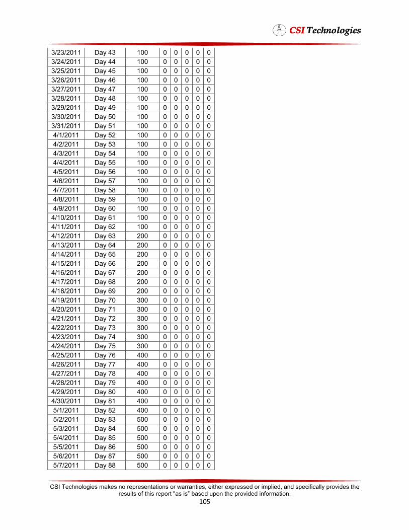
3/23/2011 Day 43 100 0 0 0 0 0 3/24/2011 Day 44 100 0 0 0 0 0 3/25/2011 Day 45 100 0 0 0 0 0 3/26/2011 Day 46 100 0 0 0 0 0 3/27/2011 Day 47 100 0 0 0 0 0 3/28/2011 Day 48 100 0 0 0 0 0 3/29/2011 Day 49 100 0 0 0 0 0 3/30/2011 Day 50 100 0 0 0 0 0 3/31/2011 Day 51 100 0 0 0 0 0 4/1/2011 Day 52 100 0 0 0 0 0 4/2/2011 Day 53 100 0 0 0 0 0 4/3/2011 Day 54 100 0 0 0 0 0 4/4/2011 Day 55 100 0 0 0 0 0 4/5/2011 Day 56 100 0 0 0 0 0 4/6/2011 Day 57 100 0 0 0 0 0 4/7/2011 Day 58 100 0 0 0 0 0 4/8/2011 Day 59 100 0 0 0 0 0 4/9/2011 Day 60 100 0 0 0 0 0 4/10/2011 Day 61 100 0 0 0 0 0 4/11/2011 Day 62 100 0 0 0 0 0 4/12/2011 Day 63 200 0 0 0 0 0 4/13/2011 Day 64 200 0 0 0 0 0 4/14/2011 Day 65 200 0 0 0 0 0 4/15/2011 Day 66 200 0 0 0 0 0 4/16/2011 Day 67 200 0 0 0 0 0 4/17/2011 Day 68 200 0 0 0 0 0 4/18/2011 Day 69 200 0 0 0 0 0 4/19/2011 Day 70 300 0 0 0 0 0 4/20/2011 Day 71 300 0 0 0 0 0 4/21/2011 Day 72 300 0 0 0 0 0 4/22/2011 Day 73 300 0 0 0 0 0 4/23/2011 Day 74 300 0 0 0 0 0 4/24/2011 Day 75 300 0 0 0 0 0 4/25/2011 Day 76 400 0 0 0 0 0 4/26/2011 Day 77 400 0 0 0 0 0 4/27/2011 Day 78 400 0 0 0 0 0 4/28/2011 Day 79 400 0 0 0 0 0 4/29/2011 Day 80 400 0 0 0 0 0 4/30/2011 Day 81 400 0 0 0 0 0 5/1/2011 Day 82 400 0 0 0 0 0 5/2/2011 Day 83 500 0 0 0 0 0 5/3/2011 Day 84 500 0 0 0 0 0 5/4/2011 Day 85 500 0 0 0 0 0 5/5/2011 Day 86 500 0 0 0 0 0 5/6/2011 Day 87 500 0 0 0 0 0 5/7/2011 Day 88 500 0 0 0 0 0
CSI Technologies makes no representations or warranties, either expressed or implied, and specifically provides the results of this report "as is” based upon the provided information.
105
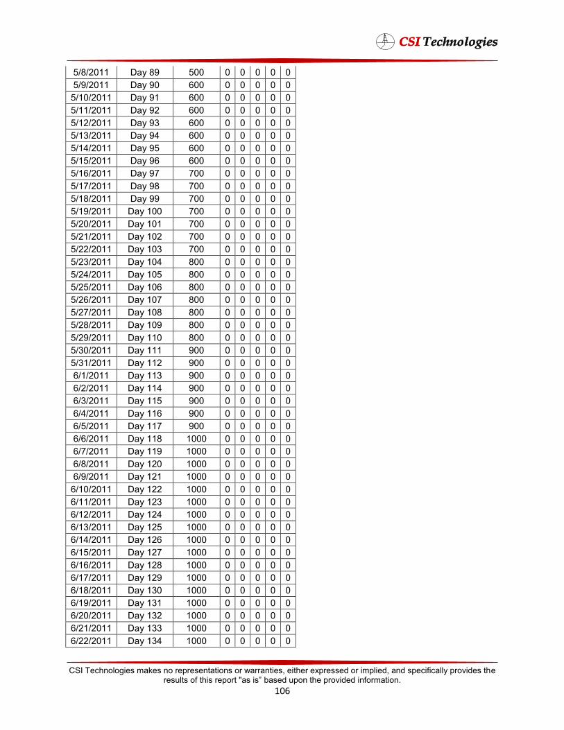
5/8/2011 Day 89 500 0 0 0 0 0 5/9/2011 Day 90 600 0 0 0 0 0 5/10/2011 Day 91 600 0 0 0 0 0 5/11/2011 Day 92 600 0 0 0 0 0 5/12/2011 Day 93 600 0 0 0 0 0 5/13/2011 Day 94 600 0 0 0 0 0 5/14/2011 Day 95 600 0 0 0 0 0 5/15/2011 Day 96 600 0 0 0 0 0 5/16/2011 Day 97 700 0 0 0 0 0 5/17/2011 Day 98 700 0 0 0 0 0 5/18/2011 Day 99 700 0 0 0 0 0 5/19/2011 Day 100 700 0 0 0 0 0 5/20/2011 Day 101 700 0 0 0 0 0 5/21/2011 Day 102 700 0 0 0 0 0 5/22/2011 Day 103 700 0 0 0 0 0 5/23/2011 Day 104 800 0 0 0 0 0 5/24/2011 Day 105 800 0 0 0 0 0 5/25/2011 Day 106 800 0 0 0 0 0 5/26/2011 Day 107 800 0 0 0 0 0 5/27/2011 Day 108 800 0 0 0 0 0 5/28/2011 Day 109 800 0 0 0 0 0 5/29/2011 Day 110 800 0 0 0 0 0 5/30/2011 Day 111 900 0 0 0 0 0 5/31/2011 Day 112 900 0 0 0 0 0 6/1/2011 Day 113 900 0 0 0 0 0 6/2/2011 Day 114 900 0 0 0 0 0 6/3/2011 Day 115 900 0 0 0 0 0 6/4/2011 Day 116 900 0 0 0 0 0 6/5/2011 Day 117 900 0 0 0 0 0 6/6/2011 Day 118 1000 0 0 0 0 0 6/7/2011 Day 119 1000 0 0 0 0 0 6/8/2011 Day 120 1000 0 0 0 0 0 6/9/2011 Day 121 1000 0 0 0 0 0 6/10/2011 Day 122 1000 0 0 0 0 0 6/11/2011 Day 123 1000 0 0 0 0 0 6/12/2011 Day 124 1000 0 0 0 0 0 6/13/2011 Day 125 1000 0 0 0 0 0 6/14/2011 Day 126 1000 0 0 0 0 0 6/15/2011 Day 127 1000 0 0 0 0 0 6/16/2011 Day 128 1000 0 0 0 0 0 6/17/2011 Day 129 1000 0 0 0 0 0 6/18/2011 Day 130 1000 0 0 0 0 0 6/19/2011 Day 131 1000 0 0 0 0 0 6/20/2011 Day 132 1000 0 0 0 0 0 6/21/2011 Day 133 1000 0 0 0 0 0 6/22/2011 Day 134 1000 0 0 0 0 0
CSI Technologies makes no representations or warranties, either expressed or implied, and specifically provides the results of this report "as is” based upon the provided information.
106

6/23/2011 Day 135 1000 0 0 0 0 0 6/24/2011 Day 136 1000 0 0 0 0 0 6/25/2011 Day 137 1000 0 0 0 0 0 6/26/2011 Day 138 1000 0 0 0 0 0 6/27/2011 Day 139 1000 0 0 0 0 0 6/28/2011 Day 140 1000 0 0 0 0 0 6/29/2011 Day 141 1000 0 0 0 0 0 6/30/2011 Day 142 1000 0 0 0 0 0 7/1/2011 Day 143 1000 0 0 0 0 0 7/2/2011 Day 144 1000 0 0 0 0 0 7/3/2011 Day 145 1000 0 0 0 0 0 7/4/2011 Day 146 1000 0 0 0 0 0 7/5/2011 Day 147 1000 0 0 0 0 0 7/6/2011 Day 148 1000 0 0 0 0 0 7/7/2011 Day 149 1000 0 0 0 0 0 7/8/2011 Day 150 1000 0 0 0 0 0 7/9/2011 Day 151 1000 0 0 0 0 0 7/10/2011 Day 152 1000 0 0 0 0 0 7/11/2011 Day 153 1000 0 0 0 0 0 7/12/2011 Day 154 1000 0 0 0 0 0 7/13/2011 Day 155 1000 0 0 0 0 0 7/14/2011 Day 156 1000 0 0 0 0 0 7/15/2011 Day 157 1000 0 0 0 0 0 7/16/2011 Day 158 1000 0 0 0 0 0 7/17/2011 Day 159 1000 0 0 0 0 0 7/18/2011 Day 160 1000 0 0 0 0 0 7/19/2011 Day 161 1000 0 0 0 0 0 7/20/2011 Day 162 1000 0 0 0 0 0 7/21/2011 Day 163 1000 0 0 0 0 0 7/22/2011 Day 164 1000 0 0 0 0 0 7/23/2011 Day 165 1000 0 0 0 0 0 7/24/2011 Day 166 1000 0 0 0 0 0 7/25/2011 Day 167 1000 0 0 0 0 0 7/26/2011 Day 168 1000 0 0 0 0 0 7/27/2011 Day 169 1000 0 0 0 0 0 7/28/2011 Day 170 1000 0 0 0 0 0 7/29/2011 Day 171 1000 0 0 0 0 0 7/30/2011 Day 172 1000 0 0 0 0 0 7/31/2011 Day 173 1000 0 0 0 0 0 8/1/2011 Day 174 1000 0 0 0 0 0 8/2/2011 Day 175 1000 0 0 0 0 0 8/3/2011 Day 176 1000 0 0 0 0 0 8/4/2011 Day 177 1000 0 0 0 0 0 8/5/2011 Day 178 1000 0 0 0 0 0 8/6/2011 Day 179 1000 0 0 0 0 0 8/7/2011 Day 180 1000 0 0 0 0 0
CSI Technologies makes no representations or warranties, either expressed or implied, and specifically provides the results of this report "as is” based upon the provided information.
107
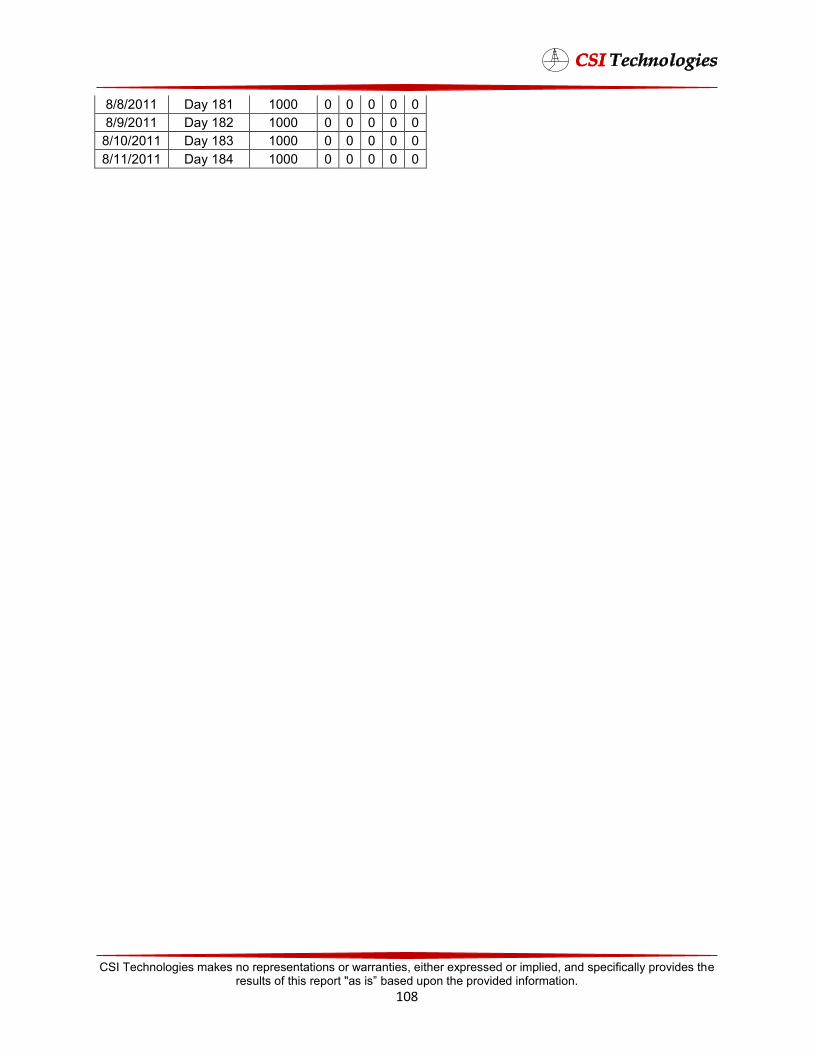
8/8/2011 Day 181 1000 0 0 0 0 0 8/9/2011 Day 182 1000 0 0 0 0 0 8/10/2011 Day 183 1000 0 0 0 0 0 8/11/2011 Day 184 1000 0 0 0 0 0
CSI Technologies makes no representations or warranties, either expressed or implied, and specifically provides the results of this report "as is” based upon the provided information.
108