Embed Size (px)
Citation preview

Annual Report 2005
2006
SPACE INSTITUTE Tullahoma, Tennessee
Center for
Laser
Applications

i
Exe
cutiv
e S
um
maryCenter for
Laser
Applications
This has been an exciting year at the Center for Laser Applications. In this report you will find that our continued research themes are strong and successful, and our new initiatives are gaining traction in the research community. We had over two million dollars in research funds expended this past year and expect the next year to be even better. Thirty-six refereed journal articles were published by CLA faculty. We announced a new Center for Advanced Photonic Processing which is a formal alignment of CLA with laser materials processing at UT Knoxville and the infrared photonic processing efforts at Oak Ridge National Laboratory. We are working towards a serious program in nano manufacturing with several activities. We purchased a new high power femtosecond laser source for materials processing which will be the centerpiece for our nanofabrication efforts. This equipment will enable work in materials modification of photonic materials and diamond microelectronics. The laser, along with an ultra high vacuum system, vacuum compatible nano-positioning stage and reflection time of flight mass spectrometer will be housed in the CLA clean room which is scheduled for completion by the end of the calendar year. One use of nanoscale fabrication is to support Professor Davis’ single molecule spectroscopy research. A proposal to the Center for Nanomaterials Science at Oak Ridge National Laboratory to study nanochannel fabrication for single molecule detection was approved. CLA now has access to this national resource. This nanofabrication effort will keep our ultra fast spectroscopy work on biomolecules at the cutting edge and solidify Prof. Davis’ national prominence in single molecule spectroscopy.
Professor Moeller continues his work in non-equilibrium fluid (plasma) physics with several grants and a particularly large effort with General Atomics for hypersonic vehicle electric power systems. Professors Lewis and Chen have been successful in securing continued funding for their eye screening program and have launched an effort in laser induced breakdown spectroscopy for two-phase, time-dependant rocket combustion. The materials processing group (Hofmeister) secured funding from Advanced Powder Solutions for net-shape consolidation of nano-encapsolated powders. This effort includes
Executive Summary
ii
Exe
cutiv
e S
um
marycollaboration with Oak Ridge National Laboratory under the banner of the Center
for Advanced Photonic Processing. Professor Dahotre was elected a Fellow of ASM International, Received the UT Chancellor’s Research and Creativity Achievement Award, the College of Engineering Research Fellow Award, and continues to work on surface modification using lasers. Industrial interest in our capabilities remains strong. We performed educational and consulting services for Fisher USA, and are negotiating with Baker Oil Tools and Lennox to implement LISI technology in their businesses portfolios.
We submitted several proposals this year to NIH, NSF, DEPSCoR and DARPA programs. The NSF NIRT submission last year was not successful and will be resubmitted this fall with the reviewers concerns addressed. The general theme of these proposals is to combine nanofabrication with single molecule spectroscopy and build on the strengths of Prof. Davis’ and Hofmeister’s nationally recognized expertise.
The key to success in a research institution is the talent and innovation of its scientists and engineers. In the past year we have added four postdoctoral fellows to our personnel pool: Lino Costa from Instituto Superior Tecnico, Lisbon, Portugal; Xiaoxuan Li from the University of Connecticut; Yelena White from Vanderbilt University, and Zbigniew Sikorski, from Warsaw University of Technology, Warsaw, Poland, by way of CFD Research in Huntsville, Alabama. These individuals are making significant contributions to our research endeavors. The UTSI revitalization plan is driving the addition of faculty to the materials science area at CLA. One tenure track and two research faculty positions in materials science will be available next year.
Our ability to hire new postdoctoral fellows and secure state-of-the-art equipment comes from a realignment of the resources of CLA. We have shifted funds from tenured and research faculty salaries to postdoctoral fellows and equipment. This also enabled hiring seven summer interns (high school and undergraduate) to participate in research in CLA’s laboratory.
This year we made major advances in our community outreach. CLA is dedicated to impacting our community in a positive way and meaningful interactions with area students is a great contribution. To supplement our “tour” programs, we coordinated “mini-courses” with UTSI faculty for high school students, conducted three science camps this summer, and employed seven interns.
We did have our share of sadness with the passing of Mr. Fred Schwartz on December 6, 2005. Fred was a technician with CLA since its inception. His enthusiasm and competence will be sorely missed. Fred was a major driver in the laser materials processing area and developed many applications for CLA processes with industrial partners in Tennessee. His work ethic and spirit were an inspiration to all.
____________________________________William HofmeisterResearch Professor of Materials Science and EngineeringDirector, Center for Laser Applications

iii
Table
of C
onte
nt
Table of ContentExecutive Summary ................................................................................................... I
Table of Contents ..................................................................................................... III
Focus AreaLaser Materials Processing ..................................................................................... 1
Introduction LISI Processing Laser Induced Surface Improvement (LISI) Applications 1. Laser Alloyed Identification Tags 2. LISI Processing of WC Precursors
3. Nanodiamond as a Carbon Source in Laser Materials Processing 4. Finite Element Modeling of the LISI Process New Equipment and Software Development Technical Support and Consultation Service for Fischer USA Laser Patterning of Diamond Microelectronics Laser Induced Hierarchical Calcium Phosphate Structures Laser Surface Processing of Ti6A14V in Gaseous Nitrogen for Biomedical Applications Non-equilibrium Modeling of Microstructure Evolution in Rapid Solidification of Laser
Dressed Alumina Grinding Wheels Laser Cladding of Fe-Cr-Mo-Y-B-C Bulk Metallic Glass on Steel Substrate Laser Surface Modifications of Alumina Grinding Wheels for Micro-scale Material
Removal
Focus AreaUltrasensitive Fluorescence Spectroscopy .............................................................. 40
Introduction Ultrasensitive Fluorescence Spectroscopy New Methodology for Fluorescence Correlation Spectroscopy Single-Molecule Detection with Axial Flow Single-Molecule Trapping Maximum Likelihood Multi-Channel Photon-Counting Microscopy Computer Modeling and Simulations Polarization-Engineered Microscopy High-Efficiency Single-Photon Detection with Picosecond Timing Resolution Femtosecond Laser Developments Other Activities in the Ultrasensitive Fluorescence Spectroscopy Focus Area Laser-Induced Breakdown Spectroscopy Laser-Induced Breakdown Spectroscopy of Bipropellant Rocket Engine

iv
Table
of C
onte
nt
Focus AreaNanofabrication ..................................................................................................... 58
Introduction Nanofluidics for Single Molecule Sensing and Manipulation Introduction Planar Fabrication 1. Microchannels and Nanochannels Fabrication 2. Thermal Bonding Trials 3. Microfluidics Device Fabrication and Testing Laser Fabrication
Focus AreaNonequilibrium Fluid Physics................................................................................. 65
Introduction Nuclear Fission electric Power and Propulsion, AEDC Task 03-01 Vertical EP Thrust Stand for 12V Vacuum Chamber, AEDC Task 03-01 Vertical EP Thrust Stand for 12V Vacuum Chamber, AEDC Task 06-03 MACH2 Simulations of a Laser Ablation Thruster Hypersonic Vehicle Electric Power System (HVEPS)
Focus AreaBiomedical Applications ......................................................................................... 72
Introduction Optical Physics in CLA Biomedical Information Technology (BIT) Network Ophthalmic Instrumentation Ophthalmic Simulation and Keratoconus Research
Enrichment Programs ................................................................................................ 78
Coffee County Middle School Demonstration Science Expose “Engineer for a Day Program” ASM Materials Camp Mad Science Camp UTSI/CLA Shodor Scholars Program Science Fairs Outreach to Business................................................................................................. 82
Fischer USA ATI Metalworking Products

v
Table
of C
onte
nt
Budget Forms
Center of Excellence/Center of Emphasis Actual, Proposed,
and Requested Budget .............................................................................................. 102
Schedule 1A - Center of Excellence Actual 2005-2006 Personnel ................................. 103
Schedule 1B - Center of Excellence Proposed 2006-2007 Personnel ............................. 104
Schedule 1C - Center of Excellence Requested 2007-2008 Personnel ........................... 105
Schedule 2A - Center of Excellence Actual Equipment, 2005-2006 .............................. 106
Schedule 2B - Center of Excellence Proposed Equipment, 2006-2007 .......................... 107
Schedule 2C - Center of Excellence Requested Equipment, 2007-2008 ......................... 108
Schedule 3A - Center of Excellence Base Support and Non-Equipment
Matching Actual 2005-06 ......................................................................................... 109
Schedule 3B - Center of Excellence Base Support and Non-Equipment
Matching Proposed 2006-07 ..................................................................................... 110
Schedule 3C - Center of Excellence Base Support and Non-Equipment
Matching Requested 2007-08 .................................................................................... 111
Visitors to the Laboratory FY 05-06 ............................................................................ 83
Awarded Grants and Contracts .................................................................................. 87
Students............. ........................................................................................................ 90
Interns for Summer 2006 .......................................................................................... 92
Publications and Presentations ................................................................................... 94
Future Directions for the Center for Laser Applications ................................................. 100

1
Focu
s A
rea
Focus
Area
Laser Materials
Processing
Introduction
Laser materials processing has been a cornerstone of CLA for a number of years. This year we formed the Center for Advanced Photonic Processing with UT Knoxville and Oak Ridge National Laboratory to facilitate joint research in materials processing. Our collaborations with industry and other academic institutions continues to be strong. Efforts in this area will be critical in developing materials science research at UT Space Institute.
The section begins with the Laser Induced Surface Improvement (LISI) Process which was developed at UTSI a number of years ago, and has been funded by the Air Force. Following this are reports on more recent advances in surface modification, electronic and biological material processing.

2Laser Materials Processing
Focu
s A
reaLISI Process
LISI stands for Laser Induced Surface Improvement and is a process where a laser source is used to create an alloy layer on the surface of a material to improve some property of the surface, such as wear or corrosion resistance. LISI was developed at CLA and the University of Tennessee Research Foundation holds a number of patents for LISI processes. Lasers, other optical sources, radio frequency sources and furnaces are commonly used to change surface properties with thermal treatment. The properties of materials are controlled by their structure, and in complex alloys, the thermal treatments can allow different structures (or phases) to form based on the thermal history. Steels are heated in furnaces with nitrogen and carbon containing atmospheres, which alter the chemistry of the surface layer and change the properties of the surface as well.
Lasers are also used in a process called cladding, where a layer of molten material is deposited on a surface. The laser is focused on the substrate and a molten area is formed. Additional material is added to the original surface by a wire feeder or a powder spray. In cladding, layers as thick as one inch can be applied to substrates. It is even possible, in some circumstances, to layer a completely different type of material on the surface, creating an entirely new composition on the old substrate. The disadvantage of cladding is the presence of residual stress in the deposits. Since the thermal energy is extracted through the substrate, the thermal gradients normal to the layer are very large and the thermal expansion is not even throughout the processing range. This can lead to residual stresses in the layers of the deposit. Also, cladding is similar to welding, in that relatively large amounts of molten material exist during processing. This thermal energy creates a so called “heat affected zone” (HAZ), where the structure of the substrate is changed in a manner that is not desirable. The heat affected zone in normally the weakest point in a weld and a common delimitation failure point in laser clad material.
The LISI process is somewhere in between surface treatment and laser cladding. In LISI a metal or metal/ceramic mixture is pre-placed on the surface and alloyed into the surface using a laser. The powder is mixed with a binder and sprayed on the surface forming a layer similar to a layer of paint. This layer is dried and then treated with the laser. In this process we are changing the chemistry of the surface layer, but only applying enough thermal energy to melt a thin layer at a high translational velocity. This means that we alloy the material into the surface and then instantly quench the layer. In cladding, the cooling rates can be from 10-100 degrees C per second. With LISI the cooling rates are 103-104 degrees C per second. These high quench rates significantly reduce the heat affected zone to less than a few tens of microns, minimizing the detrimental effects experienced in cladding and welding operations.
Laser Induced Surface Improvement (LISI) Applications
The LISI process was developed at CLA and is covered by a variety of patents. This year we completed work on contract AF F40600-00-D-0001-0015 with the United States Air Force whose purpose was to develop LISI applications for the Department of Defense.
3Laser Materials Processing
Focu
s A
reaThis year we performed work in four particular areas:
• Laser marking using LISI
• Ultrahigh temperature, wear resistant refractory coatings
• Surfacing of diesel engine cylinders
• Modeling of LISI processing
1. Laser Alloyed Identification Tags
A LISI-type laser marking technique was developed at the Center for Laser Applications (CLA) to address the need of the Department of Defense for materiel identification tags that withstand harsh environmental conditions. With LISI-type laser marking, identification tags with enhanced corrosion and wear resistance are produced by laser melting a precursor – a 20 to 150 m thick, pre-placed deposit of bonded powder materials containing corrosion and wear resistant substances – into a thin surface layer of the item being tagged, thus modifying the chemical composition, microstructure and properties of the material. Chrome-rich precursors and precursors containing hard phases, such as borides and carbides, have been investigated specifically for corrosion and erosion resistance purposes. For robust and durable tags, these precursor materials are mixed with molten base material and form a fully dense, low-dilution fusion bonded LISI layer during laser processing. And for certain applications such tags are of interest only if the fatigue resistance of the tagged items is not significantly impaired during laser processing. Lastly, these tags have to present well defined and contrasted features that ensure good readability.
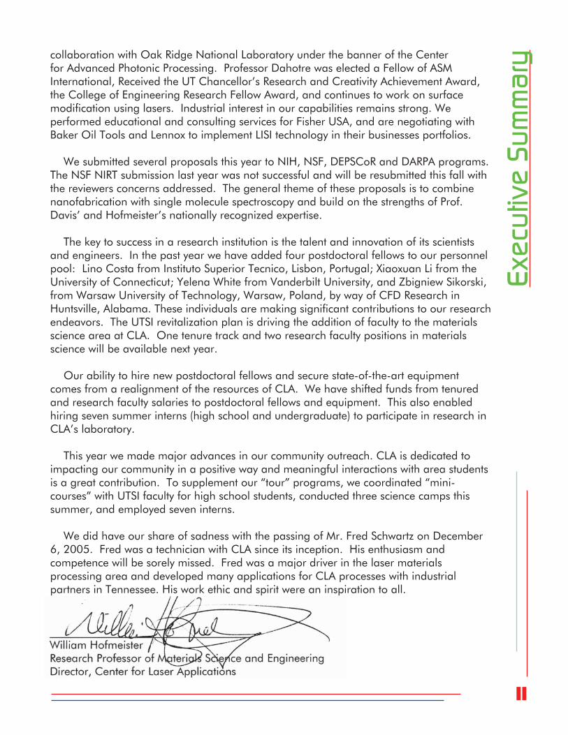
Metallurgically sound LISI-type identification tags are produced rapidly and precisely using galvanically driven laser beam scanning heads capable of confining the laser processing operation locally to sub-millimeter scale regions, thus allowing unique serial numbers, linear barcodes and 2D data matrix marks to be formed with very small and detailed geometric features. At CLA, the LISI-type laser marking technique was developed using two distinct laser marking systems that offer a wide range of laser processing conditions: a 7 W Q-switched (pulsed) Nd:YAG (1064 nm) VectorMark system (Figure 1) and a 1 kW CW IPG fiber laser (1070 nm) coupled to a HurryScan30 galvanically driven scan head (Figure 2).
Figure 1 – 7 W Q-switched Nd:YAG (1064 nm)
VectorMark system

4Laser Materials Processing
Focu
s A
reaFigure 2 – 1 kW CW IPG fiber laser
(1070 nm) coupled to a HurryScan30
galvo driven scan head
To identify laser processing conditions leading to satisfactory results, LISI-type data matrix marks were characterized in detail for a wide range of distinct laser processing parameter values. Optical and scanning electron microscopy analysis of cross-sectioned marks was used to exclude all trial samples
exhibiting pores, cracks or poor adhesion of the LISI layer to the base material from further analysis, while chemical analysis was used to verify the alloy content within the LISI layer. Metallurgically sound samples were submitted to hardness measurements on the LECO system (Figure 3), to sand erosion tests on a Plint TE68 Gas Jet Erosion Rig1 (Figure 4) and to corrosion tests in a Q-Fog Cyclic Corrosion Tester2 (Figure 5). The readability of as-processed, eroded or corroded marks was verified using the DMx verifier system shown in Figure 6. For eroded or corroded marks classified as unreadable, a treatment comprising sand-blasting and chemical etching was used to reveal the underlying LISI layer and
enhance the contrast of the LISI processed areas. Cleaning was accomplished in this manner for previously unreadable samples, and those samples were tested again for readability.
Figure 3 – LECO hardness
tester
To identify situations and materials that may truly benefit from LISI-type laser marking, trial marks were
performed on several commonly used structural materials – including aluminum alloys 6061 and 7075, steels 4340 and 1018, Ti6Al4V and nickel-based superalloy Haynes 230 – and compared to standard bare surface laser markings performed using the same laser processing conditions.
1 complies with the ASTM G76 standard2 complies with the ASTMB117 standard3 complies with the AIM uniform symbology specification for data matrix symbology

5Laser Materials Processing
Focu
s A
rea
Figure 4 – Plint TE68 Gas Jet Erosion Rig
Figure 5 – Q-Fog Cyclic Corrosion Tester
Figure 6 – RVSI DMx Verifier
6Laser Materials Processing
Focu
s A
reaThe current R&D effort on LISI-type laser marking has led to the following results for the
VectorMary System (A) and the 1kW IPG laser scanning system (B):
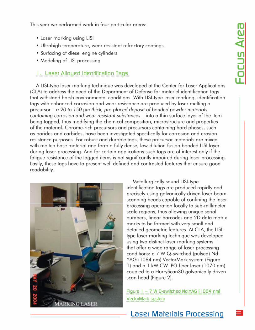
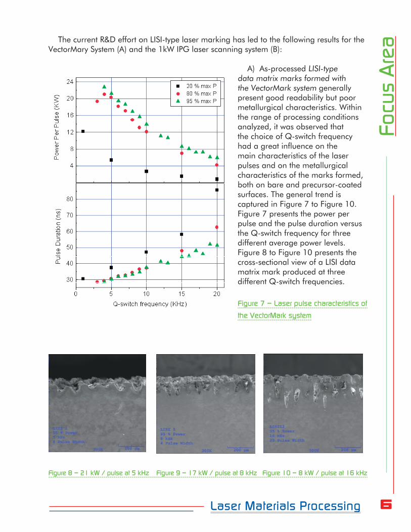
A) As-processed LISI-type data matrix marks formed with the VectorMark system generally present good readability but poor metallurgical characteristics. Within the range of processing conditions analyzed, it was observed that the choice of Q-switch frequency had a great influence on the main characteristics of the laser pulses and on the metallurgical characteristics of the marks formed, both on bare and precursor-coated surfaces. The general trend is captured in Figure 7 to Figure 10. Figure 7 presents the power per pulse and the pulse duration versus the Q-switch frequency for three different average power levels. Figure 8 to Figure 10 presents the cross-sectional view of a LISI data matrix mark produced at three different Q-switch frequencies.
Figure 7 – Laser pulse characteristics of
the VectorMark system
Figure 8 – 21 kW / pulse at 5 kHz Figure 9 – 17 kW / pulse at 8 kHz Figure 10 – 8 kW / pulse at 16 kHz

7Laser Materials Processing
Focu
s A
reaThese LISI laser marking experiments were performed with three different precursor
materials – CrB2, Mo2B5 and W2B – applied on 4340 steel. In general, it was found that the nanosecond, multi-kilowatt laser pulses produced by the VectorMark system are capable of mixing and bonding these precursor materials with the base material within ~100 m wide tracks that overlap to produce 50-100 m thick LISI layers. Marks produced at the lower end of Q-switching frequency values usually present a very thin laser modified layer (50 m) characterized by low precursor material content. Both LISI layer thickness and precursor material content tend to increase with increasing Q-switch frequency. While low Q-switching frequencies tend to produce rough, pore-free layers (Figure 8), an increase in Q-switching frequency leads progressively to the formation of pores within the LISI layer (Figure 9) that eventually extend into the base material by as much as 200 m at the upper end of the Q-switching frequency range (Figure 10). Attempts to regulate the intensity of the laser pulses (either by reducing the power per pulse or by defocusing the laser beam) were not particularly effective in eliminating these pores, expected to have a detrimental effect on the fatigue resistance of the marked part. SEM analysis also revealed that the surface finish of the base material plays a significant role in the adhesion of the precursor materials to the surface of the base material (Figure 11). In particular, surface roughness tends to be detrimental to the bonding of the precursor material to the base material.
Figure 11 – View of a ground-off LISI
processed surface. Note the presence
of numerous pores and how the surface
finish of the base material affects the
bonding of the precursor material.
Despite the poor metallurgical properties, the erosion resistance of these marks was tested: an array of VectorMark LISI-type data matrix marks based on CrB2, Mo2B5 and W2B precursors where applied on to the surface of a superalloy Rene 41 jet engine exhaust J85 nozzle leaf provided by AEDC (Figure 12), according to the conditions in Table 1. These conditions were selected based on results from preliminary marking trials performed on Haynes 230.

8Laser Materials Processing
Focu
s A
rea
Figure 12 – As-processed LISI-type data matrix
marks on the J85 nozzle leaf before jet engine
test run
Table 1 – Laser processing conditions, at 95% maximum average power
The marked leaf was installed into the jet engine nozzle and submitted to several jet engine test runs, according to the conditions in Table 2 to Table 5 and summarized in Table 6.
Table 2 – For run 0010, 02/16/2006
Table 3 – For run 0011, 02/17/2006

9Laser Materials Processing
Focu
s A
reaTable 4 – For run 0012, 05/25/2006
Table 5 – For run 0013, 05/31/2006
Table 6 – Overall testing time and condition
Figure 13 depicts the nozzle leaf after run #0010c
Figure 13 – The LISI-marked J85 nozzle leaf after one
of several jet engine test runs
It should be noted that the exit plane temperatures vary between 850°F (450°C) at idle and 1250 °F (675°C) at 100%, while the after-burner (A/B) spikes temperatures up to 3200°F
(1760°C). Overall, the nozzle lead was exposed to 507 minutes of jet engine test runs and 8 minutes of after-burner. Despite the extreme conditions, the LISI marks survived the test (Figure 14).
Figure 14 – The LISI-marked J85 nozzle leaf after being
submitted to a series of jet engine test runs

10Laser Materials Processing
Focu
s A
reaOnly the marks based on the CrB2 precursor were readable by the RVSI DMx verifier
system, however. All marks based on Mo2B5 and W2B precursors failed this specific readability test with no chemical etching or cleaning to enhance the contrast of the marks. The obtained results are summarized in Table 7.
Table 7 – Readability of LISI-type data matrix marks on the J85 nozzle leaf
after being submitted to a series of jet engine test runs
Of the three precursors tested, CrB2 produced the best results. LISI-type CrB2-containing marks are superior to standard, bare surface laser markings when it comes to high temperature erosion resistance.

11Laser Materials Processing
Focu
s A
reaMetallurgically sound LISI-type data matrix marks formed with the 1 kW CW IPG fiber
laser HurryScan30 system were obtained over a relatively wide range of laser processing conditions, as seen in the cross-sectional SEM micrographs depicted in Figure 15 to Figure 20.
Figure 15 – CrB2 at 175 W Figure 16 – Mo
2B5 at 200W Figure 17 – W
2B at 150W
Figure 18 - CrB2 at 500 W, 500 mm/s Figure 19 - Mo
2B
5 at 500 W, 500 mm/s Figure 20 - W
2B at 500 W, 500 mm/s
These LISI-type laser markings were performed for different precursor materials – CrB2, Mo2B5 and W2B – on 4340 steel. With the laser beam focused on the sample’s surface and being scanned at 50 mm/s, it was observed that the different precursors require different power settings to achieve adequate mixing and bonding with the base material: W2B requires at least 150 W (Figure 17), while CrB2 requires 175 W (Figure 15) and Mo2B5 requires 200 W (Figure 16). Although some samples produced at higher power settings do present a LISI layer with cracks (Figure 21), in general the LISI layers were found to be fully dense, crack-free and fusion-bonded with the base material. Combined with the relatively small heat affected zone (HAZ), one can expect these marks to have a less detrimental effect on the fatigue resistance of the marked items as compared to VectorMark marks characterized by rough LISI layers with deep reaching pores.

12Laser Materials Processing
Focu
s A
reaFigure 21 – CrB
2-containing layer exhibiting
some cracks
The corrosion and erosion resistance of the processed regions is expected to depend on the concentration of precursor materials within the LISI layer. The variation of LISI layer thickness and dilution of the precursor materials with laser processing conditions is summarized in the following graphs.
Figure 22 – Layer thickness and alloy
content versus laser beam power at
the specified scan speed (S) and work
distance (Focus)
Figure 23 – Layer thickness and alloy
content versus laser beam power at
the specified scan speed (S) and work
distance (Focus)
120 140 160 180 20020406080
100120140160
CrB2 thickness Mo2B5 thickness W2B thickness
Laye
r thi
ckne
ss (u
m)
Laser Power (W)120 140 160 180 200 0
102030405060708090100
S=50 mm/sFocus=355 mm
Dilu
tion
of c
hem
ical
ele
men
t (%
)
Cr dilution Mo dilution W dilution
120 140 160 180 20040
80
120
160
200
240
CrB2 thickness Mo2B5 thickness W2B thickness
Laye
r thi
ckne
ss (u
m)
Laser Power (W)120 140 160 180 200 0
20
40
60
80
100
S=50 mm/sFocus=348 mm
Dilu
tion
of c
hem
ical
ele
men
t (%
)
Cr dilution Mo dilution W dilution

13Laser Materials Processing
Focu
s A
rea
Figure 24 – Layer thickness and alloy
content versus scan speed at the
specified laser beam power (P) and
work distance (Focus)
These graphs show that LISI layer thickness generally increases by increasing the laser beam power or reducing the scan speed. Changes in LISI layer thickness do not necessary correspond to significant changes in the dilution of the alloying elements. The thickness of the LISI layer and the dilution of the chemical species of the precursor material appear to depend strongly on the particular precursor material. Despite the good structural characteristics of these LISI layers, the precursor substances added to the base material’s surface appear in very dilute quantities within the LISI layer, which may undermine the efforts to significantly enhance the erosion or corrosion properties of the laser processed areas.
Erosion and corrosion tests were performed on selected samples. Results obtained for trial samples prepared on 4340 steel using Cr-CrB2 precursors using two distinct laser processing conditions (Fast: 300 W and 300 mm/s; Slow: 200 W and 100 mm/s) are presented in Tables 8, 9, and 10.
As a result of this study we will recommend to the Air Force that Q-switched, marking lasers should not be used in applications where corrosion or fatigue may present a problem in part performance. The continuous wave, high power scanning laser can make marks that are effective, long lasting and readable even after exposure to extreme conditions. Our results show that the higher power, continuous scan can produce these marks with a very small heat affected zone and no cracking in the substrate.
280 320 360 400 440 480 520406080
100120140160180200
CrB2 thickness Mo2B5 thickness W2B thickness
Laye
r thi
ckne
ss (u
m)
Scan Speed (mm/s)280 320 360 400 440 480 5200
102030405060708090100
P=500 WFocus=355 mm
Dilu
tion
of c
hem
ical
ele
men
t (%
)
Cr dilution Mo dilution W dilution

14Laser Materials Processing
Focu
s A
rea
Table 8 – Cross-sectional micrographs and hardness maps of
as-processed Cr-CrB2 containing LISI-type marks

15Laser Materials Processing
Focu
s A
rea
Table 9 – Readability of sand-eroded Cr-CrB2 containing LISI-type marks

16Laser Materials Processing
Focu
s A
reaTable 10 – Readability of corroded Cr-CrB
2 containing LISI-type marks
2. LISI Processing of WC Precursors
LISI processing of 4130 and 4340 steels and Stellite 6 substrates coated with a ATI Alldyne WC precursor was performed using the 1 kW CW IPG fiber laser HurryScan30 system (Figure 2). Figure 25 shows the ATI Alldyne WC slurry applied on Stellite 6, prior to laser processing, revealing a disperse distribution of large WC particles.
Figure 25 – A 50 mm thick ATI Alldyne WC
precursor layer on a Stellite 6 substrate, prior to
laser processing. Scale is in mm
17Laser Materials Processing
Focu
s A
rea
Figure 26 – Laser processed ATI Alldyne
WC on a Stellite 6 substrate. Distinct
patches correspond to different laser
processing conditions
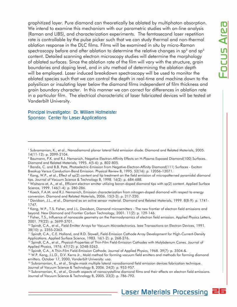
The disperse nature of the precursor is reflected in the resulting LISI layers (Figure 27 and Figure 28). While LISI processing on steel substrates generally led to significant mixing of WC particles within the base material (Figure 27), LISI processing on Stellite 6 resulted in far less diluted WC-containing coatings (Figure 28).
Figure 27 – Cross-sectional view
of a LISI processed steel sample
displaying WC particles dispersed in
the base metal
Figure 28 – Cross-sectional view of a LISI processed Stellite 6 sample displaying WC particles.
Note the reduced dilution of the precursor material with the base material. The LISI layer thickness
is approximately 80 m
WC Particles Binder

18Laser Materials Processing
Focu
s A
reaIn both cases, the WC-containing coatings appear to be metallurgically sound and
fusion bonded to the base material. These results demonstrate the capability of the IPG fiber laser HurryScan30 system to form metallurgically sound cemented carbide-type coatings.
3. Nanodiamond as a Carbon Source in Laser Materials Processing
Nanodiamond powders were investigated as a source of carbon in laser materials processing. First, nanodiamond powders were LISI processed onto AISI 1010 steel using the Hobart 3kW Nd:YAG laser system, producing a 60-100 m thick hardened surface layer composed of martensite and austenite, as suggested by both metallographic (Figure 29) and X-ray diffraction analysis (Figure 30). These results indicate that hardening was achieved by increasing the carbon content of the steel by dissolving the nanodiamond into the iron solution.
Figure 29 – Low carbon steel LISI
processed with nanodiamond. LISI
surface is visible to the left of the
micrograph. The corresponding
hardness distribution is also
shown
Figure 30 – XRD diffractogram reveals the presence of martensite and austenite in the LISI
processed layer

19Laser Materials Processing
Focu
s A
reaPresent work is focused on laser processing mixtures of ball-milled W- nanodiamond
powders for in-situ synthesis of WC. XRD analysis of laser processed powder samples (Figure 31) shows that several tungsten carbides, including WC, form during laser processing of ball-milled W- nanodiamond powders.
Figure 31 – XRD analysis of laser processed ball-milled W- nanodiamond powders
These results clearly illustrate the potential of nanodiamond powders as a source of carbon in laser materials processing.
Tungsten - nanodiamond powders are obtained using a newly installed ball mill (Figure 32) and laser processing is being explored for development of WC 3D cermet parts for high-temperature applications.
Figure 32 –Ball mill for mixing
nanodiamond with refractory metals for
high temperature cermet processing

20Laser Materials Processing
Focu
s A
rea4. Finite Element Modeling of the LISI Process
A three-dimensional finite element heat transfer model (Figure 33) of LISI processing of TiC powders on Al alloy substrates has been developed. This model has been implemented on the ABAQUS finite element software package and uses user-defined sub-routines written in FORTRAN.
Figure 33 – Finite element mesh used to solve the heat transfer problem associated to LISI
processing of TiC powders over Al substrates. The “LISI condition” is also illustrated. The dotted
arrow indicates the laser beam scan direction
Details concerning the specific features of the developed model and the major results from computer runs were reported in a paper presented at the PowderMet2006 Conference, in San Diego, from 19-21 June of 2006 and published in the conference proceedings.
Figure 34 – Temperature field (C) at t 1.2 ms

21Laser Materials Processing
Focu
s A
rea
Figure 35 – Temperature field (C) at t 98.7 ms
Figure 36 – The final material composition map shows a track of TiC/Al composite that is 1.5 mm
wide and 7 mm long, overlaying a 0.3 mm deep TiC-free substrate melt region
The results obtained compare reasonably well with published data4 on experimental LISI trials performed for the same material system. This is somewhat surprising given the “rule of mixtures” treatment of the thermophysical properties of the composite and the small scale of the TiC particles in relation to the finite element mesh.
New Equipment and Software Development
Besides the new ball mill (Figure 32), the HurryScan30 galvo driven scan head was received and put into operation with the IPG fiber laser (Figure 37).
4 P. Kadolkar and N. Dahotre, “Variation of structure with input energy during laser surface engineering of ceramic coatings on aluminum alloys”, Appl. Surf. Sci., 2002, vol. 199, pp. 222-233.

22Laser Materials Processing
Focu
s A
rea
Figure 37 – Detail of the HurryScan30, coupled to the IPG fiber laser
To assist future efforts to develop a laser-based solid freeform fabrication technique for development of three-dimensional cermet parts, a computer program named ZBurn3 (Figure 38) has been developed to control the IPG laser, the HurryScan30 and the U500 multi-axis translation system during laser processing, starting from a CAD file representation of the part to be built.
Figure 38 – PC screen view of the ZBurn3 software
Principal Investigator: Dr. William HofmeisterSponsors: Arnold Engineering Development Center and Center for Laser Applications

23Laser Materials Processing
Focu
s A
reaTechnical Support and Consultation
Service for Fischer USAFischer USA received customer reports from the hydroforming production line that fracture
had occurred in the laser seam welding area of the laser welded 304 stainless steel tubing during hydroforming process as shown in Figure 39 A. CLA staff (Hofmeister, White, Li, Lansford) visited the Fischer laser welding production line to learn more about laser working conditions. Metallurgical characterization and micro-hardness testing of laser welded area in the failed tubing samples was performed by CLA (Figure 39 B and C). The failures in the
hydro formed tubing were attributed to a loss of ductility in the heat affected zone of the weld. This HAZ can be seen in the hardness profiles (Figure 39 C and E) as an area of increased hardness just outside the fusion zone. The microstructure and resulting hardness profiles are, of course, very sensitive to welding and forming parameters. Several iterations with Fischer and UTSI were used to optimize the laser welding process parameters. The final microstructure and hardness data (Figure 39 D and E) are the result of this iterative process. The failures were eliminated.
Figure 39 – Failed tube
samples from Fischer USA
in (A), with corresponding
weld microstructure shown in (B) and micro-hardness testing results in (C). The improved welding
microstructure and micro-hardness distribution is shown in (D) and (E), respectively.
Principal Investigator: Dr. William HofmeisterSponsors: Center for Laser Applications and Fisher USA

24Laser Materials Processing
Focu
s A
reaLaser Patterning of Diamond
MicroelectronicsDiamond possesses unique material properties; high strength, good stability, large
bandgap, excellent thermal conductivity, low absorption cross-section, and high dielectric strength. Diamond surfaces are reported to have a low or negative electron affinity.2,3 Diamond has tremendous potential as an advanced, high temperature electronic material, and considerable research has been conducted to try to capture the benefits of this material system in engineering applications. A large body of this work has been on diamond films grown by chemical vapor deposition (CVD) on planar substrates. These films are commonly referred to as diamond-like carbon films (DLC films), because their polycrystalline nature includes significant sp2 bonded carbon in grain boundary regions.4 These defects structures lower the bandgap from 4.5 eV to below 3 eV.5 Diamond has been successfully doped with p-type elements such as boron, whereas n-type doping has proven elusive.6
The Diamond Microelectronics Group at Vanderbilt uses microwave assisted, plasma
enhanced chemical vapor deposition (MPECVD) to grow micron thick diamond and nanodiamond films. These films have found application as high temperature pressure and chemical sensors,7 and most notably, as electron emitters.8 Professor Hofmeister has worked with Professors Davidson and Kang at Vanderbilt University (VU) to develop diamond emitters for high power and radiation hardened switching applications. A basic premise of this work is the use of nanostructured emission tips. A very tight radius of curvature at the emission tip is known to enhance electron emission by reducing the tunneling barrier to electron emission.9 Diode and triode structures are fabricated at VU in two basic configurations: vertical and lateral. Vertical devices (based on the Spindt-type cathode array10-13) are grown in silicon molds.14 We have achieved currents that scale as high as 100 A/cm2 in small samples with nine diamond tips,5 however, larger planar devices (1 cm2) with millions of tips have been limited to total currents of 100 mA. In an effort to mitigate the problems of closely space anode/cathode arrangements in planar devices and provide switches and emitters for hybrid packages, we have pursued lateral devices as a means to achieve high currents in chip-type architectures.1,15,16
At UTSI Hofmeister has continued collaboration with Davidson and Kang by investigating the fabrication of lateral emitters by photo-machining. This work has been accomplished with J.P. Sercel Associates in New Hampshire using UV excimer lasers. First, a nanodiamond film is grown by CVD on a silicon-on-insulator (SOI) wafer. The current fabrication technique uses photolithography and reactive ion etching to form the structure shown in Figure 40. There is a concern that the chemical species used in RIE could damage the insulating layer of the device and there are also the feature size limitations of the photolithography and etching process. The current UV laser machining approach is promising, but has feature size limitations as well. In the first test of the technique, a line grid of 3 micron spacing was used to photomachine a nanodiamond film. The resulting microstructure is shown in Figure 41.

25Laser Materials Processing
Focu
s A
rea
Figure 40 – Nanodiamond
Microelectronic anode and cathode
formed by RIE on an SOI wafer (ref. 1)
Figure 41 – Nanodiamond film
photomachined with UV eximer laser
using a 3 micron line grid
We hypothesize that pulse shape and polarization engineering can accomplish sub diffraction and diffraction limited focusing of femtosecond laser pulses for machining of feature sizes much smaller than currently achieved. For the emission devices, such as the one in Figure 40, a finer tool will allow devices to be constructed with lower turn-on voltage and less potential damage to the insulating substrate. The techniques practiced in UV mask projection are not applicable to femtosecond machining because the pulse durations are too short for beam homogenization. Therefore, we will use direct write techniques to form patterns on the diamond/SOI substrates.
Because of the durability of diamond and the thickness (>1 micron) of the films, it will be difficult to use sub-diffraction focused light and near field optics for the direct write diamond ablation experiments. Therefore, we must use far-field diffraction limited conditions for high aspect ratio, sub-micron feature construction. One technique will be to use high index fluids at the diamond surface to enhance the temporal focusing of femtosecond pulses.
One of the concerns of optical fabrication is the effect of laser ablation on the diamond film. The most common explanation of the laser ablation mechanism in diamond is that the laser pulse heats diamond to cause graphitization and subsequent pulses remove the
26Laser Materials Processing
Focu
s A
reagraphitized layer. Pure diamond can theoretically be ablated by multiphoton absorption.
We intend to examine this mechanism with our parametric studies with on-line analysis (Raman and LIBS), and characterization experiments. The femtosecond laser repetition rate is controllable by the pulse picker such that we can study thermal and non-thermal ablation response in the DLC films. Films will be examined in situ by micro-Raman spectroscopy before and after ablation to determine the relative changes in sp2 and sp3 content. Detailed scanning electron microscopy studies will determine the morphology of ablated surfaces. Since the ablation rate of the film will vary with the structure, grain boundaries and doping level, and in situ method of determining the ablation depth will be employed. Laser induced breakdown spectroscopy will be used to monitor the ablated species such that we can control the depth in real-time and machine down to the polysilicon or insulating layer below the diamond films independent of film thickness and grain boundary character. In this manner we can correct for differences in ablation rate in a particular film. The electrical characteristic of laser fabricated devices will be tested at Vanderbilt University.
Principal Investigator: Dr. William HofmeisterSponsor: Center for Laser Applications
1 Subramanian, K., et al., Nanodiamond planar lateral field emission diode. Diamond and Related Materials, 2005. 14(11-12): p. 2099-2104.2 Baumann, P.K. and R.J. Nemanich, Negative Electron-Affinity Effects on H-Plasma Exposed Diamond(100) Surfaces. Diamond and Related Materials, 1995. 4(5-6): p. 802-805.3 Bandis, C. and B.B. Pate, Photoelectric-Emission from Negative-Electron-Affinity Diamond(111) Surfaces - Exciton Breakup Versus Conduction-Band Emission. Physical Review B, 1995. 52(16): p. 12056-12071.4 Kang, W.P., et al., Effect of sp(2) content and tip treatment an the field emission of micropatterned pyramidal diamond tips. Journal of Vacuum Science & Technology B, 1998. 16(2): p. 684-688.5 Wisitsora-at, A., et al., Efficient electron emitter utilizing boron-doped diamond tips with sp(2) content. Applied Surface Science, 1999. 146(1-4): p. 280-286.6 Koeck, F.A.M. and R.J. Nemanich, Emission characterization from nitrogen-doped diamond with respect to energy conversion. Diamond and Related Materials, 2006. 15(2-3): p. 217-220.7 Davidson, J.L., et al., Diamond as an active sensor material. Diamond and Related Materials, 1999. 8(8-9): p. 1741-1747.8 Kang, W.P., T.S. Fisher, and J.L. Davidson, Diamond microemitters - The new frontier of electron field emissions and beyond. New Diamond and Frontier Carbon Technology, 2001. 11(2): p. 129-146.9 Fisher, T.S., Influence of nanoscale geometry on the thermodynamics of electron field emission. Applied Physics Letters, 2001. 79(22): p. 3699-3701.10 Spindt, C.A., et al., Field-Emitter Arrays for Vacuum Microelectronics. Ieee Transactions on Electron Devices, 1991. 38(10): p. 2355-2363.11 Spindt, C.A., C.E. Holland, and R.D. Stowell, Field-Emission Cathode Array Development for High-Current-Density Applications. Applied Surface Science, 1983. 16(1-2): p. 268-276.12 Spindt, C.A., et al., Physical-Properties of Thin-Film Field-Emission Cathodes with Molybdenum Cones. Journal of Applied Physics, 1976. 47(12): p. 5248-5263.13 Spindt, C.A., A Thin-Film Field-Emission Cathode. Journal of Applied Physics, 1968. 39(7): p. 3504-&.14 W.P. Kang, J.L.D., D.V. Kerns Jr., Mold method for forming vacuum field emitters and methods for forming diamond emitters. October 17, 2000, Vanderbilt University: usa.15 Subramanian, K., et al., Single-mask multiple lateral nanodiamond field emission devices fabrication technique. Journal of Vacuum Science & Technology B, 2006. 24(2): p. 953-957.16 Subramanian, K., et al., Growth aspects of nanocrystalline diamond films and their effects on electron field emissions. Journal of Vacuum Science & Technology B, 2005. 23(2): p. 786-792.

27Laser Materials Processing
Focu
s A
rea
Laser Induced Hierarchical Calcium Phosphate Structures
The surface properties of biomedical implant materials contribute to the dynamic interactions at tissue-implant interfaces. Increasing understanding of the complexity in hierarchical assembly of natural hard tissues has been applied to synthetic materials. Presumably, the nano scale features influence protein and chemical interactions, the micro scale features effect cell orientation, and meso scale features provide surfaces for tissue integration. In the present work laser surface engineering is used to demonstrate a multi-scale surface for bioactive functions. A Ti alloy surface was pre-coated calcium phosphate and laser processed and laser with 850 W power and processing speeds ranging from 0.021 m/s-1 to 0.041 m/s-1 in ambient air. A multi dimensional organization of bioactive calcium phosphate coating with multiple phases was obtained on the Ti-alloy substrate.
The morphology of the laser processed coating consisted of Ti rich and Ca-P deficient
star-like phases distributed inside a Ca-P rich cellular structure as shown in Figure 42 and 43. The cellular structures ranged in diameter from 2.5 m to 10 m, while the cell boundaries were composed of cuboid shaped particles of dimensions of ~200 nm x 1 μm. The elemental analysis based on electron dispersion spectroscopy (EDS) revealed that the star-like structure ‘A’ is Ti rich and Ca-P deficient (Figure 42b) where as ‘B’ is a Ca-P rich region (Figure 42c). Furthermore, XRD analysis [of the coating] (Figure 42d) revealed the presence of CaO, -TCP (Tri Calcium Phosphate), CaTiO3, TiO2, along with Ti.
Figure 42 – Morphological
and Chemical characterization
of the laser processed surface
is illustrated here. Figure (a)
Scanning electron image of a
sample of laser processed surface
showing multi features. (b) EDS
spectra taken on Region A (c)
EDS taken on Region B (d) XRD
spectrum of the surface

28Laser Materials Processing
Focu
s A
reaPresumably, the rapid cooling associated with the laser processing resulted in formation of
the Ca-P rich glassy phase into a micron scale cellular morphology with submicron clusters of CaTiO3 phase precipitated inside the cellular structures as shown schematically in Figure 44.
Figure 43 – This series
of scanning electron
micrographs reveals the
multi-scale texture evolved
in the laser processed
coating. The multi-scale
structure consists of
star shaped features
distributed inside a cellular
structure
The solidification of the coating into multiscale structure has been influenced by chemical and physical interactions among the multiphases evolved during laser processing. These interactions may include of glass formation, particle cluster assembly due to physical forces, periodic cluster assembly due to dipole interactions and cellular assembly of periodic clusters due to hydrodynamic drag, surface tension and capillary forces.
Figure 44 – Proposed evolution of microstructure in the molten pool at high temperatures is shown
schematically. The following figures show the various stages during microstructural evolution. (a)
Mineral Calcium phosphate (dark) phases floating in molten Ti. The arrows indicate the direction
of migration of Ca-
P rich phases. (b)
Segregation into Ca-
P rich and deficient
regions (c) nucleation
of CaTiO3
(a) (b) (c)

29Laser Materials Processing
Focu
s A
reaIt is important to understand the biocompatibility of each of the chemical species
that is produced as a result of the high temperature interaction and solidification. Lima et al. have shown that osteoblast proliferation was significant on nano structured and nano phase materials.1 The current surface also exhibited the presence of micro scale CaTiO3 and Webster et al. have revealed that there was increased osteoblast adhesion on materials that contained CaTiO3 than those containing both pure hydroxyapatite and uncoated titanium.2 At much higher length scale corresponding to the glassy CaP-TiO2 there exists sufficient literature which states that by modifying the composition of glass ceramics, specifically incorporating metallic oxides like TiO2 the degradation rate in a bio-environment can be controlled for desired dissolution. Thus the material systems containing phases such as CaO, P2O5, and TiO2 may to have ostecompatibility. On the whole the multiple phases produced in the current processing are biocompatible and when coupled with their multi scale nature they are expected to improve their osteoconductivity.
Principal Investigator: Dr. Narendra B. DahotreSponsor: Center for Laser Applications
1 Lima, R.S., Khor, K.A., Li, H., Cheang, P., Marple, B.R., HVOF Spraying of Nanostructured Hydroxyapatite for Biomedical Applications, Mat. Sci. and Eng. A 205; 396: 181-187. 2 Webster, T. J., Ergun, C., Doremus, R.H., Lanford, W.A., Increased Osteblast Adhesion on Titanium-coated Hydroxylapatite and Forms CaTiO3. J. Biomed. Mater. Res. A 2003; 67: 975-80.
Laser Surface Processing of Ti6Al4V in Gaseous Nitrogen forBiomedical Applications
Among titanium alloys, Ti6Al4V is extensively used for biomedical applications due to its mechanical and electrochemical properties. Vanadium, a constituent of this alloy, has been reported to cause undesirable biological reactions. Electrochemical and corrosive wear in physiological solutions is considered to be a source of vanadium emission from implant in the patient. The normally good corrosion resistance, of Ti6V4A can be reduced by damage to the passive film. A low repassivation rate results in delay of film repair on the surface.
Surface modification is a recognized method to improve the metal/alloy surface
to enhance the interfacial properties for accelerated implant-host response. Various surface modification methodologies such as plasma ion implantation, laser melting and laser surface alloying, physical and chemical vapor deposition (PVD and CVD), thermal oxidation, electrochemical surface modification/ anodizing, have been used to improve wear, corrosion, and fretting resistance of orthopaedic implant materials including Ti6Al4V. The motivation of laser alloying of titanium alloys with nitrogen is primarily due to the

30Laser Materials Processing
Focu
s A
reabiocompatibility of the resultant titanium nitride and the increase in wear resistance. Some
work has been carried out on laser surface alloying with nitrogen that showed significant changes in the performance such as wear and hardness of functional surface. This study focused on nitrogen surface alloying with varying laser traverse velocities and powers to improve corrosion and wear resistance for bio-implant applications. Additionally, the effect of pH on laser-processed Ti6Al4V was investigated as implant encounters a wide range of pH from 4.0 – 9.0 in various parts/ organ (such as blood, urine, saliva, interstitial fluid, perspiration) of the body.
This work was carried out to understand the effects of laser scan speed on corrosion, microstructure and hardness of surface of nitrogen alloyed Ti6Al4V. A 2.5 KW Hobart continuous wave Nd:YAG laser was used to alloy the surface of Ti6Al4V with nitrogen. Corrosion performance of laser formed surface was evaluated by anodic polarization in Ringer’s physiological solution.
Increase in laser scanning speed was found to reduce the thickness of alloyed zone from 258 to 87 m over the range tested. The structure of laser-modified surface contains dendrites grown normal to the laser direction, over a basket-weave structure of acicular (martensite) (Figure 45). Hardness at the top surface of laser-processed at 500 mm/min was ~1137 Hv which was reduced with increase in the laser scan speed (577 Hv at 1500 mm/min). Laser surface processing shifted the corrosion potential of Ti6Al4V toward noble side as compared to untreated alloy; the maximum shift by ~ 484 mV was recorded at pH~9 solution. Passivation after laser surface modification was improved as currents were approximately < 1/3 times the untreated Ti6Al4V in passive region. The pitting resistance of untreated material was found to increase from 1.84 - 2.5 V with pH. Pitting potential was observed to decrease after laser treatment (Figure 46).
Figure 45 – Microstructure of Ti6Al4V
laser-processed at 500 mm/min
A
B
50 μm 5μm
10μm

31Laser Materials Processing
Focu
s A
rea
Figure 46 – Anodic polarization curves
of Ti6Al4V in Ringer’s solution of pH (a)
4.0, (b) 7.4, and (c) 9.0
Principal Investigator: Dr. Narendra B. DahotreSponsor: Center for Laser Applications
Non-equilibrium Modeling of Microstructure Evolution in RapidSolidification of Laser Dressed Alumina Grinding Wheels
Surface engineering is the modification and design of a surface to improve heat resistance, wear resistance, hardness or some other desirable property. Laser surface modification is a non-equilibrium process involving high cooling rates (103 -108 K/s). In this work we studied the physical processes underlying the microstructural evolution in

32Laser Materials Processing
Focu
s A
reaceramic materials during interactions with such an intense and well defined infrared heat
source. This microstructural aspect of the laser assisted surface dressing of ceramic for machining application has not been addressed in the literature, even though the studies on performance evaluation of the laser process on machining of ceramic is well documented. Most of the characterization of the laser dressed grinding wheels is limited to surface roughness measurements. In the work we studied the evolution of the microstructure within laser surface modified alumina and its relation to laser dressing parameters. A constitutive model was formulated to predict the effects of laser fluence on the evolution of grain structure (Figure 47). These predictions were then compared with the actual grain size (radius) measured from micrographs (Figure 48a). The grain size could be easily predicted from this empirical model. The processing parameters and hence the cooling rate was altered to achieve the desired microstructure. Prediction and control of evolution of desired microstructure (grain size) through such modeling efforts is significant for dressed ceramic wheel in grinding and/or machining.
Figure 47
– Flowchart for the
steps in obtaining
the empirical relation
for maximum grain
radius A three
dimensional model was created in FEMLAB to model Fourier’s second law of heat transfer. The peak temperature reached during the process is a function of the laser fluence, the cooling rate, and the temperature distribution. The final microstructure varies with the cooling rate. Macro/microscopic models of solidification were combined using the microenthalpy method to predict the recalescence phenomena and the effect of the laser fluence on the magnitude of recalescence was estimated (Figure 48b). The main advantage which an enthalpy formulation offers is that any solidification path is characterized by a decreasing enthalpy.
It was observed that the cooling rate reduced as the fluence increased. There is a continuous deterioration of grains through decrease in the number of cutting edges and vertices as the grinding takes place. Hence an estimate of the grain density would be important to control the laser dressing parameters to generate the desired number of grains that need to be replenished on the surface.

33Laser Materials Processing
Focu
s A
rea
Figure 48 – a) Grain radius measured from micrographs .b) Modeled cooling curves for different
laser fluences exhibiting recalescence
Principal Investigator: Dr. Narendra B. DahotreSponsor: Center for Laser Applications
Laser Cladding of Fe-Cr-Mo-Y-B-C Bulk Metallic Glass on Steel Substrate
Bulk metallic glasses (BMG) are the amorphous alloys formed when the liquid of certain alloy composition is quenched rapidly so that the atoms freeze into a non-crystalline arrangement. Extensive research efforts have been made in the past two decades primarily by Japanese- and US- scientists, since the development of first metallic glass of Au75Si25 by Duwez at Caltech in 1960.1 These alloys, in the absence of crystalline structure, offer unique properties such as high tensile strength and hardness, high corrosion resistance, and good wear resistance.
In spite of the attractive properties offered by the bulk metallic glasses, their actual utilization in industrial applications remained limited due to difficulties in obtaining the bulk quantities and limitations in thickness achieved by rapid quenching techniques such as melt spinning. Significant efforts have been directed towards obtaining the coatings of amorphous alloys on the bulk substrates. Some interest has been directed towards utilization of laser cladding technique for surface amorphization. Due to rapid cooling rates associated with laser processing accompanied with the alloy compositions with high GFA, laser cladding offers the potential to achieve the amorphous surfaces by suppressing the crystallization.

34Laser Materials Processing
Focu
s A
reaThe present efforts are directed towards investigating the microstructure and properties
of the laser clad Fe48Cr15Mo14Y2C15B6 alloy on the steel substrate from the precursor amorphous powder. A 2.5 kW Hobart continuous wave Nd:YAG laser equipped with a fiber optic beam delivery system was employed for laser cladding of amorphous coating on steel substrate. Laser processing was carried out at 1500 W and 2000 W with the linear scan speed of 100, 200 and 300 cm/min at each power.
Figure 49 shows the XRD patterns of amorphous alloy powder and the laser clad layer for the laser powers of 1500 W at laser scan speeds of 350 and 275 cm/min. The XRD patterns show the appearance of the crystalline peaks superimposed on the amorphous background in all the laser processed samples. The crystalline peaks in the diffraction patterns of laser clad layers primarily corresponds to the -Fe and (Fe, Cr, Mo)7C3. Figure 50 presents the variation of thickness of clad layer as a function of laser scan speed for two different powers i.e., 1500 and 2000 W. For the same power the coating thickness decreases with the increasing laser scan speed due to decreased penetration of the heat into the precursor alloy powder. Also, the specimens processed with 2000 W shows greater thickness of the coatings compared with that obtained using 1500 W with the same laser scan speed.
Figure 49 – XRD patterns of (a) precursor amorphous powder and laser clad coatings at laser
parameters (b) 1500 W and 350 cm/min and (c) 1500 W and 275 cm/min

35Laser Materials Processing
Focu
s A
rea
Figure 50 – Cladding
layer thickness as a
function of laser scan
speed for 1500 and
2000 W
The laser cladding of amorphous composition on the steel substrate is associated with marked improvements in the properties such as greater surface hardness and wear resistance. Figure 51 indicates that for each laser power of 1500 W, increase in laser scan speed results in higher surface hardness, whereas, the depth of penetration of the higher hardness is less compared to that obtained using the lower laser scan speeds. Figure 52 also provides the wear behavior of laser clad and substrate steel. The figure clearly shows the better wear performance of the laser clad specimens processed at laser scan speed of 100 and 200 cm/min at both the powers i.e., 1500 and 2000 W. The specimens processed at 300 cm/min at both the laser powers show the greater material removal than that of the substrate especially during the initial period of the test due to rough sample surface.
Figure 51 – Microhardness of
laser clad Fe43
Cr16
Mo16
C15
B10
coatings with laser power of
1500 W
Surface cladding of Fe-based amorphous powders resulted in crystalline phases at the surface and under these conditions an amorphous layer was not formed. The increase in hardness and wear properties is a result of the crystalline phases, particularly the carbides in the surface layer.

36Laser Materials Processing
Focu
s A
reaFigure 52 – Weight loss of the
laser clad layer as function of time
during the wear test conducted at
constant load of 38 N
Principal Investigator: Dr. Narendra B. DahotreSponsor: Center for Laser Applications
1 P. Duwez, R. H. Wilens, W. Klement, Continuous Series of Metastable Solid Solutions in Silver-copper Alloys. Journal of Applied Physics, 31 (1960) 1136-1137.
Laser Surface Modifications of Alumina Grinding Wheels for Micro-scale Material Removal
Alumina ceramics are traditionally used in the manufacture of wheels for surface grinding applications. The wheel surfaces are subjected to high material removal rates and frictional heat generation leading to loss of dimensional stability and effective number of cutting edges in the wheel surface in addition to poor form tolerance and the appearance of surface and subsurface defects in the ground products. The most important step in the grinding process is the restoration of cutting efficiency of the wheels by periodical re-sharpening of the wheels using a diamond dresser, which mechanically removes material from the surface of the wheel and thus exposes the new abrasive grains for cutting action. Even though conventional diamond dressing is still used extensively in industrial grinding practice, the operation has its own demerits. This includes the uncontrolled fracture of the bond material and break-off of abrasive grains. Also, it has been reported that 90% of the wheel material is removed in the dressing operation thus increasing the consumable costs in addition to the costs of process down-time for the dressing operation. Lasers can be efficiently used as flexible tools for the surface dressing of grinding wheels. The advantages offered by this non-contact process include ease of automation, improved productivity and consistent quality of wheel surface topography.
The laser dressing results in substantial grain refinement at the surface in addition to the appearance of a characteristic morphology of the surface grains (Figure 53). The refinement of the surface grains is a result of the high cooling rates associated with rapid solidification. The surface grains have a wide range of size distributions; however, the

37Laser Materials Processing
Focu
s A
rea
shape of the surface grains is regular with well-defined edges and vertices. The laser dressed grinding wheels are not completely free of porosity and exhibit distributed micro pores between the multifaceted surface grains (Figure 53b) which can be helpful for the micro-scale precision machining by collecting the microparticles removed during machining and also the removed tips of faceted surface grains of laser dressed grinding wheel.
Figure 53 – SEM
micrographs of
alumina specimen
(a) before and (b)
after laser dressing
The effects of laser irradiation on the surface microstructure of the alumina ceramic are illustrated in Figure 54. The figure presents a set of SEM surface micrographs corresponding to the untreated alumina substrate (Figure 54a) and laser surface modified alumina at laser fluence of 458-687 Jcm-2. (Figure 54b-2h). The untreated substrate consisted of irregular alumina grains with a high degree of interconnected porosity. The surface modification of such highly porous alumina substrate with high power laser resulted in highly dense surface microstructure marked by systematic development of surface morphologies as a function of laser fluence. It is evident that the surface microstructure of laser modified alumina ceramic is characterized by faceted polygonal surface grains with varying sizes and extent of surface faceting depending on laser fluence. In general, the polygonal surface grain size (average of diagonal dimensions) increased with increasing laser fluence. This is a direct consequence of decreasing cooling rate with increase in laser fluence. This general trend of increase in grain size with increasing laser fluence (i.e., decreasing cooling rate) is in agreement with the established solidification theories.
Figure 54 – SEM
micrographs of
surface of (a)
untreated alumina
substrate; and laser
surface modified
alumina at laser
fluence of (b) 458,
(c) 496, (d) 535, (e)
573, (f) 611, (g) 649, and (h) 687 Jcm-2

38Laser Materials Processing
Focu
s A
rea Detailed x-ray analysis revealed stable -Al2O3 phase in both the substrate and laser
surface modified specimens. Further analysis of the x-ray spectra revealed a systematic variation of relative intensities of (1 1 0) and (1 0 4) planes with laser fluence. The substrate showed a strongest peak corresponding to (1 0 4) reflection in agreement with the standard randomly oriented reference pattern. In laser processed samples, the relative intensity of (1 1 0) reflection increased progressively with laser fluence up to 573 Jcm-2 followed by a gradual decrease above the fluence of 573 Jcm-2 (Figure 55). Thus, there existed an intermediate value of laser fluence (573 Jcm-2) which showed strongest (1 1 0) peak and weak (1 0 4) peak.
Figure 55 – Relative intensity of (1 1 0) reflection (2 37.785 deg) of -Al2O3 substrate and
laser surface modified alumina with various laser fluences The understanding of the evolution of the characteristic crystal shapes at the
intermediate laser power can be correlated with the development of crystallographic texture from the viewpoint of van der Drift model.1 The model considers that each crystallite or grain grows with each crystallographic facet moving with a known normal velocity until a facet meets the surface of another growing crystallite. The grain boundaries are thus formed when the surfaces of different grains impinge upon each other. The evolution of the faceted morphology then depends on the relative growth velocities of the various facets. From the above discussion, in the context of laser surface modification of alumina ceramic the evolution of (1 1 0) texture may be related with the relative growth of (1 1 0) planes in hexagonal lattice. A schematic of the formation of faceted crystal from the intersection of {1 1 0} and {2 1 1} planes in hexagonal lattice is presented in Figure 56. The corresponding shape is compared with the SEM micrograph of the faceted morphology of the surface grains in laser surface modified alumina ceramic.

39Laser Materials Processing
Focu
s A
rea
Figure 56 – Schematic of the development of faceted morphology from crystallographic texture in
laser surface modified alumina
Principal Investigator: Dr. Narendra B. DahotreSponsor: Center for Laser Applications
1 A. V. D. Drift, Evolutionary Selection: A Principle Governing Growth Orientation in Vapour-deposited Layers, Philips Research Reports, 22 267-288 (1967).
40
Introduction
Laser spectroscopy has been and continues to be a major area of research in the Center of Laser Applications capabilities. In the early days the technique was focused on measuring flows in combustion experiments and in plasma diagnostics. Currently, CLA has a nationally recognized program in single molecule spectroscopy and continues to lead research in femtosecond laser induced breakdown spectroscopy.
Focus
Area
Ultrasensitive Fluorescence Spectroscopy
41Ultrasensitive Fluorescence Spectroscopy
Focu
s A
rea
Ultrasensitive Fluorescence Spectroscopy
Ultrasensitive laser spectroscopy has become essential for a number of present day research ventures, including nano-photonics, bio-photonics, bio-materials, and forefront biotechnology and molecular biology research. CLA is well poised to contribute to these highly interdisciplinary endeavors. We have developed a multifaceted program that builds on our earlier accomplishments, which include contributions to the first experiment to detect single fluorescent molecules in aqueous solution, to the first spectroscopic measurements on single molecules in aqueous solution, including single-molecule fluorescence lifetime determinations, to the development of the high quantum-efficiency single-photon avalanche-diodes (SPADs) that are now widely used in ultrasensitive spectroscopy, to the first single-molecule detection within a miniaturized lab-on-a-chip device, to single-DNA sequencing-by-synthesis research, and to fluorescence fluctuation diagnostics for high-throughput screening in pharmaceutical drug discovery. In the past year, our research has encompassed theoretical, computational, and experimental developments in fundamental physical understanding and in practical implementation of new measurement techniques.
Present research funding includes grants from Abbott Laboratories and from the National Institutes of Health (NIH), and in the past year new proposals have been submitted to the NIH, NSF, DARPA, and DoD. Several of these proposals have involved collaborations between Prof. Lloyd Davis (Physics) and Prof. William Hofmeister (Materials Science). Other collaborators include Prof. Narendra Dahotre (CLA), Prof. Bruce Bomar (UTSI), Profs. William Hamel and Vijay Chellaboina (UT Knoxville), Dr. Claus Daniel (ORNL), Profs. Steven Soper, Robin McCarly, and Jost Goettert (Louisiana State University), Prof. Prescott Deininger (Tulane University), Profs. John Wikswo, Deju Li, Anthony Forster and Ray Mernaugh (Vanderbilt University), Profs. Andy Ellington, George Georgiou, Brent Iverson and Dmitrii Makarov and Dr. Casey Cole (University of Texas at Austin), and Prof. Gerard Marriott (University of Wisconsin-Madison).
In the past 12 months, 1 CLA doctoral student (David Ball) has graduated, 2 new students have joined the group (Will Robinson and James Aiken), several of CLA’s new postdoctoral associates have initiated research in collaborative projects in this area (Dr. Yelena White, Dr. Zbigniew (Peter) Sikorski, and Dr. Xiaoxuan (Shaun) Li), and one former CLA postdoctoral associate (Dr. Guoqing (Paul) Shen) has been promoted to research scientist, with partial funding from the NIH. Research collaborations in ultrasensitive laser spectroscopy have continued with Prof. David Piston (Vanderbilt University), Prof. Mona Wells (Tennessee Tech University), Prof. Ki-Huan Li (Konju National University, Korea), and Dr. Hans Blom (Royal KTH Institute, Stockholm, Sweden).

42Ultrasensitive Fluorescence Spectroscopy
Focu
s A
rea
New Methodology for Fluorescence Correlation Spectroscopy
In most physical measurements, noise is to be avoided, but in the technique of fluorescence correlation spectroscopy (FCS), a careful characterization of noise provides a means for the determining the kinetics of a system, without requiring that the system be displaced from its equilibrium situation. FCS was first invented in the early 1970’s to measure chemical kinetics of systems at equilibrium, but the usefulness of early experiments was limited. However, following improvements in signal-to-background, with technical developments such as the demonstration of single-molecule detection in solution, the use of confocal microscopy to reduce the sample volume to femtoliter size, and the incorporation of high quantum-efficiency single-photon avalanche-diode (SPAD) detectors, the technique has now become widespread for routine bioscience investigations.
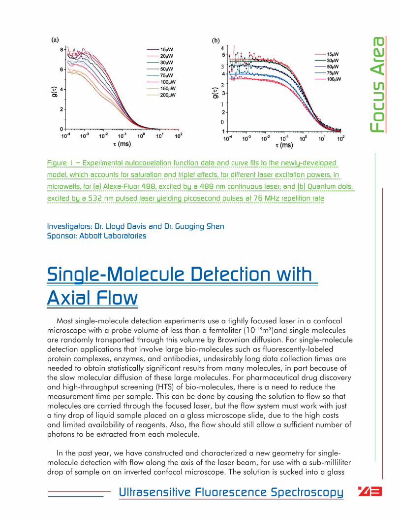
In FCS, the timescale of the noise is captured in the autocorrelation function of the fluorescence fluctuations. A model fit to the normalized autocorrelation then yields the concentrations of different molecules and information on their kinetics. The theoretical models for fitting the autocorrelation, developed from the early days of FCS, do not contain any dependence on the laser power, but experiments clearly show laser-power dependence, even as the laser power is asymptotically decreased to zero. Because FCS has become an increasingly important tool for assaying biophysical systems, there is considerable interest in removing systematic errors from measurements. Our numerical simulations of single-molecule detection and FCS have shown that excitation saturation and transitions of molecules to metastable triplet levels cause a non-linear laser-power-dependence in the rate at which fluorescence photons can be emitted, which leads to the observed power dependence in the autocorrelation function. We derived a new theoretical model of the autocorrelation that includes these non-linearities, and we also devised a new and useful method for correcting for the power dependence of the autocorrelation, by first performing calibration measurements of the average photon count rate versus power. Details of the theoretical model and practical implementation for improved FCS measurements were reported in an invited paper in Current Pharmaceutical Biotechnology. Figure 1 shows examples of experimental data collected in our lab at different laser powers, together with fits to our new theoretical model of FCS.
43Ultrasensitive Fluorescence Spectroscopy
Focu
s A
rea
Figure 1 – Experimental autocorrelation function data and curve fits to the newly-developed
model, which accounts for saturation and triplet effects, for different laser excitation powers, in
microwatts, for (a) Alexa-Fluor 488, excited by a 488 nm continuous laser; and (b) Quantum dots,
excited by a 532 nm pulsed laser yielding picosecond pulses at 76 MHz repetition rate
Investigators: Dr. Lloyd Davis and Dr. Guoging ShenSponsor: Abbott Laboratories
Single-Molecule Detection with Axial Flow
Most single-molecule detection experiments use a tightly focused laser in a confocal microscope with a probe volume of less than a femtoliter (10-18m3)and single molecules are randomly transported through this volume by Brownian diffusion. For single-molecule detection applications that involve large bio-molecules such as fluorescently-labeled protein complexes, enzymes, and antibodies, undesirably long data collection times are needed to obtain statistically significant results from many molecules, in part because of the slow molecular diffusion of these large molecules. For pharmaceutical drug discovery and high-throughput screening (HTS) of bio-molecules, there is a need to reduce the measurement time per sample. This can be done by causing the solution to flow so that molecules are carried through the focused laser, but the flow system must work with just a tiny drop of liquid sample placed on a glass microscope slide, due to the high costs and limited availability of reagents. Also, the flow should still allow a sufficient number of photons to be extracted from each molecule.
In the past year, we have constructed and characterized a new geometry for single-molecule detection with flow along the axis of the laser beam, for use with a sub-milliliter drop of sample on an inverted confocal microscope. The solution is sucked into a glass

44Ultrasensitive Fluorescence Spectroscopy
Focu
s A
reacapillary positioned above the ellipsoidal confocal volume, as schematically shown in
Figure 2. Molecules traverse the longest axis of the ellipsoid, and hence provide greatest photon yield. Our experimental measurements showed that decreased spacing between
the capillary tip and laser focus gives increased flow speed, as measured by fluorescence correlation spectroscopy, but also increased background from capillary autofluorescence. However, for appropriate spacing, this background can be removed by a spatial filter, permitting single-molecule detection with very good signal-to-background ratio, as seen in Figure 3. Experiments were also performed with two-photon excitation using a femtosecond Titanium Sapphire laser. We demonstrated that flow can alleviate localized triplet and photobleaching effects of the molecules, and speed single-molecule sampling rates for fluorescence fluctuation spectroscopy determinations of slowly-diffusing biomolecules, in pharmaceutical drug discovery research. The results of this research have been submitted for publication in Applied Optics and are also reported in the dissertation of David Ball, who has graduated with a Ph.D. in physics this Fall 2006.
Figure 2 – Schematic of CLA apparatus for single-molecule
detection with capillary-induced flow along the laser axis
Figure 3 – Photon bursts from a 50 pM
solution of Alexa Fluor 594, obtained
with the capillary 50 m from the laser
focus
Investigators: Dr. Lloyd Davis, Dr. Guoging Shen, and Mr. David BallSponsor: Abbott Laboratories
45Ultrasensitive Fluorescence Spectroscopy
Focu
s A
reaSingle-Molecule Trapping
Whereas flow can speed certain bioassays, in many single-molecule biophysics experiments, it is desired to prolong the observation time so that an individual biomolecule can be observed for an extended duration, in order to study its dynamical behavior. For example, in a recent DARPA program to develop technology to sense and control the conformation or folding-state of an isolated bio-defense protein, it is essential to hold a single protein molecule in place for up to about 1 second, while measurements and molecular control are performed. Tethering of the protein to a surface is not acceptable as it can modify the biomolecule properties. Similarly, laser trapping, which has been demonstrated to be effective for micron-sized particles, is not acceptable for single protein molecules, as the trapping force scales with the cube of the particle diameter and is inadequate to trap such small nano-meter sized biomolecules. In the past year, we have initiated research on new methods to hold a small single molecule immobile against the forces of Brownian diffusion. This work is included in CLA contributions to a large collaborative proposal to DARPA, and it will be incorporated in other proposals in the year ahead.
We have studied the use of active feedback of electrophoresis and electro-osmosis forces to return the molecule back to the origin, to counteract Brownian diffusion. In contrast to laser trapping, these forces are so strong that the trapping strength is instead limited by the latency of the position sensing and active feedback. We have designed a novel method for fast sensing of the molecular position to reduce the delay time of the feedback. Under the direction of Prof. L. Davis, CLA postdoctoral associate Dr. Y. White has performed preliminary experiments with our Tsunami Ti-Sapphire laser to create an illumination profile for the fast molecular position sensing. CLA graduate research associate W. Robinson has performed MatLab calculations of the laser illumination and is creating a new ab initio computer simulation of the process written in C++. CLA postdoctoral associate Dr. Z. Sikorski has performed numerical calculations of electrokinetic forces for 3-dimensional trapping using multiphysics software. Figure 4 shows an example in which voltages are applied to four electrodes surrounding the laser focal region, to produce forces along the field lines. Computations addressed the uniformity of the force field and revealed that low voltages of several Volts are adequate for the single-molecule trap. CLA graduate research associate J. Aiken is bringing into operation a new Titanium Sapphire laser that will be used in the trapping experiments. Also, we have made progress on the fabrication of micro-fluidic and nano-fluidic sample cells for the trapping of single molecules, as described elsewhere in this report. We expect the active trapping of single molecules will enable many new biotechnology applications.

46Ultrasensitive Fluorescence Spectroscopy
Focu
s A
rea
Figure 4 – Electrophoretic field lines produces
by voltages on four electrodes, with background
colored by electric potential
Investigators: Dr. Lloyd Davis, Dr. Yelena White, Dr. Zbigniew Sikorski, Mr. William Robinson, and Mr. James AikenSponsor: Center for Laser Applications
Maximum Likelihood Multi-Channel Photon-Counting Microscopy
Multi-dimensional imaging, in which detailed spectroscopic information is collected at each pixel, is a developing tool that has already enabled breakthrough results in biophysical research. Commercial microscopes are now available with software for “linear unmixing” that can routinely resolve fluorescent species with overlapping emission spectra. With support from the National Institute of Biomedical Imaging and Bioengineering at the National Institutes of Health, we are working to extend such capabilities to ultrasensitive fluorescence microscopy applications, where photon shot noise must be carefully accounted for in the analysis.
In the past year, we have completely rebuilt our single-molecule microscope. We have developed a new custom-designed microscope, which is shown during its construction in Figure 5. The microscope incorporates our two tunable-wavelength picosecond dye lasers, shown in Figure 6, for sample excitation. The pulse trains of each laser are interleaved, and time-resolved single photon detection is used to identify which laser excitation wavelength gives rise to each photon. The laser beams are introduced into the microscope by use of angle-tuned reflection from narrow-band Raman notch filters. This enables epi-illumination, in which the beams are focused into the sample with the same microscope objective that is used for fluorescence light collection, and it also provides strong rejection of scattered light at the laser wavelengths. We achieve diffraction-limited confocal imaging, and use a 3-dimensional piezo-electric nano-translation stage for scanning of the sample to acquire an image. At each pixel of the image, the collected photons pass through a custom-built adjustable prism spectrometer, for high-throughput resolution of the fluorescence into 4 spectral bands. A fiber-optically coupled 4-channel high-
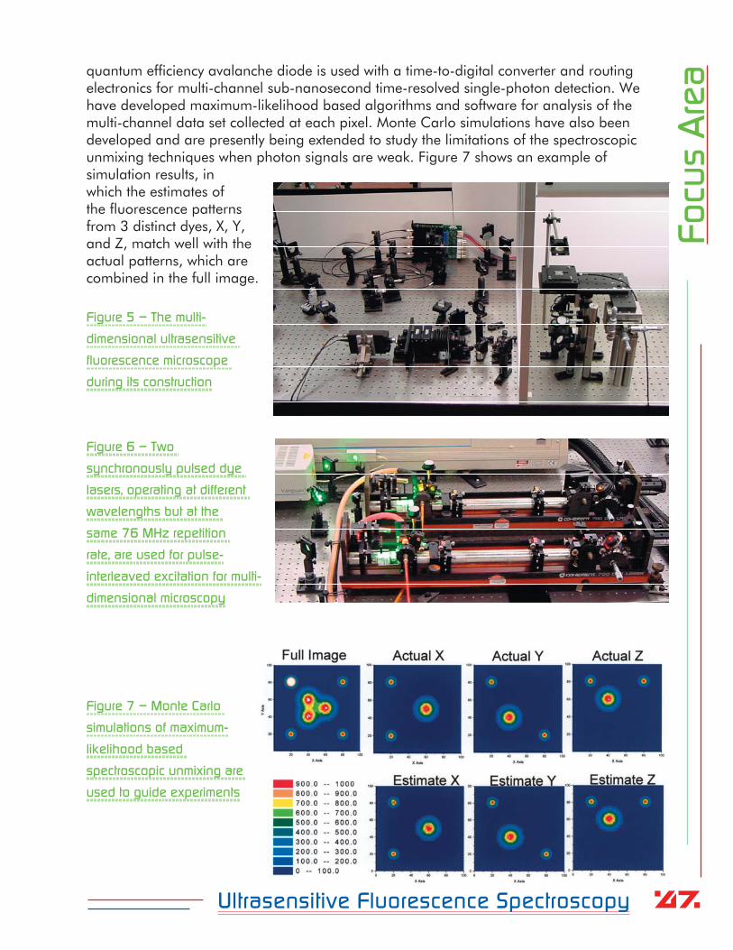
47Ultrasensitive Fluorescence Spectroscopy
Focu
s A
reaquantum efficiency avalanche diode is used with a time-to-digital converter and routing
electronics for multi-channel sub-nanosecond time-resolved single-photon detection. We have developed maximum-likelihood based algorithms and software for analysis of the multi-channel data set collected at each pixel. Monte Carlo simulations have also been developed and are presently being extended to study the limitations of the spectroscopic unmixing techniques when photon signals are weak. Figure 7 shows an example of simulation results, in which the estimates of the fluorescence patterns from 3 distinct dyes, X, Y, and Z, match well with the actual patterns, which are combined in the full image.
Figure 5 – The multi-
dimensional ultrasensitive
fluorescence microscope
during its construction
Figure 6 – Two
synchronously pulsed dye
lasers, operating at different
wavelengths but at the
same 76 MHz repetition
rate, are used for pulse-
interleaved excitation for multi-
dimensional microscopy
Figure 7 – Monte Carlo
simulations of maximum-
likelihood based
spectroscopic unmixing are
used to guide experiments

48Ultrasensitive Fluorescence Spectroscopy
Focu
s A
reaOur research aims to provide extended sensitivity for a number of imaging applications
in biomedical research, including high-speed multiplexed read-out of bio-chips, rapid DNA sequencing, fluorescence lifetime imaging microscopy, and cell imaging experiments that require separation of fluorescent labels with overlapping excitation and/or emission spectra, such as green fluorescent protein and its variations. We are collaborating on applications of our new techniques to cell imaging experiments that use intrinsic fluorescent proteins with Professor David Piston of the Molecular Physiology & Biophysics Department at Vanderbilt University. The results of our research to date will be presented on September 26, 2006, at the Fifth Inter-Institute Workshop on Optical Diagnostic Imaging from Bench to Bedside at the National Institutes of Health. This research will continue in the year ahead.
Investigators: Dr. Lloyd Davis, Dr. Guoging Shen, and Mr. William RobinsonSponsor: National Institutes of Health
Computer Modeling and SimulationsA key component of our research has been the development of Monte Carlo simulations
to help in the interpretation of experimental data, and to evaluate experimental limitations, operating parameters, and data analysis strategies. In the previous year we developed a fast new ab initio simulation of single-molecule detection and fluorescence correlation spectroscopy (FCS), using LabView and C software. This past year, we have used these programs to improve our understanding of several experiments, including studies of saturation and triplet photophysics in FCS, and single-molecule detection with axial flow. We have recently rewritten parts of the program in C++ in order to extend the simulation to evaluate single-protein-molecule trapping and spectroscopy experiments, and this work will continue in the year ahead.
Several other advanced computer codes were developed in the past year, and multi-physics simulations were performed to provide preliminary data in support of research proposals, evaluate new ideas, and get quantitative data for experimental design. This work has been performed in large part by Dr. Z. Sikorski, an experienced computational physicist, who joined CLA as a postdoctoral research associate in April of this year from CFD Research Corporation. Figure 8 presents an example of computations of electro-osmotically driven fluidic flow lines at the intersection to two rectangular micro-channels in a lab-on-a-chip device to be used for single-molecule experiments.
Figure 8 – Electroosmotic flow lines at the intersection of
fluidic channels
Investigators: Dr. Lloyd Davis, Dr. Guoging Shen, Dr. Zbigniew Sikorski, and Mr. William RobinsonSponsors: Abbott Laboratories and Center for Laser Applications

49Ultrasensitive Fluorescence Spectroscopy
Focu
s A
reaPolarization-Engineered Microscopy
Recent experiments in the literature have shown that a laser beam with a radially-patterned polarization profile can be focused with a high numerical aperture microscope objective to a spot size that is ~ 65% of that achievable with a linearly polarized beam, as shown schematically in Figure 9. A wide range of microscopic imaging applications are limited to far-field optical access, but would benefit considerably even from modest improvements in spatial resolution. During the past year, we have begun investigations on the use of engineered profiles of laser beam polarization, both to improve the spatial resolution in single-molecule studies, and also to improve the fidelity of polarization-resolved fluorescence measurements with high-numerical aperture optics. We have developed codes in MatLab and have performed theoretical and numerical investigations to study the effects of particular input vector field profiles on the resulting field patterns about the focal point, for given numerical aperture. The axial symmetry of the radially-polarized doughnut mode illumination beam, shown in Figure 10a and b, results in cancellation of the transverse electric field component at the focal point. However, constructive interference due to the symmetry leads to a strong longitudinal or axial field component at the focal point. This high intensity spike is surrounded by a doughnut-shaped intensity pattern of lower intensity that has radial polarization. The width of the central spike can be as low as one-half of the diffraction limited spot size, as shown in Figure 10c. In the laboratory, we have used a liquid crystal device to create a radially-polarized laser beam, and we plan to
use this in the year ahead in our single-molecule studies.
Figure 9 – Schematic comparison
of focusing of a linearly-polarized
laser beam and a radially-polarized
doughnut mode
Figure 10 – CLA’s numerical simulations show (a) the intensity, and (b) the polarization, of the
illumination beam; and (c) the longitudinal, radial, and total field components at points in the focal
plane, as a function of the distance from the axis
Investigators: Dr. Zbigniew Sikorski, Dr. Yelena White, and Dr. Lloyd Davis,Sponsor: Center for Laser Applications

50Ultrasensitive Fluorescence Spectroscopy
Focu
s A
rea
High-Efficiency Single-Photon Detection with Picosecond Timing Resolution
Early experiments in single-molecule spectroscopy used photomultiplier tubes with less than 10% single-photon detection efficiency and achieved very limited signal levels. Soon after, CLA initiated a collaboration with EG&G Optoelectronics, Canada, to help develop photon counting modules with > 65% efficiency, and these modules are now used world-wide in most present day ultrasensitive fluorescence spectroscopy and fluorescence correlation spectroscopy experiments. We have continued this collaboration over the years, and during the past year, we have worked to test and improve the performance of new prototype modules, particularly for applications that require picosecond-resolved single-photon timing. In the past year, we have also performed measurements with a detector and timing electronics provided by another vendor, Micro Photon Devices, Inc., as shown in Figure 11. This detector was found to give superior timing performance, but the detection efficiency was found to be inferior, particularly for applications with red-wavelength fluorescent species. Perkin Elmer, which acquired EG&G Optoelectronics, has provided us with a red-sensitive multi-channel detector for further study, and in the year ahead, they plan to provide other modified units for collaborative studies.
Figure 11 – MPD single-photon detector
Investigators: Dr. Lloyd Davis and Dr. Guoging ShenSponsor: Center for Laser Applications, with hardware provided by MPD and Perkin Elmer
Femtosecond Laser DevelopmentsMany experiments in ultrasensitive fluorescence spectroscopy work best with two-
photon excitation using a femtosecond Titanium Sapphire laser, in large part because the non-linear excitation mechanism localizes the excitation to occur only at the laser focus, rather than along the entire laser beam. For much of the past year, we have used a Spectra Physics Tsunami Titanium Sapphire laser in several of our experiments, but recently we have undertaken replacement of this laser with another cost-effective kit-set

51Ultrasensitive Fluorescence Spectroscopy
Focu
s A
realaser manufactured by KMLabs. This laser, which
is shown in Figure 12, provides pulses with a broad-band spectrum exceeding 100 nm. It is currently being brought into operation by CLA graduate research assistant Mr. J. Aiken. We plan to use the large spectral bandwidth in future experiments to control the chirp or frequency sweep and the pulse shape to provide control of non-linear excitation mechanisms.
Figure 12 – Mr. James Aiken adjusts the KMLabs
femtosecond Titanium-Sapphire laser
Investigators: Dr. Lloyd Davis, Dr. Yelena White, Mr. James Aiken, and Dr. William HofmeisterSponsor: Center for Laser Applications
Other Activities in the Ultrasensitive Fluorescence Spectroscopy Focus Area
Much of our research conducted in ultrasensitive fluorescence spectroscopy also falls within the general area of Chemical Physics and over the past year CLA has continued its involvement with the UT Center in Chemical Physics (http://www.phys.utk.edu/chemphys.htm). CLA graduate research assistant Mr. David Ball attended the annual three-day workshop in Chemical Physics held at Knoxville in February 2005. This past year, the Chemical Physics Center also awarded a $500 travel grant to support continued collaborative research with Professor Mona Wells, from Tennessee Technological University, on ultrasensitive fluorescence detection for bio-availability and bio-sensing. In our collaboration this past year, several sets of measurements were conducted using CLA’s single-molecule detection apparatus and using extracts from e-coli bacteria cells genetically engineered at Tennessee Tech to express intrinsic fluorescent proteins in response to the sensing of bio-available pollutants. This is a nascent area that is expected to have important applications in environmental sensing.

52Ultrasensitive Fluorescence Spectroscopy
Focu
s A
reaCollaboration with Professor Ki-Hwan Lee, of Kongju National University, South Korea,
who spent his sabbatical leave with CLA from August 2004 to August 2005, has also been continued over the past year. Professor Lee visited CLA again during August 2006 to perform further experimental measurements on the photoluminescent properties of nano-structured silicon surfaces. Collaborations are also continuing with Dr. Hans Blom, of the KTH (Kungliga Teknishka Hogskolan—Royal Institute of Technology) in Stockholm, Sweden, on total-internal reflection fluorescence correlation spectroscpy.
Several aspects of our research on numerical modeling and Monte Carlo simulations were incorporated into the Physics 642 Computational Physics course taught by Prof L. Davis during fall 2005, and practical details of single-photon counting and correlations were incorporated into the Physics 610 Quantum Optics course taught during Spring 2006. Quantum Optics is a research area with great vitality, and it is pleasing to note that the 2005 Nobel Prize in Physics was awarded in part to Prof. Roy Glauber from Harvard University for his contributions to Quantum Optics and to the theory of photon correlation functions, which are now central to fluorescence correlation spectroscopy.
Laser-Induced Breakdown Spectroscopy
Applications of ultra-short laser radiation in materials science continued to be of interest at the Center for Laser Applications. Research efforts focused on characterizing interaction of intense femto-second to nano-second radiation with materials and gases. The study of laser-induced aluminium plasma shows applications in micro-machining. Nominal nano-second pulses from Q-switched lasers have found a volley of uses in laser machining. Further, carbon plasmas are of central importance in modern nanotechnology as these plasmas are used for generating carbon nanostructures such as fullerenes, carbon nanotubes and artificial diamonds.
Collaboration with the Chemical Research Center in Budapest, Hungary, continued to address the chemical an physical processes taking place in carbon plasma that are known to be very complex. Synthesis routes of large carbon structures are addressed by investigating occurrence and spectroscopic measurement of the C3 molecule. This international collaboration effort follows past extensive emission spectroscopy measurements at the Center for Laser Applications and current theoretical analyses of the C2 radical in laser-induced plasma. For the experimental efforts, nominal nano-second Q-switched infrared (1064-nm) laser radiation was used with a fluence of typically 2 J/cm2. The measurements of C3 spectra were investigated both with focused and unfocused laser radiation incident on graphite, and for a variety of background gases.
In the study of laser-induced aluminium plasma, time-resolved spectroscopy is utilized in measurements of micro-plasma generated by focusing Nd:YAG laser radiation onto an aluminium block in laboratory air and in gaseous mixtures that include hydrogen.

53Ultrasensitive Fluorescence Spectroscopy
Focu
s A
reaApplication of atomic spectroscopy allows one to determine electron number densities as
high as 1019 cm-3 from measurements of Stark-widths and shifts of the hydrogen Balmer-alpha series. An example of this spectroscopy is shown in Figure 14. Characterization of the aluminum plasma, following optical breakdown of solid aluminium, shows electron number densities of typically 0.5 x 1019 cm-3 early in the plasma decay.
Figure 14 – Recorded Spectra of
Stark profiles – aluminium block in
laboratory air. A number density of
Ne 1017 cm-3 is inferred 1-s after
optical breakdown in air, using here a
100-ns gate width
In detailed studies we use 150 mJ, 8-ns laser pulses with a peak irradiance of 1 TW/cm2. This peak irradiance corresponds to an electric field strength of E = 1/100 x 2.8GV/cm, or 1/100 of the field strength that holds the hydrogen atom together. Hydrogen Balmer series lines are used to infer the number density of aluminium expanding into a cell filled with 125 Torr of hydrogen (see Figure 15).
Figure 15 – Recorded Stark
widths and shifts for Al I
394.40-nm and Al I 396.15-
nm lines. A number density of
Ne 3 x 1018 cm-3 is inferred
by comparison with Ha
profiles 100-ns after optical
breakdown in a cell filled with
125 Torr of hydrogen. Here, a
6-ns gate width was used
The inferred number densities and temperatures are consistent with values reported in the literature, however, spatial resolution over and above the employed temporal resolution will be desirable in future studies of the plasma. In our studies of the plume near the aluminium block, we also used measurements of the hydrogen beta line up to number densities of 1 x 1018 cm-3 which is to our knowledge the highest ever recorded from hydrogen-beta Balmer series line measurements as shown in Figure 16 and Table 1.
Wavelength [nm]Int
ensity
[a.u.]
393 394 395 396 397 3980
2000
4000
6000
8000
10000
delay = 100 ns
Wavelength [nm]
Rel
ativ
eIn
tens
ity
394 395 396 397 3980
1000
2000
3000
4000 0.45 μs0.75 μs1 μs1.5 μs
Al I
Al I

54Ultrasensitive Fluorescence Spectroscopy
Focu
s A
rea
Figure 16 – Recorded Stark widths
and shifts for hydrogen-beta Balmer
series line
TABLE 1. Line width (FWHM) and peak separation for
= 486.14 nm H Balmer series line
Analysis of the measured profiles included continued collaborative efforts with researchers at Auburn University. The results were presented at the 18th international conference of spectral line shapes (ICSLS). Furthermore, collaborative efforts in the study of laser-induced breakdown spectroscopy (LIBS) lead to contribution of a chapter by Dr. Parigger in a first comprehensive reference book on LIBS.
Principal Investigator: Dr. Christian PariggerSponsor: Center for Laser Application
Wavelength [nm]
Inte
nsity
[a.u
.]
470 480 490 5000
200
400
600
800
1000
1200
delay =200 ns
Wavelength [nm]
Inte
nsity
[a.u
.]
470 480 490 5000
200
400
600
800
1000
1200
delay =150 ns
Wavelength [nm]
Inte
nsity
[a.u
.]
470 480 490 5000
200
400
600
800
delay =175 ns
Wavelength [nm]
Inte
nsity
[a.u
.]
470 480 490 5000
50
100
150
200
250
300delay =400 ns
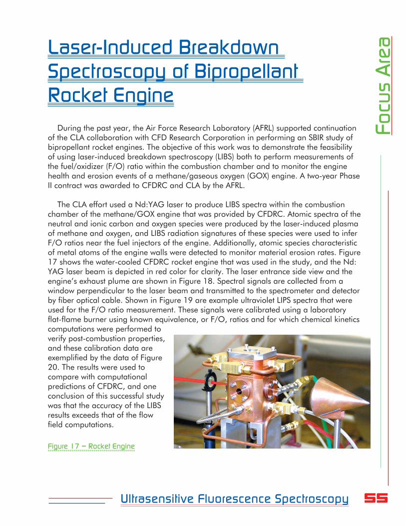
55Ultrasensitive Fluorescence Spectroscopy
Focu
s A
reaLaser-Induced Breakdown
Spectroscopy of Bipropellant Rocket Engine
During the past year, the Air Force Research Laboratory (AFRL) supported continuation of the CLA collaboration with CFD Research Corporation in performing an SBIR study of bipropellant rocket engines. The objective of this work was to demonstrate the feasibility of using laser-induced breakdown spectroscopy (LIBS) both to perform measurements of the fuel/oxidizer (F/O) ratio within the combustion chamber and to monitor the engine health and erosion events of a methane/gaseous oxygen (GOX) engine. A two-year Phase II contract was awarded to CFDRC and CLA by the AFRL.
The CLA effort used a Nd:YAG laser to produce LIBS spectra within the combustion chamber of the methane/GOX engine that was provided by CFDRC. Atomic spectra of the neutral and ionic carbon and oxygen species were produced by the laser-induced plasma of methane and oxygen, and LIBS radiation signatures of these species were used to infer F/O ratios near the fuel injectors of the engine. Additionally, atomic species characteristic of metal atoms of the engine walls were detected to monitor material erosion rates. Figure 17 shows the water-cooled CFDRC rocket engine that was used in the study, and the Nd:YAG laser beam is depicted in red color for clarity. The laser entrance side view and the engine’s exhaust plume are shown in Figure 18. Spectral signals are collected from a window perpendicular to the laser beam and transmitted to the spectrometer and detector by fiber optical cable. Shown in Figure 19 are example ultraviolet LIPS spectra that were used for the F/O ratio measurement. These signals were calibrated using a laboratory flat-flame burner using known equivalence, or F/O, ratios and for which chemical kinetics computations were performed to verify post-combustion properties, and these calibration data are exemplified by the data of Figure 20. The results were used to compare with computational predictions of CFDRC, and one conclusion of this successful study was that the accuracy of the LIBS results exceeds that of the flow field computations.
Figure 17 – Rocket Engine

56Ultrasensitive Fluorescence Spectroscopy
Focu
s A
rea
Figure 18 – Rocket Plume
Figure 19 – Single-Shot LIBS
Rocket Data
Wavelength (nm)
Rel
ativ
eIn
ten
sity
*10
0(a
.u.)
245 250 2550
5
10
15
20
25
30
35
40
45
100 ns after laser
100 ns gate
LIBS in O2 flow
LIBS in CH4 flow
single shot LIBS
O+
C
C+
C+++
O++O+
O+
O+

57Ultrasensitive Fluorescence Spectroscopy
Focu
s A
rea
245 250 255 2600
1
2
3
4
5
6
7
8
9
10
11
pure oxygen flow
Φ = 0.25
Φ = 0.5
Φ = 0.75
Φ = 1.0
Φ = 1.25
Φ = 1.5
Φ = 1.75
Φ = 2.0
pure CH4 flow
<--
-C
H4
/ O2
equi
vale
nce
ratio
---
LIBS in CH4 / O2 combustion
C(1S-1P0)
C+
O++
O+(2P-2D0)
O+
Wavelength (nm)
O+
7 mm above McKenna burner200-300 ns
Rel
ativ
eIn
ten
sity
Figure 20 – McKenna Burner
Calibration Results
The Phase II program will extend the innovations to include a laser source that will be used for both laser-induced ignition of the engine and for subsequent LIBS F/O ratios and engine health monitoring. A coaxial laser beam injector and LIBS collection optical fiber system will be employed, and both methane/GOX and methane/liquid oxygen mixtures will be studied. A Department of Defense safety inspection of the CLA laboratory areas has been conducted prior to initial engine operations.
Investigators: Dr. Ying-Ling Chen, Dr. James W. L. Lewis, and Mr. Jim Hornkohl Sponsors: Air Force Research Laboratory and Center for Laser Applications

58
Focu
s A
rea
Focus
Area
NanofabricationIntroduction
The national research portfolio has shifted in recent years to things very small. Fueled by Richard Feynman’s quote, “There is plenty of room at the bottom,” the National Nanotechnology Initiative has spawned such efforts as the Department of Energy’s investment in nanotechnology centers. Lasers have particular parts to play in the nano world, both in sensing (as is evidenced in the previous section on ultrasensitive spectroscopy) and in fabrication. At CLA we plan to use our new amplified, femtosecond source to create nanochannels and photonic structures by multiphoton processing. We will also use more conventional nanofabrication techniques to create nanochannels to support our single molecule spectroscopy work. These activities will take place in CLA’s new clean room scheduled for completion by the end of calendar 2006.

59Nanofabrication
Focu
s A
rea
Nanofluidics for Single Molecule Sensing and ManipulationIntroduction
Single molecule spectroscopy techniques, discusses in the previous section, enable the observation of the real-time dynamic behavior of single protein molecules. In particular, SMS by Laser Fluorescence Spectroscopy (LFS) has become an important tool in interpretation of protein conformation and has broad potential applications in areas of biomolecular science, drug research, biosensors, genomics and fundamental biophysics. Currently, SMS studies are limited to dilute aqueous solutions to satisfy the constraints of Poisson statistical counting. Investigators have recognized the advantages of using micro and nanofluidics coupled with SMS. Because biomolecules within cells are often confined to nanodomains, or molecularly crowded environments, a detailed understanding of nanodomain molecular physics is very important to a thorough comprehension of in vivo molecular biophysics and the workings of cellular processes. The overall goal of this project is fabrication of nanofluidics to support the LFS study of proteins trapped in such devices. This will enable studies of (i) how nanometer-scale confinement will alter the dynamical, photophysical, and statistical behavior of individual molecules in aqueous solutions, and (ii) how to use electrodynamics to hold and manipulate protein molecules in nanospace for electrical and spectroscopic measurements. We plan to use both “conventional” planar fabrication techniques as well as multiphoton ablation to create nanochannels.
Planar Fabrication
As part of an interdisciplinary research team, CLA is collaborating with Vanderbilt University, UTK and Oak Ridge National Lab to facilitate research on nanofluidics fabrication and LFS investigation using such nanofluidics. A Center for Nanophase Materials Sciences (CNMS) User Proposal was approved and funded by Oak Ridge National Lab. This allows CLA to take advantage of the nanoscience research facilities and staff at CNMS to fabricate and characterize nanochannels in the nanofluidics. The team is comprised of Dr. William Hofmeister, Director of CLA, who is experienced in the fabrication and analysis of micro and nanoscale devices and is mainly responsible for supervision of nanofabrication and device assembly; Dr. Lloyd Davis, a pioneer and expert in Single Molecule Detection is responsible for laser fluorescence spectroscopy; Dr. John Wikswo (Vanderbilt University) is an expert in the construction, instrumentation, and integration of microfluidics devices and will perform nano-fluidic device testing; Dr. Deyu Li (Vanderbilt University) has experience in nanoscale fabrication and nanoscale transport property measurement; Dr. Narendra Dahotre (UTK/ORNL) is an expert in laser materials processing and structural analysis and is responsible for characterization;

60Nanofabrication
Focu
s A
rea
Dr. Claus Daniel, a Wigner fellow at ORNL, is responsible for characterization of nanochannels. Other collaborators include Dr. Xiaoxuan (Shaun) Li, a postdoctoral fellow at CLA focusing on nanochannels fabrication, thermal bonding, assembly and testing of devices; Dr. Guoqing (Paul) Shen, a research scientist of CLA works on laser fluorescence spectroscopy; Dr. Yingfeng Guan, a postdoctoral researcher at UTK is helping develop photolithography and reactive ion etching of samples.
Preliminary experiments have been carried out in the following areas: (i) microchannels were fabricated in fused silica, quartz, soda lime and boron silicate glass by wet chemical etch (Buffered Oxide etch or BOE, ORNL and CLA) and dry chemical etch (Reactive Ion Etch or RIE, ORNL) in a photolithography process; (ii) nanochannels connecting microchannels were machined on fused silica using Focused Ion Beam (FIB, Vanderbilt); (iii) glass substrate with microchannels and blank glass was thermally bonded to make a device (CLA); and (iv) electric resistivity of microchannel device are being tested (CLA and Vanderbilt).
1. Microchannels and Nanochannels Fabrication
Microchannels of 30-100 3-10 m (width depth) were fabricated by Buffered Oxide Etch (BOE 6:1) and Reactive Ion Etch (CHF3/O2, 75/7) respectively in a photolithography process. The morphology of a single microchannel in fused silica glass was evaluated using an AFM (ORNL) to characterize channel geometry and surface morphology. Figure 1A is the AFM measurement result of a RIE microchannel in fused silica glass, with microchannel profile curve shown in the inset. It can be seen that the channel has a near-rectangular geometry, with some irregularity features, e.g. grooves and humps (also see Figure 1C) on the microchannel surface, which is likely due to heterogeneity of the material. Vanderbilt University’s Focused Ion Beam was used to fabricate nanochannels. During FIB machining, a 50 nm chrome layer was on the sample surface for electrical conductivity. Figure 1B show the overview of FIB machined plateau area with nanochannels (on chrome layer) across to connect 2 microchannels. The microstructure of FIB machined plateau between 2 microchannels is shown in Figure 1C. In order to verify that nanochannels were fabricated in fused silica, the chrome layer was removed and a dual-beam SEM/FIB at ORNL was used to section and image the FIB processed plateau area to reveal the cross section of the nanochannels. Shown in Figure 1D, nanochannels of 90 90 nm were fabricated successfully in fused silica using FIB nanomachining.
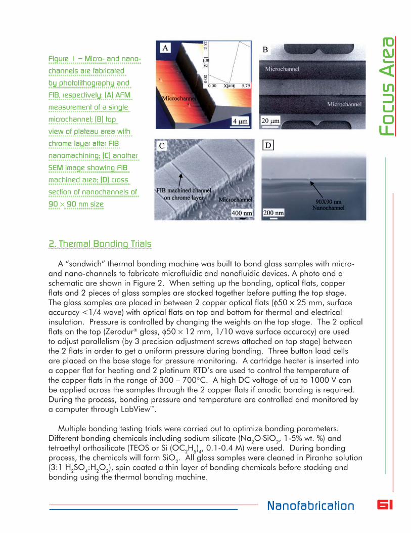
61Nanofabrication
Focu
s A
rea
Figure 1 – Micro- and nano-
channels are fabricated
by photolithography and
FIB, respectively: (A) AFM
measurement of a single
microchannel; (B) top
view of plateau area with
chrome layer after FIB
nanomachining; (C) another
SEM image showing FIB
machined area; (D) cross
section of nanochannels of
90 90 nm size
2. Thermal Bonding Trials
A “sandwich” thermal bonding machine was built to bond glass samples with micro- and nano-channels to fabricate microfluidic and nanofluidic devices. A photo and a schematic are shown in Figure 2. When setting up the bonding, optical flats, copper flats and 2 pieces of glass samples are stacked together before putting the top stage. The glass samples are placed in between 2 copper optical flats (50 25 mm, surface accuracy <1/4 wave) with optical flats on top and bottom for thermal and electrical insulation. Pressure is controlled by changing the weights on the top stage. The 2 optical flats on the top (Zerodur glass, 50 12 mm, 1/10 wave surface accuracy) are used to adjust parallelism (by 3 precision adjustment screws attached on top stage) between the 2 flats in order to get a uniform pressure during bonding. Three button load cells are placed on the base stage for pressure monitoring. A cartridge heater is inserted into a copper flat for heating and 2 platinum RTD’s are used to control the temperature of the copper flats in the range of 300 – 700C. A high DC voltage of up to 1000 V can be applied across the samples through the 2 copper flats if anodic bonding is required. During the process, bonding pressure and temperature are controlled and monitored by a computer through LabView.
Multiple bonding testing trials were carried out to optimize bonding parameters. Different bonding chemicals including sodium silicate (Na2OSiO2, 1-5% wt. %) and tetraethyl orthosilicate (TEOS or Si (OC2H5)4, 0.1-0.4 M) were used. During bonding process, the chemicals will form SiO2. All glass samples were cleaned in Piranha solution (3:1 H2SO4:H2O2), spin coated a thin layer of bonding chemicals before stacking and bonding using the thermal bonding machine.

62Nanofabrication
Focu
s A
rea
Figure 2 – The thermal bonding machine, with a schematic drawing is shown at right
3. Microfluidics Device Fabrication and Testing
After thermal bonding, Nanoports were attached to the glass samples with pre-drilled holes in the fluidic wells (at the ends of the microchannels) on the samples. A syringe was connected to the ports through tubings to inject aqueous solution into the device for testing. As an example, a microfluidics device (Figure 3A) was fabricated from two pieces of soda lime glass sandwiched together. Each piece has a channel of 50×10 μm (width × depth) etched by BOE 6:1 into one face, with the two faces meeting so that the channels intersect at the middle (see 2 insets in Figure 3A). The device was flushed using de-ionized water (Figure 3B) and subjected to electronic property testing, Figure 3C, where 4 electrodes were used to apply 4 DC voltages coupled with AC pulses for the purpose of measuring electric resistivity of the solution in the channel.

63Nanofabrication
Focu
s A
rea
Figure 3 – (A) A fabricated microfluidics device with a schematic of 2 microchannels facing each
other shown in an inset; (B) the postdoctoral researcher Xiaoxuan (Shaun) Li is flushing the device,
which is in a Class 100 clean hood; (C) experimental setup on testing electronic property of the
device, where 4 DC voltages coupled with AC pulses are being applied (also see the inset in A)
Laser Fabrication
The Spectra Physics Tsunami laser has been relocated for use with a new Coherent Regenerative amplifier system, RegA-9000, which is currently being brought into operation by CLA postdoctoral research associate Dr. Yelena White. The regenerative amplifier system, shown in Figure 4, will provide femtosecond laser pulses with sufficient microjoule pulse energies for laser breakdown and direct-write laser machining applications. Femtosecond laser materials processing is a relatively new research area that promises to enable significant new capabilities, including the creation of photonic and fluidic devices: waveguides, couplers and fluidic channels, information storage and optoelectronic systems. This is due in part to the extreme peak irradiances, which initiate strong non-linear coupling mechanisms only very close to the central peak of the focused laser spot, and also in part to the avoidance of thermally-driven phenomena that can degrade resolution. Normally, fused silica shows only slight linear absorption at Ti:Sapphire laser wavelengths (700 — 950 nm). However, when ultrashort laser pulses are tightly
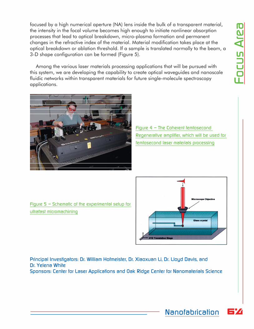
64Nanofabrication
Focu
s A
reafocused by a high numerical aperture (NA) lens inside the bulk of a transparent material,
the intensity in the focal volume becomes high enough to initiate nonlinear absorption processes that lead to optical breakdown, micro-plasma formation and permanent changes in the refractive index of the material. Material modification takes place at the optical breakdown or ablation threshold. If a sample is translated normally to the beam, a 3-D shape configuration can be formed (Figure 5).
Among the various laser materials processing applications that will be pursued with
this system, we are developing the capability to create optical waveguides and nanoscale fluidic networks within transparent materials for future single-molecule spectroscopy applications.
Figure 4 – The Coherent femtosecond
Regenerative amplifier, which will be used for
femtosecond laser materials processing
Figure 5 – Schematic of the experimental setup for
ultrafast micromachining
Principal Investigators: Dr. William Hofmeister, Dr. Xiaoxuan Li, Dr. Lloyd Davis, and Dr. Yelena WhiteSponsors: Center for Laser Applications and Oak Ridge Center for Nanomaterials Science

65
Focu
s A
rea
Focus
Area
Nonequilibrium Fluid Physics
IntroductionIn prior years, the nonequilibrium fluid physics focus area included research in
electromagnetic railguns and plasma space propulsion devices such as arcjet thrusters, ion engines, Hall thrusters, pulse plasma thrusters, and laser-sustained plasma thrusters. Advanced plasmas diagnostics were utilized in these programs to characterize plasma and fluid conditions to gain a better understanding of the detailed physical processes occurring within them. Laboratory work was often accompanied by meticulous computer simulations.
Current programs in the nonequilibrium fluid physics area build largely on plasma propulsion expertise gained in the prior work mentioned above. For instance, a project to characterize and model a novel pulsed plasma thruster was completed this year. An effort to model the laser ablation of a propellant in a miniature thruster concept being developed for microsatellites was also completed this year. In addition, a program to develop a highly sensitive electric propulsion thrust stand for the Arnold Engineering and Development Center (AEDC) commenced this year. Finally, the Hypersonic Vehicle Electric Power System program to develop MHD generators for the U.S. Air Force completed its third year of funding. These programs are detailed below.
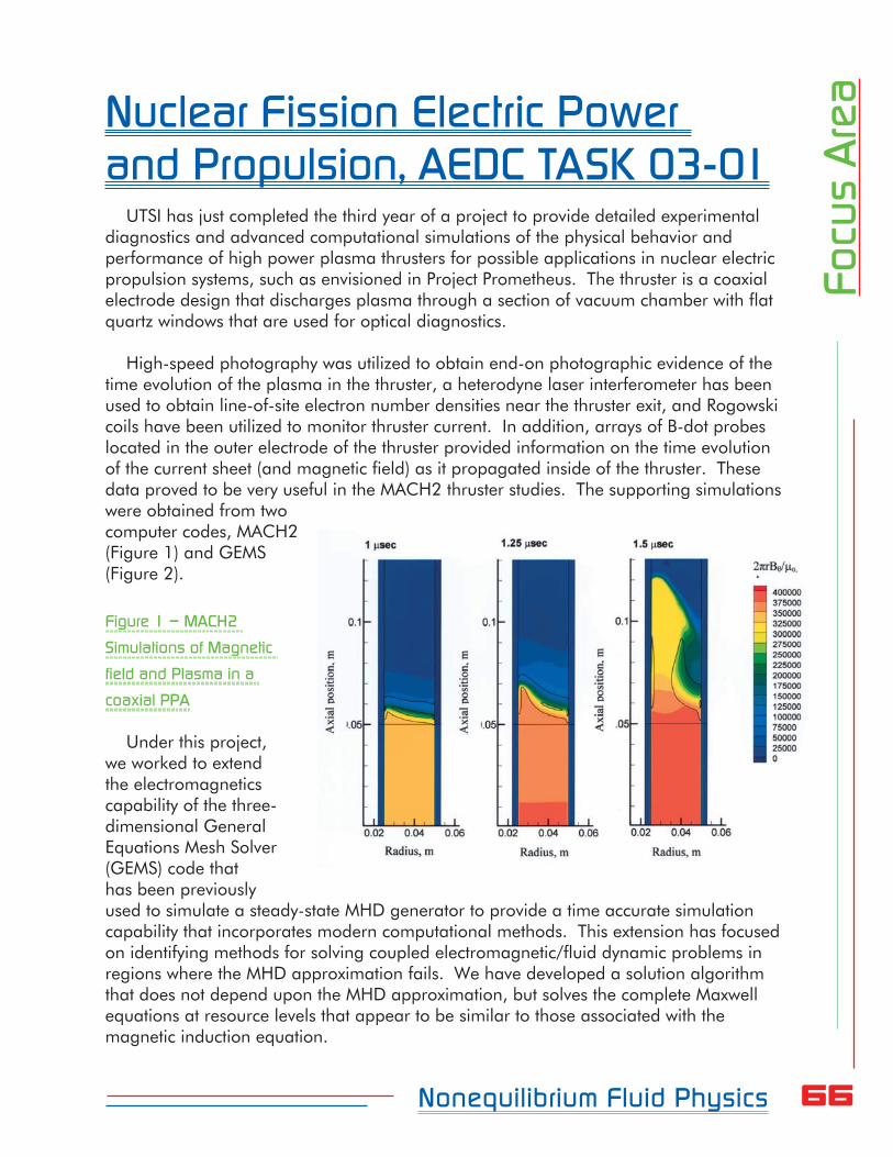
66Nonequilibrium Fluid Physics
Focu
s A
reaNuclear Fission Electric Power
and Propulsion, AEDC TASK 03-01UTSI has just completed the third year of a project to provide detailed experimental
diagnostics and advanced computational simulations of the physical behavior and performance of high power plasma thrusters for possible applications in nuclear electric propulsion systems, such as envisioned in Project Prometheus. The thruster is a coaxial electrode design that discharges plasma through a section of vacuum chamber with flat quartz windows that are used for optical diagnostics.
High-speed photography was utilized to obtain end-on photographic evidence of the time evolution of the plasma in the thruster, a heterodyne laser interferometer has been used to obtain line-of-site electron number densities near the thruster exit, and Rogowski coils have been utilized to monitor thruster current. In addition, arrays of B-dot probes located in the outer electrode of the thruster provided information on the time evolution of the current sheet (and magnetic field) as it propagated inside of the thruster. These data proved to be very useful in the MACH2 thruster studies. The supporting simulations were obtained from two computer codes, MACH2 (Figure 1) and GEMS (Figure 2).
Figure 1 – MACH2
Simulations of Magnetic
field and Plasma in a
coaxial PPA
Under this project, we worked to extend the electromagnetics capability of the three-dimensional General Equations Mesh Solver (GEMS) code that has been previously used to simulate a steady-state MHD generator to provide a time accurate simulation capability that incorporates modern computational methods. This extension has focused on identifying methods for solving coupled electromagnetic/fluid dynamic problems in regions where the MHD approximation fails. We have developed a solution algorithm that does not depend upon the MHD approximation, but solves the complete Maxwell equations at resource levels that appear to be similar to those associated with the magnetic induction equation.
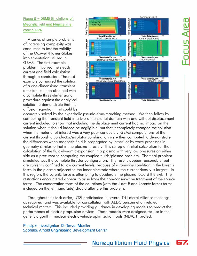
67Nonequilibrium Fluid Physics
Focu
s A
reaFigure 2 – GEMS Simulations of
Magnetic field and Plasma in a
coaxial PPA
A series of simple problems of increasing complexity was conducted to test the validity of the Maxwell/Navier-Stokes implementation utilized in GEMS. The first example problem involved the steady current and field calculation through a conductor. The next example compared the solution of a one-dimensional transient diffusion solution obtained with a complete three-dimensional procedure against the analytical solution to demonstrate that the diffusion equation limit could be accurately solved by the hyperbolic pseudo-time-marching method. We then follow by computing the transient field in a two-dimensional domain with and without displacement current included to show that including the displacement current had no impact on the solution when it should indeed be negligible, but that it completely changed the solution when the material of interest was a very poor conductor. GEMS computations of the current through a conductor/insulator combination were then computed to demonstrate the differences when magnetic field is propagated by ‘ether’ or by wave processes in geometry similar to that in the plasma thruster. This set up an initial calculation for the calculation of the fluid-dynamic expansion in a plasma with very low pressures on either side as a precursor to computing the coupled fluids/plasma problem. The final problem simulated was the complete thruster configuration. The results appear reasonable, but are currently confined to low current levels, because of a runaway condition in the Lorentz force in the plasma adjacent to the inner electrode where the current density is largest. In this region, the Lorentz force is attempting to accelerate the plasma toward the exit. The restrictions encountered appear to arise from the non-conservative treatment of the source terms. The conservation form of the equations (with the J-dot-E and Lorentz forces terms included on the left hand side) should alleviate this problem.
Throughout this task order, UTSI participated in several Tri-Lateral Alliance meetings, as required, and was available for consultation with AEDC personnel on related technical matters. This included providing guidance in developing models to predict the performance of electric propulsion devices. These models were designed for use in the genetic algorithm nuclear electric vehicle optimization tools (NEVOT) project.
Principal Investigator: Dr. Trevor MoellerSponsor: Arnold Engineering Development Center

68Nonequilibrium Fluid Physics
Focu
s A
reaVertical EP Thrust Stand for 12V
Vacuum Chamber, AEDC TASK 03-01
The first year of a three-year effort to develop a vertical thrust stand was conducted this year under AEDC Task Order 03-01. The primary objective of this research and development effort is to develop a vertical thrust stand for use in the AEDC 12V chamber. This thrust stand will provide AEDC customers the ability to make thrust measurements on various electric propulsion thrusters ranging in size from about 1 kW to about 50 kW (Note that the early design configuration will be compatible with thruster masses up to 75 kg). To address the significant research and development issues associated with this program, UTSI has embarked on a multiyear task order effort. The goal of the first year of the effort, funded under AEDC Task Order #03-01, has been to 1) evaluate existing thrust stand designs to determine the features/techniques that provide the most promise for a vertical thrust stand for the 12V chamber 2) develop a vertical thrust stand design, and 3) begin preparation of engineering drawings.
Principal Investigator: Dr. Trevor MoellerSponsor: Arnold Engineering Development Center
Vertical EP Thrust Stand for 12V Vacuum Chamber, AEDC TASK 06-03
During this task, the thrust stand design developed during the Year 1 effort (described above) will be refined and finalized. The purchase of materials and components for the thrust stand designed under Task 1 will also commence. Fabrication of thrust stand components will begin. The degree to which fabrication is complete largely depends on the final thrust stand design. To minimize development costs, the data acquisition and control systems for the 12V thrust stand will be largely taken from a NASA Marshall thrust stand as much as possible. Procurement of equipment and instrumentation for the thrust stand data acquisition and control systems is expected to begin under Year 2 of this effort. Thrust stand fabrication, assembly, and testing are slated for a subsequent year of funding, given adequate funding.
Under this task order, UTSI will also provide test and analysis support to the 12V EP Model Validation Test during FY 2006. This will entail the use of four fixed dual-flux
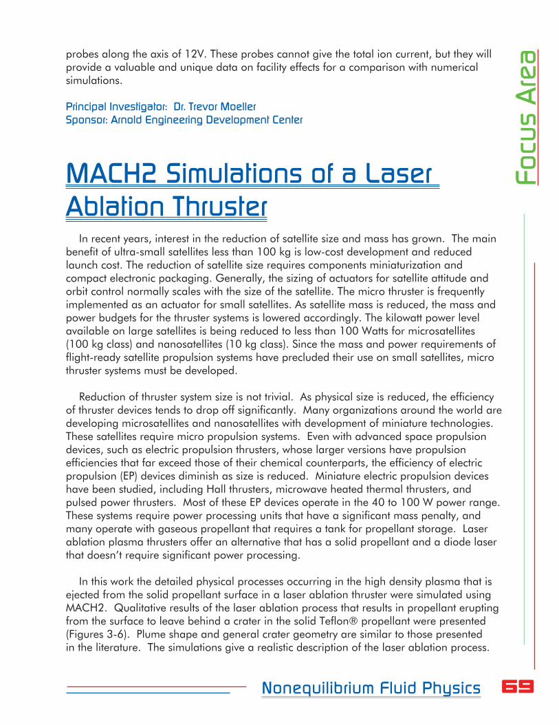
69Nonequilibrium Fluid Physics
Focu
s A
reaprobes along the axis of 12V. These probes cannot give the total ion current, but they will
provide a valuable and unique data on facility effects for a comparison with numerical simulations.
Principal Investigator: Dr. Trevor MoellerSponsor: Arnold Engineering Development Center
MACH2 Simulations of a Laser Ablation Thruster
In recent years, interest in the reduction of satellite size and mass has grown. The main benefit of ultra-small satellites less than 100 kg is low-cost development and reduced launch cost. The reduction of satellite size requires components miniaturization and compact electronic packaging. Generally, the sizing of actuators for satellite attitude and orbit control normally scales with the size of the satellite. The micro thruster is frequently implemented as an actuator for small satellites. As satellite mass is reduced, the mass and power budgets for the thruster systems is lowered accordingly. The kilowatt power level available on large satellites is being reduced to less than 100 Watts for microsatellites (100 kg class) and nanosatellites (10 kg class). Since the mass and power requirements of flight-ready satellite propulsion systems have precluded their use on small satellites, micro thruster systems must be developed.
Reduction of thruster system size is not trivial. As physical size is reduced, the efficiency of thruster devices tends to drop off significantly. Many organizations around the world are developing microsatellites and nanosatellites with development of miniature technologies. These satellites require micro propulsion systems. Even with advanced space propulsion devices, such as electric propulsion thrusters, whose larger versions have propulsion efficiencies that far exceed those of their chemical counterparts, the efficiency of electric propulsion (EP) devices diminish as size is reduced. Miniature electric propulsion devices have been studied, including Hall thrusters, microwave heated thermal thrusters, and pulsed power thrusters. Most of these EP devices operate in the 40 to 100 W power range. These systems require power processing units that have a significant mass penalty, and many operate with gaseous propellant that requires a tank for propellant storage. Laser ablation plasma thrusters offer an alternative that has a solid propellant and a diode laser that doesn’t require significant power processing.
In this work the detailed physical processes occurring in the high density plasma that is ejected from the solid propellant surface in a laser ablation thruster were simulated using MACH2. Qualitative results of the laser ablation process that results in propellant erupting from the surface to leave behind a crater in the solid Teflon® propellant were presented (Figures 3-6). Plume shape and general crater geometry are similar to those presented in the literature. The simulations give a realistic description of the laser ablation process.
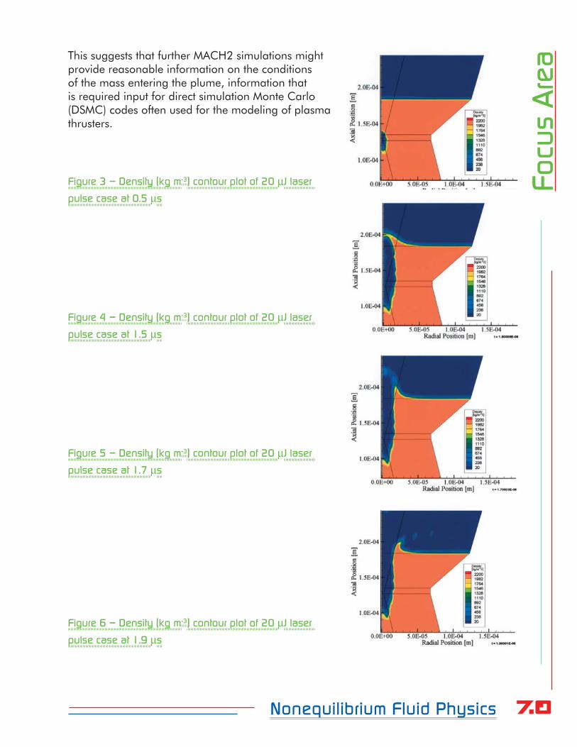
70Nonequilibrium Fluid Physics
Focu
s A
reaThis suggests that further MACH2 simulations might
provide reasonable information on the conditions of the mass entering the plume, information that is required input for direct simulation Monte Carlo (DSMC) codes often used for the modeling of plasma thrusters.
Figure 3 – Density (kg m-3) contour plot of 20 J laser
pulse case at 0.5 s
Figure 4 – Density (kg m-3) contour plot of 20 J laser
pulse case at 1.5 s
Figure 5 – Density (kg m-3) contour plot of 20 J laser
pulse case at 1.7 s
Figure 6 – Density (kg m-3) contour plot of 20 J laser
pulse case at 1.9 s
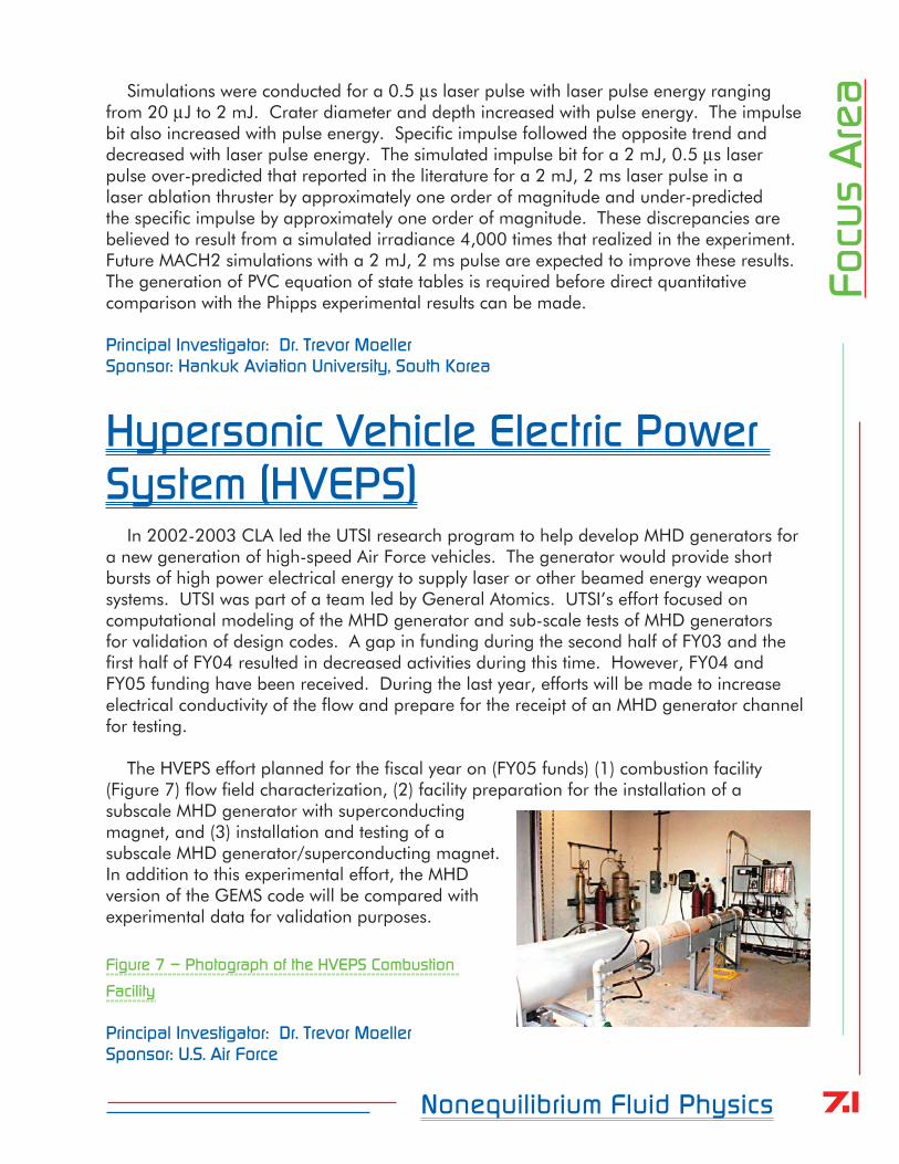
71Nonequilibrium Fluid Physics
Focu
s A
reaSimulations were conducted for a 0.5 s laser pulse with laser pulse energy ranging
from 20 J to 2 mJ. Crater diameter and depth increased with pulse energy. The impulse bit also increased with pulse energy. Specific impulse followed the opposite trend and decreased with laser pulse energy. The simulated impulse bit for a 2 mJ, 0.5 s laser pulse over-predicted that reported in the literature for a 2 mJ, 2 ms laser pulse in a laser ablation thruster by approximately one order of magnitude and under-predicted the specific impulse by approximately one order of magnitude. These discrepancies are believed to result from a simulated irradiance 4,000 times that realized in the experiment. Future MACH2 simulations with a 2 mJ, 2 ms pulse are expected to improve these results. The generation of PVC equation of state tables is required before direct quantitative comparison with the Phipps experimental results can be made.
Principal Investigator: Dr. Trevor MoellerSponsor: Hankuk Aviation University, South Korea
Hypersonic Vehicle Electric Power System (HVEPS)
In 2002-2003 CLA led the UTSI research program to help develop MHD generators for a new generation of high-speed Air Force vehicles. The generator would provide short bursts of high power electrical energy to supply laser or other beamed energy weapon systems. UTSI was part of a team led by General Atomics. UTSI’s effort focused on computational modeling of the MHD generator and sub-scale tests of MHD generators for validation of design codes. A gap in funding during the second half of FY03 and the first half of FY04 resulted in decreased activities during this time. However, FY04 and FY05 funding have been received. During the last year, efforts will be made to increase electrical conductivity of the flow and prepare for the receipt of an MHD generator channel for testing.
The HVEPS effort planned for the fiscal year on (FY05 funds) (1) combustion facility (Figure 7) flow field characterization, (2) facility preparation for the installation of a subscale MHD generator with superconducting magnet, and (3) installation and testing of a subscale MHD generator/superconducting magnet. In addition to this experimental effort, the MHD version of the GEMS code will be compared with experimental data for validation purposes.
Figure 7 – Photograph of the HVEPS Combustion
Facility
Principal Investigator: Dr. Trevor MoellerSponsor: U.S. Air Force

72
Focu
s A
reaFocus
Area
BiomedicalApplications
IntroductionThis area shows how the laser- and optical-physics background of the Center for Laser
Applications has been applied to the study of an extraordinarily complex system - the in vivo human eye. The theoretical and research endeavors outlined in this section include the development of analytical models of imperfect human eyes. These models are then used as the basis for the design and deployment of expert system-based diagnostics of large populations. We have implemented this system as a low-cost diagnostic that is compatible with telemedicine and has been used for eye screening in rural populations.
73Biomedical Applications
Focu
s A
rea
Optical Physics in CLAThe optical physics research of previous years in CLA has included the focus areas of
molecular spectroscopy, hyperfine particulate formation and diagnostics of jet engine combustors, and the characterization of local temperature and density properties of high temperature and dense plasmas. Analytical radiation models were developed to infer such local properties from ultraviolet-to-near infrared spectral measurements. The use of these models enabled systematic data reduction and Monte Carlo-based nonlinear error propagation techniques to be developed and successfully used. These capabilities were subsequently found to be useful in the study of the interaction of radiation with biological materials and specifically with the study of human eyes.
Beginning with the collaboration of UTSI/CLA and the UT Health Science Center (UTHSC), vision science research was begun in CLA and initially applied to the development of ocular telemedicine capabilities under a three-year Department of Commerce grant. The objective was achieved of developing the first autonomous telemedicine capability for large population pediatric screening measurements. Further, the clinical trial that was performed at the UTHSC demonstrated that: a) the modified commercially available screening instrument that was used was inadequate; b) accurate computational optical algorithms were required to simulate both population variances and simultaneous abnormalities of individuals; and most fundamental of all c) optical physics design is predictive and quantitative whereas medical diagnostics and treatment protocol is basically empirical.
These results have led, respectively, to a) the design and fabrication of a novel optical ocular diagnostics instrument, b) the development of both customized and improved statistically accurate eye models, and c) the capability of predicting performance and efficacy of optical ocular measurements. These developments are topics of the current research effort and offer significant application potential for autonomous ocular telemedicine, development of ocular instruments and treatment modalities, and computer-aided medical education and training.
A common theme of the applied vision science research of CLA is development of accurate predictions of both the performance and ophthalmic measurement results of human eyes. During the past few years, the CLA eye model has progressed through various versions toward detailed customized eye models. These personalized models are constructed with clinically measured data and derived biometrical parameters of individual patients so that model predictions match optical performance of the individuals. This pioneering personalized modeling can predict vision performance of individuals under specified viewing conditions and can assist in the prediction of the outcome of ocular surgery and treatments. As an example, this method is useful for the design and use of personalized intraocular lens, novel contact lens and ocular material evaluations. Finally, once validated, the CLA eye model and its ophthalmic simulation will yield a realistic simulation of ophthalmic measurements and will provide a powerful tool for medical training.

74Biomedical Applications
Focu
s A
rea
Figure 1– Customized eye modeling can assist the design of personalized contact lens,
spectacles, or intraocular lens
Biomedical Information Technology (BIT) Network
In collaboration with the UTHSC, UTSI/CLA is participating in the Biomedical Information Technology (BIT) Network project that is sponsored by the Army Telemedicine and Advanced Technology Research Center (TATRC). CLA will perform the theoretical and validation studies of a CLA-developed ocular screening algorithm for telemedicine applications. Specifically, we are developing a virtual optical eye bank that can be used as a generic tool to investigate the effectiveness of ocular screening instruments. The optical eye bank, a collection of personalized eye models, is constructed using real patients’ clinically measured data including the elevation maps, or topographies, of cornea surfaces; ultrasound biometry; and wavefront aberrations, which are the fingerprint of the eye’s optical performance. Using the model and these parameters, predictions and measurements will be compared of these patients using an independent ophthalmic measurement method.
The clinical data are being obtained through collaboration with Dr. Ming Wang of Wang Vision Institute in Nashville. Most of the models will be constructed using the existing database. Data will be obtained from a clinical trial that involves approximately one hundred patients. To perform this human clinical trial in Nashville and Tullahoma, an Institutional Review Board (IRB) application was submitted to UTK and tentatively approved in June and finally approved in August 3rd, 2006. The approval is valid for a study period of 12 months starting from the date of approval. The independent ophthalmic measurement will be obtained using the CLA- created instrument that is described in the subsequent section.
Ophthalmic Instrumentation A companion of our eye modeling research is the CLA development of novel
ophthalmic instrumentation that emphasizes the areas of applications: pediatric vision screening, keratoconus screening, and the cornea (dry eye and cornea scars) and optical

75Biomedical Applications
Focu
s A
reaopacity (cataract and floaters) diagnostics. In January 2006, a patent application, Adaptive
Photoscreening System (APS), was submitted by the principal investigators through UTRF. The multi-functional system can be utilized for both monocular measurements (APS-13) of the cornea and crystalline lens and for binocular measurements (APS-21) for pediatric vision screening. The instrument and its user friendly software program have been developed with the NASA Space Grant assistance for the past two years. The monocular system, APS-13, is also applied in the current clinical trial of the TATRC-sponsored BIT Network contract.
Figure 2 is an example of a near-infrared (NIR) monocular image data taken of a normal eye and represent both coaxial and eccentric images of the retinal reflex of multiple, sequenced NIR sources. The pupils were cropped from the raw image data by the software program and are presented in relative positions as eccentric illuminating conditions in the hardware. The photo on the left lower corner is an example of the raw data. In contrast, Figure 3 shows two images (raw data for visualization) of abnormal conditions resulting from dry eye and tear-film deficiency that are caused by contact lens wear. The observation of the tear film deficiency and dry eye syndrome is interesting in that it appears to offer an improved method for diagnostics of this condition. Further, the tear film itself is known to be comprised of three distinct liquid film layers whose total
estimated thickness of 4 micrometers is still controversial. The detection sensitivity of APS-13 on corneal surface variation is in the sub-micrometer range and is sufficient for observing tear film deficiency and cornea scars.
Figure 2 – APS images of a normal healthy
eye. The position of reflex corresponds to
the infrared illumination eccentricity in the
APS system
Figure 3 – Raw (unprocessed) APS-13 images of dry eye and tear film deficiency due to the
contact lens ware

76Biomedical Applications
Focu
s A
reaOphthalmic Simulation and Keratoconus Research
The objectives of this simulation effort are to provide assistance for medical training
and simulated performance measures for the development of instruments without the need for testing on real humans. As the CLA eye modeling technique has become more sophisticated, the simulation results in the past year mirror the ophthalmic measurements with increasing fidelity. The simulation of a common ophthalmic device, the streak retinoscope, was performed with the use of customized eye models. Currently, the retinoscopic observation of abnormalities by an ophthalmologist or optometrist can only be illustrated with hand drawn pictures or described in words. Shown in Figure 4 is one of the CLA retinoscopic simulation results from a customized keratoconus eye. The realistic luminance distribution on the patient pupil plane is presented and the famous keratoconus reflex is clearly shown.
Figure 4 – Computer simulation of retinoscopic observation of keratoconus eye using customized
eye model
The final and most exciting simulation is performed for CLA APS-13 system and provides initial validation of our eye model for myopic and keratoconus abnormalities. The simulation of the keratoconus (KC) eye is extremely challenging in that the abnormal eye is not cylindrically symmetric and the abnormality is characterized by corneal structures that have both physical height and width. On the right of Fig. 5 are the clinical measured (upper) and reconstructed (lower, in the computer model) corneal surface topographies. The cornea is 10 mm diameter and the pupil (as indicated in black dashed circle in the topography) is 6.1 mm diameter. The color bar represents the height of the topography from the reference sphere in micrometer. Using these clinical data, computations of the simulated performance of the APS-13 were obtained. For validation, the APS-13 images of this keratoconus patient were acquired experimentally, and the result is shown in Figure 6. Notice the red dashed circles in both Figures 5 and 6 indicate the knife-edge eccentric locations. The four corresponding images in Figure 5 and 6 are nearly identical. The validation is also performed for a myopic patient and the result also shows the agreement. These results are the first indication that large population KC screening may be possible with instruments as inexpensive as the APS-13.
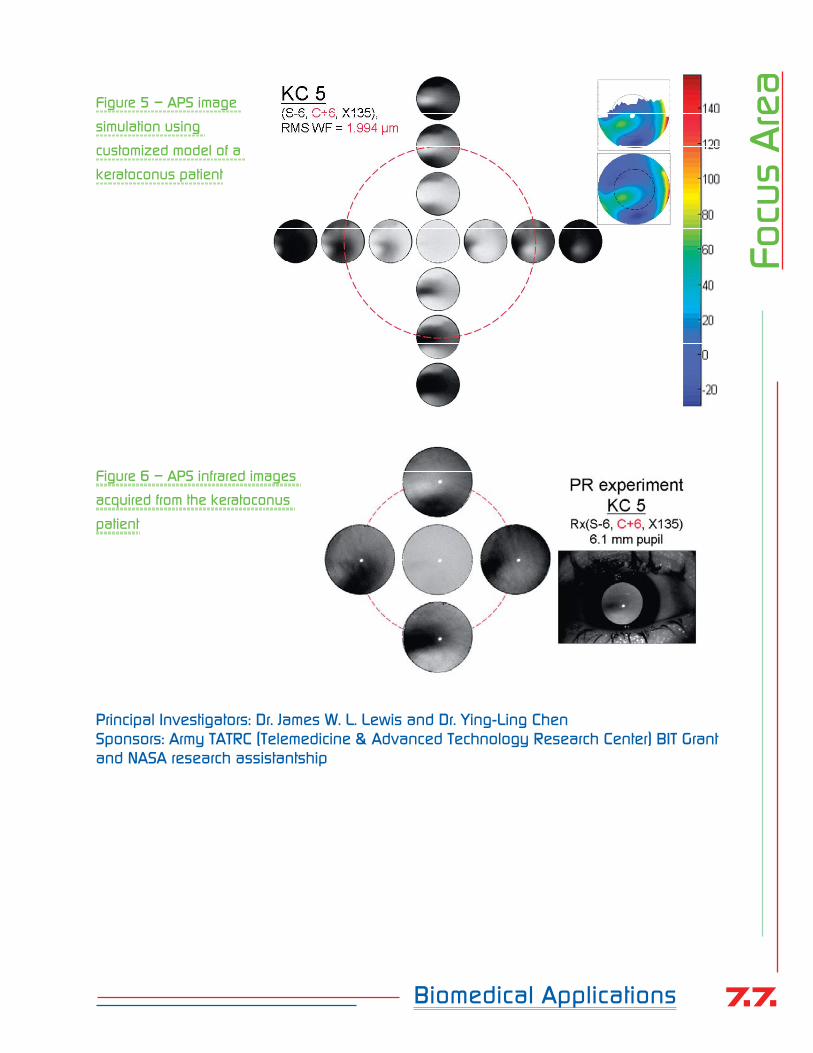
77Biomedical Applications
Focu
s A
rea
Figure 5 – APS image
simulation using
customized model of a
keratoconus patient
Figure 6 – APS infrared images
acquired from the keratoconus
patient
Principal Investigators: Dr. James W. L. Lewis and Dr. Ying-Ling ChenSponsors: Army TATRC (Telemedicine & Advanced Technology Research Center) BIT Grant and NASA research assistantship

78
Enric
hm
ent P
rogra
ms
EnrichmentProgramsCoffee County Middle School Demonstration
A total of 150 sixth, seventh and eighth graders from the Coffee County Middle School honor program visited the institute in three separate groups on different days and attended presentations on light and lasers and nanomaterials. Jim Wright, an Army helicopter pilot and graduate student in Aviation Systems, gave presentations on aeronautics and the physics of flight. Professor Hofmeister, Director of the Center for Laser Applications, explained physical concepts associated with light and lasers, and demonstrated “total internal reflection” which is the principle behind fiber optic communications. During their visit the students were encouraged to apply themselves while in middle school, especially in the math and science areas. The presentations were followed by lunch and a tour of AEDC.
Science ExposeCLA hosted two days of 2-4 hour mini-
courses on subjects ranging from math and computers to rockets and space for 44 Coffee County Central High School students. Aerodynamics, optics, lasers, plasma, and airplanes were among other topics covered in the sessions taught by UTSI faculty members. The courses
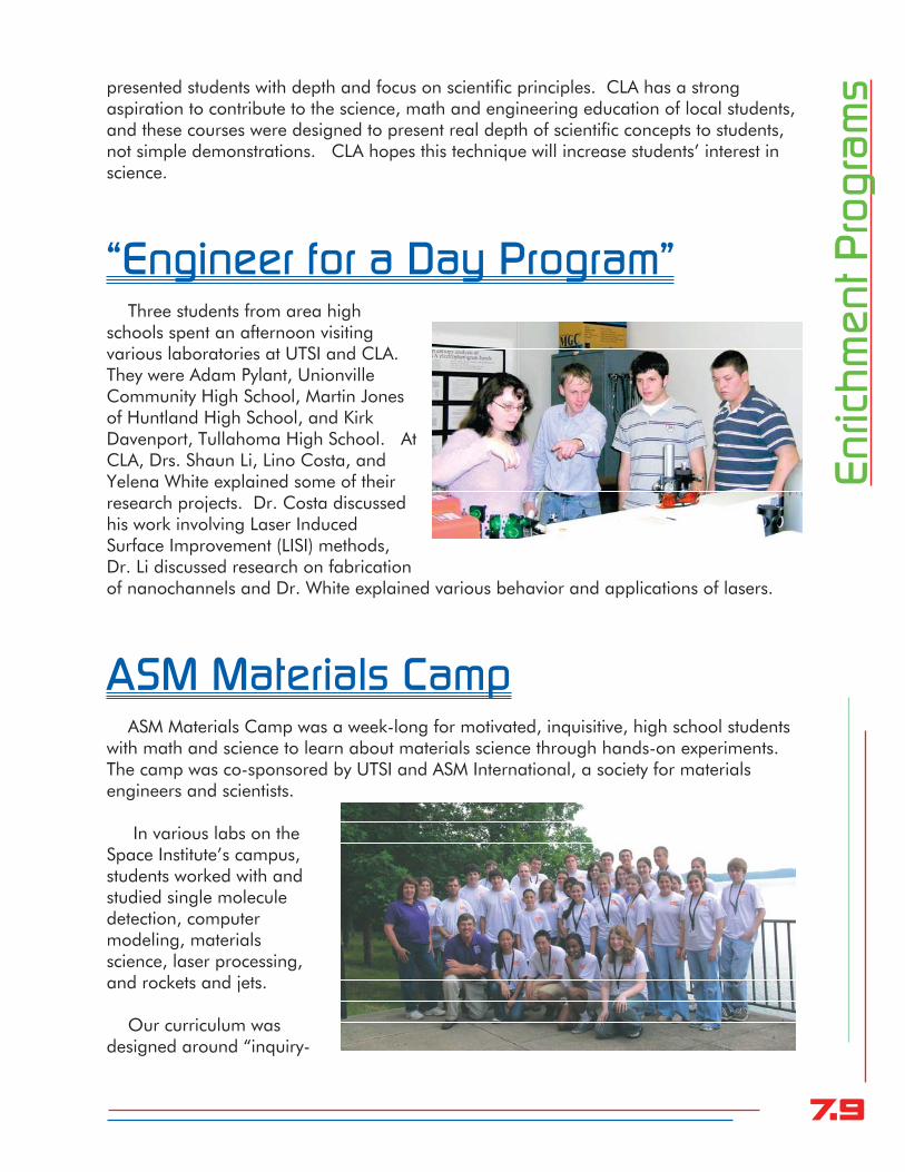
79
presented students with depth and focus on scientific principles. CLA has a strong aspiration to contribute to the science, math and engineering education of local students, and these courses were designed to present real depth of scientific concepts to students, not simple demonstrations. CLA hopes this technique will increase students’ interest in science.
“Engineer for a Day Program”Three students from area high
schools spent an afternoon visiting various laboratories at UTSI and CLA. They were Adam Pylant, Unionville Community High School, Martin Jones of Huntland High School, and Kirk Davenport, Tullahoma High School. At CLA, Drs. Shaun Li, Lino Costa, and Yelena White explained some of their research projects. Dr. Costa discussed his work involving Laser Induced Surface Improvement (LISI) methods, Dr. Li discussed research on fabrication of nanochannels and Dr. White explained various behavior and applications of lasers.
ASM Materials CampASM Materials Camp was a week-long for motivated, inquisitive, high school students
with math and science to learn about materials science through hands-on experiments. The camp was co-sponsored by UTSI and ASM International, a society for materials engineers and scientists.
In various labs on the Space Institute’s campus, students worked with and studied single molecule detection, computer modeling, materials science, laser processing, and rockets and jets.
Our curriculum was designed around “inquiry-
Enric
hm
ent P
rogra
ms

80
based understanding,” and some activities were truly innovative. The staff worked hard to create these activities and to minimize traditional “lecture” teaching. For example, the Mars Survivor Experiment challenged students to understand how to get liquid water on the polar ice cap of Mars! Mars’ pressure is below the triple point of water so water does not naturally exist at any temperature in the liquid phase. We designed a vacuum chamber with a water container and a heater/cooler, and guided the students through observation of the phases as a function of temperature and pressure. Through this activity we “discovered” the pressure-temperature phase diagram of water and correctly found they would need a pressure cooker to make water liquid on Mars.
Mad Science CampFifty-three 10-11 year old “motivated
and inquisitive learners” from area schools spent a week at The University of Tennessee Space Institute exploring many aspects of science.
The campers built an electric car, another they experimented with dry ice and turned a nickel into a penny using electroplating, constructed a DNA kit and took fingerprints and footprints to solve a crime scene mystery. Other activities included making their own cotton candy, causing their voices to
sound like robots, using deflection glasses to see a rainbow, making bouncing balls, and shooting rockets. The Mad Science franchise http://www.madscience.org/ focuses on science enrichment for children and has a well developed curriculum of discovery activities that are exciting, informative, and age appropriate. Keith Trehy of Nashville facilitated the camp, and was assisted by UTSI summer interns.
UTSI/CLA Shodor Scholars ProgramFifteen area high-school students and three Franklin County teachers attended a two-
week computational science session. The workshop was taught by Bob Gotwals from the Shodor Center for Computational Science Education in Durham, N.C. http://www.shodor.org Computational science is the area of scientific research that merges science, mathematics, and computing to produce computer models and simulations that allow users to study complex and challenging scientific behavior.
In the workshop, students were taught how to use models, modify existing models, and how to create models from scratch. Topics that were studied included computational
Enric
hm
ent P
rogra
ms

81
astrophysics, meteorology, agriculture, genomics, epidemiology, pharmacokinetics, and drug design and quantum chemistry. Students had an opportunity to write their own computer programs, using languages such as gnuplot, perl, and NetLogo. All the materials used in the class are available at no cost to students and teachers. Students developed a small computational research project of their own choosing and were given an opportunity to make presentations to an assembled group of proud parents at the end of the workshop. The teachers involved in the workshop learned how to deliver these materials in their own classrooms. This collaboration with Shodor is a continuing activity and will spread with the involvement of these dedicated teachers.
Science Fairs
CLA provided cash awards for two first place awards at the Fifty-Fourth Middle Tennessee Science and Engineering Fair. Drs. Hofmeister, Costa, White, and Li were judges at the fair held in Clarksville, TN.
Two students with local ties attended the Intel International Science Fair in Indianapolis. Kurt Davenport of Tullahoma High and Lucas Hofmeister of Martin Luther King Jr. Magnet School in Nashville.
Carole Thomas was a judge for the Sewanee Elementary Science Fair.
Dr. Pavlina Pike and Dr. Yelena White were the Science Fair Judges for Coffee County Middle School in early spring.
Enric
hm
ent P
rogra
ms

82
Outre
ach
to B
usi
nessOutreach to
BusinessFischer USAStainless Steel Tubing ManufacturerManchester, TN
Fischer USA http://www.fischer-usa.com/ is a manufacturer of welded stainless steel tubing located in Manchester, Tennessee. Starting in March of 2006 Professor Hofmeister delivered a series of three lectures (2 hours each) to six Fischer employees. These lectures were given with the help of two postdoctoral fellows at UTSI, Drs. Shaun Li and Yelena White. The curriculum covered basic materials science, the structure of metals, deformation mechanisms, hydro-forming, and laser-matter interactions specifically laser welding. In the course of this instruction, the students and faculty focused on a particular production problem, the fabrication of stainless tubing used in hydro-forming operations. As the staff at Fischer learned more of the basic science behind the operations, they were able to better understand the factors that influence tubing ductility. The lectures then morphed into “hands-on” failure analysis and instruction at UTSI in the summer to analyze the results of process variations on the mechanical properties of the material. This activity was of great benefit to Fischer-group and will help open more opportunities for the uses of their stainless steel products.
ATI Metalworking ProductsManufacturer and Supplier of Tungsten Alloys and Cutting ToolsLa Vergne, TN and Huntsville, AL
Allegheny Technologies has three business units in our area; ATI Stellram, a cutting tools group, ATI Alldyne, a tungsten-based alloy powder metal producer, and ATI Firth Sterling, a parts producer. We have investigated laser fabrication of tungsten carbide parts from powders supplied by Alldyne.

83
Vis
itors
to th
e L
abora
toryVisitors to the
Laboratory FY 05-06U.S. Congressman Harold Ford Jr.U.S. Congressman Lincoln Davis
AEDC Brig. Gen. Stringer, Commander of AEDCJoe Wheymeyer, ATA, AEDC
Dr. Nayer Eradat, Assistant Professor Physics and AstronomyMiddle Tennessee State University
Dr. Norman Tolk, Physics DepartmentVanderbilt University
Dr. David Millhorn, Vice President-ResearchHans A. DeSmidt, Assistant Professor, MABEUniversity of Tennessee
Dr. Shinath Vishawawan, Associate Professor, MS&EUniversity of Alabama
Dr. Claus Daniel, Wigner Fellow Oak Ridge National Laboratory
Dr. Jim Wittig, Professor MSEDirector, Interdisciplinary Graduate Program in Material ScienceVanderbilt University
Bill ZechmanHost for Manchester Exchange Club
Dr. WayKuoUT Knoxville, UT COE

84
Vis
itors
to th
e L
abora
toryKevin Holmes and Paul McElfresh
Innovative Technology, Baker Oil Tools
Wolfgang Roeder, Fischer GroupJay Vincent, Fischer GroupEric Elwell, Fischer Group
Tom Hall and Garth FrazierRadiance, Inc., Oxford, MS
Lane Donoho Bridget RodgesVanderbit University
Pedro Bastias, Dana Corporation
AEDC Summer Interns, Colleges, Major and Level of EducationNathan Campbell, TTU, ME, SrMichael Adam, Carter, TTU, Civil E, SrHarry Cooper, TTU, EE, SrCaitlin DuBois, TTU, EE, SrHolly Gallagher, TTU, ME, JrRichard Hopkins, TSU, EE, SrRick Hutchings, Purdue, AE, SrVanessa Kasten, TTU, IE, JrJerome King, MTSU, Cmp Info Sys, SrAnthony Nelson, UTK, AE, JrCarrie Reinholtz, Vandy, MSME, GradJamie Roetman, Embry Riddle, AE, SrAubrey Scott, University of Washington, Physics, JrZachary Sorensen, Auburn, AE, SrMichael Swift, Mercer, CmpE, SrGreg Tolley, UTK, CS, Sr
Jerry Washington, TSU, EE, SrValerie Webb, TSU, EE, SrMary Wetzel, MTSU, CmpSci, SrKyle B. Winkleman, TTU, Physics, SophDavid Yoder, TTU, ME, Sr Tennessee Technology Summer High School Emerging Technologies ProgramMr. Ken Hunter and 15 summer students

85
Vis
itors
to th
e L
abora
toryArea School Superintendents
Dan Lawson - Tullahoma SuperintendentCharles Edmonds - Franklin County SuperintendentDaniel Brigman – Coffee County SuperintendentJerry Hale, Warren County Superintendent Bobby Cox, Warren County, Director of Instruction Nancy Graham, Franklin Co. Elementary SupervisorDebbie Smith, Franklin Co. Secondary Supervisor
UT Chattanooga Student Government AssociationAmy Prevost William StaleyTiffany Hager Mark OllesReginald Smith, II Sean FischbachKristopher Davis Kevin BakerRegina Wilkerson Dan LehmanClaire Cripps Eric JacobEric Fox Matt DuranFaith Hollis David BallCacey Lewis Curtis SanderferRon Hodges Lauren Jaffries
Martin Engineering Students Visit UTSIThirteen engineering students from the University of Tennessee at Martin were given a tour of the research facilities and an opportunity to consider UTSI as a graduate school.
Coffee County Leadership GroupKelvin Shores, Coffee County Board of Education Niles Reddick, Motlow Community CollegeBrie Gentry, Coffee County RealtyRoger Buster, The Bank of TullahomaAndy Roake, AEDC Public AffairsBilly Philphott, Coffee County RealtyRenea Cotham, Wachovia SecuritiesChristy Glenn, Motlow Community CollegeFran Gray, Hospice of the Highland RimTim W. Keller, Good SamaritanDwayne Blanluk, Harton Regional Medical Center

86
Carla Bloom, Sportmen and BusinessmenMike Niederhauser, Mike Niederhauser’s/Vision Bank
Georgia Career Institute, McMinnville, TNCarolyn Kiber, Director Students: Angelica StoneGrace RogersJosh OsmentJennifer DunnRebecca CuevasSherrie MottKayla MearsAdara HardenRenee FannKayla CampbellGlenda SolomonGrant BarnesNatasha RamseyApril SkilesKirby BroomNancy GuzmanCindy MurphyMichelle BrewerIndia WareAmy ScottWhitney Miller
Vis
itors
to th
e L
abora
tory

87
Gra
nts
and C
ontra
cts
Awarded Grants and Contracts
Grants and Contracts in Fiscal Year 2004-2005
R02-4007010 - $1,021,874 expended in FY 2006 leaving $37,466 carryover to FY 2007“The Center for Laser Applications”State Appropriations, Dr. William Hofmeister, Director of CLAContract period: July 1, 2005 – June 30, 2006Total grant: $851,300 plus $208,040 carryover from previous yearsTotal grant available for FY 2006: $1,059,340
R02-4411021 - $3,643 expended in FY 2006“Joint Development of Superior Hardened Reliable Switch”Vanderbilt Microelectronics Group – Honeywell Kansas City– Dr. William HofmeisterContract period: October 1, 2005 – September 30, 2006Total award: $4,000
R02-4411022 - $4,643 expended in FY 2006“Direct Power Generation by Electron Emission from Carbon-Based Nanostructures”Vanderbilt Diamond Microelectronics Group – TVA – Dr. William HofmeisterContract period: October 1, 2006 – September 30, 2006Total award: $4,000
R02-4411023 - $6,927 expended in FY 2006“Advanced Carbon Nanotechnology Program”Vanderbilt Diamond Microelectronics Group – ARO – Dr. William HofmeisterContract period: October 1, 2006 – September 30, 2006Total award: $8,000

88
Gra
nts
and C
ontra
cts
R02-4313020 - $25,000 expended in FY 2006“CFDRC Air Force Phase I Research” CFD Research Facility – Dr. Ying-Ling ChenContract period: August 17, 2005- January 27, 2006Total award: $25,000
R02-4313021 - $0UT Memphis – Dr. Ying-Ling ChenArmy Grant W81XWH-0510409Contract period: March 1, 2006 – February 28, 2007Total award: $79,819
R02-4348022 - $158,487 expended in FY 2006Continuation to “Hypersonic Vehicle Electric Power System Technology Program”General Atomics, Dr. Trevor Moeller Contract period: April 2, 2005- April 3, 2007Total award: $751,299
“Small Center in Chemical Physics”UT Knoxville, Dr. L.M. Davis is a faculty collaboratorContract period: July 1, 2006- June 20, 2006Total award: $70,000
Continued Grants and Contracts in Fiscal Year 2005-2006
R02-4348020 - $460,080 expended in FY 2006“Hypersonic Vehicle Electric Power System Technology Program”General Atomics, Dr. Trevor Moeller Contract period: August 23, 2004- June 28, 2006 Total award: $953,480
R02-4348021 - $7,378 expended in FY 2006“Microthruster Project”Hankuk Aviation University, Dr. Trevor MoellerContract Period: February 2005-February 2007Total award: $10,000
R02-4325022 - $112,258 expended in FY 2006“Nuclear Fission Electrical Power and Propulsion”AEDC Task Order AF F 40600-00-D-0001/0024 , Dr. MoellerContract Period: February 2003 - April 2007Total Award $350,000

89
Gra
nts
and C
ontra
ctsR02-4318026 - $11,190 expended in FY 2006
“Capillary System for Fluorescence Fluctuation Spectroscopy Applications to Pharmaceutical Drug Discovery Research”Abbott Laboratories, Dr. L.M. Davis Contract period: November 2004 – November 2006Total award $33,000
R02-4318027 - $12,172 expended in FY 2006“Scanning Fluorescence Fluctuation Spectroscopy”Abbott Laboratories, Dr. L.M. DavisContract period: November 10, 2004 – November 9, 2006Total award: $24,600
R02-4318028 - $3,362 expended in FY 2006“Scanning Fluorescence Fluctuation Spectroscopy Data Acquisition”Abbott Laboratories, Dr. L.M. DavisContract period: November 11, 2004 – November 10, 2006Total award: $8,000
R02-4318029 - $40,170 expended in FY 2006“Maximum-likelihood Multi-channel Fluorescence Microscopy”National Institutes of Health grant 1R03EB004586-01A1, Dr. L.M. Davis Contract period: August 1, 2005 – July 31, 2007Total award: $150,300
R02-4331005 - $293,054 expended in FY 2006“LISI Phase I: Prototype Production Facility Development”AEDC, Dr. William Hofmeister Total award: $2,568,000Contract period: July 25, 2001 – September 30, 2006
R02-4317024 - $5,534 expended in FY 2006“High Speed Laser Synthesis of Amorphous Surface Structures”National Science Foundation: U.S. – India Cooperative ResearchContract period: April 15, 2004 – March 31, 2007Total award: $23,173
Total Research funds expended in FY 2006 = $2,165,772

90
Stu
dents
Students
Student Thesis/Dissertation
Karen Norton, MS, Physics, advisor: Dr. Lloyd Davis “Ultraviolet Image Analysis of Spacecraft Exhaust Plumes”
Graduate Students Planning to Graduate the Fall of 2006
Daniel Rooney, M.S. Engineering Science Dr. MoellerDavid Ball, M.S. Physics Dr. Davis
Graduate Students Enrolled in FY 2006
Sandip Harimkar, PhD Materials Science Dr. DahotreNikki Brown, M.S., Materials Science Dr. DahotreGreg Engleman, Ph.D. Materials Science Dr. DahotreIsaac Lescano-Mendoza, MS Electrical Engineering Dr. HofmeisterKevin Baker, M.S. Physics Dr. LewisBo Tan, M.S. Physics Dr. LewisAnil Kumar Kurella Materials Science Dr. DahotreSonya Nelsen, M.S. Engineering Science Dr. MoellerMatt Dackman, M.S. Physics Dr. MoellerLei Shi, M.S. Physics Dr. Chen
New Students Recruited for FY 2007
Anoop Samant, Ph.D. Materials Science Dr. Narendra DahotreJeffery King, MS Mechanical Engineering Dr. Trevor MoellerDeepak Rajput, MS Materials Science Dr. William HofmeisterJames Aiken, MS Physics Dr. Lloyd Davis Will Robinson, MS Physics Dr. Lloyd Davis

91
Post Doctoral Fellows Recruited in FY 2006
Dr. Jose Lino Vasconcelos da Costa Dr. Xiaoxuan Shaun Li Dr. Yelena Vladimrovna White Dr. Pavlina Pike - summer
Interns Employed for Summer 2006
Kirk DavenportNatasha GuptaGraham Hunter PeekAnastasia PetrovaPaul SherrouseHeather SteeleWilliam Vick
Stu
dents

92
Inte
rns
for Sum
mer 2
00
6
Interns for Summer 2006“Magnificent Seven,” Summer Interns for 2006
The summer interns of 2006, also known as the “magnificent seven,” worked with Dr. Hofmeister and his staff to gain hands on knowledge of the world of research and experimentation in a laboratory environment.
Pictured below are William Vick, Anastasia Petrova, Paul Sherrouse, Natasha Gupta, Hunter Peek, Heather Steele and Kirk Davenport.
William Vick is currently enrolled as a junior at Tennessee Tech studying mechanical engineering. He went to high school at Montgomery Bell Academy in Nashville and started his college level education at Auburn University. He transferred to Tennessee Tech in 2004. He plans to continue in the field of mechanical engineering and plans on becoming involved with the automotive industry.
Anastasia Olegovna Petrova is 16 and is a junior at Tullahoma High School. She was born in Uzbekistan, Tashkent and moved to United States in 2002. She speaks Russian and English fluently. She would like to be a radiologist.
Paul Sherrouse is a rising freshman transferring from Motlow Community College to Tennessee Tech this fall. He had a very exciting high school career since he was home schooled and was able to participate in lots of extracurricular activities such as 4-H,

93
debate, auto repair, and many other hobbies. His interests have been serving God, helping people and improving/creating/exploring things. He was able to do all these things as part of his summer job at UTSI which made it more like a hobby or vacation than a “job.” He is pursuing an education in mechanical engineering.
Natasha Gupta is a 2006 graduate of Tullahoma High School and is attending Duke University as a freshman this fall. She is majoring in biology, with a minor in philosophy, and plans to earn a certificate in global health policy. She has a keen interest in pursuing research opportunities while in academia and, therefore, was grateful for the summer experience with CLA. Her future plans include attending medical school and possibly earning a Ph.D. (in a fleld of interest that has yet to be determined).
Heather Steele is 19 years old and will be a sophomore this fall at MTSU in Murfreesboro. She plans to be a Pharmacist, which means she will be getting her Bachelor’s Degree in Biology with a minor in Chemistry, and will then go on to pharmacy school for four more years.
Hunter Peek graduated from Tullahoma High School in 2004. This fall he will be a junior at UTK where he is majoring in biomedical engineering. He is unsure about his career choice at this time but hopes that his experience this summer will help him decide on a career path.
Kirk Davenport graduated from Tullahoma High school in 2006 and received the opportunity to work at UTSI through the engineering for a day program at AEDC. During that program he spent the afternoon touring UTSI’s CLA facilities. He is very interested in engineering and will be majoring in mechanical engineering for his undergraduate degree at University of Utah. He hopes to someday become a research professor.
Inte
rns
for Sum
mer 2
00
6

94
Public
atio
ns
and P
rese
nta
tions
Publications andPresentationsPublications“Accounting for Triplet and Saturation Effects in FCS Measurements,” L.M. Davis and G. Shen, Current Pharmaceutical Biotechnology 7, 287-301, 2006. “Prediction of Solidification Microstructures During Laser Dessing of Alumina Grinding Wheel Material”, S. P. Harimkar, A. N. Samant, A. A. Khangar, and Narendra B. Dahotre, J. Physics-D: Applied Physics, Vol. 39, pp. 1642-1649, 2006. “Laser Surface Cladding of Fe-B-C, Fe-B-Si and Fe-BC-Si-Al-C on Plain Carbon Steel”, I. Manna, J. Dutta Majumdar, B. Ramesh Chandra, S. Nayak, and Narendra B. Dahotre, Surface and Coatings Technology, Vol. 201, pp. 434-440, 2006.
“Accounting for Triplet and Saturation Effect in FCS Measurements,” L.M. Daivs and G. Shen, Current Pharmaceutical Biotechnology 7, 287-301 (2006). “Fabrication of aligned convex CNT field emission triode by MPCVD,” Y.M. Wong, W.P. Kang, J.L. Davidson, B.K. Choi, W. Hofmeister and J.H. Huang; Diamond and Related Materials, February-March 2006, vol. 15, issues 2-3, pp. 334-340.
“Geometrical field enhancement on micropatterned nanodiamond film for electron emissions,” K. Subramanian, W.P. Kang, J.L. Davidson, J.D. Jarvis, W.H. Hofmeister, B.K. Choi and M. Howell; Diamond and Related Materials, February-March 2006, vol. 15, issues 2-3, pp. 417-425.
“Laser Induced Functionally Textured Bio-coating”, Anil Kurella and Narendra B. Dahotre, Journal of Minerals, Metals and Materials Society (JOM), Vol. 57, No. 7, pp. 64-66, 2006.
“Carbon nanostructure field emission devices,” Y.M. Wong, W.P. Kang, J.L. Davidson, K.L. Soh, B.K. Choi, and W.H. Hofmeister, Journal of Vacuum Science and Technology B, March-April 2006, vol. 24, issue 2, pp. 1008-1012.

95
Public
atio
ns
and P
rese
nta
tions
“Diamond and carbon-derived vacuum micro- and nano-electronic devices,” W.P. Kang, J.L. Davidson, A. Wisitsora-at, Y.M. Wong, R. Takalkar, K. Subramania, D.V. Kerns and W.H. Hofmeister; Diamond and Related Materials, March-July 2005, vol. 14, issues 3-7, pp. 685-691.
“The effect of growth rate control on the morphology of nanocrystalline diamond,” K. Subramanian, W.P. Kang, J.L. Davidson and W.H. Hofmeister; Diamond and Related Materials, March-July 2005, vol. 14, issues 3-7, pp. 404-410. “Nanodiamond planar lateral field emission diode,” K. Subramanian, W.P. Kang, J.L. Davidson, W.H. Hofmeister, B.K. Choi and M. Howell; Diamond and Related Materials, November-December 2005, vol. 14, issues 11-12, pp. 2099-2104. “Field emission triode amplifier utilizing aligned carbon nanotubes,” Y.M. Wong, W.P. Kang, J.L. Davidson, B.K. Choi, W. Hofmeister and J.H. Huang; Diamond and Related Materials, November-December 2005, vol. 14, issues 11-12, pp. 2069-2073.
“Array geometry, size and spacing effects on field emission characteristics of aligned carbon nanotubes,” Y.M. Wong, W.P. Kang, J.L. Davidson, B.K. Choi, W. Hofmeister and J.H. Huang; Diamond and Related Materials, November-December 2005, vol. 14, issues 11-12, pp. 2078-2083.
“Device characterization of carbon nanotubes field emitters in diode and triode configurations,” Y.M. Wong, W.P. Kang, J.L. Davidson, W. Hofmeister, S. Wei and J.H. Huang; Diamond and Related Materials, March-July 2005, vol. 14, issues 3-7, pp. 697-703.
“Field emission characteristics of diamond edge-shaped emitters fabricated using nitrogen-methane plasma,” R.S. Takalkar, W.P. Kang, J.L. Davidson, B.K. Choi, W.H. Hofmeister and K. Subramanian, Diamond and Related Materials, February-March 2006, vol. 15, issues 2-3, pp. 329-333.
“Laser-induced carbon plasma emission spectroscopic measurements on solid targets and in gas-phase optical breakdown,” László Nemes, Anna M. Keszler, James O. Hornkohl, and Christian G. Parigger, Applied Optics, Vol. 44, Issue 18, pp. 3661-3667, 2005.
“Diatomic Hönl-London factor computer program,” James O. Hornkohl, Christian G. Parigger, and László Nemes, Applied Optics, Vol. 44, Issue 18, pp. 3686-369, 2005.
“Synthesis of Platinum-Loaded Zirconia on Fecralloy Using Composite Plasma-Polymerized Films.” P.D. Pedrow, R. Dhar, T.M. Moeller, Q. Ming, K.C. Lidell, and M.A. Osman, IEEE Transactions on Plasma Science, Volume 33, Issue 6, Part 2, Dec. 2005 Page(s):2035 – 2045.
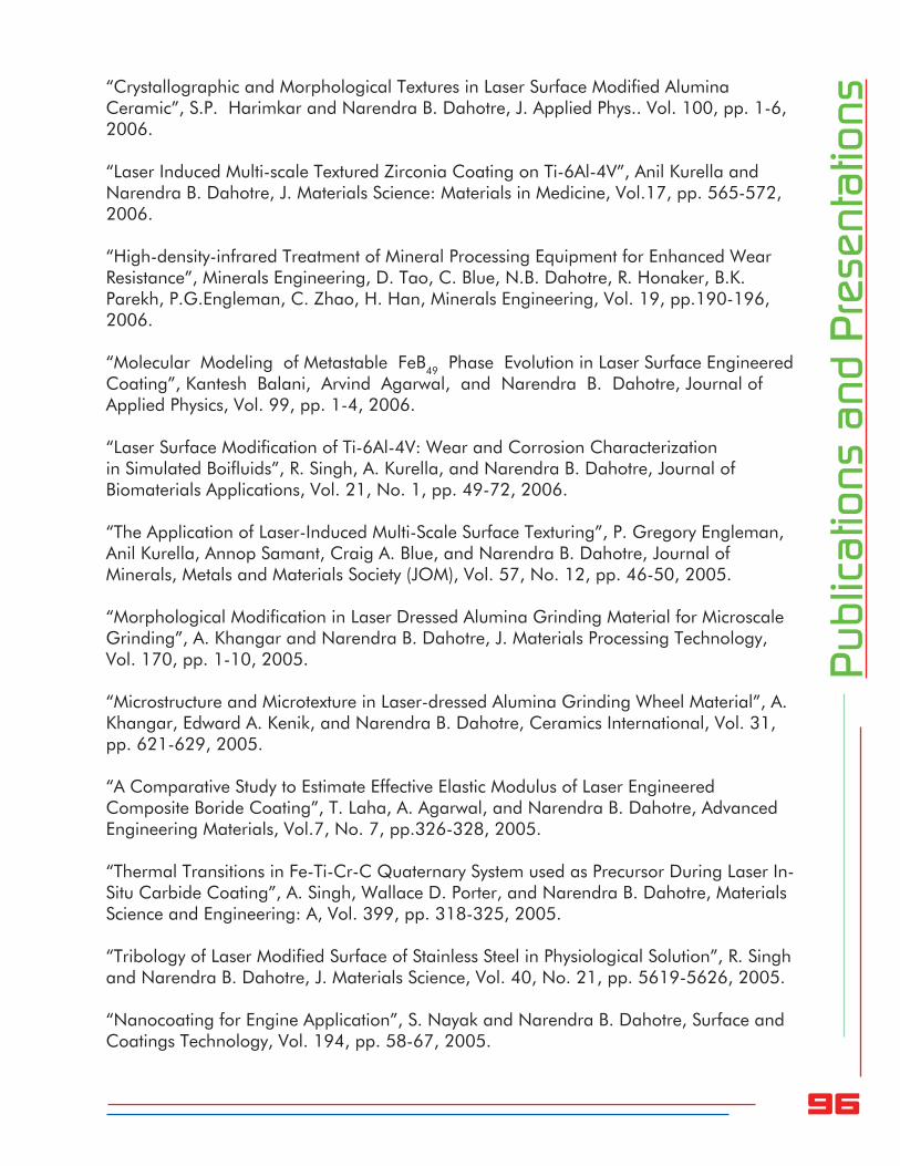
96
Public
atio
ns
and P
rese
nta
tions“Crystallographic and Morphological Textures in Laser Surface Modified Alumina
Ceramic”, S.P. Harimkar and Narendra B. Dahotre, J. Applied Phys.. Vol. 100, pp. 1-6, 2006.
“Laser Induced Multi-scale Textured Zirconia Coating on Ti-6Al-4V”, Anil Kurella and Narendra B. Dahotre, J. Materials Science: Materials in Medicine, Vol.17, pp. 565-572, 2006.
“High-density-infrared Treatment of Mineral Processing Equipment for Enhanced Wear Resistance”, Minerals Engineering, D. Tao, C. Blue, N.B. Dahotre, R. Honaker, B.K. Parekh, P.G.Engleman, C. Zhao, H. Han, Minerals Engineering, Vol. 19, pp.190-196, 2006.
“Molecular Modeling of Metastable FeB49 Phase Evolution in Laser Surface Engineered Coating”, Kantesh Balani, Arvind Agarwal, and Narendra B. Dahotre, Journal of Applied Physics, Vol. 99, pp. 1-4, 2006.
“Laser Surface Modification of Ti-6Al-4V: Wear and Corrosion Characterization in Simulated Boifluids”, R. Singh, A. Kurella, and Narendra B. Dahotre, Journal of Biomaterials Applications, Vol. 21, No. 1, pp. 49-72, 2006.
“The Application of Laser-Induced Multi-Scale Surface Texturing”, P. Gregory Engleman, Anil Kurella, Annop Samant, Craig A. Blue, and Narendra B. Dahotre, Journal of Minerals, Metals and Materials Society (JOM), Vol. 57, No. 12, pp. 46-50, 2005.
“Morphological Modification in Laser Dressed Alumina Grinding Material for Microscale Grinding”, A. Khangar and Narendra B. Dahotre, J. Materials Processing Technology, Vol. 170, pp. 1-10, 2005.
“Microstructure and Microtexture in Laser-dressed Alumina Grinding Wheel Material”, A. Khangar, Edward A. Kenik, and Narendra B. Dahotre, Ceramics International, Vol. 31, pp. 621-629, 2005.
“A Comparative Study to Estimate Effective Elastic Modulus of Laser Engineered Composite Boride Coating”, T. Laha, A. Agarwal, and Narendra B. Dahotre, Advanced Engineering Materials, Vol.7, No. 7, pp.326-328, 2005.
“Thermal Transitions in Fe-Ti-Cr-C Quaternary System used as Precursor During Laser In-Situ Carbide Coating”, A. Singh, Wallace D. Porter, and Narendra B. Dahotre, Materials Science and Engineering: A, Vol. 399, pp. 318-325, 2005.
“Tribology of Laser Modified Surface of Stainless Steel in Physiological Solution”, R. Singh and Narendra B. Dahotre, J. Materials Science, Vol. 40, No. 21, pp. 5619-5626, 2005.
“Nanocoating for Engine Application”, S. Nayak and Narendra B. Dahotre, Surface and Coatings Technology, Vol. 194, pp. 58-67, 2005.

97
Public
atio
ns
and P
rese
nta
tions
“Surface Modification for Bioimplants: The Role of Laser Surface Engineering”, Anil Kurella and Narendra B. Dahotre, Journal of Biomedical Applications, Vol. 20, No. 1, pp. 5-50, 2005.
“Keratoconus Screening Instrumentation”, K.C. Baker, Y.–L. Chen, B. Tan, J.W. L. Lewis, L. Shi, Y. Jiang, and M. Wang, Invest. Ophthalmol. Vis. Sci. 2006 47: 4050.
“Visualization Of Ophthalmic Measurement Using Computer Eye Modeling”, B. Tan, Y.–L. Chen, K. Baker, J.W. L. Lewis, L. Shi, Y. Jiang, and M. Wang, Invest. Ophthalmol. Vis. Sci. 2006 47: 1169.
“Digital Eye Bank”, Y.–L. Chen, J.W. L. Lewis, B. Tan, K. Baker, M. Wang, and L. Shi, Invest. Ophthalmol. Vis. Sci. 2006 47, 1188.
“Computer Real-Time Analysis in Mobile Ocular Screening”, Ying-ling Chen, J. W. L. Lewis, Natalie Kerr, and Ross Kennedy, Telemedicine and e-Health Journal, vol. 12, no 1, 2006. http://www.liebertonline.com/doi/abs/10.1089/tmj.2006.12.66
“Time-resolved temperature images of laser-ignition using OH two-line laser-induced fluorescence (LIF) thermometry”, Wenhong Qin, Ying-Ling Chen, and J. W. L. Lewis , The IFRF Electronic Combustion Journal, Article Number 200508, November 2005 http://www.journal.ifrf.net/200508chen.html.
Presentations and Proceedings“The C3 Puzzle: Formation of and Spontaneous Emission from the C3 Radical in Carbon Plasma,” László Nemes, Anna M. Keszler, Christian G. Parigger, James O. Hornkohl, Hope A. Michelsen, and Vadim Stakhursky, Internet Electronic Journal of Molecular Design, March 2006, Volume 5, Number 3, Pages 150–167, Proceedings of the International Symposium on Carbon Materials – Theoretical and Experimental Aspects, Budapest, October 24–26, 2005. “On Measurements of Laser-Induced Plasma,” Christian G. Parigger, in Proceedings of the 18-th International Conference on Spectroscopic Line Shapes (ICSLS, Auburn, AL), 2006. “Measurements of Aluminium Laser-Induced Breakdown Spectra,” James O. Hornkohl, Christian G. Parigger, László Nemes, and Anna M. Keszler, in Laser Applications to Chemical, Security and Environmental Analysis 2006 Technical Digest (The Optical Society of America, Washington, DC), TuE4, 2006.
“On the 400-nm continuum in spectra of laser ablation graphite plasma,” László Nemes, Anna M. Keszler, James O. Hornkohl and Christian G. Parigger, in Laser Applications to Chemical, Security and Environmental Analysis 2006 Technical Digest (The Optical Society of America, Washington, DC), TuE8, 2006.

98
Public
atio
ns
and P
rese
nta
tions
“Finite Element Analysis Of Laser Induced Surface Improvement Of Al Alloys With Tic,” Lino Costa, William Hofmeister, Narendra Dahotre, Proceedings of the International PowderMet2006 Conference, San Diego, June 19-21, 2006. MPIF, X, X, 2006 Advanced in PM&PM Proceedings of the 2006 International Science, San Diego, CA (MPIF, Princeton, NJ, 2006).
“Evolving High-Performance Evolutionary Computations for Space Vehicle Design,” Gerry Dozier, Win Britt, Michael SanSoucie, Patrick Hull, Michael Tinker, Ron Unger, Steve Bancroft, Trevor Moeller and Dan Rooney, IEEE World Congress on Computational Intelligence, Vancouver, B.C., Canada, July 16-21, 2006.
“Experimental ad Computer Simulation Studies of a Pulsed Plasma Accelerator,” T. Moeller, R. Rhodes, D. Keefer, C. Merkle and D. Li, The 33rd IEEE International Conference on Plasma Science, Traverse City, Michigan, June 4-8, 2006.
“Comparison of Experimental and Computational Simulations Results of a Pulsed Plasma Accelerator,” T. Moeller, D. Keefer, R. Rhodes, D. Rooney, D. Li, and C. Merkle, IEPC-2005-008, The 29th International Electric Propulsion Conference, Princeton University, October 31 – November 4, 2005.
“Appearance of keratoconus eyes: computation” Kevin Baker, Ying-Ling Chen, J.W.L. Lewis, and Ming Wang, OSA Vision Meeting, Tucson, AZ, Oct. 21, 2005.“Ammetropia: the Ocular Shape and Dimensions”, Bo Tan, Ying-Ling Chen, and J.W.L. Lewis, OSA Vision Meeting, Tucson, AZ, Oct. 21, 2005.
“Nanoscale Emitters and Single-Molecule Detection in Nanochannels,” W.H. Hofmeister, L.M. Davis, J. Davidson, W.P. Kang, D. Li and J.P. Wikswo, Nanomaterials for Defense Applications 2006, Virginia Beach, VA, May 1-4 , 2006.
“Time-Resolved Spectral Imaging at Low Signal Levels,” G. Shen and L.M. Davis, Biophysical Society annual meeting, February 18-22, 2006, Salt Lake City, UT; Biophysical Journal, Abstracts, 1414-pos (2006).
“Dynamic Properties of Photoluminescence from Porous Silicon,” K.H. Lee, K.S. Jeon, D.A. Ball, G. Shen, and L.M. Davis, 96th Annual Meeting of the Korean Chemical Society, Wonju, Korea, October 21-22, 2005.
“Multi-Channel Imaging Capabilities at Low Signal Levels,” L.M. Davis, and G. Shen, Frontiers in Optics/Laser Science, Optical Society of America, Tucson, AZ, October 16-20, 2005.

99
Public
atio
ns
and P
rese
nta
tionsBook Chapters
“Laser-Induced breakdown in gases: experiments and simulation,” in Laser-Induced Breakdown Spectroscopy edited by A. Miziolek, V.Palleschi, and I Schechter (Cambridge: Cambridge University Press, ISBN 0-521-85274-9), Chapter 4, pp 171-193, 2006.
Invited PresentationsLouisiana State University, Chemistry Dept., L.M. Davis, November, 2005.Middle State University, Physics Dept., L.M. Davis, March 30, 2006.
“On Measurements of Laser-Induced Plasma,” Christian G. Parigger, 18th International Conference on Spectroscopic Line Shapes, The University of Auburn, AL, June 2006.
Invited presentation, “Laser Surface Engineering”, by Narendra B. Dahotre at the National Metallurgical Laboratory, Jamshedpur, India, December, 9, 2005.

100
Futu
re D
irect
ions
Future Directions for the Center for Laser Applications
The future directions of the Center for Laser Applications must be aligned with the goals of the University. A clear statement of the goals of the University of Tennessee and the State of Tennessee for the University of Tennessee Space Institute can be found in the revised plan for UTSI submitted to the state legislature [1]. The first two recommendations are as follows:
1. The UTSI research program should focus on mission-oriented applied research and development in two areas: materials science, including laser applications, and aerospace science, including propulsion.
2. UTSI should develop innovative interdisciplinary Doctoral programs in materials science engineering and aerospace engineering.
In September of 2005, UTSI hired Professor William Hofmeister, Research Professor of Materials Science and Engineering, as Director of the Center for Laser Applications, a Tennessee Higher Education Commission Center of Excellence, to further develop the Materials Science program at UTSI. The report also stated that this research and education effort should be “closely linked with efforts at regional centers and universities such as Arnold Engineering and Development Center, Oak Ridge National Laboratory, NASA Marshall Space Flight Center, UT Knoxville, UT Chattanooga, Tennessee Tech, and Vanderbilt University.” Given the stated directions of the legislature and the UT administration, the strong national emphasis on nanotechnology and the investment of the Department of Energy in ORNL’s Center for Nanomaterials Science (CNMS), it is natural that UTSI and CLA pursue collaborations in areas of current strength: single-molecule detection and photonic processing of materials.
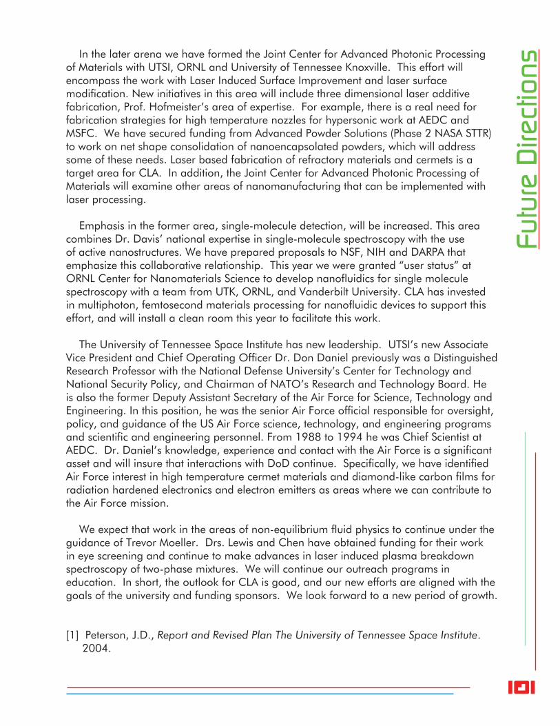
101
Futu
re D
irect
ions In the later arena we have formed the Joint Center for Advanced Photonic Processing
of Materials with UTSI, ORNL and University of Tennessee Knoxville. This effort will encompass the work with Laser Induced Surface Improvement and laser surface modification. New initiatives in this area will include three dimensional laser additive fabrication, Prof. Hofmeister’s area of expertise. For example, there is a real need for fabrication strategies for high temperature nozzles for hypersonic work at AEDC and MSFC. We have secured funding from Advanced Powder Solutions (Phase 2 NASA STTR) to work on net shape consolidation of nanoencapsolated powders, which will address some of these needs. Laser based fabrication of refractory materials and cermets is a target area for CLA. In addition, the Joint Center for Advanced Photonic Processing of Materials will examine other areas of nanomanufacturing that can be implemented with laser processing.
Emphasis in the former area, single-molecule detection, will be increased. This area combines Dr. Davis’ national expertise in single-molecule spectroscopy with the use of active nanostructures. We have prepared proposals to NSF, NIH and DARPA that emphasize this collaborative relationship. This year we were granted “user status” at ORNL Center for Nanomaterials Science to develop nanofluidics for single molecule spectroscopy with a team from UTK, ORNL, and Vanderbilt University. CLA has invested in multiphoton, femtosecond materials processing for nanofluidic devices to support this effort, and will install a clean room this year to facilitate this work.
The University of Tennessee Space Institute has new leadership. UTSI’s new Associate Vice President and Chief Operating Officer Dr. Don Daniel previously was a Distinguished Research Professor with the National Defense University’s Center for Technology and National Security Policy, and Chairman of NATO’s Research and Technology Board. He is also the former Deputy Assistant Secretary of the Air Force for Science, Technology and Engineering. In this position, he was the senior Air Force official responsible for oversight, policy, and guidance of the US Air Force science, technology, and engineering programs and scientific and engineering personnel. From 1988 to 1994 he was Chief Scientist at AEDC. Dr. Daniel’s knowledge, experience and contact with the Air Force is a significant asset and will insure that interactions with DoD continue. Specifically, we have identified Air Force interest in high temperature cermet materials and diamond-like carbon films for radiation hardened electronics and electron emitters as areas where we can contribute to the Air Force mission.
We expect that work in the areas of non-equilibrium fluid physics to continue under the guidance of Trevor Moeller. Drs. Lewis and Chen have obtained funding for their work in eye screening and continue to make advances in laser induced plasma breakdown spectroscopy of two-phase mixtures. We will continue our outreach programs in education. In short, the outlook for CLA is good, and our new efforts are aligned with the goals of the university and funding sponsors. We look forward to a new period of growth.
[1] Peterson, J.D., Report and Revised Plan The University of Tennessee Space Institute. 2004.