Embed Size (px)
DESCRIPTION
Do and donts of using Center Rock down hole hammers
Citation preview

August 23, 2010

The Do’s & Don’ts of LP Drilling1) Before bolting on LP Drill, blow out any debris from the entire air system. From the outlet of the air compressors, through the manifold, air hoses, swivel, or any other drill string components. This is also a good time to adjust the oiler and double check that oil is being injected into air stream. Should see at least a mist of oil. NOTE: check this with a piece of wood, held into the the airstream. Do not put your hand into the airstream. (½ gal. / 1000 cfm. / drilling hour)
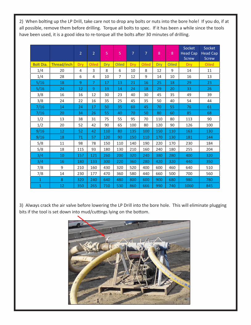
2) When bolting up the LP Drill, take care not to drop any bolts or nuts into the bore hole! If you do, if at all possible, remove them before drilling. Torque all bolts to spec. If it has been a while since the tools have been used, it is a good idea to re-torque all the bolts after 30 minutes of drilling.
3) Always crack the air valve before lowering the LP Drill into the bore hole. This will eliminate plugging bits if the tool is set down into mud/cuttings lying on the bottom.
2 2 5 5 7 7 8 8Socket
Head Cap Screw
Socket Head Cap
ScrewBolt Dia. Thread/inch Dry Oiled Dry Oiled Dry Oiled Dry Oiled Dry Oiled
1/4 20 4 3 8 6 10 8 12 9 14 111/4 28 6 4 10 7 12 9 14 10 16 13
5/16 18 9 7 17 13 21 16 25 18 29 235/16 24 12 9 19 14 24 18 29 20 33 263/8 16 16 12 30 23 40 30 45 35 49 393/8 24 22 16 35 25 45 35 50 40 54 44
7/16 14 24 17 50 35 60 45 70 55 76 617/16 20 34 26 55 40 70 50 80 60 85 681/2 13 38 31 75 55 95 70 110 80 113 901/2 20 52 42 90 65 100 80 120 90 126 100
9/16 12 52 42 110 80 135 100 150 110 163 1309/16 18 71 57 120 90 150 110 170 130 181 1445/8 11 98 78 150 110 140 190 220 170 230 1845/8 18 115 93 180 130 210 160 240 180 255 2043/4 10 157 121 260 200 320 240 380 280 400 3203/4 16 180 133 300 220 360 280 420 320 440 3507/8 9 210 160 430 320 520 400 600 460 640 5107/8 14 230 177 470 360 580 440 660 500 700 5601 8 320 240 640 480 800 600 900 680 980 7801 12 350 265 710 530 860 666 990 740 1060 845

4) Prior to lifting the tool off the bottom, close air valve 80% and confirm that air pressure has dropped. This will solve 2 major problems. All down hole hammers occasionally will run off the bottom. This will eliminate it from happening. Reducing air flow will also ensure the cuttings stay in the calyx basket. When in hard rock, the cuttings are generally very fine. Dragging the LP Drill/calyx basket through a column of water with the air on full will flush some of the cuttings out of the calyx.
5) Select the proper hoses, fittings, and valves for the project. Do not use any com-ponents not properly rated for air pressure. The best practice is never use any sched-ule 40 fittings anywhere in the air system. Always use Whip Checks at all hose con-nections. When selecting hose sizes, make sure they are adequate for the planned system. All fittings, valves, and connections must have adequate flow, such as full port valves. Do not spend money for a large diameter air hose and then choke it down at a fitting or a ball valve.
6) Quick Reference for Hose Size Selection:
7) Weight on Bit: As most drilling equipment has a weight indicator, the best method is to determine the drill string weight with the tools suspended just off the bottom with the air on full and record the indicat-ed weight. As tools are lowered to the bottom, add weight, (reduce the amount held back) until desired weight is achieved. This process should be repeated several times during the course of drilling the shaft. (See chart for recommended weight.) The chart is a reference to obtain a starting weight. To fine tune the weight, slowly reduce the hook load until maximum air pressure is achieved. Do not add weight on bit beyond this point. As a verification of correct weight, slowly add hook weight (reduce weight on bit) until air pressure starts dropping. The goal is to keep the weight adjusted to maintain maximum air pressure without exceeding the proper weight on bit. When starting a rock socket, it may be necessary to start with lighter weight until the tools have drilled through the loose or uneven rock. If the rock is extremely uneven, it may take some time before flatten-ing of the bottom of the shaft occurs. At this time, you can start increasing weight on bit until reaching desired weight. A good indicator is watching the air pressure. As the high spots are gradually drilled off, the air pressure will gradually increase. Air pressure will continue to increase until maximum pressure is reached. This is the best indication that all of the hammers are on the bottom and cutting rock.
Hose Size # of 1,600 cfm./150 compressors2 1/2” 13” 24” 36” 6
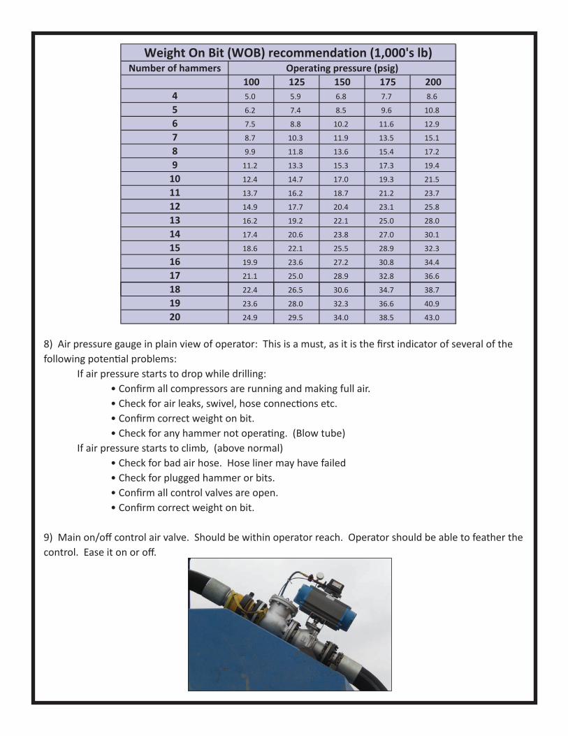
8) Air pressure gauge in plain view of operator: This is a must, as it is the first indicator of several of the following potential problems: If air pressure starts to drop while drilling: • Confirm all compressors are running and making full air. • Check for air leaks, swivel, hose connections etc. • Confirm correct weight on bit. • Check for any hammer not operating. (Blow tube) If air pressure starts to climb, (above normal) • Check for bad air hose. Hose liner may have failed • Check for plugged hammer or bits. • Confirm all control valves are open. • Confirm correct weight on bit.
9) Main on/off control air valve. Should be within operator reach. Operator should be able to feather the control. Ease it on or off.
Weight On Bit (WOB) recommendation (1,000's lb)Number of hammers Operating pressure (psig)
100 125 150 175 2004 5.0 5.9 6.8 7.7 8.6
5 6.2 7.4 8.5 9.6 10.8
6 7.5 8.8 10.2 11.6 12.9
7 8.7 10.3 11.9 13.5 15.1
8 9.9 11.8 13.6 15.4 17.2
9 11.2 13.3 15.3 17.3 19.4
10 12.4 14.7 17.0 19.3 21.5
11 13.7 16.2 18.7 21.2 23.7
12 14.9 17.7 20.4 23.1 25.8
13 16.2 19.2 22.1 25.0 28.0
14 17.4 20.6 23.8 27.0 30.1
15 18.6 22.1 25.5 28.9 32.3
16 19.9 23.6 27.2 30.8 34.4
17 21.1 25.0 28.9 32.8 36.6
18 22.4 26.5 30.6 34.7 38.7
19 23.6 28.0 32.3 36.6 40.9
20 24.9 29.5 34.0 38.5 43.0
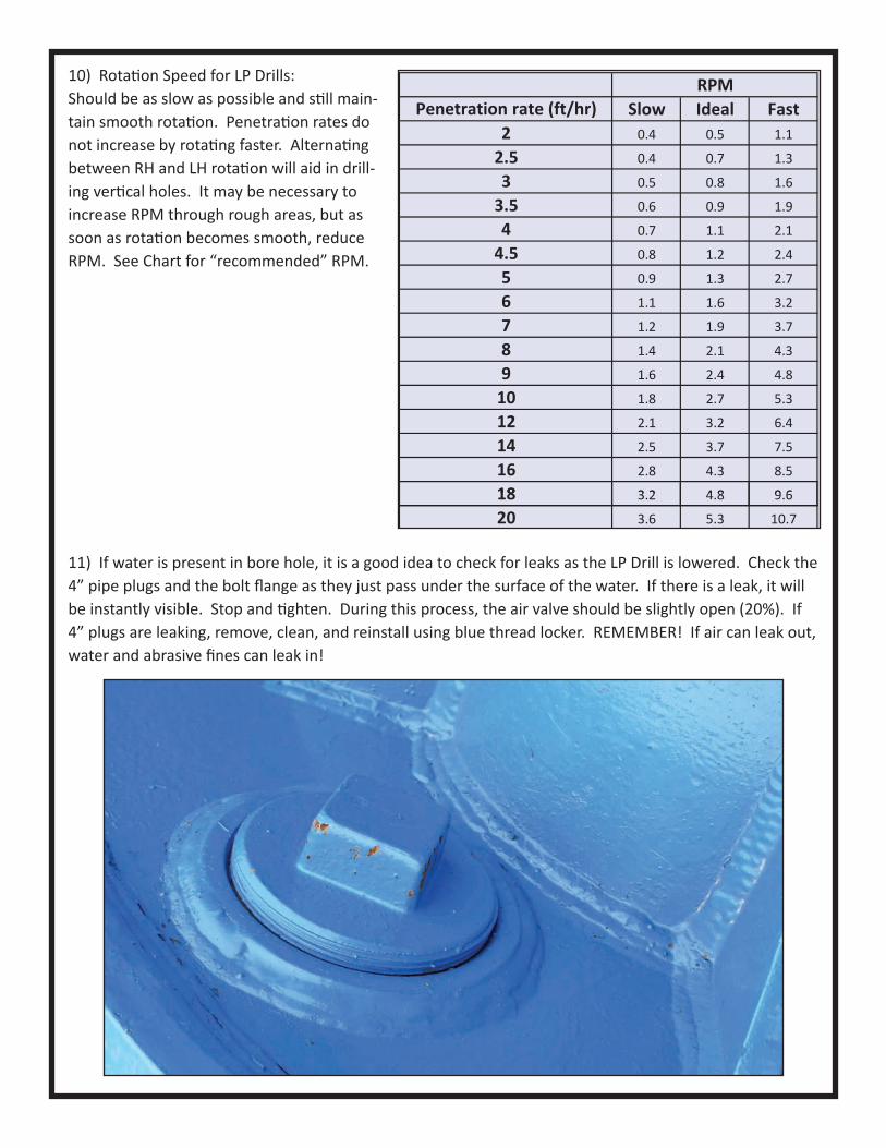
10) Rotation Speed for LP Drills:Should be as slow as possible and still main-tain smooth rotation. Penetration rates do not increase by rotating faster. Alternating between RH and LH rotation will aid in drill-ing vertical holes. It may be necessary to increase RPM through rough areas, but as soon as rotation becomes smooth, reduce RPM. See Chart for “recommended” RPM.
11) If water is present in bore hole, it is a good idea to check for leaks as the LP Drill is lowered. Check the 4” pipe plugs and the bolt flange as they just pass under the surface of the water. If there is a leak, it will be instantly visible. Stop and tighten. During this process, the air valve should be slightly open (20%). If 4” plugs are leaking, remove, clean, and reinstall using blue thread locker. REMEMBER! If air can leak out, water and abrasive fines can leak in!
18
RPMPenetration rate (ft/hr) Slow Ideal Fast
2 0.4 0.5 1.1
2.5 0.4 0.7 1.3
3 0.5 0.8 1.6
3.5 0.6 0.9 1.9
4 0.7 1.1 2.1
4.5 0.8 1.2 2.4
5 0.9 1.3 2.7
6 1.1 1.6 3.2
7 1.2 1.9 3.7
8 1.4 2.1 4.3
9 1.6 2.4 4.8
10 1.8 2.7 5.3
12 2.1 3.2 6.4
14 2.5 3.7 7.5
16 2.8 4.3 8.5
18 3 23.2 4 84.8 9 69.6
20 3.6 5.3 10.7
12) Once drilling has started, it is helpful if the following items are recorded early in the project: • Air pressure off bottom • Air pressure when contacting bottom. (All hammers may not be running.) • Air pressure after achieving flat bottom. (All hammers running.) • Weight on bit to start hole. • Weight on bit after flat bottom is achieved. • RPM and Torque • Penetration rate
13) Over the length of the project, compare above notes from the start of the project to current.Drop or rise in air pressure, higher than normal torque, very erratic rotation, slow down in penetration rate, are all indicators that something has changed.
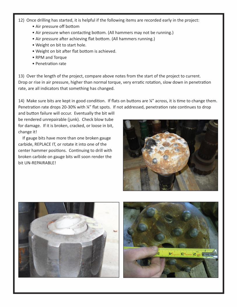
14) Make sure bits are kept in good condition. If flats on buttons are ¼” across, it is time to change them. Penetration rate drops 20-30% with ¼” flat spots. If not addressed, penetration rate continues to drop and button failure will occur. Eventually the bit will be rendered unrepairable (junk). Check blow tube for damage. If it is broken, cracked, or loose in bit, change it! If gauge bits have more than one broken gauge carbide, REPLACE IT, or rotate it into one of the center hammer positions. Continuing to drill with broken carbide on gauge bits will soon render the bit UN-REPAIRABLE!
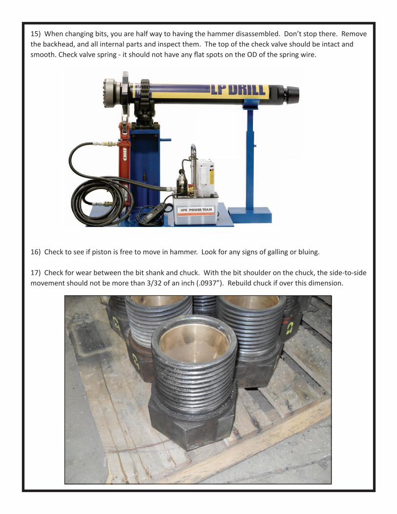
15) When changing bits, you are half way to having the hammer disassembled. Don’t stop there. Remove the backhead, and all internal parts and inspect them. The top of the check valve should be intact and smooth. Check valve spring - it should not have any fl at spots on the OD of the spring wire.
16) Check to see if piston is free to move in hammer. Look for any signs of galling or bluing.
17) Check for wear between the bit shank and chuck. With the bit shoulder on the chuck, the side-to-side movement should not be more than 3/32 of an inch (.0937”). Rebuild chuck if over this dimension.
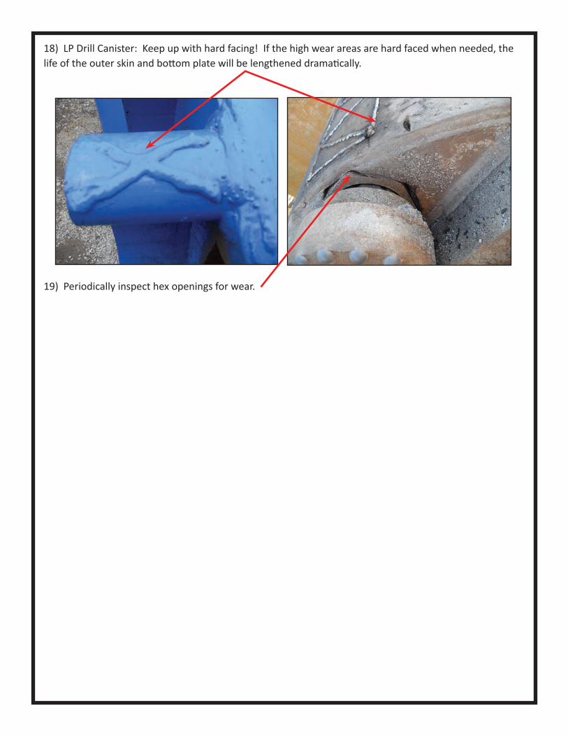
18) LP Drill Canister: Keep up with hard facing! If the high wear areas are hard faced when needed, the life of the outer skin and bottom plate will be lengthened dramatically.
19) Periodically inspect hex openings for wear.
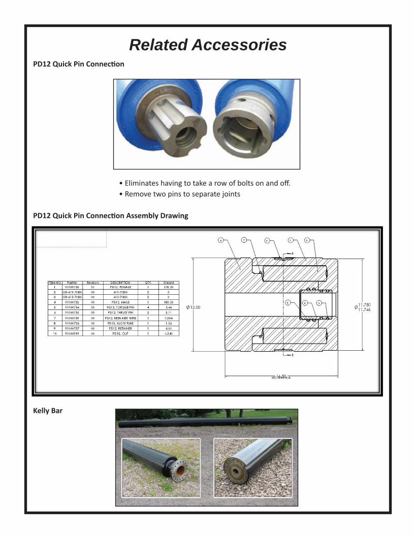
Related AccessoriesPD12 Quick Pin Connecti on
• Eliminates having to take a row of bolts on and off . • Remove two pins to separate joints
PD12 Quick Pin Connecti on Assembly Drawing
Kelly Bar

Related AccessoriesFlange Adaptor for Kelly Bar Ratchet Att achment
Swivel on a Drill