Embed Size (px)
Citation preview
Electric quarter turn actuator
CENTORK 480 Series Profibus DP
Installation and maintenance user’s manual

INSTALATION AND MAINTENACE USER MANUAL Pag 1
INTRODUCTION
electric actuators are a high value devices. In order to prevent damage in their handling,
setting and use it is essential to follow and observe all the points in this user manual, operate under actuators’ designated use, and observe the health and safety rules, standards and directives.
electric actuator must be handled with care and caution. Each actuator is delivered, by CENTORK Valve Control S.L., with the following documentation:
− Quarter turn electric actuator − Installation and maintenance quarter turn electric actuator user manual − Wiring diagram
In case any of this documentation is not available, contact with your distributor or CENTORK Valve Control S.L., CENTORK address is printed on the covers of this manual.
This pictogram advises and remarks activities, procedures and notes related to safety or a correct operation of this quarter turn actuator. Non-observance of these notes might lead to consequential damage.
IMPORTANT NOTE
This work and the information it contains are property of CENTORK Valve Control S.L.. The information it contains will not be reproduced or disclosed, in whole or in part, without the prior written consent of CENTORK.
The contents in this manual are subject to change due to the quality improvement without individual notice.

Pag 2 INSTALATION AND MAINTENACE USER MANUAL
INSTALATION AND MAINTENACE USER MANUAL Pag 3
Index 1 GENERAL DESCRIPTION........................................................................................................................5
1.1 Quarter turn electric actuator, with Profibus card controller..............................................................5 1.2 Standard Features ............................................................................................................................5 1.3 Profibus card controller features .......................................................................................................6 1.4 PROFIBUS card Controller ...............................................................................................................6
2 SAFETY INSTRUCTIONS.........................................................................................................................7 3 TRANSPORT AND STORAGE .................................................................................................................7
3.1 Transport and actuator handling .......................................................................................................7 3.2 Storage and commissioning..............................................................................................................7
4 PRE-INSTALLATION INSPECTION .........................................................................................................8 5 ACTUATOR MOUNTING ..........................................................................................................................8 6 ELECTRICAL CONNECTIONS.................................................................................................................9 7 PRELIMINARY TEST and settings............................................................................................................9
7.1 Sense of rotation ...............................................................................................................................9 7.1.1 Actuator-Valve sense of rotation:..................................................................................................9 7.1.2 Motor sense of rotation. ..............................................................................................................10
7.2 Handwheel and Declutching ...........................................................................................................10 7.3 Mechanical Travel Stop Adjustment ...............................................................................................10 7.4 Limit Switch Setting.........................................................................................................................11 7.5 Torque Switch Setting .....................................................................................................................11 7.6 Counter-Clockwise to Close Setting ...............................................................................................11 7.7 Mechanical Position indicator Setting .............................................................................................11 7.8 Potentiometer setting (Optional element) .......................................................................................12
8 LOCAL CONTROL UNIT (OPTIONAL) ...................................................................................................12 9 Profibus DP interface...............................................................................................................................13
9.1 Address and Node ..........................................................................................................................13 9.2 Auto-scan function (Modulating version Only) ................................................................................13 9.3 Actuator Model Setup......................................................................................................................13 9.4 Terminating Resistance Setup........................................................................................................13 9.5 LED Status Check-up......................................................................................................................14 9.6 PORT1, PORT2: (PROFIBUS Signal Line Incoming/Outgoing) ....................................................15 9.7 PROFIBUS SIGNAL LINE CONNECTION .....................................................................................15 9.8 OPERATION ...................................................................................................................................15 9.9 Protocol Designation .......................................................................................................................16
10 MAINTENANCE.......................................................................................................................................18 10.1 Lubrication.......................................................................................................................................18 10.2 Tools for installation and maintenance tasks..................................................................................18
11 TROUBLE SHOOTING............................................................................................................................19 11.1 Actuator does not respond..............................................................................................................19 11.2 Actuator is being powered but it does not operate .........................................................................19
12 AFTERSALES SERVICE.........................................................................................................................19 13 SPARE PARTS........................................................................................................................................20 14 ANNEXE ..................................................................................................................................................21

Pag 4 INSTALATION AND MAINTENACE USER MANUAL
INSTALATION AND MAINTENACE USER MANUAL Pag 5
1 GENERAL DESCRIPTION
1.1 Quarter turn electric actuator, with Profibus card controller Quarter turn electric actuators series are designed to provide reliable and efficient operation of 90-degree quarter turn valves. Other applications should be consulted CENTORK before. CENTORK is not liable for any possible damages resulting from use in other than designated applications. Such risk lies entirely on the user.
CENTORK Profibus card controller provides multiple communication function based on 8-Bit Micro-Process and Profibus Controller dedicated for multiple communication, it remotely takes signals that user sends and then provides status confirmation including normal/reverse operation. - As it is Dual Port, it is possible to construct System Redundancy and it provides high reliability.
Actuator torques range from 80Nm to 1.100Nm.
1.2 Standard Features Enclosure Rated Weatherproof IP67 according to EN60.529. IP68 optional.
Enclosure High grade aluminium alloy, corrosion coated
Power Supply 110/220VAC 1 PH 50/60Hz 380/440VAC 3PH 50/60Hz, 24 VDC
Control Power supply 110/220VAC 1 PH 50/60Hz, 24 VDC
Duty Cycle (ON-OFF) S2, 20-50% Máx 30 min, according to EN60034-1.
Duty Cycle (Modulating) S4, 30-50%, 300-1200 starts/hour, according to EN60034-1.
Motor Squirrel caged induction motor
Limit Switches Open/close SPDT, 250VAC 10A rating
Auxiliary Limit Switches Open/close SPDT, 250VAC 10A rating
Torque Switches Open/close SPDT, 250VAC 10A Rating (Not available in 480.007 and 480.010 models)
Stall Protection Built –in thermal protection, high 150ºC / low 97ºC ±15ºC
Travel Angle 90º ±5º
Indicator Continuous position indicator
Manual Override Declutchable manual override
Self Locking By means of worm gear
Mechanical Travel Stops 2 x external adjustable mechanical travel stops
Space Heater 5W (110/220V AC) anti-condensation heater.
Conduit Entries 2xM25 (except 480.007: 2xM20). NPT, PG optional)
Lubrication Grease moly EP
Ambient Temperature -20º C to + 70º C
External Coating Dry powder polyester. Dielectric strength 1500 V AC (1 min)
Terminal block Screw and lever push type
Notes:
− Features of some OPTIONAL elements are described in specific chapters. Elements such us potentiometers, transmitter, RPC positioner, LM2 local control…

Pag 6 INSTALATION AND MAINTENACE USER MANUAL
1.3 Profibus card controller features Communication: PROFIBUS (RS-485 Base)
PROFIBUS Signal Port: Incoming 2 Port / Outgoing 2 Port
Range: 1000m @ 9.6~187.5Kbps
Bit Rate: Up to 12Mbps
Output Contact: Triac, Max. AC 250V 10A (Inductive Load)
Ambient Humidity: 90% RH Max (Non-Condensing)
Voltage Withstand Test: 1500VAC, 1Min (Power to GND)
Insulation Resistance: 100MΩ or more / 500VDC
1.4 PROFIBUS card Controller CENTORK Profibus card controller provides multiple communication function based on 8-Bit Micro-Process and Profibus Controller dedicated for multiple communication, it remotely takes signals that user sends and then provides status confirmation including normal/reverse operation.
- The card controller output contact for driving motor provides high reliability that may be used semi-permanently as it is using semi conductor element.
- The Profibus card has the maximum 12 Mbps of transmitting speed. However, it may differ upon the length of the tracks/wires to be installed.
- CENTORK Profibus card controller is divided into ON/OFF Controller and Modulator Controller that is possible for position control. Firmware is installed accordingly as factory setup.
- As it is Dual Port, it is possible to construct System Redundancy and it provides high reliability.
- CENTORK Profibus card controller provides 7 LED lights that make users able to check the status of the Actuators:
A. Main Board 1. PORT1 (White) : Communication Status of Port1 2. PORT2 (Blue) : Communication Status of Port2 3. FAULT (Yellow) : Over Torque 4. CLOSE (Green) : Actuator’s Operation Status (Closing and/or Full Close)
5. OPEN (Red) : Actuator’s Operation Status (Opening &/or Full Open)
B. Profibus electronic Board
6. P1 (Green) : Communication Status of Port1 7. P2 (Green) : Communication Status of Port2
INSTALATION AND MAINTENACE USER MANUAL Pag 7
2 SAFETY INSTRUCTIONS The scope of this manual is to enable a competent user to install, operate, adjust and inspect a CENTORK quarter turn electric actuator. These instructions must be observed, otherwise a safe operation of the actuator is no longer warranted.
As electric device, during electrical operation certain parts inevitably carry lethal voltages and currents (ELECTRICAL RISKS). Work on the electrical system or equipment must only be carried out by a skilled electrician himself or by specially instructed personnel, in accordance with the applicable electrical engineering rules, health and safety Directives and any other national legislation applicable.
Under no circumstances should any modification or alteration be carried out on the actuator as this could very well invalidate the conditions which the device was designed.
Under operation, motor enclosure surfaces can reach high temperatures (up to 100ºC). Protection measures should be taken into acount in order to prevent people and goods from it.
3 TRANSPORT AND STORAGE
3.1 Transport and actuator handling
− CENTORK electric actuators must be transported in sturdy packing. During transport measures should be adopt in order to prevent impacts, hits. CENTORK delivers its actuators ex-work.
− Hits or impacts against wall, surfaces or objects might cause severe damage on Electric actuator. In these cases, after such events, a technical inspection must be done by CENTORK technicians.
− Do not attach to the handwheel ropes or hooks to lift by hoist. − The valve-actuator unit cannot be lifted/manipulated employing any lifting point of the actuator;
Actuator has been designed and sized in order to motorize industrial valves, and withstand the torque required.
− Covers have to be properly closed (Tight) and sealed. Cable entries on electrical connection cover must be sealed. Do not manipulate the protection plugs: Metallic protection plug are sealed with PTFE tape.
− Each Actuator is delivered with a set of technical documentation (User manual, datasheet, diagrams…), which has to be carefully stored.
3.2 Storage and commissioning Despite of their high degree of protection (IP67 as standard, and IP68 optional) condensation –presence of water- can occur inside the electric actuators by incorrect and negligent handling of the actuators. This may damage sensitive internal parts during the storage. This problem can be avoided by observing the following points. − Verify the actuator to insure correct model number, torque, options and special components,
voltage and enclosure type, and the actuator control before installation or use. It is important to verify that the actuator is appropriate for the requirements of the valve and the intended application. If there is any discrepancy, please contact with your local distributor, or CENTORK, to solve that discrepancy. Once the electric actuator has been set up, CENTORK decline any responsibility related to discrepancies.
Pag 8 INSTALATION AND MAINTENACE USER MANUAL
− While commissioning, CENTORK recommend a visual inspection in order to detect any anomaly caused during the transport, handling or during the storage; Checking should include a visual inspection of the switching and signalling unit compartment.
− Check that the painting work of the actuator is not been damaged. Retouch it when damaged. − Check that actuator cover is correctly closed ant tight. Check that protection plugs for the cable
entries are correctly closed ant tight. Protection plug must be sealed with PTFE tape. − If damages like shocks, cracks, hits or others due to an improper handling, or humidity inside the
equipment due to improper storage appear, contact CENTORK or your nearest distributor. − CENTORK quarter turn electric actuators are packed in sturdy packing: Store in a clean,
cool, dry and ventilated place. Protect against humidity from the floor. Use pallets, wooden frames, cage boxes or shelves. Do not store the actuator directly on the ground! Cover it to protect it from dust and dirt. Cover the machined parts with suitable protection against corrosion. Do not employ plastic bags, as they can cause condensation.
− Each Actuator is delivered with a set of technical documentation (User manual, datasheet, diagrams…), which has to be carefully stored.
4 PRE-INSTALLATION INSPECTION
− Verify the actuators nameplate to insure correct model number, torque, operating speed, options and special components, voltage and enclosure type before installation or use.
− It is important to verify that the output torque of the actuator is appropriate for the torque requirements of the valve and that the actuator duty cycle is appropriate for the intended application.
− If there is any discrepancy, please contact with your local distributor, or CENTORK, to solve that discrepancy. Once the electric actuator has been set up, CENTORK decline any responsibility related to discrepancies.
5 ACTUATOR MOUNTING
− Do not lift the actuator by the handwheel. Do not attach to the handwheel ropes or hooks to lift by hoist.
− The actuator may be mounted in any position
− The CENTORK quarter turn electric actuator Series are supplied with a female drive output. ISO5211. Bolt patterns are provided for actuator mounting. The actuator drive bush is removable for ease of machining (except fop 480.007). To remove the drive bush, just take out the 2 fixing screws bolts DIN912.
− It is mandatory that the actuator be firmly secured to a sturdy mounting bracket or directly mounted to the valve’s ISO mounting pad. High tensile bolts or studs with spring locking washers must be used.
− When required, the actuator output flange can be rotate 45º, in this case, it is necessary to release the 8 bolts (DIN912) that fix the flange to the actuator housing, and then, rotate the flange.
− The valve output shaft must be inline with the actuator output drive to avoid side-loading the shaft. To avoid any backlash no flexibility in the mounting bracket or mounting should be allowed.
− Reserve the space for maintenance routines and tasks.
INSTALATION AND MAINTENACE USER MANUAL Pag 9
6 ELECTRICAL CONNECTIONS
Safety instructions on chapter 2 must be observed. Work on electrical system or equipment must only be carried out by skilled electrician.
Wiring diagram is enclosed inside the quarter turn electric actuator (Electric compartment) Just in case the wiring diagram is missing, contact with your distributor or CENTORK Valve Control. Observe the max. allowable current/voltage values of electric devices (Microswitches, heater, transmitter…)
− Standard factory units are anti-clockwise to open!
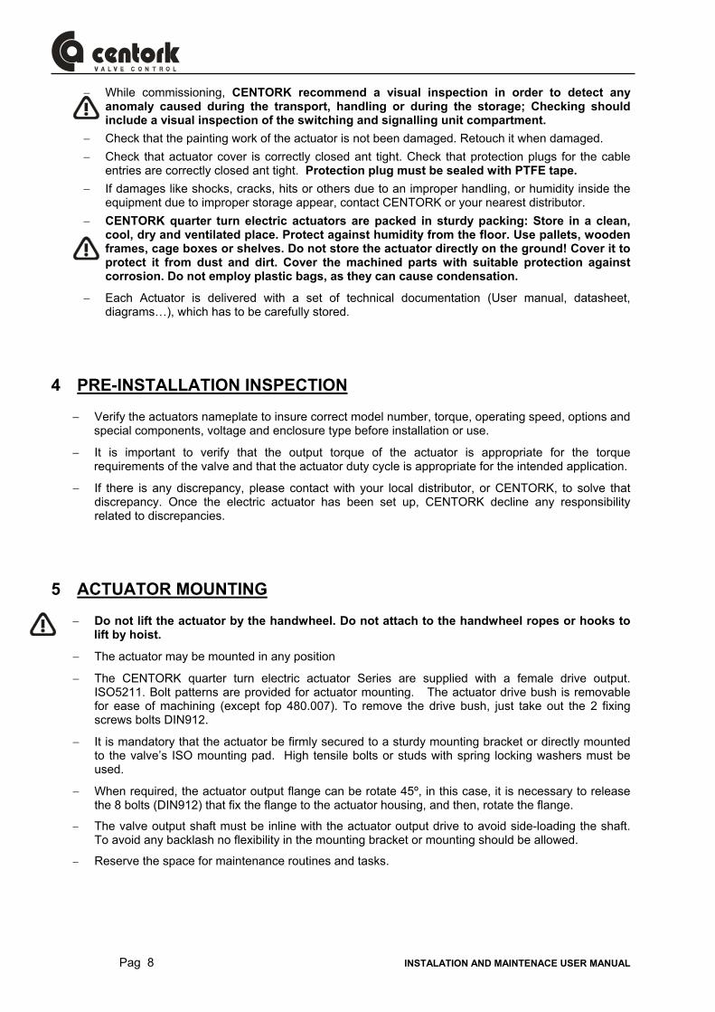
− Loosen the screws on the actuator cover and lift it off.
− Make sure that power supply voltage is in accordance with the data on the actuator nameplate
− Use and install proper cable glands and protection plug, according to IP protection degree. Seal properly the cable glands. Warranty is no longer valid if this is not respected.
− Pass cables through cable glands.
− Connect according to the enclosed wiring diaphragm. Employ a proper screw driver in order to release the terminals. Wire should be 8~9 mm maximum.
− Check that all cable glands are correctly tighten
− Clean sealing faces at terminal cover and check whether O-ring is in good condition. Mount cover and tighten cover bolts.
Power Requirements: Consult the nameplate of the actuator for duty cycle and current draw information
Duty Cycle: Duty cycle rated IEC34 – S2 or S4 (See standard features chapter), exceeding the actuator’s rated duty cycle may cause thermal overload.
7 PRELIMINARY TEST AND SETTINGS
− Move the valve manually to an half-open position, operate an electrical opening and check that the motor rotates in the right direction (Visual disc indicator or valve shaft could help for this). Stop immediately if NOT. Instructions have been made for standard electric actuators: CLOCKWISE TO CLOSE
− Test run the actuator and check that the limit switches work correctly
− Check that all cable glands are correctly tighten.
− Clean sealing surfaces at terminal cover and check whether O-ring is in good condition. Mount cover and tighten cover bolts.
7.1 Sense of rotation
7.1.1 Actuator-Valve sense of rotation:
− Run the actuator manually (See 7.2 chapter) by mean of the handwheel. When turning the handwheel clockwise, valve must close. Also, check that actuator visual indication disc rotates clockwise as well: This means that valve and actuator are CLOCKWISE-TO CLOSE.
− In case that turning the actuator handwheel valve opens instead of closing, that means that sense of rotation (valve and actuator) is COUNTER-CLOCKWISE-TO-CLOSE. In this case, ACTUATOR needs to be reconfigured as a COUNTER-CLOCKWISE (See 7.6 chapter)
Pag 10 INSTALATION AND MAINTENACE USER MANUAL
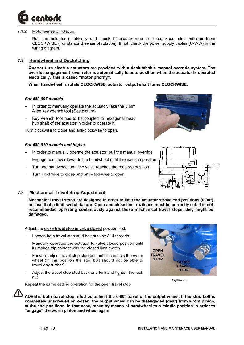
Figure 7.3
7.1.2 Motor sense of rotation.
− Run the actuator electrically and check if actuator runs to close, visual disc indicator turns CLOCKWISE (For standard sense of rotation). If not, check the power supply cables (U-V-W) in the wiring diagram.
7.2 Handwheel and Declutching Quarter turn electric actuators are provided with a declutchable manual override system. The override engagement lever returns automatically to auto position when the actuator is operated electrically, this is called “motor priority”.
When handwheel is rotate CLOCKWISE, actuator output shaft turns CLOCKWISE.
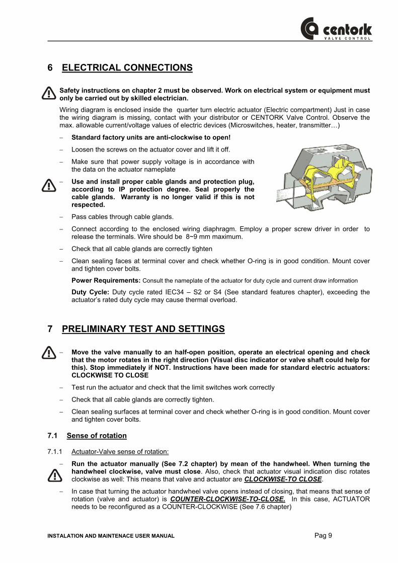
For 480.007 models
− In order to manually operate the actuator, take the 5 mm Allen key wrench tool (See picture)
− Key wrench tool has to be coupled to hexagonal head hub shaft of the actuator in order to operate it.
Turn clockwise to close and anti-clockwise to open.
For 480.010 models and higher
− In order to manually operate the actuator, pull the manual override
− Engagement lever towards the handwheel until it remains in position.
− Turn the handwheel until the valve reaches the required position
− Turn clockwise to close and anti-clockwise to open
7.3 Mechanical Travel Stop Adjustment Mechanical travel stops are designed in order to limit the actuator stroke end positions (0-90º) in case that a limit switch failure. Open and close limit switches must be correctly set. It is not recommended operating continuously against these mechanical travel stops, they might be damaged.
Adjust the close travel stop in valve closed position first.
− Loosen both travel stop stud bolt nuts by 3~4 threads
− Manually operated the actuator to valve closed position until its makes trip contact with the closed limit switch.
− Forward adjust travel stop stud bolt until it contacts the worm wheel (In this position the stud bolt should not be able to travel any further).
− Adjust the travel stop stud back one turn and tighten the lock nut
Repeat the same setting operation for the open travel stop
ADVISE: both travel stop stud bolts limit the 0-90º travel of the output wheel. If the stud bolt is completely unscrewed or loosen, the output wheel can be disengaged (gear) from wrom pinion, at the end positions. In that case, move by means of handwheel to a middle position in order to “engage” the worm pinion and wheel again.
OPENTRAVEL
STOPCLOSE TRAVEL
STOP
INSTALATION AND MAINTENACE USER MANUAL Pag 11
480.010 models and higher
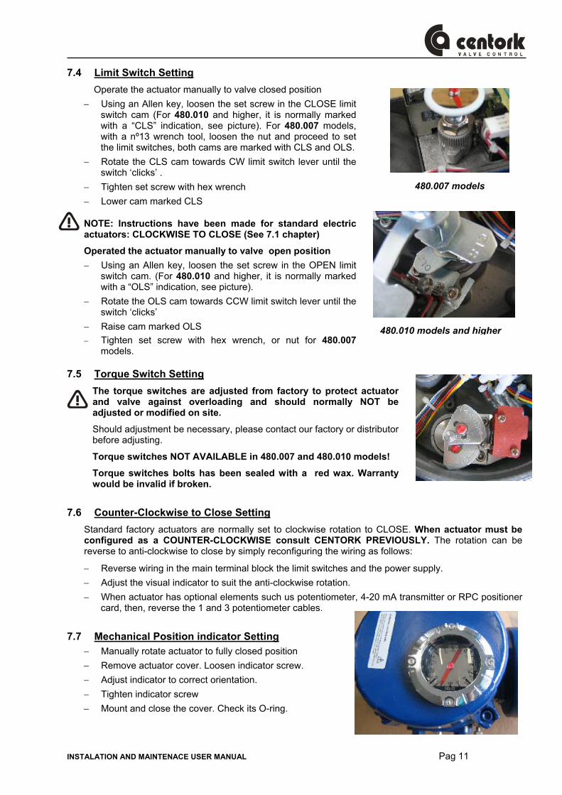
480.007 models
7.4 Limit Switch Setting Operate the actuator manually to valve closed position
− Using an Allen key, loosen the set screw in the CLOSE limit switch cam (For 480.010 and higher, it is normally marked with a “CLS” indication, see picture). For 480.007 models, with a nº13 wrench tool, loosen the nut and proceed to set the limit switches, both cams are marked with CLS and OLS.
− Rotate the CLS cam towards CW limit switch lever until the switch ‘clicks’ .
− Tighten set screw with hex wrench − Lower cam marked CLS
NOTE: Instructions have been made for standard electric actuators: CLOCKWISE TO CLOSE (See 7.1 chapter)
Operated the actuator manually to valve open position − Using an Allen key, loosen the set screw in the OPEN limit
switch cam. (For 480.010 and higher, it is normally marked with a “OLS” indication, see picture).
− Rotate the OLS cam towards CCW limit switch lever until the switch ‘clicks’
− Raise cam marked OLS − Tighten set screw with hex wrench, or nut for 480.007
models.
7.5 Torque Switch Setting The torque switches are adjusted from factory to protect actuator and valve against overloading and should normally NOT be adjusted or modified on site.
Should adjustment be necessary, please contact our factory or distributor before adjusting.
Torque switches NOT AVAILABLE in 480.007 and 480.010 models!
Torque switches bolts has been sealed with a red wax. Warranty would be invalid if broken.
7.6 Counter-Clockwise to Close Setting Standard factory actuators are normally set to clockwise rotation to CLOSE. When actuator must be configured as a COUNTER-CLOCKWISE consult CENTORK PREVIOUSLY. The rotation can be reverse to anti-clockwise to close by simply reconfiguring the wiring as follows:
− Reverse wiring in the main terminal block the limit switches and the power supply. − Adjust the visual indicator to suit the anti-clockwise rotation. − When actuator has optional elements such us potentiometer, 4-20 mA transmitter or RPC positioner
card, then, reverse the 1 and 3 potentiometer cables.
7.7 Mechanical Position indicator Setting − Manually rotate actuator to fully closed position − Remove actuator cover. Loosen indicator screw. − Adjust indicator to correct orientation. − Tighten indicator screw − Mount and close the cover. Check its O-ring.
Pag 12 INSTALATION AND MAINTENACE USER MANUAL
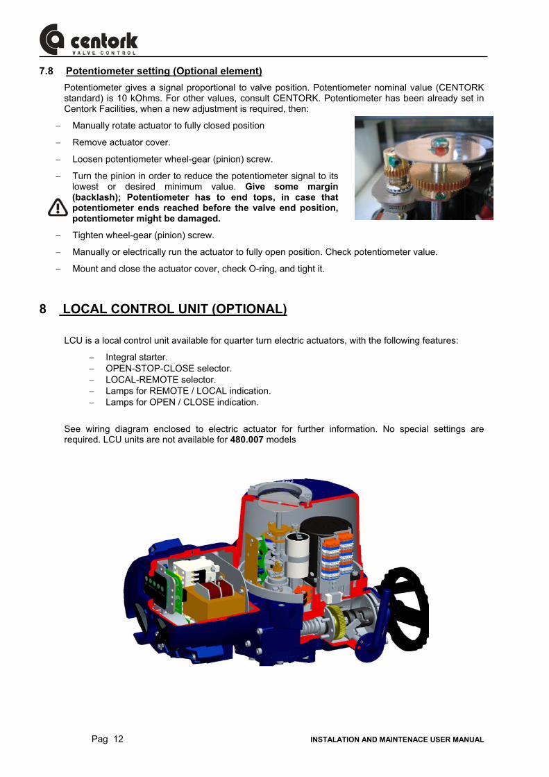
7.8 Potentiometer setting (Optional element) Potentiometer gives a signal proportional to valve position. Potentiometer nominal value (CENTORK standard) is 10 kOhms. For other values, consult CENTORK. Potentiometer has been already set in Centork Facilities, when a new adjustment is required, then:
− Manually rotate actuator to fully closed position
− Remove actuator cover.
− Loosen potentiometer wheel-gear (pinion) screw.
− Turn the pinion in order to reduce the potentiometer signal to its lowest or desired minimum value. Give some margin (backlash); Potentiometer has to end tops, in case that potentiometer ends reached before the valve end position, potentiometer might be damaged.
− Tighten wheel-gear (pinion) screw.
− Manually or electrically run the actuator to fully open position. Check potentiometer value.
− Mount and close the actuator cover, check O-ring, and tight it.
8 LOCAL CONTROL UNIT (OPTIONAL)
LCU is a local control unit available for quarter turn electric actuators, with the following features:
− Integral starter. − OPEN-STOP-CLOSE selector. − LOCAL-REMOTE selector. − Lamps for REMOTE / LOCAL indication. − Lamps for OPEN / CLOSE indication.
See wiring diagram enclosed to electric actuator for further information. No special settings are required. LCU units are not available for 480.007 models
INSTALATION AND MAINTENACE USER MANUAL Pag 13
9 Profibus DP interface
9.1 Address and Node Node: This means a device that has its own address in link with the master of Profibus, in this manual, Node means Actuator.
- Every Node that is linked in Profibus network has its own numbers each and this number is called Address. Address can be designated upper 0-9 and lower 0-9 as well. Address can be designated up to 99 at maximum as the upper is for the tens and the lower is for the units.
- Theoretically, it is possible to designate up to 124 but it is possible to designate up to 99 for this device.
- Since the address “0 (zero) is an unique address that does some separate function, this address (0) should not be setup on the actuator.
- If two (2) or more same addresses are duplicated, it is not able to communicate. Also, it may affect other “Nodes (slaves) communication and causes malfunction so please be noticed.
9.2 Auto-scan function (Modulating version Only) Auto-scan function automatically searches/detects the actuator’s position (Full Close and Full Open) and measures the operational range.
- In order to operate Auto-scan, remotely transmit the signal “Auto Setting Start” or press the button ASCN for about 2 seconds. (See Profibus card controller, 9.5 chapter)
- In order to cancel Auto-scan, remotely transmit the signal “Auto Setting Cancel” or press the button ASCN for about 2 seconds.
- Once Auto-scan carried out, the position values (factors) of Full Close and Full Open that were previously saved will be deleted and such new positions searched will be saved so please be noticed when operating Auto-scan.
- Operate/carry-out one time only when changing Controller Card, adjusting Limit Switch cam, changing Potentiometer, or initial setting up.
- Auto-scan is operated in the factory before shipping out so it is proper for the equipment so do NOT randomly re-operate.
9.3 Actuator Model Setup Please properly set up upon the type of the Actuator that the Controller will be installed on.
- Quarter Turn Actuator, 480 series (Model Switch: Position “ON”). (See Profibus card controller, 9.5 chapter)
- Linear Actuator, 490 series (Model Switch: Position “OFF”)
NOTE: It is properly set up upon the type of the Actuator to be installed in the factory before shipping out so please do NOT randomly change. If anything randomly changed while in use, it may cause malfunction so please be noticed.
9.4 Terminating Resistance Setup - Since Terminating Resistance is built in, it is not necessary to install a separate
Terminating Resistance. - If the equipment is installed at the end of Node in the connection status of track wiring, set
up the Dip Switch on direction “TERM” so that terminating resistance is setup. (See Profibus card controller, 9.5 chapter)
- Please be noticed that the equipment is installed at the end upon Profibus signal track structure (not upon the last number of Address).
Pag 14 INSTALATION AND MAINTENACE USER MANUAL
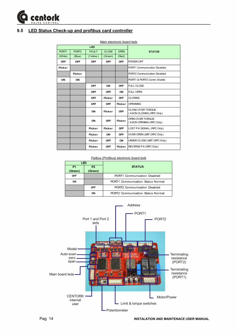
9.5 LED Status Check-up and profibus card controller
Main electronic board leds
PORT1 PORT2 FAULT CLOSE OPEN
(White) (Blue) (Yellow ) (Green) (Red)
OFF OFF OFF OFF OFF POWER OFF
Flicker PORT1 Communication Disabled
Flicker PORT2 Communication Disabled
ON ON PORT1 & PORT2 Comm. Enable
OFF ON OFF FULL CLOSE
OFF OFF ON FULL OPEN
OFF Flicker OFF CLOSING
OFF OFF Flicker OPENNING
ON Flicker OFF CLOSE OVER TORQUE / ASCN CLOSING (RPC Only)
ON OFF Flicker OPEN OVER TORQUE / ASCN OPENING (RPC Only)
Flicker Flicker OFF LOST P.K SIGNAL (RPC Only)
Flicker ON OFF OVER OPEN LIMIT (RPC Only)
Flicker OFF ON UNDER CLOSE LIMIT (RPC Only)
Flicker OFF Flicker REVERSE P.K (RPC Only)
LED
STATUS
Fielbus (Profibus) electronic board leds
P1 (Green)
P2 (Green)
OFF PORT1 Communication Disabled
ON PORT1 Communication Status Normal
OFF PORT2 Communication Disabled
ON PORT2 Communication Status Normal
STATUS LED
PORT1
Terminatingresistance(PORT1)
Terminatingresistance(PORT2)
PORT2
Potentiometer
CENTORKinternal
user
Model
Port 1 and Port 2leds
Auto-scanzerospan
Main board leds
Limit & torque switches
Motor/Power
Address
INSTALATION AND MAINTENACE USER MANUAL Pag 15
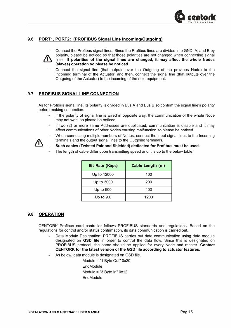
9.6 PORT1, PORT2: (PROFIBUS Signal Line Incoming/Outgoing)
- Connect the Profibus signal lines. Since the Profibus lines are divided into GND, A, and B by polarity, please be noticed so that those polarities are not changed when connecting signal lines. If polarities of the signal lines are changed, it may affect the whole Nodes (slaves) operation so please be noticed.
- Connect the signal line (that outputs over the Outgoing of the previous Node) to the Incoming terminal of the Actuator, and then, connect the signal line (that outputs over the Outgoing of the Actuator) to the incoming of the next equipment.
9.7 PROFIBUS SIGNAL LINE CONNECTION As for Profibus signal line, its polarity is divided in Bus A and Bus B so confirm the signal line’s polarity before making connection.
- If the polarity of signal line is wired in opposite way, the communication of the whole Node may not work so please be noticed.
- If two (2) or more same Addresses are duplicated, communication is disable and it may affect communications of other Nodes causing malfunction so please be noticed.
- When connecting multiple numbers of Nodes, connect the input signal lines to the Incoming terminals and the output signal lines to the Outgoing terminals.
- Such cables (Twisted Pair and Shielded) dedicated for Profibus must be used. - The length of cable differ upon transmitting speed and it is up to the below table.
Bit Rate (Kbps) Cable Length (m)
Up to 12000 100
Up to 3000 200
Up to 500 400
Up to 9.6 1200
9.8 OPERATION CENTORK Profibus card controller follows PROFIBUS standards and regulations. Based on the regulations for control and/or status confirmation, its data communication is carried out.
- Data Module Designation: PROFIBUS carries out data communication using data module designated on GSD file in order to control the data flow. Since this is designated on PROFIBUS protocol, the same should be applied for every Node and master. Contact CENTORK for the latest version of the GSD file according to actuator features.
- As below, data module is designated on GSD file. Module = "1 Byte Out" 0x20 EndModule Module = "3 Byte In" 0x12 EndModule
Pag 16 INSTALATION AND MAINTENACE USER MANUAL
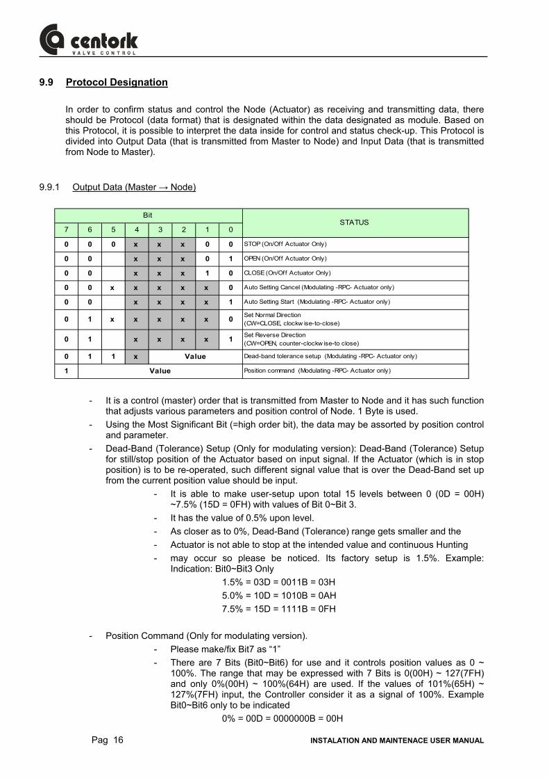
9.9 Protocol Designation In order to confirm status and control the Node (Actuator) as receiving and transmitting data, there should be Protocol (data format) that is designated within the data designated as module. Based on this Protocol, it is possible to interpret the data inside for control and status check-up. This Protocol is divided into Output Data (that is transmitted from Master to Node) and Input Data (that is transmitted from Node to Master).
9.9.1 Output Data (Master → Node)
7 6 5 4 3 2 1 0
0 0 0 x x x 0 0 STOP (On/Off Actuator Only)
0 0 x x x 0 1 OPEN (On/Off Actuator Only)
0 0 x x x 1 0 CLOSE (On/Off Actuator Only)
0 0 x x x x x 0 Auto Setting Cancel (Modulating -RPC- Actuator only)
0 0 x x x x 1 Auto Setting Start (Modulating -RPC- Actuator only)
0 1 x x x x x 0 Set Normal Direction(CW=CLOSE, clockw ise-to-close)
0 1 x x x x 1 Set Reverse Direction(CW=OPEN, counter-clockw ise-to close)
0 1 1 x Dead-band tolerance setup (Modulating -RPC- Actuator only)
1 Position command (Modulating -RPC- Actuator only)
Bit STATUS
Value
Value
- It is a control (master) order that is transmitted from Master to Node and it has such function that adjusts various parameters and position control of Node. 1 Byte is used.
- Using the Most Significant Bit (=high order bit), the data may be assorted by position control and parameter.
- Dead-Band (Tolerance) Setup (Only for modulating version): Dead-Band (Tolerance) Setup for still/stop position of the Actuator based on input signal. If the Actuator (which is in stop position) is to be re-operated, such different signal value that is over the Dead-Band set up from the current position value should be input.
- It is able to make user-setup upon total 15 levels between 0 (0D = 00H) ~7.5% (15D = 0FH) with values of Bit 0~Bit 3.
- It has the value of 0.5% upon level. - As closer as to 0%, Dead-Band (Tolerance) range gets smaller and the - Actuator is not able to stop at the intended value and continuous Hunting - may occur so please be noticed. Its factory setup is 1.5%. Example:
Indication: Bit0~Bit3 Only 1.5% = 03D = 0011B = 03H 5.0% = 10D = 1010B = 0AH 7.5% = 15D = 1111B = 0FH
- Position Command (Only for modulating version).
- Please make/fix Bit7 as “1” - There are 7 Bits (Bit0~Bit6) for use and it controls position values as 0 ~
100%. The range that may be expressed with 7 Bits is 0(00H) ~ 127(7FH) and only 0%(00H) ~ 100%(64H) are used. If the values of 101%(65H) ~ 127%(7FH) input, the Controller consider it as a signal of 100%. Example Bit0~Bit6 only to be indicated
0% = 00D = 0000000B = 00H
INSTALATION AND MAINTENACE USER MANUAL Pag 17
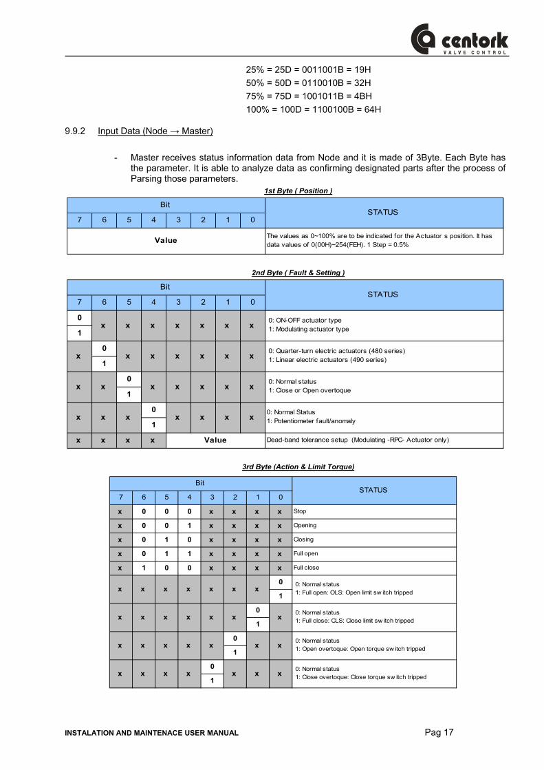
25% = 25D = 0011001B = 19H 50% = 50D = 0110010B = 32H 75% = 75D = 1001011B = 4BH 100% = 100D = 1100100B = 64H
9.9.2 Input Data (Node → Master)
- Master receives status information data from Node and it is made of 3Byte. Each Byte has the parameter. It is able to analyze data as confirming designated parts after the process of Parsing those parameters.
1st Byte ( Position )
7 6 5 4 3 2 1 0
The values as 0~100% are to be indicated for the Actuators position. It has data values of 0(00H)~254(FEH). 1 Step = 0.5%
Bit STATUS
Value
2nd Byte ( Fault & Setting )
7 6 5 4 3 2 1 0
0
1
0
1
0
1
0
1
x x x x Dead-band tolerance setup (Modulating -RPC- Actuator only)
x x
Bit STATUS
0: ON-OFF actuator type 1: Modulating actuator typex x x x x
x x x x x x
x x x x x x x
x x
Value
x
0: Quarter-turn electric actuators (480 series) 1: Linear electric actuators (490 series)
0: Normal status 1: Close or Open overtoque
0: Normal Status1: Potentiometer fault/anomalyx x x x
x
3rd Byte (Action & Limit Torque)
7 6 5 4 3 2 1 0
x 0 0 0 x x x x Stop
x 0 0 1 x x x x Opening
x 0 1 0 x x x x Closing
x 0 1 1 x x x x Full open
x 1 0 0 x x x x Full close
0
1
0
1
0
1
0
1
x 0: Normal status 1: Full close: CLS: Close limit sw itch tripped
x
x x x x
Bit STATUS
x x x x x x 0: Normal status 1: Full open: OLS: Open limit sw itch tripped
x x 0: Normal status 1: Open overtoque: Open torque sw itch trippedx x x x
x x 0: Normal status 1: Close overtoque: Close torque sw itch trippedx x x x
x
x
x
x
Pag 18 INSTALATION AND MAINTENACE USER MANUAL
10 MAINTENANCE
Maintenance, under normal conditions at six month intervals. But when conditions are more severe, more frequent inspections may be advisable.
− Ensure valve actuator alignment
− Insure wiring is insulated, connected and terminated properly
− Insure all screws are present and tight
− Insure cleanliness of internal electrical devices
− Insure conduit connections are installed properly and are dry
− Check internal devices for condensation(Presence of water) / humidity
− Check power to internal heater
− Check enclosure O rings sealing and verify that the O ring is not pinched/damaged between flange
− Verify declutch mechanism
− Visually inspect during open/close cycle
− Inspect identification labels for wear and replace if necessary
10.1 Lubrication 480 Series electric actuator is a totally enclosed unit with a permanently lubricated gear train (Moly EP Grease). Once installed lubrication should not be required. However, periodic preventative maintenance will extend the operating life of the actuator.
10.2 Tools for installation and maintenance tasks − 1 Set of Metric Allen Keys
− 1 Set of Screwdrivers
− 1 Metric Spanner
− 1 Wrench 200mm
− 1 Wrench 300mm
− 1 Wire Stripper (long Nose)
− 1 Multi Meter (AC, DC, Resistance), and 4-20 mA pocket generator.
INSTALATION AND MAINTENACE USER MANUAL Pag 19
11 TROUBLE SHOOTING
The following instructions are offered for the most common difficulties encounter during installation and start-up.
11.1 Actuator does not respond − Verify the line voltage (Power supply) to the actuator
− Check that the voltage matches the rating on the actuator nameplate
− Check internal wiring against actuator wiring diagram
− Check limit switch cams: Limit switches might not be correctly set
− Check torque switches: Jamming might happen
11.2 Actuator is being powered but it does not operate − Verify the line voltage to the actuator
− Check actuator torque to see if it’s greater than the valve torque: Actuator might be undersized.
− Check limit switches and cams
− Check that the torque switches are not tripped
− Check mechanical travel stop adjustment
− Verify the actuator against valve rotation (standard units are anti-clockwise to open)
− Check internal wiring
− Check for corrosion and condensation.
− Check that motor is not warm (Overheat).
− Verify coupler/bracket are correctly installed and is not causing binding
12 AFTERSALES SERVICE Each actuator is identified by a serial number located on nameplates. With each actuator the following information is included:
− The nameplates attached to the actuator. − The electric connection diagram for each actuator, inside of the electric cover. − This 480 Series electric quarter-turn actuator user’s manual.
For any claim or information request, the SERIAL NUMBER should be used. Should user have any further queries, please contact CENTORK thought phone, fax or e-mail without hesitation. CENTORK address can be found on Manual covers.
Pag 20 INSTALATION AND MAINTENACE USER MANUAL
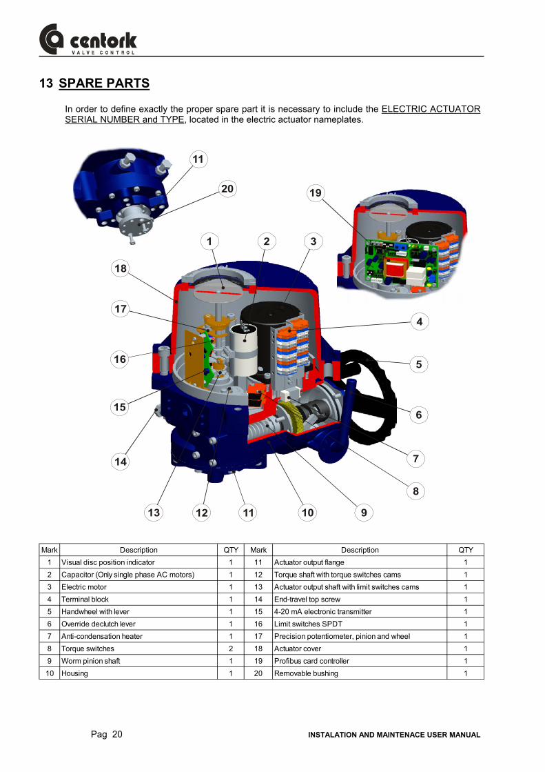
13 SPARE PARTS In order to define exactly the proper spare part it is necessary to include the ELECTRIC ACTUATOR SERIAL NUMBER and TYPE, located in the electric actuator nameplates.
1 2
4
5
6
7
8
111213
14
17
18
10 9
15
16
20
11
3
19
Mark Description QTY Mark Description QTY1 Visual disc position indicator 1 11 Actuator output flange 12 Capacitor (Only single phase AC motors) 1 12 Torque shaft with torque switches cams 13 Electric motor 1 13 Actuator output shaft with limit switches cams 14 Terminal block 1 14 End-travel top screw 15 Handwheel with lever 1 15 4-20 mA electronic transmitter 16 Override declutch lever 1 16 Limit switches SPDT 17 Anti-condensation heater 1 17 Precision potentiometer, pinion and wheel 18 Torque switches 2 18 Actuator cover 19 Worm pinion shaft 1 19 Profibus card controller 110 Housing 1 20 Removable bushing 1
INSTALATION AND MAINTENACE USER MANUAL Pag 21
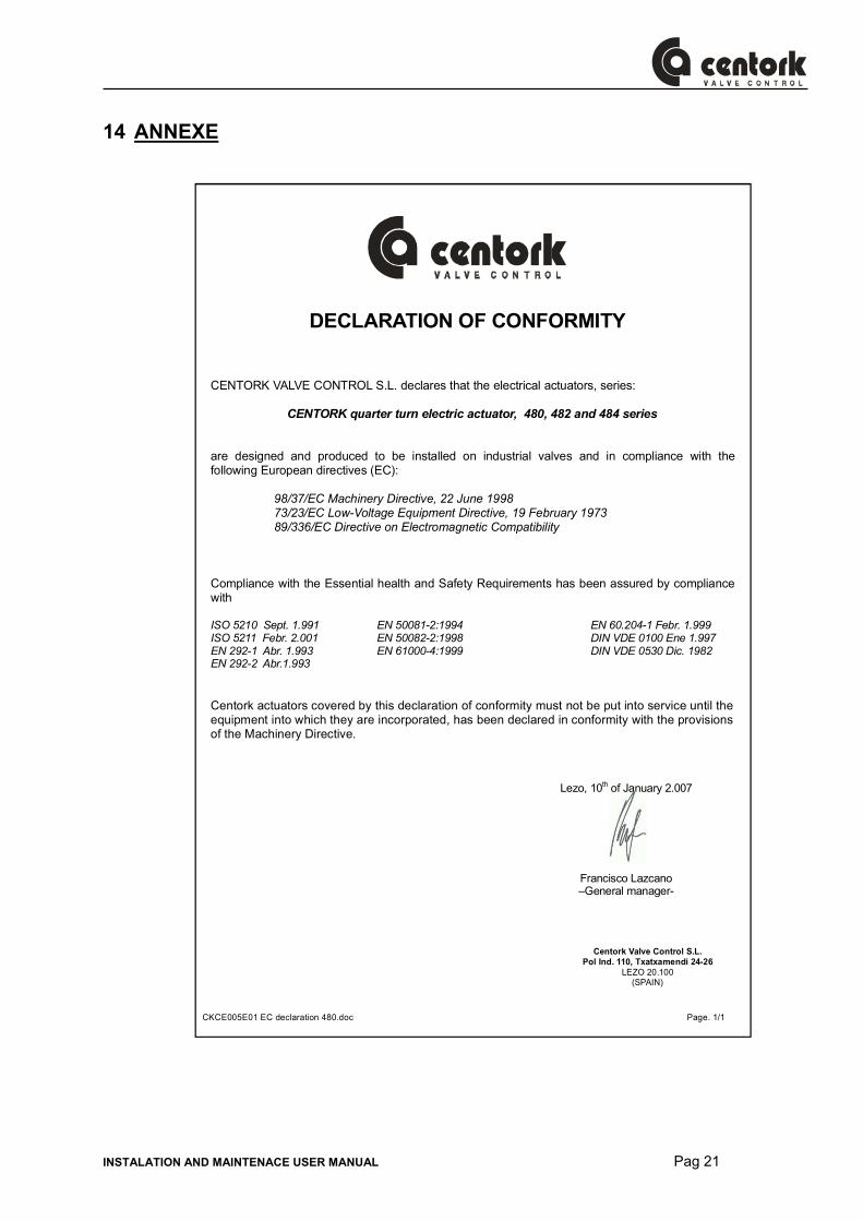
14 ANNEXE
CKCE005E01 EC declaration 480.doc Page. 1/1
DECLARATION OF CONFORMITY
CENTORK VALVE CONTROL S.L. declares that the electrical actuators, series:
CENTORK quarter turn electric actuator, 480, 482 and 484 series
are designed and produced to be installed on industrial valves and in compliance with the following European directives (EC):
98/37/EC Machinery Directive, 22 June 1998 73/23/EC Low-Voltage Equipment Directive, 19 February 1973 89/336/EC Directive on Electromagnetic Compatibility
Compliance with the Essential health and Safety Requirements has been assured by compliance with
ISO 5210 Sept. 1.991 ISO 5211 Febr. 2.001 EN 292-1 Abr. 1.993 EN 292-2 Abr.1.993
EN 50081-2:1994 EN 50082-2:1998 EN 61000-4:1999
EN 60.204-1 Febr. 1.999 DIN VDE 0100 Ene 1.997 DIN VDE 0530 Dic. 1982
Centork actuators covered by this declaration of conformity must not be put into service until the
equipment into which they are incorporated, has been declared in conformity with the provisions of the Machinery Directive.
Lezo, 10th of January 2.007
Francisco Lazcano –General manager-
Centork Valve Control S.L. Pol Ind. 110, Txatxamendi 24-26
LEZO 20.100 (SPAIN)
Pag 22 INSTALATION AND MAINTENACE USER MANUAL
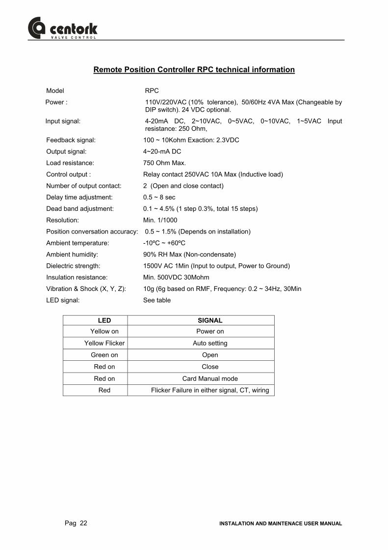
Remote Position Controller RPC technical information
Model RPC
Power : 110V/220VAC (10% tolerance), 50/60Hz 4VA Max (Changeable by DIP switch). 24 VDC optional.
Input signal: 4-20mA DC, 2~10VAC, 0~5VAC, 0~10VAC, 1~5VAC Input resistance: 250 Ohm,
Feedback signal: 100 ~ 10Kohm Exaction: 2.3VDC
Output signal: 4~20-mA DC
Load resistance: 750 Ohm Max.
Control output : Relay contact 250VAC 10A Max (Inductive load)
Number of output contact: 2 (Open and close contact)
Delay time adjustment: 0.5 ~ 8 sec
Dead band adjustment: 0.1 ~ 4.5% (1 step 0.3%, total 15 steps)
Resolution: Min. 1/1000
Position conversation accuracy: 0.5 ~ 1.5% (Depends on installation)
Ambient temperature: -10ºC ~ +60ºC
Ambient humidity: 90% RH Max (Non-condensate)
Dielectric strength: 1500V AC 1Min (Input to output, Power to Ground)
Insulation resistance: Min. 500VDC 30Mohm
Vibration & Shock (X, Y, Z): 10g (6g based on RMF, Frequency: 0.2 ~ 34Hz, 30Min
LED signal: See table
LED SIGNAL
Yellow on Power on
Yellow Flicker Auto setting
Green on Open
Red on Close
Red on Card Manual mode
Red Flicker Failure in either signal, CT, wiring
INSTALATION AND MAINTENACE USER MANUAL Pag 23
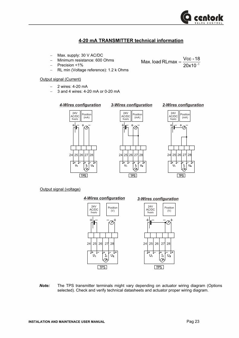
4-20 mA TRANSMITTER technical information
− Max. supply: 30 V AC/DC − Minimum resistance: 600 Ohms − Precision <1% − RL min (Voltage reference): 1.2 k Ohms
Output signal (Current)
− 2 wires: 4-20 mA − 3 and 4 wires: 4-20 mA or 0-20 mA
24VAC/DCSupply
24VAC/DCSupply
24VAC/DCSupply
Position(mA)
Position(mA)
Position(mA)
4-Wires configuration 3-Wires configuration 2-Wires configuration
24 24 2425 25 2526 26 2627 27 2728 28 28
Output signal (voltage)
24VAC/DCSupply
24VAC/DCSupply
Position(V)
Position(V)
4-Wires configuration 3-Wires configuration
24 2425 2526 2627 2728 28
Note: The TPS transmitter terminals might vary depending on actuator wiring diagram (Options
selected). Check and verify technical datasheets and actuator proper wiring diagram.
3-20x1018-Vcc RLmax load Max. =

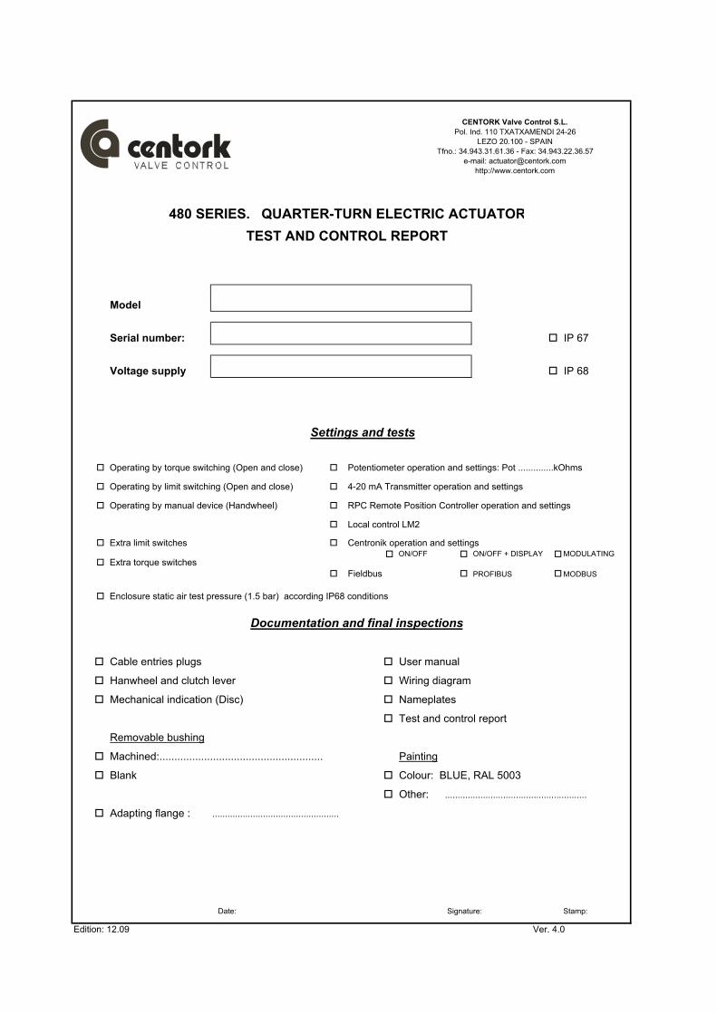
Model
Serial number: IP 67
Voltage supply IP 68
Operating by torque switching (Open and close) Potentiometer operation and settings: Pot ..............kOhms
Operating by limit switching (Open and close) 4-20 mA Transmitter operation and settings
Operating by manual device (Handwheel) RPC Remote Position Controller operation and settings
Local control LM2
Extra limit switches Centronik operation and settings
Extra torque switchesON/OFF MODULATING
Fieldbus MODBUS
Enclosure static air test pressure (1.5 bar) according IP68 conditions
Cable entries plugs User manual
Hanwheel and clutch lever Wiring diagram
Mechanical indication (Disc) Nameplates
Test and control report
Removable bushing
Machined:....................................................... Painting
Blank Colour: BLUE, RAL 5003
Other:
Adapting flange : ..................................................
Date: Signature: Stamp:
Edition: 12.09 Ver. 4.0
........................................................
TEST AND CONTROL REPORT
Documentation and final inspections
Settings and tests
480 SERIES. QUARTER-TURN ELECTRIC ACTUATOR
ON/OFF + DISPLAY
PROFIBUS
CENTORK Valve Control S.L.Pol. Ind. 110 TXATXAMENDI 24-26
LEZO 20.100 - SPAINTfno.: 34.943.31.61.36 - Fax: 34.943.22.36.57
e-mail: [email protected]://www.centork.com

CENTORK Valve Control S.L.
POL IND. 110, Txatxamendi 24-26 20.100 LEZO (SPAIN) Telf.: +34.943.31.61.37 Fax:: +34.943.22.36.57
Email: [email protected] http://www.centork.com
1497.MANE1480BPROX001 Edition: 08.10