Embed Size (px)
Citation preview
Operating Manual
CENTRA HS Digital Finishing System
Congratulations on your new purchase!

ii Location
Thank You for Selecting an Allen Datagraph Product
At Allen Datagraph Systems, Inc. (ADSI), we are committed to serving you, our customer. Our goal is to provide you with competitive, quality products and services to meet your needs. Customer input is of great value to Allen Datagraph Systems, Inc.; therefore, we encourage any comments or suggestions.
The instructions contained in this manual are intended to ensure the safe installation, operation, and maintenance of your machine. Please read this manual carefully before performing any activity on the equipment. Please note information contained in this manual does not modify or alter, in any way, the standard terms, and conditions of your Allen Datagraph Systems, Inc. purchase contract.
This manual should be readily accessible to operating and maintenance personnel at all times. Proper use of this manual, in addition to other Original Equipment Manufacturer’s manuals and your in-house manuals, will assure safe, reliable and cost-effective performance of ADSI machinery.
If you are in need of service, please contact our Technical Support staff as instructed on the following pages. In order to expedite your request please include the serial number of your machine. Each Allen Datagraph Systems, Inc. machine has a label identifying its serial number.
General Information
Allen Datagraph Systems, Inc. (Hereafter known as ADSI) Operating Manuals and Addenda provide a general understanding of the operation of the contracted system, its major components, and the functional elements of those components.
The Manuals and Addenda contain Safety, Description, Installation, Operation, and Maintenance information. We strongly recommend thoroughly reading and understanding the information in this manual before operating this equipment. If additional information is required, or clarification needed, feel free to contact ADSI.
The Manuals and Addenda may not be copied or reproduced, in whole or part, without written consent of Allen Datagraph Systems, Inc.

iii
Disclaimer of Warranties and Limitation of Liabilities
ADSI Digital Finishing Systems are warranted free of defects in both materials and workmanship. Should any part of this equipment be defective, it will be repaired or replaced, at the option of the manufacturer, at no charge for parts or factory labor for a period of one (1) year from the date of installation. All warranty services are performed at the ADSI factory. Replacement parts not installed at the factory will be billed to the customer at regular prices and credit will be issued when the defective parts are returned. The customer is responsible for freight on warranty parts and repairs.
This warranty is void if:
The equipment has been damaged by negligence, accident or mishandling, or has not been operated in accordance with the procedures described in the operating instructions;
or:
The equipment has been altered or repaired by other than an approved service station or factory service center, or adaptations or accessories have been attached to the equipment that shall have adversely affected the performance, safety, or reliability of the equipment.
NO OTHER WARRANTY, EXPRESSED OR IMPLIED, APPLIES to the equipment. ADSI does not assume any responsibility for consequential damages occasioned by the equipment, or inconvenience or interruption in operation.
In case of unsatisfactory operation, ADSI or its Dealer should be notified immediately.
Technical Support
Technical support is available during business hours based on Eastern Time Monday through Friday 8 am to 5 pm.
For Technical support click here to access our free e-mail support or visit our web site at http://www.allendatagraph.com.
Service Policy – All service is subject to ADSI service policy. You can read the policy here: Web Site Copy / CD Copy
There are many online documents available to help you to operate the CENTRA HS at our technical support page at http://www.allendatagraph.com. Click on Technical Support then Online Documents, fill out the form, and then click on the CENTRA link under the orange Label Production heading.
iv Location
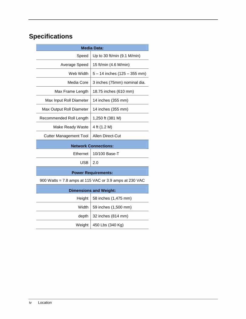
Specifications
Media Data:
Speed Up to 30 ft/min (9.1 M/min)
Average Speed 15 ft/min (4.6 M/min)
Web Width 5 – 14 inches (125 – 355 mm)
Media Core 3 inches (75mm) nominal dia.
Max Frame Length 18.75 inches (610 mm)
Max Input Roll Diameter 14 inches (355 mm)
Max Output Roll Diameter 14 inches (355 mm)
Recommended Roll Length 1,250 ft (381 M)
Make Ready Waste 4 ft (1.2 M)
Cutter Management Tool Allen Direct-Cut
Network Connections:
Ethernet 10/100 Base-T
USB 2.0
Power Requirements:
900 Watts = 7.8 amps at 115 VAC or 3.9 amps at 230 VAC
Dimensions and Weight:
Height 58 inches (1,475 mm)
Width 59 inches (1,500 mm)
depth 32 inches (814 mm)
Weight 450 Lbs (340 Kg)

v
Items Shipped Unassembled from Machine
A packing box marked “Accessories” is shipped with the equipment in the crate. These items are required for operating the equipment. The tools included in this kit (such as the Hex Key Wrenches) are specifically sized for the machine and should be stored nearby for easy access. The box contains the following items:
Accessory Kit
Component ID Description Qty
40239063 AC Power Cord, European Style 1
H05-353 Ethernet Crossover Adapter 1
H05-361 Black CAT 5E Ethernet Patch Cable, 14ft 1
H05-360 USB Cable, 10ft Grey (A Male to B Male) 1
PL-00-02-865 Knife Holder Assembly 1
H20-017 KNIFE BLADE, 30 DEGREES (Blue Tip) 1
H20-007 KNIFE BLADE,45 DEGREES (Red Tip) 1
H20-008 KNIFE BLADE,60 DEGREES (Green Tip) 1
H20-013 Black Fiber Tip Pen 1
H21-010 Hex Key Wrench, 3/32`` 1
H21-021 Hex Key Wrench, 3.0mm (Short Arm) 1
H21-022 Hex Key Wrench, 2.0mm (Short Arm) 1
H21-023 Hex Key Wrench, 1.5mm (Short Arm) 1
H21-024 Hex Key Wrench, 4.0mm (Short Arm) 1
LS-179 Long Hex Key Wrench, 7/64`` 1
DF-00-02-121 DFS T-Handle Wrench 1
PL-05-03-604 ADSI Firmware / Software CD 1
DT-413 Cut Strip Removal Tool 1
F-045 5A GMA Fuse, Normal Blow 2
F-054 2.5 Amp Metric Fuse, Slo-Blo 2
CN-053 Weed Bar O-Ring, 9/16" 6

vi Location
Table of Contents
Introduction ............................................................................................................ 1
Safety ...................................................................................................................... 1
Receiving and Inspecting the Equipment ............................................................ 2
Site Preparation ...................................................................................................... 3
Location ........................................................................................................................... 3 Power Requirements ....................................................................................................... 3
Power Configuration ..................................................................................................... 3 Changing the Fuse Configuration ................................................................................. 4
Unpacking and Installing the CENTRA HS Finisher ............................................ 5
Power Connection ........................................................................................................... 9
Software / Firmware Installation ........................................................................... 9
Items Needed .................................................................................................................. 9 Connect HS to Local Network ........................................................................................ 10 Configure the CENTRA HS Touch Panel Computer ...................................................... 10 Install Driver .................................................................................................................. 10 Software Updates .......................................................................................................... 13
Part and Accessory Identification ....................................................................... 14
Touch Panel Computer .................................................................................................. 15 Mandrels........................................................................................................................ 15 Idler Rollers and Hub Guides ......................................................................................... 15 Dancer Arms ................................................................................................................. 17 Laminator ...................................................................................................................... 18 Infeed and Outfeed Nip Stations .................................................................................... 19 Roll Handles .................................................................................................................. 19 Cut Station ..................................................................................................................... 20
Knife Holder Assembly ............................................................................................... 21 Cut Strip ..................................................................................................................... 21
Accumulator .................................................................................................................. 22 Weed Bar, Weed Brush, and Matrix Mandrel ................................................................. 23 Slitter Station ................................................................................................................. 24 Take-Up Mandrels ......................................................................................................... 24
Webbing the System ............................................................................................ 25
Prepare the Finisher for Webbing and Test Cut ............................................................. 25 Load Mandrels, Set Guides, and Set Accumulators .................................................... 25 Install Cutting Knife .................................................................................................... 26 Knife Blade Depth Adjustment .................................................................................... 27
Web the Finisher Input Section ...................................................................................... 28 Web Laminate Material .............................................................................................. 29
Web the Finisher Accumulators and Cutter .................................................................... 30 Web the Outfeed Nip and Slitter .................................................................................... 32 Web the Matrix Mandrel and its Dancer Arm ................................................................. 32 Finish Webbing .............................................................................................................. 33

vii
Set Cutting Function ............................................................................................ 34
Make a Test Cut ............................................................................................................ 34 Knife Blade Depth Adjustment .................................................................................... 35
Align Sensor to Registration Mark ................................................................................. 36
Operating the CENTRA HS .................................................................................. 37
Start Up ......................................................................................................................... 37 Run ................................................................................................................................ 37
Mandrel Dancer Tension Adjustment.......................................................................... 37 Shut Down ..................................................................................................................... 38 Using the Control Panel Program .................................................................................. 39 Home Screen ................................................................................................................ 39 Controls Screen ............................................................................................................. 40
Main Cutter Controls .................................................................................................. 40 Cutting Knife Controls ................................................................................................ 41 Nip Controls ............................................................................................................... 41 Motor Controls ............................................................................................................ 41 Joystick Controls ........................................................................................................ 42
Previous Screen ............................................................................................................ 43 Exit Program .................................................................................................................. 43 Using Accessories ......................................................................................................... 44
Weed Bar ................................................................................................................... 44 Weed Brush ............................................................................................................... 45
Maintenance & Consumables ............................................................................. 47
Fuses ............................................................................................................................ 47 Replacing a Fuse ....................................................................................................... 47
Cutting Blades ............................................................................................................... 48 Changing a Knife Blade .............................................................................................. 48 Cleaning Cutting Blades ............................................................................................. 49
Changing a Cut Strip ..................................................................................................... 50 Cleaning the CENTRA HS Finisher ............................................................................... 51
Biweekly Cleaning ...................................................................................................... 51 Monthly Cleaning........................................................................................................ 52 Annual Cleaning ......................................................................................................... 52 Pinch Wheel Maintenance .......................................................................................... 53
Belt Adjustments ............................................................................................................ 54 Verify Belt Tension ..................................................................................................... 54 Mandrel Drive Belt Tensioning.................................................................................... 54 Nip Roller Drive Belt ................................................................................................... 55 Adjust Carriage (Y-Axis) Drive Belt Tension ............................................................... 56 Adjust Grit Wheel (X-Axis) Drive Belt Tension ............................................................ 57 Adjust Long Carriage Belt Tension ............................................................................. 58

viii Location
APPENDIX A - Operating File Creation .................................................................. 60
Explanation of SmartMarkTM .......................................................................................... 60 Registration Mark Placement and File Creation ............................................................. 60
Skew and Scale Registration Marks ........................................................................... 62 Creating the “Cut” File for the Finisher ........................................................................... 64
Creating Plot File with Adobe Illustrator ...................................................................... 64 Creating Plot File with CorelDraw ............................................................................... 64
Allen DirectCut Document Options ................................................................................ 65 Find Origin.................................................................................................................. 65 Sort Method ................................................................................................................ 65 Rotation ...................................................................................................................... 65 Space between jobs ................................................................................................... 66
APPENDIX B - Changing Units of Measure ............................................................ 67
Instructions for Windows XP and Vista OS .................................................................... 67
APPENDIX C - Troubleshooting i-TECH CENTRA HS Finisher ............................ 69
APPENDIX D - Connect HS to Local Network ........................................................ 73
Using Two Wall Jacks.................................................................................................... 73 Using One Wall Jack ..................................................................................................... 73 Using a Crossover Cable ............................................................................................... 73
APPENDIX E - Radio and Television Interference ................................................. 76
APPENDIX F - Advanced Menus and Control Panel Options ............................... 77
Changing Menu Mode ................................................................................................... 77 Changing Control Panel Starting Defaults...................................................................... 77 Setting Joystick Parameters .......................................................................................... 78 Adjusting Sensor Offsets and Size Using the SmartMark Sensor Menu ........................ 79
Sensor Offsets ........................................................................................................... 79 X/Y Sensor size .......................................................................................................... 80
Calibration ..................................................................................................................... 82 XY Motor Calibration .................................................................................................. 82 Calibrate To Printer .................................................................................................... 84 Default Calibration (Customer Diagnostic Menu) ........................................................ 85
Action ............................................................................................................................ 86 Save / Restore Settings from Cutter to File................................................................. 86 Save / Restore Calibration .......................................................................................... 87
Settings Menu ............................................................................................................... 87 Knife Offset ................................................................................................................ 88 Minimum Angle .......................................................................................................... 89
XY Motor Menu.............................................................................................................. 89 Main Menu ..................................................................................................................... 91
Last Error ................................................................................................................... 91
APPENDIX G - Codes ............................................................................................ 92
MMC Error Codes .......................................................................................................... 92 Boot Up / Self-test Codes .............................................................................................. 96

Introduction
1
Introduction
The CENTRA HS Finishing System is shipped fully assembled however, it must be properly unpacked, installed, and setup to run prior to operating. This manual will guide you through each of these processes.
Safety
For your own safety, read this instruction manual before operating the equipment.
Knowledge of the machine’s components and specific hazards will minimize the possibility of accidents and injury.
Wear proper clothing. Do not wear loose clothing, neckties, necklaces, or jewelry, which may be caught in moving parts. Shoulder length hair and longer should be pulled back, and secured at all times to prevent catching in equipment.
Keep your work area clean and well lit to prevent tripping or accidently placing arms, hands, and fingers in danger.
An Emergency Stop push button located on the front of the machine near the cutter. Do not use the E-stop to power off equipment unless there is an emergency.
The E-Stop only powers off the system equipment. It does not power off the Control Panel computer.
Figure 1: E-Stop Location

Receiving and Inspecting the Equipment
2 Location
Receiving and Inspecting the Equipment
Inspect the ADSI equipment immediately upon arrival at the installation site as follows:
Note any visual in-transit damage to the packing crate or the equipment on the carrier's delivery slip.
Report any concealed in-transit damage to the delivery carrier and to ADSI as soon as it is discovered. When possible, take pictures for claim purposes.
Cross-reference amounts received to amounts shipped as indicated on the packing lists forwarded with the machinery. Report shortages and/or defective material immediately to ADSI customer service office.
ADSI may require defective components to be returned in order to issue credit under warranty. Do not return any items without first contacting ADSI and obtaining a Return Authorization.

Site Preparation
3
Site Preparation
The following are guidelines for preparing the customer site for installation of the ADSI equipment.
Location
1. Provide a sturdy level surface for heavy equipment.
2. Provide adequate clearance around the machine to allow easy access for inspection and maintenance.
3. Ensure there is an appropriate power source nearby.
Power Requirements
Use of a HIGH QUALITY surge protector or uninterruptible power supply is REQUIRED by ADSI. Failure to do so could affect your warranty coverage if a problem arises due to improper power connection!
Risk of Electric Shock
The power cord is a three-conductor cable that uses a safety (earth) ground connection. The power cord must be plugged into an outlet that has an earth ground contact.
NEVER plug the power cord into a two-prong outlet by using a 3=2 cord adapter.
Risk of Electrical Fire
NEVER allow roll or sheet goods to rub on the power cord as the material may damage the cord causing an electrical fire hazard!
Power Configuration
ADSI products are factory preset for the power requirements of the destination country. The machine configuration is indicated on the power input module as either 115V or 230V.
Site Preparation
4 Power Requirements
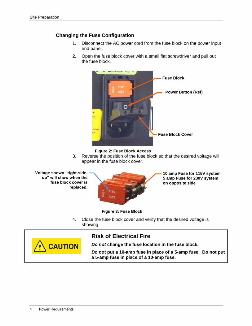
Changing the Fuse Configuration
1. Disconnect the AC power cord from the fuse block on the power input end panel.
2. Open the fuse block cover with a small flat screwdriver and pull out the fuse block.
3. Reverse the position of the fuse block so that the desired voltage will appear in the fuse block cover.
4. Close the fuse block cover and verify that the desired voltage is showing.
Risk of Electrical Fire
Do not change the fuse location in the fuse block.
Do not put a 10-amp fuse in place of a 5-amp fuse. Do not put a 5-amp fuse in place of a 10-amp fuse.
Figure 2: Fuse Block Access
Power Button (Ref)
Fuse Block Cover
Fuse Block
Figure 3: Fuse Block
Voltage shown “right-side-up” will show when the
fuse block cover is
replaced.
10 amp Fuse for 115V system 5 amp Fuse for 230V system
on opposite side
Unpacking and Installing the CENTRA HS Finisher
Power Requirements 5
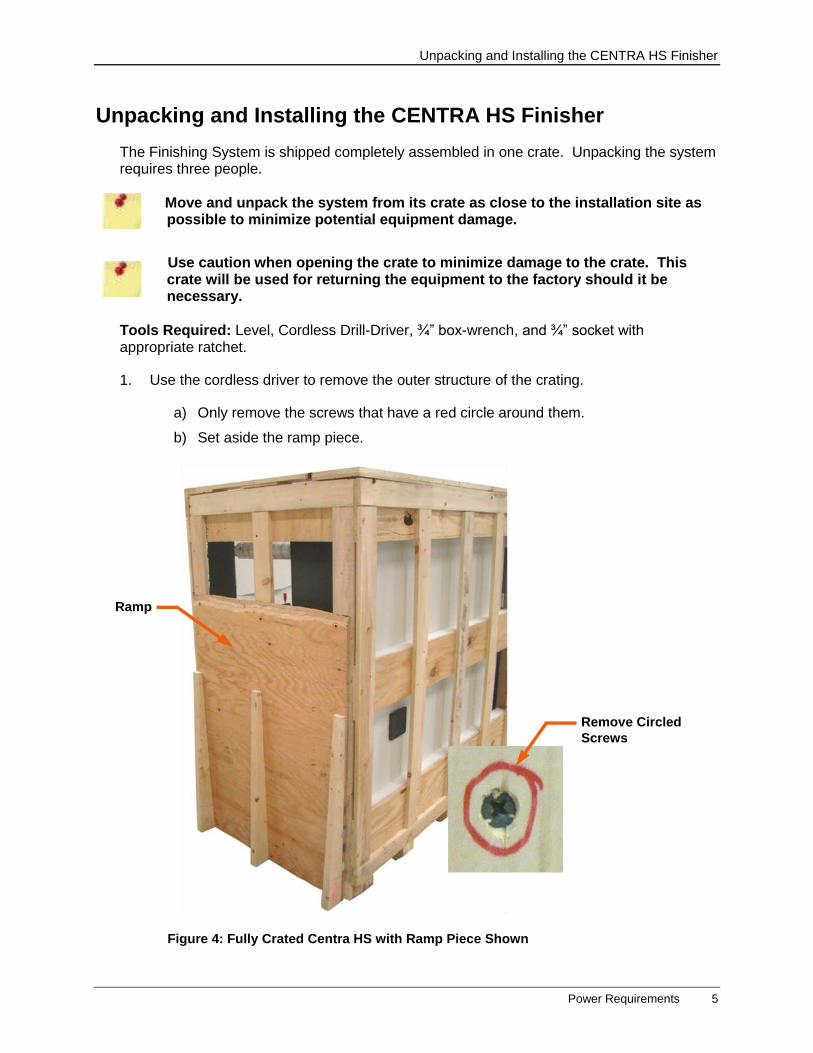
Unpacking and Installing the CENTRA HS Finisher
The Finishing System is shipped completely assembled in one crate. Unpacking the system requires three people.
Move and unpack the system from its crate as close to the installation site as possible to minimize potential equipment damage.
Use caution when opening the crate to minimize damage to the crate. This crate will be used for returning the equipment to the factory should it be necessary.
Tools Required: Level, Cordless Drill-Driver, ¾” box-wrench, and ¾” socket with appropriate ratchet.
1. Use the cordless driver to remove the outer structure of the crating.
a) Only remove the screws that have a red circle around them.
b) Set aside the ramp piece.
Figure 4: Fully Crated Centra HS with Ramp Piece Shown
Ramp
Remove Circled
Screws
Unpacking and Installing the CENTRA HS Finisher
6 Power Requirements
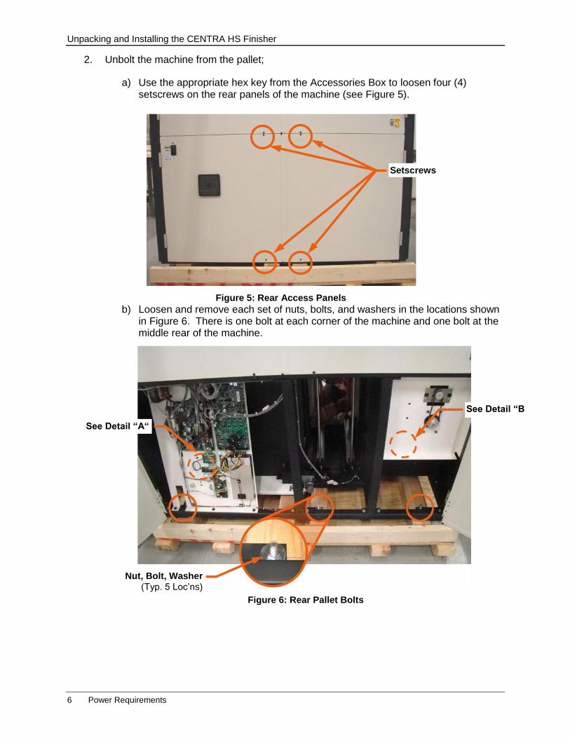
2. Unbolt the machine from the pallet;
a) Use the appropriate hex key from the Accessories Box to loosen four (4) setscrews on the rear panels of the machine (see Figure 5).
b) Loosen and remove each set of nuts, bolts, and washers in the locations shown in Figure 6. There is one bolt at each corner of the machine and one bolt at the middle rear of the machine.
Figure 6: Rear Pallet Bolts
Nut, Bolt, Washer (Typ. 5 Loc’ns)
See Detail “B “
See Detail “A“
Figure 5: Rear Access Panels
Setscrews

Unpacking and Installing the CENTRA HS Finisher
Power Requirements 7
Details “A” and “B” (below) show the location and access of the bolts near the front of the machine.
3. Remove 4 x 4 supports from the underside of the machine as follows;
a) Using the built-in ratchets (see Figure 7), lower the support feet down so that the machine wheels lift off the 4x4 supports.
Detail B
Access the bolt at the discharge end by opening the panel to
the storage area.
Figure 7: Ratcheting Foot
Pull Ratchet Handle out
using attached ring.
Engage Pawl on this
side to lower feet
This bolt may be accessed by reaching through the accumulator opening at the front of the machine; or by removing the front panel closest to its location.
Detail A
Unpacking and Installing the CENTRA HS Finisher
8 Power Requirements
b) Slide the 4x4 supports out from under the machine.
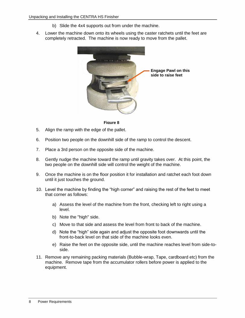
4. Lower the machine down onto its wheels using the caster ratchets until the feet are completely retracted. The machine is now ready to move from the pallet.
5. Align the ramp with the edge of the pallet.
6. Position two people on the downhill side of the ramp to control the descent.
7. Place a 3rd person on the opposite side of the machine.
8. Gently nudge the machine toward the ramp until gravity takes over. At this point, the two people on the downhill side will control the weight of the machine.
9. Once the machine is on the floor position it for installation and ratchet each foot down until it just touches the ground.
10. Level the machine by finding the “high corner” and raising the rest of the feet to meet that corner as follows:
a) Assess the level of the machine from the front, checking left to right using a level.
b) Note the "high" side.
c) Move to that side and assess the level from front to back of the machine.
d) Note the “high” side again and adjust the opposite foot downwards until the front-to-back level on that side of the machine looks even.
e) Raise the feet on the opposite side, until the machine reaches level from side-to-side.
11. Remove any remaining packing materials (Bubble-wrap, Tape, cardboard etc) from the machine. Remove tape from the accumulator rollers before power is applied to the equipment.
Figure 8
Engage Pawl on this side to raise feet

Software / Firmware Installation
Items Needed 9
Power Connection
Connect the power supply cable to the power port on the left side of the machine and to your surge protector or UPS (as noted in Site Preparation).
Software / Firmware Installation
Items Needed
PC (Customer Supplied) with Adobe Illustrator or Corel Draw installed on it.
Shared folder on network for artwork files (recommended).
Internet access available at all times to assist troubleshooting (recommended).
Phone near computer (recommended).
Web Cam (recommended) for remote training from ADSI.
USB or Ethernet connection to computer (when prompted)
ADSI Installation CD-Rom
USB Mouse (optional)
Risk of Electrical Equipment Damage
Running this machine on 230V power with Power Port fuse set for 115V will cause damage to the equipment.
Verify that the voltage showing through the fuse block window is the same as the supply line voltage.
Figure 9: Power Port
Power Switch
Fuse Block
(ref)
Power Cable
Conn.

Software / Firmware Installation
10 Install Driver
Connect HS to Local Network
1. Connect an Ethernet cable from the HS to the computer or to the local network. Follow the instructions in “APPENDIX D - Connect HS to Local Network” if you do not have an IT professional that can help you.
2. Verify power input matches the fuse showing on the Power Port.
Configure the CENTRA HS Touch Panel Computer
1. Power on the finisher using the power switch on the rear of the machine.
2. Plug a USB mouse into the bottom of the control panel.
3. Power on the Control Panel by pressing its power button.
4. Log in and open the touch screen keyboard by pressing on the small tab on the upper right side of the touch screen.
5. Touch the name of the screen and click on exit to close the remote panel program that started automatically.
6. Connect the touch screen control panel computer to your network using standard Windows tools. If you do not know how to do this, ask your IT administrator.
7. Create a new user name or log into the network as an existing user.
8. Create a shared folder to store “cut files”.
9. Log off administrator and log on using new user.
10. Click on the “reload cache” button on the screen to load cutter variables into the registry.
11. Leave the machine powered on and connected to the network for the next step.
Install Driver
The ASDI installation CD contains Allen DirectCut software and the Cutter Driver used with it. This software should be installed on the customer supplied PC, not on the Control Panel computer. We suggest using the default locations that appear when the program is installed.
1. Insert the ADSI CD-Rom into the operating PC and follow prompts as follows:
If the CD does not auto start, open the file explorer, right click on the CD driver and select “auto play”.
Software / Firmware Installation
Install Driver 11
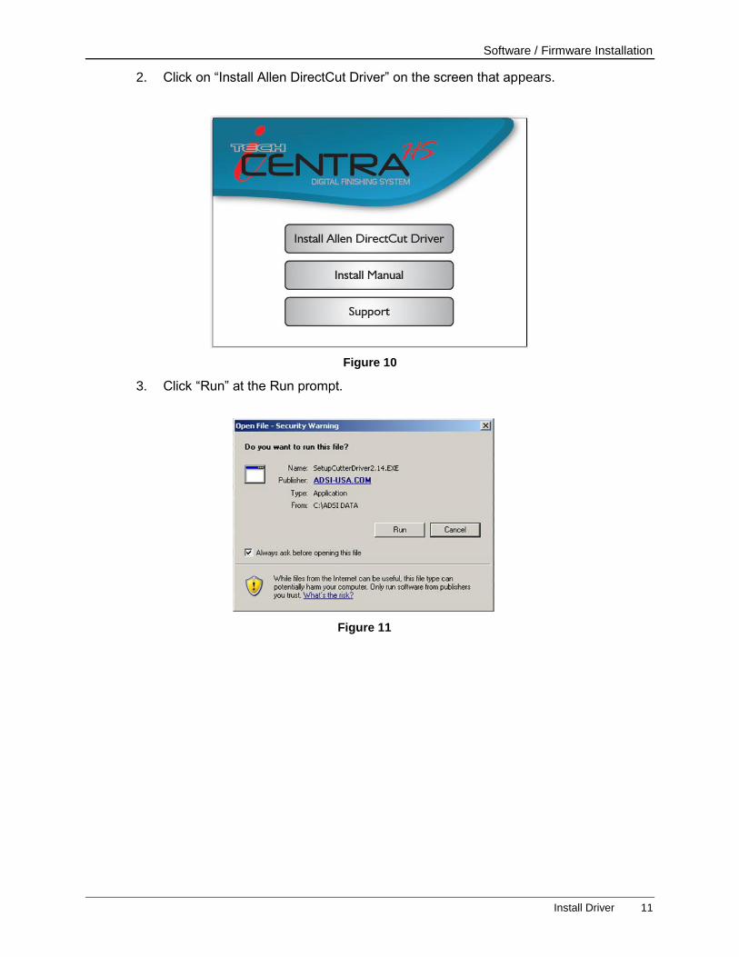
2. Click on “Install Allen DirectCut Driver” on the screen that appears.
3. Click “Run” at the Run prompt.
Figure 10
Figure 11
Software / Firmware Installation
12 Install Driver
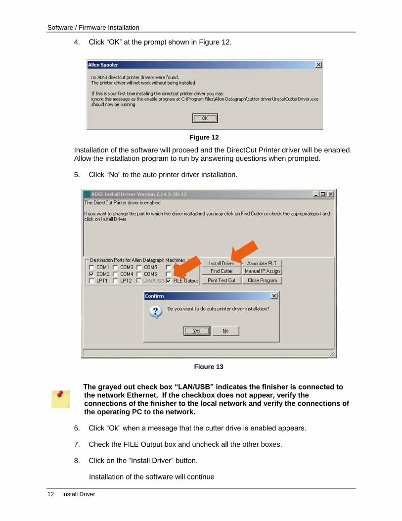
4. Click “OK” at the prompt shown in Figure 12.
Installation of the software will proceed and the DirectCut Printer driver will be enabled. Allow the installation program to run by answering questions when prompted.
5. Click “No” to the auto printer driver installation.
The grayed out check box “LAN/USB” indicates the finisher is connected to the network Ethernet. If the checkbox does not appear, verify the connections of the finisher to the local network and verify the connections of the operating PC to the network.
6. Click “Ok” when a message that the cutter drive is enabled appears.
7. Check the FILE Output box and uncheck all the other boxes.
8. Click on the “Install Driver” button.
Installation of the software will continue
Figure 13
LAN/USB
Figure 12
Software / Firmware Installation
Software Updates 13
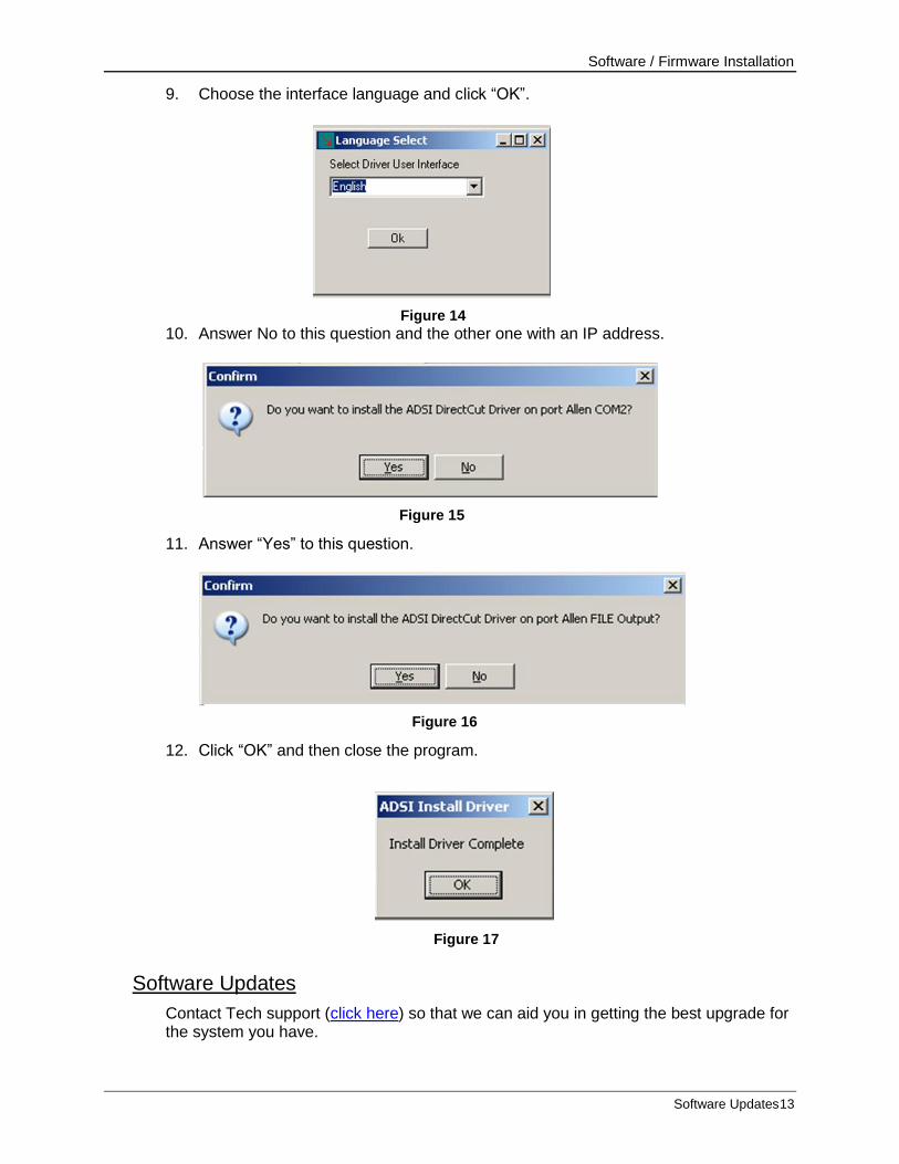
9. Choose the interface language and click “OK”.
10. Answer No to this question and the other one with an IP address.
11. Answer “Yes” to this question.
12. Click “OK” and then close the program.
Software Updates
Contact Tech support (click here) so that we can aid you in getting the best upgrade for the system you have.
Figure 14
Figure 17
Figure 16
Figure 15
Part and Accessory Identification
14 Software Updates
Part and Accessory Identification
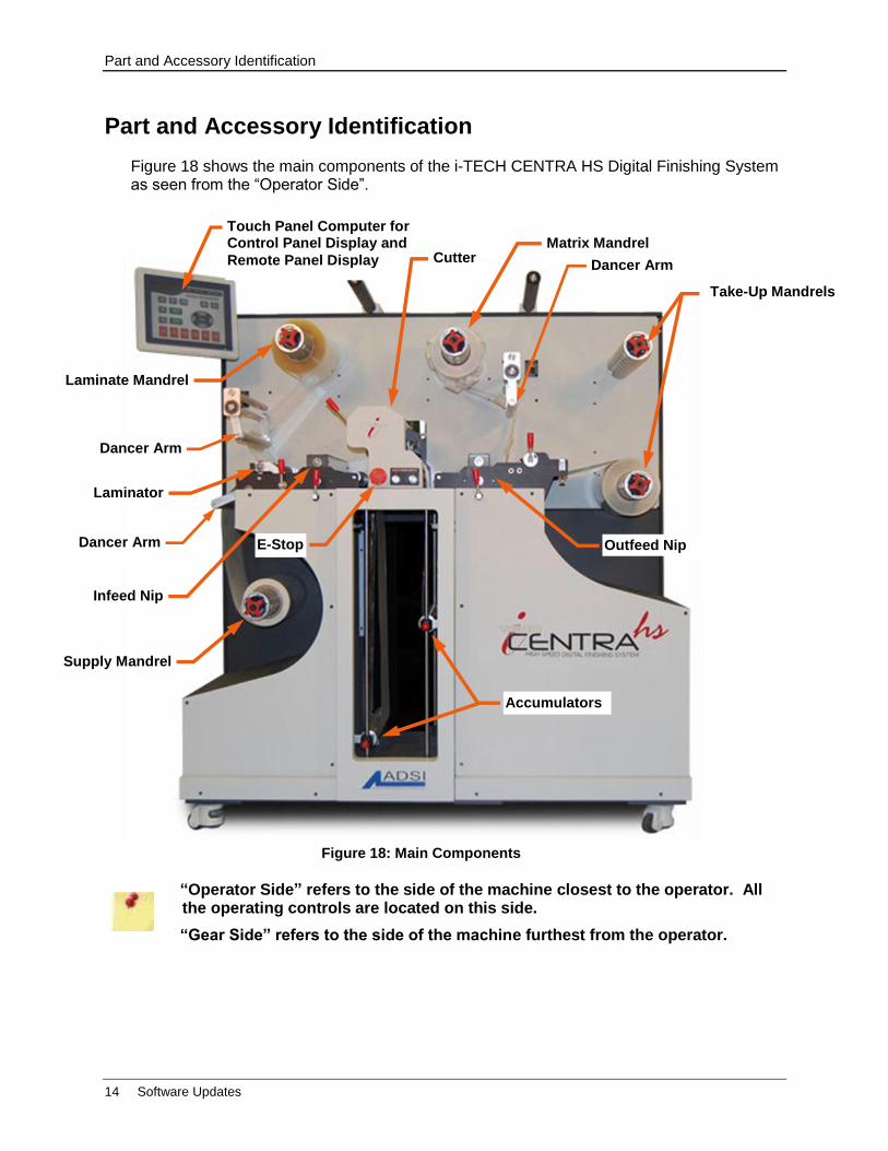
Figure 18 shows the main components of the i-TECH CENTRA HS Digital Finishing System as seen from the “Operator Side”.
“Operator Side” refers to the side of the machine closest to the operator. All the operating controls are located on this side.
“Gear Side” refers to the side of the machine furthest from the operator.
Figure 18: Main Components
Infeed Nip
Dancer Arm E-Stop
Touch Panel Computer for Control Panel Display and
Remote Panel Display
Laminate Mandrel
Cutter Matrix Mandrel
Supply Mandrel
Accumulators
Laminator
Outfeed Nip
Dancer Arm
Dancer Arm
Take-Up Mandrels
Part and Accessory Identification
Idler Rollers and Hub Guides 15
Touch Panel Computer
The Touch Panel Computer that comes with your ADSI CENTRA HS is operated using its touch screen interface. This panel provides access to the Control Panel Program and its menus. See “APPENDIX F - Advanced Menus and Control Panel Options”
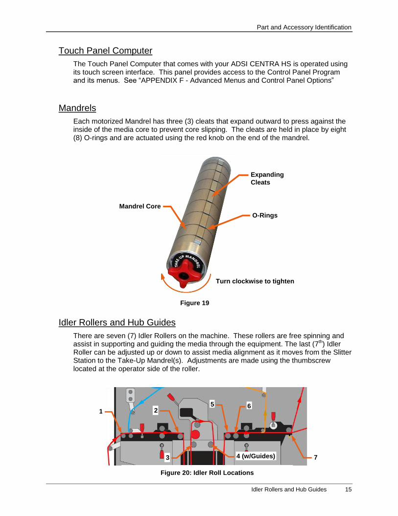
Mandrels
Each motorized Mandrel has three (3) cleats that expand outward to press against the inside of the media core to prevent core slipping. The cleats are held in place by eight (8) O-rings and are actuated using the red knob on the end of the mandrel.
Idler Rollers and Hub Guides
There are seven (7) Idler Rollers on the machine. These rollers are free spinning and assist in supporting and guiding the media through the equipment. The last (7th) Idler Roller can be adjusted up or down to assist media alignment as it moves from the Slitter Station to the Take-Up Mandrel(s). Adjustments are made using the thumbscrew located at the operator side of the roller.
Figure 20: Idler Roll Locations
1
3
5 2
4 (w/Guides)
6
7
Figure 19
Turn clockwise to tighten
Expanding
Cleats
Mandrel Core
O-Rings
Part and Accessory Identification
16 Idler Rollers and Hub Guides
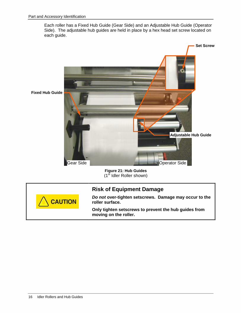
Each roller has a Fixed Hub Guide (Gear Side) and an Adjustable Hub Guide (Operator Side). The adjustable hub guides are held in place by a hex head set screw located on each guide.
Risk of Equipment Damage
Do not over-tighten setscrews. Damage may occur to the roller surface.
Only tighten setscrews to prevent the hub guides from moving on the roller.
Figure 21: Hub Guides
(1st Idler Roller shown)
Set Screw
Gear Side Operator Side
Adjustable Hub Guide
Fixed Hub Guide
Part and Accessory Identification
Dancer Arms 17
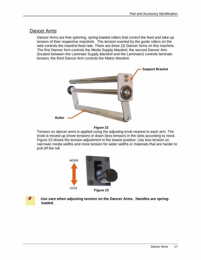
Dancer Arms
Dancer Arms are free spinning, spring-loaded rollers that control the feed and take-up tension of their respective mandrels. The tension exerted by the guide rollers on the web controls the mandrel feed rate. There are three (3) Dancer Arms on this machine. The first Dancer Arm controls the Media Supply Mandrel; the second Dancer Arm (located between the Laminate Supply Mandrel and the Laminator) controls laminate tension; the third Dancer Arm controls the Matrix Mandrel.
Tension on dancer arms is applied using the adjusting knob nearest to each arm. The knob is moved up (more tension) or down (less tension) in the slots according to need. Figure 23 shows the tension adjustment in the lowest position. Use less tension on narrower media widths and more tension for wider widths or materials that are harder to pull off the roll.
Use care when adjusting tension on the Dancer Arms. Handles are spring-loaded.
Figure 22
Roller
Support Bracket
Figure 23
MORE
LESS
Part and Accessory Identification
18 Laminator
Laminator
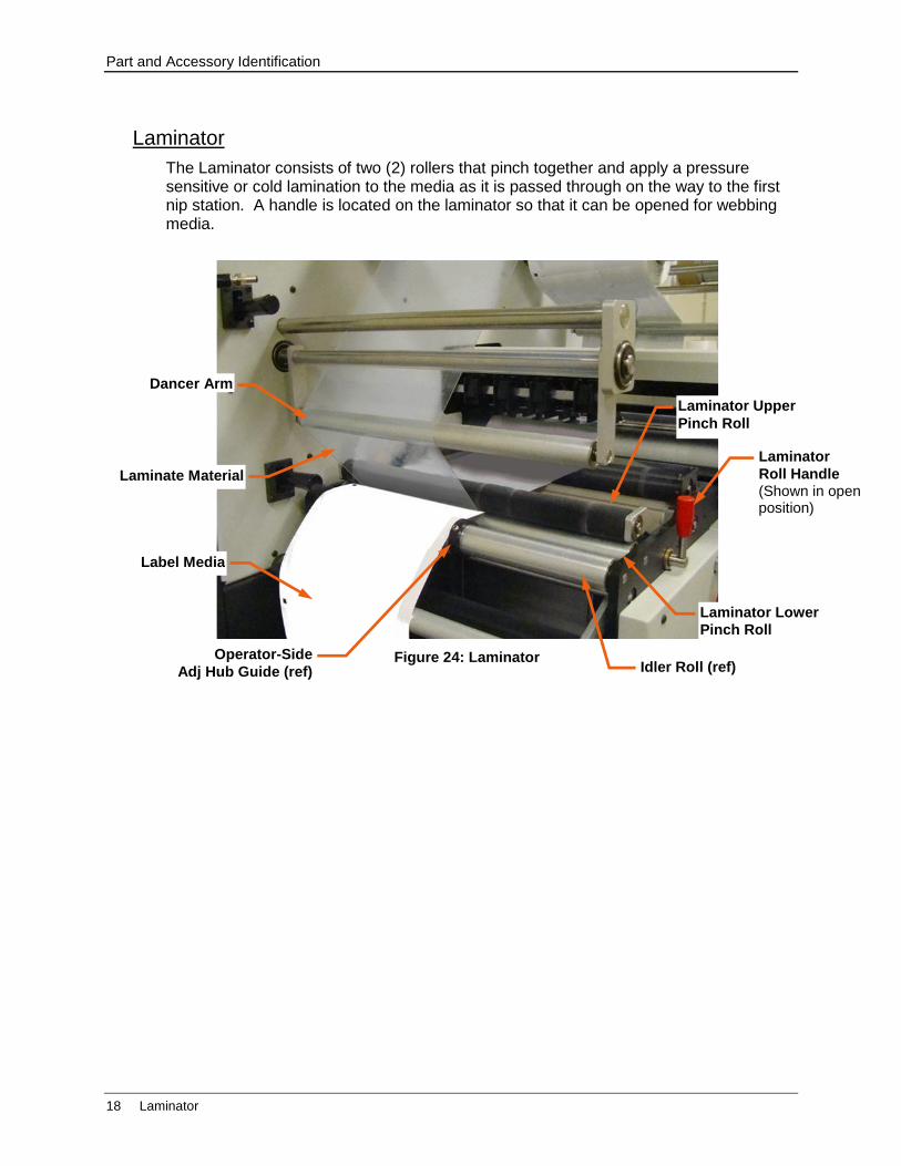
The Laminator consists of two (2) rollers that pinch together and apply a pressure sensitive or cold lamination to the media as it is passed through on the way to the first nip station. A handle is located on the laminator so that it can be opened for webbing media.
Figure 24: Laminator
Laminate Material
Label Media
Dancer Arm
Laminator
Roll Handle
Laminator Upper
Pinch Roll
Idler Roll (ref)
Laminator Lower
Pinch Roll
Operator-Side
Adj Hub Guide (ref)
(Shown in open position)
Part and Accessory Identification
Roll Handles 19
Infeed and Outfeed Nip Stations
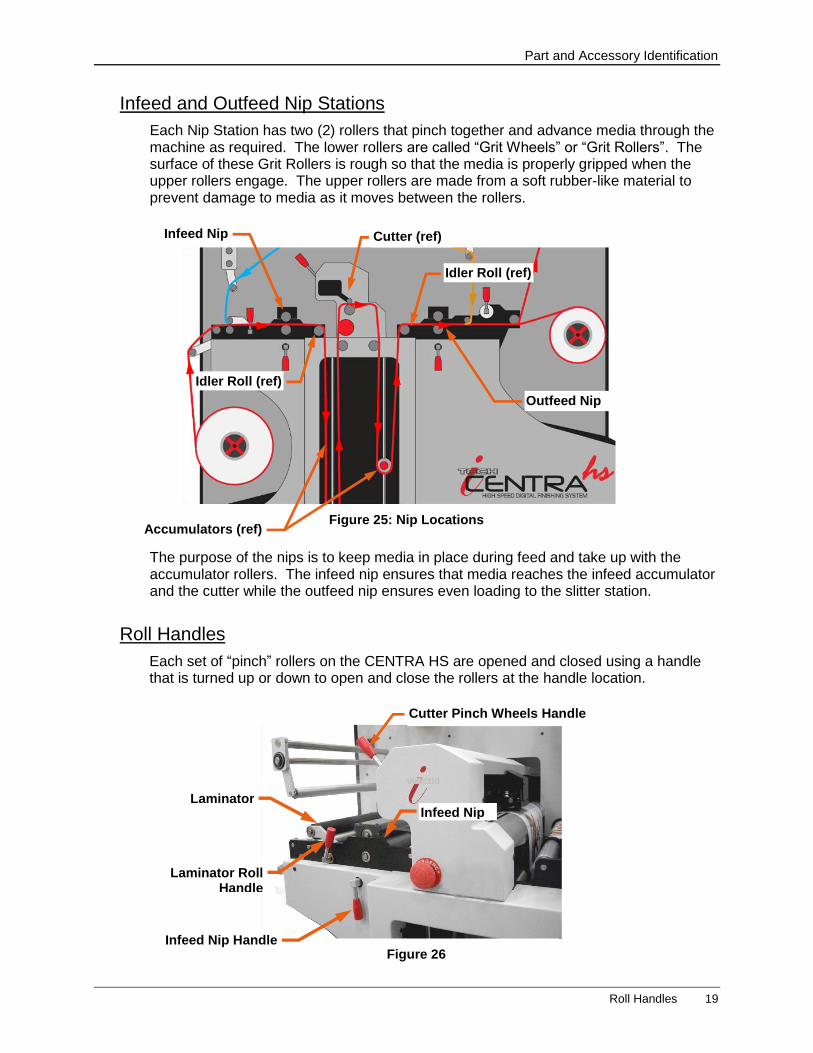
Each Nip Station has two (2) rollers that pinch together and advance media through the machine as required. The lower rollers are called “Grit Wheels” or “Grit Rollers”. The surface of these Grit Rollers is rough so that the media is properly gripped when the upper rollers engage. The upper rollers are made from a soft rubber-like material to prevent damage to media as it moves between the rollers.
The purpose of the nips is to keep media in place during feed and take up with the accumulator rollers. The infeed nip ensures that media reaches the infeed accumulator and the cutter while the outfeed nip ensures even loading to the slitter station.
Roll Handles
Each set of “pinch” rollers on the CENTRA HS are opened and closed using a handle that is turned up or down to open and close the rollers at the handle location.
Figure 25: Nip Locations
Infeed Nip
Outfeed Nip
Cutter (ref)
Idler Roll (ref)
Idler Roll (ref)
Accumulators (ref)
Figure 26
Cutter Pinch Wheels Handle
Infeed Nip
Infeed Nip Handle
Laminator Rolls
Laminator Roll Handle
Part and Accessory Identification
20 Cut Station
There is a handle for the Laminator rollers, the Infeed Nip, the Cutter Pinch Wheels, the Outfeed Nip and the Slitter.
Handles are used to open a gap between rollers during the webbing process or when fine-tuning web alignment.
Handle Down = Closed/Engaged – Handle Up = Open/Disengaged
Cut Station
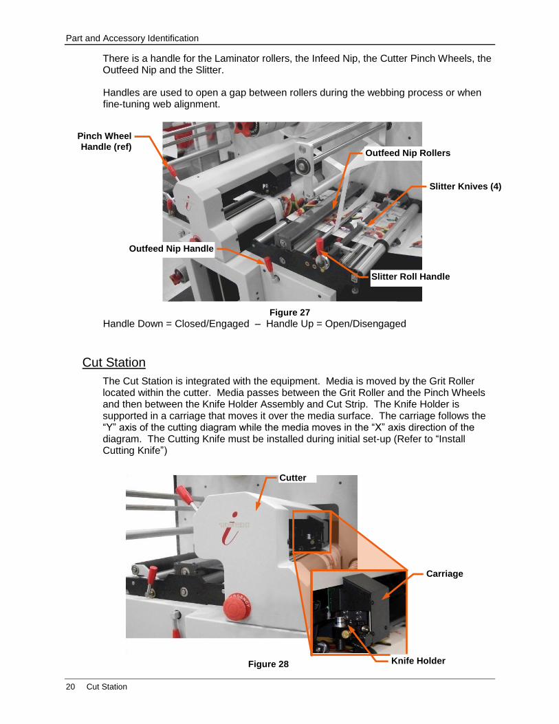
The Cut Station is integrated with the equipment. Media is moved by the Grit Roller located within the cutter. Media passes between the Grit Roller and the Pinch Wheels and then between the Knife Holder Assembly and Cut Strip. The Knife Holder is supported in a carriage that moves it over the media surface. The carriage follows the “Y” axis of the cutting diagram while the media moves in the “X” axis direction of the diagram. The Cutting Knife must be installed during initial set-up (Refer to “Install Cutting Knife”)
Figure 28
Carriage
Knife Holder
Cutter
Figure 27
Outfeed Nip Handle
Pinch Wheel
Handle (ref) Outfeed Nip Rollers
Slitter Knives (4)
Slitter Roll Handle
Part and Accessory Identification
Cut Station 21
Knife Holder Assembly
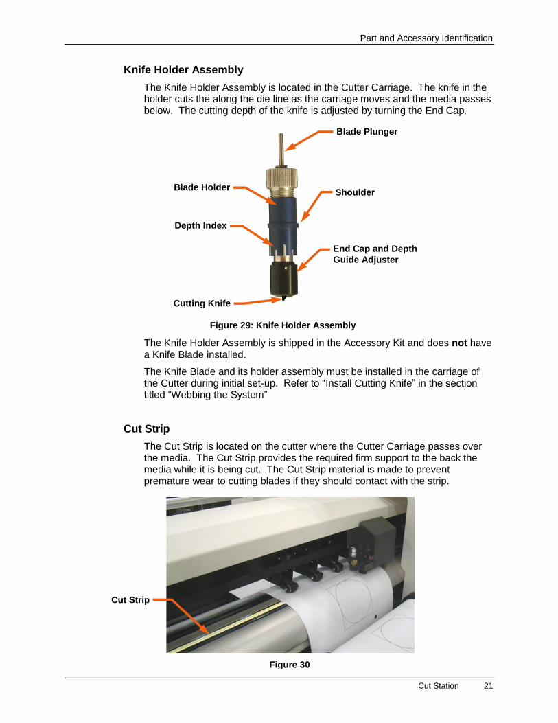
The Knife Holder Assembly is located in the Cutter Carriage. The knife in the holder cuts the along the die line as the carriage moves and the media passes below. The cutting depth of the knife is adjusted by turning the End Cap.
The Knife Holder Assembly is shipped in the Accessory Kit and does not have a Knife Blade installed.
The Knife Blade and its holder assembly must be installed in the carriage of the Cutter during initial set-up. Refer to “Install Cutting Knife” in the section titled “Webbing the System”
Cut Strip
The Cut Strip is located on the cutter where the Cutter Carriage passes over the media. The Cut Strip provides the required firm support to the back the media while it is being cut. The Cut Strip material is made to prevent premature wear to cutting blades if they should contact with the strip.
Figure 29: Knife Holder Assembly
End Cap and Depth
Guide Adjuster
Blade Holder Shoulder
Blade Plunger
Depth Index
Cutting Knife
Figure 30
Cut Strip
Part and Accessory Identification
22 Accumulator
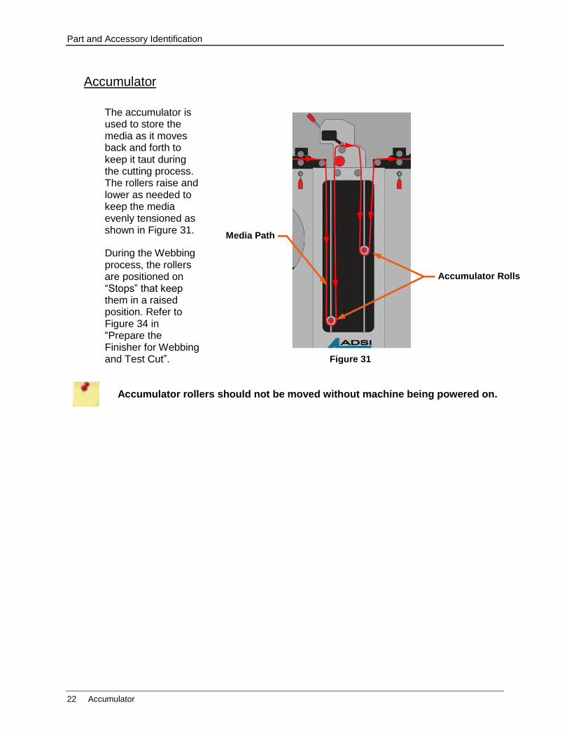
Accumulator
The accumulator is used to store the media as it moves back and forth to keep it taut during the cutting process. The rollers raise and lower as needed to keep the media evenly tensioned as shown in Figure 31.
During the Webbing process, the rollers are positioned on “Stops” that keep them in a raised position. Refer to Figure 34 in “Prepare the Finisher for Webbing and Test Cut”.
Accumulator rollers should not be moved without machine being powered on.
Figure 31
Media Path
Accumulator Rolls
Part and Accessory Identification
Weed Bar, Weed Brush, and Matrix Mandrel 23
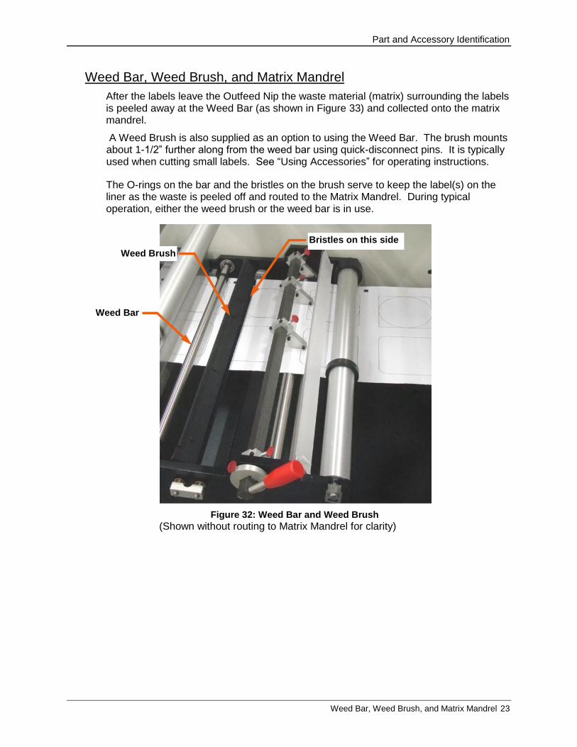
Weed Bar, Weed Brush, and Matrix Mandrel
After the labels leave the Outfeed Nip the waste material (matrix) surrounding the labels is peeled away at the Weed Bar (as shown in Figure 33) and collected onto the matrix mandrel.
A Weed Brush is also supplied as an option to using the Weed Bar. The brush mounts about 1-1/2” further along from the weed bar using quick-disconnect pins. It is typically used when cutting small labels. See “Using Accessories” for operating instructions.
The O-rings on the bar and the bristles on the brush serve to keep the label(s) on the liner as the waste is peeled off and routed to the Matrix Mandrel. During typical operation, either the weed brush or the weed bar is in use.
Figure 32: Weed Bar and Weed Brush
(Shown without routing to Matrix Mandrel for clarity)
Weed Bar
Weed Brush
Bristles on this side
Part and Accessory Identification
24 Take-Up Mandrels
Slitter Station
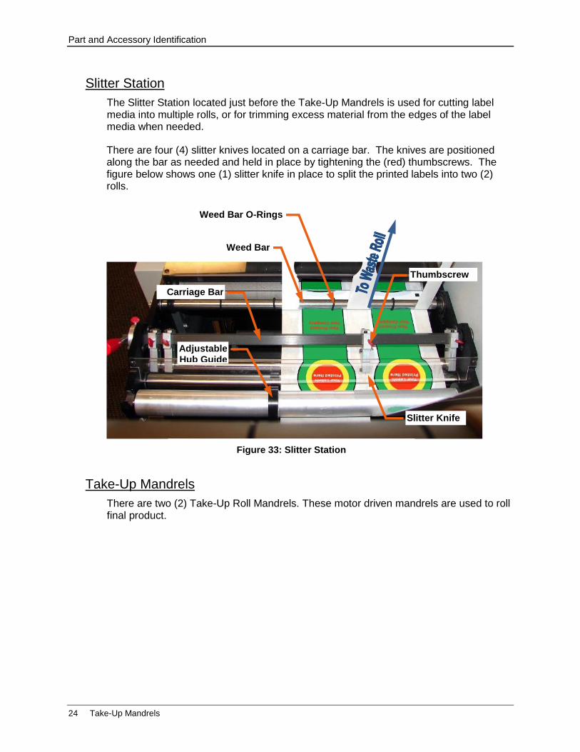
The Slitter Station located just before the Take-Up Mandrels is used for cutting label media into multiple rolls, or for trimming excess material from the edges of the label media when needed.
There are four (4) slitter knives located on a carriage bar. The knives are positioned along the bar as needed and held in place by tightening the (red) thumbscrews. The figure below shows one (1) slitter knife in place to split the printed labels into two (2) rolls.
Take-Up Mandrels
There are two (2) Take-Up Roll Mandrels. These motor driven mandrels are used to roll final product.
Figure 33: Slitter Station
Weed Bar
Carriage Bar
Slitter Knife
Thumbscrew
Weed Bar O-Rings
Adjustable Hub Guide
Webbing the System
Prepare the Finisher for Webbing and Test Cut 25
Webbing the System
The CENTRA HS Finisher can be set up to laminate and then cut labels. To use the optional laminating function, add a roll of laminate material when “webbing” the system with the label media.
The power to the HS must be ON during webbing of material. Do not move Accumulator rollers unless the machine is powered on.
Prepare the Finisher for Webbing and Test Cut
1. Power on the Finisher and the Control Panel.
2. Set the Motors Mode to “Off” to keep mandrels and nips from turning.
Load Mandrels, Set Guides, and Set Accumulators
1. Ensure mandrel cleats are not expanded before loading media or roll cores.
2. Loosen the adjustable hub guides (operator side only) on the finisher.
a) Use the supplied T-Handle Wrench to loosen the setscrews.
b) Slide the hub guides out so that they will not be in the way during the webbing process.
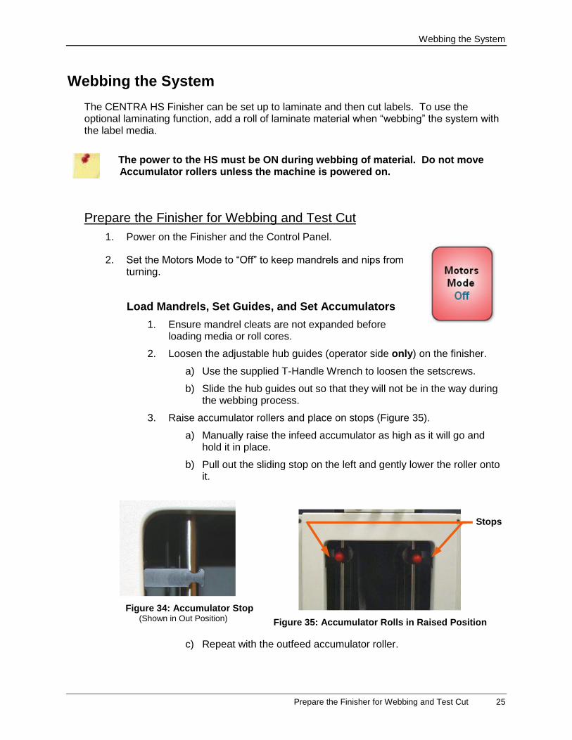
3. Raise accumulator rollers and place on stops (Figure 35).
a) Manually raise the infeed accumulator as high as it will go and hold it in place.
b) Pull out the sliding stop on the left and gently lower the roller onto it.
c) Repeat with the outfeed accumulator roller.
Figure 34: Accumulator Stop (Shown in Out Position) Figure 35: Accumulator Rolls in Raised Position
Stops
Webbing the System
26 Prepare the Finisher for Webbing and Test Cut
Risk of Equipment Damage
Never allow rollers to drop to the bottom of the accumulator as damage may occur. Lower rollers “by hand”.
4. Load roll cores onto the Take-Up Mandrel and on the Matrix Mandrel. Do not tighten the cores into place until alignment is complete.
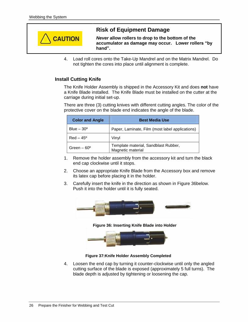
Install Cutting Knife
The Knife Holder Assembly is shipped in the Accessory Kit and does not have a Knife Blade installed. The Knife Blade must be installed on the cutter at the carriage during initial set-up.
There are three (3) cutting knives with different cutting angles. The color of the protective cover on the blade end indicates the angle of the blade.
Color and Angle Best Media Use
Blue – 30º Paper, Laminate, Film (most label applications)
Red – 45º Vinyl
Green – 60º Template material, Sandblast Rubber, Magnetic material
1. Remove the holder assembly from the accessory kit and turn the black end cap clockwise until it stops.
2. Choose an appropriate Knife Blade from the Accessory box and remove its latex cap before placing it in the holder.
3. Carefully insert the knife in the direction as shown in Figure 36below. Push it into the holder until it is fully seated.
4. Loosen the end cap by turning it counter-clockwise until only the angled cutting surface of the blade is exposed (approximately 5 full turns). The blade depth is adjusted by tightening or loosening the cap.
Figure 36: Inserting Knife Blade into Holder
Figure 37:Knife Holder Assembly Completed
Webbing the System
Prepare the Finisher for Webbing and Test Cut 27
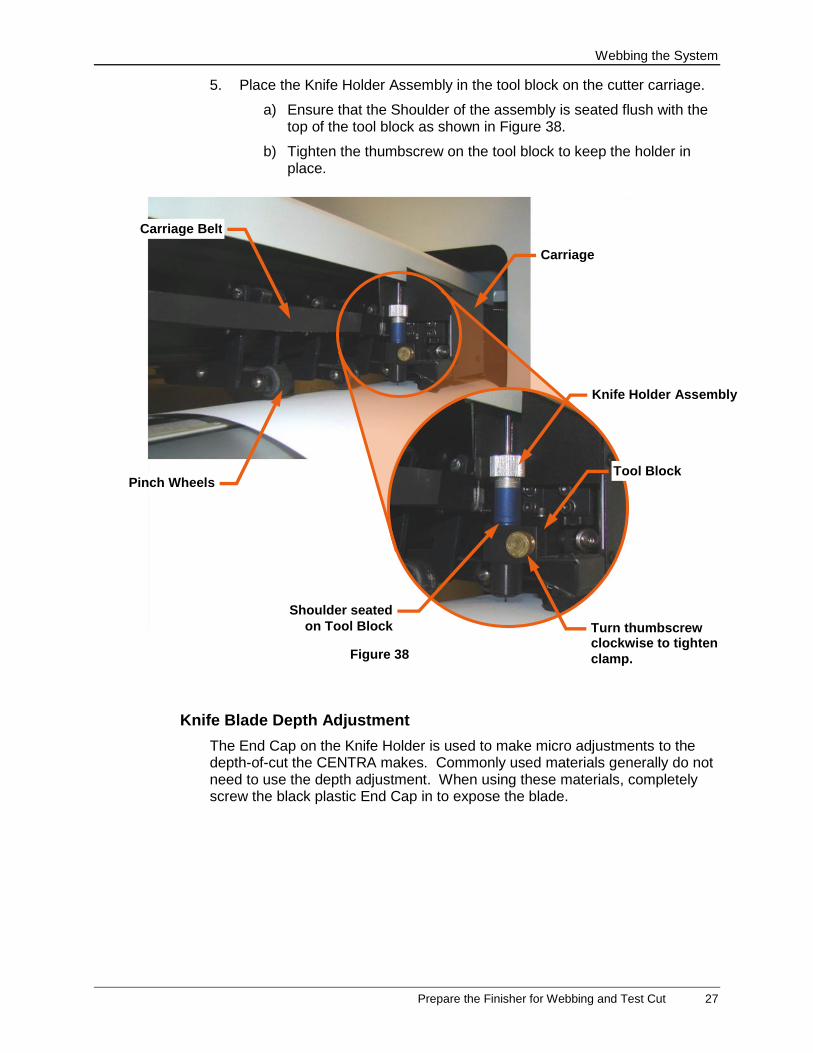
5. Place the Knife Holder Assembly in the tool block on the cutter carriage.
a) Ensure that the Shoulder of the assembly is seated flush with the top of the tool block as shown in Figure 38.
b) Tighten the thumbscrew on the tool block to keep the holder in place.
Knife Blade Depth Adjustment
The End Cap on the Knife Holder is used to make micro adjustments to the depth-of-cut the CENTRA makes. Commonly used materials generally do not need to use the depth adjustment. When using these materials, completely screw the black plastic End Cap in to expose the blade.
Figure 38
Shoulder seated
on Tool Block
Tool Block
Carriage Belt
Pinch Wheels
Knife Holder Assembly
Turn thumbscrew clockwise to tighten
clamp.
Carriage
Webbing the System
28 Web the Finisher Input Section
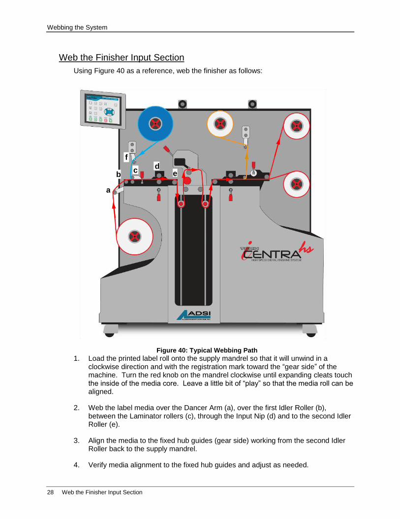
Web the Finisher Input Section
Using Figure 40 as a reference, web the finisher as follows:
1. Load the printed label roll onto the supply mandrel so that it will unwind in a clockwise direction and with the registration mark toward the “gear side” of the machine. Turn the red knob on the mandrel clockwise until expanding cleats touch the inside of the media core. Leave a little bit of “play” so that the media roll can be aligned.
2. Web the label media over the Dancer Arm (a), over the first Idler Roller (b), between the Laminator rollers (c), through the Input Nip (d) and to the second Idler Roller (e).
3. Align the media to the fixed hub guides (gear side) working from the second Idler Roller back to the supply mandrel.
4. Verify media alignment to the fixed hub guides and adjust as needed.
Figure 40: Typical Webbing Path
f
c d
e b
a

Webbing the System
Web the Finisher Input Section 29
5. Tighten the red knob on the supply mandrel so that the core is held firmly in place. Stop turning when the media core cannot be moved on the mandrel.
6. When media is aligned, rotate the roll handle (at “d”) to the 6 o’clock position to close the infeed nip rollers.
7. Align the adjustable hub guides with the edge of the media and then tighten the setscrews.
Only tighten the setscrews so that the hub guides are not loose. Idler Rollers and/or Hub Guides may be damaged if setscrews are over-tightened.
Web Laminate Material
1. If using laminate, load the appropriate mandrel with pressure-sensitive laminate material so that it unwinds in a clockwise direction.
It may be easier to web laminate if about 1” of the lead edge is folded back on itself. This allows threading without interference from adhesive.
2. Web the laminate through the Dancer Arm (f) and down to the Laminator rollers (c) to join with the label media.
3. Pull laminate through the laminator and up to the infeed nip rollers.
4. Align the center of the laminate to the center of the media.
5. Rotate the roll handle down to close the laminator rollers.
6. Cut the folded lead-edge of the laminate (before it feeds into the infeed nip).
Figure 41
Fold here
Webbing the System
30 Web the Finisher Accumulators and Cutter
Web the Finisher Accumulators and Cutter
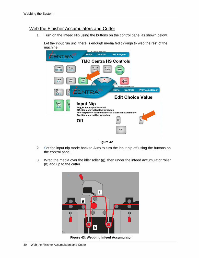
1. Turn on the Infeed Nip using the buttons on the control panel as shown below.
Let the input run until there is enough media fed through to web the rest of the machine.
2. Set the input nip mode back to Auto to turn the input nip off using the buttons on the control panel.
3. Wrap the media over the idler roller (g), then under the infeed accumulator roller (h) and up to the cutter.
Figure 42
Figure 43: Webbing Infeed Accumulator
gy
i
h
Webbing the System
Web the Finisher Accumulators and Cutter 31
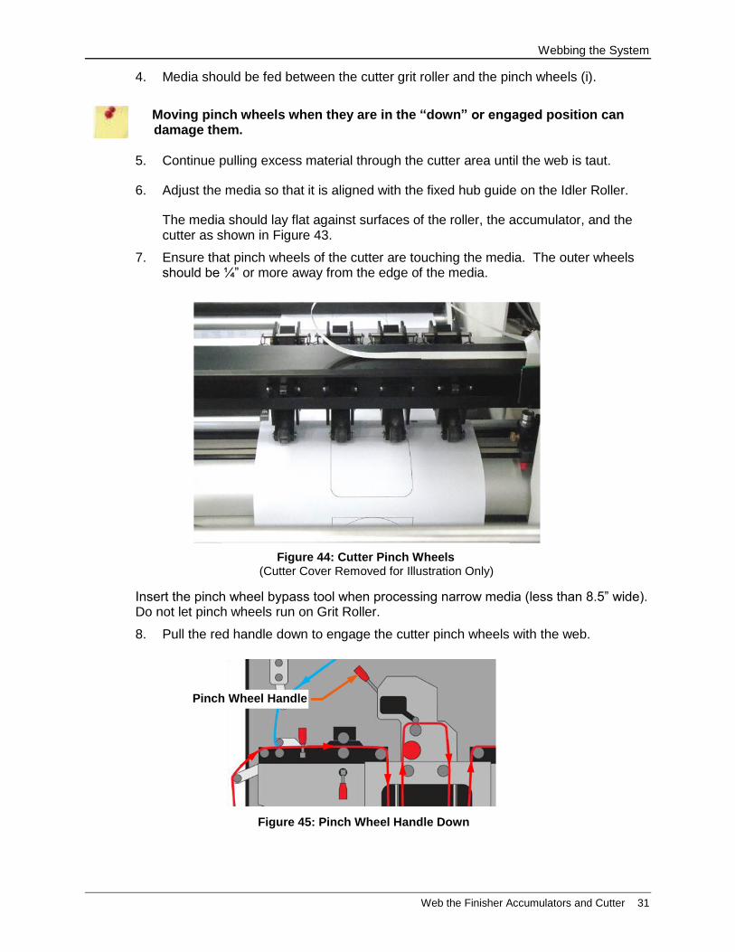
4. Media should be fed between the cutter grit roller and the pinch wheels (i).
Moving pinch wheels when they are in the “down” or engaged position can damage them.
5. Continue pulling excess material through the cutter area until the web is taut.
6. Adjust the media so that it is aligned with the fixed hub guide on the Idler Roller.
The media should lay flat against surfaces of the roller, the accumulator, and the cutter as shown in Figure 43.
7. Ensure that pinch wheels of the cutter are touching the media. The outer wheels should be ¼” or more away from the edge of the media.
Insert the pinch wheel bypass tool when processing narrow media (less than 8.5” wide). Do not let pinch wheels run on Grit Roller.
8. Pull the red handle down to engage the cutter pinch wheels with the web.
Figure 44: Cutter Pinch Wheels (Cutter Cover Removed for Illustration Only)
Figure 45: Pinch Wheel Handle Down
Pinch Wheel Handle
Webbing the System
32 Web the Matrix Mandrel and its Dancer Arm
Web the Outfeed Nip and Slitter
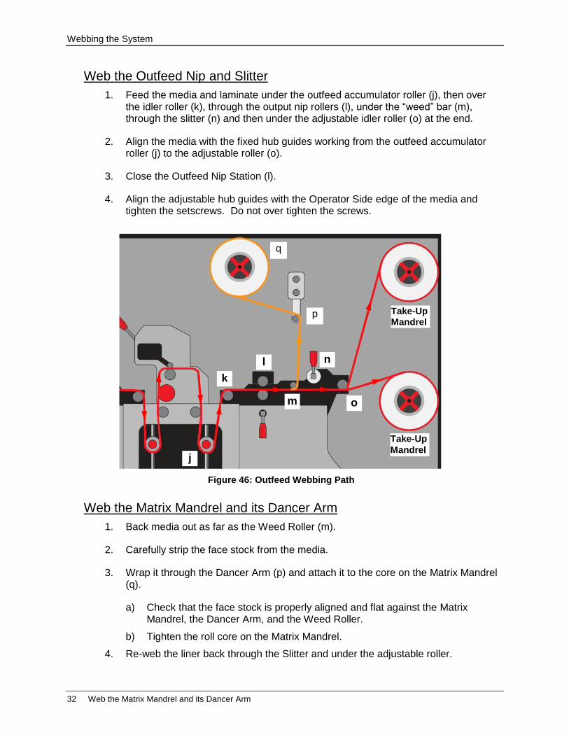
1. Feed the media and laminate under the outfeed accumulator roller (j), then over the idler roller (k), through the output nip rollers (l), under the “weed” bar (m), through the slitter (n) and then under the adjustable idler roller (o) at the end.
2. Align the media with the fixed hub guides working from the outfeed accumulator roller (j) to the adjustable roller (o).
3. Close the Outfeed Nip Station (l).
4. Align the adjustable hub guides with the Operator Side edge of the media and tighten the setscrews. Do not over tighten the screws.
Web the Matrix Mandrel and its Dancer Arm
1. Back media out as far as the Weed Roller (m).
2. Carefully strip the face stock from the media.
3. Wrap it through the Dancer Arm (p) and attach it to the core on the Matrix Mandrel (q).
a) Check that the face stock is properly aligned and flat against the Matrix Mandrel, the Dancer Arm, and the Weed Roller.
b) Tighten the roll core on the Matrix Mandrel.
4. Re-web the liner back through the Slitter and under the adjustable roller.
Figure 46: Outfeed Webbing Path
o
n
m
l
k
j
p
q
Take-Up
Mandrel
Take-Up
Mandrel
Webbing the System
Finish Webbing 33
Finish Webbing
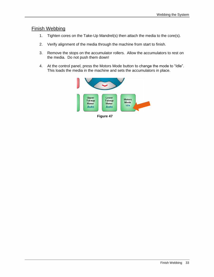
1. Tighten cores on the Take-Up Mandrel(s) then attach the media to the core(s).
2. Verify alignment of the media through the machine from start to finish.
3. Remove the stops on the accumulator rollers. Allow the accumulators to rest on the media. Do not push them down!
4. At the control panel, press the Motors Mode button to change the mode to “Idle”. This loads the media in the machine and sets the accumulators in place.
Figure 47
Set Cutting Function
34 Make a Test Cut
Set Cutting Function
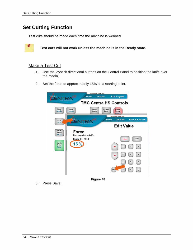
Test cuts should be made each time the machine is webbed.
Test cuts will not work unless the machine is in the Ready state.
Make a Test Cut
1. Use the joystick directional buttons on the Control Panel to position the knife over the media.
2. Set the force to approximately 15% as a starting point.
3. Press Save. Figure 48
Set Cutting Function
Make a Test Cut 35
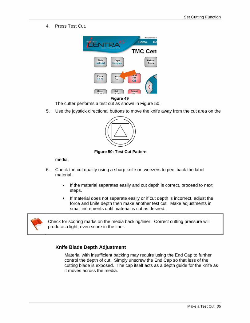
4. Press Test Cut.
The cutter performs a test cut as shown in Figure 50.
5. Use the joystick directional buttons to move the knife away from the cut area on the
media.
6. Check the cut quality using a sharp knife or tweezers to peel back the label material.
If the material separates easily and cut depth is correct, proceed to next steps.
If material does not separate easily or if cut depth is incorrect, adjust the force and knife depth then make another test cut. Make adjustments in small increments until material is cut as desired.
Check for scoring marks on the media backing/liner. Correct cutting pressure will produce a light, even score in the liner.
Knife Blade Depth Adjustment
Material with insufficient backing may require using the End Cap to further control the depth of cut. Simply unscrew the End Cap so that less of the cutting blade is exposed. The cap itself acts as a depth guide for the knife as it moves across the media.
Figure 50: Test Cut Pattern
Figure 49
Set Cutting Function
36 Align Sensor to Registration Mark
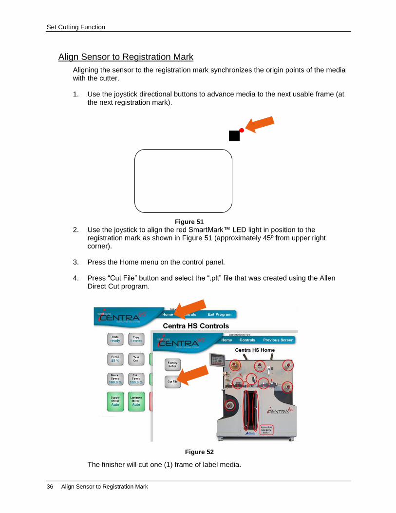
Align Sensor to Registration Mark
Aligning the sensor to the registration mark synchronizes the origin points of the media with the cutter.
1. Use the joystick directional buttons to advance media to the next usable frame (at the next registration mark).
2. Use the joystick to align the red SmartMark™ LED light in position to the registration mark as shown in Figure 51 (approximately 45º from upper right corner).
3. Press the Home menu on the control panel.
4. Press “Cut File” button and select the “.plt” file that was created using the Allen Direct Cut program.
The finisher will cut one (1) frame of label media.
Figure 51
Figure 52

Operating the CENTRA HS
Run 37
Operating the CENTRA HS
Start Up
1. Load label media and cores onto the appropriate mandrels.
2. Ensure all nip and pinch rollers are open (handles are up).
3. Turn on power.
4. Web media.
5. Ensure all nip and pinch rollers are closed (handles are down)
6. Verify “ready” state, cut force, cut speed, and move speed.
7. Send artwork/registration mark file to finisher.
8. Press “Copy” button on Control Panel and enter the number of frames to process by the machine.
Entering “-1” will run continually and count upward.
Run
The machine will begin cutting and finishing operations. The media should be periodically checked to ensure cut accuracy and proper roll alignment.
Mandrel Dancer Arm tension adjustments can be made during a run provided the machine has been put in the “Pause” state. Do not make these adjustments while the media is moving through the machine.
Mandrel Dancer Tension Adjustment
The tension settings on the front of the CENTRA HS control the amount of
tension applied to the web. Use more tension on wider materials and less tension on narrower materials. If media drifts left and/or right, more tension is probably needed. If the web is breaking or the laminate is stretching, use less tension.

Operating the CENTRA HS
38 Shut Down
The weed or matrix tension is not based on the width of the material but the width of the matrix that is left after you remove it from the backer. If your matrix is breaking, you can move the tension handle down towards the “less” position.
Shut Down
1. Wait for copies to complete or press the Pause / Ready button on the Control Panel to enter Pause mode
2. Open all nip and pinch rollers (handles are up) when machine stops.
3. Raise Accumulators and hold in place using the stops.
Accumulators should not be moved without power to machine.
4. Pull any remaining media out of the machine and wind onto the take up mandrel(s).
5. Power down control panel
6. Turn off machine power.
Leave all pinch rollers/nips open when machine is not running to prevent wear distortion to surfaces.
Operating the CENTRA HS
Home Screen 39
Using the Control Panel Program
The Control Panel Program is activated using the touching the computer screen and pressing the pictured “buttons”. Buttons display in current running state and usually toggle between states. Buttons for functions that require additional input do not toggle. A separate input screen appears.
Example: Joystick Speed reads “Fast”. This means the Joystick is running at its fast speed. Pressing the button will toggle (change) it to read “Slow” and the joystick will move at its slow speed setting.
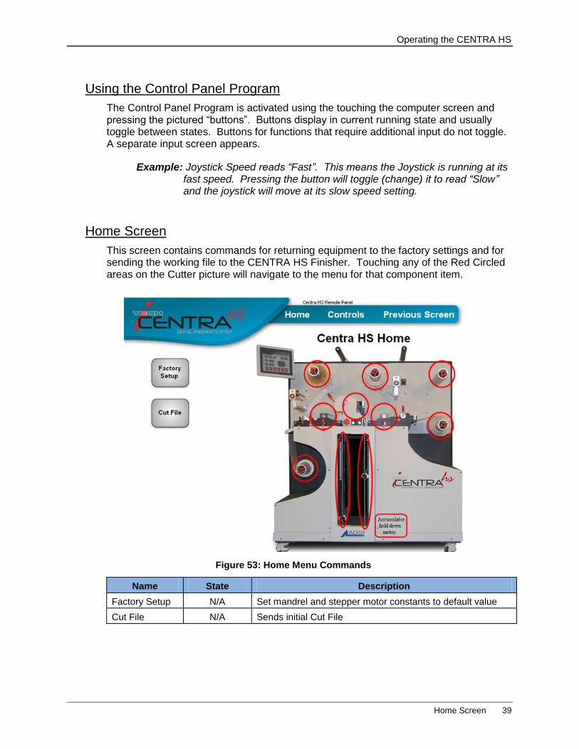
Home Screen
This screen contains commands for returning equipment to the factory settings and for sending the working file to the CENTRA HS Finisher. Touching any of the Red Circled areas on the Cutter picture will navigate to the menu for that component item.
Name State Description
Factory Setup N/A Set mandrel and stepper motor constants to default value
Cut File N/A Sends initial Cut File
Figure 53: Home Menu Commands
Operating the CENTRA HS
40 Controls Screen
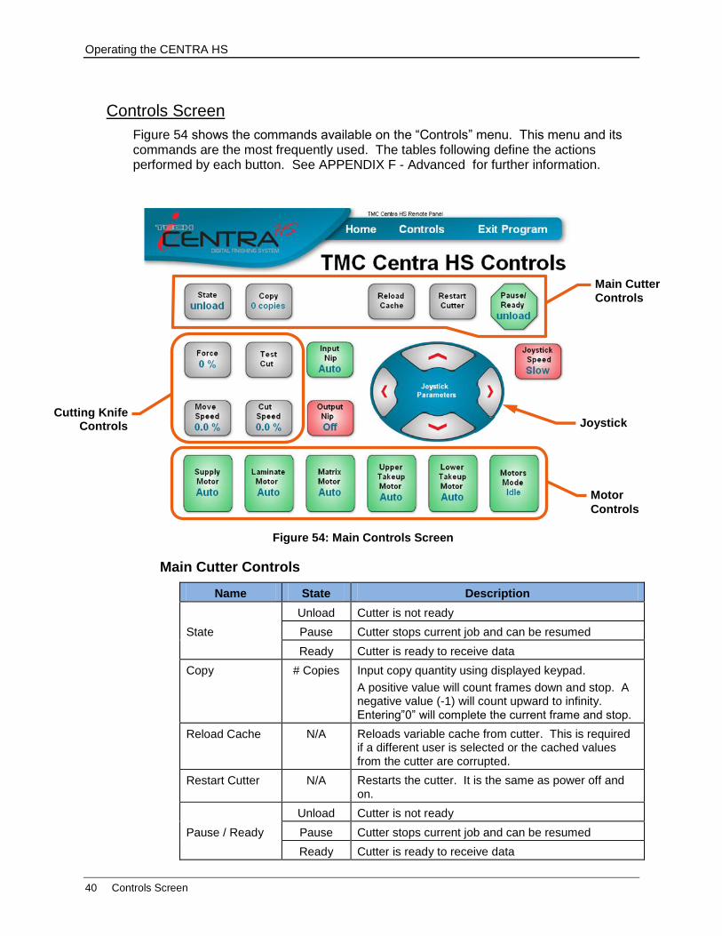
Controls Screen
Figure 54 shows the commands available on the “Controls” menu. This menu and its commands are the most frequently used. The tables following define the actions performed by each button. See APPENDIX F - Advanced for further information.
Main Cutter Controls
Name State Description
State
Unload Cutter is not ready
Pause Cutter stops current job and can be resumed
Ready Cutter is ready to receive data
Copy # Copies Input copy quantity using displayed keypad.
A positive value will count frames down and stop. A negative value (-1) will count upward to infinity. Entering”0” will complete the current frame and stop.
Reload Cache N/A Reloads variable cache from cutter. This is required if a different user is selected or the cached values from the cutter are corrupted.
Restart Cutter N/A Restarts the cutter. It is the same as power off and on.
Pause / Ready
Unload Cutter is not ready
Pause Cutter stops current job and can be resumed
Ready Cutter is ready to receive data
Figure 54: Main Controls Screen
Joystick
Motor
Controls
Cutting Knife Controls
Main Cutter
Controls
Operating the CENTRA HS
Controls Screen 41
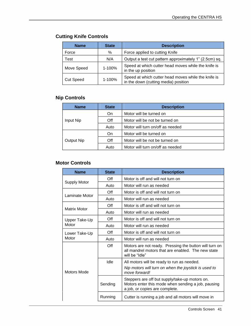
Cutting Knife Controls
Name State Description
Force % Force applied to cutting Knife
Test N/A Output a test cut pattern approximately 1” (2.5cm) sq.
Move Speed 1-100% Speed at which cutter head moves while the knife is in the up position
Cut Speed 1-100% Speed at which cutter head moves while the knife is in the down (cutting media) position
Nip Controls
Name State Description
Input Nip
On Motor will be turned on
Off Motor will be not be turned on
Auto Motor will turn on/off as needed
Output Nip
On Motor will be turned on
Off Motor will be not be turned on
Auto Motor will turn on/off as needed
Motor Controls
Name State Description
Supply Motor Off Motor is off and will not turn on
Auto Motor will run as needed
Laminate Motor Off Motor is off and will not turn on
Auto Motor will run as needed
Matrix Motor Off Motor is off and will not turn on
Auto Motor will run as needed
Upper Take-Up Motor
Off Motor is off and will not turn on
Auto Motor will run as needed
Lower Take-Up Motor
Off Motor is off and will not turn on
Auto Motor will run as needed
Motors Mode
Off Motors are not ready. Pressing the button will turn on all mandrel motors that are enabled. The new state will be “Idle”
Idle All motors will be ready to run as needed.
Nip motors will turn on when the joystick is used to move forward!
Sending Steppers are off but supply/take-up motors on. Motors enter this mode when sending a job, pausing a job, or copies are complete.
Running Cutter is running a job and all motors will move in
Operating the CENTRA HS
42 Controls Screen
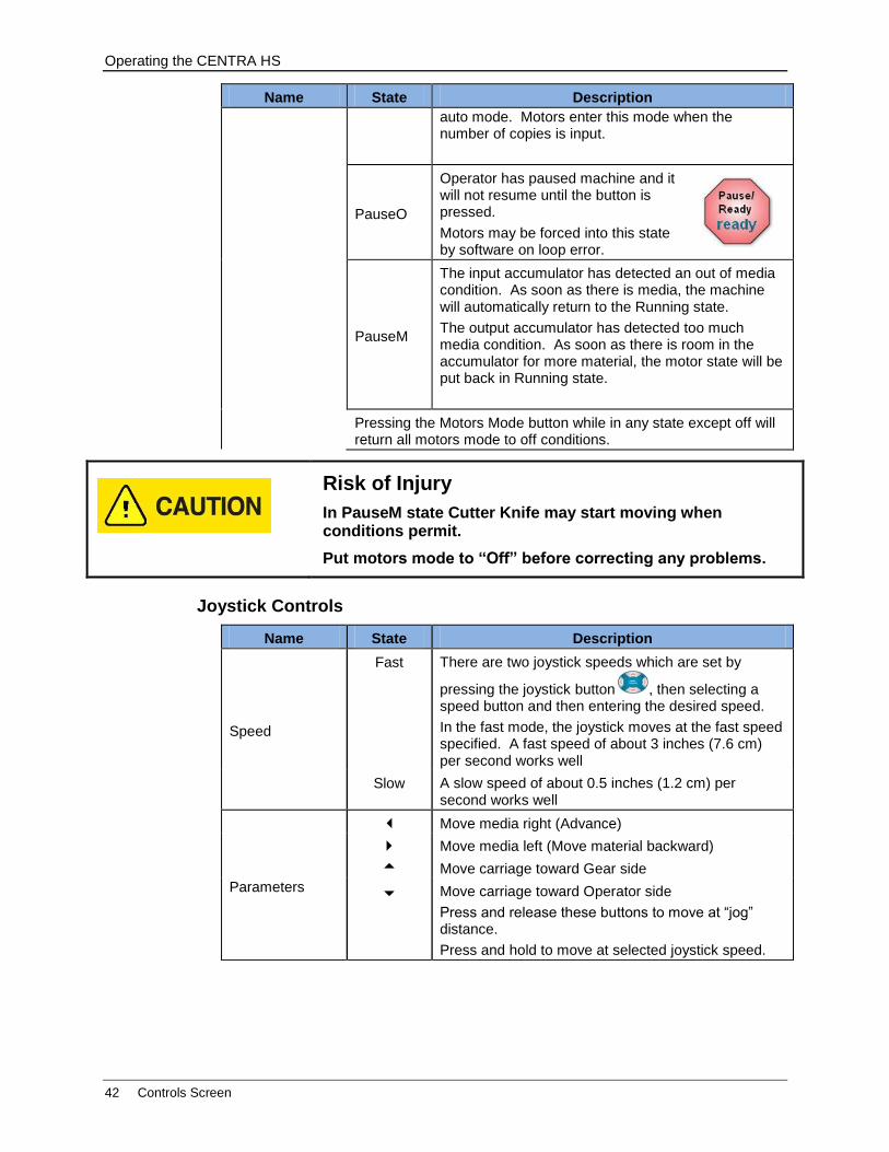
Name State Description
auto mode. Motors enter this mode when the number of copies is input.
PauseO
Operator has paused machine and it will not resume until the button is pressed.
Motors may be forced into this state by software on loop error.
PauseM
The input accumulator has detected an out of media condition. As soon as there is media, the machine will automatically return to the Running state.
The output accumulator has detected too much media condition. As soon as there is room in the accumulator for more material, the motor state will be put back in Running state.
Pressing the Motors Mode button while in any state except off will return all motors mode to off conditions.
Risk of Injury
In PauseM state Cutter Knife may start moving when conditions permit.
Put motors mode to “Off” before correcting any problems.
Joystick Controls
Name State Description
Speed
Fast There are two joystick speeds which are set by
pressing the joystick button , then selecting a speed button and then entering the desired speed.
In the fast mode, the joystick moves at the fast speed specified. A fast speed of about 3 inches (7.6 cm) per second works well
Slow A slow speed of about 0.5 inches (1.2 cm) per second works well
Parameters
Move media right (Advance)
Move media left (Move material backward)
Move carriage toward Gear side
Move carriage toward Operator side
Press and release these buttons to move at “jog” distance.
Press and hold to move at selected joystick speed.

Operating the CENTRA HS
Exit Program 43
Previous Screen
This screen option will return to the screen shown immediately before the current display.
When entering numeric values, pressing “previous screen” before pressing “save” will return to preceding screen without new data input.
Exit Program
Pressing this button exits the program and returns to the windows home screen so the operator can shutdown the PC.
The control panel program can also be exited or minimized by touching the screen name and pressing the Exit, Minimize or exit buttons.
Double touching the TMC Remote Panel icon on the desktop will restart the panel.
Follow these steps to shut down the program and restart it:
1. Touch the keyboard flyout button twice
2. Enter alt and then tab.
3. Select the desktop.
4. Click on the start button and type “task man” in the search box and then select the task manager.
5. Select the TMC remote panel and end the task.
Operating the CENTRA HS
44 Using Accessories
Using Accessories
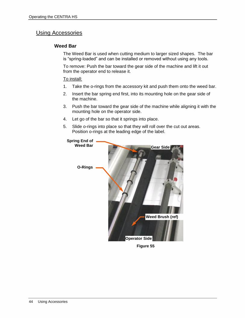
Weed Bar
The Weed Bar is used when cutting medium to larger sized shapes. The bar is “spring-loaded” and can be installed or removed without using any tools.
To remove: Push the bar toward the gear side of the machine and lift it out from the operator end to release it.
To install:
1. Take the o-rings from the accessory kit and push them onto the weed bar.
2. Insert the bar spring end first, into its mounting hole on the gear side of the machine.
3. Push the bar toward the gear side of the machine while aligning it with the mounting hole on the operator side.
4. Let go of the bar so that it springs into place.
5. Slide o-rings into place so that they will roll over the cut out areas. Position o-rings at the leading edge of the label.
Figure 55
O-Rings
Spring End of Weed Bar
Weed Brush (ref)
Gear Side
Operator Side
Operating the CENTRA HS
Using Accessories 45
Weed Brush
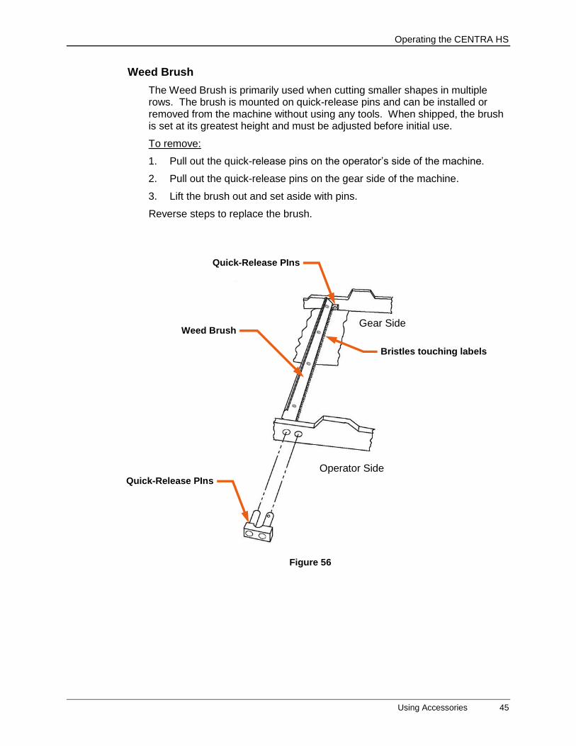
The Weed Brush is primarily used when cutting smaller shapes in multiple rows. The brush is mounted on quick-release pins and can be installed or removed from the machine without using any tools. When shipped, the brush is set at its greatest height and must be adjusted before initial use.
To remove:
1. Pull out the quick-release pins on the operator’s side of the machine.
2. Pull out the quick-release pins on the gear side of the machine.
3. Lift the brush out and set aside with pins.
Reverse steps to replace the brush.
Figure 56
Gear Side
Operator Side
Quick-Release PIns
Quick-Release PIns
Weed Brush
Bristles touching labels
Operating the CENTRA HS
46 Using Accessories
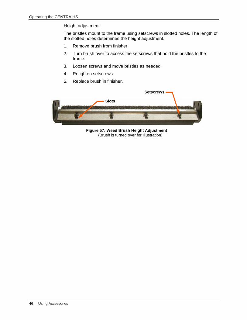
Height adjustment:
The bristles mount to the frame using setscrews in slotted holes. The length of the slotted holes determines the height adjustment.
1. Remove brush from finisher
2. Turn brush over to access the setscrews that hold the bristles to the frame.
3. Loosen screws and move bristles as needed.
4. Retighten setscrews.
5. Replace brush in finisher.
Figure 57: Weed Brush Height Adjustment (Brush is turned over for Illustration)
Setscrews
Slots

Maintenance & Consumables
Fuses 47
Maintenance & Consumables
Operating maintenance performed on this machine will only require the tools that were shipped in the Accessories box. Please see Accessory Kit for a complete list of tools and parts that shipped with the unit.
Replacement parts and tools may be ordered using our online store at www.allendatagraph.com.
Fuses
There are two (2) spare fuses provided with the Finisher. If you have 110v AC use one 10-amp fuse. If you have 220v AC use two 5-amp fuses (remove the shorting clip to use two fuses).
Replacing a Fuse
1. Disconnect the AC power cord from the fuse block on the power input end panel.
2. Open the fuse block cover with a small flat screwdriver and pull out the fuse block.
3. Remove the spent fuse and replace with a new one.
4. Orient the fuse block so that the desired voltage appears in the fuse block cover.
5. Close the fuse block cover and verify that the desired voltage is showing.
Figure 59: Fuse Block
Fuse for 115V system Fuses for 230V system on both sides
Figure 58: Fuse Block Access
Fuse Block Cover
Fuse Block
Maintenance & Consumables
48 Cutting Blades
Cutting Blades
Changing a Knife Blade
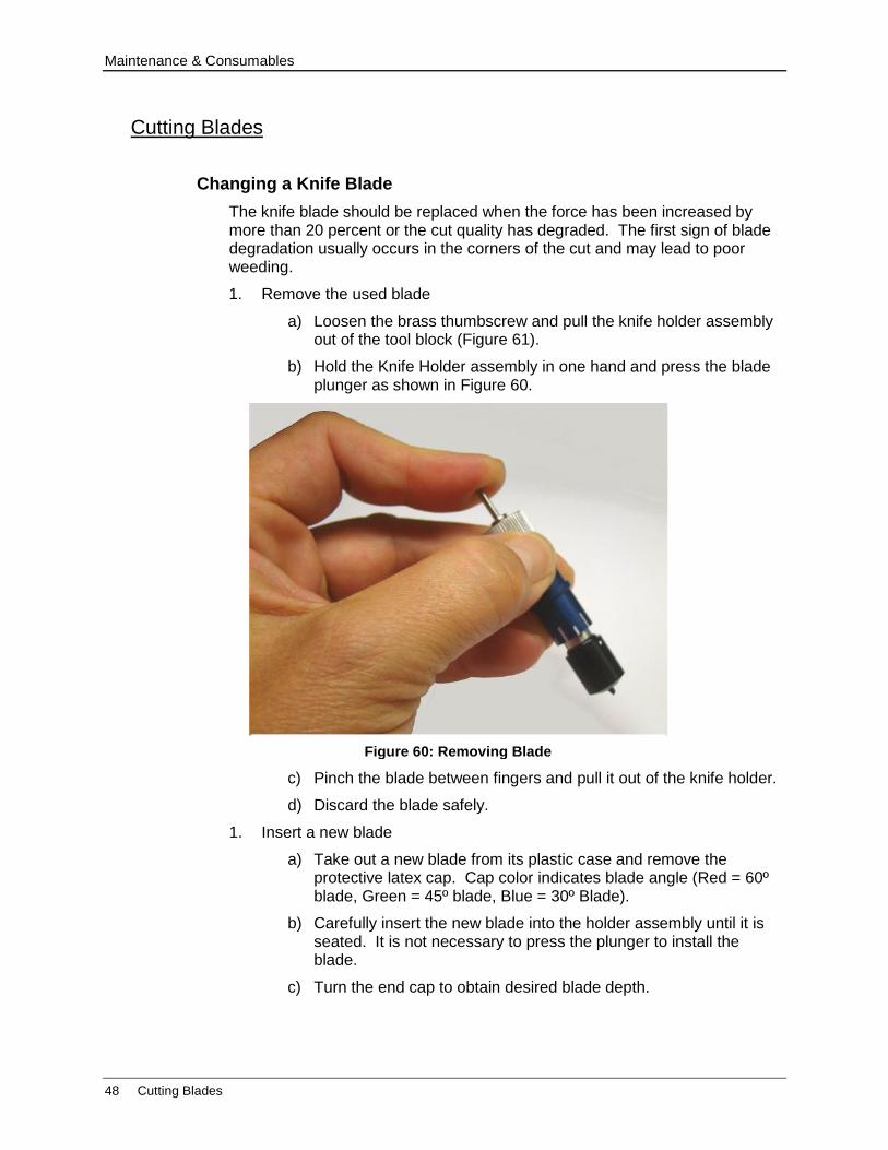
The knife blade should be replaced when the force has been increased by more than 20 percent or the cut quality has degraded. The first sign of blade degradation usually occurs in the corners of the cut and may lead to poor weeding.
1. Remove the used blade
a) Loosen the brass thumbscrew and pull the knife holder assembly out of the tool block (Figure 61).
b) Hold the Knife Holder assembly in one hand and press the blade plunger as shown in Figure 60.
c) Pinch the blade between fingers and pull it out of the knife holder.
d) Discard the blade safely.
1. Insert a new blade
a) Take out a new blade from its plastic case and remove the protective latex cap. Cap color indicates blade angle (Red = 60º blade, Green = 45º blade, Blue = 30º Blade).
b) Carefully insert the new blade into the holder assembly until it is seated. It is not necessary to press the plunger to install the blade.
c) Turn the end cap to obtain desired blade depth.
Figure 60: Removing Blade
Maintenance & Consumables
Cutting Blades 49
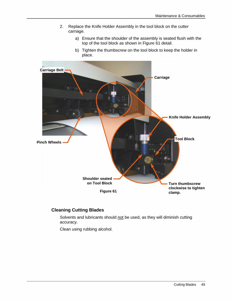
2. Replace the Knife Holder Assembly in the tool block on the cutter carriage.
a) Ensure that the shoulder of the assembly is seated flush with the top of the tool block as shown in Figure 61 detail.
b) Tighten the thumbscrew on the tool block to keep the holder in place.
Cleaning Cutting Blades
Solvents and lubricants should not be used, as they will diminish cutting accuracy.
Clean using rubbing alcohol.
Figure 61
Shoulder seated
on Tool Block
Tool Block
Carriage Belt
Pinch Wheels
Knife Holder Assembly
Turn thumbscrew clockwise to tighten
clamp.
Carriage

Maintenance & Consumables
50 Changing a Cut Strip
Changing a Cut Strip
The Cut Strip should be replaced when the cut quality of the media deteriorates.
1. Move the knife carriage to the gear side of the cutter.
2. Clean any debris from the cut strip area before removing the existing strip.
3. Use the Cut Strip Removal Tool to remove the worn strip.
a) Place the hooked end of the tool under one end of the Cut Strip
b) Pull up gently until there is enough material to pull using your hand.
Cut Strips are held in place with light adhesive and should be easy to remove.
4. Clean any debris from the groove and inspect before installing the new Cut Strip.
5. Peel the backing off the new cut strip and place in groove.
6. Press down firmly to ensure proper seating.
It is important to install the Cut Strip fully and evenly, otherwise material “cut through” may occur in some sections across the cutter.
Two different cut strips are available from the http://allendatagraph.com online store. “Normal life” and “extended life” cut strips.
Figure 64: Removing the Cut Strip
Figure 63: Cut Strip Removal Tool

Maintenance & Consumables
Cleaning the CENTRA HS Finisher 51
Cleaning the CENTRA HS Finisher
The regularity with which the cutter needs to be cleaned is dependent on the usage, as well as the climate and contaminants in the cutter’s environment. It is recommended that the following cleaning steps be done at least as often as indicated for each procedure.
Items needed for cleaning:
Small bristle brush (toothbrush), soft cloths, rubber roller cleaner, mild solution of soap and water.
Annual cleaning requires the use of a grounding strap to prevent damage to electronic equipment, compressed air, and safety glasses to protect eyes while using the compressed air.
Biweekly Cleaning
Grit Rollers
The grit rollers on the cutter and the nips move the media through the finisher. Keeping the grit rollers clean allows the cutter to hold the media properly. Clean the grit rolls with a stiff bristled brush (e.g. toothbrush) to remove any media particles built up during cutting.
1. Disconnect power from machine
2. Disengage rubber rollers and pinch wheels from the grit rollers (handles in up position)
3. Do not use a wire bristle brush. A wire brush will damage the Grit Roller.
4. Brush the surface of the grit wheel while turning the grit roller by hand so the entire surface of the grit wheel is cleaned.
ALWAYS disconnect the power source while cleaning any part of the machine. Keep power source disconnected until the cleaning process is completed.
Figure 65: Grit Roller on Cutter
Grit Roller
Pinch Wheels
Cut Strip (ref)

Maintenance & Consumables
52 Cleaning the CENTRA HS Finisher
Pinch Wheels
Wipe media-related dust from the set of polyurethane pinch wheels using a soft cloth. To clean adhesive off the pinch wheels, simply use a soft cloth and rubber roller cleaner.
See also “Pinch Wheel Maintenance”.
Rubber Rollers and Wheels
Clean using rubber roller cleaner and a soft cloth. Adhesive build-up may be removed using the roller cleaner and gently scraping the surface with a fingernail.
Use a rubber roller cleaner such as the type sold in office supply stores. Avoid using isopropyl or denatured alcohol on rubber parts. Alcohol will dry and harden the surfaces.
Metal Rollers and Guides
Inspect for dust or adhesive build up. Remove dust using a soft cloth. Adhesive build-up may be removed using a small amount of Isopropyl alcohol and gentle scraping with a fingernail.
Monthly Cleaning
Clean the outer surface of the machine. If necessary, a mild cleaning solution (such as mild soap and water) on a damp cloth can be used to gently wipe painted surfaces clean.
Do not use abrasive cleaners. Abrasive cleaners will cause the paint to blister.
Use a solution of mild soap and water.
Annual Cleaning
Observe static discharge safety procedures that may damage sensitive electronic components. Wear a grounding strap connected to earth ground. Wear safety glasses to protect eyes.
1. Remove rear cover
2. Use compressed air to remove dust and debris.
3. Inspect the internal circuit board assemblies and clean accumulated dust as necessary.
4. Make certain that the boards and any connectors are well seated.
5. Replace cover to original location.
Maintenance & Consumables
Cleaning the CENTRA HS Finisher 53
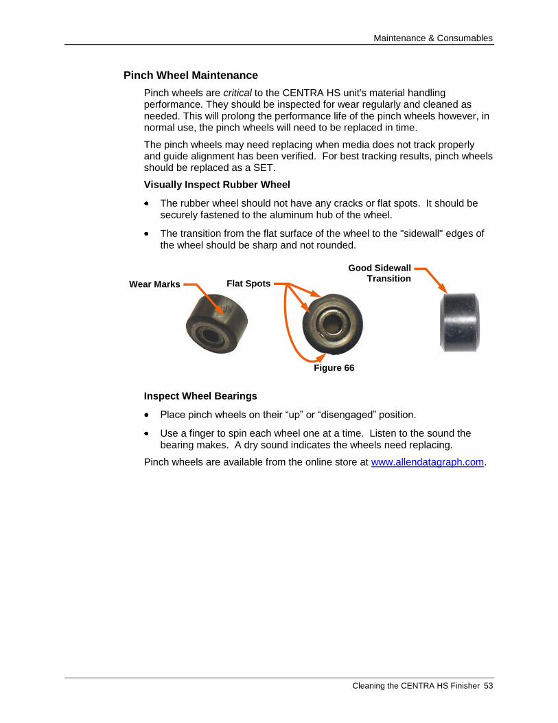
Pinch Wheel Maintenance
Pinch wheels are critical to the CENTRA HS unit's material handling performance. They should be inspected for wear regularly and cleaned as needed. This will prolong the performance life of the pinch wheels however, in normal use, the pinch wheels will need to be replaced in time.
The pinch wheels may need replacing when media does not track properly and guide alignment has been verified. For best tracking results, pinch wheels should be replaced as a SET.
Visually Inspect Rubber Wheel
The rubber wheel should not have any cracks or flat spots. It should be securely fastened to the aluminum hub of the wheel.
The transition from the flat surface of the wheel to the "sidewall" edges of the wheel should be sharp and not rounded.
Inspect Wheel Bearings
Place pinch wheels on their “up” or “disengaged” position.
Use a finger to spin each wheel one at a time. Listen to the sound the bearing makes. A dry sound indicates the wheels need replacing.
Pinch wheels are available from the online store at www.allendatagraph.com.
Figure 66
Wear Marks
Good Sidewall Transition
Flat Spots
Maintenance & Consumables
54 Belt Adjustments
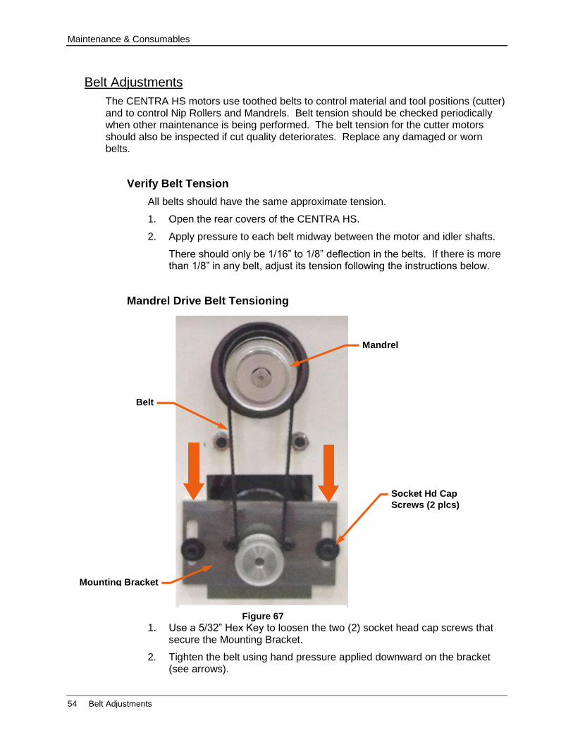
Belt Adjustments
The CENTRA HS motors use toothed belts to control material and tool positions (cutter) and to control Nip Rollers and Mandrels. Belt tension should be checked periodically when other maintenance is being performed. The belt tension for the cutter motors should also be inspected if cut quality deteriorates. Replace any damaged or worn belts.
Verify Belt Tension
All belts should have the same approximate tension.
1. Open the rear covers of the CENTRA HS.
2. Apply pressure to each belt midway between the motor and idler shafts.
There should only be 1/16” to 1/8” deflection in the belts. If there is more than 1/8” in any belt, adjust its tension following the instructions below.
Mandrel Drive Belt Tensioning
1. Use a 5/32” Hex Key to loosen the two (2) socket head cap screws that secure the Mounting Bracket.
2. Tighten the belt using hand pressure applied downward on the bracket (see arrows).
Figure 67
Socket Hd Cap
Screws (2 plcs)
Mounting Bracket
Mandrel
Belt
Maintenance & Consumables
Belt Adjustments 55
3. Apply pressure until the belt deflects 1/16” inch (1.3 mm) at the center when tension is applied.
4. Retighten the socket head cap screws when the belt is tight.
5. Verify tension.
Repeat above steps for remaining mandrels
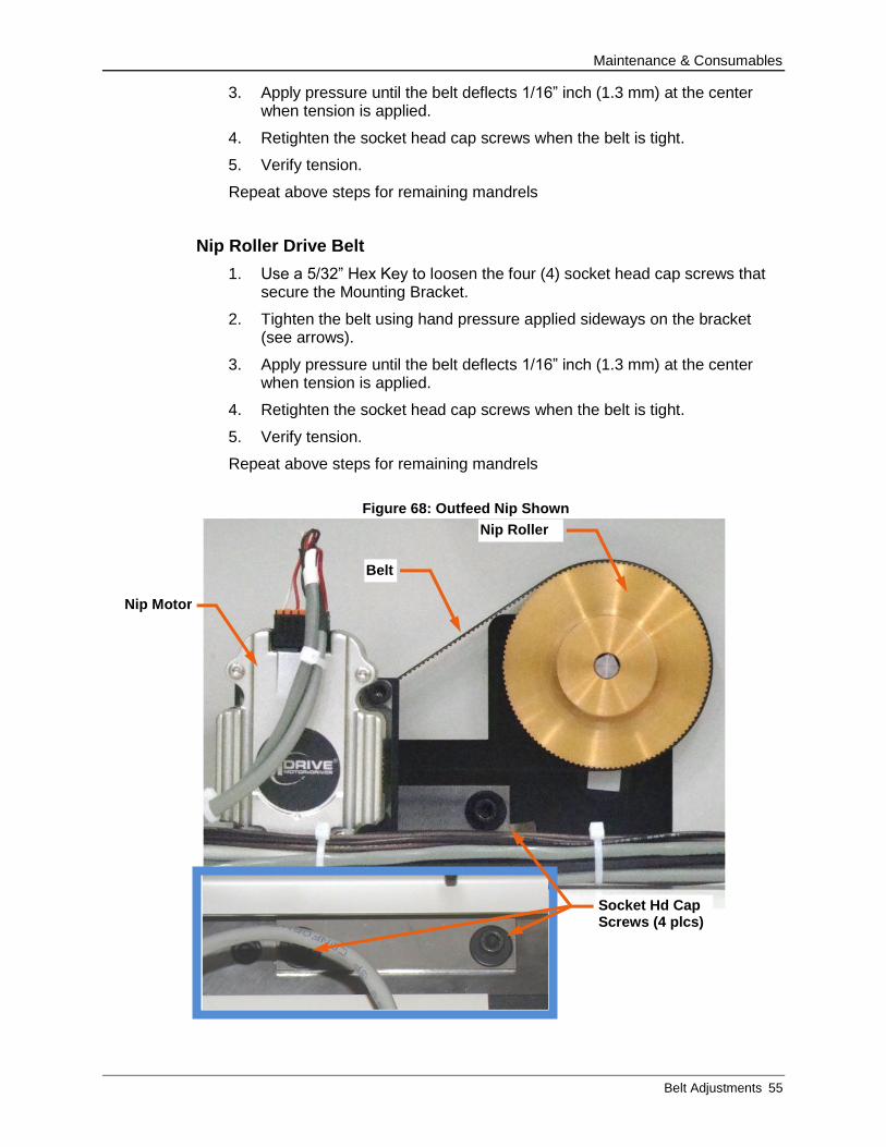
Nip Roller Drive Belt
1. Use a 5/32” Hex Key to loosen the four (4) socket head cap screws that secure the Mounting Bracket.
2. Tighten the belt using hand pressure applied sideways on the bracket (see arrows).
3. Apply pressure until the belt deflects 1/16” inch (1.3 mm) at the center when tension is applied.
4. Retighten the socket head cap screws when the belt is tight.
5. Verify tension.
Repeat above steps for remaining mandrels
Figure 68: Outfeed Nip Shown
Belt
Nip Roller
Nip Motor
Socket Hd Cap Screws (4 plcs)

Maintenance & Consumables
56 Belt Adjustments
Adjust Carriage (Y-Axis) Drive Belt Tension
The Carriage drive belt runs between the Y-axis servomotor and a gear assembly. To adjust the tension of this belt, it is necessary to reposition the motor bracket.
1. Open the rear covers of the CENTRA HS.
2. Use a 5/32” Hex Key to loosen the four (4) socket head cap screws that secure the Y motor bracket to the side plate.
3. Tighten the belt using hand pressure applied to the motor housing.
4. Apply pressure until the belt deflects 1/16” inch (1.3 mm) at the center when tension is applied.
5. Retighten the socket head cap screws when the belt is tight. Ensure that and the motor shaft is parallel to the idler shaft bracket and perpendicular to the frame.
6. Verify tension.
The motor bracket for the Y-Axis motor must be aligned so that it is both parallel to the idler shaft as well as perpendicular to the equipment frame.
Figure 69: Carriage Belt Motor
Y-Axis Motor Mounting Bracket
Y-Axis Motor (Carriage Belt)
Y-Axis Idler
Gear Assy
Socket Head Cap Screws (4 total)
Y-Axis Motor Shaft
Carriaage
Timing Belt
Equipment Frame
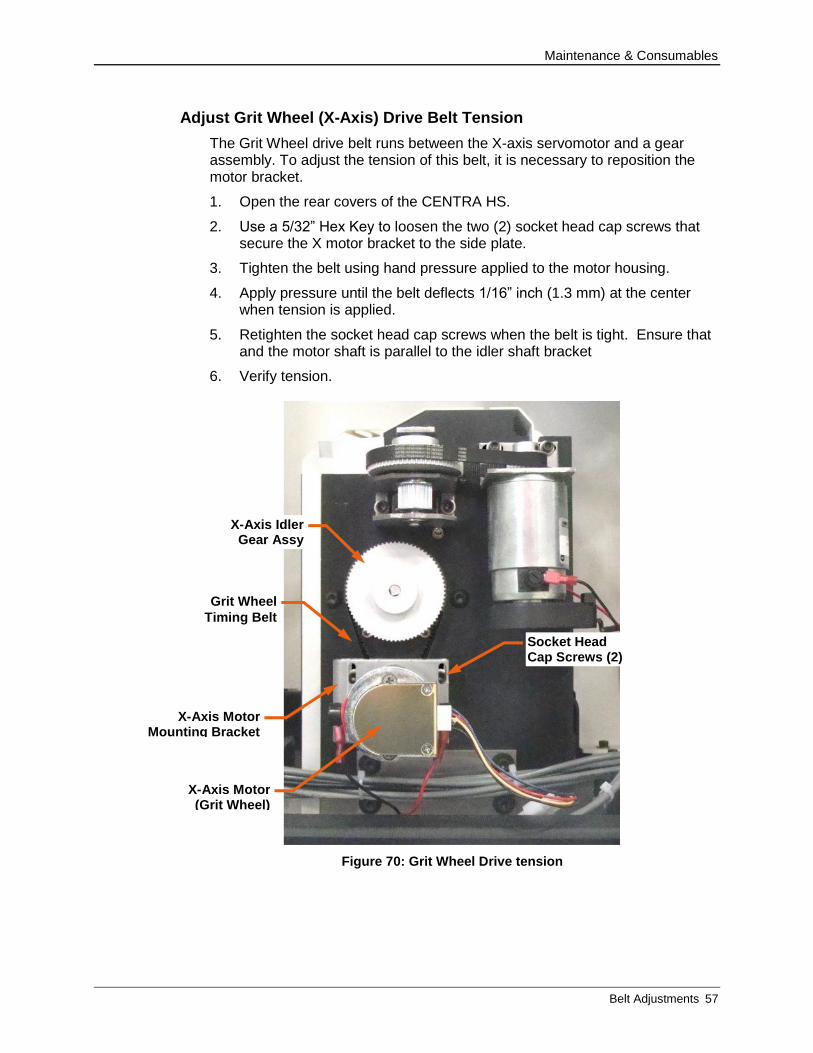
Maintenance & Consumables
Belt Adjustments 57
Adjust Grit Wheel (X-Axis) Drive Belt Tension
The Grit Wheel drive belt runs between the X-axis servomotor and a gear assembly. To adjust the tension of this belt, it is necessary to reposition the motor bracket.
1. Open the rear covers of the CENTRA HS.
2. Use a 5/32” Hex Key to loosen the two (2) socket head cap screws that secure the X motor bracket to the side plate.
3. Tighten the belt using hand pressure applied to the motor housing.
4. Apply pressure until the belt deflects 1/16” inch (1.3 mm) at the center when tension is applied.
5. Retighten the socket head cap screws when the belt is tight. Ensure that and the motor shaft is parallel to the idler shaft bracket
6. Verify tension.
Figure 70: Grit Wheel Drive tension
X-Axis Motor Mounting Bracket
X-Axis Idler Gear Assy
Socket Head Cap Screws (2)
Grit Wheel
Timing Belt
X-Axis Motor (Grit Wheel)
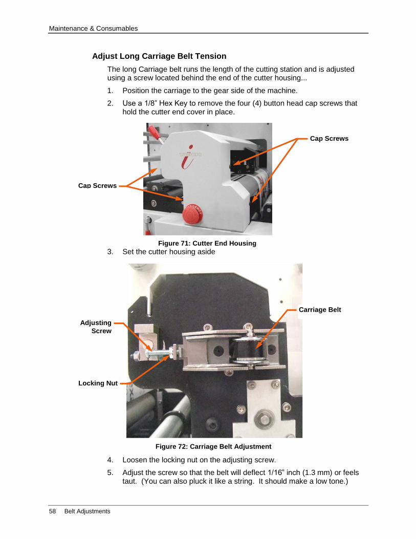
Maintenance & Consumables
58 Belt Adjustments
Adjust Long Carriage Belt Tension
The long Carriage belt runs the length of the cutting station and is adjusted using a screw located behind the end of the cutter housing...
1. Position the carriage to the gear side of the machine.
2. Use a 1/8” Hex Key to remove the four (4) button head cap screws that hold the cutter end cover in place.
3. Set the cutter housing aside
4. Loosen the locking nut on the adjusting screw.
5. Adjust the screw so that the belt will deflect 1/16” inch (1.3 mm) or feels taut. (You can also pluck it like a string. It should make a low tone.)
Figure 71: Cutter End Housing
Cap Screws
Cap Screws
Figure 72: Carriage Belt Adjustment
Adjusting
Screw
Locking Nut
Carriage Belt

Maintenance & Consumables
Belt Adjustments 59
6. Move the carriage slowly to the center of the rail to equalize tension on pulleys. Check tension again.
7. Set the adjusting screw lock nut.
8. Check belt path and tension.
9. Replace the cutter housing.

Operating File Creation
60 Registration Mark Placement and File Creation
APPENDIX A - Operating File Creation
Files are created to add registration marks and cutting paths to label artwork. Once this is done, a “Cut” file is created using Allen DirectCut to send the information to the CENTRA HS when the media is processed through it.
Explanation of SmartMarkTM
The SmartMarkTM for ADSI i-TECH cutters is an optical registration system that ensures accurate cutting of pre-printed graphics. The SmartMark™ system can recognize up to three registration marks per frame allowing adjustments for scale and skew discrepancies that may occur.
The SmartMarkTM sensor recognizes the change in contrast from the background media to the printed mark. The sensor sends a signal when the mark is scanned by the finisher. The software calculates the position of the scanned mark and matches it with its corresponding origin point of the cut file.
The registration mark(s) and die line(s) define the cutting area for each “Frame” of the printed label media. A registration mark and a die line must be created to use with the label artwork so that the CENTRA HS Finisher can cut the labels accurately. This is done by creating a new file that contains the artwork and registration mark on one layer and the die or cut line on a separate layer.
Registration Mark Placement and File Creation
Follow the steps below to create the new label-cutting file with the registration mark set at “origin”.
1. Open an existing working artwork file (pdf, eps, Ai, CorelDraw)
2. Make the art board height equal to the label media width. This helps to visualize the actual size of the frame.
3. Name the current layer with your artwork “Artwork”.
4. Click on the rectangle tool; its properties should be set to black fill with no stroke.
5. Click in the upper right area of the art board and create a box that is ¼” square.
6. Create a new layer and label it “Die Line”.
7. Make the “Die Line” layer active.
If you have it available from another file, cut and paste a die line to the die line layer.
If there is no die line file, create the die line using the shape or pen tools.
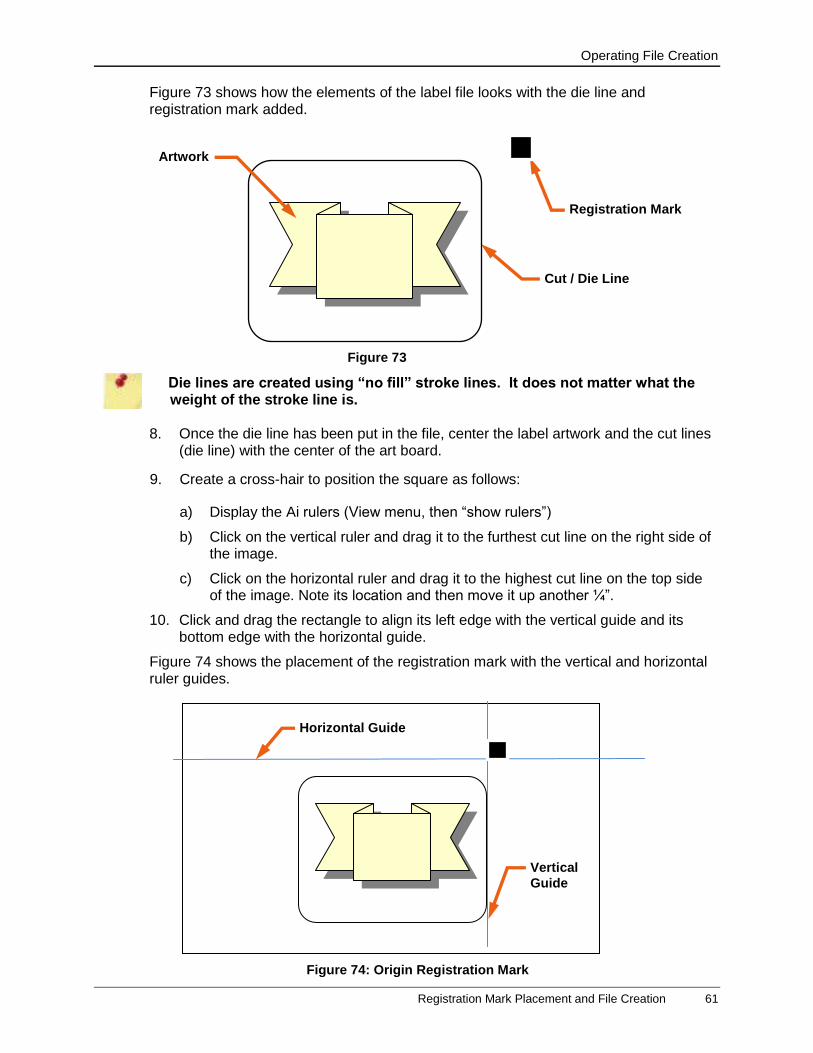
Operating File Creation
Registration Mark Placement and File Creation 61
Figure 73 shows how the elements of the label file looks with the die line and registration mark added.
Die lines are created using “no fill” stroke lines. It does not matter what the weight of the stroke line is.
8. Once the die line has been put in the file, center the label artwork and the cut lines (die line) with the center of the art board.
9. Create a cross-hair to position the square as follows:
a) Display the Ai rulers (View menu, then “show rulers”)
b) Click on the vertical ruler and drag it to the furthest cut line on the right side of the image.
c) Click on the horizontal ruler and drag it to the highest cut line on the top side of the image. Note its location and then move it up another ¼”.
10. Click and drag the rectangle to align its left edge with the vertical guide and its bottom edge with the horizontal guide.
Figure 74 shows the placement of the registration mark with the vertical and horizontal ruler guides.
Figure 73
Registration Mark
Cut / Die Line
Artwork
Vertical
Guide
Horizontal Guide
Figure 74: Origin Registration Mark
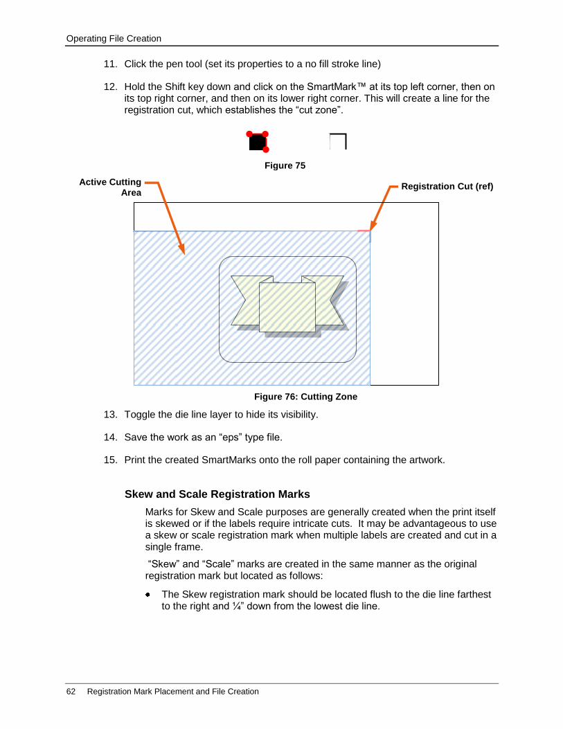
Operating File Creation
62 Registration Mark Placement and File Creation
11. Click the pen tool (set its properties to a no fill stroke line)
12. Hold the Shift key down and click on the SmartMark™ at its top left corner, then on its top right corner, and then on its lower right corner. This will create a line for the registration cut, which establishes the “cut zone”.
13. Toggle the die line layer to hide its visibility.
14. Save the work as an “eps” type file.
15. Print the created SmartMarks onto the roll paper containing the artwork.
Skew and Scale Registration Marks
Marks for Skew and Scale purposes are generally created when the print itself is skewed or if the labels require intricate cuts. It may be advantageous to use a skew or scale registration mark when multiple labels are created and cut in a single frame.
“Skew” and “Scale” marks are created in the same manner as the original registration mark but located as follows:
The Skew registration mark should be located flush to the die line farthest to the right and ¼” down from the lowest die line.
Figure 75
Registration Cut (ref)
Figure 76: Cutting Zone
Active Cutting Area
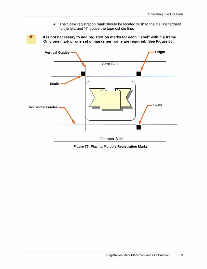
Operating File Creation
Registration Mark Placement and File Creation 63
The Scale registration mark should be located flush to the die line farthest to the left, and ¼” above the topmost die line.
It is not necessary to add registration marks for each “label” within a frame. Only one mark or one set of marks per frame are required. See Figure 80.
Vertical Guides
Horizontal Guides
Figure 77: Placing Multiple Registration Marks
Origin
Skew
Scale
Gear Side
Operator Side
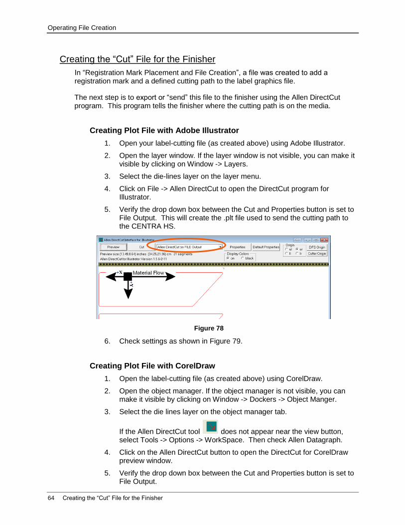
Operating File Creation
64 Creating the “Cut” File for the Finisher
Creating the “Cut” File for the Finisher
In “Registration Mark Placement and File Creation”, a file was created to add a registration mark and a defined cutting path to the label graphics file.
The next step is to export or “send” this file to the finisher using the Allen DirectCut program. This program tells the finisher where the cutting path is on the media.
Creating Plot File with Adobe Illustrator
1. Open your label-cutting file (as created above) using Adobe Illustrator.
2. Open the layer window. If the layer window is not visible, you can make it visible by clicking on Window -> Layers.
3. Select the die-lines layer on the layer menu.
4. Click on File -> Allen DirectCut to open the DirectCut program for Illustrator.
5. Verify the drop down box between the Cut and Properties button is set to File Output. This will create the .plt file used to send the cutting path to the CENTRA HS.
6. Check settings as shown in Figure 79.
Creating Plot File with CorelDraw
1. Open the label-cutting file (as created above) using CorelDraw.
2. Open the object manager. If the object manager is not visible, you can make it visible by clicking on Window -> Dockers -> Object Manger.
3. Select the die lines layer on the object manager tab.
If the Allen DirectCut tool does not appear near the view button, select Tools -> Options -> WorkSpace. Then check Allen Datagraph.
4. Click on the Allen DirectCut button to open the DirectCut for CorelDraw preview window.
5. Verify the drop down box between the Cut and Properties button is set to File Output.
Figure 78
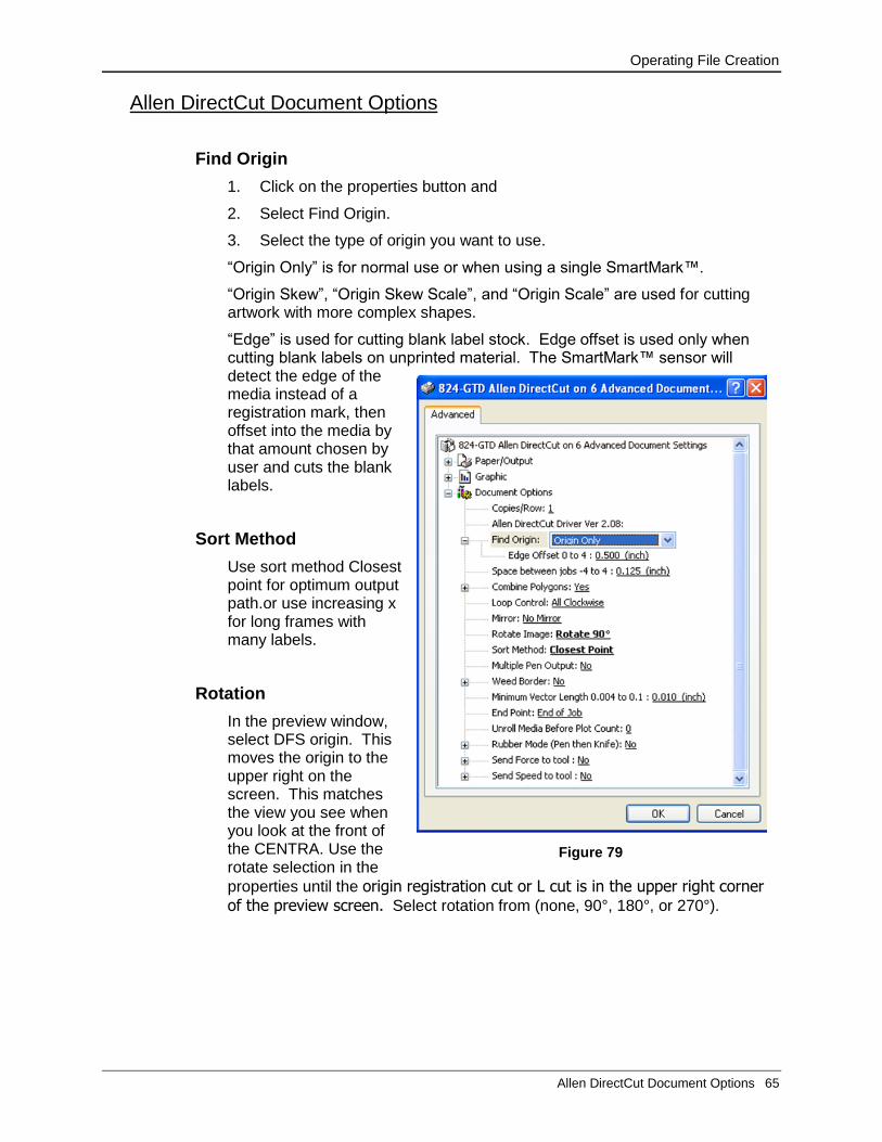
Operating File Creation
Allen DirectCut Document Options 65
Allen DirectCut Document Options
Find Origin
1. Click on the properties button and
2. Select Find Origin.
3. Select the type of origin you want to use.
“Origin Only” is for normal use or when using a single SmartMark™.
“Origin Skew”, “Origin Skew Scale”, and “Origin Scale” are used for cutting artwork with more complex shapes.
“Edge” is used for cutting blank label stock. Edge offset is used only when cutting blank labels on unprinted material. The SmartMark™ sensor will detect the edge of the media instead of a registration mark, then offset into the media by that amount chosen by user and cuts the blank labels.
Sort Method
Use sort method Closest point for optimum output path.or use increasing x for long frames with many labels.
Rotation
In the preview window, select DFS origin. This moves the origin to the upper right on the screen. This matches the view you see when you look at the front of the CENTRA. Use the rotate selection in the
properties until the origin registration cut or L cut is in the upper right corner of the preview screen. Select rotation from (none, 90°, 180°, or 270°).
Figure 79
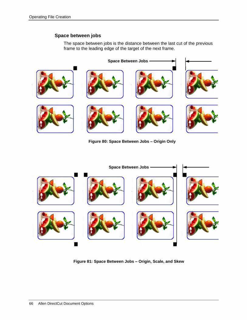
Operating File Creation
66 Allen DirectCut Document Options
Space between jobs
The space between jobs is the distance between the last cut of the previous frame to the leading edge of the target of the next frame.
Figure 81: Space Between Jobs – Origin, Scale, and Skew
Space Between Jobs
Figure 80: Space Between Jobs – Origin Only
Space Between Jobs
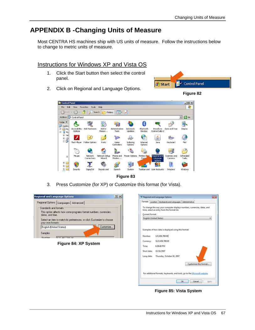
Changing Units of Measure
Instructions for Windows XP and Vista OS 67
APPENDIX B - Changing Units of Measure
Most CENTRA HS machines ship with US units of measure. Follow the instructions below to change to metric units of measure.
Instructions for Windows XP and Vista OS
1. Click the Start button then select the control panel.
2. Click on Regional and Language Options.
3. Press Customize (for XP) or Customize this format (for Vista).
Figure 84: XP System
Figure 82
Figure 83
Figure 85: Vista System

Changing Units of Measure
68 Instructions for Windows XP and Vista OS
4. Click on arrow to display Metric or US Measurement System.
5. Select desired measurement system.
6. Click Apply, then click OK, and then click Apply and OK on the next dialog box.
Figure 87: Vista System Figure 86: XP System
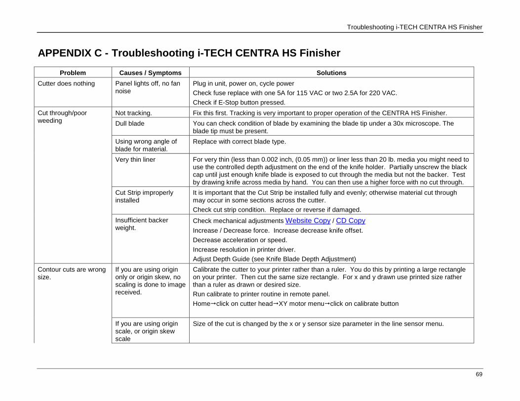
Troubleshooting i-TECH CENTRA HS Finisher
69
APPENDIX C - Troubleshooting i-TECH CENTRA HS Finisher
Problem Causes / Symptoms Solutions
Cutter does nothing Panel lights off, no fan noise
Plug in unit, power on, cycle power
Check fuse replace with one 5A for 115 VAC or two 2.5A for 220 VAC.
Check if E-Stop button pressed.
Cut through/poor weeding
Not tracking. Fix this first. Tracking is very important to proper operation of the CENTRA HS Finisher.
Dull blade You can check condition of blade by examining the blade tip under a 30x microscope. The blade tip must be present.
Using wrong angle of blade for material.
Replace with correct blade type.
Very thin liner For very thin (less than 0.002 inch, (0.05 mm)) or liner less than 20 lb. media you might need to use the controlled depth adjustment on the end of the knife holder. Partially unscrew the black cap until just enough knife blade is exposed to cut through the media but not the backer. Test by drawing knife across media by hand. You can then use a higher force with no cut through.
Cut Strip improperly installed
It is important that the Cut Strip be installed fully and evenly; otherwise material cut through may occur in some sections across the cutter.
Check cut strip condition. Replace or reverse if damaged.
Insufficient backer weight.
Check mechanical adjustments Website Copy / CD Copy
Increase / Decrease force. Increase decrease knife offset.
Decrease acceleration or speed.
Increase resolution in printer driver.
Adjust Depth Guide (see Knife Blade Depth Adjustment)
Contour cuts are wrong size.
If you are using origin only or origin skew, no scaling is done to image received.
Calibrate the cutter to your printer rather than a ruler. You do this by printing a large rectangle on your printer. Then cut the same size rectangle. For x and y drawn use printed size rather than a ruler as drawn or desired size.
Run calibrate to printer routine in remote panel.
Homeclick on cutter headXY motor menuclick on calibrate button
If you are using origin scale, or origin skew scale
Size of the cut is changed by the x or y sensor size parameter in the line sensor menu.

Troubleshooting i-TECH CENTRA HS Finisher
70
Problem Causes / Symptoms Solutions
See SmartMarkTM
setup in Appendix A
Labels or contour cuts are cutting in the wrong spot
Verify you created job correctly.
Origin Target is at minimum x and minimum y of drawing.
The scan area contains only target and background with no stray marks that could be seen as targets.
Verify printer properties are correct
Rotation is set correctly. Target cut should be in same corner (upper right) on preview as selected origin corner.
Find origin property is set to Origin only.
Verify sensor settings have not been lost
In the remote panel select home click on cutter head click on SmartMark™ “button” select x sensor offset, y sensor offset, scan length.
If your job is off by only a little bit (less than 1/8 inch (3mm)) and is same for every frame you can measure this error and correct your x and y sensor offset by the amount of the error you measure.
Verify scan length is the same as the length of the size of the target
Verify the scan offsets = ½ of the length of the size of the target
Adjust Scan Velocity.
Verify the space between jobs in the line sensor menu is zero.
Target errors tar1, tar2, tar3, tar4
These errors indicate that the target scanner did not find the target.
If tar1 on first frame:
Verify red led is lit.
Verify that you positioned red led pointer to right rear corner of target
Check that distance led is from media is 3.4 to 4.6 mm.
Run line sensor diagnostic (21) to verify operation of sensor.
If tar1 on 2nd or subsequent frame
Verify space between jobs in printer driver is set correctly. If it is set correctly after cutting first frame, the knife blade should be on the leading edge of the target of the next frame.
Tar2 – 4. Verify job you are sending matches job you printed
Verify rotation is correct in printer driver
Verify job is built correctly in that scale and skew target print is in same location is die lines for scale and skew target.
Verify scale and skew targets are at extents of image. Skew should be a minimum x and
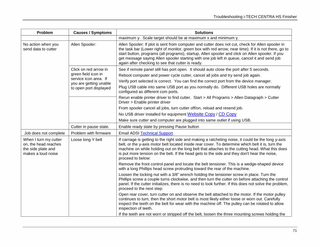
Troubleshooting i-TECH CENTRA HS Finisher
71
Problem Causes / Symptoms Solutions
maximum y. Scale target should be at maximum x and minimum y.
No action when you send data to cutter
Allen Spooler: Allen Spooler: If plot is sent from computer and cutter does not cut, check for Allen spooler in the task bar (Lower right of monitor, green box with red arrow, near time). If it is not there, go to start button, programs (all programs), startup, Allen spooler and click on Allen spooler. If you get message saying Allen spooler starting with one job left in queue, cancel it and send job again after checking to see that cutter is ready.
Click on red arrow in green field icon in service icon area. If you are getting unable to open port displayed
See if remote panel still has port open. It should auto close the port after 5 seconds.
Reboot computer and power cycle cutter, cancel all jobs and try send job again.
Verify port selected is correct. You can find the correct port from the device manager.
Plug USB cable into same USB port as you normally do. Different USB holes are normally configured as different com ports.
Rerun enable printer driver to find cutter. Start > All Programs > Allen Datagraph > Cutter Driver > Enable printer driver
From spooler cancel all jobs, turn cutter off/on, reload and resend job.
No USB driver installed for equipment Website Copy / CD Copy
Make sure cutter and computer are plugged into same outlet if using USB.
Cutter in pause state. Enable ready state by pressing Pause button
Job does not complete Problem with firmware Email ADSI Technical Support
When I turn my cutter on, the head reaches the side plate and makes a loud noise
Loose long Y belt
If carriage is getting to the right side and making a ratcheting noise, it could be the long y-axis belt, or the y-axis motor belt located inside rear cover. To determine which belt it is, turn the machine on while holding out on the long belt that attaches to the cutting head. What this does is put more tension on the belt. If the head gets to the side and they don't hear the noise, proceed to below:
Remove the front control panel and locate the belt tensioner. This is a wedge-shaped device with a long Phillips head screw protruding toward the rear of the machine.
Loosen the locking nut with a 3/8" wrench holding the tensioner screw in place. Turn the Phillips screw a couple turns clockwise, and then turn the cutter on before attaching the control panel. If the cutter initializes, there is no need to look further. If this does not solve the problem, proceed to the next step:
Open rear cover, turn cutter on and observe the belt attached to the motor. If the motor pulley continues to turn, then the short motor belt is most likely either loose or worn out. Carefully inspect the teeth on the belt for wear with the machine off. The pulley can be rotated to allow inspection of teeth.
If the teeth are not worn or stripped off the belt, loosen the three mounting screws holding the
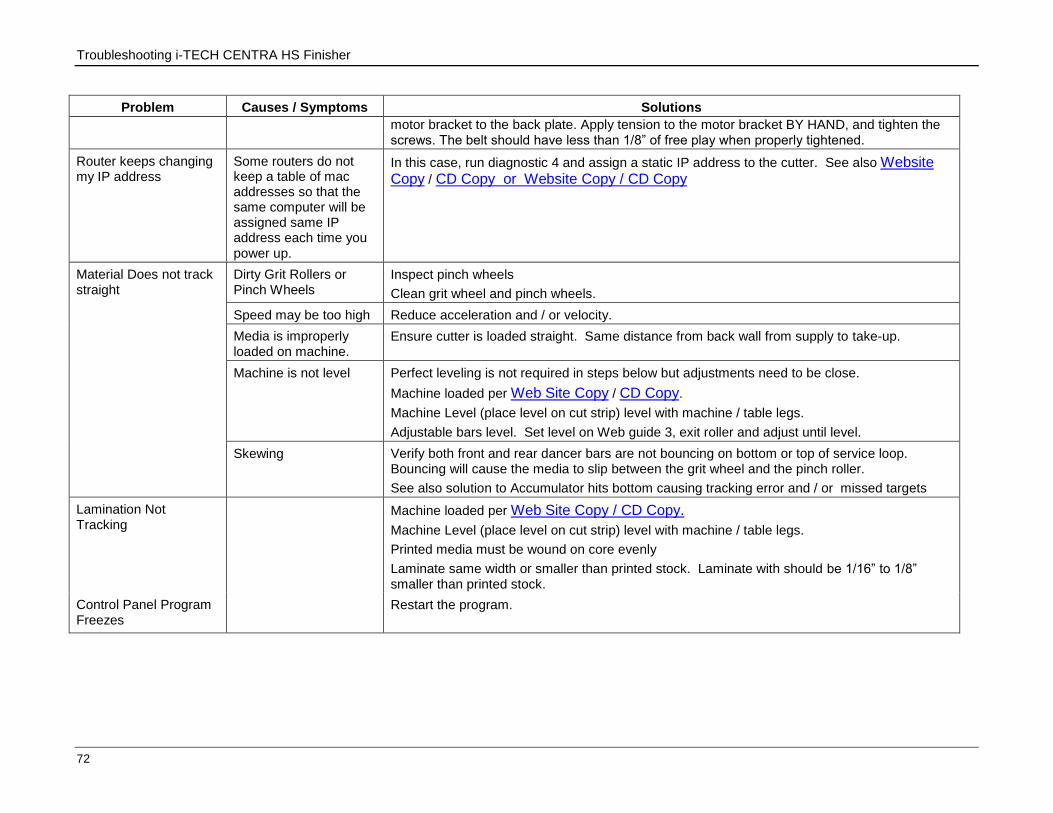
Troubleshooting i-TECH CENTRA HS Finisher
72
Problem Causes / Symptoms Solutions
motor bracket to the back plate. Apply tension to the motor bracket BY HAND, and tighten the screws. The belt should have less than 1/8” of free play when properly tightened.
Router keeps changing my IP address
Some routers do not keep a table of mac addresses so that the same computer will be assigned same IP address each time you power up.
In this case, run diagnostic 4 and assign a static IP address to the cutter. See also Website Copy / CD Copy or Website Copy / CD Copy
Material Does not track straight
Dirty Grit Rollers or Pinch Wheels
Inspect pinch wheels
Clean grit wheel and pinch wheels.
Speed may be too high Reduce acceleration and / or velocity.
Media is improperly loaded on machine.
Ensure cutter is loaded straight. Same distance from back wall from supply to take-up.
Machine is not level Perfect leveling is not required in steps below but adjustments need to be close.
Machine loaded per Web Site Copy / CD Copy.
Machine Level (place level on cut strip) level with machine / table legs.
Adjustable bars level. Set level on Web guide 3, exit roller and adjust until level.
Skewing
Verify both front and rear dancer bars are not bouncing on bottom or top of service loop. Bouncing will cause the media to slip between the grit wheel and the pinch roller.
See also solution to Accumulator hits bottom causing tracking error and / or missed targets
Lamination Not Tracking
Machine loaded per Web Site Copy / CD Copy.
Machine Level (place level on cut strip) level with machine / table legs.
Printed media must be wound on core evenly
Laminate same width or smaller than printed stock. Laminate with should be 1/16” to 1/8” smaller than printed stock.
Control Panel Program Freezes
Restart the program.

Connect HS to Local Network
73
APPENDIX D - Connect HS to Local Network
There are three (3) connecting options for using an Ethernet connection between the CENTRA HS cutter and a computer. The instructions below are followed by Figure 90 showing how the PC/Network/CENTRA are connected together.
Using Two Wall Jacks
Use this option when the PC and CENTRA HS location used for installation has two 2) wall jacks.
1. Connect the PC to one wall jack.
2. Connect the supplied Ethernet Cable to the HS Ethernet port on the rear of the machine and plug the opposite end into the second wall jack.
Using One Wall Jack
Use this option when the PC is already connected to the network via wall jack and there is no other jack available for the CENTRA HS. You will need to purchase an Ethernet Switch (10/100 3 or more ports) and an additional Ethernet cable.
1. Connect one end of the purchased cable to the uplink port of the Ethernet Switch and plug the other end into the wall jack.
2. Connect the computer to one of the other ports on the switch.
3. Connect the CENTRA HS to another port on the switch.
The cutter typically requires only a 10 mbs port, but the PC may need a larger capacity port. Purchase a switch that best meets the needs of your computer.
The cable required for this connection option should be a cat5e network cable for 10/100 mbs or a cat6 cable for 1000 mbs
Using a Crossover Cable
If the Ethernet port of the computer is not used to connect to the internet, it can be used to connect to the cutter.
1. Connect the supplied Ethernet Cable and Crossover Adapter together.
2. Plug one end into the Ethernet port of the computer and the other end into the Ethernet port of the cutter located on the right rear of the machine.
When using a crossover adapter, the computer must be set to a static IP address of 192.168.4.2 with a subnet mask of 255.255.255.0.
3. Set specified IP for PC as follows:

Connect HS to Local Network
74 Using a Crossover Cable
XP Instructions:
a) Start -> right click on My Network Places -> left click on properties
b) Right click on local area connection -> left click on properties
c) Select internet protocol (TCP/IP)
d) Click on properties button
e) Click on use the following IP address
f) Enter IP address and mask as shown in Figure 89.
g) Click OK.
Vista and Windows 7 Instructions:
a) Start -> right click on Network -> left click on Properties
b) Left click on manage network connections (Windows 7 - change adaptor settings)
c) Right click on local area connection -> left click on properties
d) Select internet protocol version 4 (TCP/IPv4)
e) Click on properties button
f) Click on use the following IP address
g) Enter IP address and mask as shown in Figure 89.
h) Click OK.
Figure 89: Setting IP Address
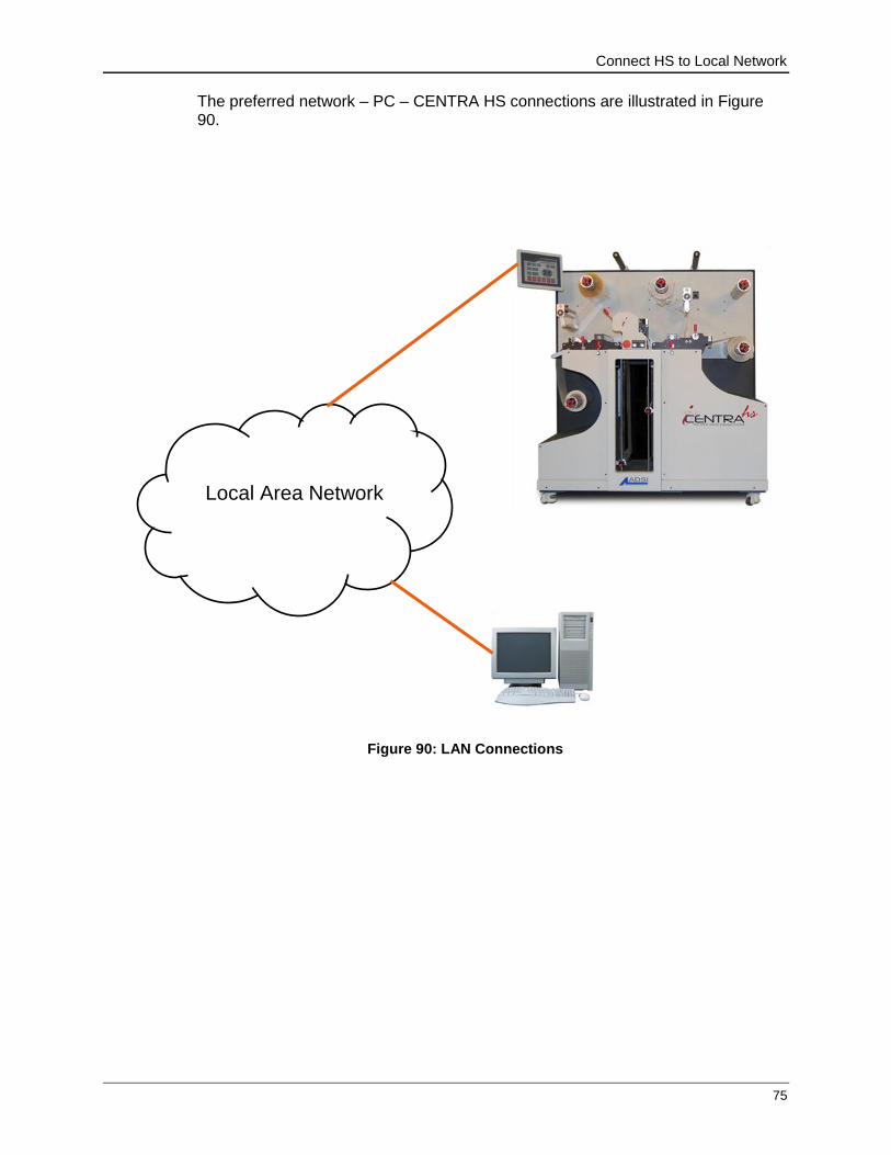
Connect HS to Local Network
75
The preferred network – PC – CENTRA HS connections are illustrated in Figure 90.
Local Area Network
Figure 90: LAN Connections

76 Using a Crossover Cable
APPENDIX E - Radio and Television Interference
This equipment has been tested and found to comply with the limits for a Class A digital device, pursuant to Part 15 of the FCC rules. These limits are designed to provide reasonable protection against harmful interference when the equipment is operated in a commercial environment. This equipment generates, uses and can radiate radio frequency energy and, if not installed and used in accordance with the instruction manual, may cause harmful interference to radio communications. Operation of this equipment in a residential area is likely to cause harmful interference in which case the user will be required to correct the interference at his own expense.
In order to maintain compliance with FCC regulations shielded cables must be used with this equipment. Operation with non-approved equipment or unshielded cables is likely to result in interference to radio & television reception.
This device complies with part 15 of FCC Rules. Operation is subject to the following two conditions; (1) This device may not cause harmful interference, and (2) this device must accept any interference received, including interference that may cause undesired operation.

Advanced Menus and Control Panel Options
Changing Control Panel Starting Defaults 77
APPENDIX F - Advanced Menus and Control Panel Options
This appendix contains instructions for setting or making common adjustments to the CENTRA HS. Some menus are only available while operating in the “Advanced” menu mode. Component specific menus may be accessed on the Home page by clicking inside the red circle located at the component.
Changing Menu Mode
The Control Panel has three (3) available operating menu modes. They are “Normal”, “Advanced” and “All” (Diagnostic).
1. Go to the Home page then click on the red circle at the cutter head.
2. When the Cutter Menu appears click on the “Software” button.
3. Click on the Advanced Menus button when the Software menu appears.
4. Select “Normal”, “Advanced”, or “All” at the next screen. The screen returns to the Software menu page.
Only menus associated with the current menu mode will display in the control panel.
Changing Control Panel Starting Defaults
When the CENTRA is powered up, it uses the values contained in setup 1 as the default starting values. Follow the steps below to change the default start settings for the control panel.
1. Navigate to the Home page and select the red circle around the cutter.
2. Click on the Software button
3. Click on Settings Menu button
4. Make desired changes to the available parameters
5. Click on Setup Number, enter “1” and click on Save button.
6. Click “Save Setup” button.
Changing the force on the Centra HS Controls page changes the power up default force setting.
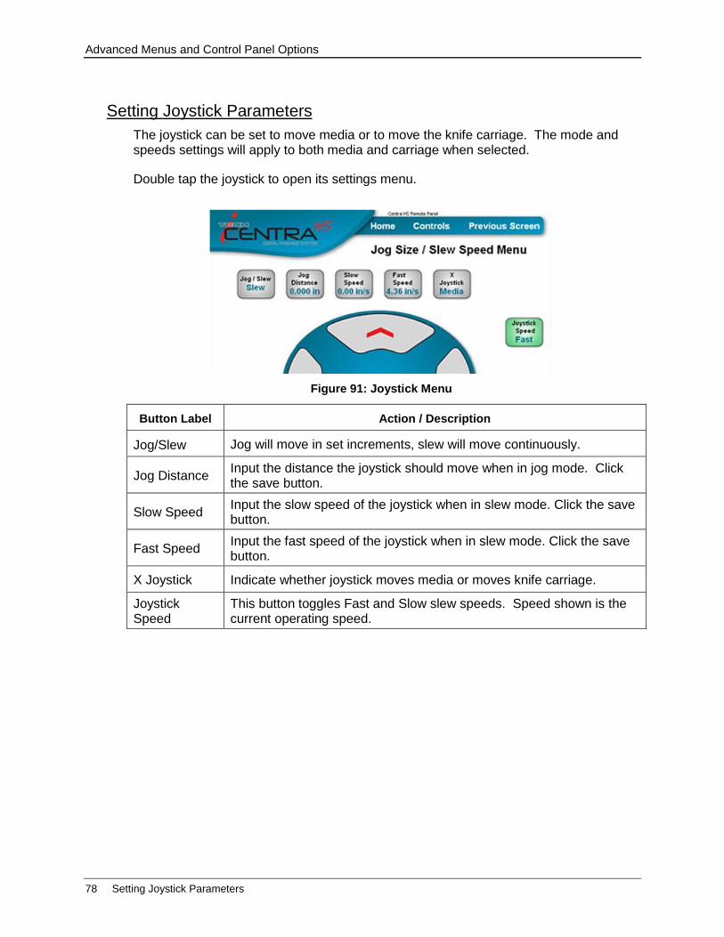
Advanced Menus and Control Panel Options
78 Setting Joystick Parameters
Setting Joystick Parameters
The joystick can be set to move media or to move the knife carriage. The mode and speeds settings will apply to both media and carriage when selected.
Double tap the joystick to open its settings menu.
Button Label Action / Description
Jog/Slew Jog will move in set increments, slew will move continuously.
Jog Distance Input the distance the joystick should move when in jog mode. Click the save button.
Slow Speed Input the slow speed of the joystick when in slew mode. Click the save button.
Fast Speed Input the fast speed of the joystick when in slew mode. Click the save button.
X Joystick Indicate whether joystick moves media or moves knife carriage.
Joystick Speed
This button toggles Fast and Slow slew speeds. Speed shown is the current operating speed.
Figure 91: Joystick Menu
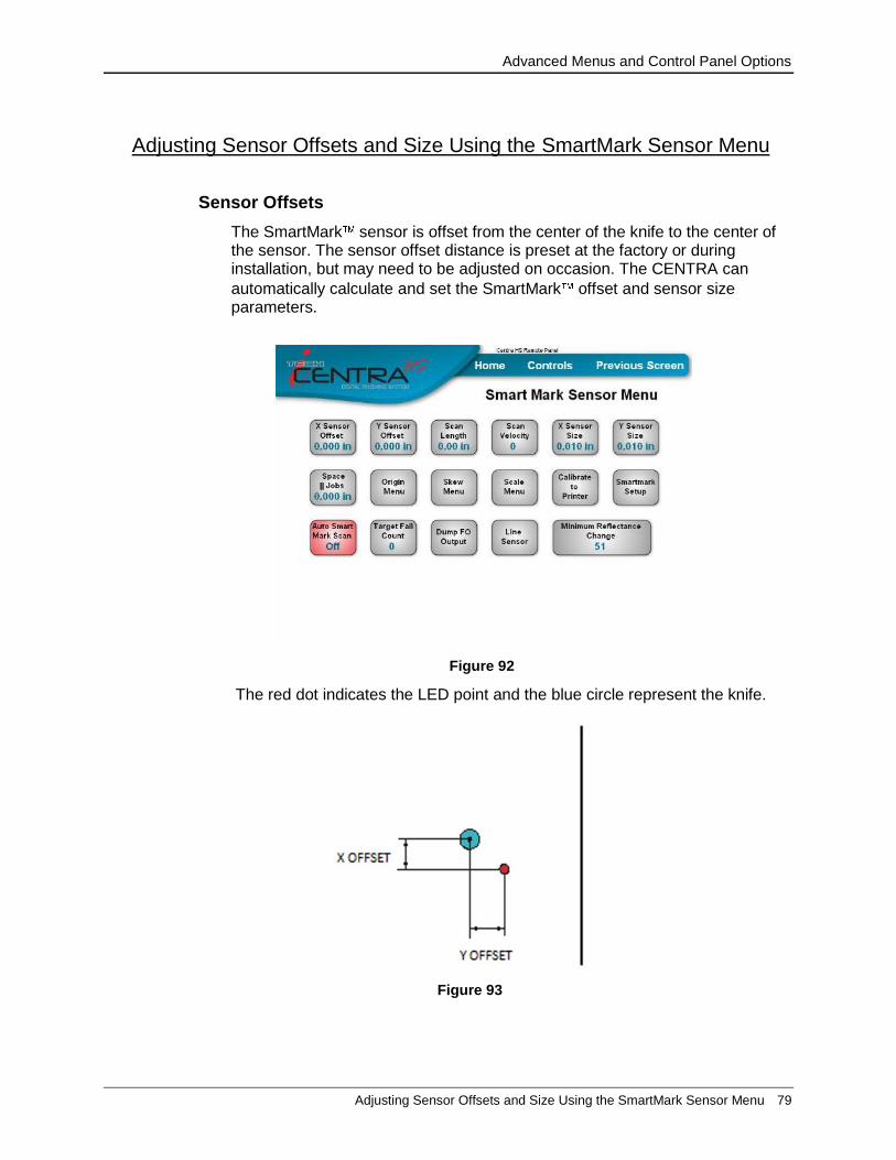
Advanced Menus and Control Panel Options
Adjusting Sensor Offsets and Size Using the SmartMark Sensor Menu 79
Adjusting Sensor Offsets and Size Using the SmartMark Sensor Menu
Sensor Offsets
The SmartMark sensor is offset from the center of the knife to the center of the sensor. The sensor offset distance is preset at the factory or during installation, but may need to be adjusted on occasion. The CENTRA can
automatically calculate and set the SmartMark offset and sensor size parameters.
The red dot indicates the LED point and the blue circle represent the knife.
Figure 93
Figure 92
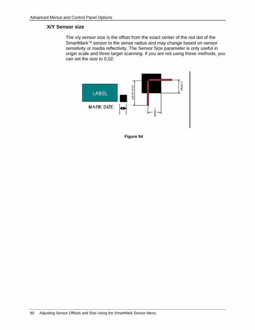
Advanced Menus and Control Panel Options
80 Adjusting Sensor Offsets and Size Using the SmartMark Sensor Menu
X/Y Sensor size
The x/y sensor size is the offset from the exact center of the red dot of the
SmartMark sensor to the sense radius and may change based on sensor sensitivity or media reflectivity. The Sensor Size parameter is only useful in origin scale and three target scanning. If you are not using these methods, you can set the size to 0.02.
Figure 94
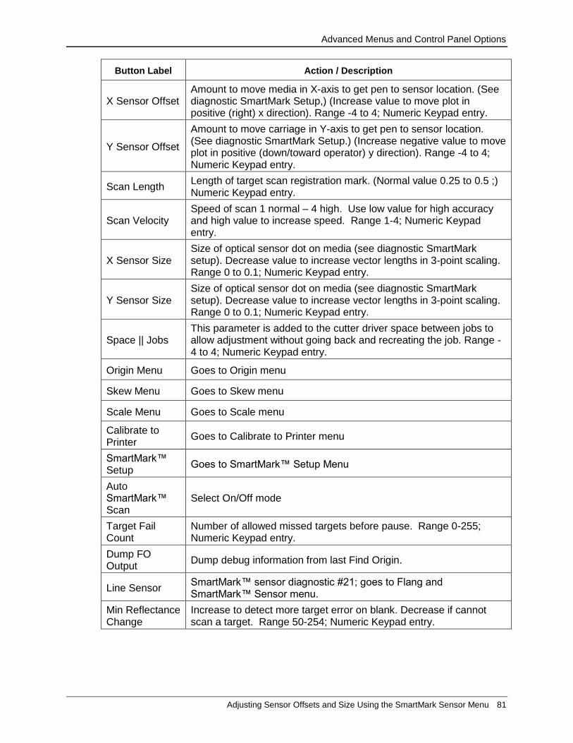
Advanced Menus and Control Panel Options
Adjusting Sensor Offsets and Size Using the SmartMark Sensor Menu 81
Button Label Action / Description
X Sensor Offset Amount to move media in X-axis to get pen to sensor location. (See diagnostic SmartMark Setup,) (Increase value to move plot in positive (right) x direction). Range -4 to 4; Numeric Keypad entry.
Y Sensor Offset
Amount to move carriage in Y-axis to get pen to sensor location. (See diagnostic SmartMark Setup.) (Increase negative value to move plot in positive (down/toward operator) y direction). Range -4 to 4; Numeric Keypad entry.
Scan Length Length of target scan registration mark. (Normal value 0.25 to 0.5 ;) Numeric Keypad entry.
Scan Velocity Speed of scan 1 normal – 4 high. Use low value for high accuracy and high value to increase speed. Range 1-4; Numeric Keypad entry.
X Sensor Size Size of optical sensor dot on media (see diagnostic SmartMark setup). Decrease value to increase vector lengths in 3-point scaling. Range 0 to 0.1; Numeric Keypad entry.
Y Sensor Size Size of optical sensor dot on media (see diagnostic SmartMark setup). Decrease value to increase vector lengths in 3-point scaling. Range 0 to 0.1; Numeric Keypad entry.
Space || Jobs This parameter is added to the cutter driver space between jobs to allow adjustment without going back and recreating the job. Range -4 to 4; Numeric Keypad entry.
Origin Menu Goes to Origin menu
Skew Menu Goes to Skew menu
Scale Menu Goes to Scale menu
Calibrate to Printer
Goes to Calibrate to Printer menu
SmartMark™ Setup
Goes to SmartMark™ Setup Menu
Auto SmartMark™ Scan
Select On/Off mode
Target Fail Count
Number of allowed missed targets before pause. Range 0-255; Numeric Keypad entry.
Dump FO Output
Dump debug information from last Find Origin.
Line Sensor SmartMark™ sensor diagnostic #21; goes to Flang and SmartMark™ Sensor menu.
Min Reflectance Change
Increase to detect more target error on blank. Decrease if cannot scan a target. Range 50-254; Numeric Keypad entry.

Advanced Menus and Control Panel Options
82 Calibration
Calibration
Calibration is achieved by comparing the size of actual cuts in the media (Calibration Square Output) with the size input to the cutter itself or to a printed image.
XY Motor Calibration
This calibration menu is used to calibrate the cutter to real world sizes.
Button Label Action / Description
X Drawn This is the intended size of the rectangle you have drawn from left to right as you look at the machine. Range 5-49; Numeric Keypad entry.
Y Drawn This is the size intended of the rectangle you have drawn from front to back as you look at the machine. Range 5-15; Numeric Keypad entry.
X Measured This is the actual measured size of the rectangle you have cut from left to right as you look at the machine. Range 5-49; Numeric Keypad entry.
Y Measure This is the actual measured size of the rectangle you have cut from front to back as you look at the machine. Range 5-15; Numeric Keypad entry.
Current Calibration
No info**
Current cal factor compared to factory specifications
Update Update calibration in cutter.
To access this menu go to the Home page and click on the “By Function” button. Click “Customer Diagnostic”, and then “Calibrate”.
Figure 95

Advanced Menus and Control Panel Options
Calibration 83
Calibrate the cutter to actual cut size as follows:
1. Go to the home page and click on the “By Function” button then click on the “Customer Diagnostic” button.
2. Press the “Calibration Square Output” button.
3. Enter the desired cut size for the X and Y-axis. (E.g., entering 6 for both will tell the machine to cut a 6 x 6 square.)
4. Press “Cut Rectangle”.
5. The machine will cut a square in the media.
6. Measure the cut and note the exact measurements.
7. Return to the Customer Diagnostic Menu and press the “Calibrate” button.
8. Click on the “Printed X/Y Size buttons and enter the desired cut size for x and y.
9. Click on the “Cut X/Y Size” buttons and enter the actual size measured from the cut media.
10. Press the “Update” button. The computer will calculate any differences and display it as a percentage. If the percentage is >3% confirm all values are correctly keyed in. If incorrect, click no and start again.
11. Click yes to accept the calibration change.
12. Verify the calibration by returning to the “Customer Diagnostic” menu and making another cut in the media using the “Calibration Square Output” button.

Advanced Menus and Control Panel Options
84 Calibration
Calibrate To Printer
This calibration menu is used to calibrate the cutter to printed image sizes.
Button Label Action / Description
Printed X Size This is the intended size of the printed rectangle along the media movement of the roll. Range 5-49; Numeric Keypad entry.
Printed Y Size This is the intended size of the printed rectangle across the web. Range 5-15; Numeric Keypad entry.
Cut X Size This is the measured size of the printed rectangle you have cut from left to right as you look at the machine. Range 5-49; Numeric Keypad entry.
Cut Y Size This is the measured size of the printed rectangle you have cut from front to back as you look at the machine Range 5-15; Numeric Keypad entry.
Current Calibration
Current (x, y) cal factor.
Update Update calibration in cutter
To access this menu go to the Home page and click on the “By Function” button. Click “Customer Diagnostic”, and then “Calibrate to Printer”.
Figure 96

Advanced Menus and Control Panel Options
Calibration 85
Calibrate the cutter to print size as follows:
1. Measure the printed image and note the exact x and y sizes.
2. Press the “Calibration Square Output” button.
3. Enter the actual X and Y-axis size of the print. (E.g., entering 6 for both will tell the machine to cut a 6 x 6 square.)
4. Press “Cut Rectangle”.
5. The machine will cut a square in the media.
6. Measure the cut and note its exact measurements.
7. Return to the Customer Diagnostic Menu and press the “Calibrate to Printer” button.
8. Click on the “Printed X/Y Size buttons and enter the printed size for x and y.
9. Click on the “Cut X/Y Size” buttons and enter the actual size measured from the cut media.
10. Press the “Update” button. The computer will calculate any differences and display it as a percentage. If the percentage is >3% confirm all values are correctly keyed in. If incorrect, click no and start again.
11. Click yes to accept the calibration change.
12. Verify the calibration by returning to the “Customer Diagnostic” menu and making another cut in the media using the “Calibration Square Output” button.
Default Calibration (Customer Diagnostic Menu)
This diagnostic sets the calibration constants back to the factory defaults prior to initial calibration. After running this diagnostic, you will have to restore the calibration constants. Diagnostic 08 should be avoided unless you have received an E37 error, which automatically runs this diagnostic.
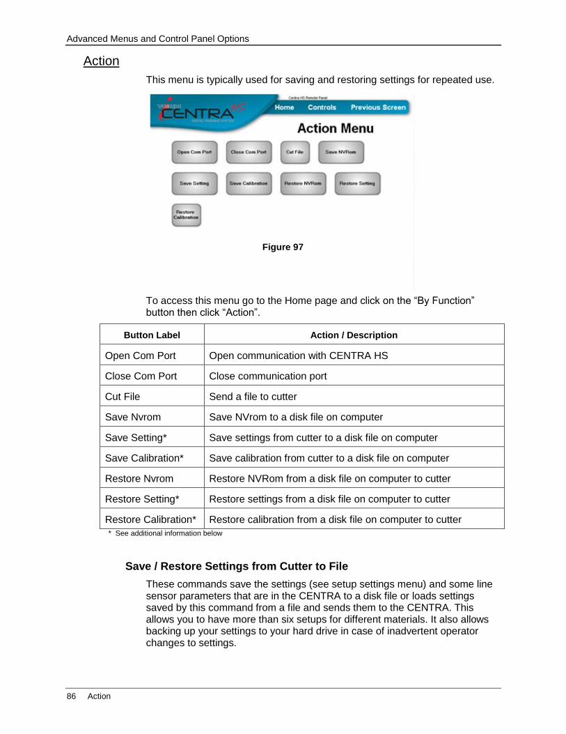
Advanced Menus and Control Panel Options
86 Action
Action
This menu is typically used for saving and restoring settings for repeated use.
To access this menu go to the Home page and click on the “By Function” button then click “Action”.
Button Label Action / Description
Open Com Port Open communication with CENTRA HS
Close Com Port Close communication port
Cut File Send a file to cutter
Save Nvrom Save NVrom to a disk file on computer
Save Setting* Save settings from cutter to a disk file on computer
Save Calibration* Save calibration from cutter to a disk file on computer
Restore Nvrom Restore NVRom from a disk file on computer to cutter
Restore Setting* Restore settings from a disk file on computer to cutter
Restore Calibration* Restore calibration from a disk file on computer to cutter
* See additional information below
Save / Restore Settings from Cutter to File
These commands save the settings (see setup settings menu) and some line sensor parameters that are in the CENTRA to a disk file or loads settings saved by this command from a file and sends them to the CENTRA. This allows you to have more than six setups for different materials. It also allows backing up your settings to your hard drive in case of inadvertent operator changes to settings.
Figure 97
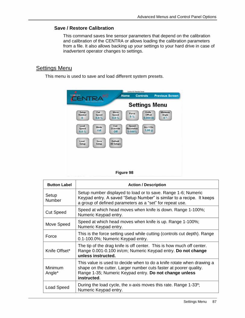
Advanced Menus and Control Panel Options
Settings Menu 87
Save / Restore Calibration
This command saves line sensor parameters that depend on the calibration and calibration of the CENTRA or allows loading the calibration parameters from a file. It also allows backing up your settings to your hard drive in case of inadvertent operator changes to settings.
Settings Menu
This menu is used to save and load different system presets.
Button Label Action / Description
Setup Number
Setup number displayed to load or to save. Range 1-6; Numeric Keypad entry. A saved “Setup Number” is similar to a recipe. It keeps a group of defined parameters as a “set” for repeat use.
Cut Speed Speed at which head moves when knife is down. Range 1-100%; Numeric Keypad entry.
Move Speed Speed at which head moves when knife is up. Range 1-100%; Numeric Keypad entry.
Force This is the force setting used while cutting (controls cut depth). Range 0.1-100.0%; Numeric Keypad entry.
Knife Offset* The tip of the drag knife is off center. This is how much off center. Range 0.001-0.100 in/cm; Numeric Keypad entry. Do not change unless instructed.
Minimum Angle*
This value is used to decide when to do a knife rotate when drawing a shape on the cutter. Larger number cuts faster at poorer quality. Range 1-35; Numeric Keypad entry. Do not change unless instructed.
Load Speed During the load cycle, the x-axis moves this rate. Range 1-33º; Numeric Keypad entry.
Figure 98
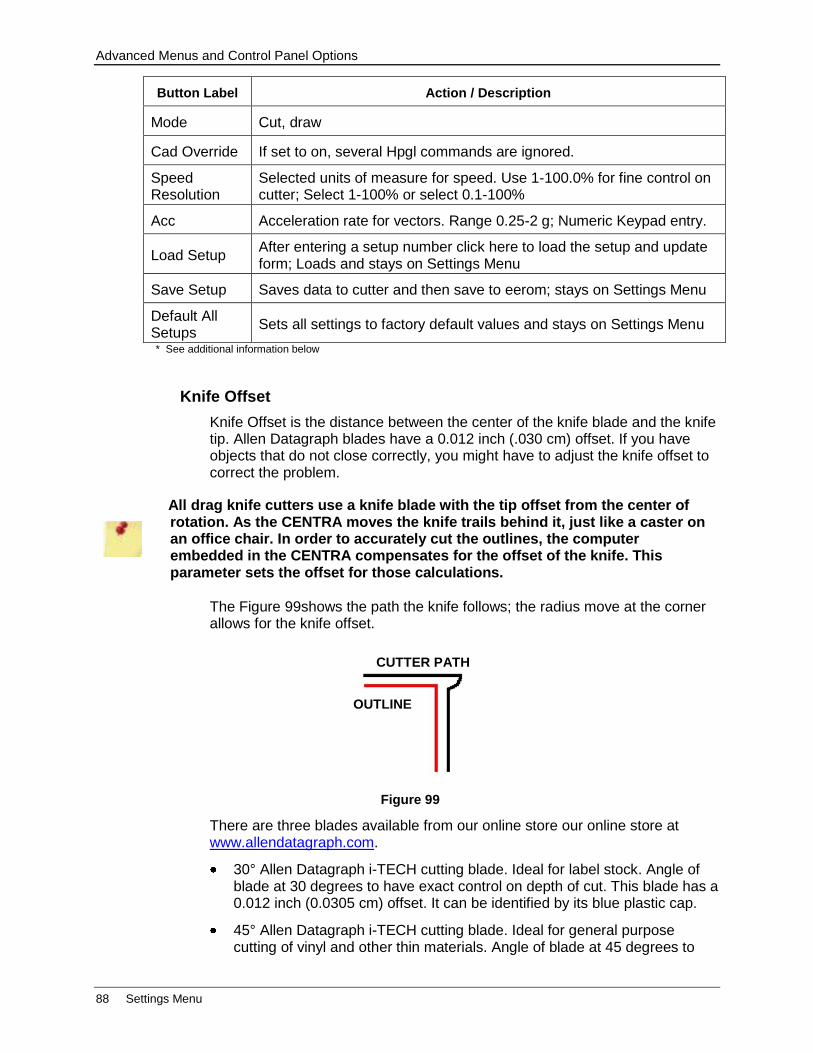
Advanced Menus and Control Panel Options
88 Settings Menu
Button Label Action / Description
Mode Cut, draw
Cad Override If set to on, several Hpgl commands are ignored.
Speed Resolution
Selected units of measure for speed. Use 1-100.0% for fine control on cutter; Select 1-100% or select 0.1-100%
Acc Acceleration rate for vectors. Range 0.25-2 g; Numeric Keypad entry.
Load Setup After entering a setup number click here to load the setup and update form; Loads and stays on Settings Menu
Save Setup Saves data to cutter and then save to eerom; stays on Settings Menu
Default All Setups
Sets all settings to factory default values and stays on Settings Menu
* See additional information below
Knife Offset
Knife Offset is the distance between the center of the knife blade and the knife tip. Allen Datagraph blades have a 0.012 inch (.030 cm) offset. If you have objects that do not close correctly, you might have to adjust the knife offset to correct the problem.
All drag knife cutters use a knife blade with the tip offset from the center of rotation. As the CENTRA moves the knife trails behind it, just like a caster on an office chair. In order to accurately cut the outlines, the computer embedded in the CENTRA compensates for the offset of the knife. This parameter sets the offset for those calculations.
The Figure 99shows the path the knife follows; the radius move at the corner allows for the knife offset.
There are three blades available from our online store our online store at www.allendatagraph.com.
30° Allen Datagraph i-TECH cutting blade. Ideal for label stock. Angle of blade at 30 degrees to have exact control on depth of cut. This blade has a 0.012 inch (0.0305 cm) offset. It can be identified by its blue plastic cap.
45° Allen Datagraph i-TECH cutting blade. Ideal for general purpose cutting of vinyl and other thin materials. Angle of blade at 45 degrees to
CUTTER PATH
OUTLINE
Figure 99
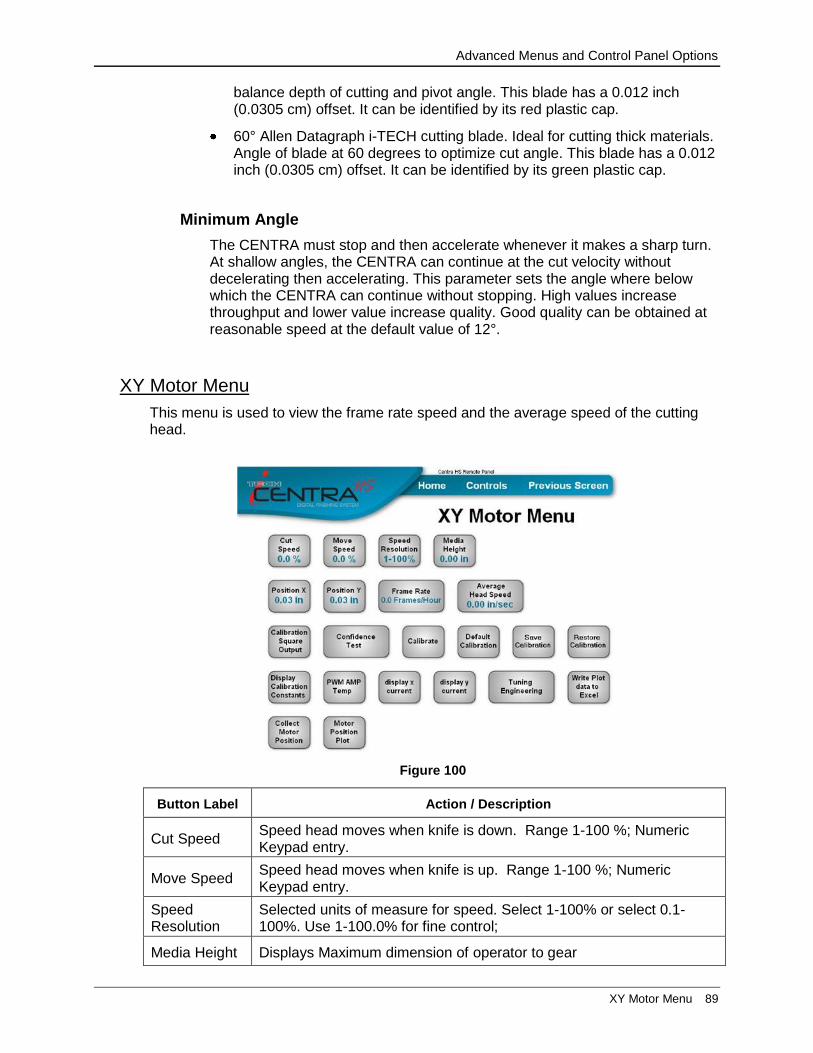
Advanced Menus and Control Panel Options
XY Motor Menu 89
balance depth of cutting and pivot angle. This blade has a 0.012 inch (0.0305 cm) offset. It can be identified by its red plastic cap.
60° Allen Datagraph i-TECH cutting blade. Ideal for cutting thick materials. Angle of blade at 60 degrees to optimize cut angle. This blade has a 0.012 inch (0.0305 cm) offset. It can be identified by its green plastic cap.
Minimum Angle
The CENTRA must stop and then accelerate whenever it makes a sharp turn. At shallow angles, the CENTRA can continue at the cut velocity without decelerating then accelerating. This parameter sets the angle where below which the CENTRA can continue without stopping. High values increase throughput and lower value increase quality. Good quality can be obtained at reasonable speed at the default value of 12°.
XY Motor Menu
This menu is used to view the frame rate speed and the average speed of the cutting head.
Button Label Action / Description
Cut Speed Speed head moves when knife is down. Range 1-100 %; Numeric Keypad entry.
Move Speed Speed head moves when knife is up. Range 1-100 %; Numeric Keypad entry.
Speed Resolution
Selected units of measure for speed. Select 1-100% or select 0.1-100%. Use 1-100.0% for fine control;
Media Height Displays Maximum dimension of operator to gear
Figure 100

Advanced Menus and Control Panel Options
90 XY Motor Menu
Button Label Action / Description
Position X Displays current position of cutting head
Position Y Displays current position of cutting head
Frame Rate Number of frames per hour for this job
Average Head Speed
Number of frames per hour for this job
Calibration Square Output
Goes to calibration square plot menu
Confidence Test
Start burn in with continuous confidence test
Calibrate Goes to xy motor calibration menu
Default Calibration
Displays default calibration warning dialog box
Save Calibration
Save calibration from cutter to disk file on computer
Restore Calibration
Restore calibration from a disk file on computer to cutter
Display Calibration Constants
Retrieve and display x/y position calibration to size scale factors
Pwm Amp Temp
Display temperature of PWM status
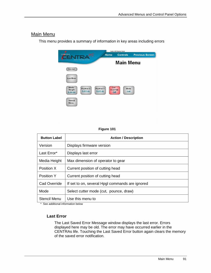
Advanced Menus and Control Panel Options
Main Menu 91
Main Menu
This menu provides a summary of information in key areas including errors
Button Label Action / Description
Version Displays firmware version
Last Error* Displays last error
Media Height Max dimension of operator to gear
Position X Current position of cutting head
Position Y Current position of cutting head
Cad Override If set to on, several Hpgl commands are ignored
Mode Select cutter mode (cut, pounce, draw)
Stencil Menu Use this menu to
* See additional information below
Last Error
The Last Saved Error Message window displays the last error. Errors displayed here may be old. The error may have occurred earlier in the CENTRAs life. Touching the Last Saved Error button again clears the memory of the saved error notification.
Figure 101
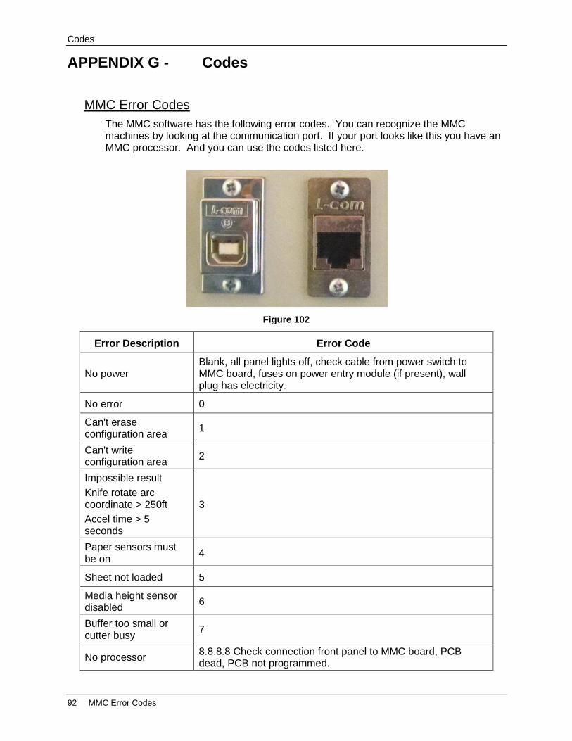
Codes
92 MMC Error Codes
APPENDIX G - Codes
MMC Error Codes
The MMC software has the following error codes. You can recognize the MMC machines by looking at the communication port. If your port looks like this you have an MMC processor. And you can use the codes listed here.
Error Description Error Code
No power Blank, all panel lights off, check cable from power switch to MMC board, fuses on power entry module (if present), wall plug has electricity.
No error 0
Can't erase configuration area
1
Can't write configuration area
2
Impossible result
Knife rotate arc coordinate > 250ft
Accel time > 5 seconds
3
Paper sensors must be on
4
Sheet not loaded 5
Media height sensor disabled
6
Buffer too small or cutter busy
7
No processor 8.8.8.8 Check connection front panel to MMC board, PCB dead, PCB not programmed.
Figure 102

Codes
MMC Error Codes 93
Error Description Error Code
Waiting for first vector to complete
9
Too much ambient light
10
Graphics or escape buffer overflow
12
Too many parameters in device control command
13
Invalid character in escape command
14
Escape command not implemented
15
Device control parameter out of limits
16
Dspic adc failed 20 - The motor current sensor on the dspic is not working. As this is a non-critical error this error just displays for 2 seconds and goes away.
X axis motor current above sensor capability.
21 - Most likely cause short in cable or sensor failure
Y axis motor current above sensor capability.
22 - Most likely cause short in cable or sensor failure
Z axis motor current above sensor capability.
23 - Most likely cause short in cable or sensor failure
No media covering media sensors
30
Memory test during confidence test failed
31
Reed switch sensor malfunction
32 – D024. Or pinch wheel under carriage too close to side plate. Move pinch wheel away from side plate. See options menu to disable the media height sensor.
Bad front panel key received
36 – D031
Bad calibration constants
37 – Must run diagnostic D008, then calibrate cutter.
Hpgl compatible command parser error
40
Rs232 device overrun (pic18 to pic32)
56
Rs232 framing error (pic18 to pic32)
57
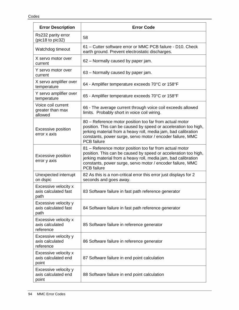
Codes
94 MMC Error Codes
Error Description Error Code
Rs232 parity error (pic18 to pic32)
58
Watchdog timeout 61 – Cutter software error or MMC PCB failure - D10. Check earth ground. Prevent electrostatic discharges.
X servo motor over current
62 – Normally caused by paper jam.
Y servo motor over current
63 – Normally caused by paper jam.
X servo amplifier over temperature
64 - Amplifier temperature exceeds 70°C or 158°F
Y servo amplifier over temperature
65 - Amplifier temperature exceeds 70°C or 158°F
Voice coil current greater than max allowed
66 - The average current through voice coil exceeds allowed limits. Probably short in voice coil wiring.
Excessive position error x axis
80 – Reference motor position too far from actual motor position. This can be caused by speed or acceleration too high, jerking material from a heavy roll, media jam, bad calibration constants, power surge, servo motor / encoder failure, MMC PCB failure
Excessive position error y axis
81 – Reference motor position too far from actual motor position. This can be caused by speed or acceleration too high, jerking material from a heavy roll, media jam, bad calibration constants, power surge, servo motor / encoder failure, MMC PCB failure
Unexpected interrupt on dspic
82 As this is a non-critical error this error just displays for 2 seconds and goes away.
Excessive velocity x axis calculated fast path
83 Software failure in fast path reference generator
Excessive velocity y axis calculated fast path
84 Software failure in fast path reference generator
Excessive velocity x axis calculated reference
85 Software failure in reference generator
Excessive velocity y axis calculated reference
86 Software failure in reference generator
Excessive velocity x axis calculated end point
87 Software failure in end point calculation
Excessive velocity y axis calculated end point
88 Software failure in end point calculation
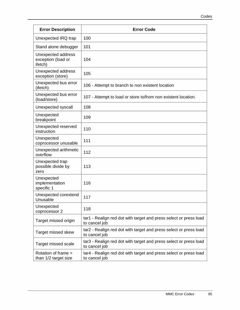
Codes
MMC Error Codes 95
Error Description Error Code
Unexpected IRQ trap 100
Stand alone debugger 101
Unexpected address exception (load or ifetch)
104
Unexpected address exception (store)
105
Unexpected bus error (ifetch)
106 - Attempt to branch to non existent location
Unexpected bus error (load/store)
107 - Attempt to load or store to/from non existent location.
Unexpected syscall 108
Unexpected breakpoint
109
Unexpected reserved instruction
110
Unexpected coprocessor unusable
111
Unexpected arithmetic overflow
112
Unexpected trap possible divide by zero
113
Unexpected implementation specific 1
116
Unexpected corextend Unusable
117
Unexpected coprocessor 2
118
Target missed origin tar1 - Realign red dot with target and press select or press load to cancel job
Target missed skew tar2 - Realign red dot with target and press select or press load to cancel job
Target missed scale tar3 - Realign red dot with target and press select or press load to cancel job
Rotation of frame > than 1/2 target size
tar4 - Realign red dot with target and press select or press load to cancel job

Codes
96 Boot Up / Self-test Codes
Boot Up / Self-test Codes
List of actions performed during boot up and self test. A display hanging on one of these codes may give indication of problem.
Boot "a" Codes Description of Action Occurring
a001 power up complete starting external ram test (boot flash)
a002 Init routines complete (pic32 initialized to run) (boot flash)
a003 power up complete (branch to main successful, now starting pic32 initialization) (application)
a004 init routines complete (pic32 initialized to run) (application)
a005 wait for first set, of reference (sending position info to dspic)
a006 await echo response (sending echo command to dspic and waiting for response)
a007 Wait for motors to stop moving (x/y motors now moving to home position)
a008 wait stop dac (home position found. stop motors)
a009 wait relax servo (send first vector to dspic to relax servo)
a010 Sending board rev to lan and usb processor
a011 wait for first front panel scan
a012 wait for eerom initialization
a013 wait for dfs init
a014 wait for no pounce mode
a015 wait for oigl_init
a016 wait for fpaninit
a017 wait for globufinit
a018 wait for initpen
a019 wait for initsvo
a020 wait for calibinit
a021 wait for set_not_ready
a022 wait for pid_init
a023 wait for reset servo bypass
a024 wait for enable servo interrupt
a025 wait for test diag mode
a026 wait for test frontpanel mode
a027 wait for initpos
a028 wait for load_settings
a029 wait for funca1
a030 eerominit starting
a031 eerominit starting pic18 init

Codes
Boot Up / Self-test Codes 97
Boot "a" Codes Description of Action Occurring
a032 eeromSendFlash erase pic18 nvrom. Can't erase configuration record to pic18 computer.
a033 eeromSendFlash program pic18nvrom. . Can't send configuration record to pic18 computer.
a034 eerominit diag08, 43, 48
a035 waiting for pic18 or usb processor to come out of reset
a036 waiting for dspic to come out of reset
a037 no firmware in pic 32 flash
a038 front panel button pressed during power up indicating request new firmware
a039 programming dspic
a040 programming pic18
a041 programming usb
a042 programming pic32
a043 programming complete (starting user program)
a045 eerominit call eerominit_checksum
a046 programming motamp
a061 download of xmodem record did not start with soh character (retry)
a062 download of xmodem record number incorrect (retry)
a063 download of xmodem record checksum did not match (retry)
a064 download of xmodem record short bytes (retry)
a065 download of xmodem record duplicate record ignored (retry ack)
a066 download of xmodem record ok
a067 download of file complete
a068 external ram test complete
a069 send to motamp initial motor data
should display d301 when 1st vector completes