Embed Size (px)
Citation preview

CENTRAL BATTERY SYSTEM: CBS
V. 09
Awex brand has been existing in the emergency lighting sector since 2002, invariably fulfilling its clearly defined mission: top-quality state-of-the-art products and customer satisfaction. We offer the full range of emergency lighting devices in compliance with all the European standards. Within 10 years of our market presence, we gained the leading position in the industry thanks to the involvement of knowledge, means, cooperation with best specialists, including research facilities, and investments in innovative projects. Awex means the latest technologies, experienced team of designers and engineers, top quality, reliable equipment, diversity of offer, unique design, unlimited productivity and unblemished reputation supported by references. The biggest award is satisfied and trusted customers. We also enjoy the recognition of independent experts. We were awarded the title of the “Export Leader 2006” for our business volume, and the Puls Biznesu awarded us twice with the “Business Gazelles” prize as one of the most dynamically developing companies in Poland.
Professional Personnel
We employ the best specialists in many different fields for whom we ensure constant improvement in qualifications by specialist trainings. The company’s design department provides flexible design of individual orders and the team of highly qualified engineers ensures continuous technological progress of offered equipment. The use of modern information flow methods within the company ensures that the offer and functionality of products is updated on an ongoing basis. The efficient project management allows building permanent and trust-based relationships with customers.
investments
We use the latest world technologies to guarantee quality, precise workmanship, optimised
technological process, and work ergonomics. We invest time and means so that every stage of manufacturing our products contributes to meeting any expectations of our customers.
tests
The research and development works ensure that our offer is constantly updated according to development trends in the industry, and thus we can supply the most modern, multifunctional and technologically advanced products.
We take care of the environment
We offer the environment-friendly products and the manufacturing process meets strict EU standards.
Quality Warranty
With the aim of fulfilling the company’s mission, we implemented the quality management system according to EN ISO 9001:2008, and the certificate issued by TÜV NORD ensures top quality of design, manufacture, assembly and servicing of emergency lighting equipment.

TABLE OF CONTENTS
central Battery system cBs 4Technology – SMART 5Switching Method And Revision Technology 5M-SL control module 6L-980 charger 8BST 980 booster 8ML 4x1A linear module 9ML 2x3A linear module 9ML 1x6A linear module 10ML-S 2x3A linear module 10ML-S 2x3A linear module 11HUB module 11LS-230 (POT) sensor module 12ELS–230 external module 12Event printer 14LS-24 (NP) sensor module 14ADS-20 address module 15ADS-Dali address module 16MP 500 switching module 17MP 4A switching module 18SD memory card 19CZF-01 phase loss sensor 19PZS module 20SMART server 20System structure 21Installation example 22Cabinet comparison 24
list of the fittings suitaBle for central Battery cBs 26
stanDarDs anD regulations 28
Scope of application 28Basic issues related to emergency lighting 29Escape route lighting 30Open area (anti-panic) lighting 30High risk task areas 30Arrangement of luminaires for evacuation lighting 31Safety signs 32Emergency lighting installations and systems 33Event log and testing of emergency lighting systems 33Emergency evacuation lighting equipment 35Classification of luminaires and protection classes 35Legal acts 37
4
Central Battery System: CBS
CENTRAL BATTERY SYSTEM: CBS
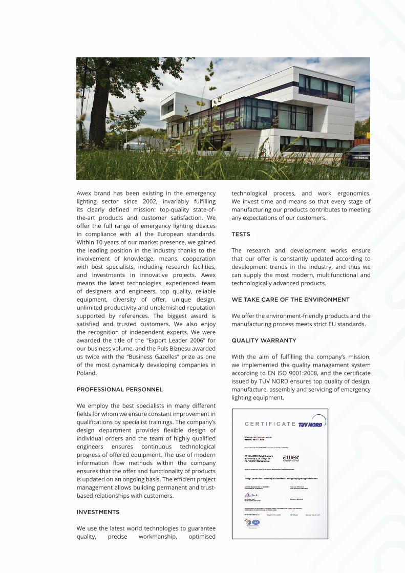
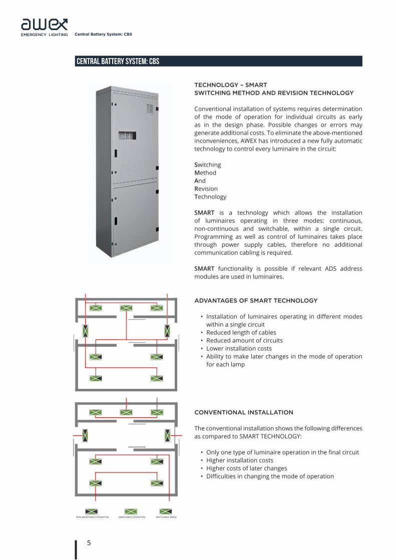
The CBS central power supply system is state-of-the-art, reliable and easy-to-operate central battery system constructed in accordance with the requirements of VDE 0108 as well as PN-EN 50171 and PN-EN 50172 standards.
The system is capable of monitoring circuits, luminaires and confi guration in mixed layout.
The CBS unit is equipped with a controller to supervise the operation of the entire system and archive any information on the occurred events and system condition. It has an intelligent charger to supervise the entire battery charge process and automatically stop the process in the event when battery is damaged.
Depending on the type of facility, it is possible to connect substations to diversify the central battery system functionalities, thus reducing the installation costs by shortening circuits with installed luminaires.
Damage to the central unit does not result in complete system failure, as substations take control of fi nal circuits and luminaires.
The SD card used in the system allows saving the periodic test results, event log and system confi guration. The above-mentioned information is stored in non-volatile memory of the controller.
• Modular system design – quick-assembly system• Freely programmable mode of operation for each
circuit (monitoring of circuits)• Freely programmable mode of operation for each
luminaire, regardless of the circuit • Monitoring of each luminaire and circuits• Ability to adjust the system to the layout of fi re
zones• Possible text description of each luminaire, circuit
and control• 4 keys with freely programmable functions• 4 keys with programmed functions• With shorting of any conductor to the protective
one, the battery supply operation is possible by use of separate AC and DC protections
CENTRAL BATTERY SYSTEM: CBS
5
Central Battery System: CBS
CENTRAL BATTERY SYSTEM: CBS
technology – smart sWitching methoD anD revision technology
Conventional installation of systems requires determination of the mode of operation for individual circuits as early as in the design phase. Possible changes or errors may generate additional costs. To eliminate the above-mentioned inconveniences, AWEX has introduced a new fully automatic technology to control every luminaire in the circuit:
SwitchingMethodAndRevisionTechnology
SMART is a technology which allows the installation of luminaires operating in three modes: continuous, non-continuous and switchable, within a single circuit. Programming as well as control of luminaires takes place through power supply cables, therefore no additional communication cabling is required.
SMART functionality is possible if relevant ADS address modules are used in luminaires.
MAINTEINED
NON-MAINTEINED
SWITCHING MODE
SWITCHING - DIMMING OPERATION*
aDvantages of smart technology
• Installation of luminaires operating in different modes within a single circuit
• Reduced length of cables• Reduced amount of circuits• Lower installation costs• Ability to make later changes in the mode of operation
for each lamp
conventional installation
The conventional installation shows the following differences as compared to SMART TECHNOLOGY:
• Only one type of luminaire operation in the final circuit• Higher installation costs• Higher costs of later changes• Difficulties in changing the mode of operation
NON-MAINTAINED OPERATION
MAINTAINED OPERATION
SWITCHABLE MODE
PRACA NA JASNO
PRACA NA CIEMNO
TRYB PRZEŁĄCZALNY
DS
PRACA NA JASNO
PRACA NA CIEMNO
TRYB PRZEŁĄCZALNY
Obwód 02Obwód 01
NON-MAINTAINED OPERATION MAINTAINED OPERATION SWITCHABLE MODE

6
Central Battery System: CBS
CENTRAL BATTERY SYSTEM: CBS
m-sl control moDule
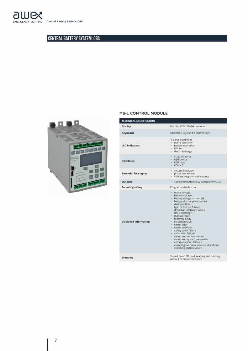
The control module is used to supervise and manage the operation of other modules included in the central battery. The keyboard and LCD display in front panel allow the user to configure and operate the whole system. System configuration may also be carried out using USB interface from PC with service application. Front panel LEDs allow the operating state of the central battery to be evaluated quickly. The module automatically supervises the following: mode of operation – mains/battery power supply, battery charging, system voltage, condition of insulation, protection against deep discharge. Detection of a failure or error is signalled at once and recorded in the event log. The occurrence of short-circuit or break in communication cables results in automatic switch of all circuits into mains power supply. In addition, the module allows automatic searching for and adding all the luminaires connected to the system. The controller allows upgrading firmware of any internal system modules as well as address modules.
Configuration:• 8 configuration keys• SD card• USB connector – service application
System control:• 4 potential-free 24V inputs, freely programmable, e.g.
functional test, battery test, sensor input etc• 4 function keys
• lock• start of functional test• start of battery test• reset of deep discharge error
• 4 keys with freely programmable functions:• Switching circuits on for AC power supply• Switching circuits on for DC power supply• Alarm reset: leakage• Alarm reset: failover• Functional test without warming up
• 3 LON communication buses• 2 timers• 3PH phase loss sensor connector• Remote system lock input
External communication:• Displaying the current system state
• LED indicators• LCD display
• BMS, website – LON1 bus• 3 potential free outputs – PZS or BMS
7
Central Battery System: CBS
CENTRAL BATTERY SYSTEM: CBS
TECHNICAL SPECIFICATION
Display Graphic LCD 128x64 resolution
Keyboard 8 function keys and 8 control keys
LED indicators
4 signalling diodes• mains operation• battery operation• failure• deep discharge
Interfaces
• SD/MMC cards• USB device• USB host• LON x 3
Potential free inputs • system blockade• phase loss sensor• 4 freely programmable inputs
Outputs • 4 programmable relay outputs 24V/0.5A
Sound signalling Programmable buzzer
Displayed information
• mains voltage• battery voltage• battery charge current (+)• battery discharge current (-)• date and time• type of test performed• disturbance/charge failure• deep discharge• manual reset• recovery delay• insulation fault• circuit fault• circuit overload• safety catch failure• substation failure• circuit and control names• circuit and system parameters• communication failures• event log overview, also in substations• switching station failure
Event log Stored on an SD card, reading and printing without dedicated software
ms-l control moDule

8
Central Battery System: CBS
CENTRAL BATTERY SYSTEM: CBS
l-980 charger
The charger module ensures battery charging based on UI characteristics with temperature compensation according to PN-EN 50-171. The charging algorithm executed by the charger is supervised by the control module. The charger is equipped with internal active PFC module, which provides power factor close to one (λ≈1). The charger is used for charging batteries with rated voltage of 216V. The maximum power of charger is 980W. If there is a need to charge a battery with higher capacity, the BST-980 charge boosters are used.
Features: • Charging the battery packs in accordance with
PN-EN 50-171• Operation with and control of BST-980 charge boosters• Monitoring of current leakage in final circuits• Protection against deep discharge• Ability to monitor battery voltage symmetry• Fan control• 3 measuring junctions for
• Voltage• Current• Temperature
External communication:• Displaying the current charger state• 4 potential-free outputs, freely programmable• Battery charge LED indicator• Service pin
TECHNICAL SPECIFICATION
Charge voltage Boost charge Float charge
265V DC246V DC
Maximum power ChargerCharge amplifier
980W ± 5%980W ± 5%
Maximum current ChargerCharge amplifier
4.5A ± 5%4.5A ± 5%
LED indicators (charger)
• battery charge level• battery failure• leakage failure• readiness• failure• status
Deep Discharge Protection 183.6V DC
Outputs 4 programmable relay outputs 24V/0.5A
Bst-980 Booster
9
Central Battery System: CBS
CENTRAL BATTERY SYSTEM: CBS
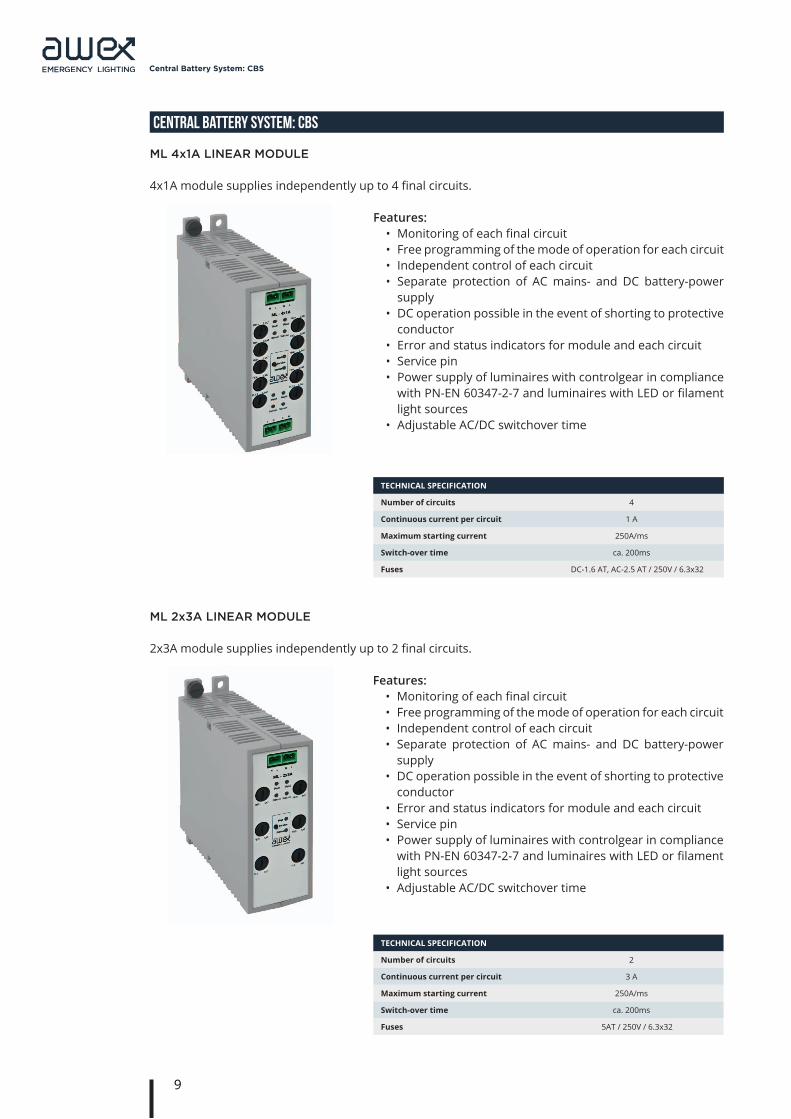
Features:• Monitoring of each final circuit• Free programming of the mode of operation for each circuit • Independent control of each circuit• Separate protection of AC mains- and DC battery-power
supply• DC operation possible in the event of shorting to protective
conductor• Error and status indicators for module and each circuit• Service pin• Power supply of luminaires with controlgear in compliance
with PN-EN 60347-2-7 and luminaires with LED or filament light sources
• Adjustable AC/DC switchover time
TECHNICAL SPECIFICATION
Number of circuits 4
Continuous current per circuit 1 A
Maximum starting current 250A/ms
Switch-over time ca. 200ms
Fuses DC-1.6 AT, AC-2.5 AT / 250V / 6.3x32
Features:• Monitoring of each final circuit• Free programming of the mode of operation for each circuit • Independent control of each circuit• Separate protection of AC mains- and DC battery-power
supply• DC operation possible in the event of shorting to protective
conductor• Error and status indicators for module and each circuit• Service pin• Power supply of luminaires with controlgear in compliance
with PN-EN 60347-2-7 and luminaires with LED or filament light sources
• Adjustable AC/DC switchover time
ml 2x3a linear moDule
2x3A module supplies independently up to 2 final circuits.
TECHNICAL SPECIFICATION
Number of circuits 2
Continuous current per circuit 3 A
Maximum starting current 250A/ms
Switch-over time ca. 200ms
Fuses 5AT / 250V / 6.3x32
ml 4x1a linear moDule
4x1A module supplies independently up to 4 final circuits.
10
Central Battery System: CBS
CENTRAL BATTERY SYSTEM: CBS
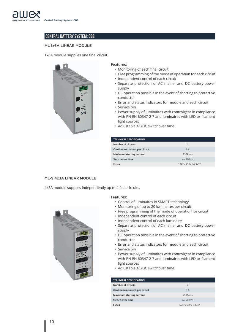
Features:• Monitoring of each final circuit• Free programming of the mode of operation for each circuit • Independent control of each circuit• Separate protection of AC mains- and DC battery-power
supply• DC operation possible in the event of shorting to protective
conductor• Error and status indicators for module and each circuit• Service pin• Power supply of luminaires with controlgear in compliance
with PN-EN 60347-2-7 and luminaires with LED or filament light sources
• Adjustable AC/DC switchover time
TECHNICAL SPECIFICATION
Number of circuits 1
Continuous current per circuit 6 A
Maximum starting current 250A/ms
Switch-over time ca. 200ms
Fuses 10AT / 250V / 6.3x32
Features:• Control of luminaires in SMART technology• Monitoring of up to 20 luminaires per circuit• Free programming of the mode of operation for circuit• Independent control of each circuit• Independent control of each luminaire• Separate protection of AC mains- and DC battery-power
supply• DC operation possible in the event of shorting to protective
conductor• Error and status indicators for module and each circuit• Service pin• Power supply of luminaires with controlgear in compliance
with PN-EN 60347-2-7 and luminaires with LED or filament light sources
• Adjustable AC/DC switchover time
TECHNICAL SPECIFICATION
Number of circuits 4
Continuous current per circuit 3 A
Maximum starting current 250A/ms
Switch-over time ca. 200ms
Fuses 5AT / 250V / 6,3x32
ml 1x6a linear moDule
1x6A module supplies one final circuit.
ml-s 4x3a linear moDule
4x3A module supplies independently up to 4 final circuits.
11
Central Battery System: CBS
CENTRAL BATTERY SYSTEM: CBS
Features:• Control of luminaires in SMART technology• Monitoring of up to 20 luminaires per circuit• Free programming of the mode of operation for circuit• Independent control of each circuit• Independent control of each luminaire• Separate protection of AC mains- and DC battery-power
supply• DC operation possible in the event of shorting to protective
conductor• Error and status indicators for module and each circuit• Service pin• Power supply of luminaires with controlgear in compliance
with PN-EN 60347-2-7 and luminaires with LED or filament light sources
• Adjustable AC/DC switchover time
TECHNICAL SPECIFICATION
Number of circuits 2
Continuous current per circuit 3 A
Maximum starting current 250A/ms
Switch-over time ca. 200ms
Fuses 5AT / 250V / 6.3x32
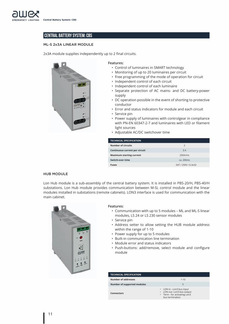
huB moDule
Lon Hub module is a sub-assembly of the central battery system. It is installed in PBS-20/H, PBS-40/H substations. Lon Hub module provides communication between M-SL control module and the linear modules installed in substations (remote cabinets). LON3 interface is used for communication with the main cabinet.
TECHNICAL SPECIFICATION
Number of addresses 1-10
Number of supported modules 5
Connectors
• LON in - Lon3 bus input• LON out- Lon3 bus output • Term - for activating Lon3
bus termination
Features:• Communication with up to 5 modules – ML and ML-S linear
modules, LS 24 or LS 230 sensor modules• Service pin• Address setter to allow setting the HUB module address
within the range of 1-10• Power supply for up to 5 modules• Built-in communication line termination• Module error and status indicators• Push-buttons: add/remove, select module and configure
module
ml-s 2x3a linear moDule
2x3A module supplies independently up to 2 final circuits.
12
Central Battery System: CBS
CENTRAL BATTERY SYSTEM: CBS
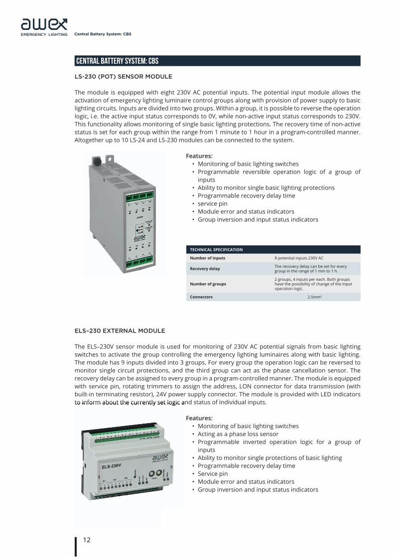
ls-230 (Pot) sensor moDule
The module is equipped with eight 230V AC potential inputs. The potential input module allows the activation of emergency lighting luminaire control groups along with provision of power supply to basic lighting circuits. Inputs are divided into two groups. Within a group, it is possible to reverse the operation logic, i.e. the active input status corresponds to 0V, while non-active input status corresponds to 230V. This functionality allows monitoring of single basic lighting protections. The recovery time of non-active status is set for each group within the range from 1 minute to 1 hour in a program-controlled manner. Altogether up to 10 LS-24 and LS-230 modules can be connected to the system.
TECHNICAL SPECIFICATION
Number of inputs 8 potential inputs 230V AC
Recovery delay The recovery delay can be set for every group in the range of 1 min to 1 h.
Number of groups2 groups, 4 inputs per each. Both groups have the possibility of change of the input operation logic.
Connectors 2.5mm2
Features:• Monitoring of basic lighting switches• Programmable reversible operation logic of a group of
inputs• Ability to monitor single basic lighting protections• Programmable recovery delay time• service pin• Module error and status indicators• Group inversion and input status indicators
els–230 eXternal moDule
The ELS–230V sensor module is used for monitoring of 230V AC potential signals from basic lighting switches to activate the group controlling the emergency lighting luminaires along with basic lighting. The module has 9 inputs divided into 3 groups. For every group the operation logic can be reversed to monitor single circuit protections, and the third group can act as the phase cancellation sensor. The recovery delay can be assigned to every group in a program-controlled manner. The module is equipped with service pin, rotating trimmers to assign the address, LON connector for data transmission (with built-in terminating resistor), 24V power supply connector. The module is provided with LED indicators to inform about the currently set logic and status of individual inputs.to inform about the currently set logic and status of individual inputs.
Features:• Monitoring of basic lighting switches• Acting as a phase loss sensor• Programmable inverted operation logic for a group of
inputs• Ability to monitor single protections of basic lighting• Programmable recovery delay time• Service pin• Module error and status indicators• Group inversion and input status indicators
13
Central Battery System: CBS
CENTRAL BATTERY SYSTEM: CBS
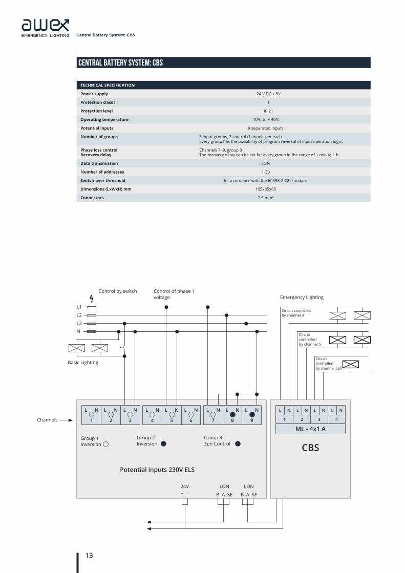
TECHNICAL SPECIFICATION
Power supply 24 V DC ± 5V
Protection class I I
Protection level IP 21
Operating temperature -10oC to + 40oC
Potential inputs 9 separated inputs
Number of groups 3 input groups, 3 control channels per each. Every group has the possibility of program reversal of input operation logic.
Phase loss control Recovery delay
Channels 7- 9, group 3The recovery delay can be set for every group in the range of 1 min to 1 h.
Data transmission LON
Number of addresses 1-30
Switch-over threshold In accordance with the 60598-2-22 standard
Dimensions (LxWxH) mm 105x85x60
Connectors 2.5 mm2
L N
1
L N
2
L N
3
L N
4
L N
5
L N
6
L N
7
L N
8
L N
9
Group 1Inversion
Group 2 Inversion
Group 3 3ph Control
Potential inputs 230V ELS
24V+ -
LON
B A SE
LON
B A SE
CBS
L N L N L N L N
1 2 3 4
ML - 4x1 A
Circuit controlled by channel 3ph
Circuit controlled by channel 5
Circuit controlled by channel 3
Channels
Basic Lighting
L1
L2
L3
N
Control by switch Control of phase 1 voltage Emergency Lighting
14
Central Battery System: CBS
CENTRAL BATTERY SYSTEM: CBS
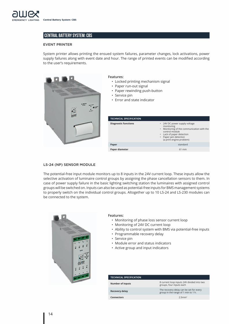
event Printer
System printer allows printing the ensued system failures, parameter changes, lock activations, power supply failures along with event date and hour. The range of printed events can be modified according to the user’s requirements.
TECHNICAL SPECIFICATION
Diagnostic functions • 24V DC power supply voltage monitoring
• Monitoring of the communication with the control module
• Lack of paper detection • Paper jam detection
(a print engine problem)
Paper standard
Paper diameter 61 mm
Features:• Locked printing mechanism signal• Paper run-out signal• Paper rewinding push-button• Service pin• Error and state indicator
ls-24 (nP) sensor moDule
The potential-free input module monitors up to 8 inputs in the 24V current loop. These inputs allow the selective activation of luminaire control groups by assigning the phase cancellation sensors to them. In case of power supply failure in the basic lighting switching station the luminaires with assigned control groups will be switched on. Inputs can also be used as potential-free inputs for BMS management systems to properly switch on the individual control groups. Altogether up to 10 LS-24 and LS-230 modules can be connected to the system.
TECHNICAL SPECIFICATION
Number of inputs 8 current loop inputs 24V divided into two groups, four inputs each
Recovery delay The recovery delay can be set for everygroup in the range of 1 min to 1 h.
Connectors 2.5mm2
Features:• Monitoring of phase loss sensor current loop• Monitoring of 24V DC current loop• Ability to control system with BMS via potential-free inputs• Programmable recovery delay • Service pin• Module error and status indicators• Active group and input indicators
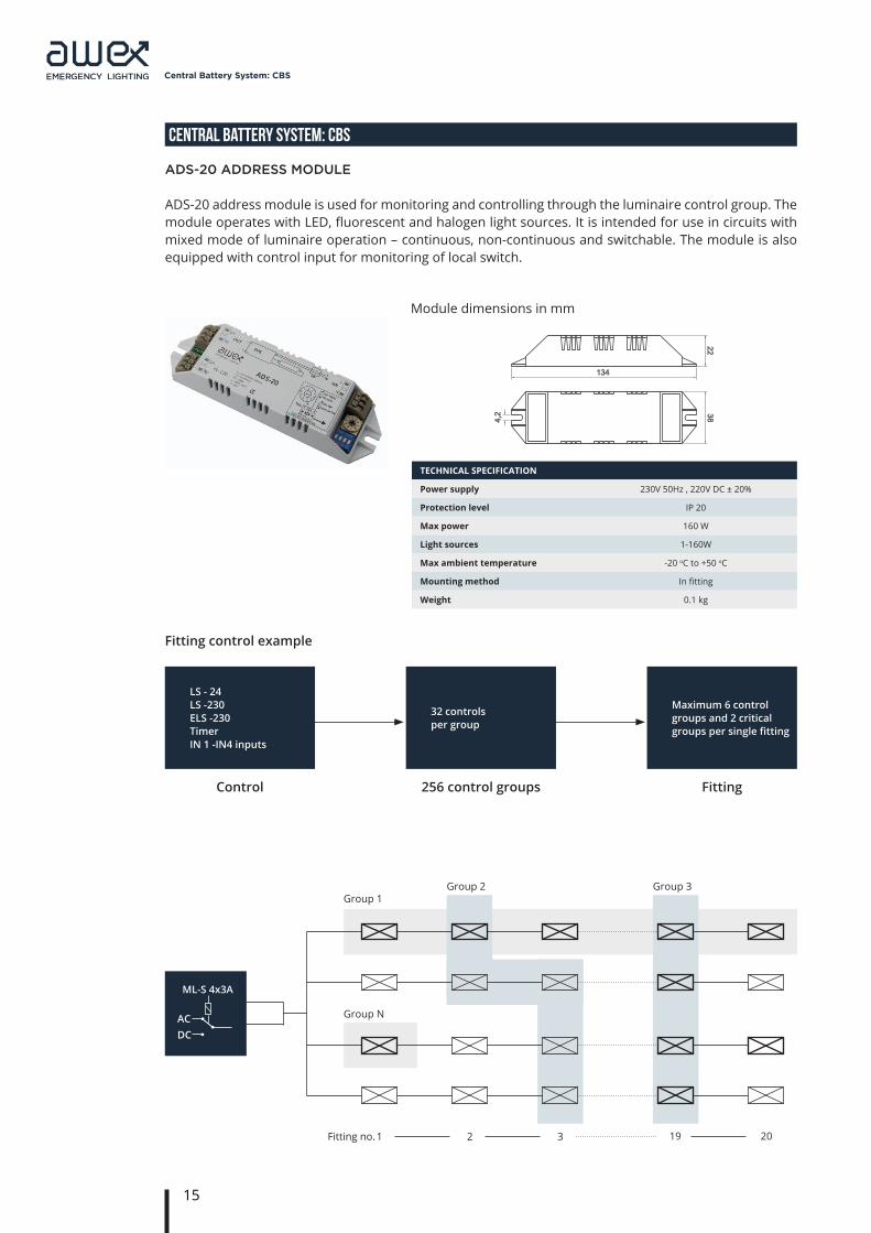
Control 256 control groups Fitting
Group 1
Group N
Group 2 Group 3
Fitting no.1 2 3 19 20
15
Central Battery System: CBS
CENTRAL BATTERY SYSTEM: CBS
aDs-20 aDDress moDule
ADS-20 address module is used for monitoring and controlling through the luminaire control group. The module operates with LED, fluorescent and halogen light sources. It is intended for use in circuits with mixed mode of luminaire operation – continuous, non-continuous and switchable. The module is also equipped with control input for monitoring of local switch.
TECHNICAL SPECIFICATION
Power supply 230V 50Hz , 220V DC ± 20%
Protection level IP 20
Max power 160 W
Light sources 1-160W
Max ambient temperature -20 oC to +50 oC
Mounting method In fitting
Weight 0.1 kg
LS - 24LS -230ELS -230TimerIN 1 -IN4 inputs
ML-S 4x3A
АCDC
32 controls per group
Maximum 6 control groups and 2 critical groups per single fitting
Fitting control example
Module dimensions in mm
134
22
38
4,2
18
,5
425
18
,5
157
157
4 418
7
21
15
16
Central Battery System: CBS
CENTRAL BATTERY SYSTEM: CBS
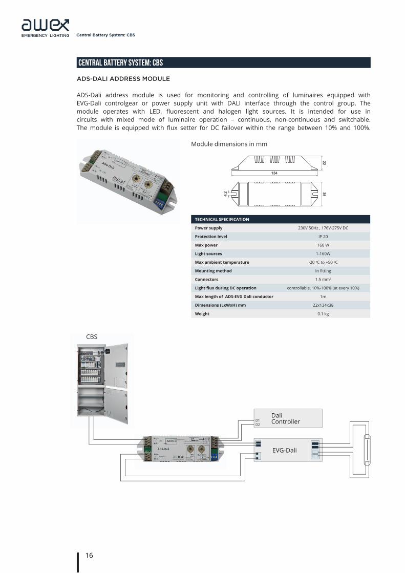
aDs-Dali aDDress moDule
ADS-Dali address module is used for monitoring and controlling of luminaires equipped with EVG-Dali controlgear or power supply unit with DALI interface through the control group. The module operates with LED, fl uorescent and halogen light sources. It is intended for use in circuits with mixed mode of luminaire operation – continuous, non-continuous and switchable.The module is equipped with fl ux setter for DC failover within the range between 10% and 100%.
TECHNICAL SPECIFICATION
Power supply 230V 50Hz , 176V-275V DC
Protection level IP 20
Max power 160 W
Light sources 1-160W
Max ambient temperature -20 oC to +50 oC
Mounting method In fi tting
Connectors 1.5 mm2
Light fl ux during DC operation controllable, 10%-100% (at every 10%)
Max length of ADS-EVG Dali conductor 1m
Dimensions (LxWxH) mm 22x134x38
Weight 0.1 kg
Module dimensions in mm
DaliController
EVG-Dali
D1D2
134
22
38
4,2
18
,5
425
18
,5
157
157
4 418
7
21
15
CBS

17
Central Battery System: CBS
CENTRAL BATTERY SYSTEM: CBS
mP 500 sWitching moDule
The MP 500 module is used for switching on the mains power operation of a luminaire or group of luminaires using the basic lighting switch. The application of this module allows the use of basic lighting luminaires as the emergency lighting luminaires.
TECHNICAL SPECIFICATION
Power supply 230V 50Hz, 220V DC ± 20%
Protection level IP 20
Max power 500 VA
Connecting clips 3x2.5mm2
Max ambient temperature -10 oC to +40 oC
Mounting method In fitting
Weight 0.1 kg
Module dimensions in mm
134
22
38
4,2
18
,5
425
18
,5
157
157
4 418
7
21
15
CBML
TO
LN
MP 500N(-)L(+)NL
N(-)L(+)
OFF
ON
CB - central battery
ML - linear module input
CZF - phase loss sensor
TO - basic lighting switch board
LS-24 - potential free input module
MP 500 - switching module
- emergency ligthing fitting
- basic lighting fitting
PHASE CANCELLATION
POWER SUPPLY
TO CB
NO ON ~230V 0V ON ON
NO OFF ~230V 0V OFF OFF
YES ON ~0V -230V ON OFF
YES OFF ~0V -230V ON OFF
ON
OFF
LS-24
CZF
18
Central Battery System: CBS
CENTRAL BATTERY SYSTEM: CBS
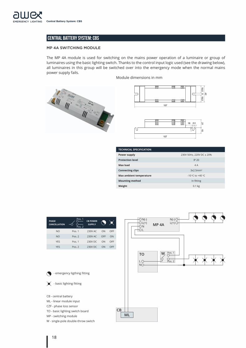
mP 4a sWitching moDule
The MP 4A module is used for switching on the mains power operation of a luminaire or group of luminaires using the basic lighting switch. Thanks to the control input logic used (see the drawing below), all luminaires in this group will be switched over into the emergency mode when the normal mains power supply fails.
TECHNICAL SPECIFICATION
Power supply 230V 50Hz, 220V DC ± 20%
Protection level IP 20
Max load 4 A
Connecting clips 3x2.5mm2
Max ambient temperature -10 oC to +40 oC
Mounting method In fitting
Weight 0.1 kg
Module dimensions in mm
134
22
38
4,2
18
,5
425
18
,5
157
157
4 418
7
21
15
CBML
TO
LN
MP 4AN(-)L(+)NL
N(-)L(+)
W Pos. 1
Pos. 2
CB - central battery
ML - linear module input
CZF - phase loss sensor
TO - basic lighting switch board
MP - switching module
W - single-pole double-throw switch
- emergency ligthing fitting
- basic lighting fitting
PHASE CANCELLATION
CB POWER SUPPLY
NO Pos. 1 230V AC ON OFF
NO Pos. 2 230V AC OFF ON
YES Pos. 1 230V DC ON OFF
YES Pos. 2 230V DC ON OFF
Pos. 1
Pos. 2
19
Central Battery System: CBS
CENTRAL BATTERY SYSTEM: CBS
sD memory carD
The SD memory card allows saving event log records and their readout and printout from PC using standard word processors. In addition, the card allows saving the system confi guration and upgrading the fi rmware.
TECHNICAL SPECIFICATION
Power supply 230V 50Hz, 176V-275V DC
Connection thresholds In compliance with the PN-EN 60598-2-22 standard
Mounting method On DIN rail
Dead time < 200ms
Connectors 2.5 mm2
Contact 230V/50Hz 0.5A NO
Saved data:• Text system description• Description of each circuit• Description of each luminaire• Description of each control• Description of each control group• Full system confi guration• Event log• Firmware
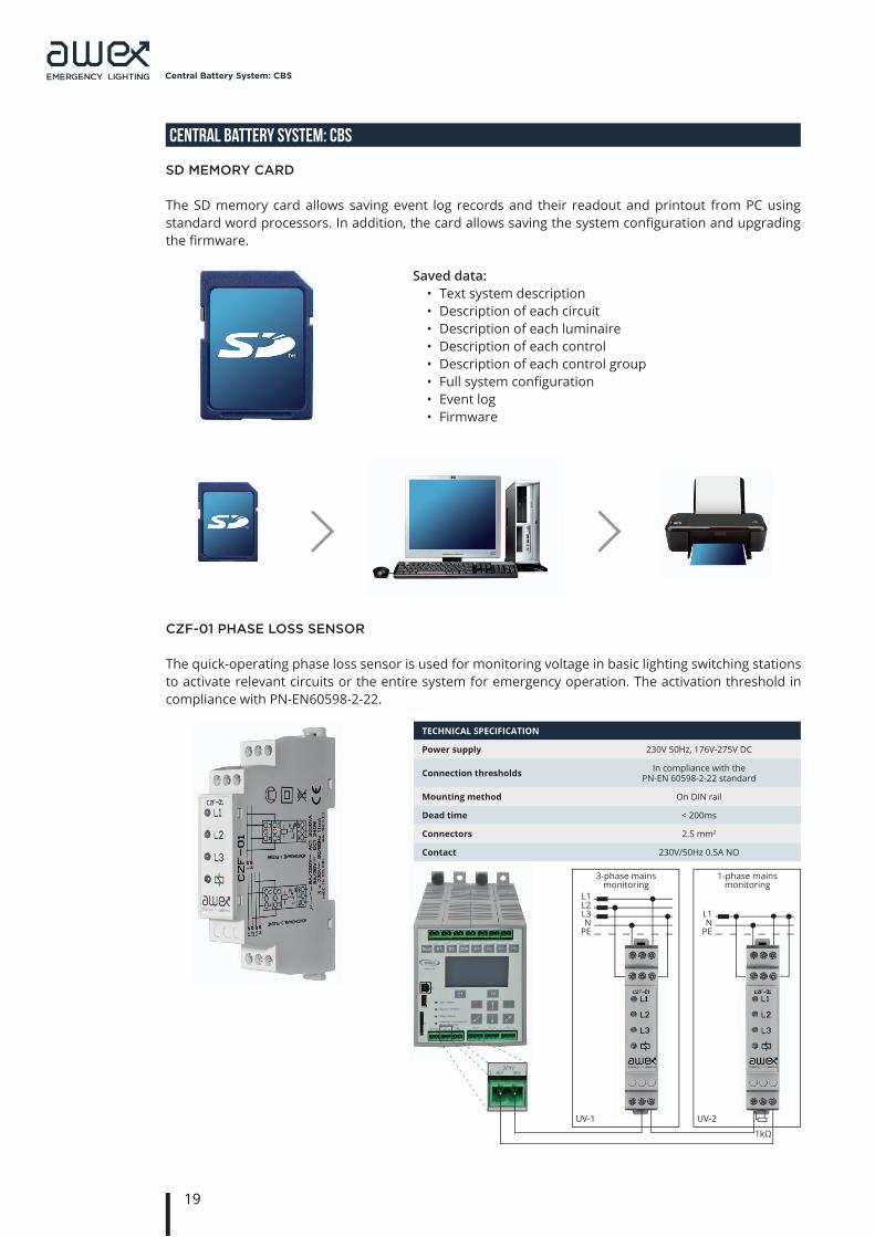
cZf-01 Phase loss sensor
The quick-operating phase loss sensor is used for monitoring voltage in basic lighting switching stations to activate relevant circuits or the entire system for emergency operation. The activation threshold in compliance with PN-EN60598-2-22.
L1L2L3N
PE
L1N
PE
UV-1 UV-2
3-phase mains monitoring
1-phase mains monitoring
1kΩ
20
Central Battery System: CBS
CENTRAL BATTERY SYSTEM: CBS
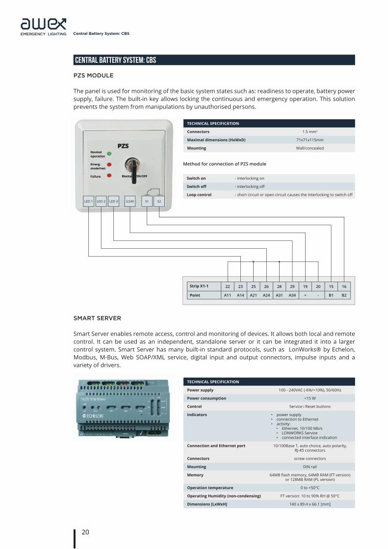
PZs moDule
The panel is used for monitoring of the basic system states such as: readiness to operate, battery power supply, failure. The built-in key allows locking the continuous and emergency operation. This solution prevents the system from manipulations by unauthorised persons.
TECHNICAL SPECIFICATION
Connectors 1.5 mm2
Maximal dimensions (HxWxD) 71x71x115mm
Mounting Wall/concealed
Method for connection of PZS module
Switch on - interlocking on
Switch off - interlocking off
Loop control - short circuit or open circuit causes the interlocking to switch off LED 1 LED 2 LED 3 U24V S1 S2
Strip X1-1 22 23 25 26 28 29 19 20 15 16
Point A11 A14 A21 A24 A31 A34 + - B1 B2
smart server
Smart Server enables remote access, control and monitoring of devices. It allows both local and remote control. It can be used as an independent, standalone server or it can be integrated it into a larger control system. Smart Server has many built-in standard protocols, such as LonWorks® by Echelon, Modbus, M-Bus, Web SOAP/XML service, digital input and output connectors, impulse inputs and a variety of drivers.
TECHNICAL SPECIFICATION
Power supply 100 - 240VAC (-6%/+10%), 50/60Hz
Power consumption <15 W
Control Service i Reset buttons
Indicators • power supply • connection to Ethernet• activity:
• Ethernet, 10/100 Mb/s• LONWORKS Service• connected interface indication
Connection and Ethernet port 10/100Base T, auto choice, auto polarity, RJ-45 connectors
Connectors screw connectors
Mounting DIN rail
Memory 64MB fl ash memory, 64MB RAM (FT version) or 128MB RAM (PL version)
Operation temperature 0 to +50°C
Operating Humidity (non-condensing) FT version: 10 to 90% RH @ 50°C
Dimensions [LxWxH] 140 x 89.4 x 66.1 [mm]

Group 1The GRUP can consist of maximum 10 systems. SYSTEM 1 serves as MASTER.
The remaining elements are equipped with M-SL
controllers.
Total length of the LON1 bus in linear topology is max
900m (JY(ST)Y 2x2x0.8mm2).
The system can be expanded with PBS.../H substations. Maximum10 HUB modules.
21
Central Battery System: CBS
CENTRAL BATTERY SYSTEM: CBS
system structure
Communication with ELS 230V external modules, substations with controller as well as substations with HUB module (remote cabinets) is based on LonTalk communication protocol. 3 LonTalk interfaces are implemented in the controller. The first one, LON1, is intended for communication between systems with controller and supervision systems of BMS type. LON2 interface is intended for communication with external sensor modules of ELS 230 type. Whereas LON3 is reserved for substations equipped with HUB module.
Communication diagram of the central battery system.
Maximum 4 system groups
GROUP 1 GROUP 2 GROUP 3 GROUP4
SYSTEM WITH NO ADDRESS
max 900mm
ax. 5
00m
GRUP topology
SYSTEM topology
LON Bus 1 (BMS)
LON Bus 1 (BMS)
LON Bus 2
LON Bus 3
SYSTEM 1 (Master Controller ) (Group 1, System 1)
M-SL + L980
SYSTEM N (Group 1, System N)
SYSTEM 10 (Group 1, System 10)
CONTROLLER
• L-980+ BST-980• Battery set• ML, ML-S• LS-24, LS-230• Printer• PYXOS cabinet internal communication
ELS-230no. 1
HUB 1(Subsystem 1)
HUB 10(Subsystem 10)
ELS-230no. N
ML 1 orLS-24, LS-230
no. 1
ML 1 orLS-24, LS-230
no. 1
ELS-230no. 30
ML 5 orLS-24, LS-230
no. 5
ML 5 or LS-24, LS-230
no. 5
PBS/.../H substation
22
Central Battery System: CBS
CENTRAL BATTERY SYSTEM: CBS
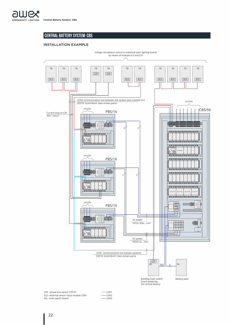
installation eXamPle
Z
AS
ILA
CZ
D
C
Z
AS
ILA
CZ
A
C
S
UM
AT
OR
Z
AS
ILA
CZ
D
C
Z
AS
ILA
CZ
A
C
S
UM
AT
OR
AC power
DC power
ELS
TB
ELS
TB
ELS
TB
ELS
TB
ELS
TB
ELS
TB
ELS
TB
ELS
TB
ELS
TB
CZF
TB
CZF
TB
Voltage cancellation control in individual basic lighting boards
by means of modules ELS and CZF
RG
Building main switch board powering the central battery
Battery pack
LONI- communication line betwen systems
LON2-communication line between the system and modules ELS
CZF
PA
Current loop to CZF PBS/16
PBS/16
circuits
PBS/16
circuits
CBS/56
circuits
circuits
YKY¿o 3(5)x....mm2
NHXH 3x....mm2
3 3
3 3
2JY(ST)Y 2x2x0.8mm (two screen pairs)
2JY(ST)Y 2x2x0.8mm (two screen pairs)
2YDY 1.5mm
BOOSTER BOOSTER BOOSTER BOOSTER
CHARGER
33(5)
CZF - phase loss sensor CZF-01
ELS - external sensor input module 230V
RG - main switch board
LON1
LON2
LON3
Z
AS
ILA
CZ
D
C
ZA
SIL
AC
Z
DC
S
UM
AT
OR
D
C P
OW
ER
SO
UR
CE
A
C P
OW
ER
SO
UR
CE
A
DD
ER
LS-24
D
C P
OW
ER
SO
UR
CE
A
C P
OW
ER
SO
UR
CE
A
DD
ER
D
C P
OW
ER
SO
UR
CE
A
C P
OW
ER
SO
UR
CE
A
DD
ER
D
C P
OW
ER
SO
UR
CE
A
DD
ER
D
C P
OW
ER
SO
UR
CE
23
Central Battery System: CBS
CENTRAL BATTERY SYSTEM: CBS
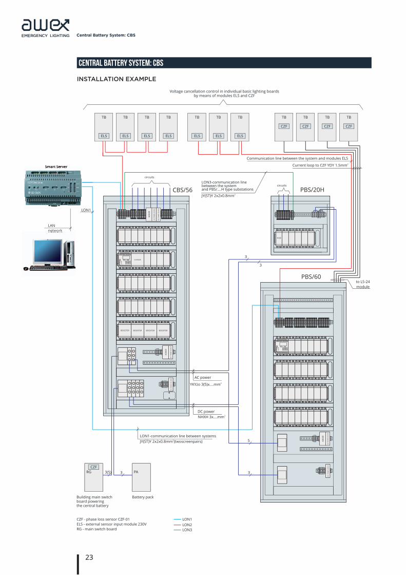
installation eXamPle
AC power
DC power
ELS
TB
ELS
TB
ELS
TB
ELS
TB
ELS
TB
ELS
TB
ELS
TB TB TB
CZF
TB
CZF
TB
Voltage cancellation control in individual basic lighting boards by means of modules ELS and CZF
circuits
Building main switch board powering the central battery
Communication line between the system and modules ELS
3
3
2Current loop to CZF YDY 1.5mm
CZF CZF
3
5
PBS/20H
circuits
CBS/56
PBS/60
LON3-communication line between the system and PBS/....H type substations
JY(ST)Y 2x2x0.8 mm 2
YKY¿o 3(5)x....mm2
NHXH 3x....mm2
Smart Server
LAN
network
RG
Battery pack
CZF
PA
CZF - phase loss sensor CZF-01
ELS - external sensor input module 230V
RG - main switch board
LON1-communication line between systems
JY(ST)Y 2x2x0.8 mm 2(two screen pairs)
LON 1
CHARGER
HUB
33(5)
to LS-24
module
LON1
LON2
LON3
Z
AS
ILA
CZ
D
C
S
UM
AT
OR
Z
AS
ILA
CZ
D
C
Z
AS
ILA
CZ
D
C
S
UM
AT
OR
BOOSTER BOOSTER BOOSTER BOOSTER
Z
AS
ILA
CZ
D
C
D
C P
OW
ER
SO
UR
CE
A
C P
OW
ER
SO
UR
CE
A
DD
ER
D
C P
OW
ER
SO
UR
CE
A
DD
ER
D
C P
OW
ER
SO
UR
CE
D
C P
OW
ER
SO
UR
CE
A
DD
ER
D
C P
OW
ER
SO
UR
CE
Smart Server
network
24
Central Battery System: CBS
CENTRAL BATTERY SYSTEM: CBS
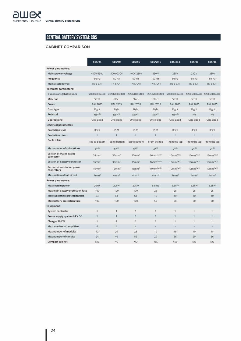
CBS/24 CBS/40 CBS/56 CBS/20-C CBS/36-C CBS/20 CBS/36
Power parameters:
Mains power voltage 400V/230V 400V/230V 400V/230V 230 V 230V 230 V 230V
Frequency 50 Hz 50 Hz 50 Hz 50 Hz 50 Hz 50 Hz 50 Hz
Mains system type TN-S-C/IT TN-S-C/IT TN-S-C/IT TN-S-C/IT TN-S-C/IT TN-S-C/IT TN-S-C/IT
Technical parameters:
Dimensions (HxWxD)mm 2050x800x400 2050x800x400 2050x800x400 2050x800x400 2050x800x400 1200x800x400 1200x800x400
Material Steel Steel Steel Steel Steel Steel Steel
Colour RAL 7035 RAL 7035 RAL 7035 RAL 7035 RAL 7035 RAL 7035 RAL 7035
Door type Right Right Right Right Right Right Right
Pedestal No*(1) No*(1) No*(1) No*(1) No*(1) No No
Door locking One sided One sided One sided One sided One sided One sided One sided
Electrical parameters:
Protection level IP 21 IP 21 IP 21 IP 21 IP 21 IP 21 IP 21
Protection class I I I I I I I
Cable inlets Top to bottom Top to bottom Top to bottom From the top From the top From the top From the top
Max number of substations 6*(3) 6*(3) 6*(3) 2*(3) 2*(3) 2*(3) 2*(3)
Section of mains power connector 35mm2 35mm2 35mm2 16mm2*(2) 16mm2*(2) 16mm2*(2) 16mm2*(2)
Section of battery connector 35mm2 35mm2 35mm2 16mm2*(2) 16mm2*(2) 16mm2*(2) 16mm2*(2)
Section of substation power connectors 16mm2 16mm2 16mm2 10mm2*(2) 10mm2*(2) 10mm2*(2) 10mm2*(2)
Max section of tail circuit 4mm2 4mm2 4mm2 4mm2 4mm2 4mm2 4mm2
Power parameters:
Max system power 20kW 20kW 20kW 5.5kW 5.5kW 5.5kW 5.5kW
Max main battery protection fuse 100 100 100 25 25 25 25
Max substation protection fuse 63 63 63 10 10 10 10
Max battery protection fuse 100 100 100 50 50 50 50
Equipment:
System controller 1 1 1 1 1 1 1
Power supply system 24 V DC 1 1 1 1 1 1 1
Charger 980 W 1 1 1 1 1 1 1
Max number of amplifiers 4 4 4 - - - -
Max number of modules 12 20 28 10 18 10 18
Max number of circuits 24 40 56 20 36 20 36
Compact cabinet NO NO NO YES YES NO NO
caBinet comParison
25
Central Battery System: CBS
CENTRAL BATTERY SYSTEM: CBS
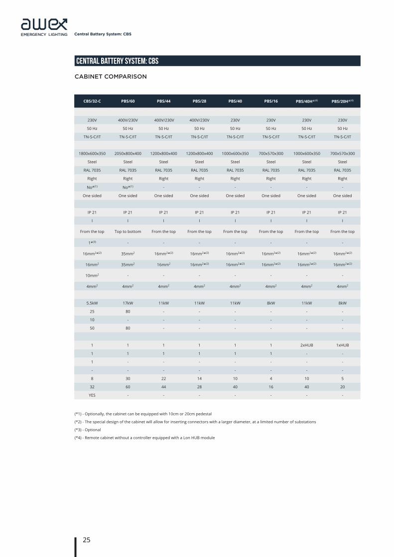
(*1) - Optionally, the cabinet can be equipped with 10cm or 20cm pedestal
(*2) - The special design of the cabinet will allow for inserting connectors with a larger diameter, at a limited number of substations
(*3) - Optional
(*4) - Remote cabinet without a controller equipped with a Lon HUB module
CBS/32-C PBS/60 PBS/44 PBS/28 PBS/40 PBS/16 PBS/40H*(4) PBS/20H*(4)
230V 400V/230V 400V/230V 400V/230V 230V 230V 230V 230V
50 Hz 50 Hz 50 Hz 50 Hz 50 Hz 50 Hz 50 Hz 50 Hz
TN-S-C/IT TN-S-C/IT TN-S-C/IT TN-S-C/IT TN-S-C/IT TN-S-C/IT TN-S-C/IT TN-S-C/IT
1800x600x350 2050x800x400 1200x800x400 1200x800x400 1000x600x350 700x570x300 1000x600x350 700x570x300
Steel Steel Steel Steel Steel Steel Steel Steel
RAL 7035 RAL 7035 RAL 7035 RAL 7035 RAL 7035 RAL 7035 RAL 7035 RAL 7035
Right Right Right Right Right Right Right Right
No*(1) No*(1) - - - - - -
One sided One sided One sided One sided One sided One sided One sided One sided
IP 21 IP 21 IP 21 IP 21 IP 21 IP 21 IP 21 IP 21
I I I I I I I I
From the top Top to bottom From the top From the top From the top From the top From the top From the top
1*(3) - - - - - - -
16mm2*(2) 35mm2 16mm2*(2) 16mm2*(2) 16mm2*(2) 16mm2*(2) 16mm2*(2) 16mm2*(2)
16mm2 35mm2 16mm2 16mm2*(2) 16mm2*(2) 16mm2*(2) 16mm2*(2) 16mm2*(2)
10mm2 - - - - - - -
4mm2 4mm2 4mm2 4mm2 4mm2 4mm2 4mm2 4mm2
5.5kW 17kW 11kW 11kW 11kW 8kW 11kW 8kW
25 80 - - - - - -
10 - - - - - - -
50 80 - - - - - -
1 1 1 1 1 1 2xHUB 1xHUB
1 1 1 1 1 1 - -
1 - - - - - - -
- - - - - - - -
8 30 22 14 10 4 10 5
32 60 44 28 40 16 40 20
YES - - - - - - -
caBinet comParison
26
Central Battery System: CBS
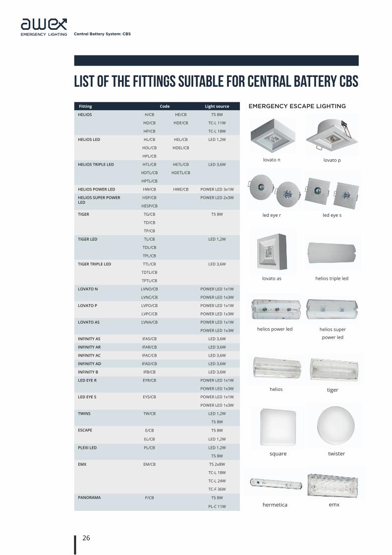
List of the Fittings Suitable for Central Battery CBS Fitting Code Light source
HELIOS H/CB HE/CB T5 8W
HD/CB HDE/CB TC-L 11W
HP/CB TC-L 18W
HELIOS LED HL/CB HEL/CB LED 1,2W
HDL/CB HDEL/CB
HPL/CB
HELIOS TRIPLE LED HTL/CB HETL/CB LED 3,6W
HDTL/CB HDETL/CB
HPTL/CB
HELIOS POWER LED HW/CB HWE/CB POWER LED 3x1W
HELIOS SUPER POWER LED
HSP/CB POWER LED 2x3W
HESP/CB
TIGER TG/CB T5 8W
TD/CB
TP/CB
TIGER LED TL/CB LED 1,2W
TDL/CB
TPL/CB
TIGER TRIPLE LED TTL/CB LED 3,6W
TDTL/CB
TPTL/CB
LOVATO N LVNO/CB POWER LED 1x1W
LVNC/CB POWER LED 1x3W
LOVATO P LVPO/CB POWER LED 1x1W
LVPC/CB POWER LED 1x3W
LOVATO AS LVNA/CB POWER LED 1x1W
POWER LED 1x3W
INFINITY AS IFAS/CB LED 3,6W
INFINITY AR IFAR/CB LED 3,6W
INFINITY AC IFAC/CB LED 3,6W
INFINITY AD IFAD/CB LED 3,6W
INFINITY B IFB/CB LED 3,6W
LED EYE R EYR/CB POWER LED 1x1W
POWER LED 1x3W
LED EYE S EYS/CB POWER LED 1x1W
POWER LED 1x3W
TWINS TW/CB LED 1,2W
T5 8W
ESCAPE E/CB T5 8W
EL/CB LED 1,2W
PLEXI LED PL/CB LED 1,2W
T5 8W
EMX EM/CB T5 2x8W
TC-L 18W
TC-L 24W
TC-F 36W
PANORAMA P/CB T5 8W
PL-C 11W
lovato n
led eye r
helios power led
helios
square
hermetica
lovato p
led eye s
helios super
power led
tiger
twister
emx
lovato as helios triple led
emergency escaPe lighting
27
Central Battery System: CBS
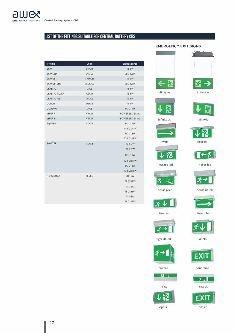
List of the Fittings Suitable for Central Battery CBS
Fitting Code Light source
SKW SK/CB T5 8W
SKW LED SKL/CB LED 1,2W
SKW DS SKD/CB T5 8W
SKW DS LED SKDL/CB LED 1,2W
CLASSIC C/CB T5 8W
CLASSIC SILVER CS/CB T5 8W
CLASSIC FW CW/CB T5 8W
DUBLO DS/CB T5 8W
QUADRO Q/CB TC-L 11W
VIPER R VR/CB POWER LED 3x1W
VIPER S VS/CB POWER LED 3x1W
SQUARE SD/CB TC-L 11W
TC-L 2x11W
TC-L 18W
TC-L 2x18W
TWISTER TD/CB TC-L 7W
TC-L 9W
TC-L 11W
TC-L 2x11W
TC-L 18W
TC-L 2x18W
HERMETICA HR/CB T8 18W
T8 2X18W
T8 36W
T8 2x36W
T8 58W
T8 2x58W
infinity as
infinity ac
twins plexi led
escape led
helios p led
tiger led
tiger ds led
quadro panorama
dublo
tiger p led
helios ds led
helios led
infinity b
infinity ar
skw skw ds
classicviper r
emergency eXit signs
28
System Centralnej Baterii: CBS
normy i przepisy
scoPe of aPPlication
The emergency lighting installations should be designed in any civil structures where the mains voltage loss may result in a danger to the life or health of people, serious environmental risk as well as significant material loss (Regulation of the Minister of Infrastructure of 12 April 2002 – the Official Journal of Laws no. 75 item 690 as amended, Regulation of the Minister of Infrastructure of 12 March 2009 – the Official Journal of Laws no. 56 item 461 as amended and Regulation of the Minister of Infrastructure of 10 December 2010 – the Official Journal of Laws no. 239 item 1597).
By virtue of law, the evacuation lighting should be used in:
1. Rooms:• cinemas, theatres and concert halls as well as other entertainment venues,• auditoria, conference rooms, entertainment establishments and sports halls for more than 200
people,• exhibition halls in museums,• with area of more than 1 000 m² in garages illuminated with light only.
2. Escape routes:• from rooms mentioned in item 1,• illuminated with artificial light only,• in hospitals and other buildings mainly intended for people with limited movement ability to stay in,• in tall and high-rise public utility buildings and boarding houses.
3. In temporary buildings if intended for show purposes or other gatherings.
4. In rooms with pneumatic housing if to be used as temporary manufacturing and storage buildings with fire load within the fire zone of up to 1000 MJ/m².
5. In temporary tent-like buildings intended for show purposes.
6. In dispatch rooms, technical rooms of gas compressor station (and within the premises of gas compressor station).
STANDARDS AND REGULATIONS
29
Central Battery System: CBS
STANDARDS AND REGULATIONS
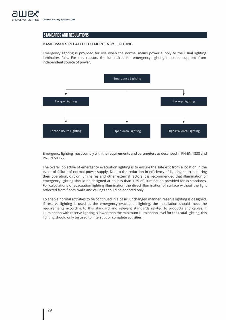
Emergency lighting is provided for use when the normal mains power supply to the usual lighting luminaires fails. For this reason, the luminaires for emergency lighting must be supplied from independent source of power.
Basic issues relateD to emergency lighting
Emergency lighting must comply with the requirements and parameters as described in PN-EN 1838 and PN-EN 50 172.
The overall objective of emergency evacuation lighting is to ensure the safe exit from a location in the event of failure of normal power supply. Due to the reduction in efficiency of lighting sources during their operation, dirt on luminaires and other external factors it is recommended that illumination of emergency lighting should be designed at no less than 1.25 of illumination provided for in standards. For calculations of evacuation lighting illumination the direct illumination of surface without the light reflected from floors, walls and ceilings should be adopted only.
To enable normal activities to be continued in a basic, unchanged manner, reserve lighting is designed. If reserve lighting is used as the emergency evacuation lighting, the installation should meet the requirements according to this standard and relevant standards related to products and cables. If illumination with reserve lighting is lower than the minimum illumination level for the usual lighting, this lighting should only be used to interrupt or complete activities.
Emergency Lighting
Escape Lighting Backup Lighting
High-risk Area LightingOpen Area LightingEscape Route Lighting
30
Central Battery System: CBS
STANDARDS AND REGULATIONS
escaPe route lighting
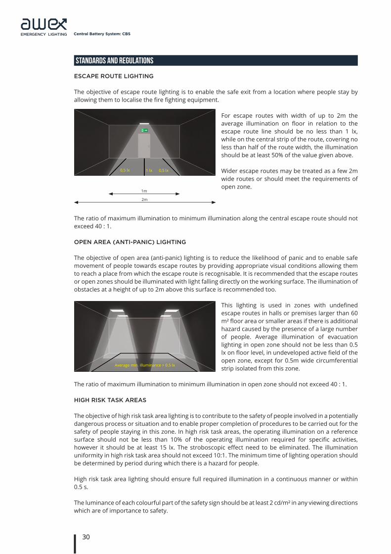
The objective of escape route lighting is to enable the safe exit from a location where people stay by allowing them to localise the fire fighting equipment.
For escape routes with width of up to 2m the average illumination on floor in relation to the escape route line should be no less than 1 lx, while on the central strip of the route, covering no less than half of the route width, the illumination should be at least 50% of the value given above.
Wider escape routes may be treated as a few 2m wide routes or should meet the requirements of open zone.
The ratio of maximum illumination to minimum illumination along the central escape route should not exceed 40 : 1.
oPen area (anti-Panic) lighting
The objective of open area (anti-panic) lighting is to reduce the likelihood of panic and to enable safe movement of people towards escape routes by providing appropriate visual conditions allowing them to reach a place from which the escape route is recognisable. It is recommended that the escape routes or open zones should be illuminated with light falling directly on the working surface. The illumination of obstacles at a height of up to 2m above this surface is recommended too.
This lighting is used in zones with undefined escape routes in halls or premises larger than 60 m² floor area or smaller areas if there is additional hazard caused by the presence of a large number of people. Average illumination of evacuation lighting in open zone should not be less than 0.5 lx on floor level, in undeveloped active field of the open zone, except for 0.5m wide circumferential strip isolated from this zone.
The ratio of maximum illumination to minimum illumination in open zone should not exceed 40 : 1.
high risk task areas
The objective of high risk task area lighting is to contribute to the safety of people involved in a potentially dangerous process or situation and to enable proper completion of procedures to be carried out for the safety of people staying in this zone. In high risk task areas, the operating illumination on a reference surface should not be less than 10% of the operating illumination required for specific activities, however it should be at least 15 lx. The stroboscopic effect need to be eliminated. The illumination uniformity in high risk task area should not exceed 10:1. The minimum time of lighting operation should be determined by period during which there is a hazard for people.
High risk task area lighting should ensure full required illumination in a continuous manner or within 0.5 s.
The luminance of each colourful part of the safety sign should be at least 2 cd/m² in any viewing directions which are of importance to safety.
31
Central Battery System: CBS
STANDARDS AND REGULATIONS
arrangement of luminaires for evacuation lighting
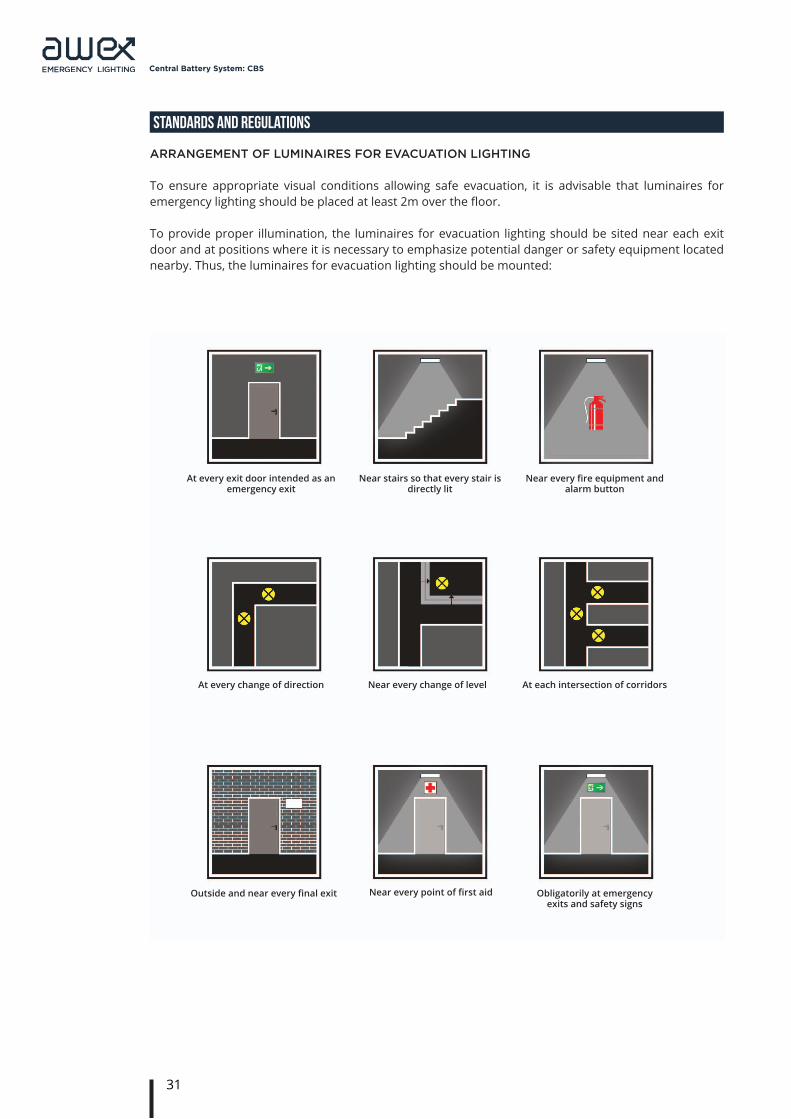
To ensure appropriate visual conditions allowing safe evacuation, it is advisable that luminaires for emergency lighting should be placed at least 2m over the floor.
To provide proper illumination, the luminaires for evacuation lighting should be sited near each exit door and at positions where it is necessary to emphasize potential danger or safety equipment located nearby. Thus, the luminaires for evacuation lighting should be mounted:
Near stairs so that every stair is directly lit
Near every change of level
Near every point of first aid
At every exit door intended as an emergency exit
At every change of direction
Outside and near every final exit
At each intersection of corridors
Obligatorily at emergency exits and safety signs
Near every fire equipment and alarm button
32
Central Battery System: CBS
STANDARDS AND REGULATIONS
If first aid posts or fire fighting equipment and fire alarm push-buttons are not on the escape route or in an open area, they should be illuminated so that the illumination at floor level is at least 5 lx.
Emergency lighting should also be designed in other dangerous zones as well as areas that should be accessible in the event of the usual lighting installation failure. Such areas include:
• lift cars (to prevent a panic);• moving stairways and walkways;• toilet facilities, lobbies, dressing rooms and cloakrooms larger than 8 m² and rooms for use by the
disabled;• technical rooms where evacuation lighting should meet the requirements of open zone lighting
or, if required, the assumptions as for special hazard area;• covered car parks;• hospitals – the evacuation lighting at intensive care departments and in operating rooms should
not be less than the required usual illumination (if there is no reserve lighting).
safety signs
Signs at any emergency exits along the escape routes should be illuminated so that they indicate unambiguously the route of escape to a point of safety. [PN EN 1838:2005].
An exit or directional sign should always be visible from all points along the escape route. Any signs indicating the emergency exits and escape routes should have identical colour and format, while their luminance should be at least 2cd/m².
As people staying in building may not know it well, the use of safety marks illuminated internally and supplied on a continuous basis is recommended.
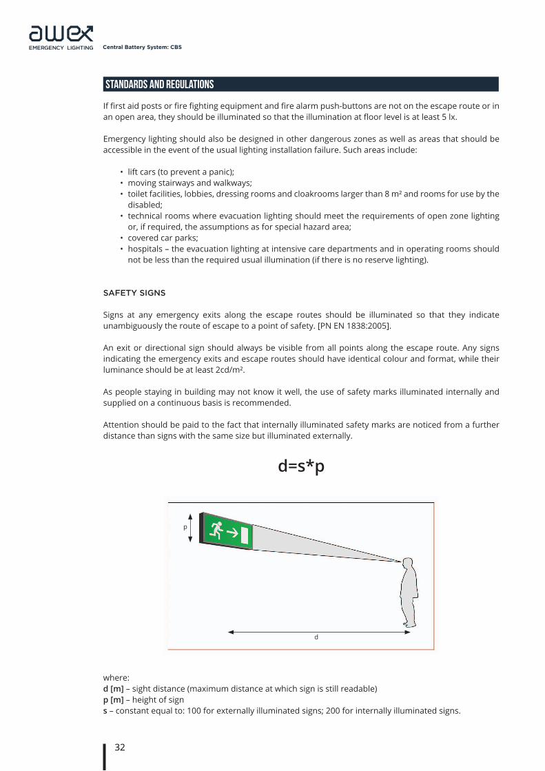
Attention should be paid to the fact that internally illuminated safety marks are noticed from a further distance than signs with the same size but illuminated externally.
d=s*p
where:d [m] – sight distance (maximum distance at which sign is still readable)p [m] – height of signs – constant equal to: 100 for externally illuminated signs; 200 for internally illuminated signs.
p
d
33
Central Battery System: CBS
STANDARDS AND REGULATIONS
1. emergency lighting installations anD systems
Power supply to emergency evacuation lighting should be provided promptly, automatically and for a suitable time in a specified area when the normal mains power supply to the usual lighting installation fails.
The emergency evacuation lighting installation should provide the following features:
• illuminate the escape route signs,• produce illumination on escape routes so that movement towards the evacuation exit of a location
is safe;• ensure that fire alarm push-buttons and fire fighting equipment distributed along the escape routes
can be localised and used easily,• allow conducting activities related to safety measures.
The emergency evacuation lighting should be activated not only in the event when the normal mains power supply to the usual lighting installation fails completely, but also in case of local damage such as the final circuit damage. At the stage of designing the emergency lighting installation, all cases should be taken into consideration to be sure that emergency lighting will operate in the event when the normal mains power supply fails in a specific zone.
The emergency lighting installation includes all the equipment and components within a specific facility which are interconnected to execute tasks set to emergency lighting. In particular, this concerns the duration of operation, provision of proper illumination, use of basic or night lighting, reporting events as well as safe operation and activities of rescue teams also in case of fire.
The following are components of an emergency lighting installation:
• emergency lighting systems with central or individual power supply source (batteries);• luminaires for emergency lighting designed for central or individual power supply source (batteries)
along with equipment (ignition systems, switching and address modules for systems with central power supply source or inverters, address modules and batteries for systems with individual power supply source);
• conductors and cables used to connect the emergency lighting system with luminaires;• trays, culverts, slings and mechanical systems for mounting cables used for connections in
emergency lighting installations;• equipment designed additionally for emergency lighting systems, e.g. remote control, modules for
connection to central computer, luminaire supply circuit supervision systems, systems that allow the operation with fire fighting equipment and others used in emergency lighting installations.
2. event log anD testing of emergency lighting systems
Shop drawings of completed emergency evacuation lighting installation should be delivered and kept in the premises of the property. The drawings should include all the luminaires and basic components. These data should be updated according to successive alterations made in the system. The drawings should be signed by a competent person in charge of verification of the design with regard to the requirements in this standard. In addition, the log should be kept to record routine reports, tests, damages and changes.
These records should be available either as handwritten records or printouts from the automatic testing devices.
The log should be kept within the premises of the property under supervision of relevant person appointed by the occupier/owner; it should be easily available for inspection by any authorised person.The log should be used for recording the following information:
34
Central Battery System: CBS
STANDARDS AND REGULATIONS
• date of ordering the system, along with certificate that specifies any changes;• date of every periodic inspection and test;• date and concise description of every service and inspection or completed tests;• date and concise description of every damage and repairs made;• date and concise description of any change in the emergency lighting installation;• when automatic testing devices are used, their basic characteristics and mode of operation should
be described.
Regular servicing is essential. The occupier/owner of the property should appoint a competent person to supervise servicing of the system. This person should be given sufficient authority to ensure the carrying out of any work necessary to maintain the system in correct operational mode.
When automatic testing devices are used, the information should be recorded monthly. For any other systems tests should be performed according to the requirements of PN-EN 50172 and their results should be entered in the log.
Tests and inspections of emergency lighting equipment
Because of the possibility of a failure of the normal lighting supply occurring shortly after a period of testing of the emergency lighting system or during the subsequent recharge period, all full duration tests shall, wherever possible, be undertaken just before a time of low risk to allow for battery recharge. It will allow safe battery recharging. Alternatively, suitable temporary arrangements shall be made until the batteries have been recharged.
Daily inspection
The objective of visual inspection is to identify that the central power supply system is operational and whether no test is required for the system. The inspection is based on visual inspection of system indicators.
Monthly test
When automatic testing devices are used, the results of short-time tests should be recorded. In case of other systems the monthly test is based on inspection of the emergency lighting system with regard to its functionalities, i.e. by simulation of a failure of the normal mains power supply. It needs to be checked whether all the envisaged luminaires for evacuation lighting and safety signs have switched to the emergency operation mode and returned to normal operation after the mains power supply has been restored.The test duration should be sufficient to check the functioning of luminaires in tested zone. During this period, all the lighting luminaires and signs should be checked to ensure that they are present, clean and functioning properly.
Yearly test
When automatic testing devices are used, the results of full rated duration of the emergency lights should be recorded. In case of any other systems the yearly test is based on inspection of the emergency lighting system with regard to its functionalities, i.e. by simulation of a failure to the normal mains power supply. It needs to be checked whether all the envisaged luminaires for evacuation lighting and safety signs have switched to the emergency operation mode and returned to normal operation after the mains power supply has been restored.
The test duration should be sufficient to check the envisaged backup autonomy in accordance with the manufacturer’s information. During the test every warning lamp or device should be checked to ensure that their indications are correct.
The charging system is recommended to be checked for correct operation.
35
Central Battery System: CBS
STANDARDS AND REGULATIONS
3. emergency evacuation lighting eQuiPment
The emergency luminaires for evacuation lighting should be designed and made in accordance with PN-EN 60598-2-22:2004/AC Luminaires – Part 2-22: Particular Requirements. Luminaires for emergency lighting should be selected in accordance to their location. Luminaires used in ex-zones should comply with relevant standards and directive 94/9/EC.
The evacuation lighting luminaire igniters should comply with PN-EN 61347:2005 (multi-part standard) Lamp controlgear - Part 2-7: Particular requirements for battery supplied electronic controlgear for emergency lighting. Due to the amount of power output, an important parameter of igniters is the volume of impulse striking current and its duration. These parameters should be selected so that they do not result in a damage to contact parts of elements in power supply circuits (e.g. fuse bases, relay contacts etc). The central power supply systems of emergency lighting should be designed and made in compliance with PN-EN 50171:2007: Central power supply systems. The safety requirements for batteries should be in compliance with PN-EN 50272-2:2007: Safety requirements for secondary batteries and battery installations - Part 2: Stationary batteries.
Due to different operation modes inside safety devices, the description of types of central emergency power supply systems is necessary.
To ensure safety of rescue teams, during their operation in emergency mode the power supply systems should work in IT system with devices for constant control of insulation.
The automatic emergency lighting test systems should be designed, made and installed in compliance with relevant requirements of domestic standards and regulations.
4. classification of luminaires anD Protection classes
Classification of luminaires
The resistance of electric devices and equipment to adverse environmental impact as well as protection against touching live parts by the operator depends on how the external guards and casing of the device is made.
The above-mentioned resistance is referred to as the ingress protection and marked using the so-called IP classification.
According to this classification, electric devices are marked with two-digit code preceded by IP symbol.(PN-EN 60529:2003).
36
Central Battery System: CBS
STANDARDS AND REGULATIONS
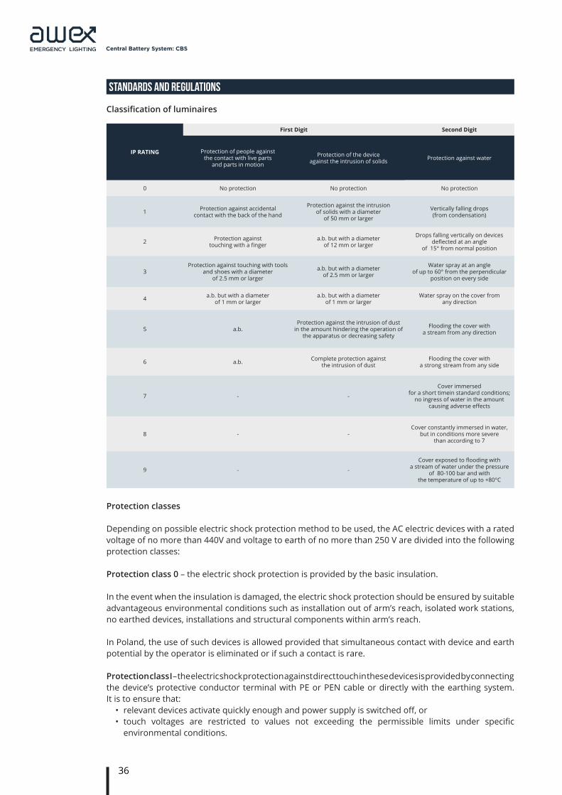
Classification of luminaires
IP RATING
First Digit Second Digit
Protection of people against the contact with live parts
and parts in motion
Protection of the device against the intrusion of solids Protection against water
0 No protection No protection No protection
1 Protection against accidental contact with the back of the hand
Protection against the intrusion of solids with a diameter
of 50 mm or larger
Vertically falling drops (from condensation)
2 Protection against touching with a finger
a.b. but with a diameter of 12 mm or larger
Drops falling vertically on devices deflected at an angle
of 15° from normal position
3Protection against touching with tools
and shoes with a diameter of 2.5 mm or larger
a.b. but with a diameter of 2.5 mm or larger
Water spray at an angle of up to 60° from the perpendicular
position on every side
4 a.b. but with a diameter of 1 mm or larger
a.b. but with a diameter of 1 mm or larger
Water spray on the cover from any direction
5 a.b. Protection against the intrusion of dust
in the amount hindering the operation of the apparatus or decreasing safety
Flooding the cover with a stream from any direction
6 a.b. Complete protection against the intrusion of dust
Flooding the cover with a strong stream from any side
7 - -
Cover immersed for a short timein standard conditions;
no ingress of water in the amount causing adverse effects
8 - -Cover constantly immersed in water,
but in conditions more severe than according to 7
9 - -
Cover exposed to flooding with a stream of water under the pressure
of 80-100 bar and with the temperature of up to +80°C
Protection classes
Depending on possible electric shock protection method to be used, the AC electric devices with a rated voltage of no more than 440V and voltage to earth of no more than 250 V are divided into the following protection classes:
Protection class 0 – the electric shock protection is provided by the basic insulation.
In the event when the insulation is damaged, the electric shock protection should be ensured by suitable advantageous environmental conditions such as installation out of arm’s reach, isolated work stations, no earthed devices, installations and structural components within arm’s reach.
In Poland, the use of such devices is allowed provided that simultaneous contact with device and earth potential by the operator is eliminated or if such a contact is rare.
Protection class I – the electric shock protection against direct touch in these devices is provided by connecting the device’s protective conductor terminal with PE or PEN cable or directly with the earthing system.It is to ensure that:
• relevant devices activate quickly enough and power supply is switched off, or• touch voltages are restricted to values not exceeding the permissible limits under specific
environmental conditions.
37
Central Battery System: CBS
STANDARDS AND REGULATIONS
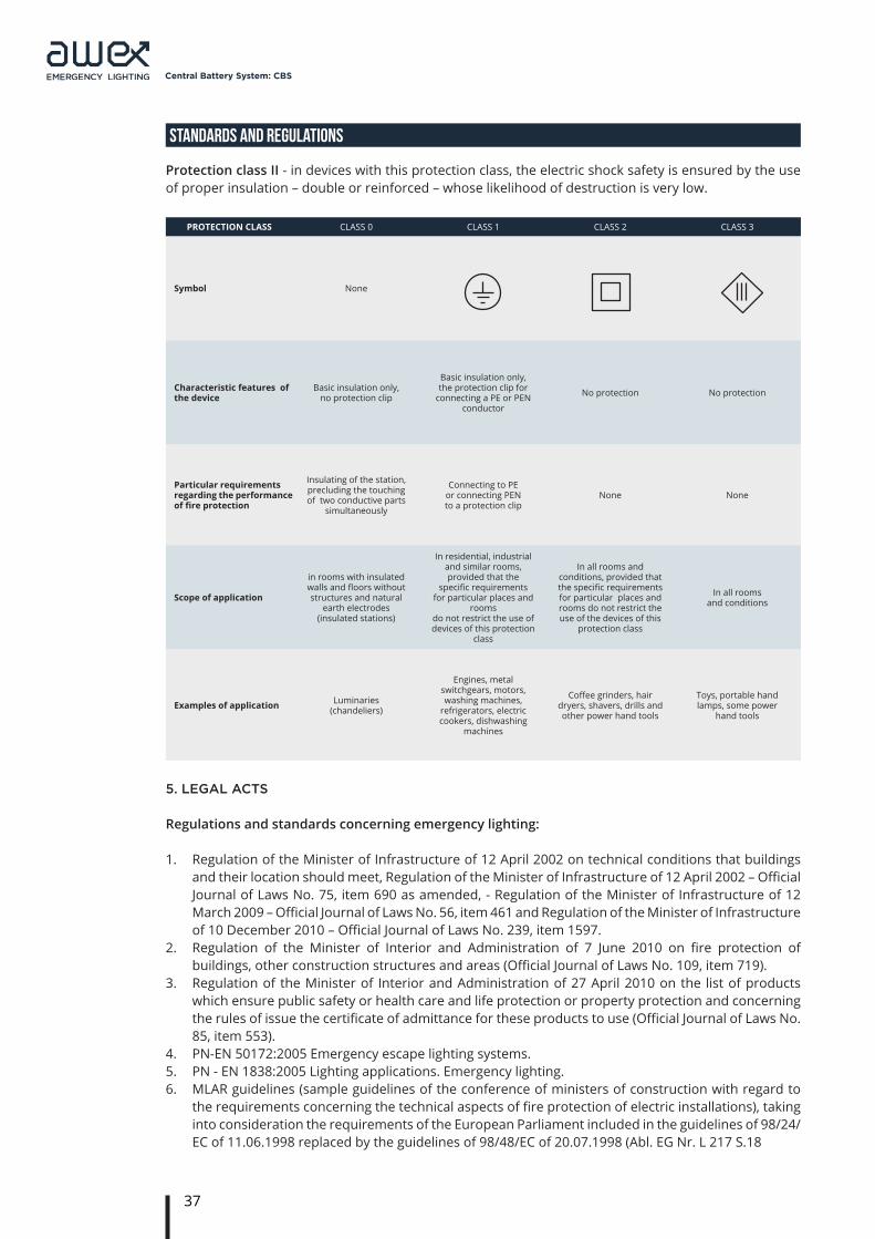
Protection class II - in devices with this protection class, the electric shock safety is ensured by the use of proper insulation – double or reinforced – whose likelihood of destruction is very low.
PROTECTION CLASS CLASS 0 CLASS 1 CLASS 2 CLASS 3
Symbol None
Characteristic features of the device
Basic insulation only, no protection clip
Basic insulation only, the protection clip for
connecting a PE or PEN conductor
No protection No protection
Particular requirements regarding the performance of fire protection
Insulating of the station, precluding the touching of two conductive parts
simultaneously
Connecting to PE or connecting PEN to a protection clip
None None
Scope of application
in rooms with insulated walls and floors without structures and natural
earth electrodes (insulated stations)
In residential, industrial and similar rooms, provided that the
specific requirements for particular places and
rooms do not restrict the use of devices of this protection
class
In all rooms and conditions, provided that the specific requirements for particular places and rooms do not restrict the use of the devices of this
protection class
In all rooms and conditions
Examples of application Luminaries (chandeliers)
Engines, metal switchgears, motors, washing machines,
refrigerators, electric cookers, dishwashing
machines
Coffee grinders, hair dryers, shavers, drills and other power hand tools
Toys, portable hand lamps, some power
hand tools
5. legal acts
Regulations and standards concerning emergency lighting:
1. Regulation of the Minister of Infrastructure of 12 April 2002 on technical conditions that buildings and their location should meet, Regulation of the Minister of Infrastructure of 12 April 2002 – Official Journal of Laws No. 75, item 690 as amended, - Regulation of the Minister of Infrastructure of 12 March 2009 – Official Journal of Laws No. 56, item 461 and Regulation of the Minister of Infrastructure of 10 December 2010 – Official Journal of Laws No. 239, item 1597.
2. Regulation of the Minister of Interior and Administration of 7 June 2010 on fire protection of buildings, other construction structures and areas (Official Journal of Laws No. 109, item 719).
3. Regulation of the Minister of Interior and Administration of 27 April 2010 on the list of products which ensure public safety or health care and life protection or property protection and concerning the rules of issue the certificate of admittance for these products to use (Official Journal of Laws No. 85, item 553).
4. PN-EN 50172:2005 Emergency escape lighting systems.5. PN - EN 1838:2005 Lighting applications. Emergency lighting.6. MLAR guidelines (sample guidelines of the conference of ministers of construction with regard to
the requirements concerning the technical aspects of fire protection of electric installations), taking into consideration the requirements of the European Parliament included in the guidelines of 98/24/EC of 11.06.1998 replaced by the guidelines of 98/48/EC of 20.07.1998 (Abl. EG Nr. L 217 S.18

38
Central Battery System: CBS
STANDARDS AND REGULATIONS
In addition, provisions of the following standards should be used during the design:
• PN-EN 60598-2-22:2004/AC Luminaires – Part 2-22: Particular requirements – Luminaires for emergency lighting
• HD 384/HD 60364 PN-IEC 60364:1999 (multi-part standard) Electrical installations of buildings.• PN-EN 13032-1:2005 Light and lighting.
Measurement and presentation of photometric data of lamps and luminaires.
Part 1: Measurement and file format
• PN-EN 13032-2:2005 Light and lighting. Measurement and presentation of photometric data of lamps and luminaires.
Part 2: Presentation of data for indoor and outdoor work places
• PN-EN 12464-1:2004 Light and lighting – Lighting of work places – Part 1: Indoor work places• PN-EN 50171:2007: Central power supply systems• PN-EN 50272-2:2007: Safety requirements for secondary batteries and battery installations - Part 2:
Stationary batteries• PN-EN 60529:2003 Degrees of protection provided by enclosures (IP Code)• PN-EN 61347:2005 (multi-part standard) Lamp controlgear – Part 2-7: Particular requirements for
battery supplied electronic controlgear for emergency lighting• PN-EN 60617-11:2004 Graphical symbols for diagrams – Part 11: Architectural and topographical
installation plans and diagrams• PN-N-01256-5:1998 Safety signs. Principles for location of safety signs on fire-fighting and escape
routes.• PN-N-01255:1992 Safety colours and safety signs.

39
Central Battery System: CBS
NOTES