Embed Size (px)
Citation preview
1Central Processing Unit
Computer Organization Computer Architectures Lab
CENTRAL PROCESSING UNIT
• Introduction
• General Register Organization
• Stack Organization
• Instruction Formats
• Addressing Modes
• Data Transfer and Manipulation
• Program Control
• Reduced Instruction Set Computer
2Central Processing Unit
Computer Organization Computer Architectures Lab
MAJOR COMPONENTS OF CPU
Introduction
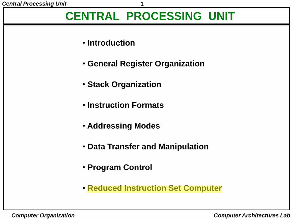
• Storage ComponentsRegisters
Flags
• Execution (Processing) ComponentsArithmetic Logic Unit(ALU)
Arithmetic calculations, Logical computations, Shifts/Rotates
• Transfer ComponentsBus
• Control ComponentsControl Unit Register
File ALU
Control Unit
3Central Processing Unit
Computer Organization Computer Architectures Lab
REGISTERS
• In Basic Computer, there is only one general purpose register, the Accumulator (AC)
• In modern CPUs, there are many general purpose registers
• It is advantageous to have many registers
– Transfer between registers within the processor are relatively fast
– Going “off the processor” to access memory is much slower
• How many registers will be the best ?
4Central Processing Unit
Computer Organization Computer Architectures Lab
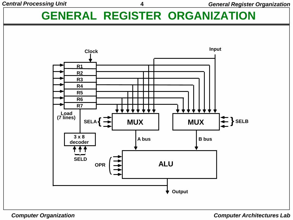
GENERAL REGISTER ORGANIZATIONGeneral Register Organization
MUXSELA{ MUX } SELB
ALUOPR
R1
R2
R3
R4
R5
R6
R7
Input
3 x 8decoder
SELD
Load(7 lines)
Output
A bus B bus
Clock
5Central Processing Unit
Computer Organization Computer Architectures Lab
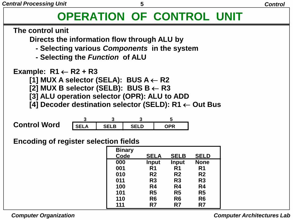
OPERATION OF CONTROL UNITThe control unit
Directs the information flow through ALU by
- Selecting various Components in the system
- Selecting the Function of ALU
Example: R1 R2 + R3[1] MUX A selector (SELA): BUS A R2[2] MUX B selector (SELB): BUS B R3[3] ALU operation selector (OPR): ALU to ADD[4] Decoder destination selector (SELD): R1 Out Bus
Control Word
Encoding of register selection fields
Control
BinaryCode SELA SELB SELD000 Input Input None001 R1 R1 R1010 R2 R2 R2011 R3 R3 R3100 R4 R4 R4101 R5 R5 R5110 R6 R6 R6111 R7 R7 R7
SELA SELB SELD OPR
3 3 3 5
6Central Processing Unit
Computer Organization Computer Architectures Lab
ALU CONTROL
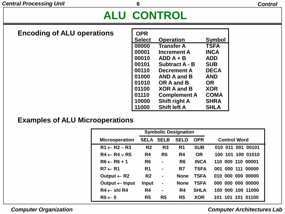
Encoding of ALU operations OPRSelect Operation Symbol00000 Transfer A TSFA00001 Increment A INCA00010 ADD A + B ADD00101 Subtract A - B SUB00110 Decrement A DECA01000 AND A and B AND01010 OR A and B OR01100 XOR A and B XOR01110 Complement A COMA10000 Shift right A SHRA11000 Shift left A SHLA
Examples of ALU Microoperations
Symbolic Designation
Microoperation SELA SELB SELD OPR Control Word
Control
R1 R2 R3 R2 R3 R1 SUB 010 011 001 00101
R4 R4 R5 R4 R5 R4 OR 100 101 100 01010
R6 R6 + 1 R6 - R6 INCA 110 000 110 00001
R7 R1 R1 - R7 TSFA 001 000 111 00000
Output R2 R2 - None TSFA 010 000 000 00000
Output Input Input - None TSFA 000 000 000 00000
R4 shl R4 R4 - R4 SHLA 100 000 100 11000
R5 0 R5 R5 R5 XOR 101 101 101 01100
7Central Processing Unit
Computer Organization Computer Architectures Lab
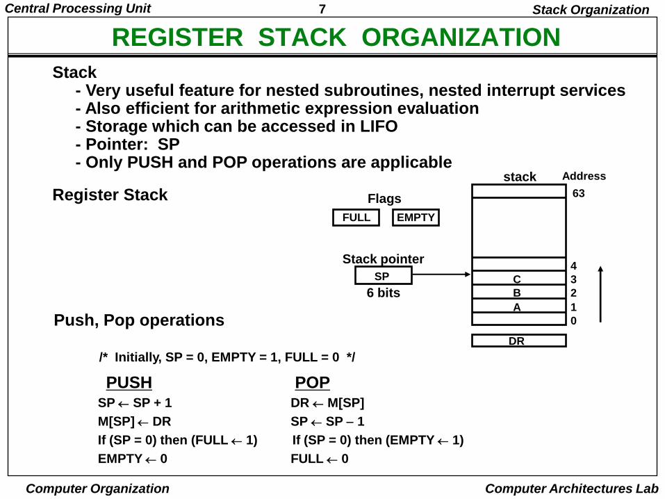
REGISTER STACK ORGANIZATION
Register Stack
Push, Pop operations
/* Initially, SP = 0, EMPTY = 1, FULL = 0 */
PUSH POP
Stack Organization
SP SP + 1 DR M[SP]
M[SP] DR SP SP 1
If (SP = 0) then (FULL 1) If (SP = 0) then (EMPTY 1)
EMPTY 0 FULL 0
Stack- Very useful feature for nested subroutines, nested interrupt services- Also efficient for arithmetic expression evaluation- Storage which can be accessed in LIFO- Pointer: SP- Only PUSH and POP operations are applicable
A
B
C
0
1
2
3
4
63
Address
FULL EMPTY
SP
DR
Flags
Stack pointer
stack
6 bits
8Central Processing Unit
Computer Organization Computer Architectures Lab
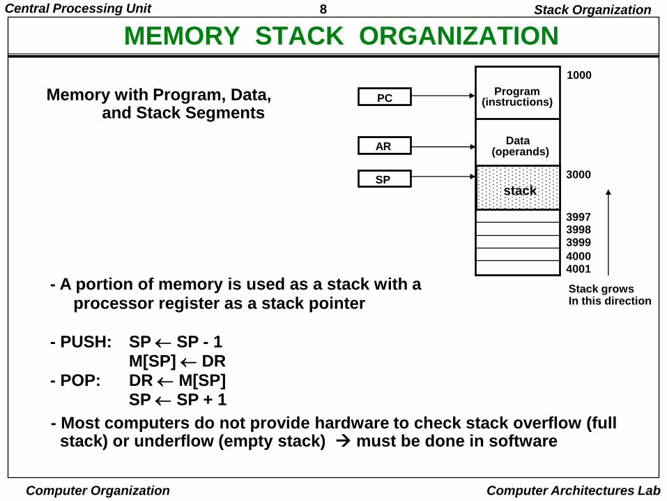
MEMORY STACK ORGANIZATIONStack Organization
- A portion of memory is used as a stack with a processor register as a stack pointer
- PUSH: SP SP - 1M[SP] DR
- POP: DR M[SP]SP SP + 1
Memory with Program, Data, and Stack Segments
40014000
399939983997
3000
Data(operands)
Program(instructions)
1000
PC
AR
SPstack
Stack growsIn this direction
- Most computers do not provide hardware to check stack overflow (full stack) or underflow (empty stack) must be done in software
9Central Processing Unit
Computer Organization Computer Architectures Lab
REVERSE POLISH NOTATION
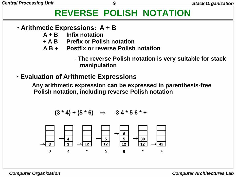
A + B Infix notation+ A B Prefix or Polish notationA B + Postfix or reverse Polish notation
- The reverse Polish notation is very suitable for stack manipulation
• Evaluation of Arithmetic Expressions
Any arithmetic expression can be expressed in parenthesis-free Polish notation, including reverse Polish notation
(3 * 4) + (5 * 6) 3 4 * 5 6 * +
Stack Organization
• Arithmetic Expressions: A + B
3 3 12 12 12 12 42
4 5 5
6
30
3 4 * 5 6 * +
10Central Processing Unit
Computer Organization Computer Architectures Lab
PROCESSOR ORGANIZATION
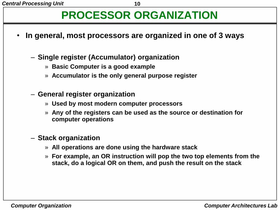
• In general, most processors are organized in one of 3 ways
– Single register (Accumulator) organization
» Basic Computer is a good example
» Accumulator is the only general purpose register
– General register organization
» Used by most modern computer processors
» Any of the registers can be used as the source or destination for computer operations
– Stack organization
» All operations are done using the hardware stack
» For example, an OR instruction will pop the two top elements from the stack, do a logical OR on them, and push the result on the stack
11Central Processing Unit
Computer Organization Computer Architectures Lab
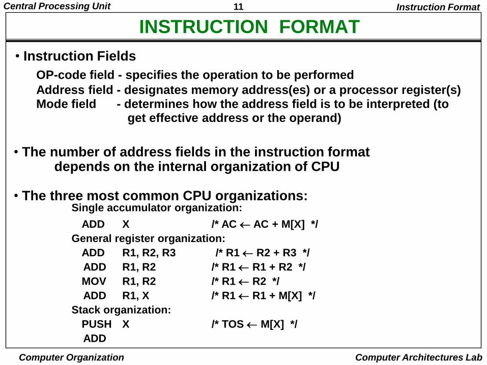
INSTRUCTION FORMAT
OP-code field - specifies the operation to be performed
Address field - designates memory address(es) or a processor register(s)Mode field - determines how the address field is to be interpreted (to
get effective address or the operand)
• The number of address fields in the instruction format depends on the internal organization of CPU
• The three most common CPU organizations:
Instruction Format
Single accumulator organization:
ADD X /* AC AC + M[X] */
General register organization:
ADD R1, R2, R3 /* R1 R2 + R3 */
ADD R1, R2 /* R1 R1 + R2 */
MOV R1, R2 /* R1 R2 */
ADD R1, X /* R1 R1 + M[X] */
Stack organization:
PUSH X /* TOS M[X] */
ADD
• Instruction Fields
12Central Processing Unit
Computer Organization Computer Architectures Lab
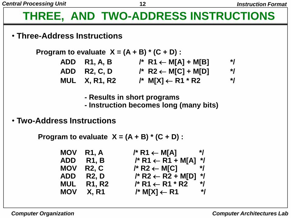
• Three-Address Instructions
Program to evaluate X = (A + B) * (C + D) :
ADD R1, A, B /* R1 M[A] + M[B] */
ADD R2, C, D /* R2 M[C] + M[D] */
MUL X, R1, R2 /* M[X] R1 * R2 */
- Results in short programs - Instruction becomes long (many bits)
• Two-Address Instructions
Program to evaluate X = (A + B) * (C + D) :
MOV R1, A /* R1 M[A] */ADD R1, B /* R1 R1 + M[A] */MOV R2, C /* R2 M[C] */ADD R2, D /* R2 R2 + M[D] */MUL R1, R2 /* R1 R1 * R2 */MOV X, R1 /* M[X] R1 */
Instruction Format
THREE, AND TWO-ADDRESS INSTRUCTIONS
13Central Processing Unit
Computer Organization Computer Architectures Lab
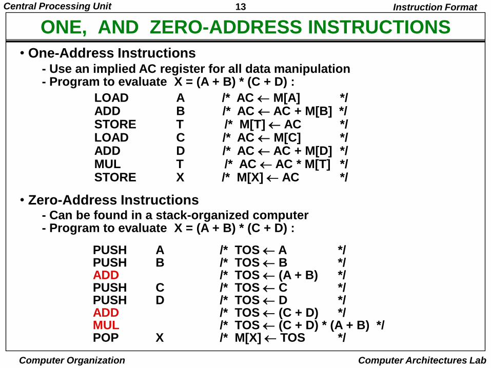
ONE, AND ZERO-ADDRESS INSTRUCTIONS
• One-Address Instructions- Use an implied AC register for all data manipulation- Program to evaluate X = (A + B) * (C + D) :
Instruction Format
LOAD A /* AC M[A] */ADD B /* AC AC + M[B] */STORE T /* M[T] AC */LOAD C /* AC M[C] */ADD D /* AC AC + M[D] */MUL T /* AC AC * M[T] */STORE X /* M[X] AC */
• Zero-Address Instructions- Can be found in a stack-organized computer- Program to evaluate X = (A + B) * (C + D) :
PUSH A /* TOS A */PUSH B /* TOS B */ADD /* TOS (A + B) */PUSH C /* TOS C */PUSH D /* TOS D */ADD /* TOS (C + D) */MUL /* TOS (C + D) * (A + B) */ POP X /* M[X] TOS */

14Central Processing Unit
Computer Organization Computer Architectures Lab
ADDRESSING MODES
Addressing Modes
• Addressing Modes
* Specifies a rule for interpreting or modifying the address field of the instruction (before the operand is actually referenced)
* Variety of addressing modes
- to give programming flexibility to the user- to use the bits in the address field of the
instruction efficiently
15Central Processing Unit
Computer Organization Computer Architectures Lab
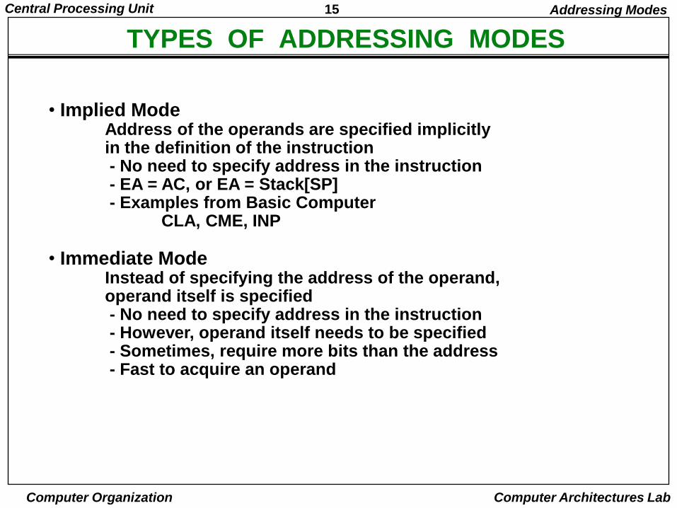
TYPES OF ADDRESSING MODES
• Implied ModeAddress of the operands are specified implicitly in the definition of the instruction- No need to specify address in the instruction- EA = AC, or EA = Stack[SP]- Examples from Basic Computer
CLA, CME, INP
• Immediate ModeInstead of specifying the address of the operand,operand itself is specified- No need to specify address in the instruction- However, operand itself needs to be specified- Sometimes, require more bits than the address- Fast to acquire an operand
Addressing Modes
16Central Processing Unit
Computer Organization Computer Architectures Lab
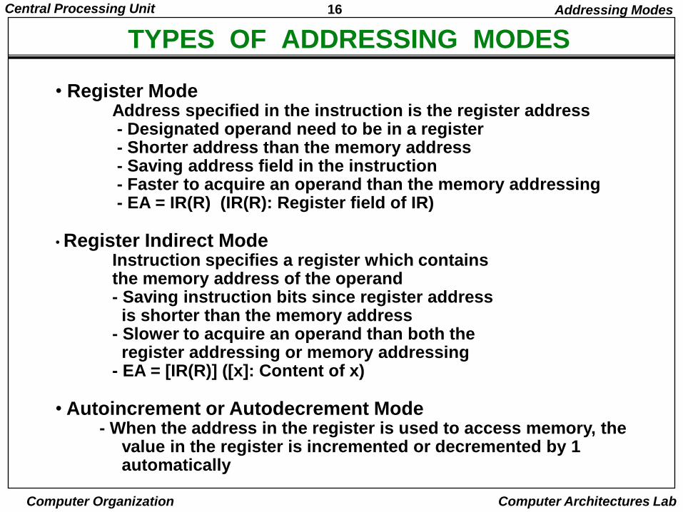
TYPES OF ADDRESSING MODES
• Register ModeAddress specified in the instruction is the register address- Designated operand need to be in a register- Shorter address than the memory address- Saving address field in the instruction- Faster to acquire an operand than the memory addressing- EA = IR(R) (IR(R): Register field of IR)
• Register Indirect ModeInstruction specifies a register which containsthe memory address of the operand - Saving instruction bits since register addressis shorter than the memory address
- Slower to acquire an operand than both the register addressing or memory addressing
- EA = [IR(R)] ([x]: Content of x)
• Autoincrement or Autodecrement Mode- When the address in the register is used to access memory, the
value in the register is incremented or decremented by 1 automatically
Addressing Modes
17Central Processing Unit
Computer Organization Computer Architectures Lab
TYPES OF ADDRESSING MODES
Addressing Modes
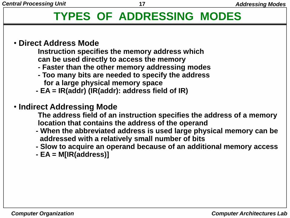
• Direct Address ModeInstruction specifies the memory address whichcan be used directly to access the memory- Faster than the other memory addressing modes- Too many bits are needed to specify the address
for a large physical memory space- EA = IR(addr) (IR(addr): address field of IR)
• Indirect Addressing ModeThe address field of an instruction specifies the address of a memory location that contains the address of the operand
- When the abbreviated address is used large physical memory can be addressed with a relatively small number of bits
- Slow to acquire an operand because of an additional memory access- EA = M[IR(address)]
18Central Processing Unit
Computer Organization Computer Architectures Lab
TYPES OF ADDRESSING MODES
Addressing Modes
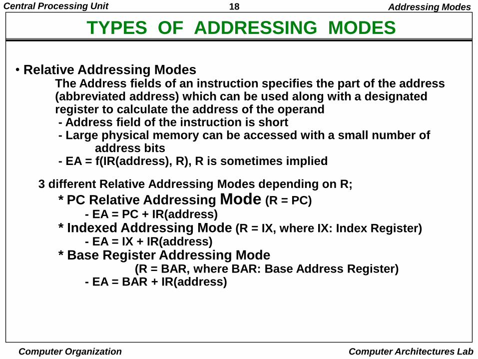
• Relative Addressing ModesThe Address fields of an instruction specifies the part of the address (abbreviated address) which can be used along with a designated register to calculate the address of the operand- Address field of the instruction is short- Large physical memory can be accessed with a small number of
address bits- EA = f(IR(address), R), R is sometimes implied
3 different Relative Addressing Modes depending on R;
* PC Relative Addressing Mode (R = PC)- EA = PC + IR(address)
* Indexed Addressing Mode (R = IX, where IX: Index Register)- EA = IX + IR(address)
* Base Register Addressing Mode(R = BAR, where BAR: Base Address Register)
- EA = BAR + IR(address)
19Central Processing Unit
Computer Organization Computer Architectures Lab
ADDRESSING MODES - EXAMPLES -
AddressingMode
EffectiveAddress
Contentof AC
Addressing Modes
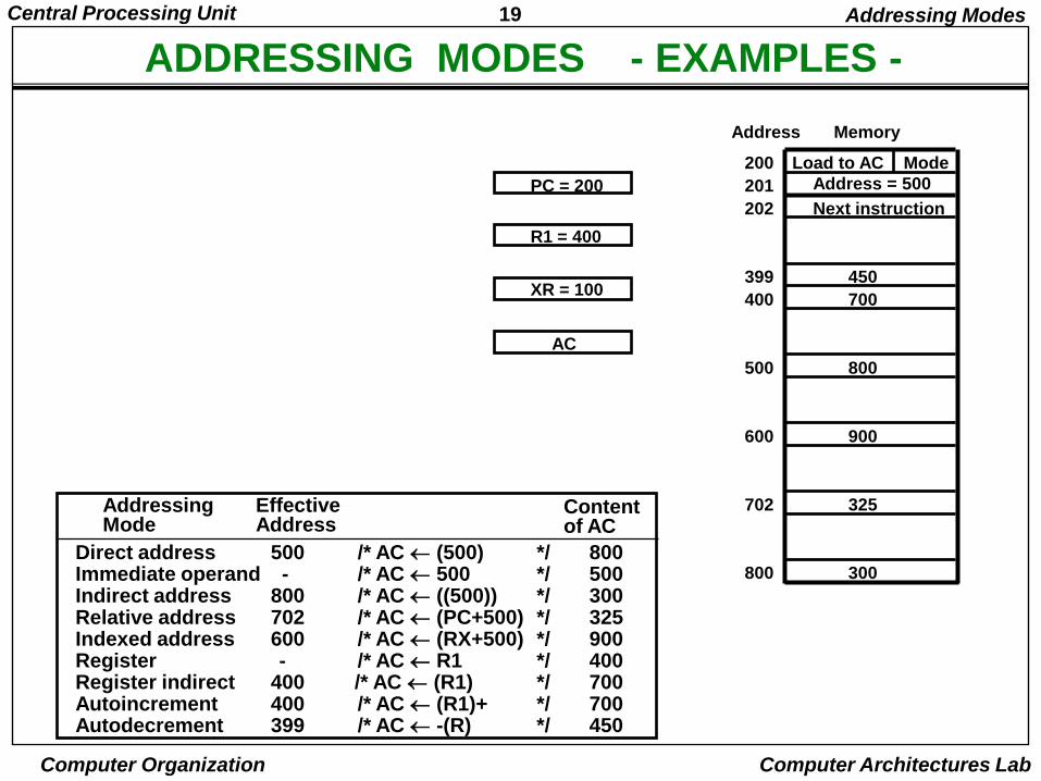
Direct address 500 /* AC (500) */ 800Immediate operand - /* AC 500 */ 500Indirect address 800 /* AC ((500)) */ 300Relative address 702 /* AC (PC+500) */ 325Indexed address 600 /* AC (RX+500) */ 900Register - /* AC R1 */ 400Register indirect 400 /* AC (R1) */ 700Autoincrement 400 /* AC (R1)+ */ 700Autodecrement 399 /* AC -(R) */ 450
Load to AC Mode
Address = 500
Next instruction
200
201
202
399
400
450
700
500 800
600 900
702 325
800 300
MemoryAddress
PC = 200
R1 = 400
XR = 100
AC
20Central Processing Unit
Computer Organization Computer Architectures Lab
DATA TRANSFER INSTRUCTIONS
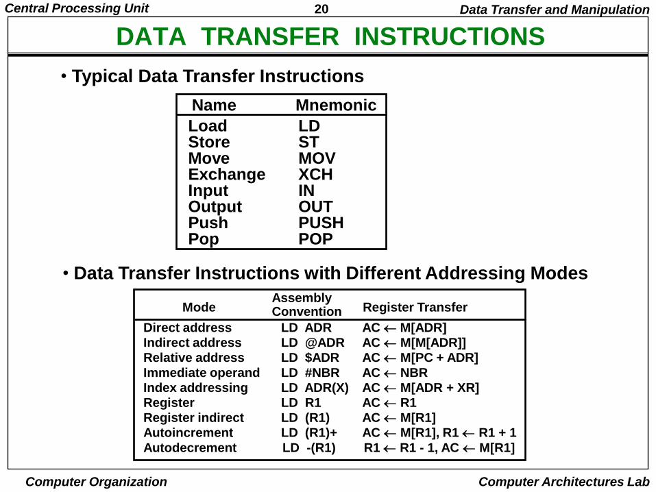
Load LDStore STMove MOVExchange XCHInput INOutput OUTPush PUSHPop POP
Name Mnemonic
• Typical Data Transfer Instructions
Direct address LD ADR AC M[ADR]Indirect address LD @ADR AC M[M[ADR]]Relative address LD $ADR AC M[PC + ADR]
Immediate operand LD #NBR AC NBRIndex addressing LD ADR(X) AC M[ADR + XR]Register LD R1 AC R1
Register indirect LD (R1) AC M[R1]Autoincrement LD (R1)+ AC M[R1], R1 R1 + 1
Autodecrement LD -(R1) R1 R1 - 1, AC M[R1]
ModeAssemblyConvention Register Transfer
Data Transfer and Manipulation
• Data Transfer Instructions with Different Addressing Modes
21Central Processing Unit
Computer Organization Computer Architectures Lab
DATA MANIPULATION INSTRUCTIONS
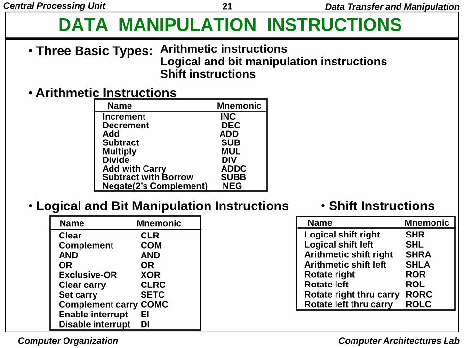
• Three Basic Types: Arithmetic instructionsLogical and bit manipulation instructionsShift instructions
• Arithmetic InstructionsName Mnemonic
Clear CLRComplement COMAND ANDOR ORExclusive-OR XORClear carry CLRCSet carry SETCComplement carry COMCEnable interrupt EIDisable interrupt DI
Name Mnemonic
Logical shift right SHRLogical shift left SHLArithmetic shift right SHRAArithmetic shift left SHLARotate right RORRotate left ROLRotate right thru carry RORCRotate left thru carry ROLC
Name Mnemonic
• Logical and Bit Manipulation Instructions • Shift Instructions
Data Transfer and Manipulation
Increment INCDecrement DECAdd ADDSubtract SUBMultiply MULDivide DIVAdd with Carry ADDCSubtract with Borrow SUBBNegate(2‟s Complement) NEG
22Central Processing Unit
Computer Organization Computer Architectures Lab
FLAG, PROCESSOR STATUS WORD
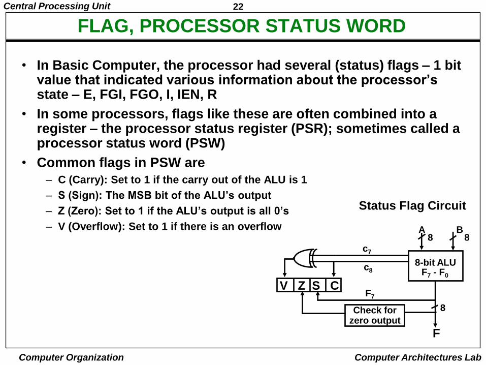
• In Basic Computer, the processor had several (status) flags – 1 bit value that indicated various information about the processor‟s state – E, FGI, FGO, I, IEN, R
• In some processors, flags like these are often combined into a register – the processor status register (PSR); sometimes called a processor status word (PSW)
• Common flags in PSW are
– C (Carry): Set to 1 if the carry out of the ALU is 1
– S (Sign): The MSB bit of the ALU‟s output
– Z (Zero): Set to 1 if the ALU‟s output is all 0‟s
– V (Overflow): Set to 1 if there is an overflow
Status Flag Circuit
c7
c8
A B8 8
8-bit ALU
V Z S CF7
F7 - F0
8
F
Check forzero output
23Central Processing Unit
Computer Organization Computer Architectures Lab
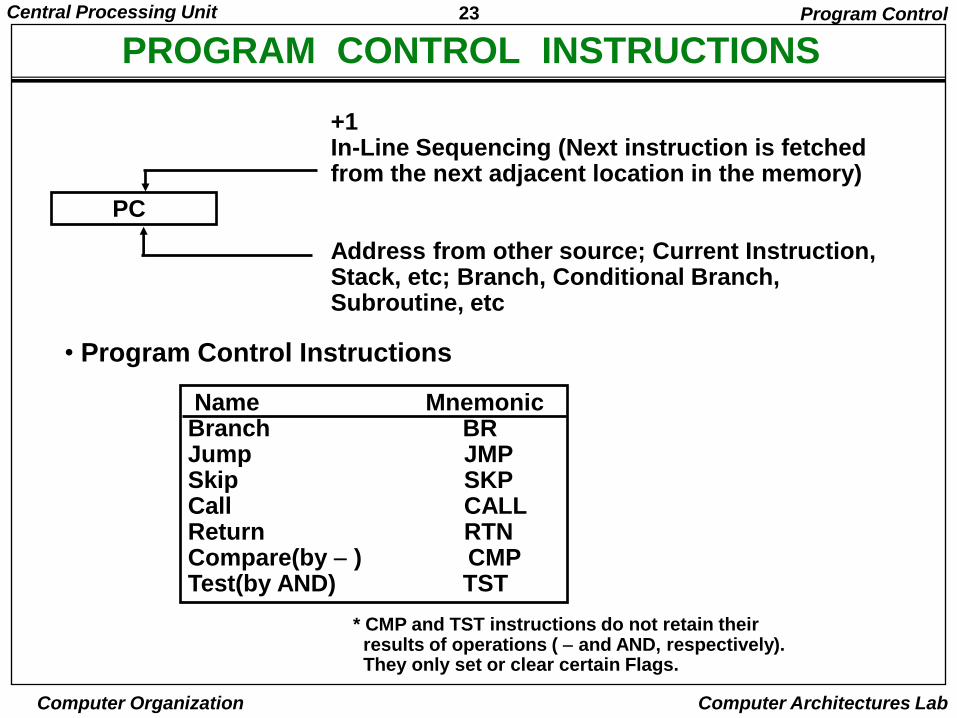
PROGRAM CONTROL INSTRUCTIONSProgram Control
PC
+1In-Line Sequencing (Next instruction is fetched from the next adjacent location in the memory)
Address from other source; Current Instruction, Stack, etc; Branch, Conditional Branch, Subroutine, etc
• Program Control Instructions
Name MnemonicBranch BRJump JMPSkip SKPCall CALLReturn RTNCompare(by ) CMPTest(by AND) TST
* CMP and TST instructions do not retain their results of operations ( and AND, respectively).They only set or clear certain Flags.
24Central Processing Unit
Computer Organization Computer Architectures Lab
CONDITIONAL BRANCH INSTRUCTIONS
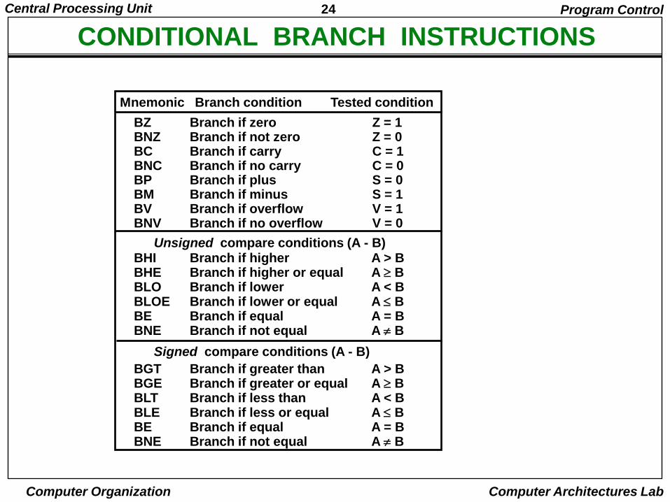
BZ Branch if zero Z = 1BNZ Branch if not zero Z = 0BC Branch if carry C = 1BNC Branch if no carry C = 0BP Branch if plus S = 0BM Branch if minus S = 1BV Branch if overflow V = 1BNV Branch if no overflow V = 0
BHI Branch if higher A > BBHE Branch if higher or equal A BBLO Branch if lower A < BBLOE Branch if lower or equal A BBE Branch if equal A = BBNE Branch if not equal A B
BGT Branch if greater than A > BBGE Branch if greater or equal A BBLT Branch if less than A < BBLE Branch if less or equal A BBE Branch if equal A = BBNE Branch if not equal A B
Unsigned compare conditions (A - B)
Signed compare conditions (A - B)
Mnemonic Branch condition Tested condition
Program Control
25Central Processing Unit
Computer Organization Computer Architectures Lab
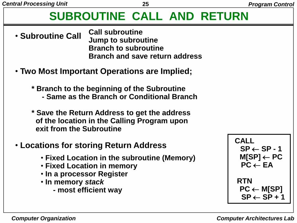
SUBROUTINE CALL AND RETURN
Call subroutineJump to subroutineBranch to subroutineBranch and save return address
• Fixed Location in the subroutine (Memory)• Fixed Location in memory• In a processor Register• In memory stack
- most efficient way
Program Control
• Subroutine Call
• Two Most Important Operations are Implied;
* Branch to the beginning of the Subroutine- Same as the Branch or Conditional Branch
* Save the Return Address to get the addressof the location in the Calling Program uponexit from the Subroutine
• Locations for storing Return AddressCALL
SP SP - 1M[SP] PCPC EA
RTNPC M[SP]SP SP + 1
26Central Processing Unit
Computer Organization Computer Architectures Lab
PROGRAM INTERRUPT
Types of Interrupts
External interruptsExternal Interrupts initiated from the outside of CPU and Memory- I/O Device → Data transfer request or Data transfer complete- Timing Device → Timeout- Power Failure - Operator
Internal interrupts (traps)Internal Interrupts are caused by the currently running program - Register, Stack Overflow- Divide by zero- OP-code Violation- Protection Violation
Software InterruptsBoth External and Internal Interrupts are initiated by the computer HW.Software Interrupts are initiated by the executing an instruction.- Supervisor Call → Switching from a user mode to the supervisor mode
→ Allows to execute a certain class of operationswhich are not allowed in the user mode
Program Control
27Central Processing Unit
Computer Organization Computer Architectures Lab
INTERRUPT PROCEDURE
- The interrupt is usually initiated by an internal oran external signal rather than from the execution of an instruction (except for the software interrupt)
- The address of the interrupt service program is determined by the hardware rather than from the address field of an instruction
- An interrupt procedure usually stores all the information necessary to define the state of CPU rather than storing only the PC.
The state of the CPU is determined from;Content of the PCContent of all processor registersContent of status bits
Many ways of saving the CPU state depending on the CPU architectures
Program Control
Interrupt Procedure and Subroutine Call
28Central Processing Unit
Computer Organization Computer Architectures Lab
RISC: Historical BackgroundRIS
C
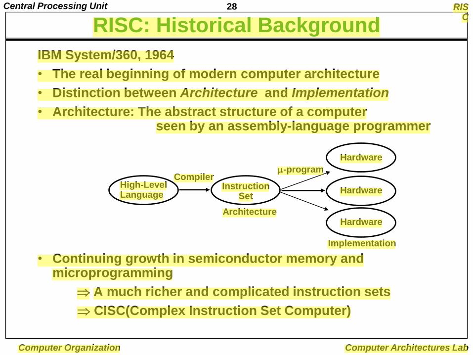
IBM System/360, 1964
• The real beginning of modern computer architecture
• Distinction between Architecture and Implementation
• Architecture: The abstract structure of a computer seen by an assembly-language programmer
• Continuing growth in semiconductor memory and microprogramming
A much richer and complicated instruction sets
CISC(Complex Instruction Set Computer)
High-LevelLanguage
InstructionSet
Hardware
Compiler-program
Architecture
Implementation
Hardware
Hardware
29Central Processing Unit
Computer Organization Computer Architectures Lab
ARGUMENTS ADVANCED AT THAT TIME
• Richer instruction sets would simplify compilers
• Richer instruction sets would alleviate the software crisis
– move as much functions to the hardware as possible
• Richer instruction sets would improve architecture quality
30Central Processing Unit
Computer Organization Computer Architectures Lab
ARCHITECTURE DESIGN PRINCIPLES - IN 70‟s -
RISC
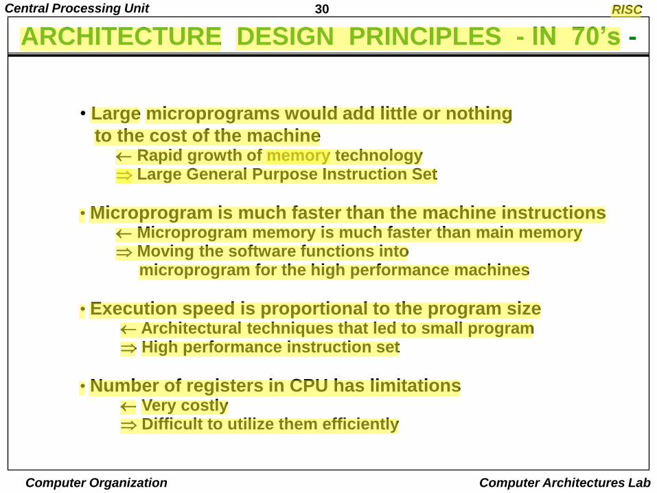
• Large microprograms would add little or nothing
to the cost of the machine Rapid growth of memory technology Large General Purpose Instruction Set
• Microprogram is much faster than the machine instructions Microprogram memory is much faster than main memory Moving the software functions into
microprogram for the high performance machines
• Execution speed is proportional to the program size Architectural techniques that led to small program High performance instruction set
• Number of registers in CPU has limitations Very costly Difficult to utilize them efficiently

31Central Processing Unit
Computer Organization Computer Architectures Lab
COMPARISONS OF EXECUTION MODELS
A B + C Data: 32-bit
RISC
Load rB B
Load rC C
Add rA
Store rA A
rB rC
Load B
Add C
Store A
Add B C A
• Register-to-register
• Memory-to-register
• Memory-to-memory
I = 104b; D = 96b; M = 200b
I = 72b; D = 96b; M = 168b
I = 56b; D = 96b; M = 152b
8 4 16
8 16
8 16 16 16
32Central Processing Unit
Computer Organization Computer Architectures Lab
RISC
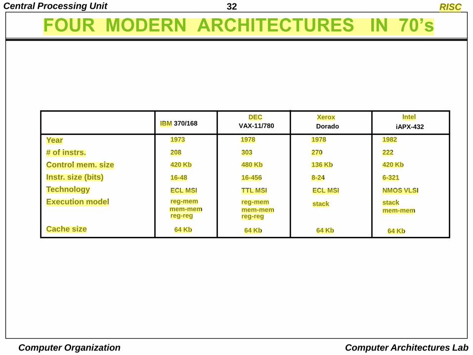
FOUR MODERN ARCHITECTURES IN 70‟s
Year
# of instrs.
Control mem. size
Instr. size (bits)
Technology
Execution model
Cache size
1973
208
420 Kb
16-48
ECL MSI
reg-mem
mem-memreg-reg
64 Kb
1978
303
480 Kb
16-456
TTL MSI
reg-mem
mem-memreg-reg
64 Kb
1978
270
136 Kb
8-24
ECL MSI
stack
64 Kb
1982
222
420 Kb
6-321
NMOS VLSI
stack
mem-mem
64 Kb
IBM 370/168 VAX-11/780 Dorado iAPX-432
DEC Xerox Intel
33Central Processing Unit
Computer Organization Computer Architectures Lab
COMPLEX INSTRUCTION SET COMPUTER
• These computers with many instructions and addressing modes came to be known as Complex Instruction Set Computers (CISC)
• One goal for CISC machines was to have a machine language instruction to match each high-level language statement type
34Central Processing Unit
Computer Organization Computer Architectures Lab
VARIABLE LENGTH INSTRUCTIONS
• The large number of instructions and addressing modes led CISC machines to have variable length instruction formats
• The large number of instructions means a greater number of bits to specify them
• In order to manage this large number of opcodes efficiently, they were encoded with different lengths:
– More frequently used instructions were encoded using short opcodes.
– Less frequently used ones were assigned longer opcodes.
• Also, multiple operand instructions could specify different addressing modes for each operand
– For example,
» Operand 1 could be a directly addressed register,
» Operand 2 could be an indirectly addressed memory location,
» Operand 3 (the destination) could be an indirectly addressed register.
• All of this led to the need to have different length instructions in different situations, depending on the opcode and operands used
35Central Processing Unit
Computer Organization Computer Architectures Lab
VARIABLE LENGTH INSTRUCTIONS
• For example, an instruction that only specifies register operands may only be two bytes in length
– One byte to specify the instruction and addressing mode
– One byte to specify the source and destination registers.
• An instruction that specifies memory addresses for operands may need five bytes
– One byte to specify the instruction and addressing mode
– Two bytes to specify each memory address
» Maybe more if there‟s a large amount of memory.
• Variable length instructions greatly complicate the fetch and decode problem for a processor
• The circuitry to recognize the various instructions and to properly fetch the required number of bytes for operands is very complex
36Central Processing Unit
Computer Organization Computer Architectures Lab
COMPLEX INSTRUCTION SET COMPUTER
• Another characteristic of CISC computers is that they have instructions that act directly on memory addresses
– For example, ADD L1, L2, L3
that takes the contents of M[L1] adds it to the contents of M[L2] and stores the result in location M[L3]
• An instruction like this takes three memory access cycles to execute
• That makes for a potentially very long instruction execution cycle
• The problems with CISC computers are
– The complexity of the design may slow down the processor,
– The complexity of the design may result in costly errors in the processor design and implementation,
– Many of the instructions and addressing modes are used rarely, if ever
37Central Processing Unit
Computer Organization Computer Architectures Lab
SUMMARY: CRITICISMS ON CISCRISC
High Performance General Purpose Instructions
- Complex Instruction→ Format, Length, Addressing Modes → Complicated instruction cycle control due to the complex
decoding HW and decoding process
- Multiple memory cycle instructions→ Operations on memory data→ Multiple memory accesses/instruction
- Microprogrammed control is necessity→ Microprogram control storage takes
substantial portion of CPU chip area→ Semantic Gap is large between machine
instruction and microinstruction
- General purpose instruction set includes all the features required by individually different applications→ When any one application is running, all the features
required by the other applications are extra burden to the application
38Central Processing Unit
Computer Organization Computer Architectures Lab
REDUCED INSTRUCTION SET COMPUTERS
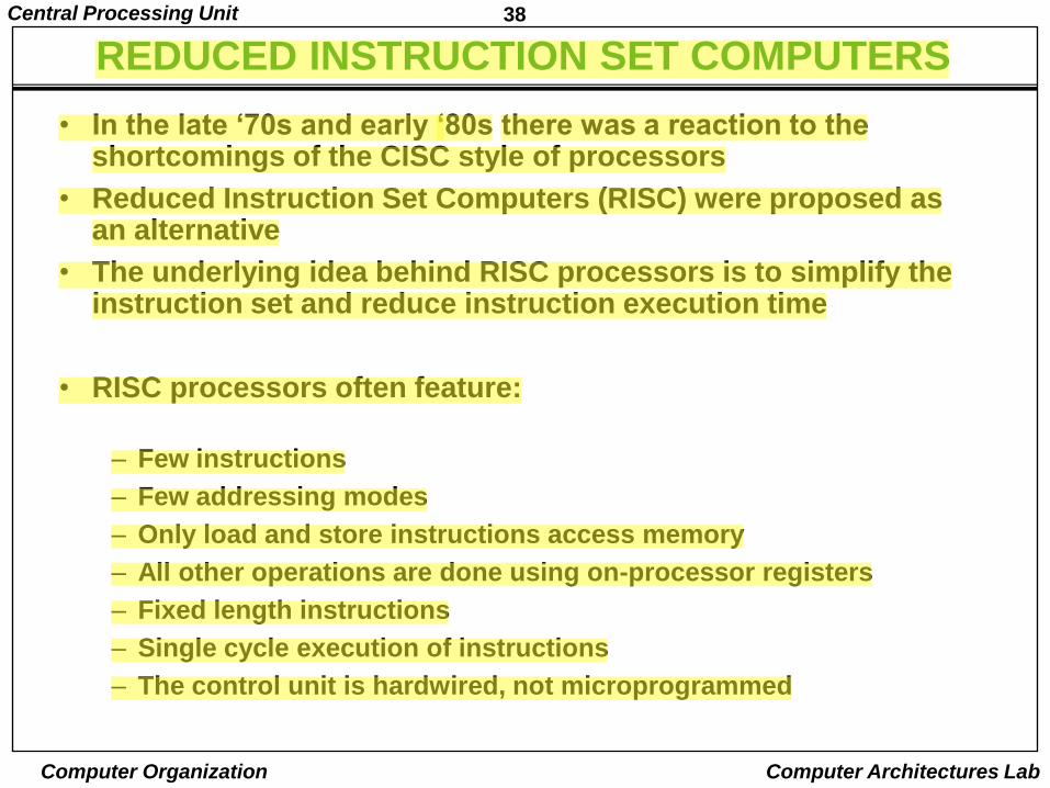
• In the late „70s and early „80s there was a reaction to the shortcomings of the CISC style of processors
• Reduced Instruction Set Computers (RISC) were proposed as an alternative
• The underlying idea behind RISC processors is to simplify the instruction set and reduce instruction execution time
• RISC processors often feature:
– Few instructions
– Few addressing modes
– Only load and store instructions access memory
– All other operations are done using on-processor registers
– Fixed length instructions
– Single cycle execution of instructions
– The control unit is hardwired, not microprogrammed
39Central Processing Unit
Computer Organization Computer Architectures Lab
REDUCED INSTRUCTION SET COMPUTERS
• Since all but the load and store instructions use only registers for operands, only a few addressing modes are needed
• By having all instructions the same length, reading them in is easy and fast
• The fetch and decode stages are simple, looking much more like Mano‟s Basic Computer than a CISC machine
• The instruction and address formats are designed to be easy to decode
• Unlike the variable length CISC instructions, the opcode and register fields of RISC instructions can be decoded simultaneously
• The control logic of a RISC processor is designed to be simple and fast
• The control logic is simple because of the small number of instructions and the simple addressing modes
• The control logic is hardwired, rather than microprogrammed, because hardwired control is faster
40Central Processing Unit
Computer Organization Computer Architectures Lab
ARCHITECTURAL METRIC
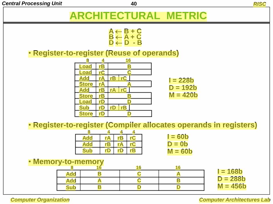
A B + CB A + CD D - B
RISC
• Register-to-register (Reuse of operands)
• Register-to-register (Compiler allocates operands in registers)
• Memory-to-memory
I = 228b D = 192b M = 420b
I = 60b D = 0b M = 60b
I = 168b D = 288b M = 456b
Load rB BLoad rC CAdd rAStore rA A
rB rC
8 4 16
Add rB rA rCStore rB BLoad rD DSub rD rD rBStore rD D
Add rA rB rC
Add rB rA rC
Sub rD rD rB
8 4 4 4
Add B C A
8 16 16 16
Add A C B
Sub B D D
41Central Processing Unit
Computer Organization Computer Architectures Lab
CHARACTERISTICS OF INITIAL RISC MACHINES
RISC
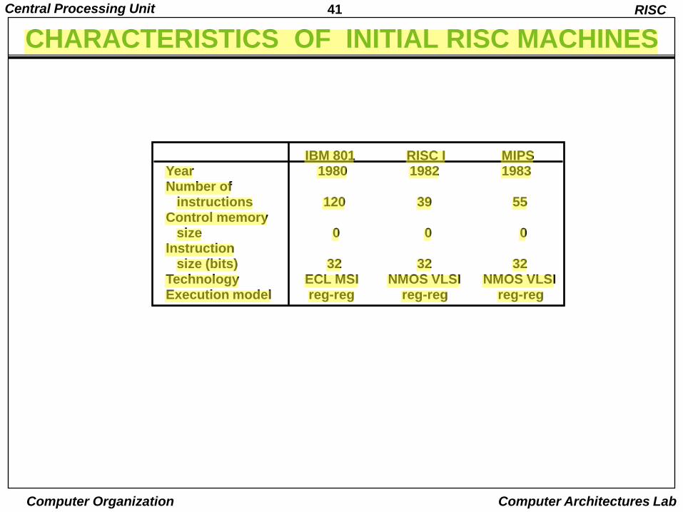
IBM 801 RISC I MIPSYear 1980 1982 1983Number of
instructions 120 39 55Control memory
size 0 0 0Instruction
size (bits) 32 32 32Technology ECL MSI NMOS VLSI NMOS VLSIExecution model reg-reg reg-reg reg-reg
42Central Processing Unit
Computer Organization Computer Architectures Lab
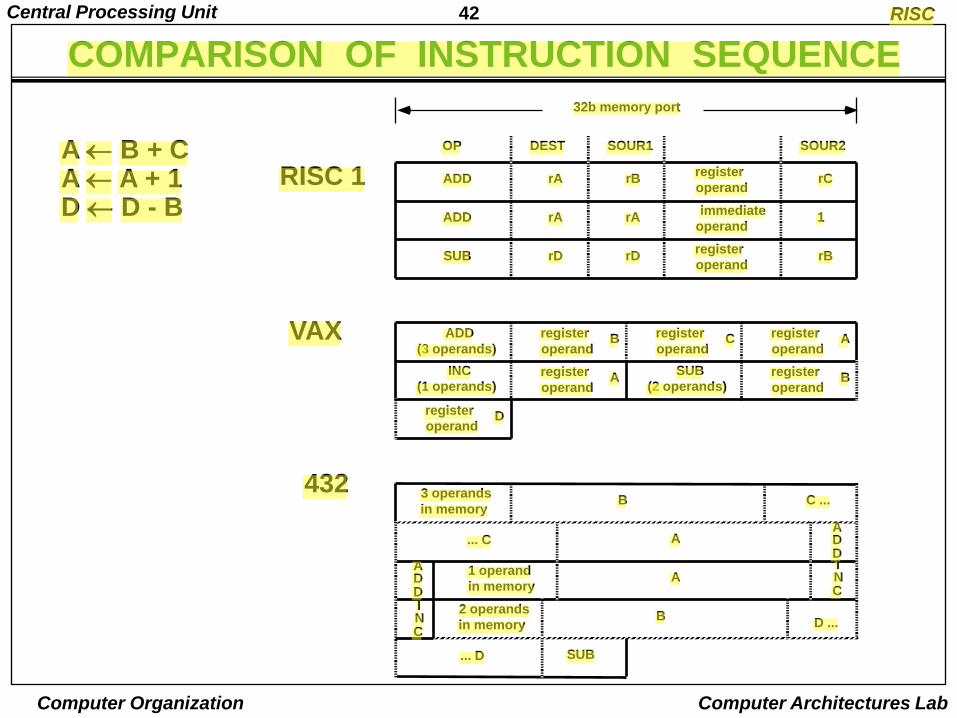
ADD rA rBregister
operandrC
OP DEST SOUR1 SOUR2
ADD rA rAimmediate
operand1
SUB rD rDregister
operandrB
32b memory port
ADD
(3 operands)
register
operandB register
operandC register
operandA
INC
(1 operands)register
operandA
SUB
(2 operands)register
operandB
register
operandD
3 operands
in memoryB C ...
... C AADD
ADD
1 operand
in memoryA
INC
INC
2 operands
in memory D ...B
... D SUB
RISC 1
VAX
432
RISC
COMPARISON OF INSTRUCTION SEQUENCE
A B + CA A + 1D D - B
43Central Processing Unit
Computer Organization Computer Architectures Lab
REGISTERS
• By simplifying the instructions and addressing modes, there is space available on the chip or board of a RISC CPU for more circuits than with a CISC processor
• This extra capacity is used to
– Pipeline instruction execution to speed up instruction execution
– Add a large number of registers to the CPU
44Central Processing Unit
Computer Organization Computer Architectures Lab
PIPELINING
• A very important feature of many RISC processors is the ability to execute an instruction each clock cycle
• This may seem nonsensical, since it takes at least once clock cycle each to fetch, decode and execute an instruction.
• It is however possible, because of a technique known as pipelining
– We‟ll study this in detail later
• Pipelining is the use of the processor to work on different phases of multiple instructions in parallel
45Central Processing Unit
Computer Organization Computer Architectures Lab
PIPELINING
• For instance, at one time, a pipelined processor may be
– Executing instruction it
– Decoding instruction it+1
– Fetching instruction it+2 from memory
• So, if we‟re running three instructions at once, and it takes an average instruction three cycles to run, the CPU is executing an average of an instruction a clock cycle
• As we‟ll see when we cover it in depth, there are complications
– For example, what happens to the pipeline when the processor branches
• However, pipelined execution is an integral part of all modern processors, and plays an important role
46Central Processing Unit
Computer Organization Computer Architectures Lab
REGISTERS
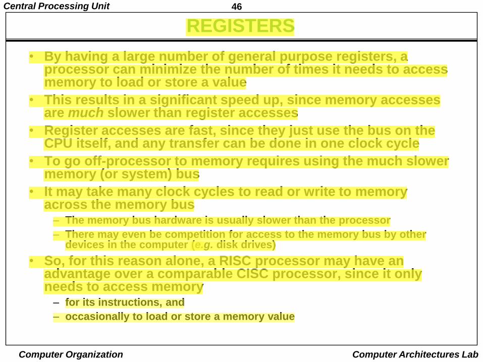
• By having a large number of general purpose registers, a processor can minimize the number of times it needs to access memory to load or store a value
• This results in a significant speed up, since memory accesses are much slower than register accesses
• Register accesses are fast, since they just use the bus on the CPU itself, and any transfer can be done in one clock cycle
• To go off-processor to memory requires using the much slower memory (or system) bus
• It may take many clock cycles to read or write to memory across the memory bus
– The memory bus hardware is usually slower than the processor
– There may even be competition for access to the memory bus by other devices in the computer (e.g. disk drives)
• So, for this reason alone, a RISC processor may have an advantage over a comparable CISC processor, since it only needs to access memory
– for its instructions, and
– occasionally to load or store a memory value
47Central Processing Unit
Computer Organization Computer Architectures Lab
UTILIZING RISC REGISTERS – REGISTER WINDOW
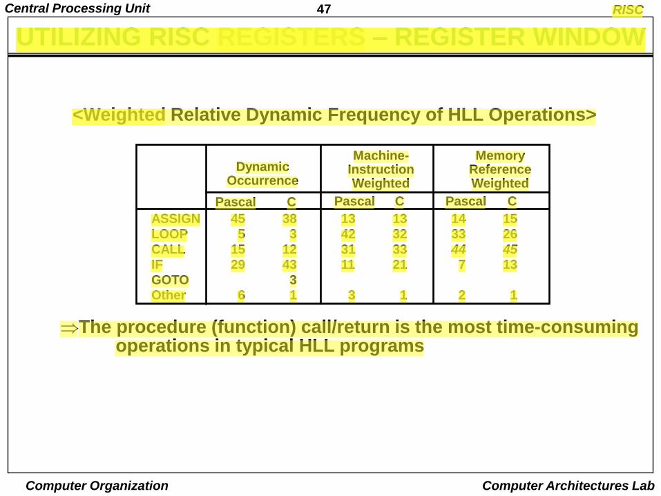
<Weighted Relative Dynamic Frequency of HLL Operations>
The procedure (function) call/return is the most time-consuming operations in typical HLL programs
RISC
Pascal C Pascal C Pascal C
DynamicOccurrence
Machine-InstructionWeighted
MemoryReferenceWeighted
ASSIGN 45 38 13 13 14 15
LOOP 5 3 42 32 33 26
CALL 15 12 31 33 44 45
IF 29 43 11 21 7 13
GOTO 3
Other 6 1 3 1 2 1
48Central Processing Unit
Computer Organization Computer Architectures Lab
RISC
CALL-RETURN BEHAVIOR
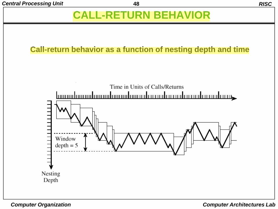
Call-return behavior as a function of nesting depth and time
49Central Processing Unit
Computer Organization Computer Architectures Lab
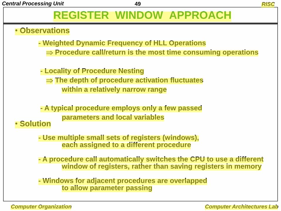
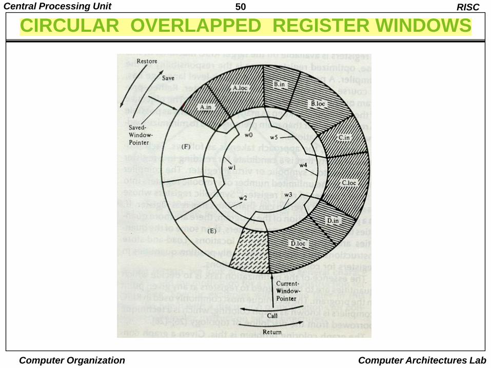
• Observations
- Weighted Dynamic Frequency of HLL Operations
Procedure call/return is the most time consuming operations
- Locality of Procedure Nesting
The depth of procedure activation fluctuates
within a relatively narrow range
- A typical procedure employs only a few passed
parameters and local variables• Solution
- Use multiple small sets of registers (windows), each assigned to a different procedure
- A procedure call automatically switches the CPU to use a different window of registers, rather than saving registers in memory
- Windows for adjacent procedures are overlapped to allow parameter passing
RISC
REGISTER WINDOW APPROACH
50Central Processing Unit
Computer Organization Computer Architectures Lab
CIRCULAR OVERLAPPED REGISTER WINDOWSRISC
51Central Processing Unit
Computer Organization Computer Architectures Lab
OVERLAPPED REGISTER WINDOWS
RISC
R15
R10
R15
R10
R25
R16
Common to D and A
Local to D
Common to C and D
Local to C
Common to B and C
Local to B
Common to A and B
Local to A
Common to A and D
Proc D
Proc C
Proc B
Proc AR9
R0
Common to allprocedures
Globalregisters
R31
R26
R9
R0
R15
R10
R25
R16
R31
R26
R41
R32
R47
R42
R57
R48
R63
R58
R73
R64
R25
R16
R31
R26
R15
R10
R25
R16
R31
R26
R15
R10
R25
R16
R31
R26
52Central Processing Unit
Computer Organization Computer Architectures Lab
OVERLAPPED REGISTER WINDOWS
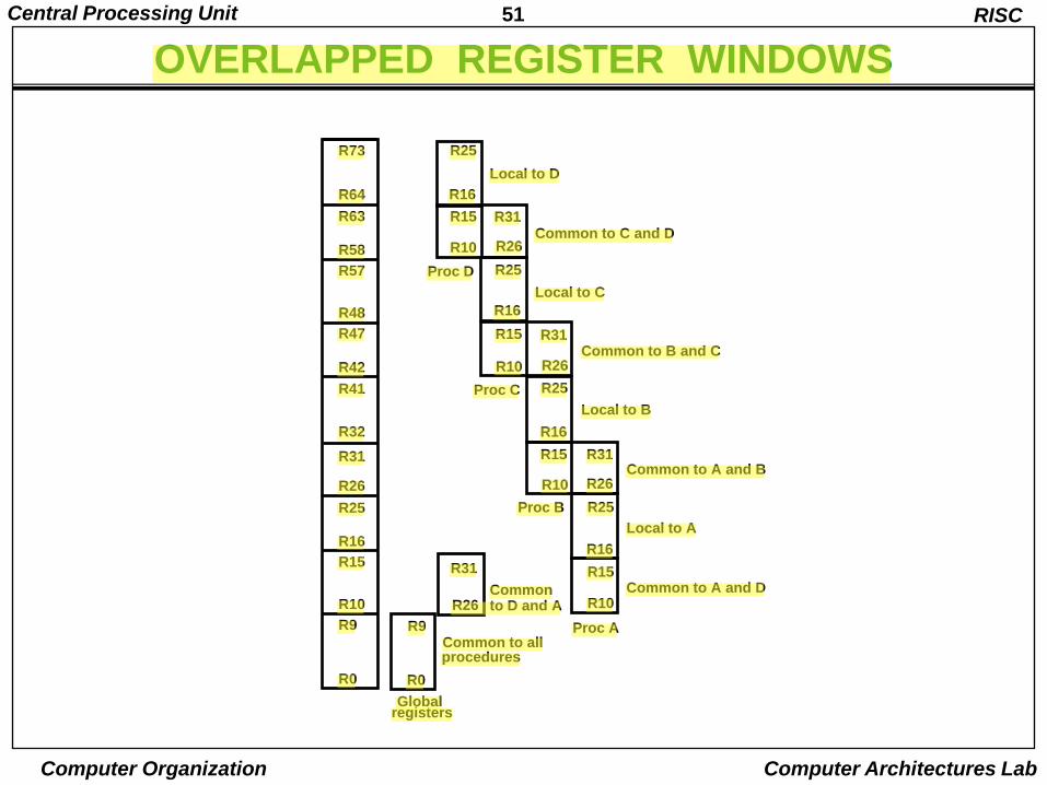
• There are three classes of registers:
– Global Registers
» Available to all functions
– Window local registers
» Variables local to the function
– Window shared registers
» Permit data to be shared without actually needing to copy it
• Only one register window is active at a time
– The active register window is indicated by a pointer
• When a function is called, a new register window is activated
– This is done by incrementing the pointer
• When a function calls a new function, the high numbered registers of the calling function window are shared with the called function as the low numbered registers in its register window
• This way the caller‟s high and the called function‟s low registers overlap and can be used to pass parameters and results
53Central Processing Unit
Computer Organization Computer Architectures Lab
OVERLAPPED REGISTER WINDOWS
• In addition to the overlapped register windows, the processor has some number of registers, G, that are global registers
– This is, all functions can access the global registers.
• The advantage of overlapped register windows is that the processor does not have to push registers on a stack to save values and to pass parameters when there is a function call
– Conversely, pop the stack on a function return
• This saves – Accesses to memory to access the stack.
– The cost of copying the register contents at all
• And, since function calls and returns are so common, this results in a significant savings relative to a stack-based approach
54Central Processing Unit
Computer Organization Computer Architectures Lab
BERKELEY RISC I
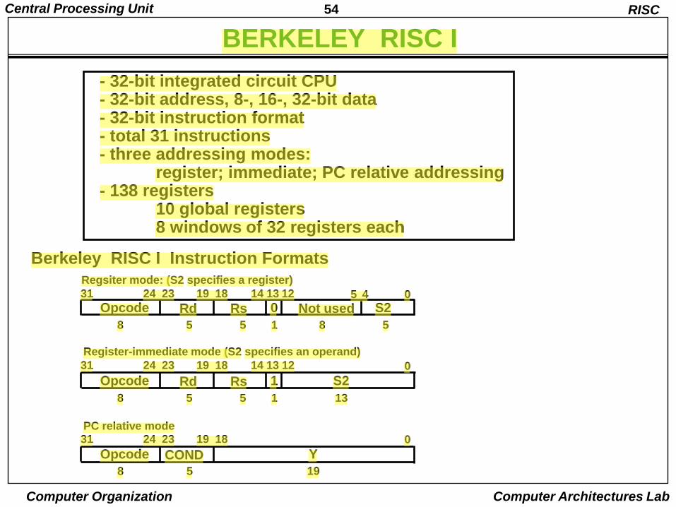
- 32-bit integrated circuit CPU- 32-bit address, 8-, 16-, 32-bit data- 32-bit instruction format- total 31 instructions- three addressing modes:
register; immediate; PC relative addressing- 138 registers
10 global registers 8 windows of 32 registers each
Berkeley RISC I Instruction Formats
RISC
Opcode RsRd 0 Not used S231 24 23 19 18 14 13 12 5 4 0
8 5 5 1 8 5
Opcode RsRd 1 S2
31 24 23 19 18 14 13 12 0
8 5 5 1 13
Opcode COND Y
31 24 23 19 18 0
8 5 19
Regsiter mode: (S2 specifies a register)
Register-immediate mode (S2 specifies an operand)
PC relative mode
55Central Processing Unit
Computer Organization Computer Architectures Lab
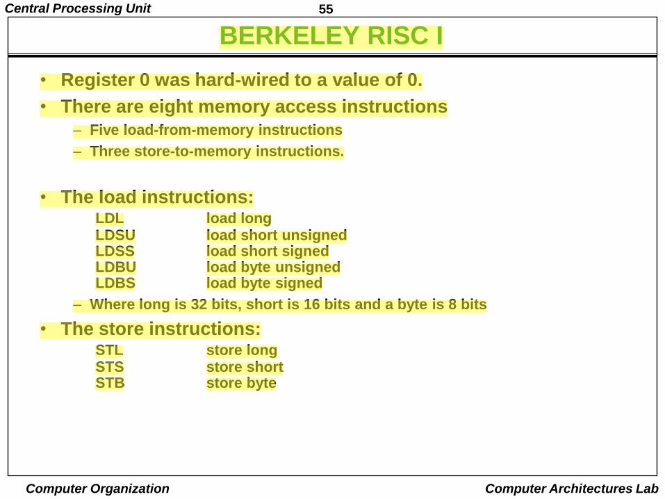
BERKELEY RISC I
• Register 0 was hard-wired to a value of 0.
• There are eight memory access instructions
– Five load-from-memory instructions
– Three store-to-memory instructions.
• The load instructions:LDL load longLDSU load short unsignedLDSS load short signedLDBU load byte unsignedLDBS load byte signed
– Where long is 32 bits, short is 16 bits and a byte is 8 bits
• The store instructions:STL store longSTS store shortSTB store byte
56Central Processing Unit
Computer Organization Computer Architectures Lab
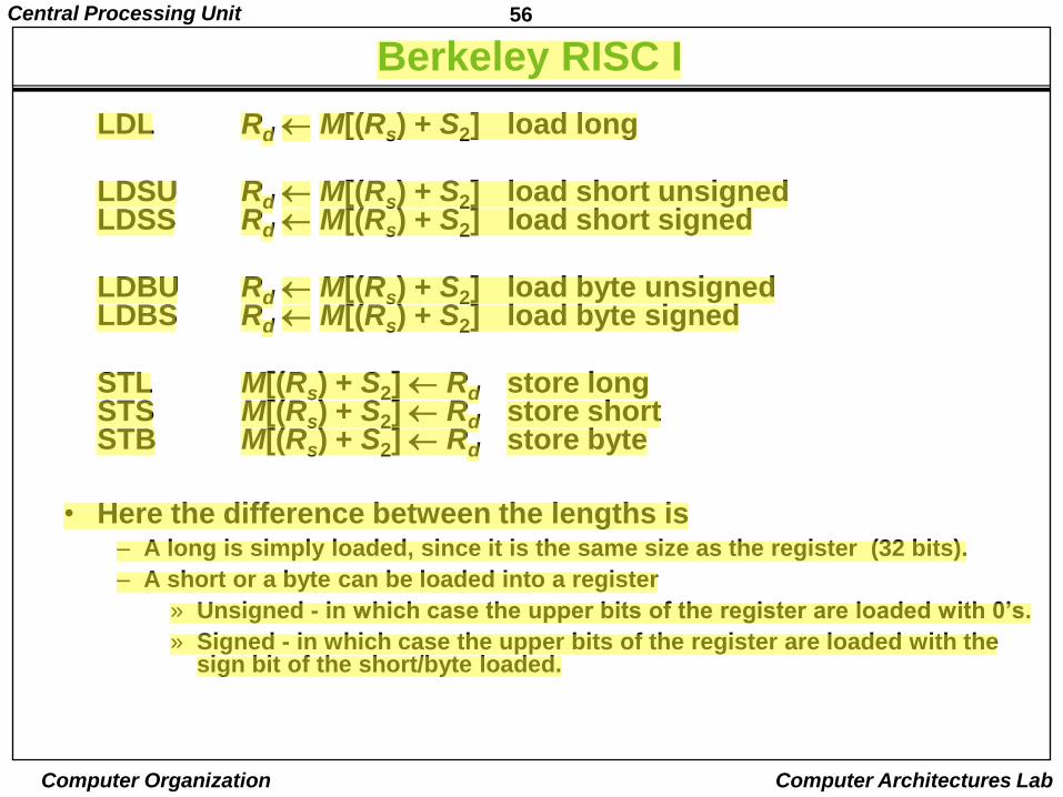
Berkeley RISC I
LDL Rd M[(Rs) + S2] load long
LDSU Rd M[(Rs) + S2] load short unsignedLDSS Rd M[(Rs) + S2] load short signed
LDBU Rd M[(Rs) + S2] load byte unsignedLDBS Rd M[(Rs) + S2] load byte signed
STL M[(Rs) + S2] Rd store longSTS M[(Rs) + S2] Rd store shortSTB M[(Rs) + S2] Rd store byte
• Here the difference between the lengths is – A long is simply loaded, since it is the same size as the register (32 bits).
– A short or a byte can be loaded into a register
» Unsigned - in which case the upper bits of the register are loaded with 0‟s.
» Signed - in which case the upper bits of the register are loaded with the sign bit of the short/byte loaded.

57Central Processing Unit
Computer Organization Computer Architectures Lab
INSTRUCTION SET OF BERKELEY RISC I
Data manipulation instructions
ADD Rs,S2,Rd Rd Rs + S2 Integer add
ADDC Rs,S2,Rd Rd Rs + S2 + carry Add with carry
SUB Rs,S2,Rd Rd Rs - S2 Integer subtract
SUBC Rs,S2,Rd Rd Rs - S2 - carry Subtract with carry
SUBR Rs,S2,Rd Rd S2 - Rs Subtract reverse
SUBCR Rs,S2,Rd Rd S2 - Rs - carry Subtract with carry
AND Rs,S2,Rd Rd Rs S2 AND
OR Rs,S2,Rd Rd Rs S2 OR
XOR Rs,S2,Rd Rd Rs S2 Exclusive-OR
SLL Rs,S2,Rd Rd Rs shifted by S2 Shift-left
SRL Rs,S2,Rd Rd Rs shifted by S2 Shift-right logical
SRA Rs,S2,Rd Rd Rs shifted by S2 Shift-right arithmetic
Data transfer instructions
LDL (Rs)S2,Rd Rd M[Rs + S2] Load long
LDSU (Rs)S2,Rd Rd M[Rs + S2] Load short unsigned
LDSS (Rs)S2,Rd Rd M[Rs + S2] Load short signed
LDBU (Rs)S2,Rd Rd M[Rs + S2] Load byte unsigned
LDBS (Rs)S2,Rd Rd M[Rs + S2] Load byte signed
LDHI Rd,Y Rd Y Load immediate high
STL Rd,(Rs)S2 M[Rs + S2] Rd Store long
STS Rd,(Rs)S2 M[Rs + S2] Rd Store short
STB Rd,(Rs)S2 M[Rs + S2] Rd Store byte
GETPSW Rd Rd PSW Load status word
PUTPSW Rd PSW Rd Set status word
Opcode Operands Register Transfer Description
RISC
58Central Processing Unit
Computer Organization Computer Architectures Lab
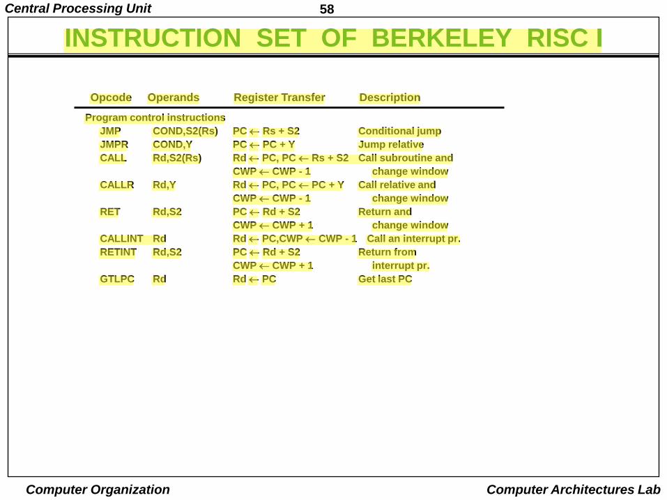
Program control instructions
JMP COND,S2(Rs) PC Rs + S2 Conditional jump
JMPR COND,Y PC PC + Y Jump relative
CALL Rd,S2(Rs) Rd PC, PC Rs + S2 Call subroutine and
CWP CWP - 1 change window
CALLR Rd,Y Rd PC, PC PC + Y Call relative and
CWP CWP - 1 change window
RET Rd,S2 PC Rd + S2 Return and
CWP CWP + 1 change window
CALLINT Rd Rd PC,CWP CWP - 1 Call an interrupt pr.
RETINT Rd,S2 PC Rd + S2 Return from
CWP CWP + 1 interrupt pr.
GTLPC Rd Rd PC Get last PC
Opcode Operands Register Transfer Description
INSTRUCTION SET OF BERKELEY RISC I
59Central Processing Unit
Computer Organization Computer Architectures Lab
CHARACTERISTICS OF RISC
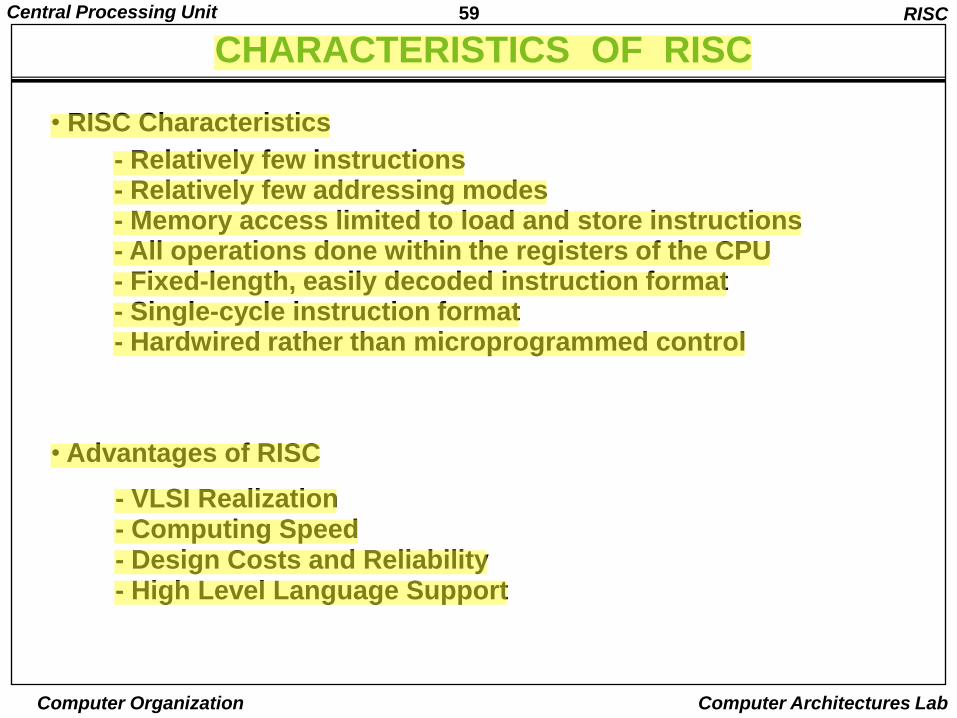
• RISC Characteristics
• Advantages of RISC
- VLSI Realization- Computing Speed- Design Costs and Reliability- High Level Language Support
RISC
- Relatively few instructions- Relatively few addressing modes- Memory access limited to load and store instructions- All operations done within the registers of the CPU- Fixed-length, easily decoded instruction format- Single-cycle instruction format- Hardwired rather than microprogrammed control
60Central Processing Unit
Computer Organization Computer Architectures Lab
ADVANTAGES OF RISC
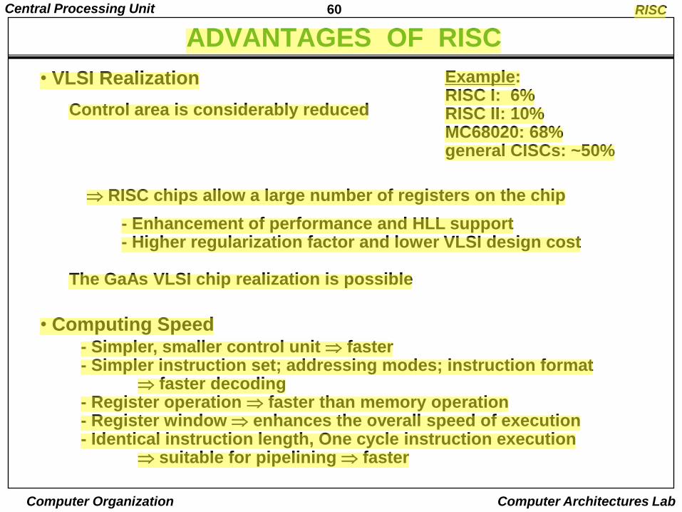
• Computing Speed- Simpler, smaller control unit faster- Simpler instruction set; addressing modes; instruction format
faster decoding- Register operation faster than memory operation- Register window enhances the overall speed of execution- Identical instruction length, One cycle instruction execution
suitable for pipelining faster
RISC
• VLSI Realization
Control area is considerably reduced
Example:RISC I: 6%RISC II: 10%MC68020: 68%general CISCs: ~50%
RISC chips allow a large number of registers on the chip
- Enhancement of performance and HLL support- Higher regularization factor and lower VLSI design cost
The GaAs VLSI chip realization is possible

61Central Processing Unit
Computer Organization Computer Architectures Lab
ADVANTAGES OF RISC
• Design Costs and Reliability
- Shorter time to design reduction in the overall design cost and
reduces the problem that the end product will be obsolete by the time the design is completed
- Simpler, smaller control unit higher reliability
- Simple instruction format (of fixed length) ease of virtual memory management
• High Level Language Support
- A single choice of instruction shorter, simpler compiler
- A large number of CPU registers more efficient code
- Register window Direct support of HLL
- Reduced burden on compiler writer
RISC