Embed Size (px)
Citation preview

CENTRALINE NX PANELBUS DRIVER User Guide
Copyright © 2018 Honeywell GmbH - All Rights Reserved EN2Z-1043GE51 R0218

CENTRALINE NX - PANELBUS DRIVER USER GUIDE
EN2Z-1043GE51 R0218
USER GUIDE CENTRALINE NX – PANELBUS DRIVER
EN2Z-1021GE51 R0418
CENTRALINE NX PANELBUS DRIVER
4.4.xx
USER GUIDE Software License Advisory This document supports software that is proprietary to Honeywell GmbH, Honeywell
Control Systems Ltd. and/or to third party software vendors. Before software delivery, the end user must execute a software license agreement that governs software use. Software license agreement provisions include limiting use of the software to equipment furnished, limiting copying, preserving confidentiality, and prohibiting transfer to a third party. Disclosure, use, or reproduction beyond that permitted in the license agreement is prohibited.
Trademark Information CentraLine and 'close to you' are trademarks of Honeywell Inc. BACnet and ASHRAE are registered trademarks of American Society of Heating,
Refrigerating and Air-Conditioning Engineers. Microsoft and Windows are registered trademarks, and Windows Internet Explorer are trademarks of Microsoft Corporation. Java and other Java-based names are trademarks of Sun Microsystems Inc. and refer to Sun's family of Java-branded technologies. Mozilla and Firefox are trademarks of the Mozilla Foundation. Echelon, LON, LonMark, LonTalk, and LonWorks are registered trademarks of Echelon Corporation.
Tridium, JACE, Niagara Framework, NiagaraAX Framework, Sedona Framework
and Vykon are registered trademarks, and Workbench, WorkPlaceAX, and AXSupervisor, are trademarks of Tridium Inc. All other product names and services mentioned in this publication that is known to be trademarks, registered trademarks, or service marks are the property of their respective owners.

CENTRALINE NX - PANELBUS DRIVER USER GUIDE
EN2Z-1043GE51 R0218

USER GUIDE CENTRALINE NX - PANELBUS DRIVER
EN2Z-1043GE51 R0218
CENTRALINE NX - PANELBUS DRIVER USER GUIDE
EN2Z-1043GE51 R0218 6
CONTENTS
SYSTEM REQUIREMENTS ........................................................................................................................... 7
INSTALLATION ........................................................................................................................... 7 Alternate Usage of Different ARENA NX / COACH NX Versions on Same PC .. 7
CREATE PANELBUS NETWORK ........................................................................................................................... 7
DISCOVER PANELBUS MODULES AND ADD THEM TO STATION ................................................................................... 11 View / Modify Panelbus Module Properties ........................................................ 14
VIEW / MODIFY POINT PROPERTIES OF MODULE ............................................................................................................ 16 AI and AO Point Configuration Parameter Descriptions ..................................... 22 Further Procedures ............................................................................................ 25
Setting Datapoint into Manual Mode (Manual Override) ................................ 25 Setting Datapoint from Override Mode into Auto Mode ................................. 25
CONFIGURATION AND USE OF ENHANCED DATAPOINT CREATION MODULE ............................................................ 27 I/O Creation Configuration.................................................................................. 27 Create Datapoint via Context Menu ................................................................... 27 Drag&Drop Datapoint from Palette or Nav Tree ................................................. 30 Copy Datapoints ................................................................................................. 32
ALARM HANDLING ........................................................................................................................... 36
PANELBUS ANALYZER VIEW ........................................................................................................................... 36
USER GUIDE CENTRALINE NX - PANELBUS DRIVER
7 EN2Z-1043GE51 R0218
SYSTEM REQUIREMENTS
Niagara Niagara 4.4.xx and higher. Products and OS Numbers The Panelbus Driver will be working with CentraLine Products only.
For detailed information on the applicable controllers including their OS Numbers and licenses, please download the corresponding, product data, software release bulletin and/or the compatibility matrix at:
Product Data http://products.centraline.com/en/
Software Release Bulletin https://www.centraline.com/partnerweb/index.php?id=847&route=article%2Findex&directory_id=47&direct_link=1 Compatibility Matrix https://clfaq.ge51.honeywell.de/?action=artikel&cat=70&id=1616&artlang=en
Licenses and Point Handling When having a license allowing only a limited number of points and you are deleting
points, the free number points are not available instantly. To make the free number of points available again, please restart the station.
When having a license allowing only a limited number of points and you are deleting
points, the free number points are not available instantly. To make the free number of points available again, please restart the station.
INSTALLATION
The Panelbus driver will be installed with the NX setup by default.
Alternate Usage of Different ARENA NX / COACH NX Versions on Same PC
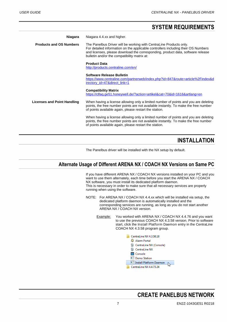
If you have different ARENA NX / COACH NX versions installed on your PC and you want to use them alternately, each time before you start the ARENA NX / COACH NX software, you must install its dedicated platform daemon. This is necessary in order to make sure that all necessary services are properly running when using the software. NOTE: For ARENA NX / COACH NX 4.4.xx which will be installed via setup, the
dedicated platform daemon is automatically installed and the corresponding services are running, as long as you do not start another ARENA NX / COACH NX version.
Example: You worked with ARENA NX / COACH NX 4.4.76 and you want
to use the previous COACH NX 4.3.58 version. Prior to software start, click the Install Platform Daemon entry in the CentraLine
COACH NX 4.3.58 program group.
CREATE PANELBUS NETWORK
CENTRALINE NX - PANELBUS DRIVER USER GUIDE
EN2Z-1043GE51 R0218 8
The following procedure describes the Panelbus network startup on a commissioned EAGLEHAWK controller. The Panelbus can also be configured in offline mode but in this case, the Panelbus network will stay in ´fault` state. As a result, no Panelbus modules can be discovered and only the EAGLEHAWK controller communicates with the Panelbus modules. It’s recommended to create a new station using COACH NX in offline mode. The Panelbus network should then be added to the ´offline` station which is running on the PC. Then the station should be copied to the EAGLEHAWK controller using the Commissioning Wizard. When following this procedure the necessary Panelbus files are copied automatically to the EAGLEHAWK controller.
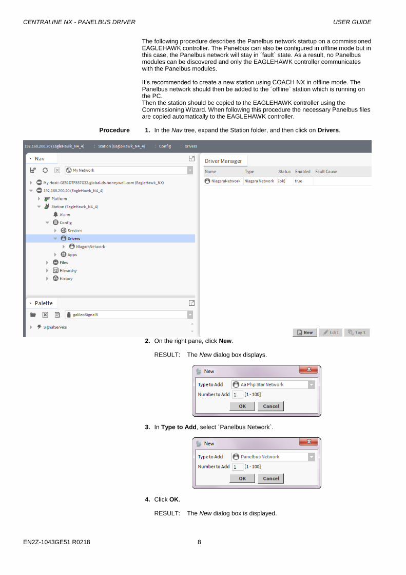
Procedure 1. In the Nav tree, expand the Station folder, and then click on Drivers.
2. On the right pane, click New.
RESULT: The New dialog box displays.
3. In Type to Add, select ´Panelbus Network`.
4. Click OK.
RESULT: The New dialog box is displayed.
USER GUIDE CENTRALINE NX - PANELBUS DRIVER
9 EN2Z-1043GE51 R0218
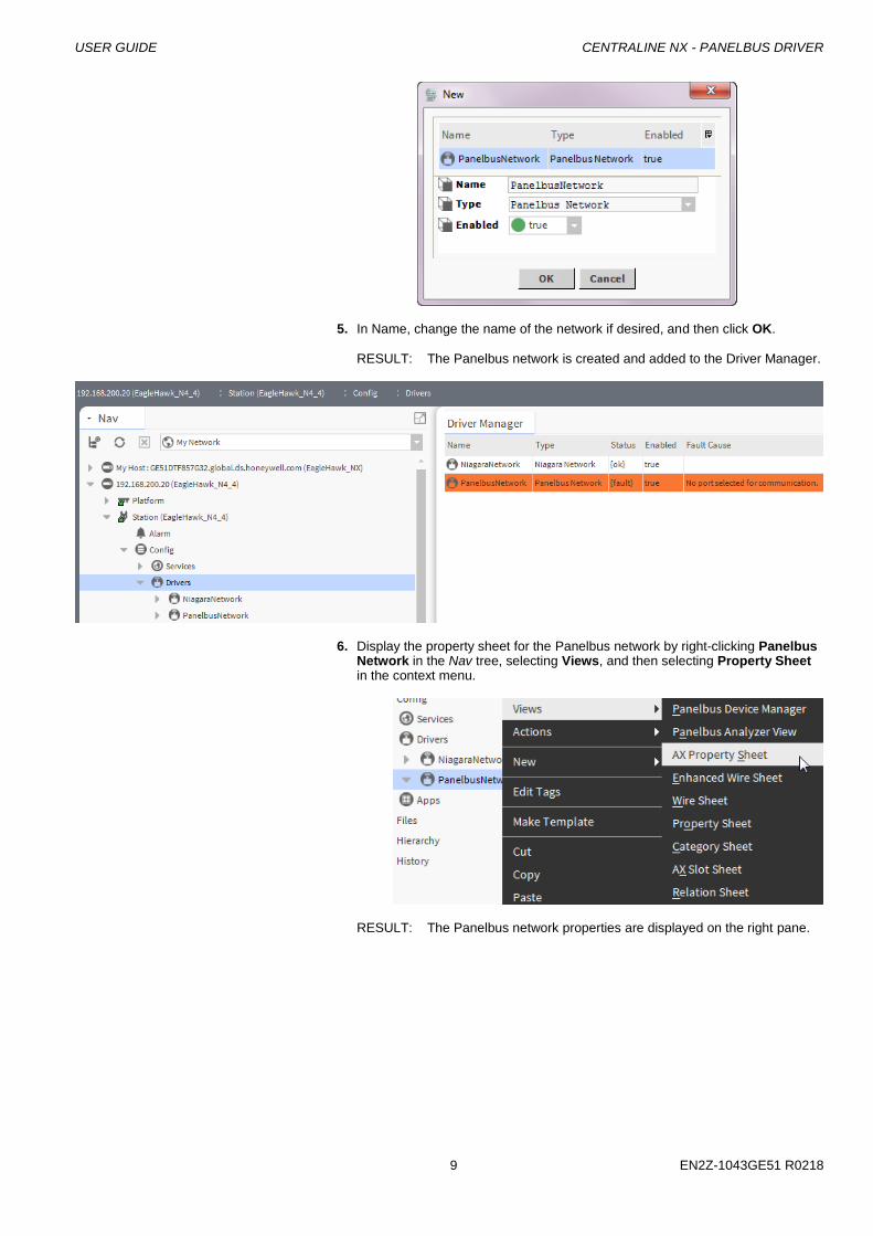
5. In Name, change the name of the network if desired, and then click OK.
RESULT: The Panelbus network is created and added to the Driver Manager.
6. Display the property sheet for the Panelbus network by right-clicking Panelbus Network in the Nav tree, selecting Views, and then selecting Property Sheet in the context menu.
RESULT: The Panelbus network properties are displayed on the right pane.

CENTRALINE NX - PANELBUS DRIVER USER GUIDE
EN2Z-1043GE51 R0218 10
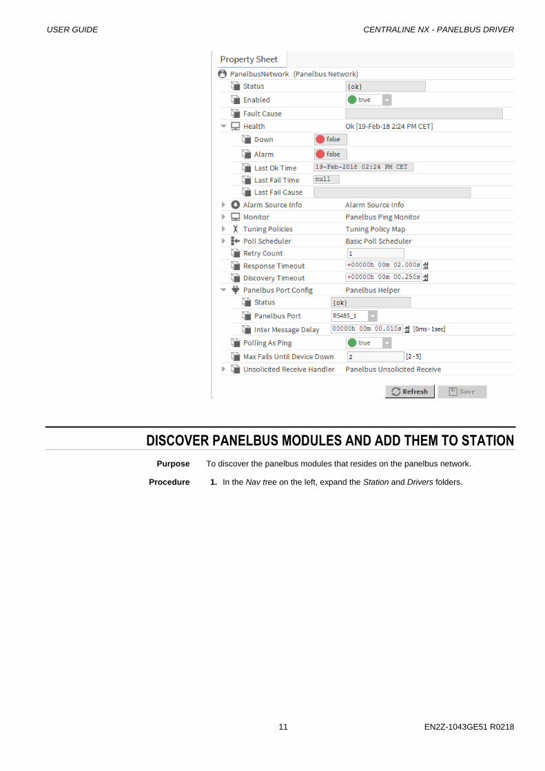
7. Under Panelbus Port Config, select the port (RS485_1 or RS485_2) from the
Panelbus Port drop-down listbox.
NOTE: This handling is different to all other RS485-based drivers within COACH NX. In this case, the Panelbus Ports match the labeling on the EAGLEHAWK.
8. Click Save button.
RESULT: The Panelbus network properties are updated. The Status fields
show ´ok` indicating that the network is properly working.
USER GUIDE CENTRALINE NX - PANELBUS DRIVER
11 EN2Z-1043GE51 R0218
DISCOVER PANELBUS MODULES AND ADD THEM TO STATION
Purpose To discover the panelbus modules that resides on the panelbus network.
Procedure 1. In the Nav tree on the left, expand the Station and Drivers folders.
CENTRALINE NX - PANELBUS DRIVER USER GUIDE
EN2Z-1043GE51 R0218 12
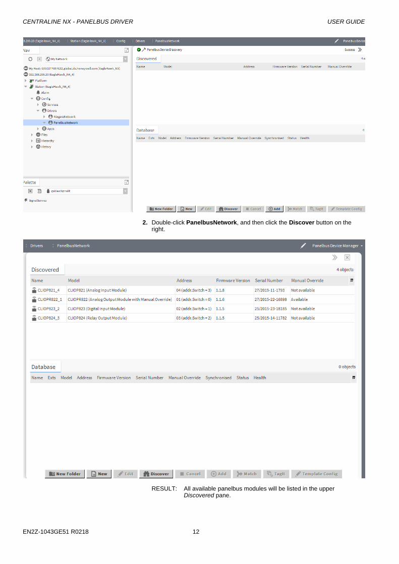
2. Double-click PanelbusNetwork, and then click the Discover button on the right.
RESULT: All available panelbus modules will be listed in the upper Discovered pane.
USER GUIDE CENTRALINE NX - PANELBUS DRIVER
13 EN2Z-1043GE51 R0218
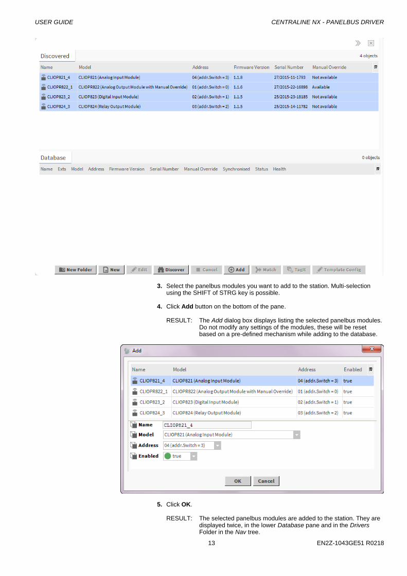
3. Select the panelbus modules you want to add to the station. Multi-selection using the SHIFT of STRG key is possible.
4. Click Add button on the bottom of the pane.
RESULT: The Add dialog box displays listing the selected panelbus modules.
Do not modify any settings of the modules, these will be reset based on a pre-defined mechanism while adding to the database.
5. Click OK.
RESULT: The selected panelbus modules are added to the station. They are displayed twice, in the lower Database pane and in the Drivers Folder in the Nav tree.
CENTRALINE NX - PANELBUS DRIVER USER GUIDE
EN2Z-1043GE51 R0218 14
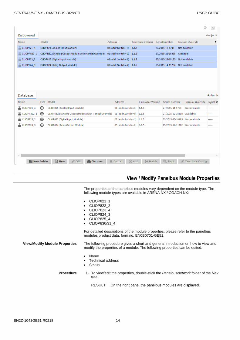
View / Modify Panelbus Module Properties
The properties of the panelbus modules vary dependent on the module type. The following module types are available in ARENA NX / COACH NX:
CLIOP821_1
CLIOP822_2
CLIOP823_4
CLIOP824_3
CLIOP825_4
CLIOP830/31_4 For detailed descriptions of the module properties, please refer to the panelbus modules product data, form no. EN0B0701-GE51.
View/Modify Module Properties The following procedure gives a short and general introduction on how to view and
modify the properties of a module. The following properties can be edited:
Name
Technical address
Status Procedure 1. To view/edit the properties, double-click the PanelbusNetwork folder of the Nav
tree. RESULT: On the right pane, the panelbus modules are displayed.
USER GUIDE CENTRALINE NX - PANELBUS DRIVER
15 EN2Z-1043GE51 R0218
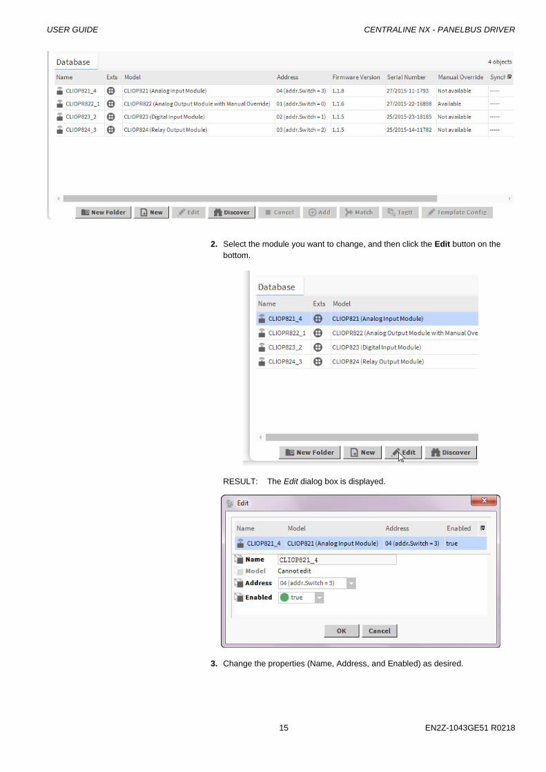
2. Select the module you want to change, and then click the Edit button on the
bottom.
RESULT: The Edit dialog box is displayed.
3. Change the properties (Name, Address, and Enabled) as desired.
CENTRALINE NX - PANELBUS DRIVER USER GUIDE
EN2Z-1043GE51 R0218 16
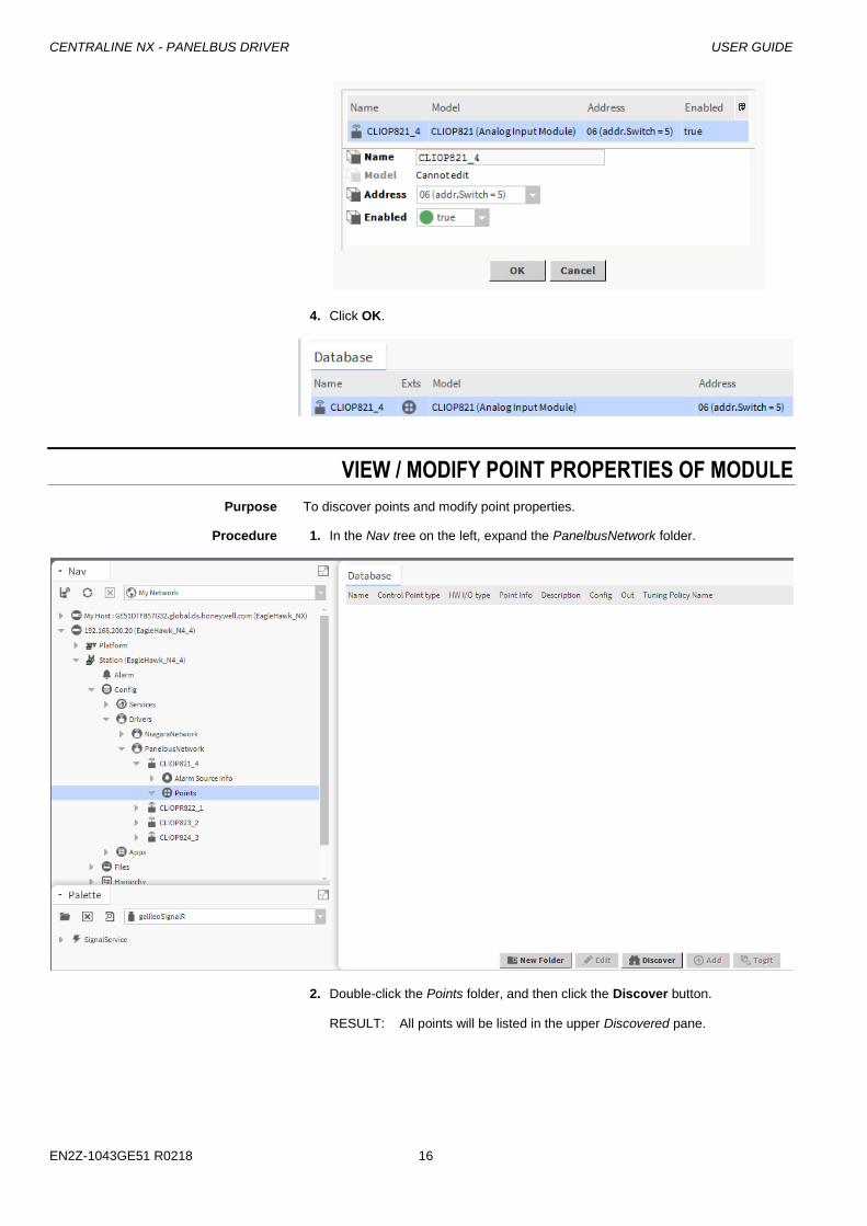
4. Click OK.
VIEW / MODIFY POINT PROPERTIES OF MODULE
Purpose To discover points and modify point properties.
Procedure 1. In the Nav tree on the left, expand the PanelbusNetwork folder.
2. Double-click the Points folder, and then click the Discover button.
RESULT: All points will be listed in the upper Discovered pane.
USER GUIDE CENTRALINE NX - PANELBUS DRIVER
17 EN2Z-1043GE51 R0218
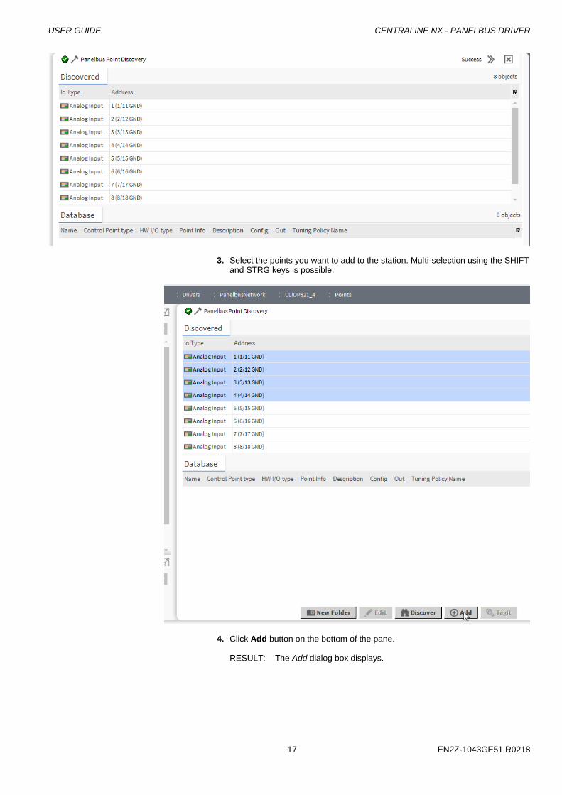
3. Select the points you want to add to the station. Multi-selection using the SHIFT and STRG keys is possible.
4. Click Add button on the bottom of the pane.
RESULT: The Add dialog box displays.

CENTRALINE NX - PANELBUS DRIVER USER GUIDE
EN2Z-1043GE51 R0218 18
5. In this dialog, you can modify point properties before adding the points to the database. You can apply these changes to one or multiple points. White colored fields are enabled and can be modified. Beige colored fields are display only. NOTE: When changing the Control Point Type property of the point, its
corresponding Config settings displayed below are updated accordingly. The control point type property cannot be reverted after the point has been added to database.
All other properties can be changed after the addition using the Edit function (see the following steps)
USER GUIDE CENTRALINE NX - PANELBUS DRIVER
19 EN2Z-1043GE51 R0218
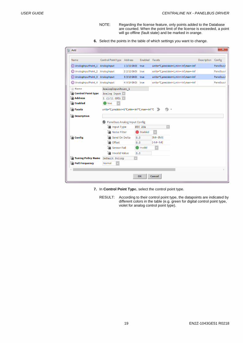
NOTE: Regarding the license feature, only points added to the Database are counted. When the point limit of the license is exceeded, a point will go offline (fault state) and be marked in orange.
6. Select the points in the table of which settings you want to change.
7. In Control Point Type, select the control point type.
RESULT: According to their control point type, the datapoints are indicated by different colors in the table (e.g. green for digital control point type, violet for analog control point type).
CENTRALINE NX - PANELBUS DRIVER USER GUIDE
EN2Z-1043GE51 R0218 20
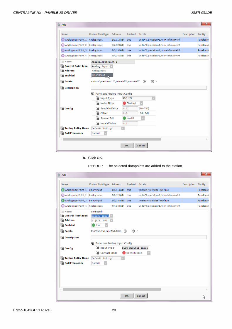
8. Click OK.
RESULT: The selected datapoints are added to the station.
USER GUIDE CENTRALINE NX - PANELBUS DRIVER
21 EN2Z-1043GE51 R0218
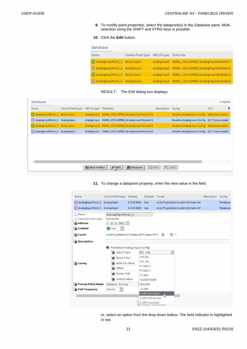
9. To modify point properties, select the datapoint(s) in the Database pane. Multi-selection using the SHIFT and STRG keys is possible.
10. Click the Edit button.
RESULT: The Edit dialog box displays.
11. To change a datapoint property, enter the new value in the field.
or, select an option from the drop-down listbox. The field indicator is highlighted
in red.
CENTRALINE NX - PANELBUS DRIVER USER GUIDE
EN2Z-1043GE51 R0218 22
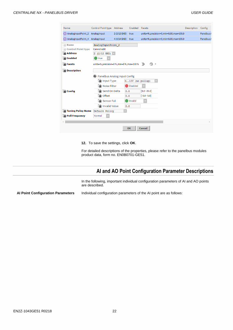
12. To save the settings, click OK.
For detailed descriptions of the properties, please refer to the panelbus modules product data, form no. EN0B0701-GE51.
AI and AO Point Configuration Parameter Descriptions
In the following, important individual configuration parameters of AI and AO points are described.
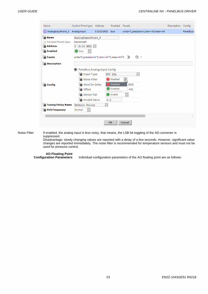
AI Point Configuration Parameters Individual configuration parameters of the AI point are as follows:
USER GUIDE CENTRALINE NX - PANELBUS DRIVER
23 EN2Z-1043GE51 R0218
Noise Filter If enabled, the analog input is less noisy, that means, the LSB bit toggling of the AD-converter is suppressed.
Disadvantage: slowly changing values are reported with a delay of a few seconds. However, significant value changes are reported immediately. The noise filter is recommended for temperature sensors and must not be used for pressure control.
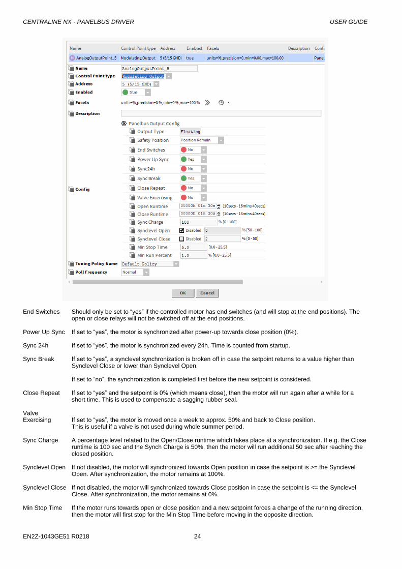
AO Floating Point Configuration Parameters Individual configuration parameters of the AO floating point are as follows:
CENTRALINE NX - PANELBUS DRIVER USER GUIDE
EN2Z-1043GE51 R0218 24
End Switches Should only be set to “yes” if the controlled motor has end switches (and will stop at the end positions). The
open or close relays will not be switched off at the end positions. Power Up Sync If set to “yes”, the motor is synchronized after power-up towards close position (0%). Sync 24h If set to “yes”, the motor is synchronized every 24h. Time is counted from startup. Sync Break If set to “yes”, a synclevel synchronization is broken off in case the setpoint returns to a value higher than
Synclevel Close or lower than Synclevel Open. If set to “no”, the synchronization is completed first before the new setpoint is considered.
Close Repeat If set to “yes” and the setpoint is 0% (which means close), then the motor will run again after a while for a
short time. This is used to compensate a sagging rubber seal. Valve Exercising If set to “yes”, the motor is moved once a week to approx. 50% and back to Close position.
This is useful if a valve is not used during whole summer period. Sync Charge A percentage level related to the Open/Close runtime which takes place at a synchronization. If e.g. the Close
runtime is 100 sec and the Synch Charge is 50%, then the motor will run additional 50 sec after reaching the closed position.
Synclevel Open If not disabled, the motor will synchronized towards Open position in case the setpoint is >= the Synclevel
Open. After synchronization, the motor remains at 100%. Synclevel Close If not disabled, the motor will synchronized towards Close position in case the setpoint is <= the Synclevel
Close. After synchronization, the motor remains at 0%. Min Stop Time If the motor runs towards open or close position and a new setpoint forces a change of the running direction,
then the motor will first stop for the Min Stop Time before moving in the opposite direction.
USER GUIDE CENTRALINE NX - PANELBUS DRIVER
25 EN2Z-1043GE51 R0218
Min Run Time If the setpoint changes only small amounts, then the motor will at least run with the Min Run Time, even setpoint will be overrun by this.
Further Procedures
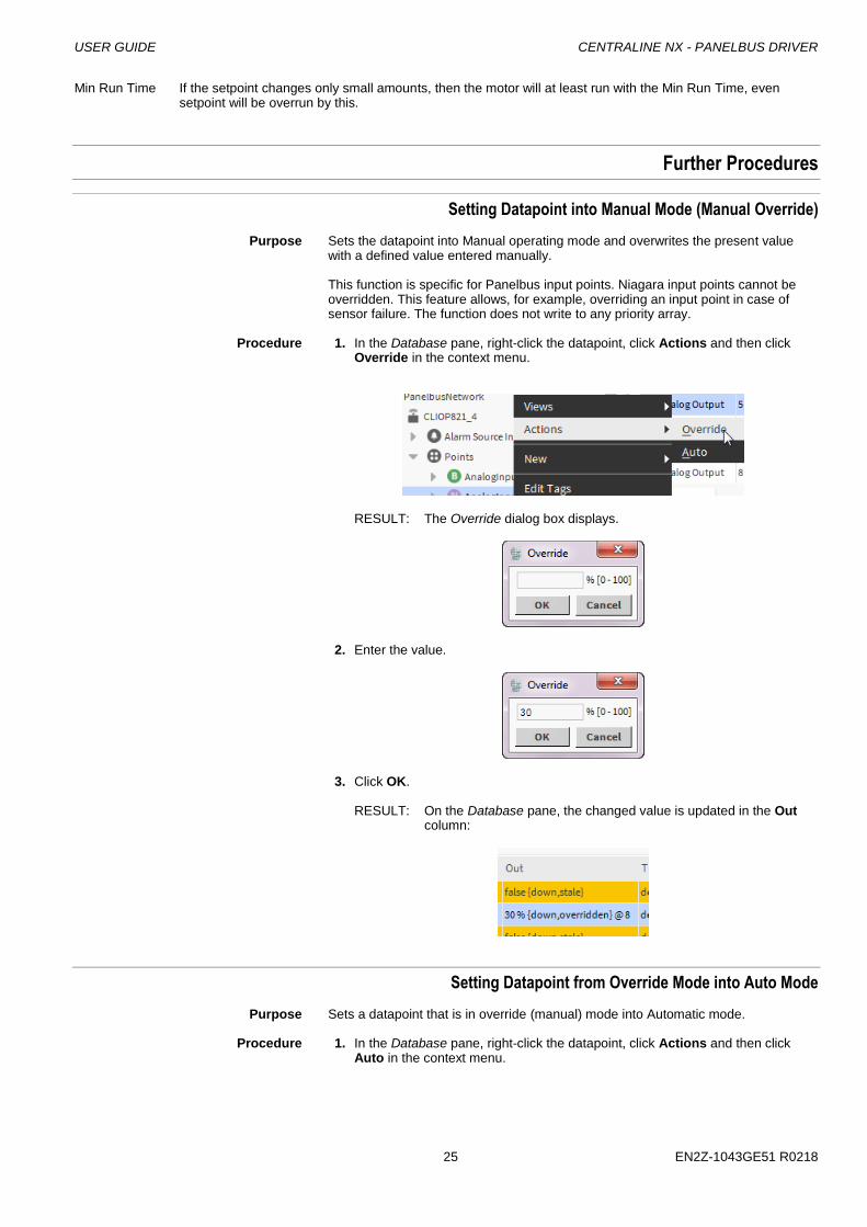
Setting Datapoint into Manual Mode (Manual Override)
Purpose Sets the datapoint into Manual operating mode and overwrites the present value with a defined value entered manually.
This function is specific for Panelbus input points. Niagara input points cannot be overridden. This feature allows, for example, overriding an input point in case of sensor failure. The function does not write to any priority array.
Procedure 1. In the Database pane, right-click the datapoint, click Actions and then click
Override in the context menu.
RESULT: The Override dialog box displays.
2. Enter the value.
3. Click OK.
RESULT: On the Database pane, the changed value is updated in the Out column:
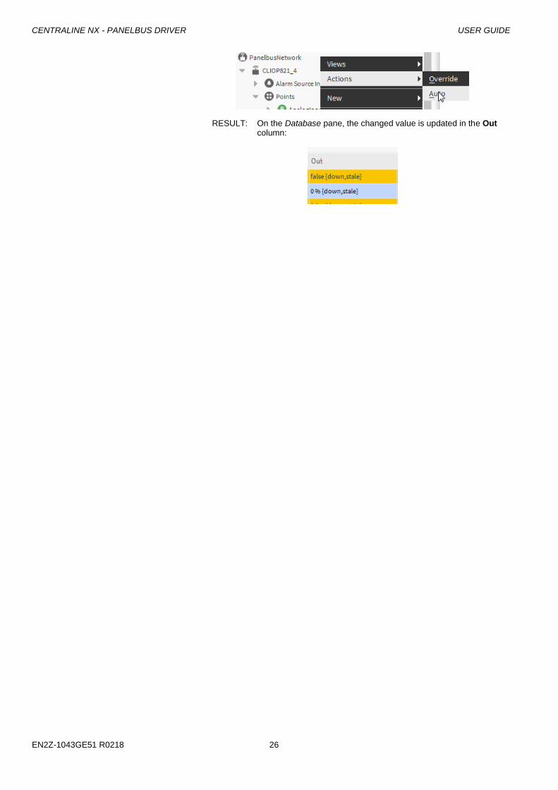
Setting Datapoint from Override Mode into Auto Mode
Purpose Sets a datapoint that is in override (manual) mode into Automatic mode. Procedure 1. In the Database pane, right-click the datapoint, click Actions and then click
Auto in the context menu.
CENTRALINE NX - PANELBUS DRIVER USER GUIDE
EN2Z-1043GE51 R0218 26
RESULT: On the Database pane, the changed value is updated in the Out column:
USER GUIDE CENTRALINE NX - PANELBUS DRIVER
27 EN2Z-1043GE51 R0218
CONFIGURATION AND USE OF ENHANCED DATAPOINT CREATION MODULE
The following sections describe the configuration and use of the enhanced data point creation module. It can be used in offline and online mode. It is recommended to do the engineering using COACH in offline mode. This means that the station is running on the PC. Then in online mode, the station should be copied to the EAGLEHAWK controller using the Commissioning Wizard. When following this procedure, the necessary files are copied automatically to the EAGLEHAWK controller The enhanced data point creation module provides the following functions:
I/O creation configuration
Datapoint creation via context menu in the Nav tree
Datapoint creation via Drag&Drop of datapoints from palette or Nav tree
Copy Datapoints
I/O Creation Configuration
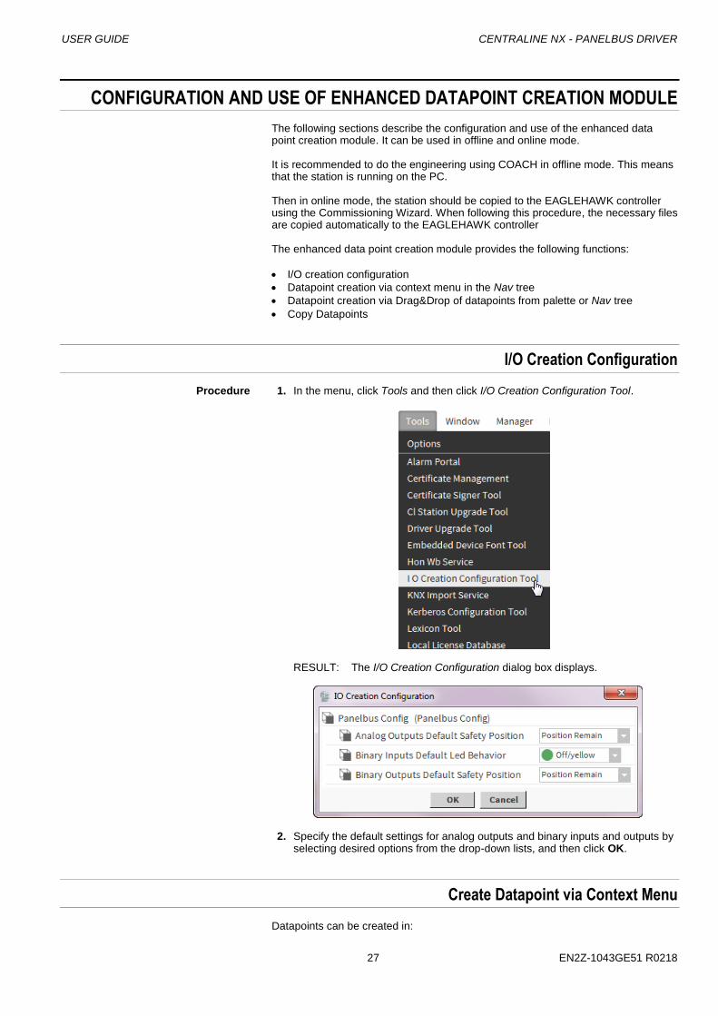
Procedure 1. In the menu, click Tools and then click I/O Creation Configuration Tool.
RESULT: The I/O Creation Configuration dialog box displays.
2. Specify the default settings for analog outputs and binary inputs and outputs by selecting desired options from the drop-down lists, and then click OK.
Create Datapoint via Context Menu
Datapoints can be created in:
CENTRALINE NX - PANELBUS DRIVER USER GUIDE
EN2Z-1043GE51 R0218 28
individual folders
the points folder
points objects
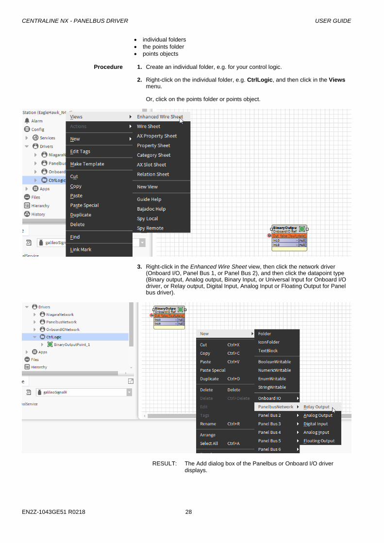
Procedure 1. Create an individual folder, e.g. for your control logic. 2. Right-click on the individual folder, e.g. CtrlLogic, and then click in the Views
menu. Or, click on the points folder or points object.
3. Right-click in the Enhanced Wire Sheet view, then click the network driver (Onboard I/O, Panel Bus 1, or Panel Bus 2), and then click the datapoint type (Binary output, Analog output, Binary Input, or Universal Input for Onboard I/O driver, or Relay output, Digital Input, Analog Input or Floating Output for Panel bus driver).
RESULT: The Add dialog box of the Panelbus or Onboard I/O driver displays.
USER GUIDE CENTRALINE NX - PANELBUS DRIVER
29 EN2Z-1043GE51 R0218
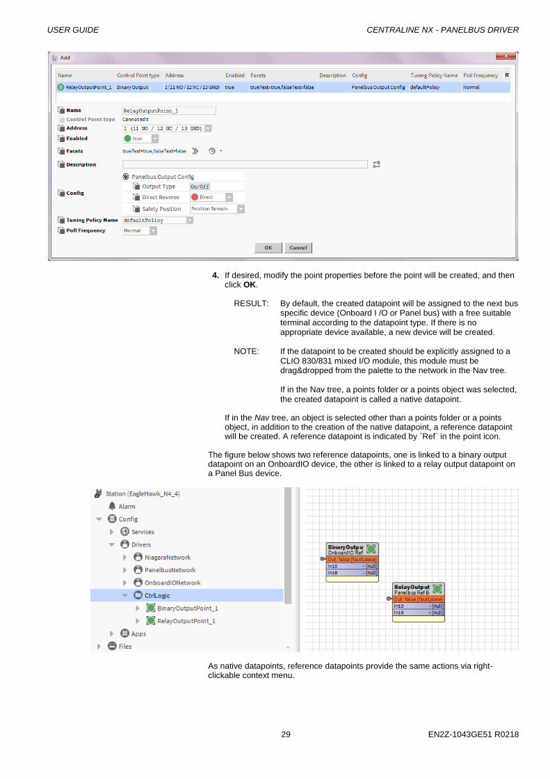
4. If desired, modify the point properties before the point will be created, and then
click OK.
RESULT: By default, the created datapoint will be assigned to the next bus specific device (Onboard I /O or Panel bus) with a free suitable terminal according to the datapoint type. If there is no appropriate device available, a new device will be created.
NOTE: If the datapoint to be created should be explicitly assigned to a
CLIO 830/831 mixed I/O module, this module must be drag&dropped from the palette to the network in the Nav tree.
If in the Nav tree, a points folder or a points object was selected,
the created datapoint is called a native datapoint. If in the Nav tree, an object is selected other than a points folder or a points
object, in addition to the creation of the native datapoint, a reference datapoint will be created. A reference datapoint is indicated by ´Ref` in the point icon.
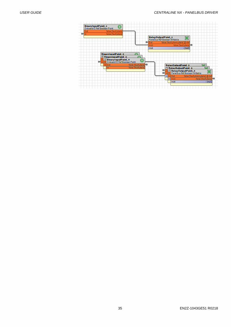
The figure below shows two reference datapoints, one is linked to a binary output datapoint on an OnboardIO device, the other is linked to a relay output datapoint on a Panel Bus device.
As native datapoints, reference datapoints provide the same actions via right-clickable context menu.
CENTRALINE NX - PANELBUS DRIVER USER GUIDE
EN2Z-1043GE51 R0218 30
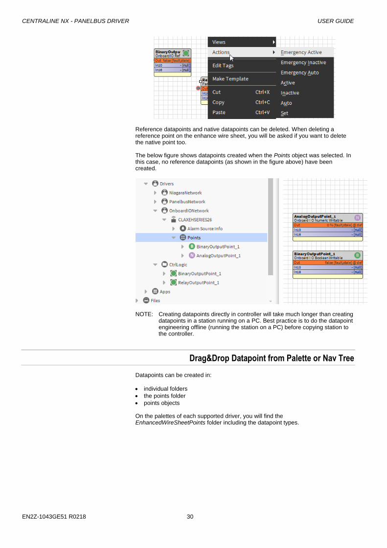
Reference datapoints and native datapoints can be deleted. When deleting a reference point on the enhance wire sheet, you will be asked if you want to delete the native point too. The below figure shows datapoints created when the Points object was selected. In this case, no reference datapoints (as shown in the figure above) have been created.
NOTE: Creating datapoints directly in controller will take much longer than creating datapoints in a station running on a PC. Best practice is to do the datapoint engineering offline (running the station on a PC) before copying station to the controller.
Drag&Drop Datapoint from Palette or Nav Tree
Datapoints can be created in:
individual folders
the points folder
points objects
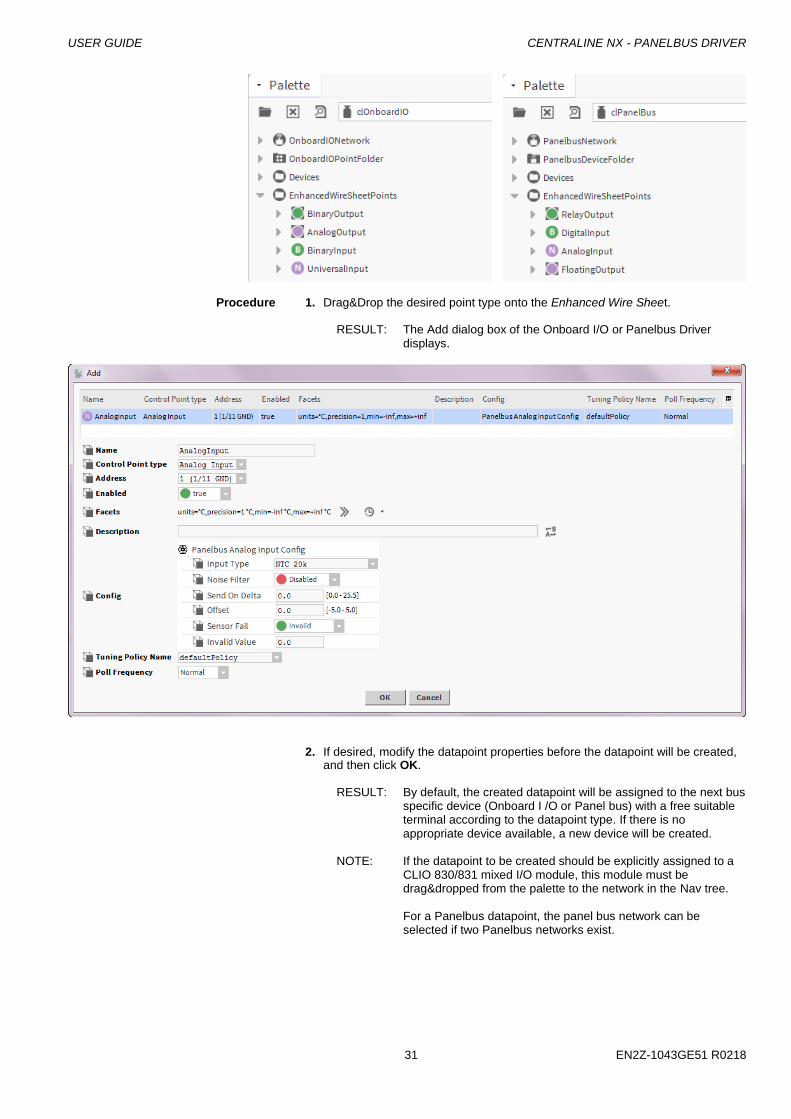
On the palettes of each supported driver, you will find the EnhancedWireSheetPoints folder including the datapoint types.
USER GUIDE CENTRALINE NX - PANELBUS DRIVER
31 EN2Z-1043GE51 R0218
Procedure 1. Drag&Drop the desired point type onto the Enhanced Wire Sheet.
RESULT: The Add dialog box of the Onboard I/O or Panelbus Driver displays.
2. If desired, modify the datapoint properties before the datapoint will be created,
and then click OK.
RESULT: By default, the created datapoint will be assigned to the next bus specific device (Onboard I /O or Panel bus) with a free suitable terminal according to the datapoint type. If there is no appropriate device available, a new device will be created.
NOTE: If the datapoint to be created should be explicitly assigned to a
CLIO 830/831 mixed I/O module, this module must be drag&dropped from the palette to the network in the Nav tree.
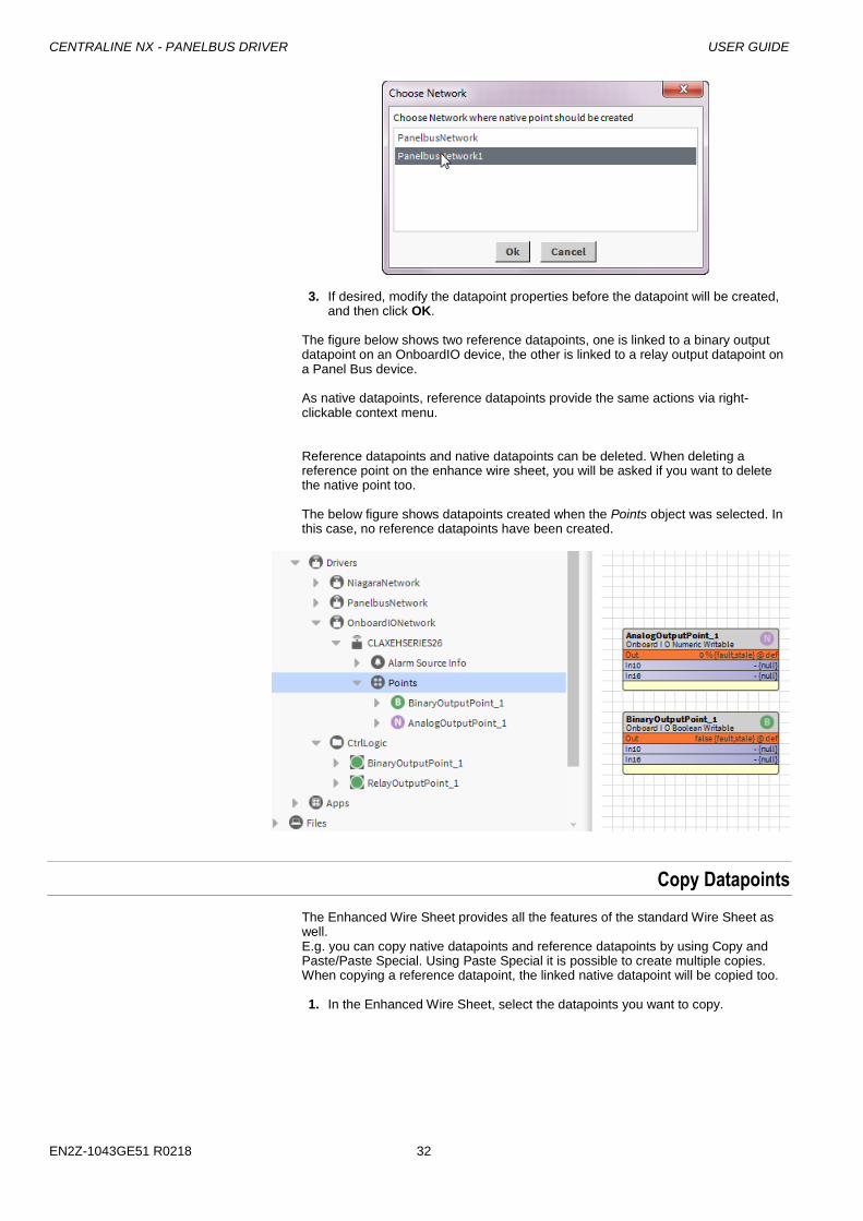
For a Panelbus datapoint, the panel bus network can be
selected if two Panelbus networks exist.
CENTRALINE NX - PANELBUS DRIVER USER GUIDE
EN2Z-1043GE51 R0218 32
3. If desired, modify the datapoint properties before the datapoint will be created,
and then click OK.
The figure below shows two reference datapoints, one is linked to a binary output datapoint on an OnboardIO device, the other is linked to a relay output datapoint on a Panel Bus device. As native datapoints, reference datapoints provide the same actions via right-clickable context menu.
Reference datapoints and native datapoints can be deleted. When deleting a reference point on the enhance wire sheet, you will be asked if you want to delete the native point too. The below figure shows datapoints created when the Points object was selected. In this case, no reference datapoints have been created.
Copy Datapoints
The Enhanced Wire Sheet provides all the features of the standard Wire Sheet as well. E.g. you can copy native datapoints and reference datapoints by using Copy and Paste/Paste Special. Using Paste Special it is possible to create multiple copies. When copying a reference datapoint, the linked native datapoint will be copied too.
1. In the Enhanced Wire Sheet, select the datapoints you want to copy.
USER GUIDE CENTRALINE NX - PANELBUS DRIVER
33 EN2Z-1043GE51 R0218
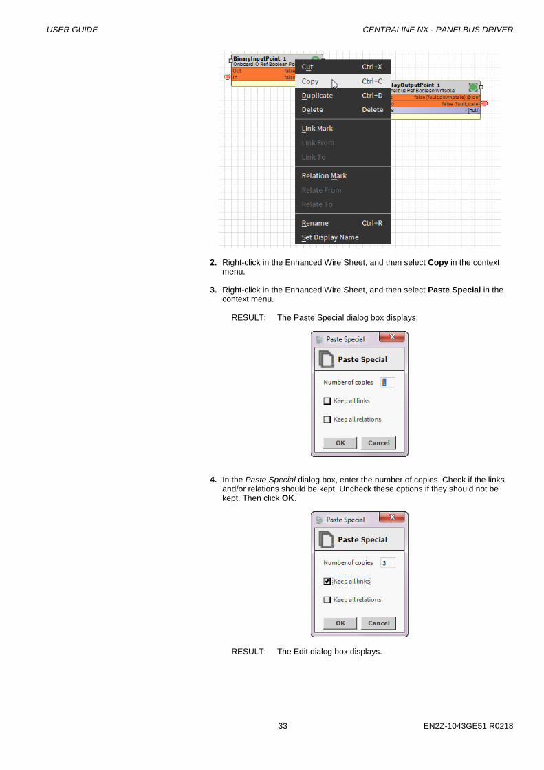
2. Right-click in the Enhanced Wire Sheet, and then select Copy in the context
menu. 3. Right-click in the Enhanced Wire Sheet, and then select Paste Special in the
context menu.
RESULT: The Paste Special dialog box displays.
4. In the Paste Special dialog box, enter the number of copies. Check if the links
and/or relations should be kept. Uncheck these options if they should not be kept. Then click OK.
RESULT: The Edit dialog box displays.
CENTRALINE NX - PANELBUS DRIVER USER GUIDE
EN2Z-1043GE51 R0218 34
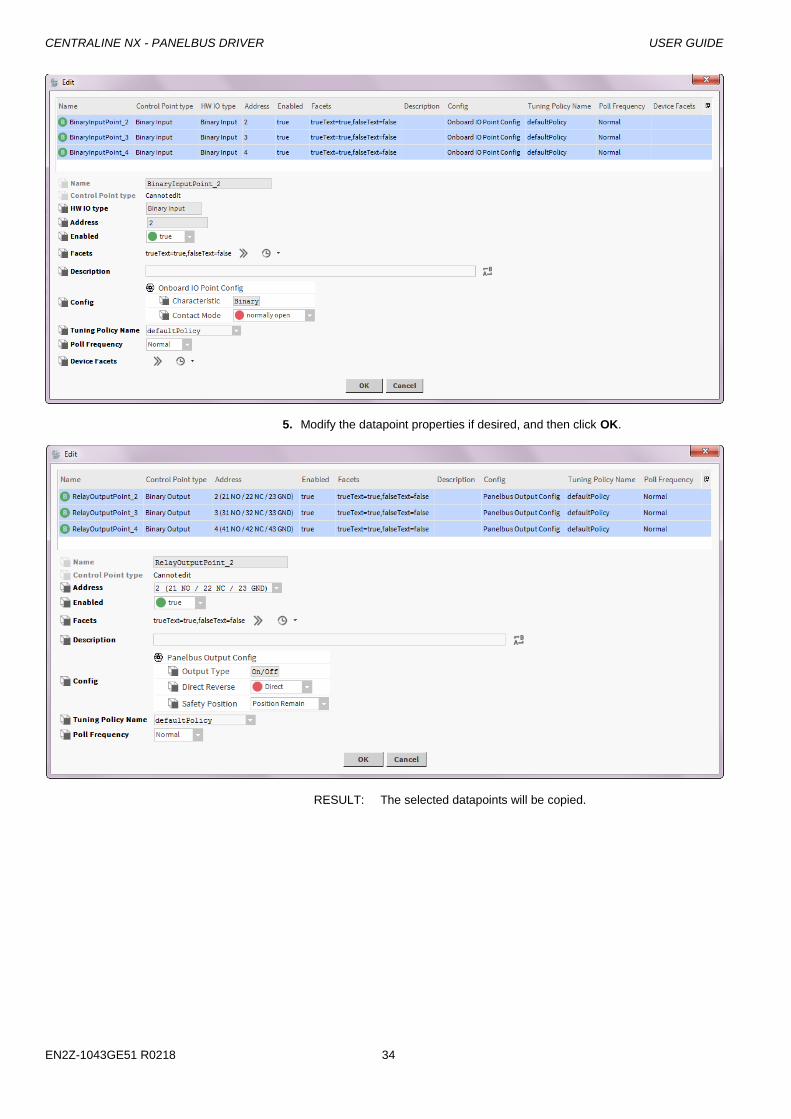
5. Modify the datapoint properties if desired, and then click OK.
RESULT: The selected datapoints will be copied.
USER GUIDE CENTRALINE NX - PANELBUS DRIVER
35 EN2Z-1043GE51 R0218
CENTRALINE NX - PANELBUS DRIVER USER GUIDE
EN2Z-1043GE51 R0218 36
ALARM HANDLING
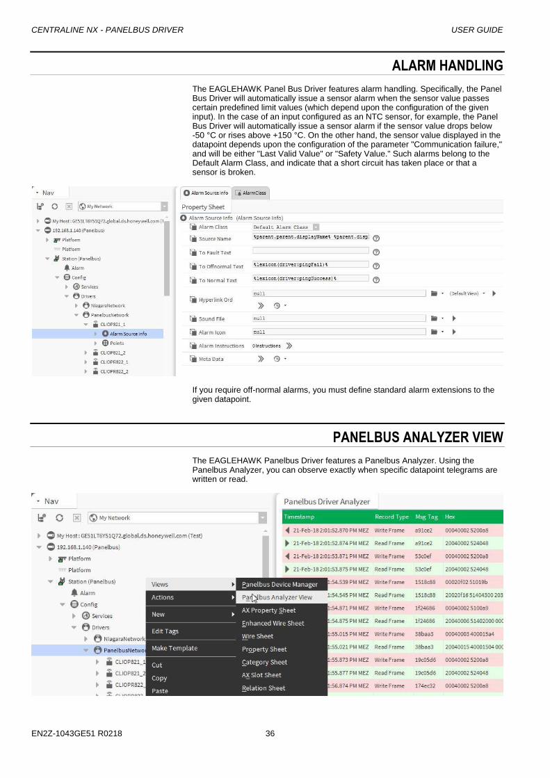
The EAGLEHAWK Panel Bus Driver features alarm handling. Specifically, the Panel Bus Driver will automatically issue a sensor alarm when the sensor value passes certain predefined limit values (which depend upon the configuration of the given input). In the case of an input configured as an NTC sensor, for example, the Panel Bus Driver will automatically issue a sensor alarm if the sensor value drops below -50 °C or rises above +150 °C. On the other hand, the sensor value displayed in the datapoint depends upon the configuration of the parameter "Communication failure," and will be either "Last Valid Value" or "Safety Value." Such alarms belong to the Default Alarm Class, and indicate that a short circuit has taken place or that a sensor is broken.
If you require off-normal alarms, you must define standard alarm extensions to the given datapoint.
PANELBUS ANALYZER VIEW
The EAGLEHAWK Panelbus Driver features a Panelbus Analyzer. Using the Panelbus Analyzer, you can observe exactly when specific datapoint telegrams are written or read.

USER GUIDE CENTRALINE NX - PANELBUS DRIVER
37 EN2Z-1043GE51 R0218

Manufactured for and on behalf of the Environmental and Energy Solutions Division of Honeywell Technologies Sàrl, Rolle, Z.A. La Pièce 16, Switzerland by its Authorized Representative:
CentraLine
Honeywell GmbH
Böblinger Strasse 17
71101 Schönaich, Germany
Phone +49 (0) 7031 637 845
Fax +49 (0) 7031 637 740
www.centraline.com
Subject to change without notice
EN2Z-1043GE51 R0218