Embed Size (px)
Citation preview

*D-R194 "2 44/20 OHZ GROUND TERMINRL(U) CONUNICATIONS RESEARCH 1/1CENTRE OTTANA (ONTARIO) A H NCEMEN AUG 67 CRC-1426
UNCLASSIFIED F/G 25/5 NL
ilEEEEEEEk//-I-u-./-.'.l

ONO
:111.25
" Y R-C~' "''-J TEST CHART
C- ONA, 9 *(A - STANDAR - -
%-
a,
*. • , T • . T, - a -- a ". *. *- -. -* , p ' , . .. % % % ". "*p. *% ". a "." * " . *. % % % * % V i , . " ,
%
%
i li ll b lili l . .x

Communications oC bLt cop,ResearchCentreN
44/20 GHz GROUND TERMINAL
by
A.H. McEwen
This document was prepared for and is the property of the Department of National Defence,Research and Development Branch under Project No. 32A53.
DTIC -e ELECTE
APR 2 7 1988
CRC REPORT NO. 1428OTTAWA, AUGUST 1987
U rDepartment of Communications Ministire de Communications
WTV-MR3U N A-f 6--f A
* prarad for pubhcr.Imcuq 88 4 26C ad

COMMUNICATIONS RESEARCH CENTRE
DEPARTMENT OF COMMUNICATIONS
CANADA
44/20 GHz GROUND TERMINAL
by
A.H. McEwen
- (Space Technology and Applications Branch)
CRC REPORT NO. 1426 August 1987OTTAWA
.1' This document was prepared for and is the property of the Department of National Defence,Research and Development Branch under Project No. 32A53.
%-'%%%? p * .% %.-5 % , % Ir%5 W* V,

TABLE OF CONTENTSPage No.
List of Illustrations i
List of Tables iii
ABSTRACT 1
1. INTRODUCTION 1
1.1 Background 1
2. SYSTEM DESIGN 1
2.1 44/20 GHz Feed System 12.2 RF Package Design for EHF Pedestal 32.3 44/20 Configuration for Kingsmere 9
3. SYSTEM DESCRIPTION 9
3.1 Frequency Agility 93.2 Signal Routing 143.3 Component Coding and Identification 14
4. SIGNAL FLOW DESCRIPTION 15
4.1 Uplink Data Path 154.2 Uplink Local Oscillator Path 154.3 Downlink Data Path 15
5. SIGNAL CHARACTERIZATION 16
5.1 Local Oscillator Stability 165.2 Test Environment 165.3 Frequency Aqile Local Osc. Chain 19
6. SYSTEM PERFORMANCE TESTS 25
6.1 TX 43.5 GHz Phase Noise 256.2 Kingsmere Experiments 25
7. CONCLUSIONS 37i Accession For
8. ACKNOWLEDGEMENTS NTIS GRA&I 37DTIC TAB 0
9. REFERENCES Ura3zo'nced 5 37ir£1toatien
APPENDIX A - Primary Antenna Pattern
Appendix 3 - 4' Diameter Antenna Patterns Distribution/
Availability Codes
Avail )* .orrDist Special
'01A %
e111
LIST OF ILLUSTRATIONS
Fig. No. Page No.
1. Andrew 44/20 GHz feed system design .................... 02
2. Completed Andrew 44/20 GHz feed system ................. 04
3. Andrew 44/20 GHz feed system in 6' Satcom Dish ......... 05
4. 44/20 transceiver on Satcom pedestal ................... 06
5. 44/20 Power Supply and Computer Shelf .................. 07
6. Complete 44/20 GHz Satcom installation ................. 08
7. 44/20 GHz system inside radome ......................... 10
8. Andrew 44/20 GHz antenna and pedestal .................. 11
9. Schematic for the 44/20 GHz transceiver ................ 12
10. Satellite control console .............................. 13
11. RF shelf assembly ...................................... 17
12. Aventek amplifier UTO series frequency response ........ 18
13. Varian amplifier VS47483CH9 frequency response ......... 20
14. K&L filter 6FV-12650/1050 - Bandpass Response .......... 21
15. K&L filter 6FV-12650/1050 - Bandpass Ripple ............ 22
16. Freq. west oscillator MS54XEL-24 (ref. input ZETA) ..... 23
17. Freq. west oscillator MS54XEL-24 (ref. input Fluke) .... 24
18. Mixer calibration WJM67C ............................... 26
19. Frequency Doubler Conversion Loss ...................... 27
20. Frequency Doubler Response ............................. 28
21. Frequency Doubler Output Spectrum ...................... 29
22. Mixer C38-25 Calibration ............................... 30
23. Local Oscillator Chain Freq. Response .................. 31
24. Modem CW Signal Uplink ................................. 32
25. Modem CW Signal Downlink ............................... 33
(v)
1% N. ~ , ~* **1,. .

Page No.
26. Transmitter output Normal Configuration................. 34
27. Transmitter Output Experimental Configuraition ............. 35
28. Receiver Calibration Curve ............................. 36
29. Rain Attenuation Plot .................................. 38
(Vii)
W.e ' e "4

LIST OF TABLES
Page No.
Table 1 -Antenna Feed System Specifications 3
Table 2 -Component Identification Code 14
Table 3 -List of Test Equipment 19
'(ix
Poo
0' e% %

11
44/20 GHz GROUND TERMINAL
ABSTRACT
The design and construction of an EHF SATCOM terminal to transmitin the mobile satellite (43.5 - 45.5) GHz band and receive in the fixedsatellite space to earth (20.2 - 21.2) GHz band is described.Characterization plots for individual RF system components and test resultsof the complete terminal operating over a 16 km repeater ranqe are shown.
1. INTRODUCTION
The design of a 44/20 GHz transceiver is described in thisreport. The design incorporates a retrofit for the existing C.R.C. SatcomTerminal, Ref. [1] and a stand alone system using a dual frequency feed anda 4' diameter fixed antenna. Provision has been made for broad bandfrequency agility in both the TX and RX signal paths. The componentlayout, packaging and signal characterization will be shown. along with thecompleted transceiver test results.
1.1 BACKGROUND
The completion of the EHF Satcom Terminal and the successfultrials using the LES 8 and LES 9 satellites proved the feasibility of EHFcommunication at (36/38) GHz. The second phase of the CRC Milsatcomprogram was the design and development of a terminal to operate in theMobile-Satellite (43.5 - 45.5) GHz band and receive in the Fixed SatelliteSpace-to-Earth (20.2 - 21.2) band. Many of the modifications discussedhere make reference to equipment discussed in Ref. [1], which is anecessary background document for this report.
2. SYSTEM DESIGN
2.1 44/20 GHz FEED SYSTEM
The approach taken was to design an RF transceiver (44/20) GHzsuch that it could be used on the existing satcom terminal or operate witha fixed 4' diameter antenna over a 16 Km repeater range.
The first step was to design a new feed system which would meet
the terminal transmit and receive specifications shown in Table 1.
The feed system was designed to be interchangeable with theoriginal antenna feed on the (36/38) GHz system. A contract was awarded toAndrew Antenna Co., Whitby, Ontario to design and construct the (44/20) GHzfeed system. The design (Fig. 1) also included the construction of a newsubreflector; again this unit was to be interchangeable with the originalsubreflector.

LA.
- 0
2 8 tR ww
0c I 0
coo
w ILI
LL _j LL00
IL0
C4 Z
ao-
Ci cc t
w 0.CL '0,a

3
TABLE 1
ANTENNA FEED SYSTEM SPECIFICATIONS
Frequency Range Transmit 44.5 GHz ±1 GHz
Receive 20.7 GHz t.5 GHz
Polarization Transmit R.H.C.P.
Receive L.H.C.P.
Axial Ratio Transmit 2.0 dB max. typical 1.8 dBReceive 2.0 dB max. typical 1.5 dB
VSUR Transmit 1.5 max.Receive 1.5 max.
Power Rating (10 - 100) watts
Axial ratios VSWR, and primary patterns (Appendix A) weremeasured at the Whitby Plant and supplied to CRC upon delivery of theunit. The completed feed and subreflector (Fig. 2) was installed in thesatcom terminal and tested over the repeater link. Fig. 3 illustrates thefeed system installed in the Satcom 6' dia. antenna.
2.2 RF PACKAGE DESIGN FOR EHF PEDESTAL
The RF transceiver was packaged in a shelf that could be mounted
on the Satcom Terminal and fit on the shelf that originally held the(36/38) GHz HPA. This configuration (Fig. 4) kept the waveguide runs shortthus reducing feed losses between the transmit and receive ports.
The second drawer (Fig. 5) of the (44/20) GHz system contains allthe power supplies and a LSI 11-03 computer which monitors signal levelsand transmits this information to the computer control console in room 203three levels below the satcom installation [Ref. 1 for further details].
The power supply drawer is located beside and below the pedestalbase and is fed the power and signal information throuqh a cable installedinside the antenna pedestal.
The completed installation showing the wavequide runs to theantenna feed is illustrated in Fig. 6. The system was tested using LheKingsmere repeater range. This retrofit of the CRC satcom terminal wiilpermit future testing over actual satellite links if available.
,).' .- % % % " . . .- ." .- _' ." % % " .".. .,° % ." .°. .

4 i N ,r
cr
.4-4
C4

Jr/V 2w fl r' It W It ~ k nfl MM "M ' s '~Z ~a 'A nAr~rrrnMrr.rrjr.~YVY w srNr iir 'r rfl!N-.m .nflA JM 2W 11W LJU MU MU LIU h F aF 4 - 1. ~ ~S
5
'Ca,
ECU4-J
C
* -4
ui~ 2
a)-CL
'CC)C,
44
p N
4.SW CC")
a)I.'
'IvJ
C".)
C)1-A &
A . -4
4..Id',N.
N-N.
a-
-t
N
a*
I, -
hi'-a
t
4
k~ ~ - .~r.'t .FV>Zt~ '.P't'~ -~ Ny,
aq/../ */9fW*S q: ,,r*'Uwli a- ~4a
II *- a-

* - *~ ~ -~ -'- .'' -.-,.,
-S.I
a..
V.
-IV.,
'.4
V
-a
V
.4
- ~ * rC~m
'a * *~. -~ ~ S-~'t~
-4..-,
*\* .. 'a *-<*-..--*.-.'a a ~
-%v~~a.~ *'- .-.. '*.-.***.- .y- - a.
'a
~

CA
'pO
70 h . .. . . .
, le.W* - -e r V e *-

Figure 6 Complete 44/20 GHz Satcom installation

9
2.3 44/20 CONFIGURATION FOR KINGSMERE
The second part of the (44/20) GHz program calls for a fixed
system which is to be dedicated to the Kingsmere repeater range. Thissystem incorporates a separate antenna mounted outside the radome andaligned with the Kingsmere Tower.
A second contract was awarded to Andrew Antenna company to builda (44/20) GHz antenna and feed system with a 1 meter dish and fixedpedestal. After several discussions between Andrew and CRC it was agreedto use a 4' diameter spun aluminum production dish hand selected forminimum-surface distortion, and to integrate the dual frequency feed systeminto this antenna. Overall performance was to be equal or better than theI meter dish originally proposed by CRC.
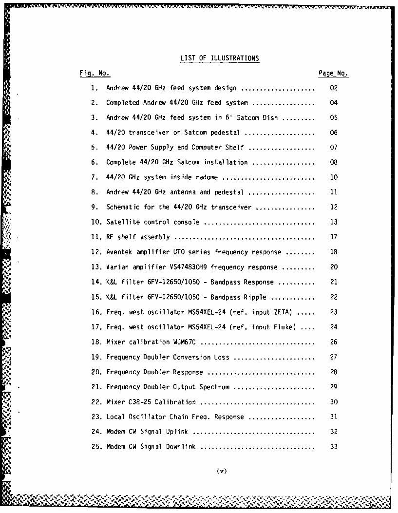
The contract was issued on 14 November 1983 and the completed
unit delivered on 31 March 1984. For this installation, the RF shelf andpower supplies are mounted adjacent to the Radome wall (Fig. 7) and fed tothe outside fixed antenna through the Radome panel. This configurationresulted in the lowest possible feed losses. The antenna installation isshown in Fig. 8. With this installation a series of experiments usingfrequency hopping and jamming techniques will be carried out over theKingsmere repeater range.
3. SYSTEM DESCRIPTION
The 44/20 GHz circuit design is shown in Fig. 9. Components to
the left of the dotted line are housed in the RF shelf mounted in theradome. Components to the right of this line are housed in the satelliteconsole room 203 (Fig. 10).
Signals fed to the radome are amplified to overcome 200 ft ofcable loss and then received by line receiver amplifiers. The signals arethen level set to satisfy the RF mixer inout requirements.
3.1 FREQUENCY AGILITY
The system allows for frequency agility in both the TX and RX
signal paths. The transmitter has provision to radiate +17 dBm of RFpower, in increments of 20 Hz steps from 43.5 GHz to 45.5 GHz into the 50dB gain antenna.
The receiver has a similar 20 Hz incremental frequency aqilityacross the 20.2 GHz to 21.2 GHz band.
The frequency agility will be provided through computer control
of the highest frequency local oscillators, in both the transmit andreceive signal paths. Both the transmit and receive chains use a doublefrequency conversion scheme with phase locked local oscillators.
_ ~ ~ .h . -- a ., - . - - - - - - - -
* 10
10
- * ..........
'. .UOWN
Figure 7 44/20 GHz svstemr inside radome

hor
* C
* 00
Q)
44

12
Ozz
Ir00.0
z go
0 CV
'T
00
z z
CID-
.4

II.
% %

3.2 SIGNAL ROUTING
Data signals, ref. signals and the local oscillator siqnalsoriginate in the satellite console room (Fig. 10) and are fed to the RFshelf in the radome. Frequency agile local oscillator signals areupconverted to the Q band and KA band frequencies via mixers and phaselocked local oscillators referenced to the 5 MHz frequency standard.
3.3 COMPONENT CODING FOR IDENTIFICATION
Major components are identified in Fig. 9 by a letter enclosed insquare brackets [--]. A list of components with their identification codeare tabulated in Table (2). The signal levels in dBm at the mixers andamplifiers in the transmit and receive chains are identified in Fig. 9.The detailed description of the system makes use of this labeling scheme.
TABLE 2
COMPONENT IDENTIFICATION CODES
[A] AMPLIFIER UTO 2022[B] AMPLIFIER UTO 1002+1003[C] AMPLIFIER UITO 2022[D] AMPLIFIER UTO 1002+1002[E] MIXER HONEYWELL SPACEKOM MODEL SMC 0510[F] MIXER HONEYWELL SPACEKOM MODEL SMC 0408[G] MIXER WATKINS - JOHNSON MODEL WJ-M67C[H] AMPLIFIER VARIAN VSU7483CH[J] FREQUENCY DOUBLER HONEYWELL SPACEKOM DK-24-26[K] AMPLIFIER VAIRAN VSC-7463CR[L] AMPLIFIER VARIAN VSX-7473MC[M] MIXER HONEYWELL SPACEKOM MODEL C20-8[N] AMPLIFIER VARIAN MODEL VS4-7483CR[P] MIXER WATKINS-JOHNSON MODEL WJ-M67C[R] MIXER HONEYWELL SPACEKON MODEL C45-7.5[S] AMPLIFIER VARIAN MODEL VSA-7405CC[T] MIXER HONEYWELL SPACEKON MODEL C38-25[U] AMPLIFIER VARIAN MODEL VSQ-7407D[W] OSCILLATOR FREQUENCY-WEST MODEL MS80OXEL-25[X] OSCILLATOR FREQUENCY-WEST MODEL MS600XEL-25[Y] OSCILLATOR FREQUENCY-WEST MODEL MS760XEL-25[Zi OSCILLATOR FREQUENCY-WEST MODEL MS54XEL-24
FILTERS WAVEGUIDE GAMMA-F CORP.FILTERS BASEBAND TUBULAR K&LWAVEGUIDE COUPLERS BAYTRONXTAL DETECTORS TRG AND NARDAREF OSC (105 MHz) ZETA MODEL 4812WAVEGUIDE SWITCH MDLANTENNA 6' DIA ALPHA TRGANTENNA 4' DIA ANDREW ANTENNADUAL FREQUENCY FEED SYSTEMS ANDREW ANTENNAPOWER SUPPLIES LAMBDA
J,, , .~ P. N .1 V 'a. N, '. N a6 S.% .'.A .. a.aa% ,.. .

15
4. SIGNAL PATH DESCRIPTION
4.1 UPLINK DATA PATH
The 700 MHz uplink data siqnal is received at the RF shelf(Fig. 9) in the radome and level set to -31 dBm at the line receiver. The
output of line receiver [B] feeds the first mixer [F] in the chain, herethe signal is mixed with a 6.3 GHz phase locked siqnal [Z] to produce a 7GHz data signal at -18 d~m. This signal is filtered and amplified [K] toset the input level for the final Q band mixer [R] at +3.5 dBm.
4.2 UPLINK LOCAL OSCILLATOR PATH
The local oscillator (LO) for mixer [R] provides the frequencyagility for the transmitter, and is derived from a computer controlledsynthesizer AIL model 360011 housed in the satcom console rack. The AILsynthesizer output is transmitted to the radome and enters the RF shelf at-6 dBm. Amplifier [A] receives this signal and provides the drive level of-3 dBm to mixer [G]. The frequency aqile LO signal is mixed with a11.340 GHz phase locked source [Y] to generate the first upconversion inthe LO chain (11.450 - 12.450) GHz. This signal is then filtered,amplified [H] and fed to a freauency doubler [J] at a +20 dBm level. Thedoubled output is attenuated to -3 dBm and applied to the second mixer [Tin the local oscillator chain. The local oscillator port of the mixer [T]is fed from a 13.6 GHz phase locked oscillator [W] at a +10 dBm level. Theoutput of mixer [T] is then filtered and amplified [S] to +7 dRm to providethe final frequency aqile signal for the Q band mixer [R].
The output of mixer [R] is filtered and applied to a solid stateHPA [U] at an input level of -3 dBm. The amplifier output is fed to the
antenna port of a 6 ft. dish (EHF satcom pedestal mode) or a 4' fixedantenna (Kinqsmere repeater range mode). The EIRP is 42.5 dBm and 37 dBmrespect ively.
4.3 DOWN LINK DATA PATH
The received signal downlink data path is filtered and fed to a
low noise mixer [M] at a nominal -71 dBm from the repeater ranqetransmitter. The LO signal at mixer [M] provides frenuency agility tode-hop the frequency hopped signals in the (20.2 - 21.2) GHz freauencyrange. The frequency agility is again provided by a second computercontrolled synthesizer AIL model 360011 housed in the satcom console rack.This signal is transmitted to the radome and is received at -9 dBm at theRF shelf.
The frequency agile signal (.810 - 1.810) is amplified [C] to 0
dBm and fed to mixer [P]. A fixed PLO [Y] at 11.340 GHz is shared by the
. ..... .. ~ ~ . *-.. .. .:.SS~...: ..- ..... \..., .... _... -. .. .... . .. .

16
uplink and downlink chain throuqh a power splitter providing a drive levelof +10 dBm to mixer [P]. The output of mixer [P] is filter amplified [N]to provide a frequency agile. LO signal (12.150 - 13.150) GHz at +10 dBmat mixer [M].
The output of mixer [MI is a fixed IF signal of 8.050 GHz whensynchronization of the received signal and the frequency aqile LO isachieved at [MI. The 8.050 GHz IF signal is filtered amplified [L] to-38.0 dBm for the next down conversion at mixer [E].
The local oscillator port of mixer [E] is fed from a 7.350 GHzPLO [X] at +10 dBm. The 700 MHz output is amplified [D] and transmitted tothe satcom console via a 200 ft. type N cable. The received signal ispower split for wideband applications or filtered and demodulated to a 70MHz IF signal for baseband demodulation and diqital processing.
5. SIGNAL CHARACTERIZATION
5.1 LOCAL OSCILLATOR STABILITY
All local oscillators (Fig. 9) used in the upconversion anddownconversion chains are phase locked to a 5 MHz frequency standard. Thisstandard is housed in the satcom console rack and sent to the RF shelf inthe radome. This 5 MHz reference is used to phase lock the ZETA oscillatormodel 4812. The output of the ZETA is 105 MHz and is used as the inputreference signal for the 11.340 GHz PLO [Y], the 6.3 GHZ PLO [Z] and the7.350 GHz PLO [X]. The 13.6 GHz PLO [W) requires a separate referencesignal (102.2255 MHz) due to a x133 multiplier ratio.
5.2 TEST ENVIRONMENT
The RF shelf assembly is shown in Fig, 11. Characterization ofthe amplifiers, filters, phase locked oscillators, and mixers was madeduring the assembly stage. The test equipment used is listed in Table 3.The RF shelf was placed in the radome and a link established from thesatcom terminal throuqh a simulated link using the Kingsmere repeaterreceiver (44 GHz) and transmitter (20 GHz) subassemblies.
Measurements of the overall system performance were recorded andsome modifications made to improve the system phase noise.
One typical plot for each qroup of several identical componentswill be shown below. Signal characterization at critical monitor points in
the uplink and downlink chain are presented along with input and outputwaveforms for the complete system.
A frequency response plot for the Aventek amplifiers [A] through[D] is shown in Fig. 12. These devices are the coaxial line receivers anddrivers for the 200' cable runs between the satcom console and the radome.
S. . . .. . ..I.. ' ' ' ' ' '. .' . '' . ' . "* . ' . ' °' . . '-'''. - " " . . - - " "." ' '.".'- o ' . '." ' . ''

17
00
do&
a,

18
N
i~CD.0
cr'
+ + >a0-
C
Cj)
LO C14
N
C-C)
+ C
,I.'

19
TABLE 3LIST OF TESt EQUIPMENT
1. Generator Sweep HP Model 8350RF Plug in 83570RF Pluq in 83592A
2. Generator Synthesized HP Model 3673A
3. Frequency Extender WJ1204-42
4. Spectrum Analyzer HP 85668
5. Power Meter HP 432A
Power Meter HP 436A
6. Freauency Synthesizer Fluke 6160B
7. Network Analyzer HP 8756AHP Plotter 7470A
Amplification of signals in the 4 GHz to 14 GHz bands make use of
Varian amplifiers [H] [K] [L] [N]. Frequency response of amplifier [H]model VSU7483CH is shown in Fig. 13.
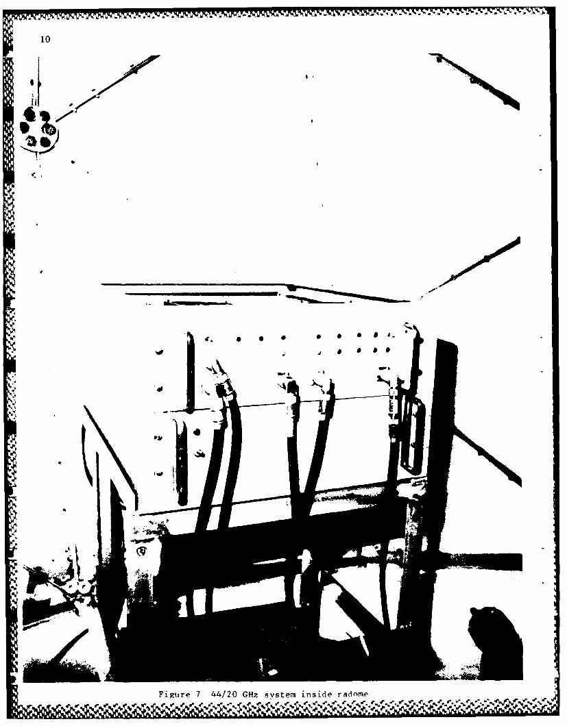
A plot for the K&L filters used in the IF signal paths ispresented in Fig. 14 and Fig. 15. The bandpass response (14) and bandpassripple (15) is typical of all IF cavity type filters used in the shelf.The local oscillators [W] [XJ [Y] [Z] are phase locked to a 5 MHz standardin the satcom console. Phase locking is achieved through the use of anintermediate phase locked oscillator ZETA (Model 4812) which supplies a105 MHz reference for these oscillators.
The phase noise at the output of the oscillators can be shown to
be directly related to the purity of the reference source. A 10 dBimprovement in signal to noise was obtained for the output of oscillator[Z] 6.3 GHz simply by substitutinq a Fluke 1066B synthesizer to supply thereference frequency 105 MHz (Fig. 16) in lieu of the ZETA 4812 PLO (Fig.17).
5.3 THE FREQUENCY AGILE LOCAL OSCILLATOR CHAIN
The uplink local oscillator chain qenerates the wideband
frequency agility (2 GHz) required by the system design. The performanceof this chain can be illustrated using the schematic diagram (Fig. 9) alonqwith the individual component characterization plots.
, "
- -"°- ~,hd. -- m LV- m 'm ~ n h i 40 .....

' 20
T P4. c( m. g
"€ L" - . ... . . . . 'I
-7-4 ri4-
S -- L C
N, rnN6J
D <-
r-,
M~ E
CD M
CD'
J Vt., 20 "
> rdIL
%% %.L " %.
, -LL . - - :P.. . .d
-.. .
= d . - , - . - d ' I i / qb I -u

21
CD N
O Lo 0*n 0
0
Lil +
0
mm M-Lf)
N
NOL 0 0
Lfl
-4
-4
+ -4
N
CD
Li--
Li U
22
o 0
ILCL+ C/,
L0..
CI) zN
0o Ulr's 0
I- >o
N CD
aa:
c'J
- + a
Wa:
a I L.
a:a
. . . . . .. . . . . . . . . . ...* I-

V*V.,jvvww~, -w w ,
23
rN :
'I-I1' *r
.- ' ~ 0
LIL
L I11
ppN. N N~ N -
%p -.. %

24
N-i1~~~ -N
Ur)
G% Il
< M
a.
u) a
iL-N a)
F- -N-
±S -0Gm3
LflZi
m NLw Q
N G -
% %W %- % %% %%

25
The calibration curve for mixer [G] (Fiq. 18) show that an inputof +3 dBm results in an output of -4 d~m. This signal is filtered, and
amplified [H] to +20 dBm. From the frequency doubler curve (Fig. 19) aninput of +22 dBm results in an output of +7.5 dBm. Thus the attenuatorbetween doubler [J] and mixer [T] is set for a 10 dR signal reduction. Thefrequency response for doubler [J] is shown in Fig. 20 and the outoutspectrum (in Fig. 21) for a fixed freauencv of 94.399 GHz.
The mixer plot C38-35 for mixer [TI (Fig. 22) shows an output of-12 dBm for an input of -6.5 dBm. This output level when applied toamplifier [S] gives an output of +7.5 dBm, which is the correct signallevel for the LO Port of mixer FR].
The frenuency response of the frequency agile local oscillatorchain is shown in Fig. 23.
6. SYSTEM PERFORMANCE TESTS
The system was checked in a simulated link made using theKingsmere RX subassembly and the Kinasmere TX subassembly mounted in theRadome at CRC. This allowed a laboratory test of the 44/20 GHz link beforeinstaliation of the subassemblies on the 80' tower at the repeater site 16
km from CRC.
The 700 MHz CW input siqnal derived from the satcom console isshown in Fig. 24. This input is attenuated to -31 dBm at the RF shelf inthe radome. The recovered 700 MHz downlink signal (Fiq. 2S) was measuredin the radome at the RF shelf IF output nort.
6.1 Tx 43.5 GHz PHASE NOISE
The transmitter outout of 43.5 GHz in the normal circuitconfiguration was plotted through a 20 dB coupler (Fig. 26). In anexperiment to try to improve the 43.5 GHz transmit siqnal to noise ratiothe modem 700 MHz IF siqnal and the ZETA 105 MHz reference locking signalwere disconnected. Two separate Fluke synthesizers model 1066B were placedbeside the equipment and used to generate the modem cw 700 MHz and thereference 105 MHz signals. A comparison of the transmitter outnuts(Fig. 26) and (Fig. 27) shows a 12 dB imorovement over the normalconfiquration.
The 20 GHz receiver has orovision for injecting a calibrationsignal through a 3 port wavequide switch. A calibration curve for thereceiver (Fig. 28) was made by injectinq a 20.8 GHz sional into thereceiver in the radome and measuring the output in the console room at 700MHz.
6.2 KINGSMERE EXPERIMENTS
The 44/20 GHz system has been tested over the Kinqsmere repeaterrange and error free data has been passed from data rates of 75 baud to19.2 Kbps.

S 26
Co
C--I
II
ZH 0G';4 WP md;dn
* J6

27
7D -0
CfCu
CD Cu
- LLLii CD
0- l0
- L3
CDc
C.) - L U~
.r W- .1 , inccJZ .

28
C94
KICU
LLO
CL)m l1
CD c
C-. L) C
CL .3 Cij
0.)
0u
wep indno HiM~

29
10
oj -- ,.,,
UU
0' ,0 -" " 4,',
-C-
0))r
1-....i-'' - .
0)c
C') N U
(,j.. .. . e r .? " Il
UJ ] ------ _
,.t-, - - . 4)
, -< 0. . --- -. .
I --*,---- - .t--".4-; .j
.4[ ' 4.1" ,-- L] t
LI. " "% ,"•"% % , "% * " """% % "- ."% """% % % ' *" - ,% " % % " C ')' 1 " ' -

30
Icu
Lc-iLLO
I C
RI 0 E=
C r-4
LDDLr)J
CuI
LL7-
C144
wep ;nd;nj JAmOd

31
LO
C'C2
0 0
C.)
(Y)
lulff~lInO DA
A A

32
N T-I E
Lts ' ID U
m ONX
0) 1 uI
V-4-N
m -__ r_
N
LUn
N N N~
2: 1i 1n CC -
-U E
0)
0 LL (0 w
co - - 0---
Q Q)CJ

33
G) I A
I, I
F- IIId
IT) I 4
0) mTh
LOO
L)i T I*~ ~ E'1I
r-4
:i1 (D10
..- Cp Of
co N

S 34
N; -m -f-- 0V'V ~
J)N Q
< m
I U)
I I
NI N
CTI
D E-
L
N LIJ fm 00 G I.JE I-
TI .~. 0 S
~Z N -0J~ IwfJ

N - N
ox
) N X zOI _ _ <_ _ _ _
U) I
(14)
mom
L9
Zz (0
0 Q)E
D E G WCD) 0)u
O(S '.t I a) m__
WW <U)t )Q
N~ X U)W (D JE W
I1. 0(I N>3 N m (0 0 z
Q- z NUa

S 36
jcDu
C)-
r---i -I
coo
-C-D
- L LJ -
-4 v-I
C-v-
C> I
4-jF
I I I I I£O~~~~~~~~~~r WOJU TSOO~J 1 WP))zd;dnsoI
Cl

37
During the summer of 1984 some propagation experiments werecarried oijt. Plots of attenuation for the 44 GHz TX path and the 20 GHzreceive raths are shown in Fig. 29. Future experiments will include narrowband frequency hopping trials, signal jamming experiments and rainattenuation measurements.
7. CONCLUSIONS
7.1 The 44/20 GHz system has been successfully tested over the
Kingsmere repeater link and some limited experiments conducted. Theseparation between baseband equipment and the RF shelf some 200 ft. willpresent some problems when wideband frequency hopping 2 Gz isimplemented. The cable attenuation over the .610 to 1.610 GHz Hopping band
will not be a constant and will affect the amplitude of the signal at the Qband mixer. To solve this problem, the fast hopping frequency synthesizermay have to be housed in the radome adjacent to the 44/20 GHz shelf.Improvements in signal to noise of the system could be made through theelimination of 200 ft. cable runs and placement of baseband signalprocessing equipment in the radome.
8. ACKNOWLEDGEMENTS
The author gratefully acknowledges the contributions and help
given by Mr. J.D. Lambert, Mr. D. Sim, Mr. R. Addison and the model shopsupport at CRC. Mr. Addison was seconded to the Space Systems Directorateat CRC from the Defense Electronic Directorate, Defence ResearchEstablishment Ottawa.
9. REFERENCES
1. LES 8/9-36/38 GHz Ground Terminal, A.H. McEwen and J.L. Pearce, CRCReport No. 1381, Ottawa, Sept. 1983, TRG
pp%'p' ' .. ,_m ._W _ _''" .. # - _ . ' v -- • . ', ,, . '- v '- , 'o , .- - - - - o - o . - - - ,, o . , . . .
U. _ :

38
4-jJ
cim
cDc
Ei CLcu ____ Cu
c4-:C-~
4-) C~
______________cu Nr
C~ cu
C~C.
cu
cu
-G 0 0 0 00) u
P,0A w c uc
(w9P) O-4

39
A
a3
.1
APPENPIX A
Primary Antenna Pattern
P.'.-A
P.'-A
a~-A'I,
S's
'C.'.,
*5%
4'.
'.5.
.'.5'-
5*-'5-~
'pa'.
'p
-a'.
&
5~a-
~ -~ a55 ~> .5. 5'.

4+0
---- -----
Lifl
-0 --
.. . .. ......
..... ..................... .
..... ... .. -- -- --- : --- -- ' .. ......
m ... .... ... ... ... .-1
..
7 7- ---- -------
- - - - - - - -- - - - -
.......... ....... ....... ...........

-
----
w : - - - - - -- -- -- . 7
.. .. . .. C4(
4. - -- -- -- - - - ------- - ----- -
. . .. . . .. . . . . . .. ...
... ... ..... .. ... .. -- -- t -- -- -- -- - - - -
.. ... ...
w - ,-------------- - -- -
. . .. .. . . . . .:...
.. . .. . . ..

W-.F-JF-kp -. -J-% -P . . . . . . . . . .
42
C5
...... ...
!:. .: : : : . . .. .: . . .
7777. .. . .. . . ... . P4........ .. I., . . ............
.. . .. . .:..7 . . .
Si -. -- . .- ---- --- -- --
. .. ....
....... ..... ...
.. ... ..
a. .P d* - * - . . . .. . .. . . . . . .,
5 .F ~............. .. .. : . .S- . .
5. ~ 77777-7-. '. - ~ . V *'S ~ *~ .. 1 p --------........ .......... '

4 3
------ ---
~~ ii
77 .
mU - ---- 7
777- ------ - ---- - ---------- 7M
.- . ....- .. .. ..--..-
I,~~77
---. -
--*- *
-- --
7-
._ .1 .__..__..
..- .T t . ----- --
-f j jAjj ; L -- e e- %- -, r-- F
AA~..

44
b-io
0. --_ --- - -- - - 7 - . - _ _ _ _ _ _
0z- --.. ........
vi . .....
4 ~ >.l0 z.
.- .__ ..
. .
7- -
I .a
E-4
a 0
m . . . .
m .. . .
. .
-~~ -.. - --. ..-- -
... .. T
~~-7
OP~ %

45
7 - -- ---
. . . ... I n
.- .. .....
Ii.-A
O'C -. 11
.. . .. .- -

46 -I_ _ _ _ _
4 3AIJYe3 a 4
* I :. ........-E 0. 1
...... ... . .
.7, +1__
L 7C
4;..
!* T IA3p
wi.4
JI.
%. % Ij-5 :*:
g-l --- a-- .I-*-'- - _m%&% 4 % -!" -~ - 4. 4

- I
rw-.1
% % I .
0I .-

Rp~wrrt
-.- ,-: -
.. .. . . . . . . . .
- E-
E- 11
..0 ...-....... t . . . ... . .. . ... ,-..
... .. ... . . . .
. ..............
'.e e +K1 J J

-49
rNf 31YO 0 L)f '
.............
.. ... ......
. ..... . ......
r4 ct
Z4
d::M.71-7.,
.. ... ..... .- .
7 7;
t . ._...
Iw I
'~~~~~~~ .. ..s.... .._ A .. m.
%p % .. %.,I I ^% S %
K-.&;Pmf:. e In!- "l
: 'NYA~jzoy<t

50
V. a ill
ILL
I-. X U)
.... .... ... ....... - - - - - -.
Il ,.
LL-j
. . . . . . .. . . ...... . ... . .
Ir_ -: . . . ' . . .
'Il22 2 -f 4 l ____

- '7---7 .zr -J
u
I 1
. . .. ....
.... ..... . ......
K , K7
1 .......... 7-
4 04
Sb7'
% % 1 % %'
I%-%

53
APPENDIX B
4' Diameter Antenna Patterns
%-- V

* - ~ - - ~ - . ~ ~ & ~. ~ M ~. ~ ~ ~w' -.i* v
IC,
N
3-.3--.
x
3-C, C..C
ow (C
* ~- 4C,z
C.
(C
.3 .4
N q
.4
* .7.
.4
*7
.3.
I- I I I
0 0 0 I(9P) AVM 3N0 ~MOd 3AI1V~~bj

00
.j
e Id rw ,J

b 04
.4.4N0
*% %

57
.C.
'UU
C.,
.9.
-.9
(OP AN N 3~ Ailt
%I
8.7 A

UNCLASSIFIED -59-
SECURITY CLASSIFICATION OF FORM(highest classification of Title, Abstract, Keywords
DOCUMENT CONTROL DATA(Security classification of titl, body of abstract and indexin annotation must be entered when the overall document is classified)
1. ORIGINATOR (the name and address of the organization preparing the document 2. SECURITY CLASSIFICATIONOrganizations for whom the document was prepared. e.g. Establishment sponsoring (overall security classification of the document.a contractor's report, or tasking agency, are entered in section B.) including special warning terms if applicable)
Communications Research Center
Satellite Communications Directorate
3701 Carling Avenue, Ottawa, Ontario, Canada U3. TITLE (the complete document title as indicated on the title page. Its classification should be indicated by the appropriate
abbreviation (SC,R or U) in parentheses after the title.)
44/20 GHz Ground Terminal
4. AUTHORS (Lost name, first name, middle initial. If military, show rank. e.g. Doe, Mal. John E.)
McEwen, A.H.
5. DATE OF PUBLICATION (month and year of publication of 6a. NO OF PAGES (total 6b. NO. OF REFS (total cited indocument) containing information. Include document)
September 1987 Annexes, Appendices, etc.) 156
7. DESCRIPTIVE NOTES (the category of the document, e.g. technical report, technical note or memorandum. If appropriate, enter the type ofreport, e.g. interim, progress, summary, annual or final. Give the inclusive dates when a specific reporting period is covered.)
DREO Technical Report
8. SPONSORING ACTIVITY (the name of the department project office or laboratory sponsoring the research and development. Include theaddress.)
DREO via CRC
9a. PROJECT OR GRANT NO. (if appropriate, the applicable research 9b. CONTRACT NO. (if appropriate, the applicable number underand development project or grant number under which the document which the document was written)was written. Please specify whether project or grant)
32A53 0830 00000
10& ORIGINATOR'S DOCUMENT NUMBER (the official document 1Ob. OTHER DOCUMENT NOS. (Any other numbers which maynumber by which the document is identified by the originating be assigned this document either by the originator or by theactivity. This number must be unique to this document) sponsor)
CRC REPORT 1428
1 1. DOCUMENT AVAILABILITY (any limitations on further dissemination of the document, other than those imposed by security classification)
(X) Unlimited distribution
( ) Distribution limited to defence departments and defence contractors; further distribution only as approved( ) Distribution limited to defence departments and Canadian defence contractors; further distribution only as approvedi ) Distribution limited to government departments and agencies; further distribution only as approved
( Distribution limited to defence departments; further distribution only as approved
, I Other (please specify):
- 12. DOCUMENT ANNOUNCEMENT (any limitation to the bibliographic announcement of this document This will normally correspond tothe Document Availabilty (11). However, where further distribution (beyond the audience specified in 11) is possible, a wider
,.5 announcement audience may be selected.)
1Same as 11.
UNCLASSIFIED
SECURITY CLASSIFICATION OF FORM
DCD03 9/04/87
% •0'1|

-60- UNCLASSIFIED
SECURITY CLASSIFICATION OF FORM
1 3. ABSTRACT ( a brief and factual summary of the document. It may also appear elsewhere in the body of the document itself. It is highlydesirable that the abstract of classified documents be unclassified. Each paragraph of the abstract shall begin with an indication of thesecurity classification of the information in the paragraph (unless the document itself is unclassified) represented as (S), (C), (R), or 1UIt is not necessary to include here abstracts in both official languages unless the text is bilingual).
The design and construction of an EHF SATCOM terminal totransmit in the mobile satellite (43.5 - 45.5) GHz band andreceive in the fixed satellite space to earth (20.2 - 21.2) GHzband is described. Characterization plots for individual RF systemcomponents and test results of the complete terminal operating overa 16 km repeater range are shown.
14. KEYWORDS. DESCRIPTORS or IDENTIFIERS (technically meaningful terms or short phrases that characterize a document and could behelpful in cataloguing the document. They should be selected so that no security classification is required. Identifiers, such as equipmentmodel designation, trade name, military project code name, geographic location may also be included. If possible, keywords should be selectedfrom a published thesaurus. e.g. Thesaurus of Engineering and Scientific Terms (TEST) and that thesaurus identified. If it is not possible toselect indexing terms which are Unclassified, the classification of each should be indicated as with the title.)
- spread spectrum
- digital satellite communications
- EHF satellites
- frequency hopping
- experimental satcom
UNCLASSIFIED
SECURITY CLASSIFICATION OF FORM
W fu ~ .% .*A~ . *0

Hwob
.7r/ C...?