Embed Size (px)
Citation preview

INSTRUCTION MANUAL CODE 80315 REV B Octubre 2019 (It can be modified without notice) Page: 1
J.P. SELECTA s.a.u. Ctra. NII Km 585.1 Abrera 08630 (Barcelona) España Tel 34 937 700 877 Fax 34 937 702 362 e-mail: [email protected] - website: http://www.jpselecta.es
CENTRÍFUGAS - CENTRIFUGES
CENTRONIC BLT 7001768CENTROFRIGER BLT 7001769CENTROMIX BLT 7002556MIXTASEL BLT 7002576

J.P. SELECTA s.a.u. Ctra. NII Km 585.1 Abrera 08630 (Barcelona) España Tel 34 937 700 877 Fax 34 937 702 362 e-mail: [email protected] - website: http://www.jpselecta.es
INSTRUCTION MANUAL CODE 80315 REV B October 2019 (It can be modified without notice) Page: 2
Indice1 Seguridad......................................................................................................................................................31.1 Iconos de seguridad..................................................................................................................................................................31.2 Cualificación del personal ..........................................................................................................................................................32 Información general .....................................................................................................................................33 Especificaciones técnicas .............................................................................................................................44 Lista de embalaje .........................................................................................................................................44.1 Contenido estándar del paquete ................................................................................................................................................45 Introducción .................................................................................................................................................56 Instalación....................................................................................................................................................56.1 Emplazamiento .........................................................................................................................................................................56.2 Primera apertura de la tapa y apertura de emergencia ................................................................................................................56.3 Conexión a la red eléctrica ........................................................................................................................................................66.4 Colocación del cabezal ..............................................................................................................................................................67 Funcionamiento ............................................................................................................................................67.1 Pantalla de Ajustes ...................................................................................................................................................................87.2 Programación directa y funcionamiento ......................................................................................................................................87.3 Mensaje de error ......................................................................................................................................................................87.4 Programación de perfiles ..........................................................................................................................................................9
Index1 Safety..........................................................................................................................................................101.1 Safety icons............................................................................................................................................................................101.2 Personnel qualification ............................................................................................................................................................102 General information ...................................................................................................................................103 Technical specifications .............................................................................................................................114 Packing List ................................................................................................................................................114.1 Standard package content .......................................................................................................................................................115 Introduction ...............................................................................................................................................126 Installation .................................................................................................................................................126.1 Location.................................................................................................................................................................................126.2 First lid opening and emergency opening .................................................................................................................................126.3 Connection to the mains .........................................................................................................................................................136.4 Rotor positioning ....................................................................................................................................................................137 Operation ....................................................................................................................................................137.1 Setting screen ........................................................................................................................................................................157.2 Direct programming and operation ..........................................................................................................................................157.3 Error message ........................................................................................................................................................................157.4 Profile programming ...............................................................................................................................................................16
INSTRUCTION MANUAL CODE 80315 REV B Octubre 2019 (It can be modified without notice) Page: 3
J.P. SELECTA s.a.u. Ctra. NII Km 585.1 Abrera 08630 (Barcelona) España Tel 34 937 700 877 Fax 34 937 702 362 e-mail: [email protected] - website: http://www.jpselecta.es
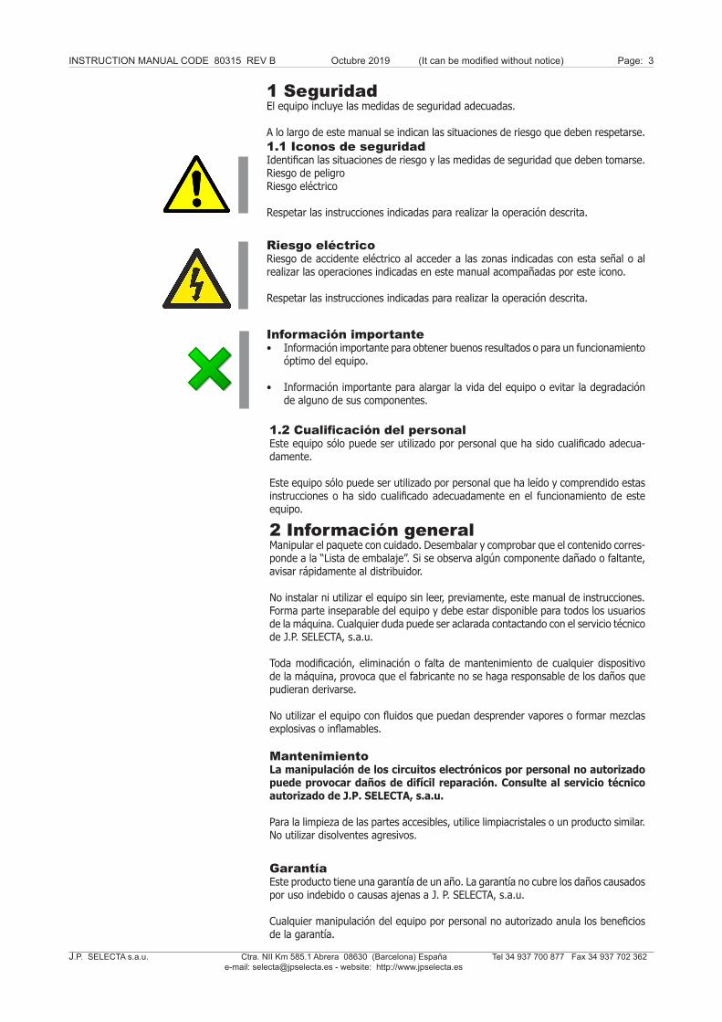
1 SeguridadEl equipo incluye las medidas de seguridad adecuadas.
A lo largo de este manual se indican las situaciones de riesgo que deben respetarse.1.1 Iconos de seguridadIdentifican las situaciones de riesgo y las medidas de seguridad que deben tomarse.Riesgo de peligroRiesgo eléctrico
Respetar las instrucciones indicadas para realizar la operación descrita.
Riesgo eléctricoRiesgo de accidente eléctrico al acceder a las zonas indicadas con esta señal o al realizar las operaciones indicadas en este manual acompañadas por este icono.
Respetar las instrucciones indicadas para realizar la operación descrita.
1.2 Cualificación del personalEste equipo sólo puede ser utilizado por personal que ha sido cualificado adecua-damente.
Este equipo sólo puede ser utilizado por personal que ha leído y comprendido estas instrucciones o ha sido cualificado adecuadamente en el funcionamiento de este equipo.
Información importante• Información importante para obtener buenos resultados o para un funcionamiento
óptimo del equipo.
• Información importante para alargar la vida del equipo o evitar la degradación de alguno de sus componentes.
2 Información generalManipular el paquete con cuidado. Desembalar y comprobar que el contenido corres-ponde a la “Lista de embalaje”. Si se observa algún componente dañado o faltante, avisar rápidamente al distribuidor.
No instalar ni utilizar el equipo sin leer, previamente, este manual de instrucciones. Forma parte inseparable del equipo y debe estar disponible para todos los usuarios de la máquina. Cualquier duda puede ser aclarada contactando con el servicio técnico de J.P. SELECTA, s.a.u.
Toda modificación, eliminación o falta de mantenimiento de cualquier dispositivo de la máquina, provoca que el fabricante no se haga responsable de los daños que pudieran derivarse.
No utilizar el equipo con fluidos que puedan desprender vapores o formar mezclas explosivas o inflamables.
MantenimientoLa manipulación de los circuitos electrónicos por personal no autorizado puede provocar daños de difícil reparación. Consulte al servicio técnico autorizado de J.P. SELECTA, s.a.u.
Para la limpieza de las partes accesibles, utilice limpiacristales o un producto similar. No utilizar disolventes agresivos.
GarantíaEste producto tiene una garantía de un año. La garantía no cubre los daños causados por uso indebido o causas ajenas a J. P. SELECTA, s.a.u.
Cualquier manipulación del equipo por personal no autorizado anula los beneficios de la garantía.

J.P. SELECTA s.a.u. Ctra. NII Km 585.1 Abrera 08630 (Barcelona) España Tel 34 937 700 877 Fax 34 937 702 362 e-mail: [email protected] - website: http://www.jpselecta.es
INSTRUCTION MANUAL CODE 80315 REV B October 2019 (It can be modified without notice) Page: 4
4 Lista de embalaje4.1 Contenido estándar del paquete
El equipo estándar consta de los siguientes componentes:
- Centrífuga CENTRONIC BLT: 7001768- Centrífuga CENTROFRIGER BLT: 7001769- Centrífuga CENTROMIX BLT: 7002556- Centrífuga MIXTASEL BLT: 7002576- Cable de conexión red 7140- Llave tuerca cabezales* 5377 (*sólo para los modelos: CENTRONIC BLT CENTROFRIGER BLT MIXTASEL BLT)- Manual de instrucciones 80315
3 Especificaciones técnicasTensión de alimentación 115/230V 50/60 Hz según se indi-que en la placa de características de la máquina.
Código: 7001768 7001769 7002556 7002576
Dimensiones (mm): Alto Ancho Fondo 340x410x540 340x410x710 230x300x350 340x390x440
Potencia (W): 440 960 180 210
Velocidad máx. (rpm): 13500 15300 4400 4200
RCF máx.: (Según cabezal) 19048 23700 2791 3151
Peso (kg): 22 39 12 22

INSTRUCTION MANUAL CODE 80315 REV B Octubre 2019 (It can be modified without notice) Page: 5
J.P. SELECTA s.a.u. Ctra. NII Km 585.1 Abrera 08630 (Barcelona) España Tel 34 937 700 877 Fax 34 937 702 362 e-mail: [email protected] - website: http://www.jpselecta.es
6 Instalación
6.1 Emplazamiento
• Situar el aparato cerca de una toma de corriente adecuado a su consumo sobre una superficie plana (nivelada) y suficientemente robusta para soportar el peso del equipo y eventuales vibraciones.
• La superficie de apoyo debe permitir la adherencia de las patas de la centrífuga.
• Dejar un espacio libre de 30 cm. alrededor (Ver indicación de peligro).
• Este equipo puede provocar vibraciones que afecte a otros equipos cercanos.
• No instalar la centrífuga cerca de fuentes de calor o en lugares donde esté expuesta a la luz solar, ya que podría afectar a la regulación de temperatura.
• Colocar la tetina suministrada en la salida (16) y conectar una manguera para desaguar los condensados.
5 IntroducciónLa centrífuga tiene un motor de inducción libre de mantenimiento y un nivel sonoro máximo de 60 dBA. Dispone de una cámara interna de seguridad y una cubeta, contratapa en acero inoxidable.
El circuito electrónico está controlado por un microprocesador que controla los parámetros de funcionamiento: velocidad, aceleración, freno, RCF, temperatura y tiempo de funcionamiento. Tiene capacidad para almacenar hasta 10 programas de funcionamiento.
ESPACIO LIBRE ALREDEDOR DE LA CENTRIFUGA
Zona de seguridad:
Dejar un espacio libre de 30 cm. alre-dedor de la centrífuga.
Con la centrífuga en marcha:
• No depositar sustancias peligrosas en la zona de seguridad.
• El personal debe estar fuera de la zona de seguridad.
NO INSTALAR EL APARATO EN ATMÓSFERAS EXPLOSIVAS O EN LUGARES DONDE SE USEN O ALMACENEN SUSTANCIAS SUSCEPTIBLES DE FORMAR MEZCLAS EXPLOSIVAS O INFLAMABLES.
6.2 Primera apertura de la tapa y apertura de emergencia
Al recibir la centrífuga, el cable de conexión de red se encuentra en el interior de la cubeta y, por tanto, la única manera de abrir es seguir las siguientes indicaciones:
- Extraer los tapones de plástico laterales de la máquina.- Tirar cuidadosamente de ambos tapones y la tapa se abrirá.
UTILICE ESTE SISTEMA DE APERTURA, SÓLO PARA UNA APER-TURA DE EMERGENCIA.
No usar nunca el dispositivo de apertura de emergencia cuando el motor esté girando

J.P. SELECTA s.a.u. Ctra. NII Km 585.1 Abrera 08630 (Barcelona) España Tel 34 937 700 877 Fax 34 937 702 362 e-mail: [email protected] - website: http://www.jpselecta.es
INSTRUCTION MANUAL CODE 80315 REV B October 2019 (It can be modified without notice) Page: 6
6.3 Conexión a la red eléctrica
Asegúrese que el equipo se conecta a una tensión de red que coincide con la indicada en la placa de características.
No utilice el equipo sin estar conectada la toma de tierra.
Utilice sólo el cable suministrado para la conexión de red.
Asegúrese de hacer encajar la chaveta del eje del motor en su alojamiento.
Apriete firmemente la tuerca del cabezal con la llave suministrada (sólo en los modelos Centronic BLT, Centrofriger BLT y Mixtasel BLT).
Colocar los adaptadores y los tubos de forma equilibrada.
6.4 Colocación del cabezal
Antes de poner en marcha la centrífuga, asegúrese de haber colocado el cabezal de forma correcta ya que de lo contrario se podrían producir daños en el equipo.
7 FuncionamientoTodas las funciones de equipo se establecen mediante la pantalla táctil. Presionar suavemente con el dedo en el centro de cada icono, la accion se realiza al soltar el dedo de la pantalla.
Al poner en marcha el equipo se muestra la pantalla de inicio.
• Ajustes: - Hora y fecha: menú para establecer la fecha y la hora.
• Programación - Permite programar el perfil de centrifugación, definiendo veloci-dades, tiempos y rampas de aceleración y frenado.
• Trabajo - Permite seleccionar y poner en marcha un perfil de centrifugación.
AJUSTESSETTINGS
PROGRAMACIÓNPROGRAMMING
TRABAJOTASK

INSTRUCTION MANUAL CODE 80315 REV B Octubre 2019 (It can be modified without notice) Page: 7
J.P. SELECTA s.a.u. Ctra. NII Km 585.1 Abrera 08630 (Barcelona) España Tel 34 937 700 877 Fax 34 937 702 362 e-mail: [email protected] - website: http://www.jpselecta.es
Esquema de pantallas:
TRABAJO
AJUSTES PROGRAMACIÓN
AJUSTES
ROTOR FECHA Y HORA ESTANDAR 00 / 00 / 005000 rpm 00 : 00 Idioma ºC
PRG 00Ramp UP rpm Time 00:00 0 00:00 00:00 0 00:00 00:00 0 00:00 00:00 0 00:00 00:00 0 00:00 00:00
Para cambiar de modo, pulsar :
Selección de la temperatura de trabajoen el modeloCENTROFRIGER BLT
RCFOPEN
PRG00
RAMP00:00
SET 0
SET00:00
Pantalla de trabajo con funcionamiento directo.(En la propia pantalla se establece tiempo, rpm, etc...)
Pantalla de trabajo con funcionamiento de perfíl de velocidad y rampas de aceleración y frenado.
RCF
OPEN
00:00 00:00RAMP RAMP
hh:mm
RPM
7001407
SET
00:00 hh:mm
0+25 ºC
RPM
rpm

J.P. SELECTA s.a.u. Ctra. NII Km 585.1 Abrera 08630 (Barcelona) España Tel 34 937 700 877 Fax 34 937 702 362 e-mail: [email protected] - website: http://www.jpselecta.es
INSTRUCTION MANUAL CODE 80315 REV B October 2019 (It can be modified without notice) Page: 8
Fig 7.1. Pantalla de error
AJUSTES
ROTOR FECHA Y HORA ESTÁNDAR 00 / 00 / 005000 rpm 00 : 00 Idioma ºC
7.1 Pantalla ajustes
- Actualizar fecha, hora. Pulsar sobre el panel de Fecha y Hora.
Utilizar las teclas:
y aceptar pulsando sobre De forma similar: - Seleccionar el Idioma. - Seleccionar la Temperatura de trabajo.
7.2 Programación directa y funcionamiento
- Pulsar sobre el display RPM.
- Pulsar sobre para establecer las RPM.
- Pulsar sobre SET para establecer los minutos/horas de operación.
- Si es necesario, establecer en «RAMP» los tiempos de acelera-ción de frenado:
• RAMP : Tiempo de aceleración hasta las rpm de consigna.• RAMP : Tiempo de frenado.
(Estableciendo minutos de rampa) Un tiempo 00. indica lo más rápido posible.
Pulsar para iniciar la centrifugación.
La misma pantalla indica la evolución del proceso de centrifugación.
Una vez finalizada la centrifugación, abrir la tapa con:
7.3 Mensaje de error
Cualquier incidencia de funcionamiento, provoca un mensaje de error.
OPEN
Selección de la temperatura de trabajoen el modeloCENTROFRIGER BLT
RCF
OPEN
00:00 00:00RAMP RAMP
hh:mm
RPM
7001407
SET
00:00 hh:mm
0+25 ºC
RPM
rpm
INSTRUCTION MANUAL CODE 80315 REV B Octubre 2019 (It can be modified without notice) Page: 9
J.P. SELECTA s.a.u. Ctra. NII Km 585.1 Abrera 08630 (Barcelona) España Tel 34 937 700 877 Fax 34 937 702 362 e-mail: [email protected] - website: http://www.jpselecta.es
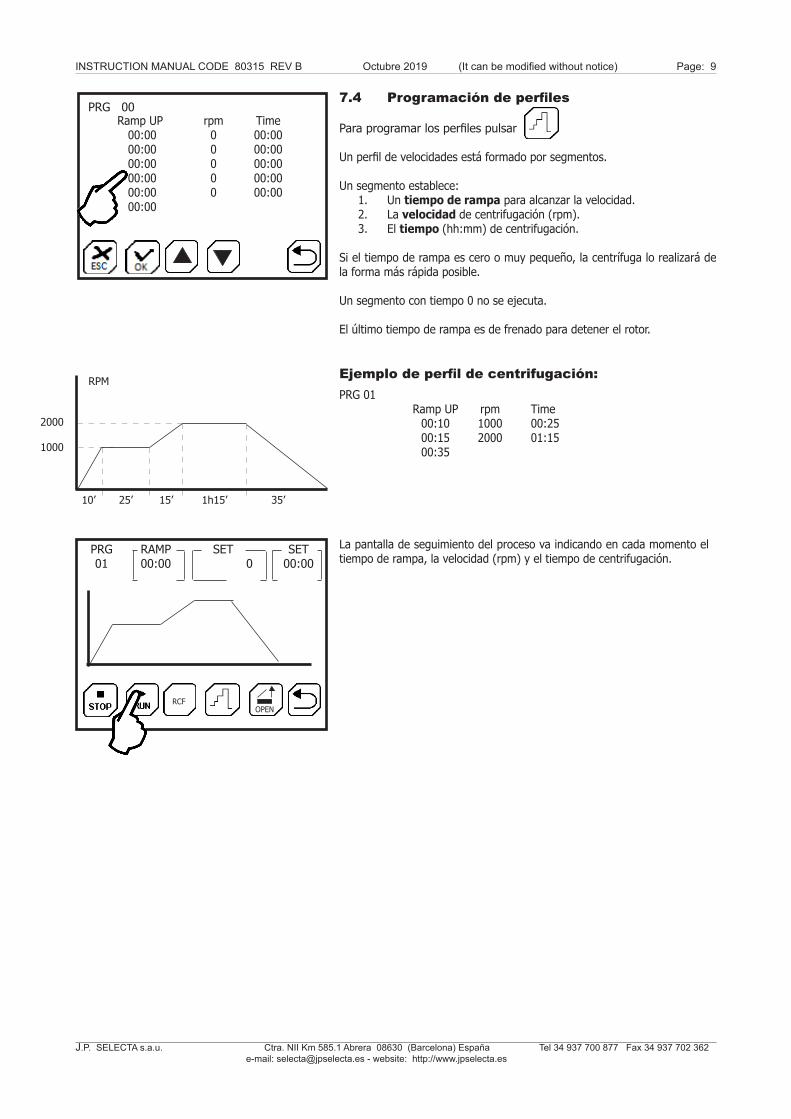
7.4 Programación de perfiles
Para programar los perfiles pulsar
Un perfil de velocidades está formado por segmentos.
Un segmento establece: 1. Un tiempo de rampa para alcanzar la velocidad. 2. La velocidad de centrifugación (rpm). 3. El tiempo (hh:mm) de centrifugación.
Si el tiempo de rampa es cero o muy pequeño, la centrífuga lo realizará de la forma más rápida posible.
Un segmento con tiempo 0 no se ejecuta.
El último tiempo de rampa es de frenado para detener el rotor.
Ejemplo de perfil de centrifugación:
La pantalla de seguimiento del proceso va indicando en cada momento el tiempo de rampa, la velocidad (rpm) y el tiempo de centrifugación.
PRG 01 Ramp UP rpm Time 00:10 1000 00:25 00:15 2000 01:15 00:35
PRG 00Ramp UP rpm Time 00:00 0 00:00 00:00 0 00:00 00:00 0 00:00 00:00 0 00:00 00:00 0 00:00 00:00
10’ 25’ 15’ 1h15’ 35’
1000
RPM
2000
RCFOPEN
PRG01
RAMP00:00
SET 0
SET00:00

J.P. SELECTA s.a.u. Ctra. NII Km 585.1 Abrera 08630 (Barcelona) España Tel 34 937 700 877 Fax 34 937 702 362 e-mail: [email protected] - website: http://www.jpselecta.es
INSTRUCTION MANUAL CODE 80315 REV B October 2019 (It can be modified without notice) Page: 10
1 SafetyThe equipment includes appropriate safety measures.Risky situations that must be respected are indicated along this manual.
1.1 Safety iconsThe safety icons identify the risky situations and the safety measures that must be taken. Risk of dangerElectrical risk
Respect the indicated instructions to perform the operation.
Electrical risksRisk of electrical accident when accessing the areas indicated by this sign or when performing the operations indicated by this icon in this manual.
Respect the indicated instructions to perform the operation.
1.2 Personnel qualificationThis equipment can only be used by personnel who have been properly qualified.
This equipment can only be used by personnel who have read and understood these instructions or who have been properly qualified in the operation of this equipment.
Important information• Important information for good results or for an optimum equipment operation.
• Important information to extend life of the equipment or to prevent degradation of any of the components.
2 General informationHandle the package with care. Unpack and check that the contents coincides with the “Packing List”. If any part is damaged or missing, please advise the distributor immediately.
Do not install or use the equipment without previously reading this instructions manual. It is an inseparable part of the equipment and should be available to all users of the machine. Any questions can be clarified by contacting J.P. SELECTA’s technical service.
Any modification, deletion or lack of maintenance of the device could cause damages. The manufacturer is not liable for the damages that may arise.
Do not use the equipment with fluids which can give off vapours or form explosive or flammable mixtures.
MaintenanceManipulation of electronic circuits by unauthorized persons may cause damages difficult to repair. Check with J.P. SELECTA’s technical service.
To clean the accessible parts, use cleaner or a similar product. Do not use aggressive solvents.
GuaranteeThis product is guaranteed for one year. The warranty does not cover damages caused by an improper use or causes beyond J. P. SELECTA, s.a.u.
Any manipulation of the equipment by an unauthorized personnel cancels the warranty benefits.

INSTRUCTION MANUAL CODE 80315 REV B Octubre 2019 (It can be modified without notice) Page: 11
J.P. SELECTA s.a.u. Ctra. NII Km 585.1 Abrera 08630 (Barcelona) España Tel 34 937 700 877 Fax 34 937 702 362 e-mail: [email protected] - website: http://www.jpselecta.es
4 Packing List4.1 Standard package content
The standard equipment consists of the following components:
- Centrifuge CENTRONIC BLT: 7001768- Centrifuge CENTROFRIGER BLT: 7001769- Centrifuge CENTROMIX BLT: 7002556- Centrifuge MIXTASEL BLT: 7002576- Network connection cable: 7140- Rotor nut wrench*: 5377 (*only for models: CENTRONIC BLT CENTROFRIGER BLT MIXTASEL BLT)- Instructions manual 80315
3 Technical specificationsVoltage supply 115/230V 50/60 Hz as indicated in the machine’s features plate.
Code: 7001768 7001769 7002556 7002576
Dimensions (mm): Height x Width x Depth 340x410x540 340x410x710 230x300x350 340x390x440
Power (W): 440 960 180 210
Max speed (rpm): 13500 15300 4400 4200
Max RCF: (Depending on the rotor) 19048 23700 2791 3151
Weight (kg): 22 39 12 22

J.P. SELECTA s.a.u. Ctra. NII Km 585.1 Abrera 08630 (Barcelona) España Tel 34 937 700 877 Fax 34 937 702 362 e-mail: [email protected] - website: http://www.jpselecta.es
INSTRUCTION MANUAL CODE 80315 REV B October 2019 (It can be modified without notice) Page: 12
6 Installation
6.1 Location
• Place the equipment near a power socket suitable for consumption and over a flat level surface and strong enough to support the equipment weight and possible vibrations.
• The surface must allow the adherence of the centrifuge legs.
• Leave a free space of 30 cm. around it (See danger indication).
• This equipment can cause vibrations that could affect other nearby equipments.
• Do not install the centrifuge near heat sources or in places where it is exposed to direct sunlight, as this may affect temperature regulation.
• Place the nipple provided in outlet (16) and connect to a hose to drain conden-sates.
5 IntroductionThe centrifuge has an induction motor maintenance free and a maximum noise level of 60 dBA. It has an internal security camera and a bucket, stainless steel cover.
The electronic circuit is controlled by a microprocessor that controls the operating parameters: speed, acceleration, braking, RCF, temperature and operating time. It can store up to 10 operating programs.
FREE SPACE AROUND CENTRIFUGE
Safety zone:
Leave a free space of 30 cm. around the centrifuge.
With the centrifuge running:
• Do not place hazardous substances in the security area.
• The staff should be outside the safe-ty area.
DO NOT INSTALL THE EQUIPMENT IN EXPLOSIVE ATMOSPHERES OR PLA-CES WHERE SUBSTANCES LIABLE TO FORM EXPLOSIVE OR FLAMMABLE MISXTURES ARE USED OR STORED.
6.2 First lid opening and emergency openingUpon receiving the centrifuge, the network connection cable is inside the tank and therefore the only way to open the equipment is following these instructions:
- Remove the equipment side plastic caps.- Gently push from both caps and lid will open.
USE THIS OPENING SYSTEM FOR EMERGENCY OPENING ONLY.
NEVER use the device emergency opening when the engine is rotating.

INSTRUCTION MANUAL CODE 80315 REV B Octubre 2019 (It can be modified without notice) Page: 13
J.P. SELECTA s.a.u. Ctra. NII Km 585.1 Abrera 08630 (Barcelona) España Tel 34 937 700 877 Fax 34 937 702 362 e-mail: [email protected] - website: http://www.jpselecta.es
6.3 Connection to the mains
Make sure that the equipment is connected to the mains and that the voltage coincides with the indicated on the features plate.
Do not use an equipment without being earthed.
Only use the supplied cable for network connection.
Make sure to fit the pin of the motor shaft in its housing.
Firmly tighten the nut of the rotor with the provided key (only for models Centronic BLT, Centrofriger BLT and Mixtasel BLT).
Place the adapters and tubes evenly.
6.4 Rotor positioning
Before starting the centrifuge, ensure that you have placed the rotor in a proper way, otherwise it could cause damages on the equipment.
7 OperationAll the functions of this equipment are set by the touch screen panel. Softly press with the finger in the centre of each icon, and the action will be performed when releasing the finger from the screen.
When starting the equipment, the starting screen is displayed.
• Settings: - Time and date: menu to set date and time.
• Programming: - Enables programming the centrifuge profile, by defining speed, time and acceleration and deceleration ramps.
• Task: - Enables selection and implement a centrifuge profile.
AJUSTESSETTINGS
PROGRAMACIÓNPROGRAMMING
TRABAJOTASK

J.P. SELECTA s.a.u. Ctra. NII Km 585.1 Abrera 08630 (Barcelona) España Tel 34 937 700 877 Fax 34 937 702 362 e-mail: [email protected] - website: http://www.jpselecta.es
INSTRUCTION MANUAL CODE 80315 REV B October 2019 (It can be modified without notice) Page: 14
Screen diagrams:
TASK
SETTINGS PROGRAMMING
SETTINGS
ROTOR DATE & TIME STANDARD 00 / 00 / 005000 rpm 00 : 00 Language ºC
PRG 00Ramp UP rpm Time 00:00 0 00:00 00:00 0 00:00 00:00 0 00:00 00:00 0 00:00 00:00 0 00:00 00:00
RCFOPEN
PRG00
RAMP00:00
SET 0
SET00:00
Task screen with direct operation.(Time, rpm, etc. is set in the same screen)
Task screen with speed profile operation and acceleration and deceleration ramps.
To change mode, press
Selection of working temperature in modelCENTROFRIGER
RCF
OPEN
00:00 00:00RAMP RAMP
hh:mm
RPM
7001407
SET
00:00 hh:mm
0+25 ºC
RPM
rpm

INSTRUCTION MANUAL CODE 80315 REV B Octubre 2019 (It can be modified without notice) Page: 15
J.P. SELECTA s.a.u. Ctra. NII Km 585.1 Abrera 08630 (Barcelona) España Tel 34 937 700 877 Fax 34 937 702 362 e-mail: [email protected] - website: http://www.jpselecta.es
Fig 7.3 Error screen
SETTING
ROTOR DATE & TIME STANDARD 00 / 00 / 005000 rpm 00 : 00 Language ºC
7.1 Setting screen
- Update date, time. Press on the Date and Time panel.
Use the keys:
and accept by pressing: In a similar way: - Select the Language. - Select the Temperature units.
7.2 Direct programming and operation
- Press on the RPM display.
- Press on to set the RPM.
- Press on SET to establish minutes/hours of operation.
- If necessary, set the acceleration and deceleration times of «RAMP» in
• RAMP : Acceleration time up to rpm set point.• RAMP : Deceleration time.
(Setting ramp minutes) A time of 00.00 indicates the fastest.
Press to start centrifugation
The same screen indicates the centrifugation process evolution.
Once centrifugation is finished, open the lid with:
7.3 Error message
Any incidence in operation causes an error message.
OPEN
Selection of working temperature in modelCENTROFRIGER
RCF
OPEN
00:00 00:00RAMP RAMP
hh:mm
RPM
7001407
SET
00:00 hh:mm
0+25 ºC
RPM
rpm
J.P. SELECTA s.a.u. Ctra. NII Km 585.1 Abrera 08630 (Barcelona) España Tel 34 937 700 877 Fax 34 937 702 362 e-mail: [email protected] - website: http://www.jpselecta.es
INSTRUCTION MANUAL CODE 80315 REV B October 2019 (It can be modified without notice) Page: 16
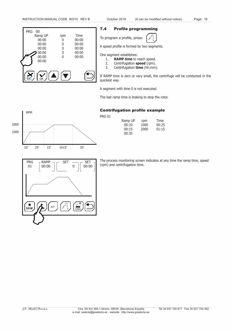
7.4 Profile programming
To program a profile, press:
A speed profile is formed by two segments.
One segment establishes: 1. RAMP time to reach speed. 2. Centrifugation speed (rpm). 3. Centrifugation time (hh:mm).
If RAMP time is zero or very small, the centrifuge will be conducted in the quickest way.
A segment with time 0 is not executed.
The last ramp time is braking to stop the rotor.
Centrifugation profile example
The process monitoring screen indicates at any time the ramp time, speed (rpm) and centrifugation time.
PRG 01 Ramp UP rpm Time 00:10 1000 00:25 00:15 2000 01:15 00:35
PRG 00Ramp UP rpm Time 00:00 0 00:00 00:00 0 00:00 00:00 0 00:00 00:00 0 00:00 00:00 0 00:00 00:00
10’ 25’ 15’ 1h15’ 35’
1000
RPM
2000
RCFOPEN
PRG01
RAMP00:00
SET 0
SET00:00