Embed Size (px)
Citation preview
Rosenberg USA
1010 Forsyth Avenue
Indian Trail, NC 28079
Ph: (704)893-0883
Fax: (704)882-0775
www.rosenbergusa.com
Please contact us:
C e n t r i f u g a l F a n s
w i t h f o r w a r d c u r v e d i m p e l l e r s
ECOFIT
ETRI
T H E A I R M O V E M E N T G R O U P
ECOFIT
ETRI
T H E A I R M O V E M E N T G R O U P
s i n g l e i n l e t / d o u b l e i n l e t
ROSENBERG FANS CANADA Ltd.
125 Traders Blvd. East, Unit#9
Mississauga, ON
L4Z 2H3 Canada
Ph. 905-502-0326
Fax. 905-502-0145
ROSENBERG USA
1010 Forsyth Avenue
Indian Trail, NC 28079
Ph. 704-893-0883
Fax. 704-882-0755

CentrifugalFans CentrifugalFans
withforwardcurvedimpellers withforwardcurvedimpellers

ROSENBERG - ECOFIT - ETRI - THE AIR MOVEMENT GROUP
Serving North America with the highest quality
andMOTORIZED IMPELLERS, FANS BLOWERS
We are proud to be a part of the ROSENBERG family of companies:
Our family of companies is supported by over 1.400 employees with state-of-the art R&D and manufac-
turing throughout the world. Rosenberg USA, with offices and warehouse in Indian Trail, NC, is uniquely
qualified to service all your air handling applications:
• Technical Expertise & Application Engineering
• Outstanding Customer Service
• Design Flexibility & Custom Fan/Motor Equipment
• Stock Fans for Immediate Shipment
• Full Line of Accessory Products & Controls
• Value Added Manufacturing & Fabrication
ROSENBERG - ECOFIT - ETRI - THE AIR MOVEMENT GROUP
Radial Fans
Axial Fans
Duct Fans
Roof fans
Axial Fans for cooling
Switches and Controllers
Rosenberg Ventilatoren GmbH (Kunzelsau, Germany) ECOFIT / ETRI S.A. (Vendome, France)
Edition 07/2007 - Rosenberg reserves the right to make engineering changes without notice
Rosenberg series Reference Code 2
ECOFIT series Reference Code 3
Technical description
Casing 4
Impeller 4
Direction of Rotation 4
Motors 4
Motor Protection 4
Electrical Connection 5
Voltage Types 5
Speed Control 5
Protection against accidental contact 5
Information on safety of machinery 6
Advantages 6
Air performance curves 6
Noise levels 7
ECOFIT series description 8
Description of Performance Curve 60 Hz 9
Performance curves 60 Hz and Dimensions
GRE / GDS / GDF (ECOFIT) 10
DRAE/D (casing with outlet flange) 20
DRAE/D (compact casing) 50
Wiring Diagrams 67

E D
Rosenberg Reference Code
Current
D = double inlet
E = single inlet
R = centrifugal fan
A = external rotor motor
E = single phase A.C.
D = three phase A.C.
Impeller diameter
355 = 355mm (14 inches)
Number of poles
L = Larger casing width
D R A E 251 - 4 L
Characteristics and Construction
The high efficient centrifugal fans have been specially developed for modern ventilation and air conditioning
applications and are ideal for the movement of air and non-aggressive gas and vapours.
They are mainly used in air handling units, hygienic units, clean room filter units.
They find further application in the cooling of electrical motors and generators (e.g. in wind parks), ventilation of switch
cabinets, air conditioning (e.g. in trains).
A high power density with a very compact design is provided by the combination of forward curved wheel and external
rotor motor.
The following design models are available:
• ERAE/D: single inlet centrifugal fan
• DRAE/D: double inlet centrifugal fan
DRAE/DERAE/D
compact casing
(single inlet on request) casing with outlet flange compact casing casing with outlet flange

ECOFIT Reference Code
Number of poles
Type of impeller
Class F standard UL
Stator
Impeller
Rotation direction
Part number
2 GRE u B3 108x52 R F07-A7
GDS / GDFTRE / GRE / GRF
Presentation
The range presented in this catalogue consists of single inlet centrifugal impellers (TRE), single inlet centrifugal fans in
steel scroll (GRE - GRF) and double inlet centrifugal fans (GDS - GDF).
In response to your specific needs, the airflow, power, rotational speeds (multispeed by windings or by controllers),
noise level, overall dimensions and finish... of the fans can be specifically defined according to your requirements. Try
out and appreciate our responsiveness . Consult us right from the beginning of your design.
GDSGRETRE

The casings of the high efficiency centrifugal fans are made of galvanized sheet metal.
The side parts are produced with nut sets to fix the mounting brackets, which can be
fixed in steps of 90°.
Epoxy coating on request.
: steel painted black or plastic scroll.
: galvanised steel or plastic impeller.
Caution: Low air volume at wrong direction of spin!
: direction of rotation is indicated in the catalogue on each datasheet.
: ball bearings closed on both sides are used.
ECOFIT series
The impellers with 38-42 forward curved blades are made of galvanized sheet metal.
They are mounted directly to the external rotor motor.
ECOFIT series
The impellers are statically and dynamically balanced together with the external rotor
motor according to quality level G2,5 DIN ISO 1940.
Direction of rotation for fan types ERA is clockwise viewed from the inlet side, but for fan
types DRA it is anti- clockwise viewed from the cable outlet
ECOFIT series
Rosenberg external rotor motors are manufactured in protection class IP54.
ECOFIT external rotor motors are manufactured in protection class IP44 or IP54 for
GDF.
The winding insulation corresponds to insulation Class F (UL - approved).
Bearings are deep groove ball type in sealed housing. Special grease lubrication
provides maintenance-free operation, low-noise and extended life.
ECOFIT series Special grease lubrication
provides maintenance-free operation, low-noise and extended life.
All motors are equipped with thermal contacts, wired in series. Thermal contacts are
temperature dependent control elements, sensing the winding temperature of the
motor These contacts protect the motor windings from overload, failure of a mains
phase, standstill of the motor and of high temperature rise to the medium ventilated.
In addition to the mounted thermal contacts we recommend the use of our motor
protection control units.
Rosenberg also offers 5-step speed controllers, RTE and RTD.
Motors are equipped with the motor protection in connection with thermal contacts. An
additional motor protection switch is not required.
.
Casings
Direction of rotation
Impellers
Motors
Motor protection

The nominal voltage given on the nameplate provides maximum allowable voltage
tolerance of ± 10%. Flying leads are standard.
The connection ends are 10 cm (4 inches) dismantled and equipped with end splices.
Standard cable length is 68 cm (27 inches)
Special cable lengths are available on request.
ECOFIT motors : refer to drawings.
For single phase operation, motors are available for 115V, 208/230V and 277V.
All 230V motors could also be used at 1~230V, 50Hz.
For three phase operation, motors are available for 208V / 230VD // 460V Y.
575V and other special voltages are available on request.
Please reference 60Hz-curves:
- Standard three phase motor can be used at 460V (Star connection) and 230V (Delta
connection). In Delta connection the motors are also suitable for 208V 3~ power
supplies).
- The performance curves show that the 230VD performance is a little less than the
460VY performance.
The standard three phase motors could also be used at 400V Y, 50Hz.
ECOFIT series
Speed control can be provided for fans that demand optimal adjustment of the
operation point. Speed control is obtained by “Voltage Control” and “Frequency
Control”, as described below.
The speed control is provided by reduction of the terminal voltage. If the voltage will
be reduced the speed of the motor decreases and the air volume flow sinks in
proportion with the speed. The matching voltage controllers can be provided on
request.
All voltage controllable fans for three-phase power supplies can also be speed
controlled by frequency converter from 60Hz downwards. The speed control is
realized by reduction of the power supply frequency. At higher frequencies than 60Hz
the motor will be thermally overloaded.
With operation of the motors on a frequency controller the maximum speed of
voltage increase of 500V /μs must not be exceeded. According to the frequency
converter type and the length of the cable between motor and frequency converter
additional components must be planned. Please refer to the operation manual of the
frequency converter.
The fans are constructed for installation within applications. We do not include
guards of any kind as a part of our standard product offering. Please contact your
Rosenberg representative for accessory information.
Before initial operation all required protection components must be installed and
connected. Adherence to all electrical and safety codes, including National Electric
Codes (NEC), National Fire Protection Association (NFPA) standards and Occupational
Safety and Health Act (OSHA) should be followed and are responsibility of the customer.
All electrical connections should be performed only by qualified personnel.
: for single phase operation, motors are available for 115V, 60Hz. Most
of them are usable on 50Hz (refer to drawings).
Voltage control
Frequency control
Electrical connection
Voltages types
Speed control
Protection against
accidental contact

Rosenberg radial fans are usable machines according to the EC Council Directive on
Machinery. They are marked with a CE label and delivered with a declaration of
conformity.
The dangers of the fan as well as necessary technical measures of safety are judged
according to the VDMA standard sheet number 24167: Fans, demands of safety.
The operation manual contains additional measures of safety to be realized on site to
make the fan match the EC Council Directive on Machinery 98/37/EC.
Information on safetyof machinery
Advantages of Rosenberg high efficient centrifugal fans:
• Compact and space saving design with external rotor motor drive and high
performance forward curved impeller
• Low for maintenance direct drive fans (no belt wear or belt replacement necessary)
• Various control possibilities
• Customers requirements can be met without problems
• Easy installation in any position
• Extremely low starting currents
• Motor protection through thermal contacts in motor winding
Air Performance Curves
The air performance curves have been established using the inlet test method in the test chamber as shown below
according to German standard DIN 24163. They are valid for air with a density with a temperature of
68°F. The performance curves were made in mounting position A (free inlet, free outlet) and show the pressure
increase, available on inlet side, pfa as a function of the volume.
of 0.075#/ft³
3 Throttling device with straightener
4 Screens5 Straightener6 Measuring chamber with shutters
7 Inlet cone pressure manometer (pd)
8 Pressure manometer pfa
Test chamber
1 Inlet cone2 Transition parts
6

Noise levels
The tests and their performance curves were made according to DIN 45635, part 38, according to the envelope surface
method, after collection several test points by a cube shaped test area.
1 shutter door
2 sound attenuator
3 test sample
4 measurement
arrangement
5 acoustic measuring
room with reflecting floor
The characteristic diagram shows the “A” decibel Sound Power level L ,. This corresponds to the free-outlet W(A)
sound power level L .W(A)6
The free inlet sound power level L can be obtained by the relative sound power level or according to following W(A)5
calculation:
L = L - 3 dB(A)W(A)5 W(A)
For the exact determination of the sound protection measures the sound power level of the octave bands are
important.
L = L + LWoct W(A) wrel
DRAE ; DRAD
ERAE ; ERAD
WA A-weighted at V = 0,5 * Vrel max
WA A-weighted at V = 0,5 * Vrel max
125
125
250
250
500
500
1000
1000
2000
2000
4000
4000
8000
8000
Hz
Hz
dB
dB
dB
dB
The expected sound pressure level on the outlet side can
only be approximately determined as the ambient
influences can lead to strong deviations.
L = L - D LP(A) W(A)
a= without reflections
b= with reflections
L
Outlet side 4-pole
Outlet side 4-pole
Inlet side 4-pole
Inlet side 4-pole
fM [Hz]
fM [Hz]
-21
-23
-13
-10
-8
-8
-4
-4
-7
-7
-8
-9
-15
-16
-18
-19
-13
-11
-10
-11
-5
-5
-4
-5
-10
-8
-16
-14
L
L
7

ECOFIT series
Conditions of use
Centrifugal fans with forward-curved impeller blades demand maximum motor power at maximum air flow rate and zero
static pressure. Certain fan models have minimum pressure levels below which their motors will over-heat.
Performance curves then terminate at minimum permitted pressure.
Impellers with forward-curved blades must be used with the scroll housing and inlet ring recommended by ECOFIT in order to obtain the performance levels declared within this catalogue. Modifications to scroll or inlet will affect fan performance. If the scroll and inlet are part of an appliance, they must be of the same shape and size as the ECOFIT standard, or otherwise approved by ECOFIT.
Inlet rings and finger guards are available upon request.
ECOFIT motors are speed controllable by voltage variation, but where electronic controllers are used they must be designed for electric motor duty and be compatible with ECOFIT products.
Capacitors must be of the "motor run" type and be of the recommended value, voltage rating, and life expectancy.
The purchaser must test for motor total temperature in the application, with the worst operating conditions for the motor. ECOFIT should then validate the test results.
Noise level
The tabulated overall sound levels are to NF S31-026 standard and are expressed as 'A' weighted acoustic pressure, measured one meter from the air inlet.
Life expectancy
The ECOFIT motors and fans described in this catalogue are fifted with ball bearings for use in any mounting attitude. L10 life expectancy is between 30000 and 50000 hours, depending on the application and ambient condition.
0
Pa
m³/h 0
Wa
m³/h 0
rpm
m³/h
L
ØdL = 0,63 x Ødmin.
GDS / GDFTRE / GRE / GRF
L
ØdL = 0,63 x Ødmin.
L
8

TypeU
[Volt]
f
[Hz] CurveP1
[kW]
IN
[A]
n-1
[min ]
tR
[°C]C
[μF] [%]I /IA N [kg]
tR
[°F]
DRAE 181-4
DRAE 181-4
DRAE 181-4
1~115
1~230
1~230
60
60
50
A
A
B
0.23 2.10 960 158 70 16 - 1.1 54 01.025 10
0.23 1.05 960 158 70 4 - 1.1 54 01.025 10
0.20 0.90 1060 158 70 4 - 1.5 54 01.025 9.7
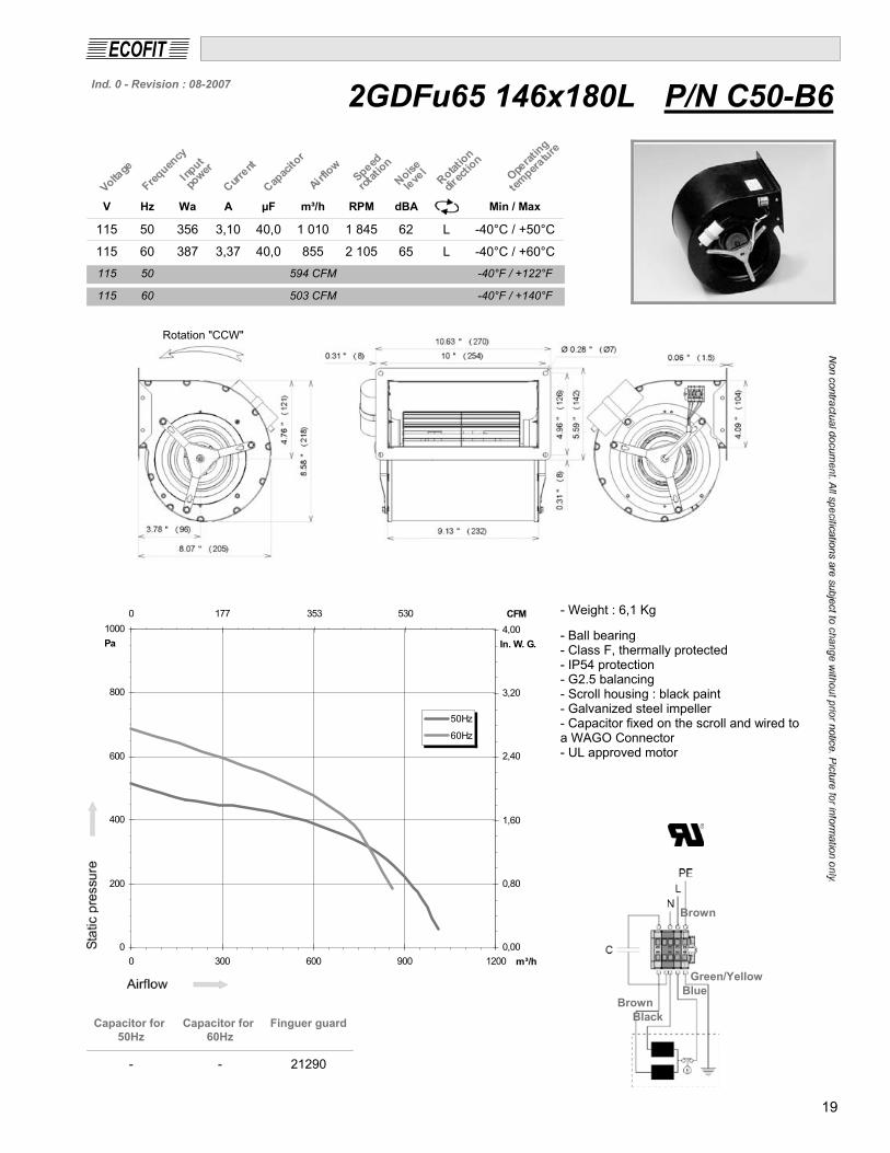
Performance Curves
The performance curves indicate the static pressure increase Dpfa as a function of the volume flow. The performance
curves refer to an air density of 0.075 kg/ft³.
Fan performance curve at
rated voltage 60Hz:
Single phase motors:
Curve A=rated voltage
(115 V or 230 V ; depends
on motor execution)
Three phase motors:
Curve A=460 V Y-connection
Curve B=230 V D-connection
Fan performance curve at
rated voltage 50 Hz
Information:
Every three phase motor can be used at 460 V (Star connection) and 230 V (Delta connection).
The performance curves show that the 230VD (curve B) performance is a little less than
the 460VY (curve A)performance. In Delta connection the motors are also suitable for 208V
3~ power supplies.
Technical Information
Designation Unit
U Rated voltage V
P Motor input power consumption kW1
I Rated current AN
-1n Fan speed min
tR Max. permissible medium temperature °C / °F
L A-rated sound power level dB(A)W(A)
DI Current increase in component voltage %
I /I Ratio of starting current to rated current -A N
IP protection class
Wiring diagram
Weight
Information of the dimensions in inch and mm!
Sound power levelA
BC 90
93
90
91
89
90
DRAD 356-4 IP10
9

10
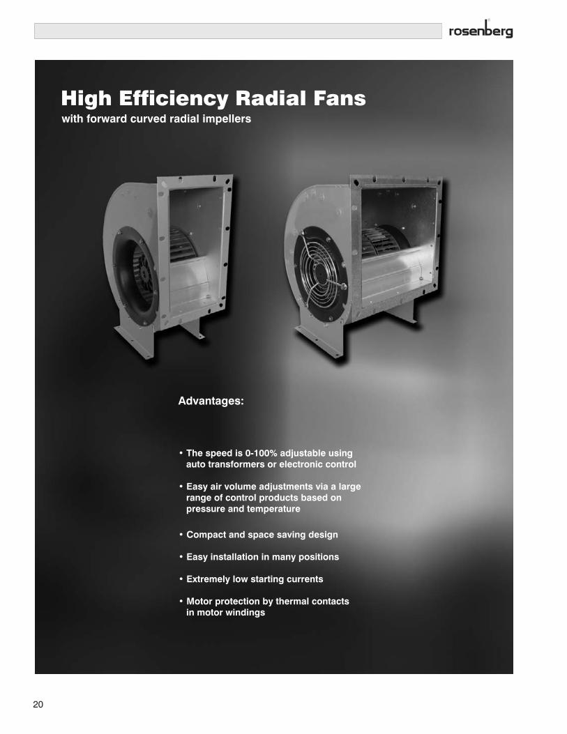
High Efficiency Radial Fanswith forward curved radial impellers
Advantages:
• The speed is 0-100% adjustable using auto transformers or electronic control
• Easy air volume adjustments via a large range of control products based on pressure and temperature
• Compact and space saving design
• Easy installation in many positions
• Extremely low starting currents
• Motor protection by thermal contacts in motor windings

11

12

13

14

15

16

17

18
19
High Efficiency Radial Fanswith forward curved radial impellers
Advantages:
• The speed is 0-100% adjustable using
auto transformers or electronic control
• Easy air volume adjustments via a large
range of control products based on
pressure and temperature
• Compact and space saving design
• Easy installation in many positions
• Extremely low starting currents
• Motor protection by thermal contacts
in motor windings
20
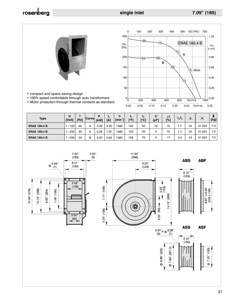
7.09” (180)single inlet
TypeU
[Volt]
f
[Hz] CurveP
[kW]1
I
[A]N
n
[min ]-1
t
[°C]R C
[μF] [%]I /IA N [kg]
t
[°F]R
ERAE 180-4 B
ERAE 180-4 B
ERAE 180-4 B
1~120
1~230
1~230
60
60
50
A
A
B
• compact and space saving design
• 100% speed controllable through auto transformers
• Motor protection through thermal contacts as standard
0.29 2.50 1480 122 50 16 15 1.7 54 01.024 7.0
0.29 1.25 1480 122 50 4 15 1.7 54 01.024 7.0
0.20 0.93 1365 158 70 4 17 2.5 54 01.024 7.0
21
ERAE 180-4 B
dB(A)
A
B
75
73
6870
72
64 66
69
p
[Pa]fa

7.87” (200)
TypeU
[Volt]
f
[Hz] CurveP
[kW]1
I
[A]N
n
[min ]-1
t
[°C]R C
[μF] [%]I /IA N [kg]
t
[°F]R
ERAE 200-4 B
ERAE 200-4 B
ERAE 200-4 B
1~120
1~230
1~230
60
60
50
A
A
B
0.40
0.40
1.75
3.50
1340
1340
122
122
50
50
10
24
2.0
2.0
1.3
1.3
54
54
01.024
01.024
8
8
0.35 1.60 1180 122 50 10 2.0 1.6 54 01.024 8
22
• compact and space saving design
• 100% speed controllable through auto transformers
• Motor protection through thermal contacts as standard
single inlet
ERAE 200-4 B
dB(A)
A
B
79
76
7173
75
6769
72
p
[Pa]fa

8.86” (225)
ERAE 225-4 50 B 0.47 2.40 1350 140 60 8 17 2.6 54 01.024 12
ERAE 225-4 60 A 0.55 1.8 54 01.0242.60 1570 122 50 8 8 12
ERAE 225-4 60 A 0.55 5.20 1570 122 50 30 8 1.8 54 01.024 12
P
[kW]1
I
[A]N
t
[°C]R C
[μF]
t
[°F]R
TypeU
[Volt]
f
[Hz] Curven
[min ]-1
[%]I /IA N [kg]
1~120
1~230
1~230
23
• compact and space saving design
• 100% speed controllable through auto transformers
• Motor protection through thermal contacts as standard
single inlet
ERAE 225-4
dB(A)
A
B 83
79
75 77
79
71 73
75
p
[Pa]fa

9.84” (250)
TypeU
[Volt]
f
[Hz] CurveP
[kW]1
I
[A]N
n
[min ]-1
t
[°C]R C
[μF] [%]I /IA N [kg]
t
[°F]R
ERAE 250-4
ERAE 250-4
ERAE 250-4
1~120
1~230
1~230
60
60
50
A
A
B
0.99 8.60 1320 122 50 64 - 1.5 54 01.024 17.5
0.99
0.77
4.30
3.50
1320
1300
122
149
50
65
16
16
-
-
1.5
1.7
54
54
01.024
01.024
17.5
17.5
24
• compact and space saving design
• 100% speed controllable through auto transformers
• Motor protection through thermal contacts as standard
single inlet
ERAE 250-4
dB(A)
A
B 84
82
7777
80
7375
78
p
[Pa]fa

9.84” (250)
TypeU
[Volt]
f
[Hz] CurveP
[kW]1
I
[A]N
n
[min ]-1
t
[°C]R C
[μF] [%]I /IA N [kg]
t
[°F]R
ERAD 250-4
ERAD 250-4
ERAD 250-4
60
60
50
A
B
C
1.15 1.90 1400 122 50 - - 2.6 54 01.005 18
1.00 3.10 1325 140 60 - - 2.6 54 01.006 18
0.75 1.60 1230 149 65 - - 3.6 54 01.005 183~400Y
3~230D
3~460Y
25
• compact and space saving design
• 100% speed controllable through auto transformers
• Motor protection through thermal contacts as standard
single inlet
ERAD 250-4
dB(A)
A
B
C83
84
77 78
81
78
80
82
7375
78
p
[Pa]fa

9.84” (250)
TypeU
[Volt]
f
[Hz] CurveP
[kW]1
I
[A]N
n
[min ]-1
t
[°C]R C
[μF] [%]I /IA N [kg]
t
[°F]R
ERAE 250-6
ERAE 250-6
ERAE 250-6
60
60
50
A
A
B
0.35 3.10 720 122 50 24 - 1.1 54 01.024 15
0.35 1.55 720 6 - 1.1 54 01.024 15
0.30 1.30 760 140
122
60
50
6 - 1.4 54 01.024 15
1~120
1~230
1~230
26
• compact and space saving design
• 100% speed controllable through auto transformers
• Motor protection through thermal contacts as standard
single inlet
ERAE 250-6
dB(A)
A
B
68 69
75
72
69
65 66
72
p
[Pa]fa

9.84” (250)
TypeU
[Volt]
f
[Hz] CurveP
[kW]1
I
[A]N
n
[min ]-1
t
[°C]R C
[μF] [%]I /IA N [kg]
t
[°F]R
ERAD 250-6
ERAD 250-6
ERAD 250-6
60
60
50
A
B
C
0.40 0.75 990 122 50 - - 1.9 54 01.005 15
0.35 1.20 930 140 60 - - 1.9 54 01.006 15
0.33 0.70 820 122 50 - - 2.1 54 01.005 153~400Y
3~230D
3~460Y
27
• compact and space saving design
• 100% speed controllable through auto transformers
• Motor protection through thermal contacts as standard
single inlet
ERAD 250-6
dB(A)
A
B
C74
75
686968
68
82
82
7375
71
72
p
[Pa]fa
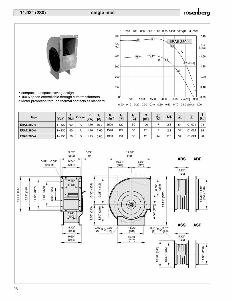
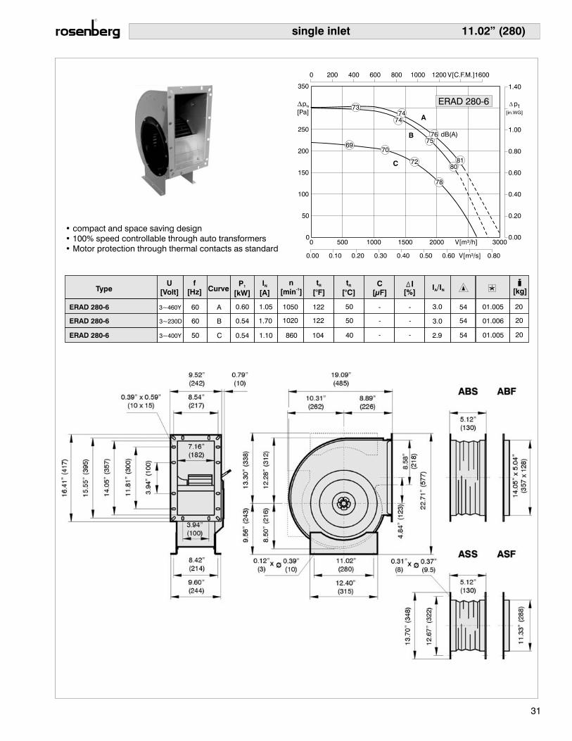
11.02” (280)
TypeU
[Volt]
f
[Hz] CurveP
[kW]1
I
[A]N
n
[min ]-1
t
[°C]R C
[μF] [%]I /IA N [kg]
t
[°F]R
ERAE 280-4
ERAE 280-4
ERAE 280-4
60
60
50
A
A
B
1.70 15.2 1520 122 50 100 7 2.1 54 01.024 28
1.70 7.60 1520 122 50 25 7 2.1 54 01.024 28
1.45 6.80 1330 131 55 25 14 2.5 54 01.024 28
1~120
1~230
1~230
28
• compact and space saving design
• 100% speed controllable through auto transformers
• Motor protection through thermal contacts as standard
single inlet
ERAE 280-4
dB(A)
A
B
6869
68
82
82
7375
72
p
[Pa]fa

TypeU
[Volt]
f
[Hz] CurveP
[kW]1
I
[A]N
n
[min ]-1
t
[°C]R C
[μF] [%]I /IA N [kg]
t
[°F]R
ERAD 280-4
ERAD 280-4
ERAD 280-4
60
60
50
A
B
C
2.05 3.20 1585 122 50 - 4 3.0 54 01.005 24
1.90 5.50 1490 122 50 - 3 3.0 54 01.006 24
1.55 2.90 1310 122 50 - 6 3.9 54 01.005 24
11.02” (280)
3~400Y
3~230D
3~460Y
29
• compact and space saving design
• 100% speed controllable through auto transformers
• Motor protection through thermal contacts as standard
single inlet
ERAD 280-4
dB(A)
A
B
C
90
82 83
8079
82
85
8986
p
[Pa]fa

TypeU
[Volt]
f
[Hz] CurveP
[kW]1
I
[A]N
n
[min ]-1
t
[°C]R C
[μF] [%]I /IA N [kg]
t
[°F]R
ERAE 280-6
ERAE 280-6
ERAE 280-6
60
60
50
A
A
B
0.67 3.00 1030 122 50 10 7 1.9 54 01.024 20
0.67 6.00 1030 122 50 40 7 1.9 54 01.024 20
0.60 2.90 880 122 50 10 14 2.2 54 01.024 20
11.02” (280)
1~120
1~230
1~230
30
• compact and space saving design
• 100% speed controllable through auto transformers
• Motor protection through thermal contacts as standard
single inlet
ERAE 280-6
dB(A)
A
B80
73 74
7069
72
76
76
p
[Pa]fa
11.02” (280)
TypeU
[Volt]
f
[Hz] CurveP
[kW]1
I
[A]N
n
[min ]-1
t
[°C]R C
[μF] [%]I /IA N [kg]
t
[°F]R
ERAD 280-6
ERAD 280-6
ERAD 280-6
60
60
50
A
B
C
0.60 1.05 1050 122 50 - - 3.0 54 01.005 20
0.54 1.70 1020 122 50 - - 3.0 54 01.006 20
0.54 1.10 860 104 40 - - 2.9 54 01.005 203~400Y
3~230D
3~460Y
31
• compact and space saving design
• 100% speed controllable through auto transformers
• Motor protection through thermal contacts as standard
single inlet
ERAD 280-6
dB(A)
A
B
C 8081
7374
74
72
78
7069
7576
p
[Pa]fa

TypeU
[Volt]
f
[Hz] CurveP
[kW]1
I
[A]N
n
[min ]-1
t
[°C]R C
[μF] [%]I /IA N [kg]
t
[°F]R
ERAE 315-6
ERAE 315-6
ERAE 315-6
60
60
50
A
A
B
1.15 5.60 835 140 60 64 - 1.4 54 01.025 32
1.15 11.2 835 140 60 16 - 1.4 54 01.025 32
0.96 5.30 804 158 70 16 - 1.6 54 01.025 32
12.40” (315)
1~120
1~230
1~230
32
• compact and space saving design
• 100% speed controllable through auto transformers
• Motor protection through thermal contacts as standard
single inlet
ERAE 315-6
dB(A)
A
B
78
80
79
??
??
????82
p
[Pa]fa

TypeU
[Volt]
f
[Hz] CurveP
[kW]1
I
[A]N
n
[min ]-1
t
[°C]R C
[μF] [%]I /IA N [kg]
t
[°F]R
ERAD 315-6
ERAD 315-6
ERAD 315-6
60
60
50
A
B
C
1.20 2.1 1025 122 50 - - 2.7 54 01.005 27
1.10 3.5 980 122 50 - - 2.7 54 01.006 27
0.95 2.1 850 122 50 - - 2.5 54 01.005 27
12.40” (315)
3~400Y
3~230D
3~460Y
33
• compact and space saving design
• 100% speed controllable through auto transformers
• Motor protection through thermal contacts as standard
single inlet
ERAD 315-6
dB(A)
AB
C85
86
79 80
78
82
7675
8182
p
[Pa]fa

TypeU
[Volt]
f
[Hz] CurveP
[kW]1
I
[A]N
n
[min ]-1
t
[°C]R C
[μF] [%]I /IA N [kg]
t
[°F]R
ERAD 315-4
ERAD 315-4
ERAD 315-4
60
60
50
A
B
C
2.90 4.90 1635 122 50 - 9 4.8 54 01.005 36
2.75 8.30 1590 122 50 - 9 4.8 54 01.006 36
2.05 4.40 1380 158 70 - 5 4.2 54 01.005 36
12.40” (315)
3~400Y
3~230D
3~460Y
34
• compact and space saving design
• 100% speed controllable through auto transformers
• Motor protection through thermal contacts as standard
single inlet
ERAD 315-4
dB(A)
AB
C
9091
84 85
83
87
8180
8787
p
[Pa]fa

TypeU
[Volt]
f
[Hz] CurveP
[kW]1
I
[A]N
n
[min ]-1
t
[°C]R C
[μF] [%]I /IA N [kg]
t
[°F]R
ERAD 355-6
ERAD 355-6
ERAD 355-6
60
60
50
A
B
C
1.70 2.8 960 122 50 - - 2.5 54 01.005 35
1.50 4.7 880 122 50 - - 2.5 54 01.006 35
1.50 2.75 760 104 40 - - 2.6 54 01.005 35
13.98” (355)
3~400Y
3~230D
3~460Y
35
• compact and space saving design
• 100% speed controllable through auto transformers
• Motor protection through thermal contacts as standard
single inlet
ERAD 355-6
dB(A)
A
B
C 83
85
78 80
79
80
84
7775 82
83
p
[Pa]fa

TypeU
[Volt]
f
[Hz] CurveP
[kW]1
I
[A]N
n
[min ]-1
t
[°C]R C
[μF] [%]I /IA N [kg]
t
[°F]R
ERAD 400-6
ERAD 400-6
ERAD 400-6
60
60
50
A
B
C
3.50 5.45 1040 104 40 - - 3.1 54 01.005 64
3.20 9.70 970 104 40 - - 3.1 54 01.006 64
3.00 5.50 860 104 40 - - 3.1 54 01.005 64
15.75” (400) single inlet
3~400Y
3~230D
3~460Y
36
• compact and space saving design
• 100% speed controllable through auto transformers
• Motor protection through thermal contacts as standard
ERAD 400-6
dB(A)
A
B
C
82888187
85
90
8178
8788
p
[Pa]fa

7.09” (180)double inlet
TypeU
[Volt]
f
[Hz] CurveP
[kW]1
I
[A]N
n
[min ]-1
t
[°C]R C
[μF] [%]I /IA N [kg]
t
[°F]R
DRAE 180-4 B
DRAE 180-4 B
DRAE 180-4 B
1~120
1~230
1~230
60
60
50
A
A
B
0 500 1000 1500 V[m /h]2
2500
0.00 0.10 0.20 0.30 0.40 0.50 V[m /s]2
0.70
0 200 400 600 800 1000 1200 V[C.F.M.]
0
50
100
150
200
250
350
0.00
0.20
0.40
0.60
0.80
1.00
1.40
dB(A)
DRAE 180-4 B[in.WG]
pt
A
B 75
71
68
73
0.46 4.00 1420 122 50 24 - 1.8 54 01.025 9.5
0.46 2.00 1420 122 50 6 - 1.8 54 01.025 9.5
0.42 1.90 1250 122 50 6 21 2.0 54 01.025 9.5
37
• compact and space saving design
• 100% speed controllable through auto transformers
• Motor protection through thermal contacts as standard
p
[Pa]fa

7.87” (200) double inlet
TypeU
[Volt]
f
[Hz] CurveP
[kW]1
I
[A]N
n
[min ]-1
t
[°C]R C
[μF] [%]I /IA N [kg]
t
[°F]R
DRAE 200-4 B
DRAE 200-4 B
DRAE 200-4 B
1~120
1~230
1~230
60
60
50
A
A
B
DRAE 200-4 B
0.62
0.62
2.70
5.40
1350
1350
122
122
50
50
10
40
-
-
1.5
1.5
54
54
01.025
01.025
13
13
0.52 2.30 1250 122 50 10 2.0 1.8 54 01.025 13
dB(A)
A
B
76
75
7473
74
6969
72
38
• compact and space saving design
• 100% speed controllable through auto transformers
• Motor protection through thermal contacts as standard
p
[Pa]fa

7.87” (200)
DRAD 200-4 B 3~400Y 50 C 0.56 0.98 1170 104 40 - - 2.4 54 01.005 11
DRAD 200-4 B 3~230D 60 B 0.57 2.3 54 01.0061.65 1400 104 40 - - 11
DRAD 200-4 B 3~460Y 60 A 0.62 0.98 1470 104 40 - - 2.3 54 01.005 11
P
[kW]1
I
[A]N
t
[°C]R C
[μF]
t
[°F]R
TypeU
[Volt]
f
[Hz] Curven
[min ]-1
[%]I /IA N [kg]
75
7276
C
6870
7474B
A74
7475
75 DRAD 200-4 B
39
• compact and space saving design
• 100% speed controllable through auto transformers
• Motor protection through thermal contacts as standard
double inlet
p
[Pa]fa

8.82” (224)
TypeU
[Volt]
f
[Hz] CurveP
[kW]1
I
[A]N
n
[min ]-1
t
[°C]R C
[μF] [%]I /IA N [kg]
t
[°F]R
DRAE 224 B (IP10)-4
DRAE 224 B (IP10)-4
DRAE 224 B (IP10)-4
1~120
1~230
1~230
60
60
50
A
A
B
0.68 5.80 1200 122 50 40 - 1.5 54 01.025 13.5
0.68
0.57
2.90
2.50
1200
1250
122
122
50
50
10
10
-
2
1.5
1.8
54
54
01.025
01.025
13.5
13.5
DRAE 224-4 B IP10
dB(A)
A
B
77
78
76
76
74 73
73
74
40
• compact and space saving design
• 100% speed controllable through auto transformers
• Motor protection through thermal contacts as standard
double inlet
p
[Pa]fa

8.82” (224)
TypeU
[Volt]
f
[Hz] CurveP
[kW]1
I
[A]N
n
[min ]-1
t
[°C]R C
[μF] [%]I /IA N [kg]
t
[°F]R
DRAE 224-4 B (5LA)
DRAE 224-4 B (5LA)
DRAE 224-4 B (5LA)
1~115
1~230
1~230
60
60
50
A
A
B
1.30 11 1240 104 40 50 - 1.6 54 01.025 16
1.30 5.50 1240 104 40 14 - 1.6 54 01.025 16
1.10 4.70 1140 140 60 14 20 1.8 54 01.025 16
dB(A)
A
B
DRAE 224-4 B (5LA)77
77
73 81
78
76
7374
41
• compact and space saving design
• 100% speed controllable through auto transformers
• Motor protection through thermal contacts as standard
double inlet
p
[Pa]fa

8.82” (224)
TypeU
[Volt]
f
[Hz] CurveP
[kW]1
I
[A]N
n
[min ]-1
t
[°C]R C
[μF] [%]I /IA N [kg]
t
[°F]R
DRAD 224-4 B
DRAD 224-4 B
DRAD 224-4 B
60
60
50
A
B
C
0.92 1.45 1515 104 40 - - 2.6 54 01.005 14
0.83 2.45 1380 - - 2.6 54 01.006 14
0.87 1.50 1210 104
104
40
40
- - 2.5 54 01.005 14
DRAD 224-4 B77
75
76
80
A
B
C
78
77
7473
73
75
76
3~400Y
3~230D
3~460Y
42
• compact and space saving design
• 100% speed controllable through auto transformers
• Motor protection through thermal contacts as standard
double inlet
p
[Pa]fa

9.84” (250)
TypeU
[Volt]
f
[Hz] CurveP
[kW]1
I
[A]N
n
[min ]-1
t
[°C]R C
[μF] [%]I /IA N [kg]
t
[°F]R
DRAD 250-4 IP54
DRAD 250-4 IP54
DRAD 250-4 IP54
60
60
50
A
B
C
1.50 2.60 1550 122 50 - - 2.9 54 01.005 29
1.40 2.40 1480 122 50 - - 2.9 54 01.006 29
1.60 2.95 1200 140 60 - - 2.5 54 01.005 29
DRAD 250-4 IP54
85
89
A
B
C
88
82
86
85
3~400Y
3~230D
3~460Y
43
• compact and space saving design
• 100% speed controllable through auto transformers
• Motor protection through thermal contacts as standard
double inlet
p
[Pa]fa

11.02” (280)
TypeU
[Volt]
f
[Hz] CurveP
[kW]1
I
[A]N
n
[min ]-1
t
[°C]R C
[μF] [%]I /IA N [kg]
t
[°F]R
DRAD 280-4
DRAD 280-4
DRAD 280-4
60
60
50
A
B
C
3.20 4.50 1530 122 50 - 13 3.5 54 01.005 40
3.00 8.20 1440 122 50 - 8 3.5 54 01.006 40
2.70 4.30 1250 140 60 - 8 5.0 54 01.005 40
DRAD 280-48687
90
A
B
C
86
87
82
87
89
3~400Y
3~230D
3~460Y
44
• compact and space saving design
• 100% speed controllable through auto transformers
• Motor protection through thermal contacts as standard
double inlet
p
[Pa]fa
TypeU
[Volt]
f
[Hz] CurveP
[kW]1
I
[A]N
n
[min ]-1
t
[°C]R C
[μF] [%]I /IA N [kg]
t
[°F]R
DRAD 315-4
DRAD 315-4
DRAD 315-4
60
60
50
A
B
C
6.20 9.70 1630 122 50 - 10 4.5 54 01.005 60
5.80 17.0 1570 122 50 - 8 4.5 54 01.006 60
4.50 8.70 1370 140 60 - - 4.3 54 01.005 60
DRAD 315-49191
93
97
A
B
C
97
91
8787
90
94
91
93
12.40” (315)
3~400Y
3~230D
3~460Y
45
• compact and space saving design
• 100% speed controllable through auto transformers
• Motor protection through thermal contacts as standard
double inlet
p
[Pa]fa

TypeU
[Volt]
f
[Hz] CurveP
[kW]1
I
[A]N
n
[min ]-1
t
[°C]R C
[μF] [%]I /IA N [kg]
t
[°F]R
DRAD 315-6
DRAD 315-6
DRAD 315-6
60
60
50
A
B
C
2.50 3.90 880 122 50 - - 2.2 54 01.005 36.5
2.20 6.80 815 122 50 - - 2.2 54 01.006 36.5
2.10 3.70 780 140 60 - - 2.6 54 01.005 36.5
DRAD 315-6
83
86
AB
C
85
80
84
82
12.40” (315)
3~400Y
3~230D
3~460Y
46
• compact and space saving design
• 100% speed controllable through auto transformers
• Motor protection through thermal contacts as standard
double inlet
p
[Pa]fa
13.98” (355)
TypeU
[Volt]
f
[Hz] CurveP
[kW]1
I
[A]N
n
[min ]-1
t
[°C]R C
[μF] [%]I /IA N [kg]
t
[°F]R
DRAD 355-4
DRAD 355-4
DRAD 355-4
60
60
50
A
B
C
7.65 11.7 1655 104 40 - 24 4.7 54 01.005 79
7.30 21.3 1610 104 40 - 18 4.5 54 01.006 79
6.65 11.8 1365 104 40 - 11 3.7 54 01.005 793~400Y
3~230D
3~460Y
DRAD 355-49594
97
A
B
C
95
91 91
93
99
94
96
47
• compact and space saving design
• 100% speed controllable through auto transformers
• Motor protection through thermal contacts as standard
double inlet
p
[Pa]fa

TypeU
[Volt]
f
[Hz] CurveP
[kW]1
I
[A]N
n
[min ]-1
t
[°C]R C
[μF] [%]I /IA N [kg]
t
[°F]R
DRAD 355-6
DRAD 355-6
DRAD 355-6
60
60
50
A
B
C
3.10 4.70 990 104 40 - 2 3.0 54 01.005 50.5
2.80 8.30 910 104 40 - - 3.0 54 01.006 50.5
2.95 5.20 790 104 40 - - 3.0 54 01.006 50.5
DRAD 355-6
83
86
84
88
A
B
C
86
8586
85
13.98” (355)
3~400Y
3~230D
3~460Y
48
• compact and space saving design
• 100% speed controllable through auto transformers
• Motor protection through thermal contacts as standard
double inlet
p
[Pa]fa

TypeU
[Volt]
f
[Hz] CurveP
[kW]1
I
[A]N
n
[min ]-1
t
[°C]R C
[μF] [%]I /IA N [kg]
t
[°F]R
DRAD 400-6
DRAD 400-6
DRAD 400-6
60
60
50
A
B
C
5.70 9.6 1040 122 50 - 4 3.2 54 01.005 94
5.20 17 990 122 50 - 4 3.2 54 01.006 94
5.30 10 845 104 40 - 3 3.2 54 01.005 94
DRAD 400-689 88
91
92
A
B
C 88
89
8686
88
90
15.75” (400)double inlet
3~400Y
3~230D
3~460Y
49
• compact and space saving design
• 100% speed controllable through auto transformers
• Motor protection through thermal contacts as standard
p
[Pa]fa
Advantages:
• Steep pressure-volume-performance curve
• The speed is 0-100% adjustable using
auto transformers or electronic control
• Easy air volume adjustments via a large
range of control products based on
pressure and temperature
• Compact and space saving design
• Easy installation in many positions
• Extremely low starting currents
• Motor protection by thermal contacts
in motor windings
High Efficiency Radial Fanswith compact casing
50
• Steep pressure-volume-performance curve
• compact and space saving design
• 100% speed controllable through auto transformers
• Motor protection through thermal contacts as standard
TypeU
[Volt]
f
[Hz] CurveP
[kW]1
I
[A]N
n
[min ]-1
t
[°C]R C
[μF] [%]I /IA N [kg]
t
[°F]R
DRAE 181-4
DRAE 181-4
DRAE 181-4
1~120
1~230
1~230
60
60
50
A
A
B
0.23 2.10 960 158 70 16 - 1.1 54 01.025 10
0.23 1.05 960 158 70 4 - 1.1 54 01.025 10
0.20 0.90 1060 158 70 4 - 1.5 54 01.025 10
7.13” (181)double inlet
51
0 200 400 600 800 V[m /h]2
1200
0.00 0.05 0.10 0.15 0.20 0.25 V[m /s]2
0.35
0 100 200 300 400 500 V[C.F.M.] 700
0
50
100
150
200
250
0.00
0.20
0.40
0.60
0.80
1.00
69
69
[in.WG]
pst
DRAE 181-4
A
B
70
67
p
[Pa]fa
TypeU
[Volt]
f
[Hz] CurveP
[kW]1
I
[A]N
n
[min ]-1
t
[°C]R C
[μF] [%]I /IA N [kg]
t
[°F]R
DRAE 195-4
DRAE 195-4
DRAE 195-4
1~120
1~230
1~230
60
60
50
A
A
B
0.32 2.80 880 140 60 20 - 1.1 54 01.025 11.5
0.32 1.40 880 140 60 5 - 1.1 54 01.025 11.5
11.50.28 1.20 950 158 70 5 - 1.4 54 01.025
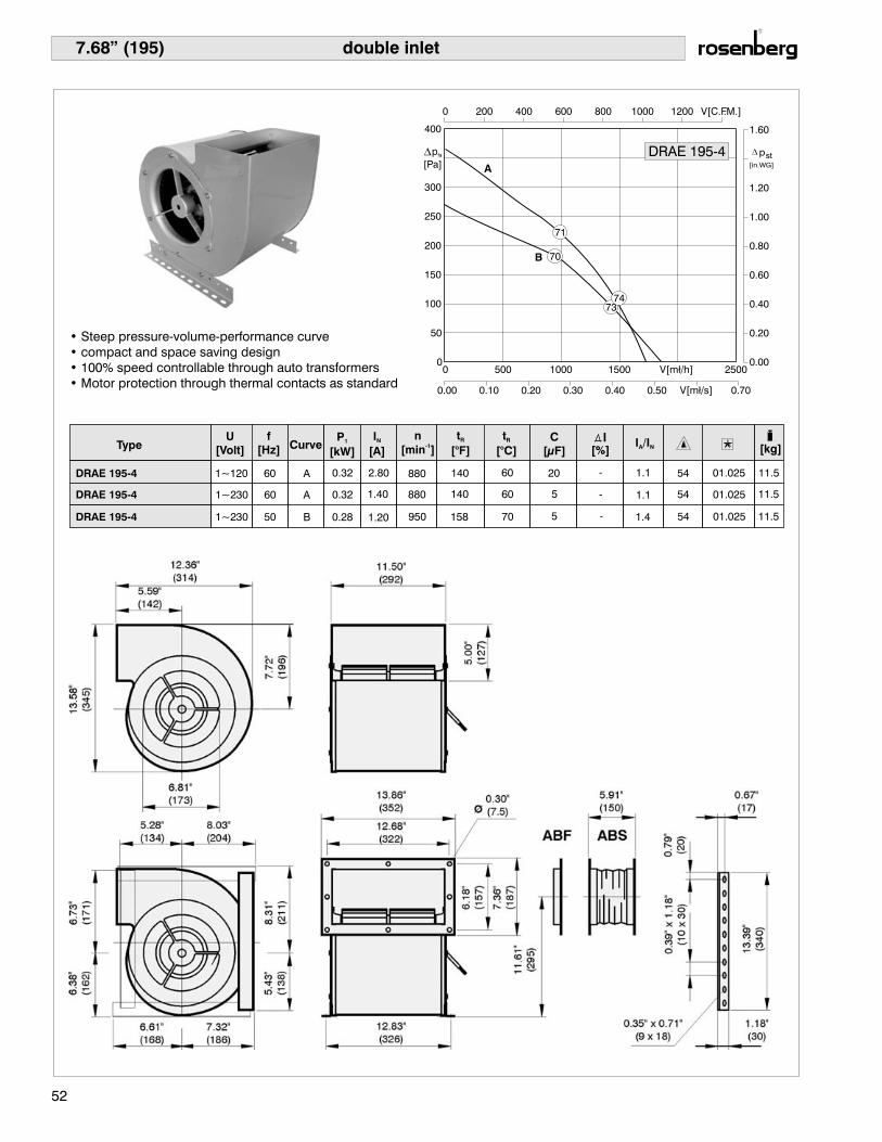
7.68” (195)
52
• Steep pressure-volume-performance curve
• compact and space saving design
• 100% speed controllable through auto transformers
• Motor protection through thermal contacts as standard
double inlet
0 500 1000 1500 V[m³/h] 2500
0.00 0.10 0.20 0.30 0.40 0.50 V[m³/s] 0.70
0 200 400 600 800 1000 1200 V[C.F.M.]
0
50
100
150
200
250
300
400
0.00
0.20
0.40
0.60
0.80
1.00
1.20
1.60
DRAE 195-4A
B 70
71
7374
[in.WG]
pstp
[Pa]fa

TypeU
[Volt]
f
[Hz] CurveP
[kW]1
I
[A]N
n
[min ]-1
t
[°C]R C
[μF] [%]I /IA N [kg]
t
[°F]R
DRAE 195-4L
DRAE 195-4L
DRAE 195-4L
1~120
1~230
1~230
60
60
50
A
A
B
0.51 4.80 1130 122 50 30 - 1.2 54 01.025 13
0.51 2.40 1130 122 50 8 - 1.2 54 01.025 13
0.40 1.80 1150 158 70 8 - 1.7 54 01.025 13
7.68” (195)
53
• Steep pressure-volume-performance curve
• compact and space saving design
• 100% speed controllable through auto transformers
• Motor protection through thermal contacts as standard
double inlet
0 500 1000 1500 2000 V[m³/h] 3000
0.00 0.10 0.20 0.30 0.40 0.50 0.60 V[m³/s] 0.80
0 200 400 600 800 1000 1200V[C.F.M.] 1600
0
50
100
150
200
250
300
350
450
0.00
0.20
0.40
0.60
0.80
1.00
1.20
1.40
1.80
DRAE 195-4 L
A
B
76
72
78
75
[in.WG]
pstp
[Pa]fa

TypeU
[Volt]
f
[Hz] CurveP
[kW]1
I
[A]N
n
[min ]-1
t
[°C]R C
[μF] [%]I /IA N [kg]
t
[°F]R
DRAE 240-4
DRAE 240-4
DRAE 240-4
1~120
1~230
1~230
60
60
50
A
A
B
0.64 5.50 1175 122 50 30 - 1.4 54 01.025 15
0.64 2.75 1175 122 50 8 - 1.4 54 01.025 15
0.59 2.60 1045 122 50 8 - 1.6 54 01.025 15
9.45” (240)
54
• Steep pressure-volume-performance curve
• compact and space saving design
• 100% speed controllable through auto transformers
• Motor protection through thermal contacts as standard
double inlet
DRAE 240-4
A
B
72
73
7475
p
[Pa]fa

TypeU
[Volt]
f
[Hz] CurveP
[kW]1
I
[A]N
n
[min ]-1
t
[°C]R C
[μF] [%]I /IA N [kg]
t
[°F]R
DRAE 240-4L
DRAE 240-4L
DRAE 240-4L
1~120
1~230
1~230
60
60
50
A
A
B
1.15 10.0 1320 122 50 50 - 1.6 54 01.025 21
1.15 5.00 1320 122 50 14 - 1.6 54 01.025 21
1.05 4.75 1120 122 50 14 5.0 1.8 54 01.025 21
9.45” (240)
55
• Steep pressure-volume-performance curve
• compact and space saving design
• 100% speed controllable through auto transformers
• Motor protection through thermal contacts as standard
double inlet
DRAE 40-4L2
A
B
74
75
75
74
p
[Pa]fa

TypeU
[Volt]
f
[Hz] CurveP
[kW]1
I
[A]N
n
[min ]-1
t
[°C]R C
[μF] [%]I /IA N [kg]
t
[°F]R
DRAE 251-4
DRAE 251-4
DRAE 251-4
1~120
1~230
1~230
60
60
50
A
A
B
1.15 10.0 1270 140 60 60 - 1.4 54 01.025 21
1.15 5.00 1270 140 60 14 - 1.4 54 01.025 21
0.96 4.30 1170 140 60 14 5 1.8 54 01.025 21
9.88” (251)
56
• Steep pressure-volume-performance curve
• compact and space saving design
• 100% speed controllable through auto transformers
• Motor protection through thermal contacts as standard
double inlet
0 500 1000 1500 2000 2500 V[m³/h] 3500
0.00 0.10 0.20 0.30 0.40 0.50 0.60 0.70 0.80 V[m³/s]1.00
0 200 400 600 800 1000 1200 1400 1600V[C.F.M.] 2000
0
100
200
300
400
500
600
800
0.00
0.50
1.00
1.50
2.00
3.00DRAE 251-4
A
B
76
78
79
[in.WG]
pst
80
p
[Pa]fa
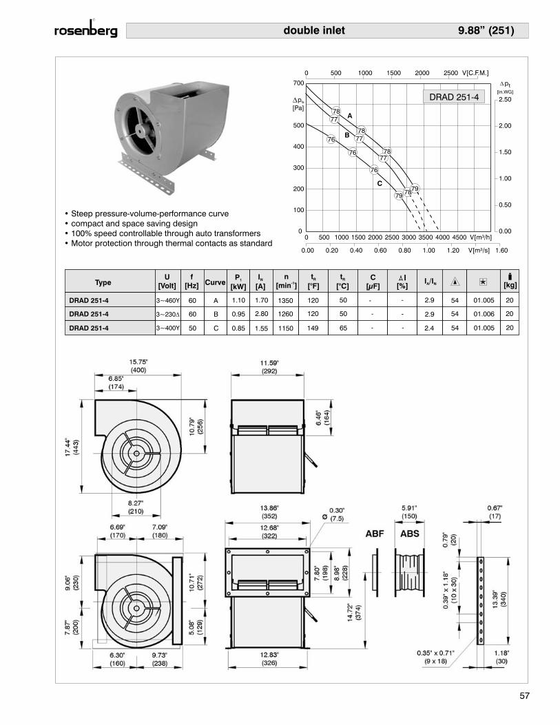
9.88” (251)
TypeU
[Volt]
f
[Hz] CurveP
[kW]1
I
[A]N
n
[min ]-1
t
[°C]R C
[μF] [%]I /IA N [kg]
t
[°F]R
DRAD 251-4
DRAD 251-4
DRAD 251-4
3~460Y
3~230�
3~400Y
60
60
50
A
B
C
1.10 1.70 1350 120 50 - - 2.9 54 01.005 20
0.95 2.80 1260 120 50 - - 2.9 54 01.006 20
0.85 1.55 1150 149 65 - - 2.4 54 01.005 20
57
• Steep pressure-volume-performance curve
• compact and space saving design
• 100% speed controllable through auto transformers
• Motor protection through thermal contacts as standard
double inlet
78
78
78
7978
DRAD 251-4
A
B
C79
77
76
76
76
77
77
p
[Pa]fa

9.88” (251)
TypeU
[Volt]
f
[Hz] CurveP
[kW]1
I
[A]N
n
[min ]-1
t
[°C]R C
[μF] [%]I /IA N [kg]
t
[°F]R
DRAE 251-4L
DRAE 251-4L
DRAE 251-4L
1~120
1~230
1~230
60
60
50
A
A
B
1.50 13.0 1430 122 50 80 17 1.9 54 01.025 26
1.50 6.50 1430 122 50 20 17 1.9 54 01.025 26
1.35 6.00 1240 131 55 20 5 1.5 54 01.025 26
58
• Steep pressure-volume-performance curve
• compact and space saving design
• 100% speed controllable through auto transformers
• Motor protection through thermal contacts as standard
double inlet
0 1000 2000 3000 4000 V[m³/h] 6000
0.00 0.20 0.40 0.60 0.80 1.00 1.20 V[m³/s] 1.60
0 500 1000 1500 2000 2500 V[C.F.M.] 3500
0
100
200
300
400
500
700
0.00
0.50
1.00
1.50
2.00
2.50DRAE 251-4L
A
B
77
80
81
79
[in.WG]
pst
p
[Pa]fa

9.88” (251)
TypeU
[Volt]
f
[Hz] CurveP
[kW]1
I
[A]N
n
[min ]-1
t
[°C]R C
[μF] [%]I /IA N [kg]
t
[°F]R
60
60
50
A
B
C
DRAD 251-4 L
DRAD 251-4 L
DRAD 251-4 L
3~460Y
3~230�
3~400Y
1.50 2.60 1550 120 50 - - 3.7 54 01.005 24
1.40 4.20 1490 120 50 - - 3.7 54 01.006 24
1.10 2.50 1300 120 50 - - 3.5 54 01.005 24
59
• Steep pressure-volume-performance curve
• compact and space saving design
• 100% speed controllable through auto transformers
• Motor protection through thermal contacts as standard
double inlet
DRAD 251-4L
A
BC
78
81
79
75
78
73
78
73
80
78
p
[Pa]fa

10.98” (279)
TypeU
[Volt]
f
[Hz] CurveP
[kW]1
I
[A]N
n
[min ]-1
t
[°C]R C
[μF] [%]I /IA N [kg]
t
[°F]R
60
60
50
A
B
C
DRAE 279-4 IP10
DRAE 279-4 IP10
DRAE 279-4 IP10
1.70 14.8 1235 120 50 100 - 1.5 10 01.025 27
1.70 7.40 1235 120 50 25 - 1.5 10 01.025 27
1.65 7.30 1050 120 50 25 - 1.5 10 01.025 27
1~120
1~230
1~230
60
• Steep pressure-volume-performance curve
• compact and space saving design
• 100% speed controllable through auto transformers
• Motor protection through thermal contacts as standard
double inlet
DRAE 279-4 IP10
A
B
79
78
80
81
78
82
85
80
p
[Pa]fa

10.98” (279)
TypeU
[Volt]
f
[Hz] CurveP
[kW]1
I
[A]N
n
[min ]-1
t
[°C]R C
[μF] [%]I /IA N [kg]
t
[°F]R
60
60
50
A
B
C
DRAD 279-4 IP54
DRAD 279-4 IP54
DRAD 279-4 IP54
2.20 3.60 1400 104 40 - - 2.9 54 01.005 27
2.00 6.20 1300 104 40 - - 2.9 54 01.006 27
1.80 3.40 1170 120 50 - - 2.7 54 01.005 27
3~460Y
3~230�
3~400D
61
• Steep pressure-volume-performance curve
• compact and space saving design
• 100% speed controllable through auto transformers
• Motor protection through thermal contacts as standard
double inlet
A
B
C
82
82
81
82
84
80
81
80
78
78
79
DRAD 279-4 IP54
83
p
[Pa]fa

11.06” (281)
TypeU
[Volt]
f
[Hz] CurveP
[kW]1
I
[A]N
n
[min ]-1
t
[°C]R C
[μF] [%]I /IA N [kg]
t
[°F]R
DRAE 281-4 IP10
DRAE 281-4 IP10
DRAE 281-4L IP10
1~120
1~230
1~230
60
60
50
A
A
B
1.70 14.8 1230 122 50 100 - 1.5 10 01.025 30
1.70 7.40 1230 122 50 25 - 1.5 10 01.025 30
1.70 7.40 1010 122 50 25 - 1.5 54 01.025 30
62
• Steep pressure-volume-performance curve
• compact and space saving design
• 100% speed controllable through auto transformers
• Motor protection through thermal contacts as standard
double inlet
0 1000 2000 3000 4000 5000 V[m³/h] 7000
0.00 0.20 0.40 0.60 0.80 1.00 1.20 1.40 1.60V[m³/s] 2.00
0 500 1000 1500 2000 2500 3000 V[C.F.M.] 4000
0
100
200
300
400
500
600
800
0.00
0.50
1.00
1.50
2.00
3.00DRAE 281-4 IP10A
B
78
80
82
81
[in.WG]
pst
p
[Pa]fa

11.06” (281)
TypeU
[Volt]
f
[Hz] CurveP
[kW]1
I
[A]N
n
[min ]-1
t
[°C]R C
[μF] [%]I /IA N [kg]
t
[°F]R
60
60
50
A
B
C
DRAD 281-4 IP10
DRAD 281-4 IP10
DRAD 281-4 IP10
3~460Y
3~230�
3~400D
2.50 3.90 1340 120 50 - - 2.5 10 01.005 32
2.20 6.40 1250 120 50 - - 2.5 10 01.006 32
1.90 3.60 1140 130 55 - - 3.4 10 01.005 32
63
• Steep pressure-volume-performance curve
• compact and space saving design
• 100% speed controllable through auto transformers
• Motor protection through thermal contacts as standard
double inlet
DRAD 281-4 IP10
A
B
C
82
81
81
82
84
80
81
83
79
78
79
p
[Pa]fa

11.06” (281)
TypeU
[Volt]
f
[Hz] CurveP
[kW]1
I
[A]N
n
[min ]-1
t
[°C]R C
[μF] [%]I /IA N [kg]
t
[°F]R
60
60
50
A
B
C
DRAD 281-4
DRAD 281-4
DRAD 281-4
3~460Y
3~230�
3~400D
2.20 3.60 1400 104 40 - - 2.9 54 01.005 32
2.00 5.90 1310 104 40 - - 2.9 54 01.006 32
1.90 3.60 1140 104 40 - - 2.7 54 01.006 32
64
• Steep pressure-volume-performance curve
• compact and space saving design
• 100% speed controllable through auto transformers
• Motor protection through thermal contacts as standard
double inlet
DRAD 281-4
A
B
C
82
81
81
82
84
80
81
83
79
78
79
p
[Pa]fa
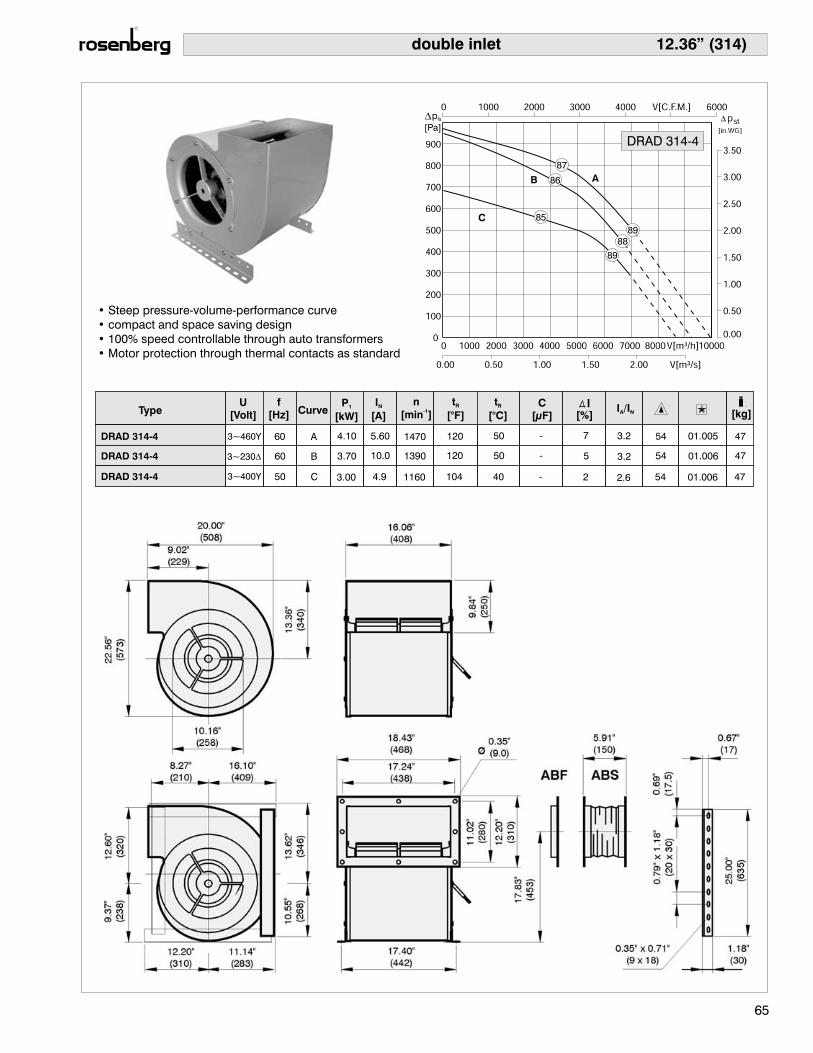
12.36” (314)
TypeU
[Volt]
f
[Hz] CurveP
[kW]1
I
[A]N
n
[min ]-1
t
[°C]R C
[μF] [%]I /IA N [kg]
t
[°F]R
60
60
50
A
B
C
DRAD 314-4
DRAD 314-4
DRAD 314-4
3~460Y
3~230�
3~400Y
4.10 5.60 1470 120 50 - 7 3.2 54 4701.005
3.70
3.00
10.0
4.9
1390
1160
120
104
50
40
-
-
5
2
3.2
2.6
54 47
54 47
01.006
01.006
65
• Steep pressure-volume-performance curve
• compact and space saving design
• 100% speed controllable through auto transformers
• Motor protection through thermal contacts as standard
double inlet
AB
C
87
89
86
85
88
89
DRAD 314-4
p
[Pa]fa

14.02” (356) double inlet
TypeU
[Volt]
f
[Hz] CurveP
[kW]1
I
[A]N
n
[min ]-1
t
[°C]R C
[μF] [%]I /IA N [kg]
t
[°F]R
60
60
50
A
B
C
DRAD 356-4 IP10
DRAD 356-4 IP10
DRAD 356-4 IP10
3~460Y
3~230�
3~400Y
5.80 8.10 1410 120 50 - 2 2.4 10 01.005 71
5.10 14.0 1330 120 50 - 2 2.4 10 01.006 71
5.30 8.40 1140 120 50 - - 2.6 10 01.006 71
66
• Steep pressure-volume-performance curve
• compact and space saving design
• 100% speed controllable through auto transformers
• Motor protection through thermal contacts as standard
A
BC 90
93
90
91
89
90
DRAD 356-4 IP10
p
[Pa]fa
67
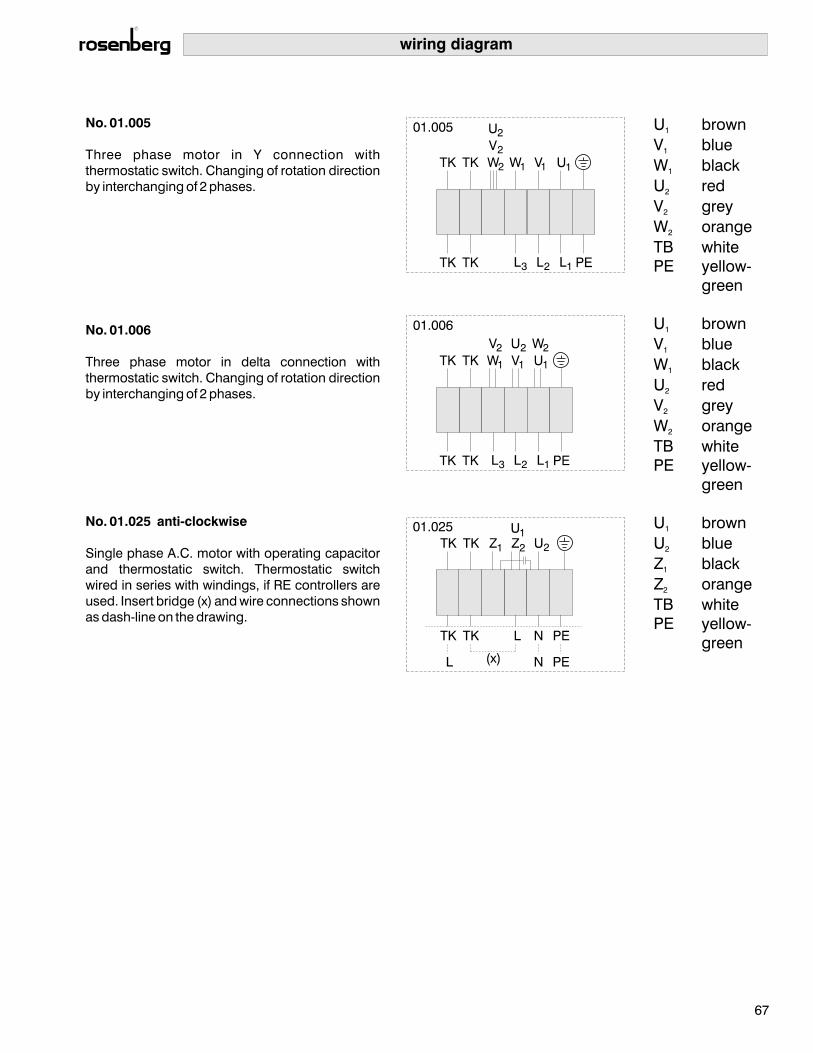
wiring diagram
No. 01.005
No. 01.006
No. 01.025 anti-clockwise
Three phase motor in Y connection with
thermostatic switch. Changing of rotation direction
by interchanging of 2 phases.
Three phase motor in delta connection with
thermostatic switch. Changing of rotation direction
by interchanging of 2 phases.
Single phase A.C. motor with operating capacitor
and thermostatic switch. Thermostatic switch
wired in series with windings, if RE controllers are
used. Insert bridge (x) and wire connections shown
as dash-line on the drawing.
U brown
V blue
W black
U red
V grey
W orange
TB white
PE yellow-
green
1
1
1
2
2
2
U brown
V blue
W black
U red
V grey
W orange
TB white
PE yellow-
green
U brown
U blue
Z black
Z orange
TB white
PE yellow-
green
1
1
1
2
2
2
1
2
1
2

Notices
68