Embed Size (px)
Citation preview

CENTRON® Bridge Meter Functional Overview CENTRON® Bridge

Identification CENTRON Bridge Meter Functional Overview 12 August 2014 TDC-1342-002 CENTRON Bridge Meter Copyright © 2012-2014 Itron, Inc. All rights reserved. Confidentiality Notice The information contained herein is proprietary and confidential and is being provided subject to the condition that (i) it be held in confidence except to the extent required otherwise by law and (ii) it will be used only for the purposes described herein. Any third party that is given access to this information shall be similarly bound in writing. Trademark Notice Itron is a registered trademark of Itron, Inc. All other product names and logos in this documentation are used for identification purposes only and may be trademarks or registered trademarks of their respective companies. Suggestions If you have comments or suggestions on how we may improve this documentation, send them to [email protected] For more information about Itron or Itron products, see www.itron.com If you have questions or comments about the software or hardware product, contact Itron Technical Support Services. Contact Telephone Support 1-877-487-6602 Email Support [email protected] Web/Itron Access support.itron.com
Overview......................................................................................................................... 4
About This Document .......................................................................................................................... 4
Chapter 1 CENTRON Bridge Meter Operation ............................................................ 5
Bridge Meter Functionality ................................................................................................................... 6 SCM+ Message Format ...................................................................................................................... 6 ChoiceConnect Enhanced Security .................................................................................................... 7 Service Switch ..................................................................................................................................... 8 Demand Reset .................................................................................................................................... 8 Tamper and Status Indicators ............................................................................................................. 9 Time of Use (TOU) .............................................................................................................................. 9
TOU Schedules ......................................................................................................................... 9 Calendar Schedule ....................................................................................................... 10 Rates............................................................................................................................. 10 Daily Patterns ............................................................................................................... 10 Day Types ..................................................................................................................... 10 Holidays ........................................................................................................................ 10 Seasonal Schedules ..................................................................................................... 10
Register Capabilities ......................................................................................................................... 10 Energy Registers..................................................................................................................... 11 Demand Registers .................................................................................................................. 11
Load Profile Data Collection and Storage Values ............................................................................. 12 Manufacturing Requirements ............................................................................................................ 12
Chapter 2 Supported Software and Hardware ......................................................... 13
Supported Software ........................................................................................................................... 13 Supported Hardware Collection Devices .......................................................................................... 13
Chapter 3 Changing Meter Operation Modes ........................................................... 15
From ChoiceConnect to OpenWay Mode ......................................................................................... 15 From ChoiceConnect to OpenWay Mode in a Cisco Network .......................................................... 15 From OpenWay to ChoiceConnect Mode ......................................................................................... 15
Supported Meter Forms .............................................................................................. 16
Glossary ....................................................................................................................... 17
Contents
CENTRON® Bridge Functional Overview iii Proprietary and Confidential

The CENTRON Bridge meter is the bridge between Itron communication architectures that enable Advanced Metering Infrastructure (AMI) and smart grid functionality. The meter’s adaptability allows it to be incorporated alongside existing Itron electric meters with a mobile meter data collection system, delivering advanced metering benefits associated with remote service disconnects, demand metering (real-time resetting), net metering, time of use rates, and interval data for customer service and engineering.
When prudent for the utility, the CENTRON Bridge can easily migrate to a full smart grid solution, offering demand response and distribution automation benefits. With CENTRON Bridge’s versatility and proven operational benefits, utilities can address current business challenges and see an immediate return on investment, all while readying for a full smart grid solution as the need develops. Enabled to leverage field assets across two different data collection solutions, a utility can protect and extend its original investment.
About This Document This document provides a high level overview of Itron’s CENTRON Bridge meter and the CENTRON Bridge Polyphase meter. This document also provides information on how you can deploy these meters to migrate from an Itron ChoiceConnect® environment to an Itron OpenWay® network, and considerations that should be taken into account when designing your operational mode transition plan.
After transitioning to OpenWay mode, the meter becomes compatible with OpenWay systems. See the OpenWay documentation suite for information about using the CENTRON Bridge in OpenWay mode.
Overview
CENTRON® Bridge Functional Overview 4 Proprietary and Confidential
The CENTRON Bridge meter is installed just like any other electric meter. Just take the meter into the field and physically install it. When the CENTRON Bridge meter powers up it is in AMR (ChoiceConnect®) mode. This means that it is transmitting an SCM+ message every 30 seconds. The SCM+ message contains the consumption reading, tampers, errors, service switch status, ERT Type(14), and ERT ID. While in AMR mode the meter is read using the Field Collection System (FCS) with an MC3, MCLite, or FC300SR collection device. Additional two-way commands can be used to interface with the meter for:
• Collecting up to five different energy values
• Collecting two channels of interval data
• Collecting demand readings and resetting the demand
• Disconnecting or connecting service
• Collecting Time of Use data
• Updating Time of use calendars in the meter
• Modifying the security state of the meter
• Scheduling the transition from mobile to OpenWay
When the CENTRON Bridge meter is transitioned to operate in OpenWay RFLAN mode it assumes all operating characteristics of the HW 3.1 OpenWay meter.
Note Register firmware 3.032.xxx and 5.008.xxx are the only versions of OpenWay register firmware that support communication with ChoiceConnect Mobile meter reading software. CENTRON Bridge meters with ChoiceConnect comm module firmware version 0.21.xx must have register firmware version 3.032.xxx. Meters with ChoiceConnect comm module firmware version 0.30.xx must have register firmware version 5.008.xxx.
C H A P T E R 1
CENTRON Bridge Meter Operation
CENTRON® Bridge Functional Overview 5 Proprietary and Confidential
CENTRON Bridge Meter Operation
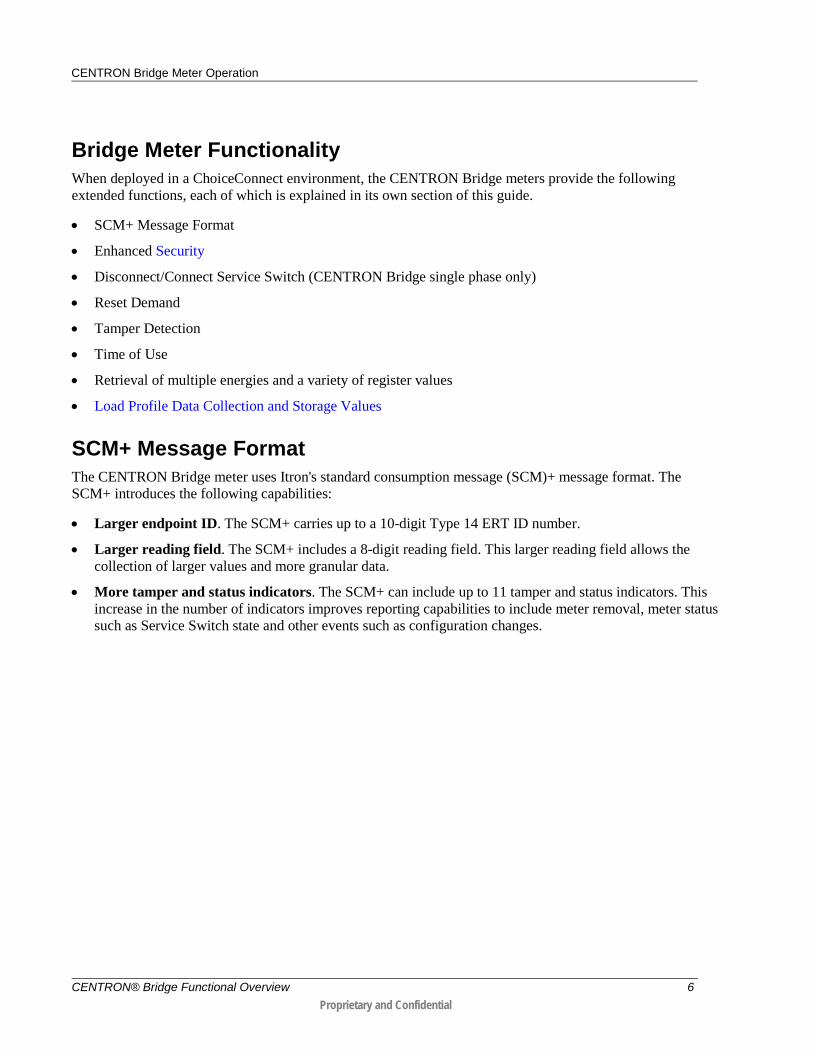
Bridge Meter Functionality When deployed in a ChoiceConnect environment, the CENTRON Bridge meters provide the following extended functions, each of which is explained in its own section of this guide.
• SCM+ Message Format
• Enhanced Security
• Disconnect/Connect Service Switch (CENTRON Bridge single phase only)
• Reset Demand
• Tamper Detection
• Time of Use
• Retrieval of multiple energies and a variety of register values
• Load Profile Data Collection and Storage Values
SCM+ Message Format The CENTRON Bridge meter uses Itron's standard consumption message (SCM)+ message format. The SCM+ introduces the following capabilities:
• Larger endpoint ID. The SCM+ carries up to a 10-digit Type 14 ERT ID number.
• Larger reading field. The SCM+ includes a 8-digit reading field. This larger reading field allows the collection of larger values and more granular data.
• More tamper and status indicators. The SCM+ can include up to 11 tamper and status indicators. This increase in the number of indicators improves reporting capabilities to include meter removal, meter status such as Service Switch state and other events such as configuration changes.
CENTRON® Bridge Functional Overview 6 Proprietary and Confidential

CENTRON Bridge Meter Operation
ChoiceConnect Enhanced Security In ChoiceConnect mode the CENTRON Bridge meter can be configured to run at any of three security levels, each of which determines which meter features are available for use.
• Ready to secure. At this level no enhanced security is enabled. The meter responds only to read commands, which pull data from the meter but do not change the meter’s settings. The meter’s remote connect and disconnect, demand reset, and operation mode change features are unavailable.
• Command security. At this level you must use secure commands to access the meter’s remote connect and disconnect, demand reset, and operation mode change functions. It does not require the use of secure commands for reading meter data.
• Full security. At this level the meter requires the use of secure commands for all command and reading functions.
CENTRON Bridge meters arrive from the factory in ChoiceConnect operation mode with command security enabled. Your utility’s public key along with the factory, revocation, recovery, and command keys are all injected into the meter during the manufacturing process. After the meter is installed, you can use supported versions of Field Deployment Manager (FDM) or Field Collection System (FCS) with Itron Security Manager to change the meter’s security level if desired and to obtain the security keys and secure commands required for the security level in which you want to operate the meter.
During the transition from ChoiceConnect mode to OpenWay mode, security keys are used in conjunction with the OpenWay Collection Engine to transfer the production keys that the meter requires to operate in an OpenWay enhanced security mode. After the meter’s operation mode is changed from ChoiceConnect to OpenWay, the meter operates consistently with the functionality supported by your OpenWay network. For more information about OpenWay network security, see your OpenWay documentation.
The meter’s operation mode can be changed from OpenWay back to ChoiceConnect, if necessary. ChoiceConnect security keys that are in the meter before the transition to OpenWay mode are available if the meter is switched back to ChoiceConnect security.
CENTRON® Bridge Functional Overview 7 Proprietary and Confidential
CENTRON Bridge Meter Operation
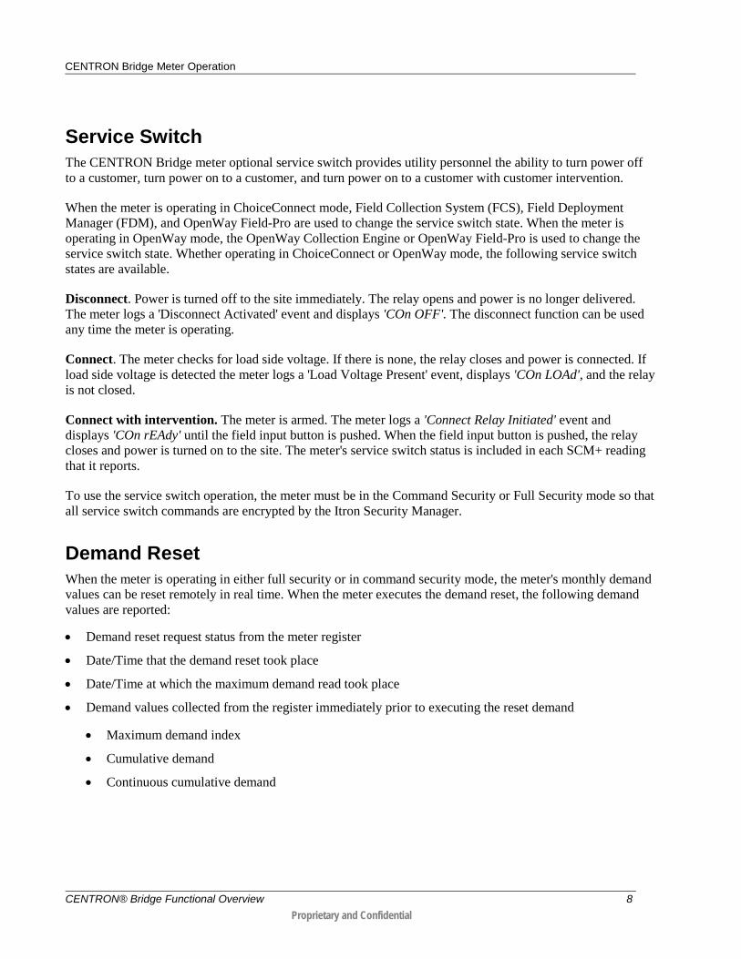
Service Switch The CENTRON Bridge meter optional service switch provides utility personnel the ability to turn power off to a customer, turn power on to a customer, and turn power on to a customer with customer intervention.
When the meter is operating in ChoiceConnect mode, Field Collection System (FCS), Field Deployment Manager (FDM), and OpenWay Field-Pro are used to change the service switch state. When the meter is operating in OpenWay mode, the OpenWay Collection Engine or OpenWay Field-Pro is used to change the service switch state. Whether operating in ChoiceConnect or OpenWay mode, the following service switch states are available.
Disconnect. Power is turned off to the site immediately. The relay opens and power is no longer delivered. The meter logs a 'Disconnect Activated' event and displays 'COn OFF'. The disconnect function can be used any time the meter is operating.
Connect. The meter checks for load side voltage. If there is none, the relay closes and power is connected. If load side voltage is detected the meter logs a 'Load Voltage Present' event, displays 'COn LOAd', and the relay is not closed.
Connect with intervention. The meter is armed. The meter logs a 'Connect Relay Initiated' event and displays 'COn rEAdy' until the field input button is pushed. When the field input button is pushed, the relay closes and power is turned on to the site. The meter's service switch status is included in each SCM+ reading that it reports.
To use the service switch operation, the meter must be in the Command Security or Full Security mode so that all service switch commands are encrypted by the Itron Security Manager.
Demand Reset When the meter is operating in either full security or in command security mode, the meter's monthly demand values can be reset remotely in real time. When the meter executes the demand reset, the following demand values are reported:
• Demand reset request status from the meter register
• Date/Time that the demand reset took place
• Date/Time at which the maximum demand read took place
• Demand values collected from the register immediately prior to executing the reset demand
• Maximum demand index
• Cumulative demand
• Continuous cumulative demand
CENTRON® Bridge Functional Overview 8 Proprietary and Confidential
CENTRON Bridge Meter Operation
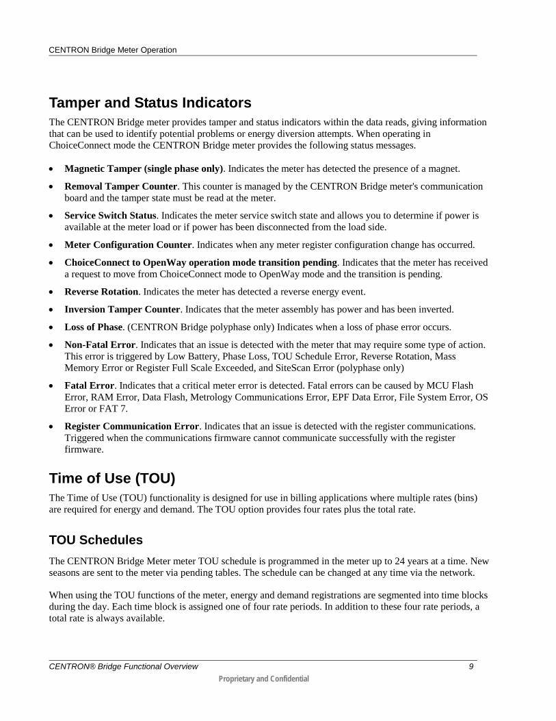
Tamper and Status Indicators The CENTRON Bridge meter provides tamper and status indicators within the data reads, giving information that can be used to identify potential problems or energy diversion attempts. When operating in ChoiceConnect mode the CENTRON Bridge meter provides the following status messages.
• Magnetic Tamper (single phase only). Indicates the meter has detected the presence of a magnet.
• Removal Tamper Counter. This counter is managed by the CENTRON Bridge meter's communication board and the tamper state must be read at the meter.
• Service Switch Status. Indicates the meter service switch state and allows you to determine if power is available at the meter load or if power has been disconnected from the load side.
• Meter Configuration Counter. Indicates when any meter register configuration change has occurred.
• ChoiceConnect to OpenWay operation mode transition pending. Indicates that the meter has received a request to move from ChoiceConnect mode to OpenWay mode and the transition is pending.
• Reverse Rotation. Indicates the meter has detected a reverse energy event.
• Inversion Tamper Counter. Indicates that the meter assembly has power and has been inverted.
• Loss of Phase. (CENTRON Bridge polyphase only) Indicates when a loss of phase error occurs.
• Non-Fatal Error. Indicates that an issue is detected with the meter that may require some type of action. This error is triggered by Low Battery, Phase Loss, TOU Schedule Error, Reverse Rotation, Mass Memory Error or Register Full Scale Exceeded, and SiteScan Error (polyphase only)
• Fatal Error. Indicates that a critical meter error is detected. Fatal errors can be caused by MCU Flash Error, RAM Error, Data Flash, Metrology Communications Error, EPF Data Error, File System Error, OS Error or FAT 7.
• Register Communication Error. Indicates that an issue is detected with the register communications. Triggered when the communications firmware cannot communicate successfully with the register firmware.
Time of Use (TOU) The Time of Use (TOU) functionality is designed for use in billing applications where multiple rates (bins) are required for energy and demand. The TOU option provides four rates plus the total rate.
TOU Schedules The CENTRON Bridge Meter meter TOU schedule is programmed in the meter up to 24 years at a time. New seasons are sent to the meter via pending tables. The schedule can be changed at any time via the network.
When using the TOU functions of the meter, energy and demand registrations are segmented into time blocks during the day. Each time block is assigned one of four rate periods. In addition to these four rate periods, a total rate is always available.
CENTRON® Bridge Functional Overview 9 Proprietary and Confidential

CENTRON Bridge Meter Operation
Calendar Schedule The CENTRON Bridge Meter meter supports a 24 year calendar. The calendar schedule contains all daily information needed for the meter to measure and register data in real time. The schedule contains daily patterns with configurable day types and rates.
Rates The TOU rates are applied to all energy and demand registers that have been selected for measurement. Therefore, all energy and demand registers are segmented as per the TOU schedule and available in each rate period, in addition to the Total rate.
Daily Patterns Each pattern defines the times during the day that rate period A, B, C, or D begins and ends. Up to six rate period changes may be specified for each daily pattern.
Day Types There are four day types: Weekday, Saturday, Sunday, and Holiday. Each day of the week is assigned to one of the four day types. Each day type is assigned one of the four daily patterns when each season is defined. Any of the daily patterns can be used in any combination with the day types.
Holidays Holidays can be set up either as Fixed or Recurring. Fixed holidays are defined as a single date. Recurring holidays repeat every year. The Recurring Date Type options allow you to determine whether the holiday occurs on the same date every year or moves to another day if the date falls on a Saturday or Sunday.
A maximum of 14 holidays can be set up per season.
Seasonal Schedules A season is a period during the year when a particular rate structure is in effect. Multiple seasons can be set up per year. Only one seasonal TOU calendar can operate within the meter at a time.
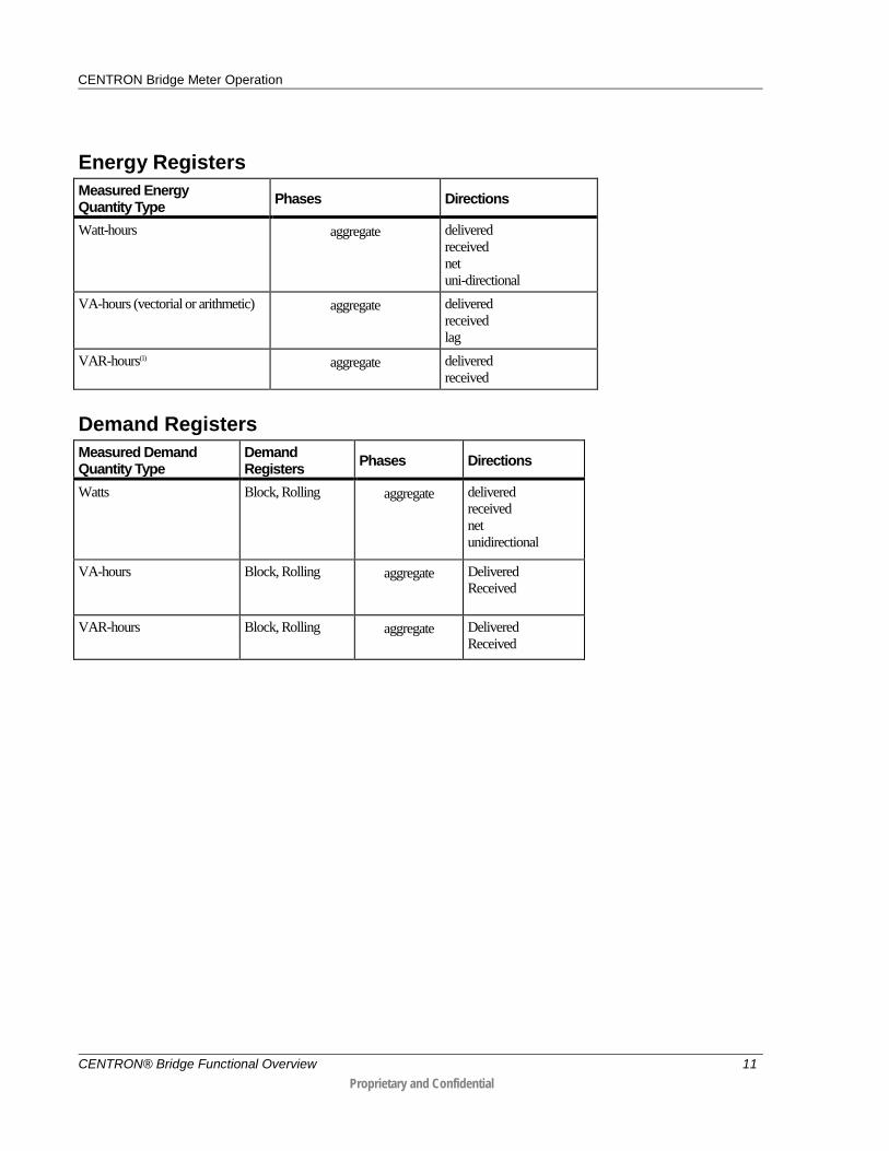
Register Capabilities The register can measure numerous energy quantities (as shown in the table below) from which the user can configure up to four to be registered.
If an energy register is edited, the corresponding load profile interval data will be affected.
CENTRON® Bridge Functional Overview 10 Proprietary and Confidential
CENTRON Bridge Meter Operation
Energy Registers Measured Energy Quantity Type Phases Directions
Watt-hours aggregate delivered received net uni-directional
VA-hours (vectorial or arithmetic) aggregate delivered received lag
VAR-hours(1)
aggregate delivered received
Demand Registers Measured Demand Quantity Type
Demand Registers Phases Directions
Watts Block, Rolling aggregate delivered received net unidirectional
VA-hours
Block, Rolling aggregate Delivered Received
VAR-hours
Block, Rolling aggregate Delivered Received
CENTRON® Bridge Functional Overview 11 Proprietary and Confidential

CENTRON Bridge Meter Operation
Load Profile Data Collection and Storage Values The CENTRON Bridge meter collects and stores up to 40 days’ of 15 minute consumption. The following historical usage data is readily available:
• Billing inquiries can quickly and accurately be addressed in real-time.
• Move-in and move-out reads no longer require an off-cycle reading.
• Manually keyed reads can be audited for accuracy without sending field personnel to the service location.
• Two channels of hourly and 15-minute consumption data can be used to facilitate load studies and to enable time-based rates.
You can set up Field Collection System (FCS) to collect load profile values in the following ways:
• Specific date/time reading. Returns a single consumption (historical) reading. It consists of a calculated index reading for a specific date and hour. This is typically used for move-in/move-out readings.
• 40 daily readings. Returns daily consumption readings for a specified hour of the day on each of the last 40 days before the current date.
• 24 hourly intervals. Returns a series of consumption totals recorded during hourly intervals bracketed by 24 calculated hourly readings and ending at a specified date/hour.
• All intervals. Returns the meter’s entire table of data for the previous 40 days of hourly or 15 minute intervals, from the date and time the read is requested.
Manufacturing Requirements CENTRON Bridge meters are built to order and shipped in ChoiceConnect operation mode with command security enabled so the meter requires little or no configuration before installation. When ordering meters, you must provide the following information, which is configured into the meter during manufacturing.
• Meter passwords. Your ANSI C12.18 Protocol security password, which is used for accessing the meter with an optical probe.
• Security Credentials. Because meters arrive with ChoiceConnect command security, your public utility key is required to encrypt the meter security key pairs. These key pairs are then injected into the meter's communication module. Also, for future migration possibilities your OpenWay Shared Key File is also required.
• Meter Configuration. A customer specific meter configuration must be built for each meter type. This includes but is not limited to energy values, demand values, load profile and display formatting.
CENTRON® Bridge Functional Overview 12 Proprietary and Confidential

Supported Software Security
While the meter is operating in ChoiceConnect mode, end-to-end security is provided by Itron Security Manager (ISM) v3.0 interfaced with Field Collection System (FCS) v2.7 or later or with Field Deployment Manager (FDM) v3.6 or later. While the meter is operating in OpenWay mode, security is handled by the ISM.
Workforce Management
When the CENTRON Bridge meter is operating in ChoiceConnect mode, use Field Deployment Manager (FDM) Endpoint Tools Enhanced v3.6 and later versions to change security settings. Use FDM Endpoint Tools Enhanced v3.6 and later versions or OpenWay Field-Pro v3.51 and later versions for maintenance, diagnostics, and reading activities such as operating the service switch, changing configurations, and downloading firmware.
When the meter is operating in OpenWay mode, use OpenWay Field-Pro v2.x and later for maintenance, diagnostics, and reading activities such as operating the service switch, changing configurations, and downloading firmware. Field-Pro can communicate with the meter by means of a ZigBee® radio or through the meter's optical port by means of an optical probe.
Data Collection
While operating in ChoiceConnect mode, Field Collection System (FCS) v2.7 or later is the only meter reading application that supports the all advanced AMR activities of the CENTRON Bridge meter. If you have an earlier version of FCS or an older meter reading application, you must upgrade to a supported FCS version. MV-RS or later also supports reading the SCM+ message.
Customer Information Systems/Billing Systems
Itron’s new SCM+ format supports endpoint IDs up to 10 digits long. The change from 8 digits to 10 digits affects many systems, not just Itron systems. Evaluate all of your organization’s software and database systems that store endpoint IDs for potential effects from the change to SCM+. The first CENTRON Bridge meters are being shipped with 8-digit endpoint IDs, but you should prepare your systems for future 9-digit and 10-digit IDs.
Supported Hardware Collection Devices When operating in ChoiceConnect mode, the meter can be read by a supported meter reading application installed on one of the following devices:
• FC300 handheld computer with Itron radio
• Mobile Collection System (MC3)
• Mobile Collector Lite (MCLite) radio
C H A P T E R 2
Supported Software and Hardware
CENTRON® Bridge Functional Overview 13 Proprietary and Confidential
Supported Software and Hardware
Note While the meter is operating in ChoiceConnect mode, you must use Mobile Collection System (MC3) v3.7 or later or Mobile Collector Lite (MCLite) for mobile data collection.
Evaluate your hardware collection devices and replace unsupported devices as necessary. Not all Mobile Collection systems and MCLite radios support the CENTRON Bridge meter’s two-way capabilities. Verify that the appropriate firmware has been installed on your hardware device to support the SCM+ message format. See the device documentation for further details.
CENTRON® Bridge Functional Overview 14 Proprietary and Confidential
The CENTRON Bridge meter operates securely in either of two modes, ChoiceConnect mode or OpenWay mode. You can switch it from ChoiceConnect operation mode to OpenWay operation mode and, if needed, back to ChoiceConnect mode. The meter operates in one of these two modes at all times, but not both.
From ChoiceConnect to OpenWay Mode Before you switch a CENTRON Bridge meter from ChoiceConnect mode to OpenWay mode, you must have an operational OpenWay network covering the area where the meter is installed. Additionally, your utility must have a complete installation and configuration of OpenWay services, including the OpenWay Collection Engine and the OpenWay security appliance.
Next, determine the date and time you want to perform the transition from ChoiceConnect mode to OpenWay mode. FCS administrators can use FCS application global settings to enable the transition commands and date and time on CENTRON Bridge meters in routes selected by the FCS operator.
FCS includes the mode change commands in route data when the designated meters are sent to the field. This can be done in special routes or as part of normal meter reading route processing. As each meter is processed, the handheld or mobile collector sends the mode change command to the meter along with the date and time for the change to occur.
When the scheduled change date and time occurs, the meter firmware switches from ChoiceConnect to OpenWay mode. The meter ceases to broadcast the SCM+ message, begins transmitting the OpenWay radio protocol to establish communication with OpenWay devices, and starts building the OpenWay mesh network.
Security in the meter changes from the ChoiceConnect security model to the OpenWay security model immediately as the mode transition starts, and if necessary, the OpenWay Collection Engine sends the meter new security keys. If a newer version of the meter firmware exists, use the OpenWay Collection Engine to download the firmware to the meter.
From ChoiceConnect to OpenWay Mode in a Cisco Network When the meter is successfully registered with the OpenWay system in a Cisco network, use the OpenWay Collection Engine to download the Cisco firmware into the meter.
From OpenWay to ChoiceConnect Mode You can switch meter operation from OpenWay mode back to ChoiceConnect mode using OpenWay Field-Pro and either an optical probe or a ZigBee radio to log on to the meter. Once the meter has reverted to ChoiceConnect mode, it ceases to transmit on the OpenWay radio frequency and begins broadcasting the ChoiceConnect SCM+.
Note After you switch the meter to an OpenWay network, if you update meter’s firmware, you can no longer switch the meter back to ChoiceConnect mode.
C H A P T E R 3
Changing Meter Operation Modes
CENTRON® Bridge Functional Overview 15 Proprietary and Confidential
Supported Meter Forms
The CENTRON Bridge meter is available in the following meter forms:
Single-phase 1S CL200*
2S CL200*
12S/25S CL200*
2S CL320
Polyphase 3S CL20
4S CL20
9S CL20
9S/36S CL20
45S/5S CL20
1S CL100
2S CL200
12S CL200
16S CL200
2S CL320
12S Cl320
16S CL320
* Available with optional disconnect/connect service switch (see Disconnect/Connect Service Switch).
Supported Meter Forms
CENTRON® Bridge Functional Overview 16 Proprietary and Confidential
advanced metering infrastructure (AMI) Utility metering and communications system that leverages two-way communication between a utility company and smart energy management devices, including smart meters, thermostats, and other energy management devices. AMI provides utility companies real-time consumption data, and provides customers detailed usage data. AMI systems support capabilities such as load control, time-of-use and critical-peak pricing, and outage and restoration reporting.
An AMI system consists of the following components:
• Smart meters that collect and store interval consumption data, interface with, and collect and store data from other devices, such as other meters. Smart meters can also initiate and respond to two-way communications with the utility.
• Home gateway devices that communicate with and control energy-using appliances throughout the home, and can communicate with the utility.
• A network over which smart meters, home gateway devices, and other AMI components execute two-way communications to transmit data and commands between the utility and the home.
• A meter data management (MDM) system to which the collected data is delivered. MDM systems can interface with other utility systems, such as customer information systems (CISs), outage management systems (OMSs), and workforce management systems (WMSs).
Utility industr y ter ms|
AMI advanced metering infrastructure Utility metering and communications system that leverages two-way communication between a utility company and smart energy management devices, including smart meters, thermostats, and other energy management devices. AMI provides utility companies real-time consumption data, and provides customers detailed usage data. AMI systems support capabilities such as load control, time-of-use and critical-peak pricing, and outage and restoration reporting.
An AMI system consists of the following components:
• Smart meters that collect and store interval consumption data, interface with, and collect and store data from other devices, such as other meters. Smart meters can also initiate and respond to two-way communications with the utility.
• Home gateway devices that communicate with and control energy-using appliances throughout the home, and can communicate with the utility.
• A network over which smart meters, home gateway devices, and other AMI components execute two-way communications to transmit data and commands between the utility and the home.
• A meter data management (MDM) system to which the collected data is delivered. MDM systems can interface with other utility systems, such as customer information systems (CISs), outage management systems (OMSs), and workforce management systems (WMSs).
Utility industr y ter ms|Abbrevi ati ons|
Glossary
CENTRON® Bridge Functional Overview 17 Proprietary and Confidential
Glossary
ANSI C12.18 The American National Standards Institute (ANSI) protocol used to transport data through the optical ports used on most North American electricity meters. Utility industr y ter ms|OpenWay|ChoiceC onnect|
block interval demand Demand based on intervals from 1 to 60 minutes. All calculations of demand are based on rolling demand. To calculate block interval demand, you must program the meter register to have one subinterval of the same length as the demand interval. Utility industr y ter ms|OpenWay|ChoiceC onnect|
ChoiceConnect® Itron’s comprehensive suite of ERT module-based automated meter reading (AMR) systems. ChoiceConnect includes walk-by, drive-by, and fixed network meter data collection solutions, all using Itron’s 900-MHz endpoint technology. Itron produc t names|
Collection Engine (CE), OpenWay® The head-end system and the heart of Itron’s OpenWay advanced metering infrastructure (AMI) solution. The CE is a C12.22-compliant software application that collects meter data and manages, upgrades, and in some cases connects and disconnects meters through remote two-way communications. The CE passes collected meter data to the meter data management (MDM) system for storage and manipulation at the utility. It stores information related to registered meter configurations, such as cell relay data, communication paths, group assignments, and firmware versions. OpenWay|
energy diversion The theft and/or unauthorized use of an energy service such as gas, water, or electricity. Utility industr y ter ms|OpenWay|Acti ve SmartGrid Anal ytics|
FC300 ChoiceConnect® Field Collector 300 A rugged and versatile Itron handheld computer equipped with Bluetooth® technology, a 512MB SD card, SRead Radio, and English Windows CE 5.0 Professional operating system. Utility personnel can use the FC300 to program, service, and read endpoints efficiently in the field. Itron produc t names|Abbr eviati ons|
FCS Itron® Field Collection System. Itron’s data collection engine for handheld and mobile AMR systems. FCS collects data from multiple meter types, provides meter data to customer billing applications, and integrates with Itron’s workforce automation tools. Abbrevi ati ons|
CENTRON® Bridge Functional Overview 18 Proprietary and Confidential

Glossary
FDM Itron® Field Deployment Manager.
Itron’s newest meter/endpoint installation and workforce management software solution. FDM supports safe, efficient deployment and maintenance of meters, endpoints, and metering network equipment; automates endpoint programming; electronically captures and validates installation data, reducing errors and site revisits; ensures network connectivity; captures field images and GPS coordinates; and creates work orders for service and quality audit work orders. It includes optional invoicing and inventory management modules. Itron produc t names|
Field Collection System (FCS) Itron’s data collection engine for handheld and mobile AMR systems. FCS collects data from multiple meter types, provides meter data to customer billing applications, and integrates with Itron’s workforce automation tools. Abbrevi ati ons|
Field Deployment Manager (FDM) Itron’s newest meter/endpoint installation and workforce management software solution. FDM supports safe, efficient deployment and maintenance of meters, endpoints, and metering network equipment; automates endpoint programming; electronically captures and validates installation data, reducing errors and site revisits; ensures network connectivity; captures field images and GPS coordinates; and creates work orders for service and quality audit work orders. It includes optional invoicing and inventory management modules. Itron produc t names|
Field-Pro™ An Itron software tool designed to run on a Windows-based PC and used for programming Itron electricity meters in the field, retrieving and viewing meter data, and performing meter diagnostics. Itron produc t names|
interval data/interval reads Electricity, gas, or water consumption data collected at frequent time intervals to provide feedback on usage for billing dispute resolution, conservation efforts, and leak detection (water only), as well as to determine block demand or load profiles. Interval reads measure and store energy usage in regularly measured 15, 30, 60, or 120-minute interval time periods. Interval reads can also be measured in a 1440-minute interval, which represents a 24-hour, daily, time period. Itron company-specific terms|
load profile The profile of a customer’s electricity load or usage pattern over a period of time, sometimes shown as a graph. Itron Enter prise Edi tion|OpenWay|Utility industr y ter ms| Itron C ellul ar Sol utions|
load profile data Electricity consumption data collected at frequent time intervals to provide feedback for determining load profiles. Interval reads measure and store energy usage in regularly measured 15-minute, 30-minute, 60-minute, or 120-minute interval time periods. Also called interval data. Utility industr y ter ms| Itron Enter prise Edition|ChoiceC onnect| Itron C ellul ar Sol utions|OpenWay|
CENTRON® Bridge Functional Overview 19 Proprietary and Confidential

Glossary
Mobile Collection System (MC3) Mobile data collection and administration software applications installed on a ruggedized laptop and radio hardware mounted in a vehicle. MC3 is used for gathering data from endpoints attached to electric, gas, and water meters. It collects the data as the mobile collection vehicle is driven along a route in a process known as drive-by or mobile automated meter reader (AMR), rather than requiring the meter reader to personally access each meter. Itron produc t names|
Mobile Collector Lite (MCLite) An Itron portable drive-by automated meter reading (AMR) solution that uses the Itron FC200 handheld meter data collection device with an external SRead radio to gather consumption and tamper data from electricity, gas, and water radio-based endpoints. MCLite belongs to Itron’s ChoiceConnect suite of products. Itron produc t names|
Multi-Vendor Reading System (MV-RS®) Multi-Vendor Reading System Itron handheld meter reading software. MV-RS is compatible with G5, FC200, and FC300 handheld computers and on Mobile Collection System (MC3) and Mobile Collector Lite (MCLite). The application server supports manually keyed meter reading, walk-by AMR, drive-by AMR, optical probe reading, and MicroNetwork AMR. Itron produc t names|
OpenWay® by Itron Itron’s advanced metering infrastructure (AMI) solution. OpenWay utilizes an open-protocol, standards-based architecture (ANSI C12.22) to meet the objectives of AMI business cases requirements, including two-way communications to each meter; scalability to greater than 10 million meters; multiple-channel interval data collection; on-demand reads; demand reset; a remote load-limiting disconnect/reconnect switch; critical-peak pricing and time-of-use rate updates; net metering for on-site generation; advanced outage detection and restoration notification; tamper and theft detection and remote device configuration and firmware updates. The system also provides local connectivity to gas and water meters, as well as in-home devices via a ZigBee® radio that comes standard in all OpenWay CENTRON® electricity meters.
OpenWay® CENTRON® Meter An Itron electricity meter that is fully compliant with the ANSI C12.19 and C12.22 standards for presentation and transport of register data over a network, providing a secure, open-standards approach to data collection and communications with the meter. In addition, each OpenWay CENTRON meter comes factory-equipped with a ZigBee® radio chip to provide a built-in communications pathway to the home for data presentment, load control, and demand response.
rolling demand interval A method of measuring power or other quantities by taking measurements within fixed intervals of the demand period. Utility industr y ter ms|CENTRON|ChoiceConnec t|OpenWay|
CENTRON® Bridge Functional Overview 20 Proprietary and Confidential
Glossary
SCM/SCM+ standard consumption message A message containing the current meter reading and tamper/status indicators that is sent by an Itron ERT module to a meter data collection device. Itron company-specific terms|Abbrevi ations|
tamper indicator An ERT module component that increments whenever a tamper event occurs, such as a meter removal, cut cable, meter inversion, or reverse disk rotation. The types of tamper events that are detected depends on the ERT type.
Also called a tamper counter. Itron company-specific terms|
ZigBee® A communications network specification created by an alliance of sensor manufacturers, semiconductor manufacturers, and end users. For Itron metering purposes, it is the application chosen to run home area networks (HANs). Each OpenWay CENTRON meter comes factory-equipped with a ZigBee radio chip to enable in-home communication for purposes of customer communication, data presentment, load control, and demand response. Utility industr y ter ms|OpenWay|Third- par ty produc ts|
CENTRON® Bridge Functional Overview 21 Proprietary and Confidential

OpenWay®
CENTRON® Polyphase
The OpenWay system delivers the first truly smart meter for the commercial mass market. Itron engineers have built upon our proven CENTRON solid-state platform to deliver an advanced meter that provides an open-standards architecture, modular design for flexibility in communications, and extensive features and functionality to support the most demanding smart grid and advanced metering infrastructure (AMI) business requirements both of today and well into the future.
The OpenWay CENTRON system provides enhanced security and a reliable approach to data collection and communications with the meter and the network. Storage and transport of register data are provided through ANSI C12.19 and C12.22 open standards technology. In addition, each OpenWay CENTRON Polyphase meter comes factory-equipped with a ZigBee® radio to provide a built-in communications
pathway to the customer premise for data presentation, load control and demand response.
The OpenWay CENTRON Polyphase meter also provides robust data storage capability to support time-of-use (TOU) pricing, load profile data and other data-intensive applications, as well as the most advanced feature set available to support smart grid
requirements. These features include full two-way communication, positive outage detection and restoration notification, voltage monitoring, automatic tamper and theft detection, as well as the ability to reprogram the meter remotely and upload new firmware via the network.
The OpenWay CENTRON Polyphase meter is the smart meter for the smart grid.
SPECIFICATIONS
FEATurES
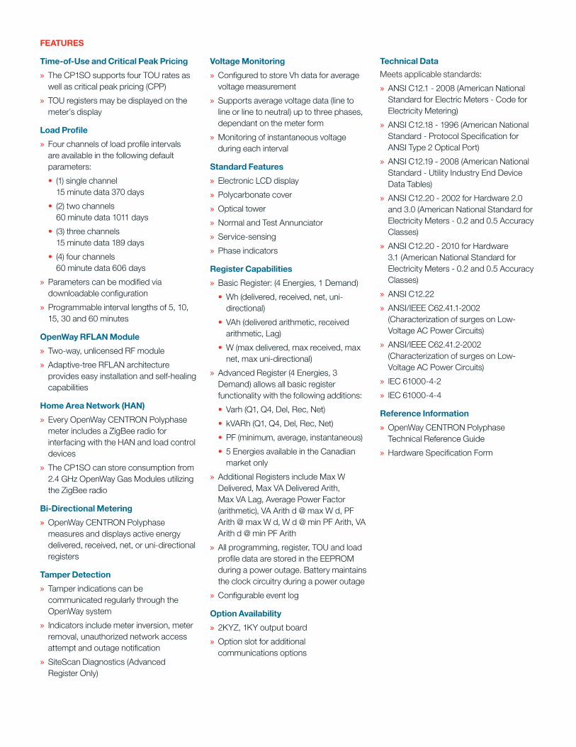
Time-of-use and Critical Peak Pricing
» The CP1SO supports four TOU rates as well as critical peak pricing (CPP)
» TOU registers may be displayed on the meter’s display
Load Profile
» Four channels of load profile intervals are available in the following default parameters:
• (1) single channel 15 minute data 370 days
• (2) two channels 60 minute data 1011 days
• (3) three channels 15 minute data 189 days
• (4) four channels 60 minute data 606 days
» Parameters can be modified via downloadable configuration
» Programmable interval lengths of 5, 10, 15, 30 and 60 minutes
OpenWay rFLAN Module
» Two-way, unlicensed RF module
» Adaptive-tree RFLAN architecture provides easy installation and self-healing capabilities
Home Area Network (HAN)
» Every OpenWay CENTRON Polyphase meter includes a ZigBee radio for interfacing with the HAN and load control devices
» The CP1SO can store consumption from 2.4 GHz OpenWay Gas Modules utilizing the ZigBee radio
Bi-Directional Metering
» OpenWay CENTRON Polyphase measures and displays active energy delivered, received, net, or uni-directional registers
Tamper Detection
» Tamper indications can be communicated regularly through the OpenWay system
» Indicators include meter inversion, meter removal, unauthorized network access attempt and outage notification
» SiteScan Diagnostics (Advanced Register Only)
Voltage Monitoring
» Configured to store Vh data for average voltage measurement
» Supports average voltage data (line to line or line to neutral) up to three phases, dependant on the meter form
» Monitoring of instantaneous voltage during each interval
Standard Features
» Electronic LCD display
» Polycarbonate cover
» Optical tower
» Normal and Test Annunciator
» Service-sensing
» Phase indicators
register Capabilities
» Basic Register: (4 Energies, 1 Demand)
•Wh (delivered, received, net, uni-directional)
•VAh (delivered arithmetic, received arithmetic, Lag)
•W (max delivered, max received, max net, max uni-directional)
» Advanced Register (4 Energies, 3 Demand) allows all basic register functionality with the following additions:
•Varh (Q1, Q4, Del, Rec, Net)
• kVARh (Q1, Q4, Del, Rec, Net)
•PF (minimum, average, instantaneous)
• 5 Energies available in the Canadian market only
» Additional Registers include Max W Delivered, Max VA Delivered Arith, Max VA Lag, Average Power Factor (arithmetic), VA Arith d @ max W d, PF Arith @ max W d, W d @ min PF Arith, VA Arith d @ min PF Arith
» All programming, register, TOU and load profile data are stored in the EEPROM during a power outage. Battery maintains the clock circuitry during a power outage
» Configurable event log
Option Availability
» 2KYZ, 1KY output board
» Option slot for additional communications options
Technical Data
Meets applicable standards:
» ANSI C12.1 - 2008 (American National Standard for Electric Meters - Code for Electricity Metering)
» ANSI C12.18 - 1996 (American National Standard - Protocol Specification for ANSI Type 2 Optical Port)
» ANSI C12.19 - 2008 (American National Standard - Utility Industry End Device Data Tables)
» ANSI C12.20 - 2002 for Hardware 2.0 and 3.0 (American National Standard for Electricity Meters - 0.2 and 0.5 Accuracy Classes)
» ANSI C12.20 - 2010 for Hardware 3.1 (American National Standard for Electricity Meters - 0.2 and 0.5 Accuracy Classes)
» ANSI C12.22
» ANSI/IEEE C62.41.1-2002 (Characterization of surges on Low-Voltage AC Power Circuits)
» ANSI/IEEE C62.41.2-2002 (Characterization of surges on Low-Voltage AC Power Circuits)
» IEC 61000-4-2
» IEC 61000-4-4
reference Information
» OpenWay CENTRON Polyphase Technical Reference Guide
» Hardware Specification Form

SPECIFICATIONS
Product Availability Metrology Class Elements Wires Voltage Amps Test
1S1 100 1 2 120-480 15
2S1 200 1.5 3 120-480 30
2S1 320 1.5 3 120-480 50
3S1 20 1 2 120-480 2.5
4S1 20 2 3 120-480 2.5
9S (8S) 20 3 4 120-480 2.5
9S (8S)/36S 20 3 4/3 120-480 2.5
45S/5S 20 2.5 3 120-480 2.5
12S 200 2 3 120-480 30
12S 320 2 3 120-480 50
16S (14S, 15S, 17S) 200 3 4 120-480 30
16S (14S, 15S, 17S) 320 3 4 120-480 501These meter forms are only available in Hardware 3.0
Specifications
Power Requirements
Voltage rating: 120-480 VFrequency: 60 Hz, (50 Hz)Operating voltage: + 20% (60Hz); ± 10% (50 Hz)Operating range: ± 3 HzBattery voltage: 3.6 V nominalBattery operating range: 3.4 V-3.8 VCarryover: 12-year continuous usage or 20-year shelf life
Operating EnvironmentTemperature: -40° to +85°CHumidity: 0% to 95% non-condensing
Transient / Surge SuppressionIEC 61000-4-4-2004-07ANSI C62.45-2002
Accuracy ANSI C12.20 0.2 accuracy class
GeneralDemand interval lengths: Selectable from 5, 6, 10, 12, 15, 20, 30 or 60 min.Demand calculation: Block, sliding, thermal
Energy calculationBasic: KWh (del, rec, net, uni), kVAh (del/rec/net)Advanced: KWh (del, rec, net, uni), kVAh (del, rec, net), kVARh (Q1, Q4, del, rec, net)
TimeLine sync: Power line frequency or Internal CrystalCrystal sync: +0.01% @ 25°C; +0.025% over full temperature range
Display
Nine-digit liquid crystal displaySix-digit data height: 0.4"Annunciator height: 0.088"Display duration: 1-15 secondsThree-digit code number height: 0.24" 3-segment electronic

While Itron strives to make the content of its marketing materials as timely and accurate as possible, Itron makes no claims, promises, or guarantees about the accuracy, completeness, or adequacy of, and expressly disclaims liability for errors and omissions in, such materials. No warranty of any kind, implied, expressed, or statutory, including but not limited to the warranties of non-infringement of third party rights, title, merchantability, and fitness for a particular purpose, is given with respect to the content of these marketing materials. © Copyright 2011, Itron. All rights reserved. 100993SP-04-08/11
Itron is the world’s leading provider of smart metering, data collection and utility software systems, with over 8,000 utilities worldwide relying on our solutions to responsibly and efficiently manage the delivery and use of energy and water. To realize your smarter energy and water future, start here: www.itron.com
ITrON ELECTrIC
313-B North Highway 11 West Union, SC 29696 USA
Phone: 1.877.487.6602 Fax: 1.864.638.4950
COrPOrATE HEADquArTErS
2111 N Molter Road Liberty Lake, WA 99019 USA
Phone: 1.800.635.5461 Fax: 1.509.891.3355
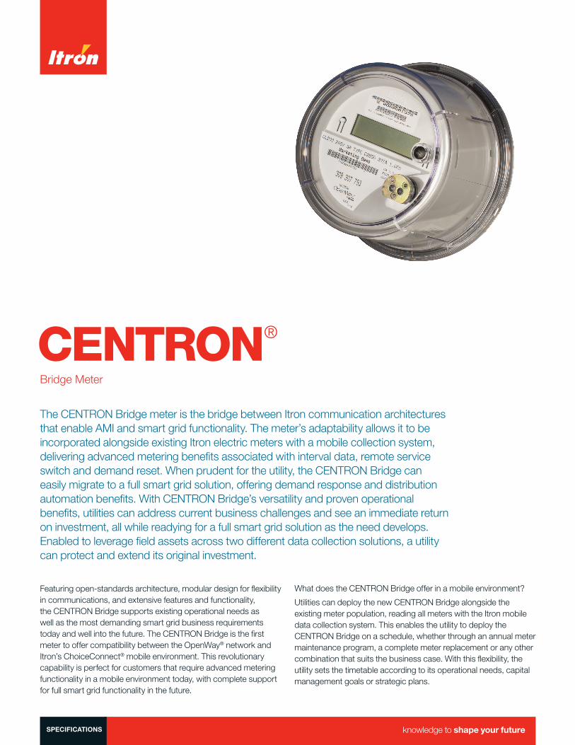
CENTRON®
Bridge Meter
The CENTRON Bridge meter is the bridge between Itron communication architectures that enable AMI and smart grid functionality. The meter’s adaptability allows it to be incorporated alongside existing Itron electric meters with a mobile collection system, delivering advanced metering benefi ts associated with interval data, remote service switch and demand reset. When prudent for the utility, the CENTRON Bridge can easily migrate to a full smart grid solution, offering demand response and distribution automation benefi ts. With CENTRON Bridge’s versatility and proven operational benefi ts, utilities can address current business challenges and see an immediate return on investment, all while readying for a full smart grid solution as the need develops. Enabled to leverage fi eld assets across two different data collection solutions, a utility can protect and extend its original investment.
Featuring open-standards architecture, modular design for fl exibility in communications, and extensive features and functionality, the CENTRON Bridge supports existing operational needs as well as the most demanding smart grid business requirements today and well into the future. The CENTRON Bridge is the fi rst meter to offer compatibility between the OpenWay® network and Itron’s ChoiceConnect® mobile environment. This revolutionary capability is perfect for customers that require advanced metering functionality in a mobile environment today, with complete support for full smart grid functionality in the future.
What does the CENTRON Bridge offer in a mobile environment?
Utilities can deploy the new CENTRON Bridge alongside the existing meter population, reading all meters with the Itron mobile data collection system. This enables the utility to deploy the CENTRON Bridge on a schedule, whether through an annual meter maintenance program, a complete meter replacement or any other combination that suits the business case. With this fl exibility, the utility sets the timetable according to its operational needs, capital management goals or strategic plans.
SPECIFICATIONS

Once deployed, the CENTRON Bridge offers a range of benefi ts. Utilities can streamline current operational processes and subsequently lower costs. Field work required to disconnect meter service is reduced by the ability to activate the under-the-glass service switch in-route with the mobile collection system. Demand reset of commercial meters is also managed with the mobile system, eliminating the need to access the meter or having to worry about setting schedules.
The new CENTRON Bridge also manages and collects up to 40 days of hourly meter data which enable a range of capabilities. With historical usage data, a utility’s customer service department can address bill inquiries in real-time, eliminating the lengthy and costly bill reconciliation process. Customers also gain greater confi dence in the billing process and their bills when questions are answered accurately and in a timely manner.
What does the CENTRON Bridge offer under the OpenWay environment?
While in OpenWay network mode, the meter is fully compliant with the ANSI C12.19 and C12.22 standards for storage and transport of register data. The CENTRON Bridge provides a secure and reliable open-standards approach to data collection and communications between the meter and network.
In addition, each CENTRON Bridge comes factory-equipped with a ZigBee® radio chip to provide a built-in communications pathway into the home for data presentation, load control and demand response. ZigBee also provides a communication channel with 2.4GZ OpenWay gas modules. ZigBee communications can be available regardless of whether the meter is in OpenWay or mobile mode.
The CENTRON Bridge also provides robust data storage capability to support time-of-use pricing, multiple-channel load profi le data and other data-intensive applications, as well as the most advanced feature set available to support smart grid requirements. These features include full two-way communication, a load-limiting remote disconnect and reconnect switch, positive outage detection and restoration notifi cation, voltage monitoring, automatic tamper and theft detection, as well as the ability to reprogram the meter remotely and upload new fi rmware via the network.
The CENTRON Bridge meter is the sensible choice for all your metering needs from mobile data collection to the smart grid.
CHOICECONNECT MOBILE MODE
Energy Values
» One energy register; either kWh delivered, kWh netor kWh unidirectional
» Max demand, cumulative demand, continuous cumulative demand with a remote reset
» One channel of 60-minute interval data with 40 days of data retention
Disconnect/Reconnect service switch operation
» The CENTRON Bridge (forms 1S, 2S, 12S, and 25S) is available with a 200 amp remote disconnect/reconnect switch that can be operated with your ChoiceConnect applications
Tamper Detection
» Tamper indications are included in every communication received by the ChoiceConnect applications
» Tampers include: inversion, removal and reverse power fl ow
» SiteScan Diagnostics™ (advanced polyphase register only, OpenWay Field-Pro™ only)
Other Features
» Ability to schedule a switch from ChoiceConnect to OpenWay mode
» Ability to switch from OpenWay to ChoiceConnect mode
» Time synchronization
» ZigBee radio chip provides access to Consumer Engagement (CE) devices like in-home displays, smart thermostats and others
Security
» ChoiceConnect security deploys end to end security from the mobile communications systems to the meter through authentication of two-way communications and encryptionof meter data
ChoiceConnect Support
» Field Collection System (FCS) w/ MC3, FC200SR or FC300SR
» Field Deployment Manager (FDM) — Endpoint Tools w/ FC200SR, FC300SR or laptop w/ Belt Clip Radio (BCR)
OPENWAY MODE
Time-of-Use and Critical Peak Pricing (CPP)
» The CENTRON Bridge supports four TOU rates as well as CPP
» TOU registers may be shown on the meter’s display
Load Profi le
» Four channels of confi gurable load profi le data are available in the following default parameters:
• single channel, 30-minute data; 753 days
• two channels, 30-minute data; 501 days
» Modifi ed parameters are available via confi guration download
» The CENTRON Bridge module provides over one year of 15-minute load profi le data storage
OpenWay RFLAN Range Extender Module
» Two-way, unlicensed RF module
» Adaptive-tree RFLAN architecture provides easy installation and self-healing capabilities
Home Area Network (HAN)
» Every CENTRON Bridge meter includes a ZigBee radio for interfacing with the HAN, in-home displays and load control devices
» The CENTRON Bridge can store consumption from 2.4GZ OpenWay gas modules utilizing the ZigBee radio
Bi-Directional Metering
» The CENTRON Bridge measures and displays active energy (kWh) delivered and/or received, uni-directional and/or net or apparent energy (kVAh) delivered and/or received
Disconnect/Reconnect with Load Limiting
» The CENTRON Bridge (forms 1S, 2S, 12S, and 25S) is available with a 200 amp remote disconnect/reconnect switch as an optional feature. Utilizing this switch, the meter can be programmed as service limiting
Tamper Detection
» Tamper indications can be communicated regularly through the OpenWay system
» Tampers include: inversion, removal and reverse power fl ow
» SiteScan Diagnostics (advanced polyphase register only)
Non-Volatile Memory
» All programming, register, TOU and load profi le data are stored in the electrically erasable programmable read-only memory (EEPROM) during a power outage. A battery maintains just the clock circuitry during a power outage
Voltage Monitoring
» Instantaneous voltage
» Voltage monitoring system
Register Capabilities
» Four energies, one demand:
• Wh (delivered, received, net, uni-directional)
• VAh (delivered arithmetic, received arithmetic, lag)
• W (max delivered, max received, max net, max uni-directional)
» Confi gurable event log
» All programming, register, TOU and load profi le data are stored in the EEPROM during a power outage. Battery maintains the clock circuitry during a power outage
OPTION AVAILABILITY
» Identifi cation/accounting aids
» Remote disconnect/reconnect
» Multiple WAN options including GPRS and ethernet
» Option slot for additional communications options
SPECIFICATIONS
Technical Data
Meets applicable standards:
» ANSI C12.1 - 2001 (American National Standard for Electric Meters - Code for Electricity Metering)
» ANSI C12.18 - 1996 (American National Standard - Protocol Specifi cation for ANSI Type 2 Optical Port)
» ANSI C12.19 - 1997 (American National Standard - Utility Industry End Device Data Tables)
» ANSI C12.20 - 2002 (American National Standard for Electricity Meters-0.2 and 0.5 Accuracy Classes)
» ANSI C12.22 - (consult ANSI electricity metering protocol standards, balloted version)
» ANSI/IEEE C62.45 - 1992 (Guide to Surge Testing on Low-Voltage AC Power Circuits)
» IEC 61000-4-2
» IEC 61000-4-4
Reference Information
» OpenWay CENTRON Technical Reference Guide
» Hardware Specifi cation Form

While Itron strives to make the content of its marketing materials as timely and accurate as possible, Itron makes no claims, promises, or guarantees about the accuracy, completeness, or adequacy of, and expressly disclaims liability for errors and omissions in, such materials. No warranty of any kind, implied, expressed, or statutory, including but not limited to the warranties of non-infringement of third party rights, title, merchantability, and fitness for a particular purpose, is given with respect to the content of these marketing materials. © Copyright 2013, Itron. All rights reserved. 101222SP-02 01/14
Itron is a world-leading technology and services company dedicated to the resourceful use of energy and water. We provide comprehensive solutions that measure, manage and analyze energy and water. Our broad product portfolio includes electricity, gas, water and thermal energy measurement devices and control technology; communications systems; software; as well as managed and consulting services. With thousands of employees supporting nearly 8,000 customers in more than 100 countries, Itron applies knowledge and technology to better manage energy and water resources.
Together, we can create a more resourceful world. Join us: www.itron.com.
CORPORATE HEADQUARTERS2111 N Molter RoadLiberty Lake, WA 99019USA
Phone: 1.800.635.5461Fax: 1.509.891.3355


![PA Smart · PDF fileEnergy Gateways Programmable ... Meter, Thermostat, or In-Home Gatewayyg Bridge. ... Microsoft PowerPoint - PA Smart Metering.ppt [Compatibility Mode]](https://img.pdfslide.net/doc/110x75/5a79fbf97f8b9a3f618bf8c2/pa-smart-gateways-programmable-meter-thermostat-or-in-home-gatewayyg-bridge.jpg)


![Untitled-4 [] · Standard lamineret (8 meter / *4 meter) Neon lamineret - 5 meter Mat lamineret - 8 meter / **5 meter) Metallic lamineret - 8 meter Ulamineret - 8 meter Fleksibel](https://img.pdfslide.net/doc/110x75/5f3a768af7b8e86a6437cff7/untitled-4-standard-lamineret-8-meter-4-meter-neon-lamineret-5-meter.jpg)