Embed Size (px)
Citation preview

CENTURY SERIES
OWNER'S MANUAL
LM

Congratulations on your purchase of a Century Series console. All of us at Crest Audio in Paramus, NewJersey, USA, support your decision, knowing your console contains the finest combination of design andmanufacture in the industry.
While your new Century Series console is one of the most feature-packed available, great effort has beenput into making it simple to operate.
This manual explains the functions of your new console, how they operate and how they relate to eachother. If properly cared for, your new console will provide you with trouble-free, sonically accurate mixingclear into the next Century and beyond.
Please keep the following contact information on hand:
Crest Audio Customer Service Dept.100 Eisenhower Drive
Paramus NJ 07652 USATEL 201.909.8700 FAX 201.909.8744
http://www.crestaudio.com
Crest Audio Inc.100 Eisenhower Dr., Paramus NJ 07652 USA
TEL: 201.909.8700 FAX: 201.909.8744http://www.crestaudio.com
Printed in USA
Feature Overview 2A brief description of the LM design, features and functions.
System Connections 3Contains diagrams illustrating conventional system connections.
Wiring Conventions 5Contains diagrams indicating how connectors for Crest consoles are wired.
Power Supply 6A description of the rack-mountable Century Series consoles power supply.
Power Connections 7A description of Crest console power connections.
Console Cooling 7A brief description of the dual-fan cooling setup.
LM-12 Input Module 8Profiles the LM-12 input module. The module is illustrated and described.
LM-20 (LM-8+4) Input Module 10Profiles the LM-20 (LM-8+4) input module. The module is illustrated and described.
LM-12 Output Module 13Profiles the LM-12 ouput module. The module is illustrated and described.
LM 8+4 Output Module 15Profiles the LM-8+4 output module. The module is illustrated and described.
LM-20 Output Module 17Profiles the LM-20 ouput module. The module is illustrated and described.
Master Module A 19Profiles the LM A-Master module. The module is illustrated and described.
Master Module B 21Profiles the LM B-Master module. The module is illustrated and described.
Technical Information Appendix AIncludes dimensions, specifications, console access details,user options, console block diagram, and rear panel layout.
Glossary Appendix BThe specific details of console operation are described here, alphabetically.
Schematics Appendix CThis appendix lists available LM console & power supply schematics.
PAGE 1
LM
LM
LM
LM
LM
LM
LM
LM
LM
LM
LM
LM
LM
LM
LM
LM
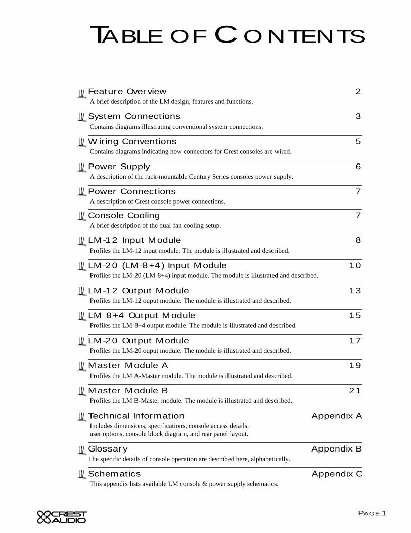
TABLE OF CONTENTS
LM
PAGE 2
CENTURY SERIES
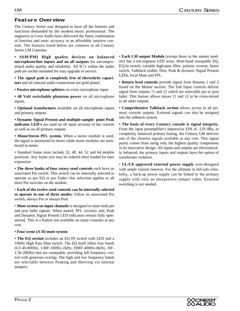
Feature OverviewThe Century Series was designed to have all the features andfunctions demanded by the modern music professional. Theengineers at Crest Audio have delivered the finest combinationof function and sonic accuracy in an affordable intuitive con-sole. The features listed below are common to all CenturySeries LM Consoles.
• SSM/PMI High quality devices on balancedmicrophone/line inputs and on all outputs for uncompro-mised audio quality and reliability. All IC’s within the audiopath are socket mounted for easy upgrade or service.
• The signal path is completely free of electrolytic capaci-tors and all internal audio connections are gold plated.
• Passive microphone splitters on every microphone input.
• 48 Volt switchable phantom power on all microphoneinputs.
• Optional transformers available on all microphone inputsand primary outputs.
• Dynamic Signal Present and multiple-sample- point Peakindicator LED’s are used on all input sections of the consoleas well as on all primary outputs.
• Mono/Stereo PFL system. When a stereo module is used,the signal is monitored in stereo while mono modules are mon-itored in mono.
• Standard frame sizes include 32, 40, 44, 52 and 64 modulepositions. Any frame size may be ordered short loaded for laterexpansion.
• The three banks of four rotary send controls each have anassociated Pre switch. This switch can be internally selected tooperate as pre EQ or pre Fader; this selection applies to allthree Pre switches on the module.
• Each of the twelve send controls can be internally selectedto operate in one of three modes: follow its associated Preswitch, always Pre or always Post.
• Mute system on input channels is designed to mute both preand post fader signals. When muted, PFL circuitry and, Peakand Dynamic Signal Present LED indicators remain fully oper-ational. This is a feature not available on many consoles at anycost.
• Four scene (A-D) mute system
• The EQ section includes an EQ IN switch with LED and a100Hz High Pass filter switch. The EQ itself offers four bands(LF-40-800Hz, LMF-100Hz-2kHz, HMF-400Hz-8kHz, HF-1.5k-20kHz) that are sweepable, providing full frequency con-trol with generous overlap. The high and low frequency bandsare selectable between Peaking and Shelving via internaljumpers.
• Each LM output Module (except those in the master mod-ule) has a ten-segment LED array, three-band sweepable EQ,EQ-In switch, variable high-pass filter, polarity reverse, Insertswitch, Talkback enable, Dim, Peak & dynamic Signal PresentLEDs, local Mute and PFL.
• Return level controls provide signal from Returns 1 and 2found on the Master section. The Sub Input controls deliversignal from outputs 11 and 12 which are selectable pre or postfader. This feature allows mixes 11 and 12 to be cross-mixedto all other outputs.
• Comprehensive Talkback section allows access to all pri-mary console outputs. External signals can also be assignedinto the talkback system.
• The basis of every Century console is signal integrity.From the input preamplifier's impressive EIN of -129 dBu, tocompletely balanced primary busing, the Century LM deliversone of the cleanest signals available at any cost. This signalpurity comes from using only the highest quality componentsin its innovative design. All inputs and outputs are electronical-ly balanced, the primary inputs and outputs have the option oftransformer isolation.
• UL/CE-approved external power supply over-designedwith ample current reserves. For the ultimate in fail-safe relia-bility, a back-up power supply can be linked to the primarysupply with only an inexpensive jumper cable. Externalswitching is not needed.
LIVE MONITOR CONSOLE
PAGE 3
CENTURY SERIES LM
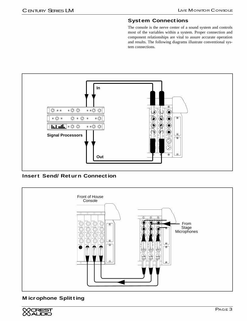
System ConnectionsThe console is the nerve center of a sound system and controlsmost of the variables within a system. Proper connection andcomponent relationships are vital to assure accurate operationand results. The following diagrams illustrate conventional sys-tem connections.
Signal Processors
In
Out
BAL INSERT RTN
DIR OUT
INSERT SEND
BAL MIC IN
BAL LINE IN
BAL INSERT RTN
DIR OUT
INSERT SEND
BAL MIC IN
BAL LINE IN
BAL INSERT RTN
DIR OUT
INSERT SEND
BAL MIC IN
BAL LINE IN
BAL INSERT RTN
DIR OUT
INSERT SEND
BAL MIC IN
BAL LINE IN
Front of HouseConsole
FromStage
Microphones
Insert Send/Return Connection
Microphone Splitting
LM
PAGE 4
CENTURY SERIES
Clip/Limit
Signal
Temp/DC
Active
Ch B
-1
0dB
-3-6
-10
-15
-30
-80
6001 Professional Power Amplifier
Ch A
-1
0dB
-3-6
-10
-15
-30
-80
Clip/Limit
Signal
Temp/DC
Active
Ch B
-1
0dB
-3-6
-10
-15
-30
-80
6001 Professional Power Amplifier
Ch A
-1
0dB
-3-6
-10
-15
-30
-80
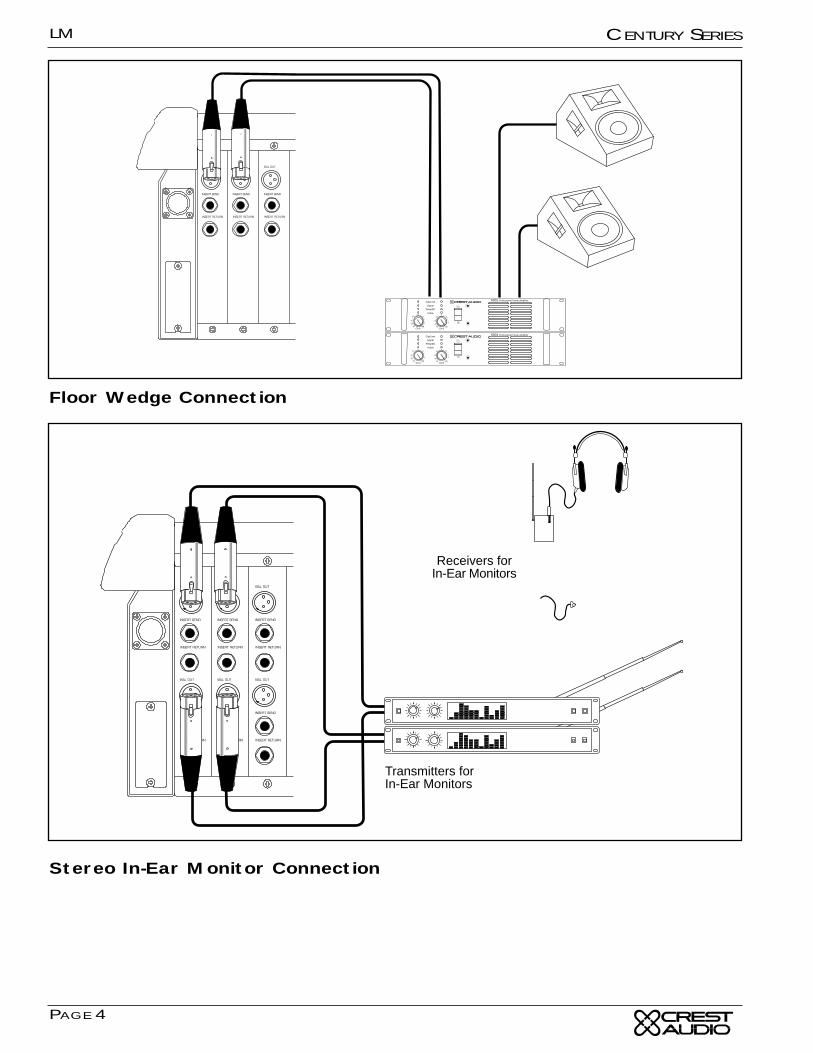
Transmitters forIn-Ear Monitors
Receivers forIn-Ear Monitors
Floor Wedge Connection
Stereo In-Ear Monitor Connection
LM
PAGE 5
CENTURY SERIES
12
3
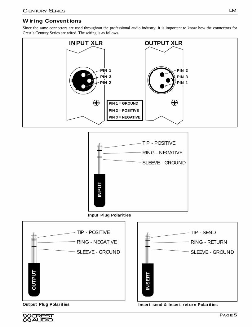
PIN 1 = GROUND
PIN 2 = POSITIVE
PIN 3 = NEGATIVE
OUTPUT XLRINPUT XLR
PIN 3
PIN 1
PIN 2PIN 3
PIN 2
PIN 1
TIP - POSITIVE
RING - NEGATIVE
SLEEVE - GROUND
INPU
T
TIP - SEND
RING - RETURN
SLEEVE - GROUND
INSER
T
TIP - POSITIVE
RING - NEGATIVE
SLEEVE - GROUND
OU
TPU
T
Input Plug Polarities
Insert send & Insert return PolaritiesOutput Plug Polarities
Wiring ConventionsSince the same connectors are used throughout the professional audio industry, it is important to know how the connectors forCrest’s Century Series are wired. The wiring is as follows.
LM
PAGE 6
CENTURY SERIES
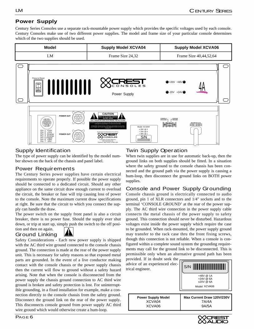
Power SupplyCentury Series Consoles use a separate rack-mountable power supply which provides the specific voltages used by each console.Century Consoles make use of two different power supplies. The model and frame size of your particular console determineswhich of the two supplies should be used.
Model
LM
Supply Model XCVA04
Frame Size 24,32
Supply Model XCVA06
Frame Size 40,44,52,64
Power Supply
C O N S O L E S
+20V
-20V
+48V
+24V
Press to Reset
4AON
Designed & manufactured in the USA by:
A division of Crest Audio Inc.100 Eisenhower Dr.
Paramus, New Jersey 07652 USA
POWER OUT
POWER OUT
RISK OF ELECTRIC SHOCKDO NOT OPEN
CAUTION
AVIS : RISQUE DE CHOC ÉLECTRIQUE—NE PAS OUVRIR
WARNING TO REDUCE THE RISK OF FIRE OR ELECTRIC SHOCK DO NOTEXPOSE THIS EQUIPMENT TO RAIN OR MOISTURE.
ATTENTION! POUR ÉVITER LE RISQUE D'INCENDIE OU DE CHOCÉLECTRIQUE, NE PLACEZ PAS CET APPAREIL SOUS LA PLUIE OU Á
L'HUMIDITÉ
67
2 145 3
Pin 1 +24VPin 2 +20VPin 3 AnalogPin 4 AnalogPin 5 DigitalPin 6 +48VPin 7 -20V
CONSOLEGROUND
CHASSISGROUND
MAXIMUM AC IN:XCVA04: 415 WATTSXCVA06: 825 WATTS
+ 48V @ 1+ 24V @ 6± 20V @ 6
Model XCVA06
Model XCVA04± 20V @ 4+ 24V @ 4
S/N
Supply IdentificationThe type of power supply can be identified by the model num-ber shown on the back of the chassis and panel label.
Power RequirementsThe Century Series power supplies have certain electricalrequirements to operate properly. If possible the power supplyshould be connected to a dedicated circuit. Should any otherappliance on the same circuit draw enough current to overloadthe circuit, the breaker or fuse will trip causing loss of powerto the console. Note the maximum current draw specificationsat right. Be sure that the circuit to which you connect the sup-ply can handle the draw. The power switch on the supply front panel is also a circuitbreaker, there is no power fuse. Should the supply ever shutdown, or trip at start up, simply push the switch to the off posi-tion and then on again.
Ground LinkingSafety Considerations - Each new power supply is shippedwith the AC third wire ground connected to the console chassisground. The connection is made at the rear of the power supplyunit. This is necessary for safety reasons so that exposed metalparts are grounded. In the event of a live conductor makingcontact with the console chassis or the power supply chassisthen the current will flow to ground without a safety hazardarising. Note that when the console is disconnected from thepower supply the chassis ground connection to AC third wireground is broken and safety protection is lost. For uninterrupt-ible grounding, in a fixed installation for example, make a con-nection directly to the console chassis from the safety ground.Disconnect the ground link on the rear of the power supply.This disconnects console ground from power supply AC thirdwire ground which would otherwise create a hum-loop.
Twin Supply OperationWhen twin supplies are in use for automatic back-up, then theground links on both supplies should be fitted. In a situationwhere the safety ground to the console chassis has been con-nected and the ground path via the power supply is causing ahum-loop, then disconnect the ground links on BOTH powersupplies.
Console and Power Supply GroundingConsole chassis ground is electrically connected to audioground, pin 1 of XLR connectors and 1/4" sockets and to theterminal ‘CONSOLE GROUND’ at the rear of the power sup-ply. The AC third wire connection in the power supply cableconnects the metal chassis of the power supply to safetyground. This connection should never be disturbed. Hazardousvoltages exist inside the power supply which require the caseto be grounded. When rack-mounted, the power supply groundmay transfer to the rack case thru the front fixing screws,though this connection is not reliable. When a console is con-figured within a complete sound system the grounding require-ments may call for the ground link to be disconnected. This ispermissible only when an alternative ground path has beenprovided. If in doubt seek theadvice of an experienced elec-trical engineer.
+48V @ 1A+24V @ 6A±20V @ 6A
Model XCVA06
Model XCPS-40±20V @ 4+24V @ 4
S/N
Power Supply ModelXCVA04XCVA06
Max Current Draw 120V/230V7A/4A9A/5A
LM
PAGE 7
CENTURY SERIES
Designed & manufactured in the USA by:
A division of Crest Audio Inc.100 Eisenhower Dr.
Paramus, New Jersey 07652 USA
POWER OUT
POWER OUT
RISK OF ELECTRIC SHOCKDO NOT OPEN
CAUTION
AVIS : RISQUE DE CHOC ÉLECTRIQUE—NE PAS OUVRIR
WARNING TO REDUCE THE RISK OF FIRE OR ELECTRIC SHOCK DO NOTEXPOSE THIS EQUIPMENT TO RAIN OR MOISTURE.
ATTENTION! POUR ÉVITER LE RISQUE D'INCENDIE OU DE CHOCÉLECTRIQUE, NE PLACEZ PAS CET APPAREIL SOUS LA PLUIE OU Á
L'HUMIDITÉ
67
2 145 3
Pin 1 +24VPin 2 +20VPin 3 AnalogPin 4 AnalogPin 5 DigitalPin 6 +48VPin 7 -20V
CONSOLEGROUND
CHASSISGROUND
MAXIMUM AC IN:XCVA04: 415 WATTSXCVA06: 825 WATTS
+ 48V @ 1+ 24V @ 6± 20V @ 6
Model XCVA06
Model XCVA04± 20V @ 4+ 24V @ 4
S/N
To AC Mains
To AC Mains
Interface Cable
To Console
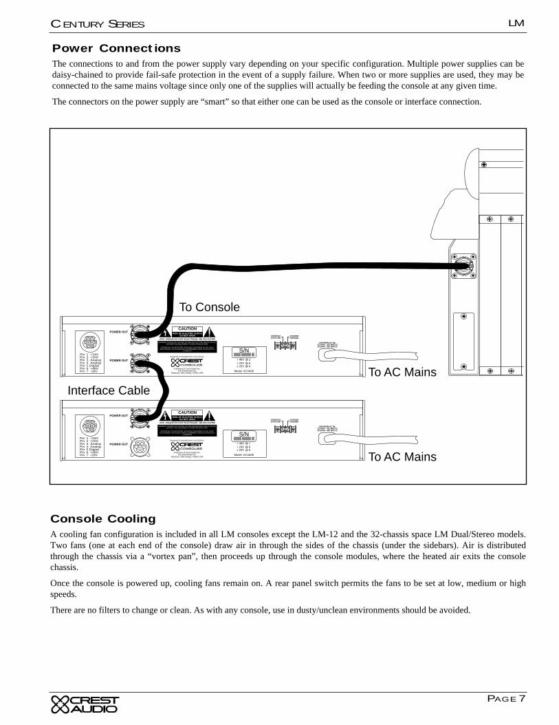
Power ConnectionsThe connections to and from the power supply vary depending on your specific configuration. Multiple power supplies can bedaisy-chained to provide fail-safe protection in the event of a supply failure. When two or more supplies are used, they may beconnected to the same mains voltage since only one of the supplies will actually be feeding the console at any given time.
The connectors on the power supply are “smart” so that either one can be used as the console or interface connection.
Console CoolingA cooling fan configuration is included in all LM consoles except the LM-12 and the 32-chassis space LM Dual/Stereo models.Two fans (one at each end of the console) draw air in through the sides of the chassis (under the sidebars). Air is distributedthrough the chassis via a “vortex pan”, then proceeds up through the console modules, where the heated air exits the consolechassis.
Once the console is powered up, cooling fans remain on. A rear panel switch permits the fans to be set at low, medium or highspeeds.
There are no filters to change or clean. As with any console, use in dusty/unclean environments should be avoided.
LM
PAGE 8
CENTURY SERIES
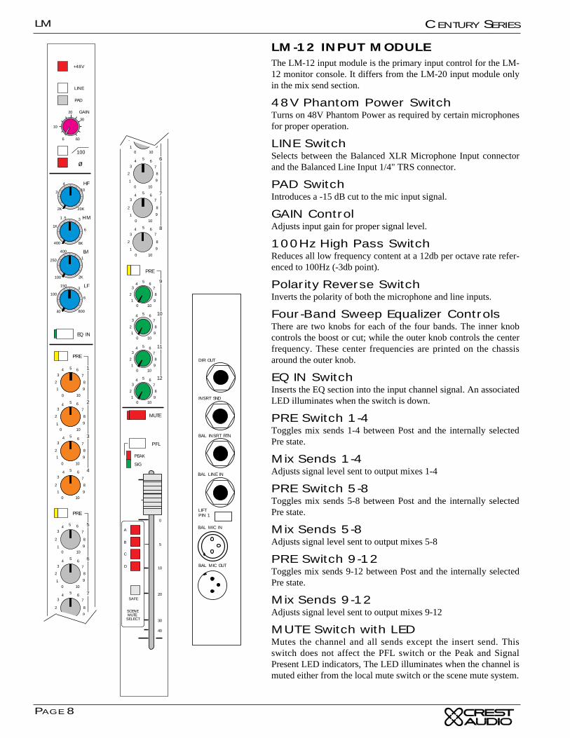
LM-12 INPUT MODULE The LM-12 input module is the primary input control for the LM-12 monitor console. It differs from the LM-20 input module onlyin the mix send section.
48V Phantom Power SwitchTurns on 48V Phantom Power as required by certain microphonesfor proper operation.
LINE SwitchSelects between the Balanced XLR Microphone Input connectorand the Balanced Line Input 1/4" TRS connector.
PAD SwitchIntroduces a -15 dB cut to the mic input signal.
GAIN ControlAdjusts input gain for proper signal level.
100Hz High Pass SwitchReduces all low frequency content at a 12db per octave rate refer-enced to 100Hz (-3db point).
Polarity Reverse SwitchInverts the polarity of both the microphone and line inputs.
Four-Band Sweep Equalizer ControlsThere are two knobs for each of the four bands. The inner knobcontrols the boost or cut; while the outer knob controls the centerfrequency. These center frequencies are printed on the chassisaround the outer knob.
EQ IN SwitchInserts the EQ section into the input channel signal. An associatedLED illuminates when the switch is down.
PRE Switch 1-4Toggles mix sends 1-4 between Post and the internally selectedPre state.
Mix Sends 1-4Adjusts signal level sent to output mixes 1-4
PRE Switch 5-8Toggles mix sends 5-8 between Post and the internally selectedPre state.
Mix Sends 5-8Adjusts signal level sent to output mixes 5-8
PRE Switch 9-12Toggles mix sends 9-12 between Post and the internally selectedPre state.
Mix Sends 9-12Adjusts signal level sent to output mixes 9-12
MUTE Switch with LEDMutes the channel and all sends except the insert send. Thisswitch does not affect the PFL switch or the Peak and SignalPresent LED indicators, The LED illuminates when the channel ismuted either from the local mute switch or the scene mute system.
20
10
6
30
60
100
40
1503
6
800
250
100
400
1
2K
1K
400
1.5 3
6
8K
3
2K
4
10
20K
+48V
100
EQ IN
HM
LM
PAD
LF
GAIN
HF
PRE
PRE
PRE
7
8
9
5
2
1
34 6
7
8
9
5
2
01
34 6
10
7
8
9
5
2
01
34 6
10
7
8
9
5
2
01
34 6
10
7
8
9
5
2
01
34 6
10
7
8
9
5
2
01
34 6
10
7
8
9
5
2
0
1
34 6
10
7
8
9
5
2
01
34 6
10
7
8
9
5
2
0
1
34 6
10
LINE
ø
5
6
7
8
1
2
3
4
9
MUTE
PFL
PEAK
SIG
0
5
10
30
40
20
PRE
PRE
7
8
9
5
2
01
34 6
10
7
8
9
5
2
01
34 6
10
7
8
9
5
2
01
34 6
10
7
8
9
5
2
01
34 6
10
7
8
9
5
2
01
34 6
10
7
8
9
5
2
01
34 6
10
7
8
9
5
2
01
34 6
10
7
8
9
5
2
01
34 6
10
7
8
9
2
0
1
3
10
SCENEMUTE
SELECT
A
B
C
D
SAFE
7
8
9
5
2
01
34 6
10
5
6
7
8
4
9
10
11
12
BAL INSRT RTN
DIR OUT
INSRT SND
BAL MIC IN
BAL MIC OUT
PIN 1LIFT
BAL LINE IN
LM
PAGE 9
CENTURY SERIES
PFL SwitchSamples the channel’s signal pre-fader and allows for monitor-ing within the master section of the console. This signal is notaffected by the Mute Switch. When depressed, the signal levelcan be seen on the output 12 meter, and heard via the mixer’sheadphone or local monitor output. When this PFL Switch isdepressed, the channel PEAK LED indicator illuminates at alower intensity. When used as a status indicator of switch posi-tion, the Peak LED indicating circuit remains fully operationalby illuminating at a much higher intensity than when indicat-ing PFL status.
PEAK LED IndicatorIlluminates RED when any of the points monitored come with-in 3db of the clipping point. Signal is sampled after the inputpreamplifier stage, after the EQ section, and after the fader.
This LED also serves as a PFL ON indicator, but at a muchlower intensity than when it is used to indicate clipping.
SIGNAL PRESENT LEDThis green LED constantly displays level activity of the inputchannel by varying in intensity.
100mm FaderUsed for control of all outputs of the channel except thosesends selected pre fader. (The Insert Output level is not affect-ed by the fader position.)
Scene Mute AssignmentsAssign the input channel to any of the four scene mute groups.Scene mute combines with the module’s local mute button, andactuates the local mute LED.
Scene Mute Safe SwitchDisables any selected scene mute assignments. An associatedgreen LED indicates that the channel is in a safe state.
Rear Panel ConnectionsDirect OutThis 1/4-inch TRS jack carries the direct output signal (postfader & post mute) from the associated input channel.
Insert SendThis 1/4-inch TRS jack carries the send signal of the insertloop to the external effect or signal processor.
Balanced Insert ReturnThis 1/4-inch TRS jack accepts the return signal of the insertloop from the external effect or signal processor back into theconsole.
Balanced Line InThis 1/4-inch TRS jack accepts balanced and unbalanced linelevel inputs and delivers it into the associated input channel.
Lift Pin 1This ground lift switch may be used to isolate pin1 of the micXLR from console ground.
Unpressed = pin 1 grounded
Pressed = pin 1 lifted
Balanced Mic InThis XLR connector accepts balanced microphone inputs forthe associated input channel.
Balanced Mic OutThis XLR connector is in parallel with the Balanced Mic Inconnector and allows easy connection of the monitor board tothe FOH console.
LM
PAGE 10
CENTURY SERIES
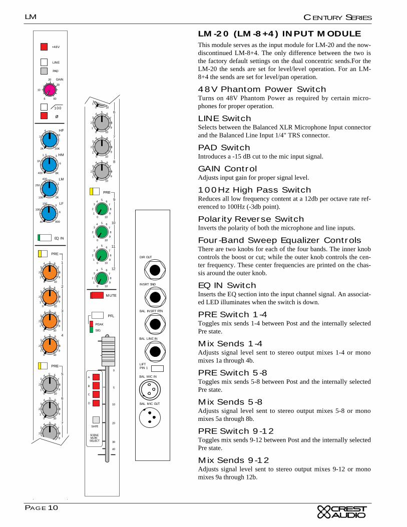
LM-20 (LM-8+4) INPUT MODULEThis module serves as the input module for LM-20 and the now-discontinued LM-8+4. The only difference between the two isthe factory default settings on the dual concentric sends.For theLM-20 the sends are set for level/level operation. For an LM-8+4 the sends are set for level/pan operation.
48V Phantom Power SwitchTurns on 48V Phantom Power as required by certain micro-phones for proper operation.
LINE SwitchSelects between the Balanced XLR Microphone Input connectorand the Balanced Line Input 1/4" TRS connector.
PAD SwitchIntroduces a -15 dB cut to the mic input signal.
GAIN ControlAdjusts input gain for proper signal level.
100Hz High Pass SwitchReduces all low frequency content at a 12db per octave rate ref-erenced to 100Hz (-3db point).
Polarity Reverse SwitchInverts the polarity of both the microphone and line inputs.
Four-Band Sweep Equalizer ControlsThere are two knobs for each of the four bands. The inner knobcontrols the boost or cut; while the outer knob controls the cen-ter frequency. These center frequencies are printed on the chas-sis around the outer knob.
EQ IN SwitchInserts the EQ section into the input channel signal. An associat-ed LED illuminates when the switch is down.
PRE Switch 1-4Toggles mix sends 1-4 between Post and the internally selectedPre state.
Mix Sends 1-4Adjusts signal level sent to stereo output mixes 1-4 or monomixes 1a through 4b.
PRE Switch 5-8Toggles mix sends 5-8 between Post and the internally selectedPre state.
Mix Sends 5-8Adjusts signal level sent to stereo output mixes 5-8 or monomixes 5a through 8b.
PRE Switch 9-12Toggles mix sends 9-12 between Post and the internally selectedPre state.
Mix Sends 9-12Adjusts signal level sent to stereo output mixes 9-12 or monomixes 9a through 12b.
20
10
6
30
60
100
40
1503
6
800
250
100
400
1
2K
1K
400
1.5 3
6
8K
3
2K
4
10
20K
+48V
100
EQ IN
HM
LM
PAD
LF
GAIN
HF
PRE
PRE
4
PRE
7
8
9
5
2
1
34 6
7
8
9
5
2
01
34 6
10
7
8
9
5
2
01
34 6
10
7
8
9
5
2
01
34 6
10
7
8
9
5
2
01
34 6
10
7
8
9
5
2
01
34 6
10
7
8
9
5
2
0
1
34 6
10
7
8
9
5
2
01
34 6
10
7
8
9
5
2
0
1
34 6
10
LINE
ø
2
3
1
5
6
7
8
9
MUTE
PFL
PEAK
SIG
0
5
10
30
40
20
PRE
4
PRE
7
8
9
5
2
01
34 6
10
7
8
9
5
2
01
34 6
10
7
8
9
5
2
01
34 6
10
7
8
9
5
2
01
34 6
10
7
8
9
5
2
01
34 6
10
7
8
9
5
2
01
34 6
10
7
8
9
5
2
01
34 6
10
7
8
9
5
2
01
34 6
10
7
8
9
5
2
01
34 6
10
7
8
9
2
0
1
3
10
SCENEMUTE
SELECT
A
B
C
D
SAFE
5
6
7
8
9
10
11
12
BAL INSRT RTN
DIR OUT
INSRT SND
BAL MIC IN
BAL MIC OUT
PIN 1LIFT
BAL LINE IN
LM
PAGE 11
CENTURY SERIES
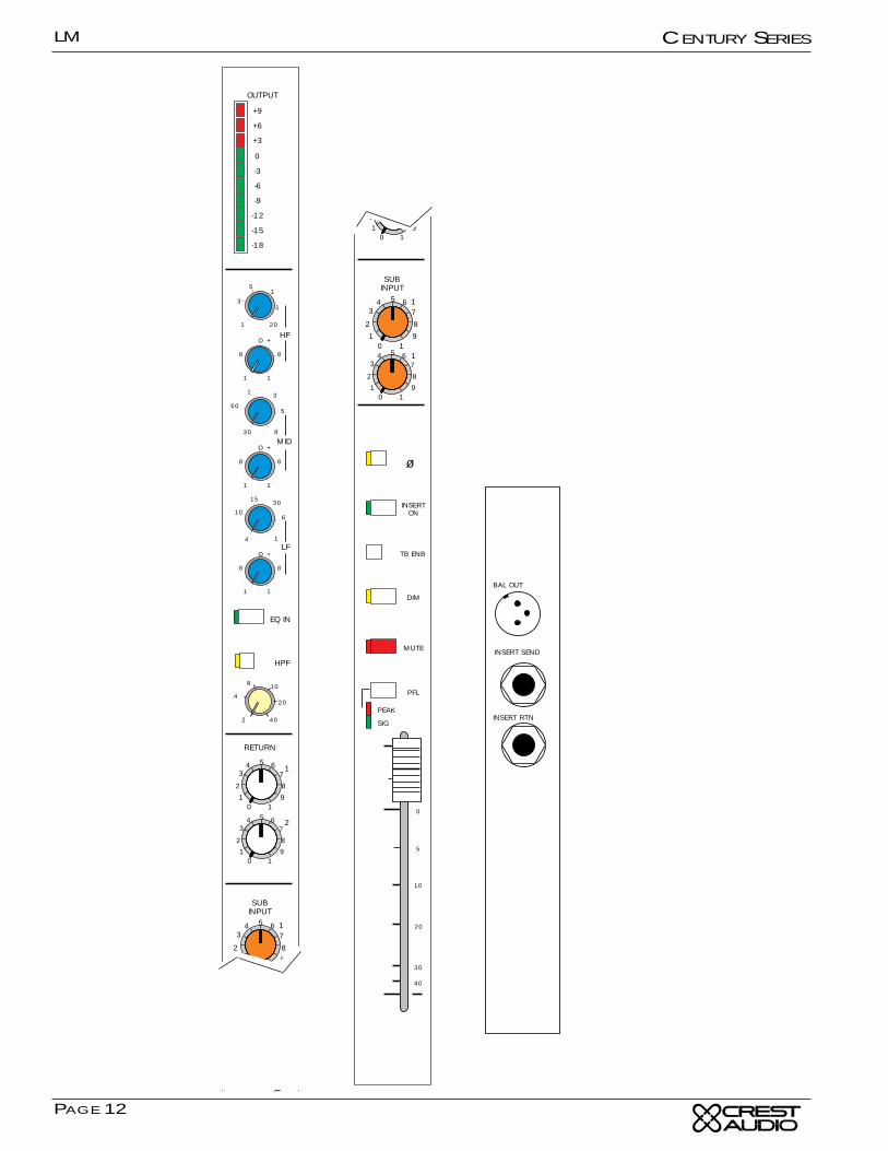
MUTE Switch with LEDMutes the channel and all sends. This switch does not affectthe PFL switch or the Peak and Signal Present LED indicators,The LED illuminates when the channel is muted either fromthe local mute switch or the scene mute system.
PFL SwitchSamples the channel’s signal pre-fader and allows for monitor-ing within the master section of the console. This signal is notaffected by the Mute Switch. When depressed, the signal levelcan be seen on the output 12 meter, and heard via the mixer’sheadphone or local monitor output. When this PFL Switch isdepressed, the channel PEAK LED indicator illuminates at alower intensity. When used as a status indicator of switch posi-tion, the Peak LED indicating circuit remains fully operationby illuminating at a much higher intensity than its use as a PFLstatus indicator.
PEAK LED IndicatorIlluminates RED when any of the points monitored come with-in 3db of the clipping point. Signal is sampled after the inputpreamplifier stage, after the EQ section, and after the fader.
This LED also serves as a PFL ON indicator, but at a muchlower intensity than when it is used to indicate clipping.
SIGNAL PRESENT LEDConstantly displays level activity of the input channel by vary-ing in intensity.
100mm FaderUsed for control of all outputs of the channel except those Auxoutput sections selected by switch to a pre fader position. (TheInsert Output level is not affected by the fader position.)
Scene Mute AssignmentsAssign the input channel to any of the four scene mute groups.Scene mute combines with the module’s local mute button, andactuates the local mute LED.
Scene Mute Safe SwitchDisables any selected scene mute assignments. An associatedgreen LED indicates the channel is in a safe state.
Rear Panel ConnectionsDirect OutThis 1/4-inch TRS jack carries the direct output signal (postfader & post mute) from the associated input channel.
Insert SendThis 1/4-inch TRS jack carries the send signal of the insertloop to the external effect or signal processor.
Balanced Insert ReturnThis 1/4-inch TRS jack accepts the return signal of the insertloop from the external effect or signal processor back into theconsole.
Balanced Line InThis 1/4-inch TRS jack accepts balanced and unbalanced linelevel inputs and delivers it into the associated input channel.
Lift Pin 1This ground lift switch may be used to isolate pin1 of the micXLR from console ground.
Unpressed = pin 1 grounded
Pressed = pin 1 lifted
Balanced Mic InThis XLR connector accepts balanced microphone inputs forthe associated input channel.
Balanced Mic OutThis XLR connector is in parallel with the Balanced Mic Inconnector and allows easy connection of the monitor board tothe FOH console.
LM
PAGE 12
CENTURY SERIES
OUTPUT
+9
+6
+3
0
-3
-6
-9
-12
-15
-18
1 1
8 8
O +
1 1
8 8
O +
SUBINPUT
1
1
HF
LF
10
4
15 30
6
1
60
30
1 3
5
8
7
8
9
5
2
01
34 6
1
7
8
9
5
2
01
34 6
1
3
1
51
1
20
1 1
8 8
O +MID
ø
EQ IN
HPF
4
2
8 10
20
40
RETURN
1
2
7
8
9
5
2
01
34 6
1
7
8
9
5
2
01
34 6
1
MUTE
PFL
PEAK
SIG
DIM
TB ENB
INSERTON
SUBINPUT
1
1
1
0
5
10
30
40
5
20
7
8
9
5
2
01
34 6
1
7
8
9
5
2
01
34 6
1
ø
4
2
20
40
RETURN
1
2
7
8
9
5
2
01
34 6
1
7
8
9
5
2
01
34 6
1
BAL OUT
INSERT RTN
INSERT SEND
LM
PAGE 13
CENTURY SERIES
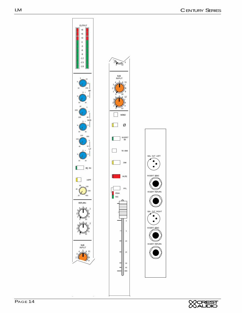
LM-12 Output ModuleThe LM-Mono Group output module is the primary outputmodule on the LM-12 and the secondary output module on theLM-8+4 and the LM-20
Output MeterMonitors the post-fader output signal via a ten-segment LEDarray.
Output EQControls the the equalization of the output mix signal throughthree bands, via six controls. The upper knob of each banddetermines the center frequency (high-1kHz-20kHz, mid-300Hz-8kHz, low-40Hz, 1kHz), while the lower knob adjuststhe amount of boost or cut.
EQ IN SwitchInserts the EQ section into the output channel signal. An asso-ciated LED illuminates when the switch is down.
High Pass Filter SwitchInserts the High Pass Filter into the output signal.
HPF Frequency ControlThis knob adjusts the high pass filter frequency from 20Hz to400Hz. The filter operates at a -12 dB per octave rate.
Return Level ControlsAdjusts the level of return signals 1 and 2 in the output. Thesesignals come from the Master Section. See Returns 1 & 2 onthe Master Section description for more information.
Sub Input ControlsAdjusts the level of cross-mix in the output from mono outputs11 and 12.
Polarity Reverse SwitchInverts the polarity of the output.
Insert On SwitchTurns on the insert loop for the output signal. If a completeinsert loop is not present depressing this switch will mute theoutput.
TB Enable SwitchInjects the talkback signal from the master section into thegroup output.
DIM SwitchIntroduces a -6dB drop to the output signal. This is a pushon/push off switch, not momentary.
MUTE Switch with LEDMutes the output. This switch does not affect the PFL switchor the Peak and Signal Present LED indicators.
Output PFLEnables Pre Fader Listening of the output signal. (this signalcan be internally selected post fader)
Output PEAK & Signal LEDsThe red LED indicates that the output is within 3dB of the clip-ping point.
The green LED constantly displays the level of signal activityby varying in intensity.
Output FaderControls the final output signal level.
Rear Panel ConnectionsBalanced OutThis XLR connector carries the post-fader output signal fromthe associated output module.
Output Insert SendThis 1/4-inch TRS balanced jack carries the send signal of theoutput insert loop to the external effect or signal processor.
Output Insert ReturnThis 1/4-inch TRS balanced jack accepts the return signal ofthe output insert loop from the external effect or signal proces-sor.
LM
PAGE 14
CENTURY SERIES
MONO
OUTPUT
+9
+6
+3
0
-3
-6
-9
-12
-15
-18
16 16
8 8
O +
16 16
8 8
O +
SUBINPUT
11
12
HF
LF
100
40
150 300
6
1K
600
300
1K 3
5
8K
7
8
9
5
2
01
34 6
10
7
8
9
5
2
01
34 6
10
3
1K
5 10
15
20K
16 16
8 8
O +MID
Ø
EQ IN
HPF
40
20
80 100
200
400
RETURN
1
2
7
8
9
5
2
01
34 6
10
7
8
9
5
2
01
34 6
10
MONO
MUTE
PFL
PEAK
SIG
DIM
TB ENB
INSERTON
SUBINPUT
11
12
0
5
10
30
40
5
20
7
8
9
5
2
01
34 6
10
7
8
9
5
2
01
34 6
10
Ø
40
20
100
200
400
RETURN
1
2
7
8
9
5
2
01
34 6
10
7
8
9
5
2
01
34 6
10
INSERT RETURN
BAL OUT LEFT
INSERT SEND
INSERT RETURN
BAL OUT RIGHT
INSERT SEND
LM
PAGE 15
CENTURY SERIES
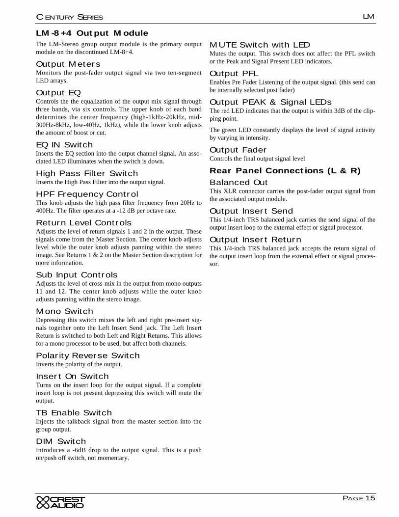
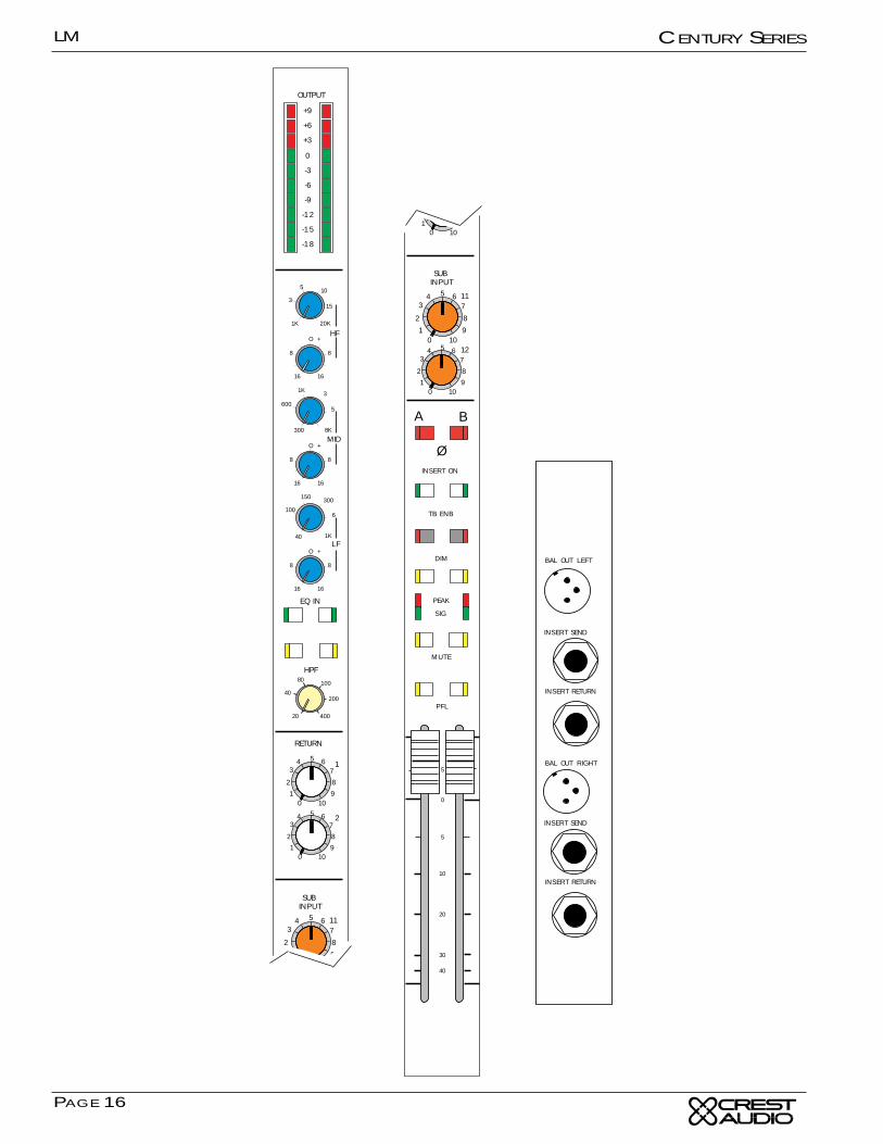
LM-8+4 Output ModuleThe LM-Stereo group output module is the primary outputmodule on the discontinued LM-8+4.
Output MetersMonitors the post-fader output signal via two ten-segmentLED arrays.
Output EQControls the the equalization of the output mix signal throughthree bands, via six controls. The upper knob of each banddetermines the center frequency (high-1kHz-20kHz, mid-300Hz-8kHz, low-40Hz, 1kHz), while the lower knob adjuststhe amount of boost or cut.
EQ IN SwitchInserts the EQ section into the output channel signal. An asso-ciated LED illuminates when the switch is down.
High Pass Filter SwitchInserts the High Pass Filter into the output signal.
HPF Frequency ControlThis knob adjusts the high pass filter frequency from 20Hz to400Hz. The filter operates at a -12 dB per octave rate.
Return Level ControlsAdjusts the level of return signals 1 and 2 in the output. Thesesignals come from the Master Section. The center knob adjustslevel while the outer knob adjusts panning within the stereoimage. See Returns 1 & 2 on the Master Section description formore information.
Sub Input ControlsAdjusts the level of cross-mix in the output from mono outputs11 and 12. The center knob adjusts while the outer knobadjusts panning within the stereo image.
Mono SwitchDepressing this switch mixes the left and right pre-insert sig-nals together onto the Left Insert Send jack. The Left InsertReturn is switched to both Left and Right Returns. This allowsfor a mono processor to be used, but affect both channels.
Polarity Reverse SwitchInverts the polarity of the output.
Insert On SwitchTurns on the insert loop for the output signal. If a completeinsert loop is not present depressing this switch will mute theoutput.
TB Enable SwitchInjects the talkback signal from the master section into thegroup output.
DIM SwitchIntroduces a -6dB drop to the output signal. This is a pushon/push off switch, not momentary.
MUTE Switch with LEDMutes the output. This switch does not affect the PFL switchor the Peak and Signal Present LED indicators.
Output PFLEnables Pre Fader Listening of the output signal. (this send canbe internally selected post fader)
Output PEAK & Signal LEDsThe red LED indicates that the output is within 3dB of the clip-ping point.
The green LED constantly displays the level of signal activityby varying in intensity.
Output FaderControls the final output signal level
Rear Panel Connections (L & R)Balanced OutThis XLR connector carries the post-fader output signal fromthe associated output module.
Output Insert SendThis 1/4-inch TRS balanced jack carries the send signal of theoutput insert loop to the external effect or signal processor.
Output Insert ReturnThis 1/4-inch TRS balanced jack accepts the return signal ofthe output insert loop from the external effect or signal proces-sor.
LM
PAGE 16
CENTURY SERIES
OUTPUT
+9
+6
+3
0
-3
-6
-9
-12
-15
-18
16 16
8 8
O +
16 16
8 8
O +
SUBINPUT
11
12
HF
LF
100
40
150 300
6
1K
600
300
1K 3
5
8K
7
8
9
5
2
01
34 6
10
7
8
9
5
2
01
34 6
10
3
1K
5 10
15
20K
16 16
8 8
O +MID
Ø
EQ IN
HPF
40
20
80 100
200
400
RETURN
1
2
7
8
9
5
2
01
34 6
10
7
8
9
5
2
01
34 6
10
A B
MUTE
PEAK
SIG
DIM
TB ENB
INSERT ON
SUBINPUT
11
127
8
9
5
2
01
34 6
10
7
8
9
5
2
01
34 6
10
Ø
40
20
200
400
RETURN
1
2
7
8
9
5
2
01
34 6
10
7
8
9
5
2
01
34 6
10
A B
PFL
0
5
10
30
40
5
20
INSERT RETURN
BAL OUT LEFT
INSERT SEND
INSERT RETURN
BAL OUT RIGHT
INSERT SEND
LM
PAGE 17
CENTURY SERIES
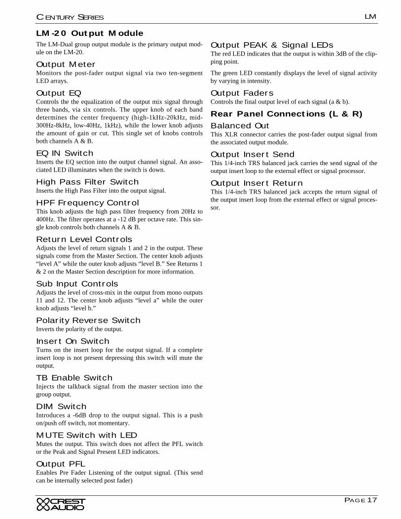
LM-20 Output ModuleThe LM-Dual group output module is the primary output mod-ule on the LM-20.
Output MeterMonitors the post-fader output signal via two ten-segmentLED arrays.
Output EQControls the the equalization of the output mix signal throughthree bands, via six controls. The upper knob of each banddetermines the center frequency (high-1kHz-20kHz, mid-300Hz-8kHz, low-40Hz, 1kHz), while the lower knob adjuststhe amount of gain or cut. This single set of knobs controlsboth channels A & B.
EQ IN SwitchInserts the EQ section into the output channel signal. An asso-ciated LED illuminates when the switch is down.
High Pass Filter SwitchInserts the High Pass Filter into the output signal.
HPF Frequency ControlThis knob adjusts the high pass filter frequency from 20Hz to400Hz. The filter operates at a -12 dB per octave rate. This sin-gle knob controls both channels A & B.
Return Level ControlsAdjusts the level of return signals 1 and 2 in the output. Thesesignals come from the Master Section. The center knob adjusts“level A” while the outer knob adjusts “level B.” See Returns 1& 2 on the Master Section description for more information.
Sub Input ControlsAdjusts the level of cross-mix in the output from mono outputs11 and 12. The center knob adjusts “level a” while the outerknob adjusts “level b.”
Polarity Reverse SwitchInverts the polarity of the output.
Insert On SwitchTurns on the insert loop for the output signal. If a completeinsert loop is not present depressing this switch will mute theoutput.
TB Enable SwitchInjects the talkback signal from the master section into thegroup output.
DIM SwitchIntroduces a -6dB drop to the output signal. This is a pushon/push off switch, not momentary.
MUTE Switch with LEDMutes the output. This switch does not affect the PFL switchor the Peak and Signal Present LED indicators.
Output PFLEnables Pre Fader Listening of the output signal. (This sendcan be internally selected post fader)
Output PEAK & Signal LEDsThe red LED indicates that the output is within 3dB of the clip-ping point.
The green LED constantly displays the level of signal activityby varying in intensity.
Output FadersControls the final output level of each signal (a & b).
Rear Panel Connections (L & R)Balanced OutThis XLR connector carries the post-fader output signal fromthe associated output module.
Output Insert SendThis 1/4-inch TRS balanced jack carries the send signal of theoutput insert loop to the external effect or signal processor.
Output Insert ReturnThis 1/4-inch TRS balanced jack accepts the return signal ofthe output insert loop from the external effect or signal proces-sor.
LM
PAGE 18
CENTURY SERIES
OUTPUT
MONITOR A LEFT
MONITOR A RIGHT
BAL OUT
EXT TB IN
INSERT RTN
INSERT SEND
LM
PAGE 19
CENTURY SERIES
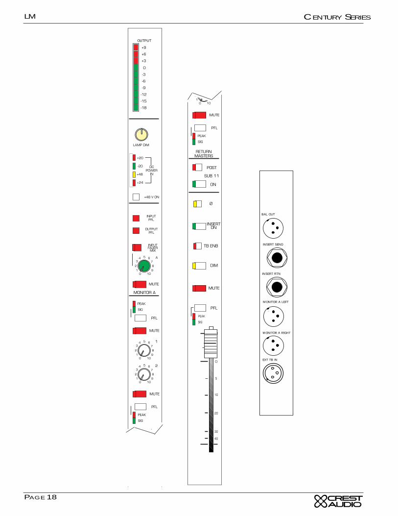
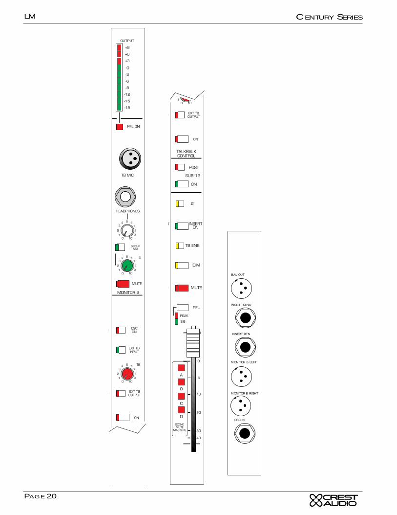
LM Master Module AThis the first of two modules that include master controls forall LM consoles in addition to mono output eleven.
Output MeterMonitors the post-fader output signal of group 11 via a ten-segment LED array.
Monitor Level AAdjusts the output level of local monitors A.
Monitor Mute AMutes local monitor A.
Sub 11 Post SwitchSwitches the subgroup send between pre and post fader.
Sub 11 On SwitchSwitches the subgroup send on and off.
Lamp Dim ControlControls the brightness of any 12 volt lighting devices attachedto the XLR connectors on the light bar.
Power IndicatorsShows the status of the four voltages used by the console.
Phantom Master Switch w/LEDSwitches +48V phantom power on and off for the entire con-sole.
Input/Output PFL IndicatorsThese LEDs indicate what type of signal (input or output) isPFL’d at any given time. Input PFL always gets priority overoutput PFL.
Input Fader Mix SwitchSums all input mixes and assigns the summed signal to theMonitor A output. This output is stereo when stereo signals arepresent. This signal is post fader.
Return Master Peak & Signal LEDsThe red LED indicates that the output is within 3dB of the clip-ping point. The green LED constantly displays the level of sig-nal activity by varying in intensity.
Return Master PFL SwitchPFLs the return signal.
Return Master MuteMutes the return signal
Return Master Level ControlsControls the final return signal level.
Output 11 Polarity Reverse Inverts the polarity of outputs 11.
Output 11 Insert On SwitchTurns on the insert loop for the output signal. If a completeinsert loop is not present depressing this switch will mute theoutput.
Output 11 Talkback Enable Injects the talkback signal from the master section into thegroup output.
Output 11 Dim SwitchIntroduces a -6dB drop to the output signal. This is a pushon/push off switch, not momentary.
Output 11 Mute SwitchMutes the output. This switch does not affect the PFL switchor the Peak and Signal Present LED indicators.
Output 11 PFL SwitchEnables Pre Fader Listening of the output signal. (This can beinternally selected to post fader)
Output 11 Peak & Signal LEDsThe red LED indicates that the output is within 3dB of the clip-ping point. The green LED constantly displays the level of sig-nal activity by varying in intensity.
Output 11 100mm FadersControls the final signal level of outputs 11.
Rear Panel ConnectionsOutput 11 Bal OutThis XLR connector carries the post-fader output signal fromthe output group 11
Insert SendThis 1/4-inch TRS balanced jack carries the send signal of theoutput insert loop to the external effect or signal processor.
Insert ReturnThis 1/4-inch TRS balanced jack accepts the return signal ofthe output insert loop from the external effect or signal proces-sor.
Monitor A Out (L&R)These two connectors deliver local monitor A ‘s balanced out-put signal.
Oscillator / Pink Noise InThis 1/4-inch connector accepts a balanced or unbalanced sig-nal from an oscillator or pink noise generator. This signal isassignable via the talkback assignment switches.
LM
PAGE 20
CENTURY SERIES
OUTPUT
INSERT RTN
MONITOR B LEFT
MONITOR B RIGHT
BAL OUT
OSC IN
INSERT SEND
LM
PAGE 21
CENTURY SERIES
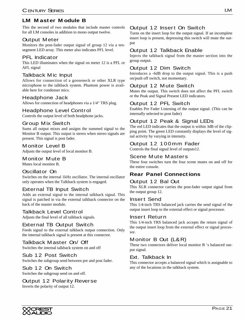
LM Master Module BThis the second of two modules that include master controlsfor all LM consoles in addition to mono output twelve.
Output MeterMonitors the post-fader output signal of group 12 via a ten-segment LED array. This meter also indicates PFL level.
PFL IndicatorThis LED illuminates when the signal on meter 12 is a PFL orAFL signal
Talkback Mic InputAllows for connection of a gooseneck or other XLR typemicrophone to the talkback system. Phantom power is avail-able here for condenser mics.
Headphone JackAllows for connection of headphones via a 1/4" TRS plug.
Headphone Level ControlControls the output level of both headphone jacks.
Group Mix SwitchSums all output mixes and assigns the summed signal to theMonitor B output. This output is stereo when stereo signals arepresent. This signal is post fader.
Monitor Level BAdjusts the output level of local monitor B.
Monitor Mute BMutes local monitor B.
Oscillator OnSwitches on the internal 1kHz oscillator. The internal oscillatoronly operates when the Talkback system is engaged.
External TB Input SwitchAdds an external signal to the internal talkback signal. Thissignal is patched in via the external talkback connector on theback of the master module.
Talkback Level ControlAdjusts the final level of all talkback signals.
External TB Output SwitchFeeds signal to the external talkback output connection. Onlythe internal talkback signal is present at this connector.
Talkback Master On/OffSwitches the internal talkback system on and off
Sub 12 Post SwitchSwitches the subgroup send between pre and post fader.
Sub 12 On SwitchSwitches the subgroup send on and off.
Output 12 Polarity Reverse Inverts the polarity of output 12.
Output 12 Insert On SwitchTurns on the insert loop for the output signal. If an incompleteinsert loop is present, depressing this switch will mute the out-put
Output 12 Talkback Enable Injects the talkback signal from the master section into thegroup output.
Output 12 Dim SwitchIntroduces a -6dB drop to the output signal. This is a pushon/push off switch, not momentary.
Output 12 Mute SwitchMutes the output. This switch does not affect the PFL switchor the Peak and Signal Present LED indicators.
Output 12 PFL SwitchEnables Pre Fader Listening of the output signal. (This can beinternally selected to post fader)
Output 12 Peak & Signal LEDsThe red LED indicates that the output is within 3dB of the clip-ping point. The green LED constantly displays the level of sig-nal activity by varying in intensity.
Output 12 100mm FaderControls the final signal level of outputs12.
Scene Mute MastersThese four switches turn the four scene mutes on and off forthe entire console.
Rear Panel ConnectionsOutput 12 Bal OutThis XLR connector carries the post-fader output signal fromthe output group 12.
Insert SendThis 1/4-inch TRS balanced jack carries the send signal of theoutput insert loop to the external effect or signal processor.
Insert ReturnThis 1/4-inch TRS balanced jack accepts the return signal ofthe output insert loop from the external effect or signal proces-sor.
Monitor B Out (L&R)These two connectors deliver local monitor B ‘s balanced out-put signal.
Ext. Talkback InThis connector accepts a balanced signal which is assignable toany of the locations in the talkback system.


Appendix A
TechnicalInformation
LM
LM
APPENDIX A
CENTURY SERIES
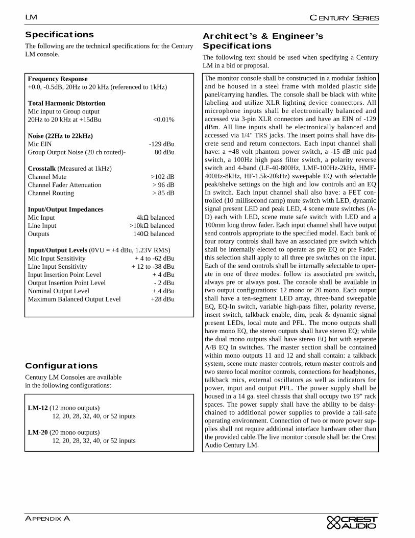
SpecificationsThe following are the technical specifications for the CenturyLM console.
Frequency Response+0.0, -0.5dB, 20Hz to 20 kHz (referenced to 1kHz)
Total Harmonic DistortionMic input to Group output20Hz to 20 kHz at +15dBu <0.01%
Noise (22Hz to 22kHz)Mic EIN -129 dBuGroup Output Noise (20 ch routed)- 80 dBu
Crosstalk (Measured at 1kHz)Channel Mute >102 dBChannel Fader Attenuation > 96 dBChannel Routing > 85 dB
Input/Output ImpedancesMic Input 4kΩ balancedLine Input >10kΩ balancedOutputs 140Ω balanced
Input/Output Levels (0VU = +4 dBu, 1.23V RMS)Mic Input Sensitivity + 4 to -62 dBuLine Input Sensitivity + 12 to -38 dBuInput Insertion Point Level + 4 dBuOutput Insertion Point Level - 2 dBuNominal Output Level + 4 dBuMaximum Balanced Output Level +28 dBu
LM-12 (12 mono outputs)12, 20, 28, 32, 40, or 52 inputs
LM-20 (20 mono outputs)12, 20, 28, 32, 40, or 52 inputs
ConfigurationsCentury LM Consoles are availablein the following configurations:
Architect’s & Engineer’sSpecificationsThe following text should be used when specifying a CenturyLM in a bid or proposal.
The monitor console shall be constructed in a modular fashionand be housed in a steel frame with molded plastic sidepanel/carrying handles. The console shall be black with whitelabeling and utilize XLR lighting device connectors. Allmicrophone inputs shall be electronically balanced andaccessed via 3-pin XLR connectors and have an EIN of -129dBm. All line inputs shall be electronically balanced andaccessed via 1/4" TRS jacks. The insert points shall have dis-crete send and return connectors. Each input channel shallhave: a +48 volt phantom power switch, a -15 dB mic padswitch, a 100Hz high pass filter switch, a polarity reverseswitch and 4-band (LF-40-800Hz, LMF-100Hz-2kHz, HMF-400Hz-8kHz, HF-1.5k-20kHz) sweepable EQ with selectablepeak/shelve settings on the high and low controls and an EQIn switch. Each input channel shall also have: a FET con-trolled (10 millisecond ramp) mute switch with LED, dynamicsignal present LED and peak LED, 4 scene mute switches (A-D) each with LED, scene mute safe switch with LED and a100mm long throw fader. Each input channel shall have outputsend controls appropriate to the specified model. Each bank offour rotary controls shall have an associated pre switch whichshall be internally elected to operate as pre EQ or pre Fader;this selection shall apply to all three pre switches on the input.Each of the send controls shall be internally selectable to oper-ate in one of three modes: follow its associated pre switch,always pre or always post. The console shall be available intwo output configurations: 12 mono or 20 mono. Each outputshall have a ten-segment LED array, three-band sweepableEQ, EQ-In switch, variable high-pass filter, polarity reverse,insert switch, talkback enable, dim, peak & dynamic signalpresent LEDs, local mute and PFL. The mono outputs shallhave mono EQ, the stereo outputs shall have stereo EQ; whilethe dual mono outputs shall have stereo EQ but with separateA/B EQ In switches. The master section shall be containedwithin mono outputs 11 and 12 and shall contain: a talkbacksystem, scene mute master controls, return master controls andtwo stereo local monitor controls, connections for headphones,talkback mics, external oscillators as well as indicators forpower, input and output PFL. The power supply shall behoused in a 14 ga. steel chassis that shall occupy two 19" rackspaces. The power supply shall have the ability to be daisy-chained to additional power supplies to provide a fail-safeoperating environment. Connection of two or more power sup-plies shall not require additional interface hardware other thanthe provided cable.The live monitor console shall be: the CrestAudio Century LM.
∑
R F
AD
ER
AM
P
GR
OU
PM
UT
E
M
ET
ER
RIG
HT
(B)
PF
LG
RO
UP
PF
L DC
GR
OU
P P
FL R
R G
RO
UP
MIX
AM
P
GR
OU
PO
UT
RIG
HT
(B)
M
CU
E S
ELE
CT
GR
OU
P S
ELE
CT
R(B
)
+H
PF
TH
RE
E B
AN
D E
Q
EQ
IN
INS
ER
TO
N
+10Ø
BA
L MIC
IN
BA
L LINE
ININ
PU
TP
RE
AM
P
GA
IN6 - 60D
B
FO
UR
BA
ND
EQ
LEV
EL
FR
EQ
LFL M
IDH
MID
HF
SH
ELF
SH
ELF
HP
F
Ø
LINE
15dBP
AD
P
S
P
PR
ES
OU
RC
ES
ELE
CT
PR
EM
UT
E ?
PF
L
DIR
EC
T O
UT
+10
SA
FE
MU
TE
SC
EN
E S
ELE
CT
AB
CD
MU
TE
INS
ER
T S
EN
D
+48V
EQ
IN
PE
AK
SIG
NA
LP
RE
SE
NT
TO
PE
AK
FA
DE
R A
MP
M
M
PR
E S
OU
RC
E A
MP
EQ
FD
R
NO
YE
S
INP
UT
PF
L DC
INP
UT
PF
L
RIB
BO
N C
AB
LES
LM
INP
UT
MO
DU
LE
XF
OR
ME
RO
PT
ION
∑S
IGN
AL
PR
ES
EN
T
INS
ER
TS
EN
D
XF
OR
ME
RO
PT
ION
FA
DE
R A
MP
PE
AK
GR
OU
PM
UT
E
M
ET
ER
PF
L
GR
OU
P P
FL D
C
GR
OU
P P
FL L
LM
MO
NO
GR
OU
P M
OD
UL
E
GR
OU
PM
IX A
MP
P
RO
TA
RY
PO
TP
AD
LED
AM
PS
WIT
CH
US
ER
OP
TIO
NF
AD
ER
M
FE
T M
UT
E
LEG
EN
DS
LM
GR
OU
P 12 / M
AS
TE
R B
MO
DU
LE
TB
ON
+48v
TB
MIC
(TO
P P
AN
EL)
EX
T T
B IN
PH
ON
ES
LEV
EL
PH
ON
ES
(TO
P P
AN
EL)
PH
ON
ES
(FR
ON
T)
TB
MIC
(FR
ON
T)
OS
C
EX
T T
BIN
OS
C IN
1KH
ZO
SC
TB
LEV
EL
SC
EN
EM
UT
E M
AS
TE
RS
ABCD
EX
T T
BO
UT
EX
T T
BO
UT
MIC
PR
E
CR
ES
T A
UD
IO
CEN
TUR
Y LM
BLO
CK
DIA
GR
AM
BA
L DR
IVE
R
PIN
2 HO
T O
N A
LL XLR
SU
SE
R O
PT
ION
S IM
PLE
ME
NT
ED
WIT
H R
EM
OV
AB
LE S
HU
NT
S
INS
ER
T R
ET
UR
N
BA
L MIC
OU
T
5-8P
RE
1-4P
RE
SE
ND
S1 T
HR
U 4
X 4
9-12P
RE
SE
ND
S9 T
HR
U 12
X 4
LEV
EL
PA
N
LM8+4 S
HO
WN
SE
ND
S5 T
HR
U 8
X 4
LEV
EL
LEV
EL
LM20 S
HO
WN
LRAB
ALL M
OD
ELS
INS
ER
TR
ET
UR
N
GR
OU
PO
UT
M
CU
E S
ELE
CT
SE
LE
CT
- EA
CH
SE
ND
: A
LWA
YS
PR
EA
LWA
YS
PO
ST
FO
LLOW
SW
ITC
H
E
ELV
IS
PIN
1LIF
T
GR
OU
P S
ELE
CT
SU
BIN
PU
TS
RE
TU
RN
INP
UT
S
12
11(A
)12(B
)
+H
PF
20 - 400HZ
HP
F
TH
RE
E B
AN
D E
Q
LFM
FH
F
EQ
IN
INS
ER
TO
N
+10
DIM
TB
Ø
Ø
∑S
IGN
AL
PR
ES
EN
TIN
SE
RT
SE
ND
LEF
T(A
)
XF
OR
ME
RO
PT
ION
L FA
DE
R A
MP
PE
AK
M
ET
ER
LEF
T(A
)
PF
L
GR
OU
P P
FL D
C
GR
OU
P P
FL L(A
)
LM
ST
ER
EO
GR
OU
P M
OD
UL
E
L(A)
GR
OU
PM
IX A
MP
INS
ER
TR
ET
UR
NLE
FT
(A)
GR
OU
PO
UT
LEF
T(A
)
M
CU
E S
ELE
CT
GR
OU
P S
ELE
CT
L
SU
BIN
PU
TS
RE
TU
RN
INP
UT
S
1
+H
PF
20 - 400HZ
HP
F
TH
RE
E B
AN
D E
Q - LE
FT
LFM
FH
F
EQ
IN
INS
ER
TO
N
+10
DIM
TB
Ø
Ø
2
11(A)
12(B)
TO
CO
MM
ON
SIG
& P
EA
KC
IRC
UIT
S
XF
OR
ME
RO
PT
ION
INS
ER
TR
ET
UR
NR
IGH
T(B
)
INS
ER
TS
EN
DR
IGH
T(B
)
LEV
EL
PA
N
TH
RE
E B
AN
D E
Q - R
IGH
T
(SH
OW
N A
BO
VE
)
HP
F(S
HO
WN
AB
OV
E)
MO
NO
MO
NO
FO
R S
TE
RE
O G
RO
UP
S: F
OR
EA
CH
FU
NC
TIO
N: O
NE
SW
ITC
H /LE
D C
ON
TR
OLS
BO
TH
CH
AN
NE
LS (L &
R). S
ING
LE S
TE
RE
O F
AD
ER
.F
OR
DU
AL
MO
NO
GR
PS
: EA
CH
SID
E (A
& B
) HA
S IN
DE
PE
ND
EN
T S
WIT
CH
ES
AN
D LE
DS
FO
R E
AC
H F
UN
CT
ION
, DU
AL F
AD
ER
S &
NO
MO
NO
SW
ITC
H.
LM
DU
AL
MO
NO
GR
OU
P M
OD
UL
E
GA
IN
20 30 40
∑S
IGN
AL
PR
ES
EN
T
INS
ER
TS
EN
D
XF
OR
ME
RO
PT
ION
FA
DE
R A
MP
PE
AK
GR
OU
PM
UT
E
G
RO
UP
ME
TE
R11
PF
L
GR
OU
P P
FL D
C
GR
OU
P P
FL L
LM
GR
OU
P 11 / M
AS
TE
R A
MO
DU
LE
GR
OU
P 11
MIX
AM
P
INS
ER
TR
ET
UR
N
GR
OU
P11
OU
T
M
CU
E S
ELE
CT
INS
ER
TO
N
+10
DIM
TB
Ø
Ø
GR
OU
P P
FL R
GR
OU
P P
FL R
SU
BP
OS
TS
UB
ON
SU
B 11
LEV
EL
RE
TU
RN
1
RE
TU
RN
2
RT
N 1
MU
TE
RT
N 1
LEV
EL
PF
L 1
PF
L 2R
TN
2M
UT
ER
TN
2LE
VE
L
SIG
PE
AK
SIG
PE
AK
+
INP
UT
PF
L MIX
L
∑∑
INP
UT
PF
L DC
PF
LS
WM
ON
ITO
R A
LEV
EL
INP
UT
FA
DE
RM
IX
INP
UT
PF
L MIX
RM
UT
E
MO
NIT
OR
ALE
FT
MO
NIT
OR
AR
IGH
T
GR
OU
P P
FL D
C
∑∑
GR
OU
P P
FL M
IX L
GR
OU
P P
FL M
IX R
MM
∑
INP
UT
FA
DE
R M
IX
+48VM
AS
TE
R
MO
NIT
OR
BLE
VE
LG
RO
UP
MIX
MU
TE
MO
NIT
OR
BLE
FT
MO
NIT
OR
BR
IGH
T
MM
∑
GR
OU
P M
IX R
∑
GR
OU
P M
IX L
∑S
IGN
AL
PR
ES
EN
T
INS
ER
TS
EN
D
XF
OR
ME
RO
PT
ION
FA
DE
R A
MP
PE
AK
GR
OU
PM
UT
E
GR
OU
P 12
ME
TE
R--
PF
L ME
TE
R
PF
L
GR
OU
P P
FL D
C
GR
OU
P P
FL L
GR
OU
P 12
MIX
AM
P
INS
ER
TR
ET
UR
N
GR
OU
P12
OU
T
M
CU
E S
ELE
CT
INS
ER
TO
N
+10
DIM
TB
Ø
Ø
GR
OU
P P
FL R
SU
BP
OS
TS
UB
ON
SU
B 12
LEV
EL
+P
FL
SW
PO
ST
PR
E
PR
E
PO
ST
PR
E
PO
ST
FO
R M
ON
O IN
PU
T M
OD
UL
ES
: ALL 12
SE
ND
S A
RE
SIN
GLE
RO
TA
RY
PO
TS
AS
PE
RB
LO
CK
C.
BL
OC
K C
BL
OC
K B
BL
OC
K A
FO
R S
TE
RE
O IN
PU
T M
OD
UL
ES
: FIR
ST
8S
EN
DS
AR
E D
UA
L-CO
NC
EN
TR
IC R
OT
AR
YP
OT
S. E
AC
H O
F T
HE
EIG
HT
CA
N B
EIN
DIV
IDU
ALLY
SE
LEC
TE
D B
Y IN
TE
RN
AL
SW
ITC
HE
S T
O O
PE
RA
TE
IN S
TE
RE
OM
OD
E (LE
VE
L/PA
N) A
S P
ER
BL
OC
K A
, OR
SE
T F
OR
DU
AL-M
ON
O O
PE
RA
TIO
N(LE
VE
L/LEV
EL) A
S P
ER
BL
OC
K B
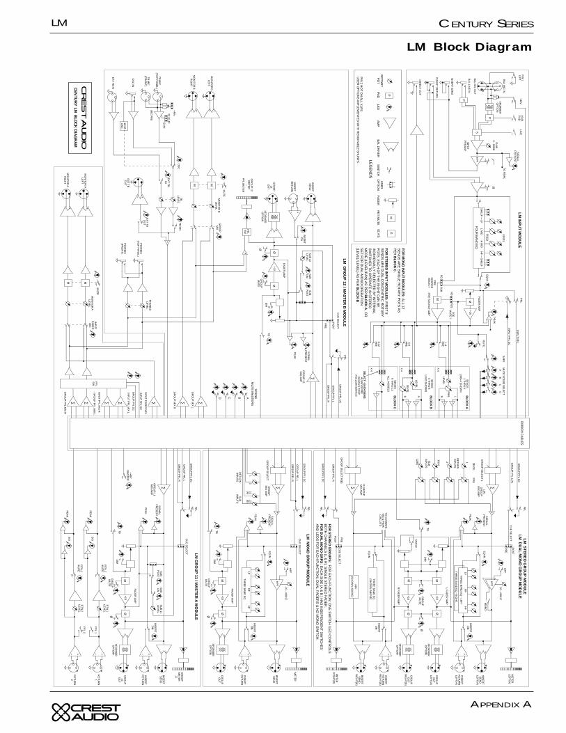
.
LM Block Diagram
LM CENTURY SERIES
APPENDIX A
LM
APPENDIX A
CENTURY SERIES
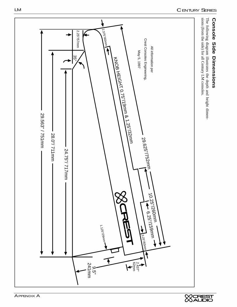
Console
Sid
e D
imensio
ns
The follow
ing diagram illustrates the depth and height dim
en-sions (from
the side) for all Century L
M consoles.
2.25"/57mm
KN
OB
HE
IGH
T 0.75"/19m
m &
1.25"/32mm
24.75"/ 717mm
28.0"/ 711mm
29.563" / 751mm
29.625"/752mm
10.25"/260mm
6.25"/159mm3.25"/83m
m
9.5"241m
m
2.437"62m
m
1.125"/29mm
2.375"/60mm
35°
All inform
ation per
Crest C
onsoles Engineering,
May 5, 1997
LM
APPENDIX A
CENTURY SERIES
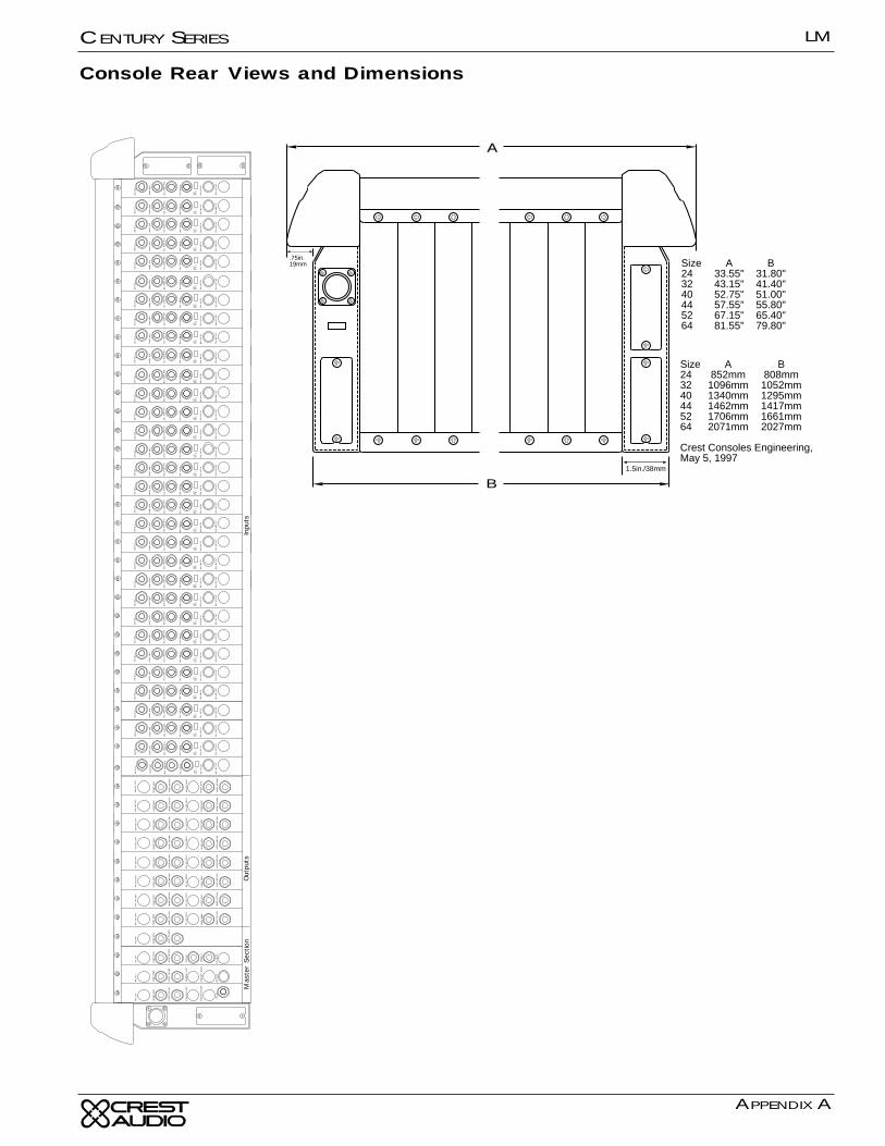
Console Rear Views and Dimensions
A
B
.75in.19mm
1.5in./38mm
Size A B24 33.55" 31.80"32 43.15" 41.40"40 52.75" 51.00"44 57.55" 55.80"52 67.15" 65.40"64 81.55" 79.80"
Size A B24 852mm 808mm32 1096mm 1052mm40 1340mm 1295mm44 1462mm 1417mm52 1706mm 1661mm64 2071mm 2027mm
Crest Consoles Engineering,May 5, 1997
INSER
T R
ETU
RN
MON
ITOR
A L
EFT
BAL
OU
T
INSER
T SEN
D
EXT
TB IN
INSER
T R
ETU
RN
MON
ITOR
B L
EFT
MON
ITOR
B R
IGH
T
BAL
OU
T
INSER
T SEN
D
OSC IN
MON
ITOR
A R
IGH
T
BAL
OU
T
INSER
T SEN
D
INSER
T R
ETU
RN
RET
UR
N 1
RET
UR
N 2
EXT
TB O
UT
BAL
OU
T
INSER
T SEN
D
INSER
T R
ETU
RN
INSER
T SEN
D
INSER
T SEN
D
INSER
T R
ETU
RN
BAL
OU
T LE
FT
INSER
T SEN
D
INSER
T R
ETU
RN
BAL
OU
T LE
FT
INSER
T SEN
D
INSER
T R
ETU
RN
BAL
OU
T LE
FT
INSER
T R
ETU
RN
BAL
OU
T R
IGH
TB
AL
OU
T R
IGH
T
INSER
T R
ETU
RN
BAL
OU
T R
IGH
T
INSER
T SEN
D
INSER
T R
ETU
RN
BAL
OU
T LE
FT
INSER
T SEN
D
INSER
T R
ETU
RN
BAL
OU
T R
IGH
T
INSER
T SEN
D
INSER
T R
ETU
RN
BAL
OU
T LE
FT
INSER
T SEN
D
INSER
T R
ETU
RN
BAL
OU
T R
IGH
T
INSER
T SEN
D
INSER
T R
ETU
RN
BAL
OU
T LE
FT
INSER
T SEN
D
INSER
T R
ETU
RN
BAL
OU
T R
IGH
T
INSER
T SEN
D
INSER
T R
ETU
RN
BAL
OU
T LE
FT
INSER
T SEN
D
INSER
T R
ETU
RN
BAL
OU
T R
IGH
T
INSER
T SEN
D
INSER
T R
ETU
RN
BAL
OU
T LE
FT
INSER
T SEN
D
INSER
T R
ETU
RN
BAL
OU
T R
IGH
T
INSER
T SEN
D
INSER
T R
ETU
RN
INSER
T SEN
D
DIR
OU
TD
IR O
UT
DIR
OU
TD
IR O
UT
DIR
OU
TD
IR O
UT
DIR
OU
TD
IR O
UT
DIR
OU
TD
IR O
UT
DIR
OU
TD
IR O
UT
DIR
OU
TD
IR O
UT
DIR
OU
TD
IR O
UT
DIR
OU
TD
IR O
UT
DIR
OU
TD
IR O
UT
DIR
OU
TD
IR O
UT
DIR
OU
TD
IR O
UT
DIR
OU
TD
IR O
UT
DIR
OU
TD
IR O
UT
DIR
OU
TD
IR O
UT
DIR
OU
TD
IR O
UT
BAL
INSR
T R
TN
INSR
T SN
D
BAL
MIC
IN
BAL
MIC
OU
T
LIFT
PIN
1
BAL
LIN
E IN
BAL
INSR
T R
TN
INSR
T SN
D
BAL
MIC
IN
BAL
MIC
OU
T
LIFT
PIN
1
BAL
LIN
E IN
BAL
INSR
T R
TN
INSR
T SN
D
BAL
MIC
IN
BAL
MIC
OU
T
LIFT
PIN
1
BAL
LIN
E IN
BAL
INSR
T R
TN
INSR
T SN
D
BAL
MIC
IN
BAL
MIC
OU
T
LIFT
PIN
1
BAL
LIN
E IN
BAL
INSR
T R
TN
INSR
T SN
D
BAL
MIC
IN
BAL
MIC
OU
T
LIFT
PIN
1
BAL
LIN
E IN
BAL
INSR
T R
TN
INSR
T SN
D
BAL
MIC
IN
BAL
MIC
OU
T
LIFT
PIN
1
BAL
LIN
E IN
BAL
INSR
T R
TN
INSR
T SN
D
BAL
MIC
IN
BAL
MIC
OU
T
LIFT
PIN
1
BAL
LIN
E IN
BAL
INSR
T R
TN
INSR
T SN
D
BAL
MIC
IN
BAL
MIC
OU
T
LIFT
PIN
1
BAL
LIN
E IN
BAL
INSR
T R
TN
INSR
T SN
D
BAL
MIC
IN
BAL
MIC
OU
T
LIFT
PIN
1
BAL
LIN
E IN
BAL
INSR
T R
TN
INSR
T SN
D
BAL
MIC
IN
BAL
MIC
OU
T
LIFT
PIN
1
BAL
LIN
E IN
BAL
INSR
T R
TN
INSR
T SN
D
BAL
MIC
IN
BAL
MIC
OU
T
LIFT
PIN
1
BAL
LIN
E IN
BAL
INSR
T R
TN
INSR
T SN
D
BAL
MIC
IN
BAL
MIC
OU
T
LIFT
PIN
1
BAL
LIN
E IN
BAL
INSR
T R
TN
INSR
T SN
D
BAL
MIC
IN
BAL
MIC
OU
T
LIFT
PIN
1
BAL
LIN
E IN
BAL
INSR
T R
TN
INSR
T SN
D
BAL
MIC
IN
BAL
MIC
OU
T
LIFT
PIN
1
BAL
LIN
E IN
BAL
INSR
T R
TN
INSR
T SN
D
BAL
MIC
IN
BAL
MIC
OU
T
LIFT
PIN
1
BAL
LIN
E IN
BAL
INSR
T R
TN
INSR
T SN
D
BAL
MIC
IN
BAL
MIC
OU
T
LIFT
PIN
1
BAL
LIN
E IN
BAL
INSR
T R
TN
INSR
T SN
D
BAL
MIC
IN
BAL
MIC
OU
T
LIFT
PIN
1
BAL
LIN
E IN
BAL
INSR
T R
TN
INSR
T SN
D
BAL
MIC
IN
BAL
MIC
OU
T
LIFT
PIN
1
BAL
LIN
E IN
BAL
INSR
T R
TN
INSR
T SN
D
BAL
MIC
IN
BAL
MIC
OU
T
LIFT
PIN
1
BAL
LIN
E IN
BAL
INSR
T R
TN
INSR
T SN
D
BAL
MIC
IN
BAL
MIC
OU
T
LIFT
PIN
1
BAL
LIN
E IN
BAL
INSR
T R
TN
INSR
T SN
D
BAL
MIC
IN
BAL
MIC
OU
T
LIFT
PIN
1
BAL
LIN
E IN
BAL
INSR
T R
TN
INSR
T SN
D
BAL
MIC
IN
BAL
MIC
OU
T
LIFT
PIN
1
BAL
LIN
E IN
BAL
INSR
T R
TN
INSR
T SN
D
BAL
MIC
IN
BAL
MIC
OU
T
LIFT
PIN
1
BAL
LIN
E IN
BAL
INSR
T R
TN
INSR
T SN
D
BAL
MIC
IN
BAL
MIC
OU
T
LIFT
PIN
1
BAL
LIN
E IN
BAL
INSR
T R
TN
INSR
T SN
D
BAL
MIC
IN
BAL
MIC
OU
T
LIFT
PIN
1
BAL
LIN
E IN
BAL
INSR
T R
TN
INSR
T SN
D
BAL
MIC
IN
BAL
MIC
OU
T
LIFT
PIN
1
BAL
LIN
E IN
BAL
INSR
T R
TN
INSR
T SN
D
BAL
MIC
IN
BAL
MIC
OU
T
LIFT
PIN
1
BAL
LIN
E IN
BAL
INSR
T R
TN
INSR
T SN
D
BAL
MIC
IN
BAL
MIC
OU
T
LIFT
PIN
1
BAL
LIN
E IN
BAL
INSR
T R
TN
INSR
T SN
D
BAL
MIC
IN
BAL
MIC
OU
T
LIFT
PIN
1
BAL
LIN
E IN
BAL
INSR
T R
TN
INSR
T SN
D
BAL
MIC
IN
BAL
MIC
OU
T
LIFT
PIN
1
BAL
LIN
E IN
BAL
INSR
T R
TN
INSR
T SN
D
BAL
MIC
IN
BAL
MIC
OU
T
LIFT
PIN
1
BAL
LIN
E IN
BAL
INSR
T R
TN
INSR
T SN
D
BAL
MIC
IN
BAL
MIC
OU
T
LIFT
PIN
1
BAL
LIN
E IN
Mas
ter
Sec
tion
Out
puts
Inpu
ts
LM
APPENDIX A
CENTURY SERIES
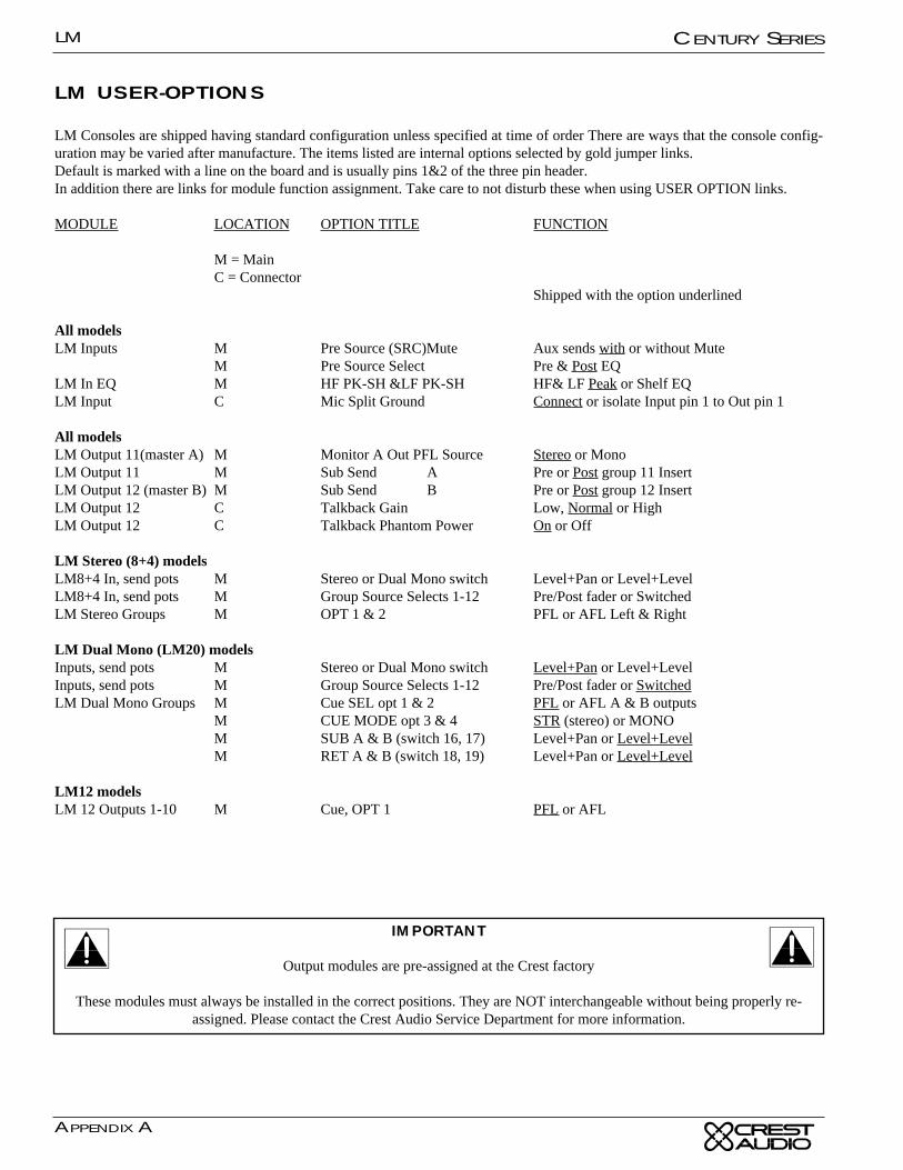
LM USER-OPTIONS
LM Consoles are shipped having standard configuration unless specified at time of order There are ways that the console config-uration may be varied after manufacture. The items listed are internal options selected by gold jumper links.Default is marked with a line on the board and is usually pins 1&2 of the three pin header.In addition there are links for module function assignment. Take care to not disturb these when using USER OPTION links.
MODULE LOCATION OPTION TITLE FUNCTION
M = MainC = Connector
Shipped with the option underlined
All modelsLM Inputs M Pre Source (SRC)Mute Aux sends with or without Mute
M Pre Source Select Pre & Post EQLM In EQ M HF PK-SH &LF PK-SH HF& LF Peak or Shelf EQLM Input C Mic Split Ground Connect or isolate Input pin 1 to Out pin 1
All modelsLM Output 11(master A) M Monitor A Out PFL Source Stereo or MonoLM Output 11 M Sub Send A Pre or Post group 11 InsertLM Output 12 (master B) M Sub Send B Pre or Post group 12 InsertLM Output 12 C Talkback Gain Low, Normal or HighLM Output 12 C Talkback Phantom Power On or Off
LM Stereo (8+4) modelsLM8+4 In, send pots M Stereo or Dual Mono switch Level+Pan or Level+LevelLM8+4 In, send pots M Group Source Selects 1-12 Pre/Post fader or SwitchedLM Stereo Groups M OPT 1 & 2 PFL or AFL Left & Right
LM Dual Mono (LM20) modelsInputs, send pots M Stereo or Dual Mono switch Level+Pan or Level+LevelInputs, send pots M Group Source Selects 1-12 Pre/Post fader or SwitchedLM Dual Mono Groups M Cue SEL opt 1 & 2 PFL or AFL A & B outputs
M CUE MODE opt 3 & 4 STR (stereo) or MONOM SUB A & B (switch 16, 17) Level+Pan or Level+LevelM RET A & B (switch 18, 19) Level+Pan or Level+Level
LM12 modelsLM 12 Outputs 1-10 M Cue, OPT 1 PFL or AFL
IMPORTANT
Output modules are pre-assigned at the Crest factory
These modules must always be installed in the correct positions. They are NOT interchangeable without being properly re-assigned. Please contact the Crest Audio Service Department for more information.
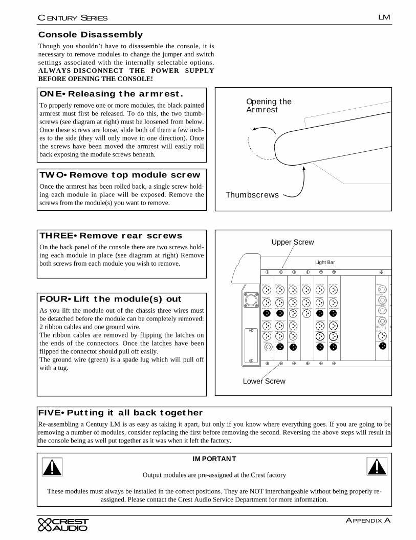
LM
APPENDIX A
CENTURY SERIES
Console DisassemblyThough you shouldn’t have to disassemble the console, it isnecessary to remove modules to change the jumper and switchsettings associated with the internally selectable options.ALWAYS DISCONNECT THE POWER SUPPLYBEFORE OPENING THE CONSOLE!
ONE•Releasing the armrest.To properly remove one or more modules, the black paintedarmrest must first be released. To do this, the two thumb-screws (see diagram at right) must be loosened from below.Once these screws are loose, slide both of them a few inch-es to the side (they will only move in one direction). Oncethe screws have been moved the armrest will easily rollback exposing the module screws beneath.
TWO•Remove top module screwOnce the armrest has been rolled back, a single screw hold-ing each module in place will be exposed. Remove thescrews from the module(s) you want to remove.
THREE•Remove rear screwsOn the back panel of the console there are two screws hold-ing each module in place (see diagram at right) Removeboth screws from each module you wish to remove.
FOUR•Lift the module(s) outAs you lift the module out of the chassis three wires mustbe detatched before the module can be completely removed:2 ribbon cables and one ground wire.The ribbon cables are removed by flipping the latches onthe ends of the connectors. Once the latches have beenflipped the connector should pull off easily.The ground wire (green) is a spade lug which will pull offwith a tug.
FIVE•Putting it all back togetherRe-assembling a Century LM is as easy as taking it apart, but only if you know where everything goes. If you are going to beremoving a number of modules, consider replacing the first before removing the second. Reversing the above steps will result inthe console being as well put together as it was when it left the factory.
Opening theArmrest
Thumbscrews
INSERT RETURN
MONITOR A LEFT
BAL OUT
INSERT SEND
EXT TB IN
INSERT RETURN
MONITOR B LEFT
MONITOR B RIGHT
BAL OUT
INSERT SEND
OSC IN
MONITOR A RIGHT
BAL OUT
INSERT SEND
INSERT RETURN
RETURN 1
RETURN 2
EXT TB OUT
BAL OUT
INSERT SEND
INSERT RETURN
BAL INSRT RTN
DIR OUT
INSRT SND
BAL MIC IN
BAL MIC OUT
LIFTPIN 1
BAL LINE IN
BAL
DIR
INSR
BAL
BAL
LIFTPIN
BAL
Upper Screw
INSERT RETURN
BAL OUT LEFT
INSERT SEND
INSERT RETURN
BAL OUT RIGHT
INSERT SEND
INSERT RETURN
BAL OUT LEFT
INSERT SEND
INSERT RETURN
BAL OUT RIGHT
INSERT SEND
Lower Screw
Light Bar
IMPORTANT
Output modules are pre-assigned at the Crest factory
These modules must always be installed in the correct positions. They are NOT interchangeable without being properly re-assigned. Please contact the Crest Audio Service Department for more information.


Appendix B
Glossary
LM
LM
APPENDIX B
CENTURY SERIES
GlossaryBalanced Insert Return See Insert Return
Balanced Line InSee Line Input
Balanced Mic InSee Microphone Input
Balanced Mic Out See Microphone Output
Balanced Out See Outputs
DIM SwitchIntroduces a -6dB drop to the output signal. This is a pushon/push off switch allows the operator to temporarily drop thelevel of a monitor without actually changing any settings.
Direct OutThis jack carries the direct output signal (post fader & postmute) from each input channel. This signal can be used forconnection to recording devices or routing of the post fadersignal.
EQ IN SwitchInserts the EQ section into the input/output channel signal. Anassociated LED illuminates when the switch is down.
Equalizer Controls (Input)There are two knobs for each of the four bands. The inner knobcontrols the boost or cut; while the outer knob controls the cen-ter frequency adjusted by the inner knob. These center frequen-cies are printed on the chassis around the outer knob. This EQis active only when the EQ In switch is depressed.
Equalizer Controls (Output)Controls the equalization of the output mix signal throughthree bands, via six controls. The upper knob of each banddetermines the center frequency (high-1kHz-20kHz, mid-300Hz-8kHz, low-40Hz, 1kHz), while the lower knob adjuststhe amount of boost or cut.
External Talkback InputIn addition to the mic connections on the console surface, anadditional Talkback input connection is provided on the rear ofthe master section. Signal connected to this jack appears on theTalkback bus whenever the External TB Input switch isdepressed.
External Talkback Output
This allows the internal TB signals present on the Talkbackbus to be routed to an external destination such as a link to theFOH console. Signal appears on this jack when both theExternal TB Output switch and talkback master switches aredepressed.
FaderUsed for final output control of an input/output channel exceptthose sends selected pre fader. (Insert Output levels are notaffected by the fader position.)
Gain ControlAdjusts input gain for proper signal level on the input. To setthe gain to the best position, make sure there is signal presentat the input. Depress the PFL switch on that input channel andmake sure that no other PFL switches are depressed. Adjust thegain control until the PFL meter (on output module 12) ispeaking around the +3 level.
Group Mix SwitchThis switch activates circuitry that sums all output mixes andassigns the summed signal to the Monitor B output. This out-put is stereo when stereo signals are present. This signal is postfader.
Headphone JackAllows for connection of headphones via a 1/4" TRS plug.There are two headphone jacks: one on master module B, andone underneath the armrest on the right front corner of the con-sole.
Headphone Level ControlControls the output level of both headphone jacks.
High Pass Filter SwitchThis switch inserts the High Pass Filter into the output signal.Unlike the 100Hz HPF on the inputs, the output HPF isadjustable via the HPF frequency control.
HPF Frequency ControlThis knob adjusts the high pass filter frequency from 20Hz to400Hz. The filter operates at a -12 dB per octave rate.
100 Hz High Pass Filter (Input)Reduces all Input signal low frequency content at a 12db peroctave rate referenced to 100Hz (-3db point).
InsertAll LM inputs and outputs have insert loops which facilitatethe patching of external processing equipment into the input oroutput signal. All LM inserts are pre EQ.
On the inputs, signal is always present at the Insert Send con-nection and the loop is complete when the proper connector isplugged into the Insert Return. The Insert Return can also beused as a line input when by-passing the preamp is desired.
On the outputs, the loop is controlled by the Insert On switch.Depressing this switch inserts the loop into the output signal.Since this a true insert, if an incomplete loop exists, depressingthe switch will mute the output.
Input/Output PFL IndicatorsThese LEDs indicate what type of signal (input or output) isPFL’d at any given time.
LM
APPENDIX B
CENTURY SERIES
Input Fader Mix SwitchThis switch activates circuitry that sums all input signals andassigns the summed signal to the Monitor A output. This signalis post fader.
Lamp Dim ControlControls the brightness of any 12 volt lighting devices attachedto the XLR connectors on the light bar.
LINE SwitchSelects the input signal source between the Balanced XLRMicrophone Input connector and the Balanced Line Input 1/4"TRS connector.
Line InputThis jack accepts balanced and unbalanced line level inputsand delivers it into the associated input channel.
Microphone InputThis connector accepts balanced microphone inputs for theassociated input channel.
Microphone OutputThis connector is in parallel with the Balanced Mic In connec-tor and allows easy connection of the monitor board to theFOH console.
Mix SendsEvery LM console has twelve (12) send controls. Each LMmodel deals with these twelve controls differently:
LM-12 • Each of the twelve knobs determine the amount ofsignal sent to each of the twelve outputs.
LM-8+4 • The first eight controls are dual concentric and theydetermine the amount of signal sent to the first eight stereooutputs. The center knob controls level while the outer knob isa PAN control. The last four knobs adjust the level of signalsent to outputs 9-12.
LM-20 • The first eight controls are dual concentric and theydetermine the amount of signal sent to the first sixteen outputs(1a/1b . . 8a/8b). The last four knobs adjust the level of signalsent to outputs 9-12.
Monitor A/B These are stereo local monitor outputs. Level is controlled viathe Monitor Level control and the signal is found on balancedoutput connectors (two per monitor) on the rear of the mastersection. Each Monitor can be muted with the Monitor Muteswitch. See - Input Fader Mix and Group Mix for more infor-mation.
MUTE Switch with LEDOn all inputs and outputs where this switch is present, depress-ing it will mute all sends. This switch does not affect the PFLswitch or the Peak and Signal Present LED indicators, TheLED illuminates when the channel is muted either from theswitch or via the scene mute system.
Oscillator OnSwitches on the internal (or external if connected) oscillatorwhich is fixed at 1kHz . The oscillator only operates when theTalkback system is engaged.
Oscillator / Pink Noise InThis connector accepts a balanced or unbalanced signal froman oscillator or pink noise generator. This signal is assignablevia the Talkback assignment switches. The external source isswitched in via the Oscillator On switch. The internal 1kHzoscillator is defeated when a plug inserted.
Output Insert - See InsertOutput EQ - See Equalizer Controls (Output)
PAD SwitchIntroduces a -15 dB drop to the mic input signal.
PEAK LED IndicatorIlluminates RED when any of the points monitored come with-in 3db of the clipping point. Signal is sampled after the inputpreamplifier stage, after the EQ section, and after the fader.
This LED also serves as a PFL ON indicator, but at a muchlower intensity than when it is used to indicate clipping.
PFL IndicatorThis LED illuminates when the signal on meter 12 is a PFL orAFL signal
Phantom Power SwitchTurns on 48V Phantom Power as required by certain micro-phones for proper operation. This switch delivers +48V onlywhen the Phantom Power Master Switch is engaged.
Phantom Master Switch w/LEDSwitches +48V phantom power on and off for the entire con-sole.
Power IndicatorsShows the status of the four voltages used by the console.
Polarity Reverse SwitchElectrically inverts the polarity of associated signal.
PRE Switch Toggles mix sends (in groups of four) between Post and theinternally selected Pre state. See the Internal Settings section ofthe Technical Appendix.
PFL SwitchSamples the channel’s signal pre-fader and allows for monitor-ing within the master section of the console. This signal is notaffected by the Mute Switch. When depressed, the signal levelcan be seen on the output 12 meter, and heard via the mixer’sheadphone or local monitor output. When this PFL Switch isdepressed, the channel PEAK LED indicator illuminates at alower intensity. When used as a status indicator of switch posi-tion, the Peak LED indicating circuit remains fully operationby illuminating at a much higher intensity than its use as a PFLstatus indicator. Input PFL always takes priority over outputPFL.
LM
APPENDIX B
CENTURY SERIES
Return 1/2These connectors accept a balanced signal which is deliveredto the return master controls on the master section
Return Level ControlsAdjusts the level of return signals 1 and 2 in the output. Thesesignals come from the Master Section. The center knob adjustslevel while the outer knob adjusts panning within the stereoimage. See Returns 1 & 2 on the Master Section description formore information.
Return Master Level ControlsControls the final return signal level available to the outputs.
Scene Mute AssignmentsAssign the input channel to any of the four scene mute groups.Scene mute combines with the module’s local mute button, andactuates the local mute LED.
Scene Mute MastersThese four switches turn the four scene mutes on and off forthe entire console.
Scene Mute Safe SwitchDisables any selected scene mute assignments. An associatedgreen LED indicates the channel is in a safe state.
Signal Present LEDThis green LED constantly displays level activity of theinput/output channel by varying in intensity.
Sub Input ControlsAdjusts the level of cross-mix in the output from mono outputs11 and 12. The center knob adjusts level while the outer knobadjusts panning within the stereo image.
Sub 11/12 Post SwitchSwitches the subgroup between pre and post fader.
Sub 11/12 On SwitchSwitches the subgroup send on and off.
Talkback Master On/OffSwitches the internal Talkback system on and off
TB Enable SwitchInjects the talkback signal from the master section into the theassociated output.
Talkback Level ControlAdjusts the final level of all Talkback signals.
Talkback Mic InputAllows for connection of a gooseneck or other XLR typemicrophone to the Talkback system.
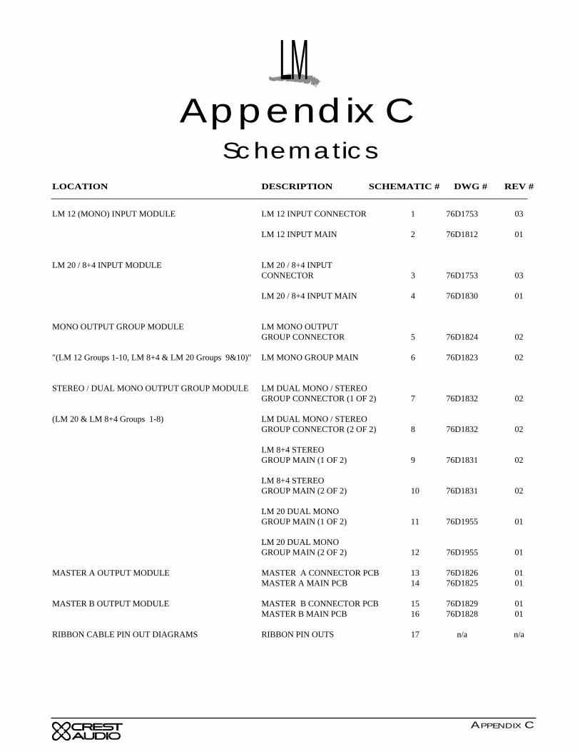
LOCATION DESCRIPTION SCHEMATIC # DWG # REV #
LM 12 (MONO) INPUT MODULE LM 12 INPUT CONNECTOR 1 76D1753 03
LM 12 INPUT MAIN 2 76D1812 01
LM 20 / 8+4 INPUT MODULE LM 20 / 8+4 INPUTCONNECTOR 3 76D1753 03
LM 20 / 8+4 INPUT MAIN 4 76D1830 01
MONO OUTPUT GROUP MODULE LM MONO OUTPUTGROUP CONNECTOR 5 76D1824 02
"(LM 12 Groups 1-10, LM 8+4 & LM 20 Groups 9&10)" LM MONO GROUP MAIN 6 76D1823 02
STEREO / DUAL MONO OUTPUT GROUP MODULE LM DUAL MONO / STEREOGROUP CONNECTOR (1 OF 2) 7 76D1832 02
(LM 20 & LM 8+4 Groups 1-8) LM DUAL MONO / STEREOGROUP CONNECTOR (2 OF 2) 8 76D1832 02
LM 8+4 STEREOGROUP MAIN (1 OF 2) 9 76D1831 02
LM 8+4 STEREOGROUP MAIN (2 OF 2) 10 76D1831 02
LM 20 DUAL MONOGROUP MAIN (1 OF 2) 11 76D1955 01
LM 20 DUAL MONOGROUP MAIN (2 OF 2) 12 76D1955 01
MASTER A OUTPUT MODULE MASTER A CONNECTOR PCB 13 76D1826 01MASTER A MAIN PCB 14 76D1825 01
MASTER B OUTPUT MODULE MASTER B CONNECTOR PCB 15 76D1829 01MASTER B MAIN PCB 16 76D1828 01
RIBBON CABLE PIN OUT DIAGRAMS RIBBON PIN OUTS 17 n/a n/a
LMAppendix C
Schematics
APPENDIX C
LM Owners ManualCopyright © 1997 Crest Audio Inc.
v. 2.3 11/3/97 - D7000002
Crest Audio Inc.100 Eisenhower Dr., Paramus NJ 07652 USA
TEL: 201.909.8700 FAX: 201.909.8744http://www.crestaudio.com
Printed in USA
*D7000002*