Embed Size (px)
Citation preview

7/24/2019 Cerabar S PMC71, PMP71, PMP75
http://slidepdf.com/reader/full/cerabar-s-pmc71-pmp71-pmp75 1/116
Pressure transmitter with ceramic andmetal sensors
Applications
The device is used for the following measuring tasks:• Absolute pressure and gauge pressure measurement in gases, steams or liquids in
all areas of process engineering and process measurement technology • Level, volume or mass measurements in liquids• High process temperatures
– without diaphragm seals up to 150 °C (302 °F)
– with typical diaphragm seals up to 400 °C (752 °F)• High pressures up to 700 bar (10 500 psi)• MID part certificate according to OIML R117-1 Edition 2007 (E) and EN
12405-1/A1 Edition 2006
The benefits for you
• Very good reproducibility and long-term stability • High reference accuracy up to ±0.025 %• Turn down up to 100:1, higher on request• Used for process pressure monitoring up to SIL 3, certified to IEC 61508 by TÜV
SÜD• High level of safety during operation thanks to function monitoring from the
measuring cell to the electronics
• The patented TempC diaphragm for the diaphragm seal reduces measured errorscaused by environmental and process temperature influences to a minimum• Easy electronic replacement guaranteed with HistoROM®/M-DAT• Uniform platform for differential pressure, hydrostatics and pressure (Deltabar S –
Deltapilot S – Cerabar S)• Practical user navigation for quick and easy commissioning• Extensive diagnostic functions
Products Solutions Services
Technical Information
Cerabar S PMC71, PMP71,PMP75Process pressure measurement
TI00383P/00/EN/23.1571296975

7/24/2019 Cerabar S PMC71, PMP71, PMP75
http://slidepdf.com/reader/full/cerabar-s-pmc71-pmp71-pmp75 2/116
Cerabar S PMC71, PMP71, PMP75
2 Endress+Hauser
Table of contents
Document information . . . . . . . . . . . . . . . . . . . . . . . 4
Document function . . . . . . . . . . . . . . . . . . . . . . . . . . . . 4Symbols used . . . . . . . . . . . . . . . . . . . . . . . . . . . . . . . . 4Documentation . . . . . . . . . . . . . . . . . . . . . . . . . . . . . . . 5Terms and abbreviations . . . . . . . . . . . . . . . . . . . . . . . . 5
Function and system design . . . . . . . . . . . . . . . . . . . 7Device features . . . . . . . . . . . . . . . . . . . . . . . . . . . . . . . 7Measuring principle . . . . . . . . . . . . . . . . . . . . . . . . . . . . 8Product design . . . . . . . . . . . . . . . . . . . . . . . . . . . . . . . 9
Applications suitable for custody transfer measurement . . . . 9Communication protocol . . . . . . . . . . . . . . . . . . . . . . . . 10
Input . . . . . . . . . . . . . . . . . . . . . . . . . . . . . . . . . . . . 11
Measured variable . . . . . . . . . . . . . . . . . . . . . . . . . . . . 11Measuring range . . . . . . . . . . . . . . . . . . . . . . . . . . . . . 11
Output . . . . . . . . . . . . . . . . . . . . . . . . . . . . . . . . . . 14Output signal . . . . . . . . . . . . . . . . . . . . . . . . . . . . . . . 14Signal range 4 to 20 mA . . . . . . . . . . . . . . . . . . . . . . . . 14Signal on alarm . . . . . . . . . . . . . . . . . . . . . . . . . . . . . . 14Maximum load - 4 to 20 mA HART . . . . . . . . . . . . . . . . . 15Dead time, time constant . . . . . . . . . . . . . . . . . . . . . . . 15Dynamic behavior: current output . . . . . . . . . . . . . . . . . . 16Dynamic behavior: Digital output (HART electronics) . . . . . 16Dynamic behavior: PROFIBUS PA . . . . . . . . . . . . . . . . . . 16Dynamic behavior: FOUNDATION Fieldbus . . . . . . . . . . . . 17
Damping . . . . . . . . . . . . . . . . . . . . . . . . . . . . . . . . . . 17 Alarm current. . . . . . . . . . . . . . . . . . . . . . . . . . . . . . . 18
Firmw are version . . . . . . . . . . . . . . . . . . . . . . . . . . . . 18Protocol-specific data . . . . . . . . . . . . . . . . . . . . . . . . . . 18
Power supply . . . . . . . . . . . . . . . . . . . . . . . . . . . . . 22Terminal assignment . . . . . . . . . . . . . . . . . . . . . . . . . . 22Suppl y voltage . . . . . . . . . . . . . . . . . . . . . . . . . . . . . . 23Current consumption . . . . . . . . . . . . . . . . . . . . . . . . . . 23Electrical connection . . . . . . . . . . . . . . . . . . . . . . . . . . 24Terminals . . . . . . . . . . . . . . . . . . . . . . . . . . . . . . . . . 24Cable entries. . . . . . . . . . . . . . . . . . . . . . . . . . . . . . . 24Connector . . . . . . . . . . . . . . . . . . . . . . . . . . . . . . . . . 24
Cable specification. . . . . . . . . . . . . . . . . . . . . . . . . . . . 25Start-up current . . . . . . . . . . . . . . . . . . . . . . . . . . . . . 26Residual ripple . . . . . . . . . . . . . . . . . . . . . . . . . . . . . . 26Overv oltage protection (optional) . . . . . . . . . . . . . . . . . . 26Influence of power supply . . . . . . . . . . . . . . . . . . . . . . . 26
Performance characteristics of ceramic processisolating diaphragm . . . . . . . . . . . . . . . . . . . . . . . . 27Reference operating conditions . . . . . . . . . . . . . . . . . . . 27Measuring uncertainty for small absolute pressuremeasuring ranges . . . . . . . . . . . . . . . . . . . . . . . . . . . . 27Influence of the installation position . . . . . . . . . . . . . . . . 27Resolution . . . . . . . . . . . . . . . . . . . . . . . . . . . . . . . . . 27
Reference accuracy . . . . . . . . . . . . . . . . . . . . . . . . . . . 27Thermal change of the zero output and the output span . . . 28Total performance . . . . . . . . . . . . . . . . . . . . . . . . . . . . 28Long-term stability . . . . . . . . . . . . . . . . . . . . . . . . . . . 28
Total error . . . . . . . . . . . . . . . . . . . . . . . . . . . . . . . . . 29 Warm-up period . . . . . . . . . . . . . . . . . . . . . . . . . . . . . 29
Performance characteristics of the metallicprocess isolating diaphragm . . . . . . . . . . . . . . . . . . 30Reference operating conditions . . . . . . . . . . . . . . . . . . . 30Measuring uncertainty for small absolute pressuremeasuring ranges . . . . . . . . . . . . . . . . . . . . . . . . . . . . 30Influence of the installation position . . . . . . . . . . . . . . . . 30Resolution . . . . . . . . . . . . . . . . . . . . . . . . . . . . . . . . . 30Reference accuracy . . . . . . . . . . . . . . . . . . . . . . . . . . . 30Thermal change of the zero output and the output span . . . 32Total performance . . . . . . . . . . . . . . . . . . . . . . . . . . . . 33Long-term stability . . . . . . . . . . . . . . . . . . . . . . . . . . . 33Total error . . . . . . . . . . . . . . . . . . . . . . . . . . . . . . . . . 33
Warm-up period . . . . . . . . . . . . . . . . . . . . . . . . . . . . . 33
Installation . . . . . . . . . . . . . . . . . . . . . . . . . . . . . . . 34General installation instructions . . . . . . . . . . . . . . . . . . . 34Measuring arrangement for devices without diaphragmseals – PMC71, PMP71 . . . . . . . . . . . . . . . . . . . . . . . . 34Measuring arrangement for devices with diaphragm seals– PMP75 . . . . . . . . . . . . . . . . . . . . . . . . . . . . . . . . . . 34Orientation . . . . . . . . . . . . . . . . . . . . . . . . . . . . . . . . 34
Wall and pipe mounting . . . . . . . . . . . . . . . . . . . . . . . . 34Heat insulation – PMC71 high-temperature version . . . . . 35Mounting of PVDF screw-in fittings . . . . . . . . . . . . . . . . 35
"Separate housing" version . . . . . . . . . . . . . . . . . . . . . . . 36Turning the housing . . . . . . . . . . . . . . . . . . . . . . . . . . 38Oxygen applications . . . . . . . . . . . . . . . . . . . . . . . . . . . 39Silicone-free applications . . . . . . . . . . . . . . . . . . . . . . . 39Ultrapure gas applications . . . . . . . . . . . . . . . . . . . . . . . 39
Applications with hydrogen . . . . . . . . . . . . . . . . . . . . . . 39
Environment . . . . . . . . . . . . . . . . . . . . . . . . . . . . . . 40 Ambient temperature range . . . . . . . . . . . . . . . . . . . . . 40
Storage temperature range . . . . . . . . . . . . . . . . . . . . . . 40Degree of protection . . . . . . . . . . . . . . . . . . . . . . . . . . 40Climate class . . . . . . . . . . . . . . . . . . . . . . . . . . . . . . . 40Electromagnetic compatibility . . . . . . . . . . . . . . . . . . . . 40
Vibration resistance . . . . . . . . . . . . . . . . . . . . . . . . . . . 41
Process . . . . . . . . . . . . . . . . . . . . . . . . . . . . . . . . . . 42Process temperature limits . . . . . . . . . . . . . . . . . . . . . . 42Pressure specifications . . . . . . . . . . . . . . . . . . . . . . . . . 44
Mechanical construction . . . . . . . . . . . . . . . . . . . . 45Device height . . . . . . . . . . . . . . . . . . . . . . . . . . . . . . . 45T14 housing, optional display on the side . . . . . . . . . . . . 46T17 housing (hygienic), optional display on the side . . . . . 47Process connections for PMC71 with internal processisolating diaphragm . . . . . . . . . . . . . . . . . . . . . . . . . . . 48Process connections for PMC71 with internal process
isolating diaphragm . . . . . . . . . . . . . . . . . . . . . . . . . . . 50Process connections for PMC71 with internal processisolating diaphragm - height H . . . . . . . . . . . . . . . . . . . 50

7/24/2019 Cerabar S PMC71, PMP71, PMP75
http://slidepdf.com/reader/full/cerabar-s-pmc71-pmp71-pmp75 3/116
Cerabar S PMC71, PMP71, PMP75
Endress+Hauser 3
Process connections for PMC71 with flush-mountedprocess isolating diaphragm . . . . . . . . . . . . . . . . . . . . . 51Process connections for PMC71 with flush-mountedprocess isolating diaphragm . . . . . . . . . . . . . . . . . . . . . 52Process connections for PMC71 with flush-mountedprocess isolating diaphragm - height H . . . . . . . . . . . . . . 52
Process connections for PMC71 with flush-mountedprocess isolating diaphragm . . . . . . . . . . . . . . . . . . . . . 53Hygienic process connections for PMC71 with flush-mounted process isolating diaphragm . . . . . . . . . . . . . . . 56Process connections for PMP71 with internal processisolating diaphragm . . . . . . . . . . . . . . . . . . . . . . . . . . . 58Process connections for PMP71 with internal processisolating diaphragm . . . . . . . . . . . . . . . . . . . . . . . . . . . 59Process connections for PMP71 with internal processisolating diaphragm . . . . . . . . . . . . . . . . . . . . . . . . . . . 60Process connections for PMP71 with flush-mountedprocess isolating diaphragm . . . . . . . . . . . . . . . . . . . . . 61Process connections for PMP71 with flush-mountedprocess isolating diaphragm . . . . . . . . . . . . . . . . . . . . . 63Process connections for PMP71 with flush-mountedprocess isolating diaphragm . . . . . . . . . . . . . . . . . . . . . 64Process connections for PMP71 with flush-mountedprocess isolating diaphragm . . . . . . . . . . . . . . . . . . . . . 65Process connections for PMP71 with flush-mountedprocess isolating diaphragm . . . . . . . . . . . . . . . . . . . . . 66Process connections for PMP71 . . . . . . . . . . . . . . . . . . . 67Process connections for PMP71 . . . . . . . . . . . . . . . . . . . 68PMP75 basic device . . . . . . . . . . . . . . . . . . . . . . . . . . . 69Process connections for PMP75 with flush-mountedprocess isolating diaphragm . . . . . . . . . . . . . . . . . . . . . 70Process connections for PMP75 with flush-mountedprocess isolating diaphragm . . . . . . . . . . . . . . . . . . . . . 71
Process connections for PMP75 with flush-mountedprocess isolating diaphragm . . . . . . . . . . . . . . . . . . . . . 72Process connections for PMP75 with flush-mountedprocess isolating diaphragm . . . . . . . . . . . . . . . . . . . . . 73Hygienic process connections for PMP75 with flush-mounted process isolating diaphragm . . . . . . . . . . . . . . . 74Hygienic process connections for PMP75 with flush-mounted process isolating diaphragm . . . . . . . . . . . . . . . 75Hygienic process connections for PMP75 with flush-mounted process isolating diaphragm . . . . . . . . . . . . . . . 77Process connections for PMP75 with flush-mountedprocess isolating diaphragm . . . . . . . . . . . . . . . . . . . . . 79Process connections for PMP75 with flush-mountedprocess isolating diaphragm . . . . . . . . . . . . . . . . . . . . . 81Process connections for PMP75 with flush-mountedprocess isolating diaphragm . . . . . . . . . . . . . . . . . . . . . 85Separate housing: Wall and pipe mounting with mountingbracket . . . . . . . . . . . . . . . . . . . . . . . . . . . . . . . . . . . 87Materials not in contact with process . . . . . . . . . . . . . . . 88Materials in contact with process . . . . . . . . . . . . . . . . . . 90Fill fluid . . . . . . . . . . . . . . . . . . . . . . . . . . . . . . . . . . . 92
Operability . . . . . . . . . . . . . . . . . . . . . . . . . . . . . . . 93Operating concept . . . . . . . . . . . . . . . . . . . . . . . . . . . . 93Local operation . . . . . . . . . . . . . . . . . . . . . . . . . . . . . . 93Remote operation . . . . . . . . . . . . . . . . . . . . . . . . . . . . 96HistoROM®/M-DAT (optional) . . . . . . . . . . . . . . . . . . . 97
System integration . . . . . . . . . . . . . . . . . . . . . . . . . . . 98
Planning instructions, diaphragm seal systems . . . 99 Applications . . . . . . . . . . . . . . . . . . . . . . . . . . . . . . . . 99
Design and operation mode . . . . . . . . . . . . . . . . . . . . . 100Diaphragm seal filling oils . . . . . . . . . . . . . . . . . . . . . . 101Information on cleaning . . . . . . . . . . . . . . . . . . . . . . . 102Installation instructions . . . . . . . . . . . . . . . . . . . . . . . 102
Vacuum applications . . . . . . . . . . . . . . . . . . . . . . . . . 104
Certificates and approvals . . . . . . . . . . . . . . . . . . 105CE mark . . . . . . . . . . . . . . . . . . . . . . . . . . . . . . . . . . 105C-tick mark . . . . . . . . . . . . . . . . . . . . . . . . . . . . . . . 105Ex approvals . . . . . . . . . . . . . . . . . . . . . . . . . . . . . . . 105Suitable for hy giene applications . . . . . . . . . . . . . . . . . 105Functional safety SIL/ IEC 61508 Declaration ofConformity (optional) . . . . . . . . . . . . . . . . . . . . . . . . . 105Overfill protection . . . . . . . . . . . . . . . . . . . . . . . . . . . 105CRN approval . . . . . . . . . . . . . . . . . . . . . . . . . . . . . . 106Other standards and guidelines . . . . . . . . . . . . . . . . . . 106Pressure Equipment Directive (PED) . . . . . . . . . . . . . . . 106Marine approv al . . . . . . . . . . . . . . . . . . . . . . . . . . . . 106Drinking water approval. . . . . . . . . . . . . . . . . . . . . . . 106
Approvals for custody transfer . . . . . . . . . . . . . . . . . . . 107MID Parts Certificate . . . . . . . . . . . . . . . . . . . . . . . . . 107Classification of process sealing between electricalsystems and (flammable or combustible) process fluids inaccordance with ANSI/ISA 12.27.01 . . . . . . . . . . . . . . . 107Inspection certificate . . . . . . . . . . . . . . . . . . . . . . . . . 107Calibration . . . . . . . . . . . . . . . . . . . . . . . . . . . . . . . . 108Certificate of Compliance ASME BPE . . . . . . . . . . . . . . . 108
Ordering inf ormation . . . . . . . . . . . . . . . . . . . . . . 109Scope of delivery . . . . . . . . . . . . . . . . . . . . . . . . . . . . 109Configuration data sheet . . . . . . . . . . . . . . . . . . . . . . . 109
Accessories . . . . . . . . . . . . . . . . . . . . . . . . . . . . . . 111HistoROM®/M-DAT . . . . . . . . . . . . . . . . . . . . . . . . . . 111
Wall and pipe mounting . . . . . . . . . . . . . . . . . . . . . . . 111 Welding flanges and welding neck . . . . . . . . . . . . . . . . 111
Supplementary documentation . . . . . . . . . . . . . . 112Field of Activities . . . . . . . . . . . . . . . . . . . . . . . . . . . . 112Technical Information . . . . . . . . . . . . . . . . . . . . . . . . 112Operating Instructions . . . . . . . . . . . . . . . . . . . . . . . . 112Brief Operating Instructions . . . . . . . . . . . . . . . . . . . . . 112Functional safety manual (SIL) . . . . . . . . . . . . . . . . . . . 112Overfill protection . . . . . . . . . . . . . . . . . . . . . . . . . . . 112Safety Instructions (XA) . . . . . . . . . . . . . . . . . . . . . . . 112
Installation/Control Drawings . . . . . . . . . . . . . . . . . . . 114
Registered trademarks . . . . . . . . . . . . . . . . . . . . . 115HART® . . . . . . . . . . . . . . . . . . . . . . . . . . . . . . . . . . 115PROFIBUS® . . . . . . . . . . . . . . . . . . . . . . . . . . . . . . . 115FOUNDATION ™ Fieldbus. . . . . . . . . . . . . . . . . . . . . . . 115
Patents . . . . . . . . . . . . . . . . . . . . . . . . . . . . . . . . . 115

7/24/2019 Cerabar S PMC71, PMP71, PMP75
http://slidepdf.com/reader/full/cerabar-s-pmc71-pmp71-pmp75 4/116
Cerabar S PMC71, PMP71, PMP75
4 Endress+Hauser
Document information
Document function The document contains all the technical data on the device and provides an overview of theaccessories and other products that can be ordered for the device.
Symbols used Safety symbols
Symbol Meaning
DANGER
DANGER!This symbol alerts you to a dangerous situation. Failure to avoid this situation will result inserious or fatal injury.
WARNING
WARNING!This symbol alerts you to a dangerous situation. Failure to avoid this situation can result inserious or fatal injury.
CAUTION
CAUTION!This symbol alerts you to a dangerous situation. Failure to avoid this situation can result inminor or medium injury.
NOTICENOTE!This symbol contains information on procedures and other facts which do not result inpersonal injury.
Electrical symbols
Symbol Meaning Symbol Meaning
Direct current Alternating current
Direct current and alternating current Ground connection A grounded terminal which, as far as
the operator is concerned, isgrounded via a grounding system.
Protective ground connection A terminal which must be connected
to ground prior to establishing any other connections.
Equipotential connection A connection that has to be connected
to the plant grounding system: Thismay be a potential equalization lineor a star grounding system dependingon national or company codes ofpractice.
Symbols for certain types of information
Symbol Meaning
PermittedProcedures, processes or actions that are permitted.
PreferredProcedures, processes or actions that are preferred.
ForbiddenProcedures, processes or actions that are forbidden.
TipIndicates additional information.
Reference to documentation
Reference to page
Reference to graphic
Visual inspection

7/24/2019 Cerabar S PMC71, PMP71, PMP75
http://slidepdf.com/reader/full/cerabar-s-pmc71-pmp71-pmp75 5/116
Cerabar S PMC71, PMP71, PMP75
Endress+Hauser 5
Symbols in graphics
Symbol Meaning
1, 2, 3 ... Item numbers
, …, Series of steps
A, B, C, ... Views
A-A, B-B, C-C, ... Sections
Documentation The document types listed are available:In the Download Area of the Endress+Hauser Internet site: www.endress.com → Download
Brief Operating Instructions (KA): getting the 1st measured value quickly
The Brief Operating Instructions contain all the essential information from incoming acceptance toinitial commissioning.
Operating Instructions (BA): your comprehensive reference
These Operating Instructions contain all the information that is required in various phases of the lifecycle of the device: from product identification, incoming acceptance and storage, to mounting,connection, operation and commissioning through to troubleshooting, maintenance and disposal.
Description of Device Parameters (GP): reference for your parameters
The document provides a detailed explanation of each individual parameter in the operating menu.The description is aimed at those who work with the device over the entire life cycle and performspecific configurations.
Safety Instructions (XA)
See the section on Safety Instructions → 112
Terms and abbreviations
Term/abbreviation Explanation
BA Document type "Operating Instructions"
KA Document type "Brief Operating Instructions"
SD Document type "Special Documentation"
XA Document type "Safety Instructions"
PN Nominal pressure
MWP The MWP (maximum working pressure) for the individual sensors dependson the lowest-rated element, with regard to pressure, of the selectedcomponents, i.e. the process connection must be taken into consideration inaddition to the measuring cell. Also observe pressure-temperature
dependency. For the relevant standards and additional notes, see the "Pressure specifications"→ 44 section.The MWP can also be found on the nameplate.
OPL The OPL (over pressure limit = sensor overload limit) for the measuringdevice depends on the lowest-rated element, with regard to pressure, of theselected components, i.e. the process connection has to be taken intoconsideration in addition to the measuring cell. Also observe pressure-temperature dependency. For the relevant standards and additional notes,see the "Pressure specifications"→ 44 section.
LRL Lower range limit
URL Upper range limit
LRV Lower range value
URV Upper range value
TD Turn down

7/24/2019 Cerabar S PMC71, PMP71, PMP75
http://slidepdf.com/reader/full/cerabar-s-pmc71-pmp71-pmp75 6/116
Cerabar S PMC71, PMP71, PMP75
6 Endress+Hauser
Term/abbreviation Explanation
Case 1 (1 bar (15 psi) measuring cell):Lower range value (LRV) ½ ≤½ Upper range value (URV)½Example:
• Lower range value (LRV) = 0 bar
• Upper range value (URV) = 0.5 bar (7.5 psi)• Nominal value (URL) = 1 bar (15 psi)
Turn down:TD = URL /½ URV½ = 2:1Set span: URV – LRV = 0.5 bar (7.5 psi)This span is based on the zero point.
URLURVLRL = LRV
4 = 5
1 = 2
3
A0019780
Case 2 (1 bar (15 psi) measuring cell):Lower range value (LRV) ½ ≤½ Upper range value (URV)½Example:
• Lower range value (LRV) = 0 bar• Upper range value (URV) = 0.5 bar (7.5 psi)• Nominal value (URL) = 1 bar (15 psi)
Turn down:
TD = URL /½
URV½
= 2:1Set span: URV – LRV = 0.5 bar (7.5 psi)This span is based on the zero point.
LRV URLURV LRL
1 = 2
3
4
5
A0019783
Case 3 (1 bar (15 psi) measuring cell):Lower range value (LRV) ½ ≥½ Upper range value (URV)½Example:
• Lower range value (LRV) = –0.6 bar (–9 psi)• Upper range value (URV) = 0 bar• Nominal value (URL) = 1 bar (15 psi)
Turn down:TD = URL /½ LRV½ = 1.67:1Set span: URV – LRV = 0.6 bar (9 psi)This span is based on the zero point.
LRV URLURVLRL
1 =
3
4
5
A0016451
1 Set span2 Zero-based span3 Nominal value Upper range limit (URL)4 Nominal measuring range5 Sensor measuring range

7/24/2019 Cerabar S PMC71, PMP71, PMP75
http://slidepdf.com/reader/full/cerabar-s-pmc71-pmp71-pmp75 7/116
Cerabar S PMC71, PMP71, PMP75
Endress+Hauser 7
Function and system design
Device features
PMC71 PMP71 PMP75
A0020461 A0020463
A0020464
With capacitive measuring cell andceramic process isolating diaphragm(Ceraphire®)
With piezoresistive measuring cell andmetallic welded process isolatingdiaphragm
With diaphragm seal
Field of
application
• Gauge pressure and absolute pressure
• LevelProcessconnections
• Diverse thread• DN 25 – DN 80• ASME 1 ½" – 4"• JIS 50 A – 100 A
• Diverse thread• DN 25 – DN 80• ASME 1 ½" – 4"• JIS 25 A – 100 A • Oval flange adapter• Prepared for diaphragm seal mount
Wide range of diaphragm seals
Measuringranges
from –100/0 to 100 mbar (–1.5/0 to 1.5psi)to –1/0 to 40 bar (–15/0 to 600 psi)
from –400/0 to 400 mbar (–6/0 to 6 psi)to –1/0 to 700 bar (–15/0 to 10500 psi)
from –400/0 to 400 mbar (–6/0 to 6 psi)to –1/0 to 400 bar (–15/0 to 6000 psi)
OPL max. 60 bar (900 psi) max. 1 050 bar (15 750 psi) max. 600 bar (9 000 psi)
Processtemperaturerange(temperature atprocessconnection)
–25 to +125 °C (–13 to +257 °F)/–20 to +150 °C (–4 to +302 °F) 1)
–40 to +125 °C (–40 to +257 °F) –70 to +400 °C (–94 to +752 °F)(depends on filling oil)
Ambienttemperaturerange
• Without LCD display: –40 to +85 °C (–40 to +185 °F) 2)
• With LCD display: –20 to +70 °C (–4 to +158 °F)• Separate housing: –20 to +60 °C (–4 to +140 °F)• Diaphragm seal systems depending on the version
Referenceaccuracy
• Up to ±0.05 % of the set span• PLATINUM version: up to ±0.025 % of the set span
Up to ±0.075 % of the set span
Supply voltagenon-Ex
• 4 to 20 mA HART: 10.5 to 45 V DC• PROFIBUS PA and FOUNDATION Fieldbus: 9 to 32 V DC
Supply voltageEx ia
10.5 to 30 V DC
Output 4 to 20 mA with superimposed HART protocol, PROFIBUS PA or FOUNDATION Fieldbus
Options • Gold-rhodium coated process isolating diaphragm• NACE-compliant materials
• Inspection certificate 3.1• HistoROM®/M-DAT memory chip• Separate housing
Specialties • Metal-free measurement with PVDFconnection
• Special cleaning of the transmitter toremove paint-wetting substances, for
use in paint shops
• Process connections with minimum oil volume
• Gas-tight, elastomer-free
• Wide range of diaphragm seals• For high media temperatures• Process connections with minimum oil
volume
• Completely welded versions
1) High-temperature version, see Product Configurator "Additional options 1" or 110 "Additional options 2", version "T"2) PMP71 and PMP75: lower temperatures on request
7/24/2019 Cerabar S PMC71, PMP71, PMP75
http://slidepdf.com/reader/full/cerabar-s-pmc71-pmp71-pmp75 8/116
Cerabar S PMC71, PMP71, PMP75
8 Endress+Hauser
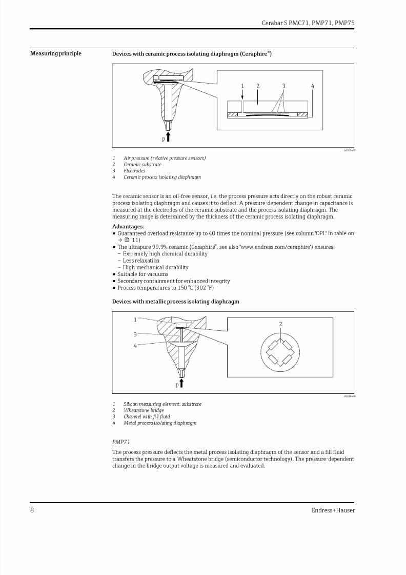
Measuring principle Devices with ceramic process isolating diaphragm (Ceraphire®)
1 2 3 4
p
A0020465
1 Air pressure (relative pressure sensors)2 Ceramic substrate3 Electrodes4 Ceramic process isolating diaphragm
The ceramic sensor is an oil-free sensor, i.e. the process pressure acts directly on the robust ceramicprocess isolating diaphragm and causes it to deflect. A pressure-dependent change in capacitance ismeasured at the electrodes of the ceramic substrate and the process isolating diaphragm. Themeasuring range is determined by the thickness of the ceramic process isolating diaphragm.
Advantages:• Guaranteed overload resistance up to 40 times the nominal pressure (see column "OPL" in table on
→ 11)• The ultrapure 99.9% ceramic (Ceraphire®, see also "www.endress.com/ceraphire") ensures:
– Extremely high chemical durability – Less relaxation– High mechanical durability
• Suitable for vacuums
• Secondary containment for enhanced integrity • Process temperatures to 150 °C (302 °F)
Devices with metallic process isolating diaphragm
p
1
3
4
2
A0016448
1 Silicon measuring element, substrate2 Wheatstone bridge3 Channel with fill fluid4 Metal process isolating diaphragm
PMP71
The process pressure deflects the metal process isolating diaphragm of the sensor and a fill fluidtransfers the pressure to a Wheatstone bridge (semiconductor technology). The pressure-dependent
change in the bridge output voltage is measured and evaluated.
7/24/2019 Cerabar S PMC71, PMP71, PMP75
http://slidepdf.com/reader/full/cerabar-s-pmc71-pmp71-pmp75 9/116
Cerabar S PMC71, PMP71, PMP75
Endress+Hauser 9
Advantages:• Can be used for process pressures up to 700 bar (10 500 psi)• High long-term stability • Guaranteed overload resistance up to 4 times the nominal pressure• Secondary containment for enhanced integrity • Significantly reduced thermal effect e.g. compared to diaphragm seal systems with capillaries
PMP75
The operating pressure acts on the process isolating diaphragm of the diaphragm seal and istransferred to the process isolating diaphragm of the sensor by a diaphragm seal fill fluid. Theprocess isolating diaphragm is deflected and a fill fluid transfers the pressure to a resistancemeasuring bridge. The pressure-dependent change in the bridge output voltage is measured andevaluated.
Advantages:• Depending on the version, can be used for process pressures up to 400 bar (6 000 psi) and extreme
process temperatures• High long-term stability • Guaranteed overload resistance up to 4 times the nominal pressure• Secondary containment for enhanced integrity
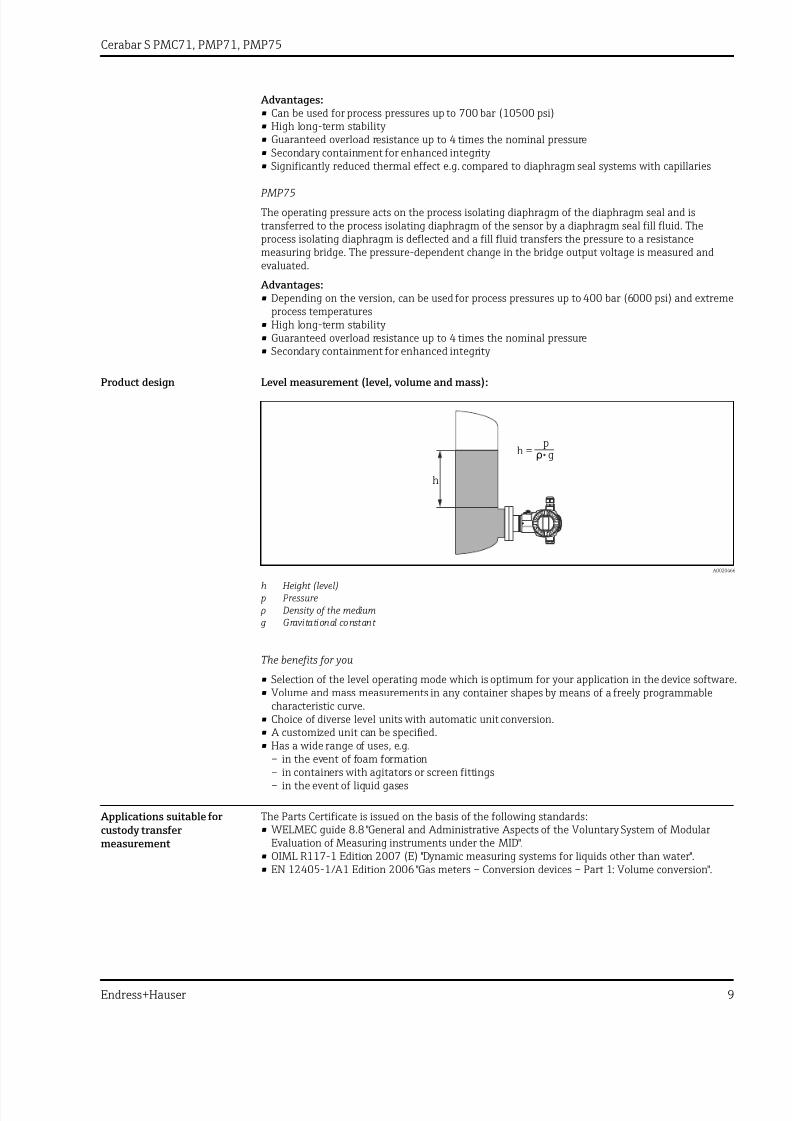
Product design Level measurement (level, volume and mass):
h =p
ρ g
h
A0020466
h Height (level)p Pressure
ρ Density of the mediumg Gravitational constant
The benefits for you
• Selection of the level operating mode which is optimum for your application in the device software.• Volume and mass measurements in any container shapes by means of a freely programmable
characteristic curve.• Choice of diverse level units with automatic unit conversion.
• A customized unit can be specified.• Has a wide range of uses, e.g.
– in the event of foam formation– in containers with agitators or screen fittings– in the event of liquid gases
Applications suitable forcustody transfermeasurement
The Parts Certificate is issued on the basis of the following standards:• WELMEC guide 8.8 "General and Administrative Aspects of the Voluntary System of Modular
Evaluation of Measuring instruments under the MID".• OIML R117-1 Edition 2007 (E) "Dynamic measuring systems for liquids other than water".• EN 12405-1/A1 Edition 2006 "Gas meters – Conversion devices – Part 1: Volume conversion".
7/24/2019 Cerabar S PMC71, PMP71, PMP75
http://slidepdf.com/reader/full/cerabar-s-pmc71-pmp71-pmp75 10/116
Cerabar S PMC71, PMP71, PMP75
10 Endress+Hauser
Communication protocol • 4 to 20 mA with HART communication protocol• PROFIBUS PA
– The Endress+Hauser devices meet the requirements of the FISCO model.– Due to a low current consumption of 13 mA ± 1 mA, the following number of devices can be
operated on one bus segment if installing as per FISCO: up to 7 devices for Ex ia, CSA IS and FMIS applications or up to 27 devices for all other applications e.g. in non-hazardous areas, Ex nA
etc.Further information on PROFIBUS PA can be found in Operating Instructions BA00034S
"PROFIBUS DP/PA: Guidelines for planning and commissioning" and in the PNO Guideline.• FOUNDATION Fieldbus
– The Endress+Hauser devices meet the requirements of the FISCO model.– Due to a low current consumption of 15.5 mA ± 1 mA, the following number of devices can be
operated on one bus segment if installing as per FISCO: up to 6 devices for Ex ia, CSA IS and FMIS applications or up to 24 devices for all other applications e.g. in non-hazardous areas, Ex nA etc.Further information on FOUNDATION Fieldbus, such as requirements for bus systemcomponents, can be found in Operating Instructions BA00013S "FOUNDATION FieldbusOverview".

7/24/2019 Cerabar S PMC71, PMP71, PMP75
http://slidepdf.com/reader/full/cerabar-s-pmc71-pmp71-pmp75 11/116
Cerabar S PMC71, PMP71, PMP75
Endress+Hauser 11
Input
Measured variable Measured process variables
• Absolute pressure• Gauge pressure
Calculated process variables
Level (level, volume or mass)
Measuring range PMC71 – with ceramic process isolating diaphragm (Ceraphire®) for gauge pressure
Nominal value Range limit Lowestcalibratablespan 1)
MWP OPL Vacuum resistance Option 2)
lower (LRL) upper (URL)
[bar (psi)] [bar (psi)] [bar (psi)] [bar (psi)] [bar (psi)] [barabs (psiabs)]
100 mbar (1.5 psi) –0.1 (–1.5) +0.1 (+1.5) 0.005 (0.075) 2.7 (40.5) 4 (60) 0.7 (10.5) 1C
250 mbar (3.75 psi) –0.25 (–4) +0.25 (+4) 0.005 (0.075) 3.3 (49.5) 5 (75) 0.5 (7.5) 1E400 mbar (6 psi) –0.4 (–6) +0.4 (+6) 0.005 (0.075) 5.3 (79.5) 8 (120) 0 1F
1 bar (15 psi) –1 (–15) +1 (+15) 0.01 (0.15) 6.7 (100.5) 10 (150) 0 1H
2 bar (30 psi) –1 (–15) +2 (+30) 0.02 (0.3) 12 (180) 18 (270) 0 1K
4 bar (60 psi) –1 (–15) +4 (+60) 0.04 (0.6) 16.7 (250.5) 25 (375) 0 1M
10 bar (150 psi) –1 (–15) +10 (+150) 0.1 (1.5) 26.7 (400.5) 40 (600) 0 1P
40 bar (600 psi) –1 (–15) +40 (+600) 0.4 (6) 40 (600) 60 (900) 0 1S
1) Turn down > 100:1 on request or can be set at the device2) Product Configurator, order code for "Sensor range; Sensor over pressure limit"
PMC71 – with ceramic process isolating diaphragm (Ceraphire®) for absolute pressure
Nominal value Range limit Lowestcalibratablespan 1)
MWP OPL Vacuum resistance Option 2)
lower (LRL) upper (URL)
[bar (psi)] [bar (psi)] [bar (psi)] [bar (psi)] [bar (psi)] [barabs (psiabs)]
100 mbar (1.5 psi) 0 +0.1 (+1.5) 0.005 (0.075) 2.7 (40.5) 4 (60) 0 2C
250 mbar (3.75 psi) 0 +0.25 (+4) 0.005 (0.075) 3.3 (49.5) 5 (75) 0 2E
400 mbar (6 psi) 0 +0.4 (+6) 0.005 (0.075) 5.3 (79.5) 8 (120) 0 2F
1 bar (15 psi) 0 +1 (+15) 0.01 (0.15) 6.7 (100.5) 10 (150) 0 2H
2 bar (30 psi) 0 +2 (+30) 0.02 (0.3) 12 (180) 18 (270) 0 2K
4 bar (60 psi) 0 +4 (+60) 0.04 (0.6) 16.7 (250.5) 25 (375) 0 2M
10 bar (150 psi) 0 +10 (+150) 0.1 (1.5) 26.7 (400.5) 40 (600) 0 2P
40 bar (600 psi) 0 +40 (+600) 0.4 (6) 40 (600) 60 (900) 0 2S
1) Turn down > 100:1 on request or can be set at the device2) Product Configurator, order code for "Sensor range; Sensor over pressure limit"

7/24/2019 Cerabar S PMC71, PMP71, PMP75
http://slidepdf.com/reader/full/cerabar-s-pmc71-pmp71-pmp75 12/116
Cerabar S PMC71, PMP71, PMP75
12 Endress+Hauser
PMP71 and PMP75 – metallic process isolating diaphragm for gauge pressure
Nominal value Range limit Lowestcalibratablespan 1)
MWP OPL Vacuum resistance 2) Option 3)
lower (LRL) upper (URL) Synthetic oil/Inert oil
[bar (psi)] [bar (psi)] [bar (psi)] [bar (psi)] [bar (psi)] [barabs (psiabs)]
400 mbar (6 psi) –0.4 (–6) +0.4 (+6) 0.005 (0.075) 4 (60) 6 (90)
0.01/0.04 (0.15/0.6)
1F
1 bar (15 psi) –1 (–15) +1 (+15) 0.01 (0.15) 6.7 (100) 10 (150) 1H
2 bar (30 psi) –1 (–15) +2 (+30) 0.02 (0.3) 13.3 (200) 20 (300) 1K
4 bar (60 psi) –1 (–15) +4 (+60) 0.04 (0.6) 18.7 (280.5) 28 (420) 1M
10 bar (150 psi) –1 (–15) +10 (+150) 0.1 (1.5) 26.7 (400.5) 40 (600) 1P
40 bar (600 psi) –1 (–15) +40 (+600) 0.4 (6) 100 (1500) 160 (2400) 1S
100 bar (1 500 psi) –1 (–15) +100 (+1500) 1.0 (15) 100 (1500) 400 (6000) 1U
400 bar (6 000 psi) –1 (–15) +400 (+6000) 4.0 (60) 400 (6000) 600 (9000) 1W
700 bar (10 500 psi) 4)
–1 (–15) +700 (+10500) 7.0 (105) 700 (10500) 1050 (15750) 1X
1) Turn down > 100:1 on request or can be set at the device2) The vacuum resistance applies to the measuring cell under reference operating conditions. The pressure and temperature application limits of the
selected filling oil must also be observed for the PMP75 .3) Product Configurator, order code for "Sensor range; Sensor over pressure limit"4) PMP71 only, PMP75 on request
PMP71 and PMP75 – metallic process isolating diaphragm for absolute pressure
Nominal value Range limit Lowestcalibratablespan 1)
MWP OPL Vacuum resistance 2) Option 3)
lower (LRL) upper (URL) Synthetic oil/Inert oil
[bar (psi)] [bar (psi)] [bar (psi)] [bar (psi)] [bar (psi)] [barabs (psiabs)]
400 mbar (6 psi) 0 +0.4 (+6) 0.005 (0.075) 4 (60) 6 (90)
0.01/0.04 (0.15/0.6)
2F
1 bar (15 psi) 0 +1 (+15) 0.01 (0.15) 6.7 (100) 10 (150) 2H
2 bar (30 psi) 0 +2 (+30) 0.02 (0.3) 13.3 (200) 20 (300) 2K
4 bar (60 psi) 0 +4 (+60) 0.04 (0.6) 18.7 (280.5) 28 (420) 2M
10 bar (150 psi) 0 +10 (+150) 0.1 (1.5) 26.7 (400.5) 40 (600) 2P
40 bar (600 psi) 0 +40 (+600) 0.4 (6) 100 (1500) 160 (2400) 2S
100 bar (1 500 psi) 0 +100 (+1500) 1.0 (15) 100 (1500) 400 (6000) 2U
400 bar (6 000 psi) 0 +400 (+6000) 4.0 (60) 400 (6000) 600 (9000) 2W
700 bar (10 500 psi) 4) 0 +700 (+10500) 7.0 (105) 700 (10500) 1050 (15750) 2X
1) Turn down > 100:1 on request or can be set at the device2) The vacuum resistance applies to the measuring cell under reference operating conditions. The pressure and temperature application limits of the
selected filling oil must also be observed for the PMP75 .3) Product Configurator, order code for "Sensor range; Sensor over pressure limit"4) PMP71 only, PMP75 on request

7/24/2019 Cerabar S PMC71, PMP71, PMP75
http://slidepdf.com/reader/full/cerabar-s-pmc71-pmp71-pmp75 13/116
Cerabar S PMC71, PMP71, PMP75
Endress+Hauser 13
PMP71 - metallic process isolating diaphragms for absolute pressure with MID parts certificate
Nominal value
Range limit Min. WP for gasapplications suitablefor custody transfermeasurement
Min. WP for liquidapplications suitablefor custody transfermeasurement
MWP OPL Vacuumresistance 1)
Option 2)
lower(LRL) 3)
upper(URL) 4)
Silicone oil/Inert oil
[bar (psi)] [bar (psi)] [bar (psi)] [bar (psi)] [bar (psi)] [bar (psi)] [bar(psi)]
[bar (psi)]
10 (150) 0 +10 (150) 0.5 (7.5) 0.5 (7.5) 26.7(400.5)
40 (600) 0.01/0.04(0.15/1)
MP
50 (750) 0 +50 (750) 10 (150) 2.5 (37.5) 100(1500)
400(6000)
0.01/0.04(0.15/1)
MT
100 (1500) 0 +100(1500)
5 (75) 5 (75) 100(1500)
400(6000)
0.01/0.04(0.15/1)
MU
1) The vacuum resistance applies to the measuring cell under reference operating conditions2) Product Configurator, order code for "Sensor range; Sensor over pressure limit"3) By default, the device is set to a lower sensor limit of 0 bar. Please specify in the order if the lower range limit is to be set to a different default
value.4) Max. WP for gas and liquid applications suitable for custody transfer measurement

7/24/2019 Cerabar S PMC71, PMP71, PMP75
http://slidepdf.com/reader/full/cerabar-s-pmc71-pmp71-pmp75 14/116
Cerabar S PMC71, PMP71, PMP75
14 Endress+Hauser
Output
Output signal • 4 to 20 mA with superimposed digital communication protocol HART, 2-wire• Digital communication signal PROFIBUS PA (Profile 3.0), 2-wire
– Signal coding: Manchester Bus Powered (MBP): Manchester II
– Transmission rate: 31.25 KBit/s voltage mode• Digital communication signal FOUNDATION Fieldbus, 2-wire– Signal coding: Manchester Bus Powered (MBP): Manchester II– Transmission rate: 31.25 KBit/s voltage mode
Output Internal + LCD External + LCD Internal
on on
off off
damp.
damp.
Display Display
Sensor Sensor
HART HARTR R
FIELDCOMMUNICATION PROTOCOL FIELD COMMUNICATION PROTOCOL
SW
/min
SW
/min
E+ –E+ –
A0021280
Option 1)
4 to 20mA HART B A C
4 to 20mA HART, Li=0 E D F
PROFIBUS PA N M O
FOUNDATION Fieldbus Q P R
1) Product Configurator order code for "Display, operation: "
Signal range 4 to 20 mA 3.8 mA to 20.5 mA
Signal on alarm As per NAMUR NE43
4 to 20 mA HART
• Max. alarm: Can be set between 21 to 23 mA (factory setting: 22 mA)• Hold measured value: last measured value is held• Min. alarm: 3.6 mA
PROFIBUS PA
Can be set in the Analog Input Block.
Options:• Last Valid Out Value (factory setting)• Fail Safe Value• Status bad
FOUNDATION FieldbusCan be set in the Analog Input Block.
Options:• Last Good Value• Fail Safe Value (factory setting)• Wrong Value

7/24/2019 Cerabar S PMC71, PMP71, PMP75
http://slidepdf.com/reader/full/cerabar-s-pmc71-pmp71-pmp75 15/116
Cerabar S PMC71, PMP71, PMP75
Endress+Hauser 15
Maximum load - 4 to 20 mA HART
In order to guarantee sufficient terminal voltage in two-wire devices, a maximum load resistance R (including line resistance) must not be exceeded depending on the supply voltage U0 of the supply unit. In the following load diagrams, observe the position of the jumper and the explosion protection:
U – 11.5 V
U – 12 V
23 mA
23 mA
[ ]
[ ]
30
30
20
20
11.5
12
40
40
45
45
1239
1217
1456
1434
804
782
369
347
Test
B
B
U – 10.5 V
U – 11 V
R
R
L
L
max
max
23 mA
23 mA
30
30
20
20
10.5
11
U
U
U
U
[V]
[V]
[V]
[V]
40
40
45
45
1282
1260
1500
1478
847
826
413
391
[ ]
[ ]
R
R
L
L
max
max
Test
4
4
A
A
1
2
3
1
2
3
R
R
L
L
max
max
4
4
R
R
L
L
max
max
A0020467
A Jumper for 4 to 20 mA test signal set to "Non-test" position B Jumper for 4 to 20 mA test signal set to "Test" position1 Power supply 10.5 (11.5) to 30 V DC for 1/2 G, 1 GD, 1/2 GD, FM IS, CSA IS, IECEx ia, NEPSI Ex ia2 Power supply 10.5 (11.5) to 45 V DC for devices for non-hazardous areas, 1/2 D, 1/3 D, 2 G Ex d, 3 G Ex nA,
FM XP, FM DIP, FM NI, CSA XP, CSA dust ignition-proof, NEPSI Ex d3 Power supply 11 (12) to 45 V DC for PMC71, Ex d[ia], NEPSI Ex d[ia]4 R Lmax maximum load resistance
U Supply voltage
When operating via a handheld terminal or via a PC with an operating program, a minimumcommunication resistance of 250 Ω must be taken into account.
Dead time, time constant Presentation of the dead time and the time constant:

7/24/2019 Cerabar S PMC71, PMP71, PMP75
http://slidepdf.com/reader/full/cerabar-s-pmc71-pmp71-pmp75 16/116
Cerabar S PMC71, PMP71, PMP75
16 Endress+Hauser
I
63 %
100 %
tt1 t2
90 %
t3
A0019786
Dynamic behavior:current output
Type Measuring cell Dead time (t1) [ms] Time constant T63 (t2) [ms] Time constant T90 (t3) [ms]
PMC71 Max. All 90 120 276
PMP71 Max. • 400 mbar (6 psi)• ≥ 1 bar (15 psi)
45 • 70• 35
• 161• 81
PMP75 Max. PMP71 + influence of the diaphragm seal
Dynamic behavior: Digitaloutput (HART electronics)
A typical burst rate of 300 ms results in the following behavior:
Type Measuring cell Dead time (t1) [ms] Dead time (t1) [ms] +Time constant T63 (t2) [ms]
Dead time (t1) [ms] +Time constant T90 (t3) [ms]
PMC71 Min. All 250 370 436
Max. 1050 1170 1236
PMP71 Min. • 400 mbar (6 psi)
• ≥ 1 bar (15 psi)
205 • 275
• 240
• 321
• 241Max. • 400 mbar (6 psi)
• ≥ 1 bar (15 psi)1005 • 1075
• 1040• 1121• 1041
PMP75 Max. PMP71 + influence of the diaphragm seal
Reading cycle
• Acyclic: max. 3/s, typically 1/s (depending on command # and number of preambles)• Cyclic (burst): max. 3/s, typically 2/s
The device commands the BURST MODE functionality for cyclical value transmission via the HARTcommunication protocol.
Cycle time (update time)Cyclic (burst): min. 300 ms
Response time
• Acyclic: min. 330 ms, typically 590 ms (depending on command # and number of preambles)• Cyclic (burst): min. 160 ms, typically 350 ms (depending on command # and number of
preambles)
Dynamic behavior:PROFIBUS PA
A typical PLC cycle time of 1 s results in the following behavior:
Type Measuring cell Dead time (t1) [ms] Dead time (t1) [ms] +Time constant T63 (t2) [ms]
Dead time (t1) [ms] +Time constant T90 (t3) [ms]
PMC71 Min. All 125 245 311
Max. 1325 1445 1511

7/24/2019 Cerabar S PMC71, PMP71, PMP75
http://slidepdf.com/reader/full/cerabar-s-pmc71-pmp71-pmp75 17/116
Cerabar S PMC71, PMP71, PMP75
Endress+Hauser 17
Type Measuring cell Dead time (t1) [ms] Dead time (t1) [ms] +Time constant T63 (t2) [ms]
Dead time (t1) [ms] +Time constant T90 (t3) [ms]
PMP71 Min. • 400 mbar (6 psi)• ≥ 1 bar (15 psi)
80 • 150• 115
• 196• 116
Max. • 400 mbar (6 psi)
• ≥ 1 bar (15 psi)
1280 • 1350
• 1315
• 1396
• 1316PMP75 Max. PMP71 + influence of the diaphragm seal
Reading cycle (PLC)
• Acyclic: Typically 25/s• Cyclic: Typically 30/s (depending on the number and type of the function blocks used in the
closed-control loop)
Cycle time (update time)
Min. 200 ms
The cycle time in a bus segment in cyclic data communication depends on the number of devices, on
the segment coupler used and on the internal PLC cycle time. A new measured value can bedetermined up to five times a second.
Response time
• Acyclic: Approx. 60 ms to 70 ms (depending on Min. Slave Interval)• Cyclic: Approx. 10 ms to 13 ms (depending on Min. Slave Interval)
Dynamic behavior:FOUNDATION Fieldbus
A typical configuration for the macro cycle time (host system) of 1 s results in the followingbehavior:
Type Measuring cell Dead time (t1) [ms] Dead time (t1) [ms] +Time constant T63 (t2) [ms]
Dead time (t1) [ms] +Time constant T90 (t3) [ms]
PMC71 Min. All 135 255 321Max. 1135 1255 1321
PMP71 Min. • 400 mbar (6 psi)• ≥ 1 bar (15 psi)
90 • 160• 125
• 206• 126
Max. • 400 mbar (6 psi)• ≥ 1 bar (15 psi)
1090 • 1160• 1125
• 1206• 1126
PMP75 Max. PMP71 + influence of the diaphragm seal
Reading cycle
• Acyclic: Typically 10/s
• Cyclic: Max. 10/s (depending on the number and type of the function blocks used in the closed-control loop)
Cycle time (update time)
Cyclic: Min. 100 ms
Response time
• Acyclic: Typically 100 ms (for standard bus parameter settings)• Cyclic: Max. 20 ms (for standard bus parameter settings)
Damping A damping affects all outputs (output signal, display):• Via onsite display, handheld terminal or PC with operating program, continuous from 0 to 999 s• Also for HART and PROFIBUS PA: Via DIP switch on the electronic insert,
switch position "on" = set value and "off"• Factory setting: 2 s

7/24/2019 Cerabar S PMC71, PMP71, PMP75
http://slidepdf.com/reader/full/cerabar-s-pmc71-pmp71-pmp75 18/116
Cerabar S PMC71, PMP71, PMP75
18 Endress+Hauser
Alarm current Description Option 1)
Min alarm current J
HART burst mode PV
Min alarm current + HART burst mode PV
1) Product Configurator, order code for "Additional options 1" and "Additional options 2"
Firmware version Description Option 1)
02.20.zz, HART, DevRev22 72
02.11.zz, HART, DevRev21 73
04.00.zz, FF, DevRev07 74
04.01.zz, PROFIBUS PA, DevRev03 75
02.10.zz, HART, DevRev21 76
03.00.zz, FF, DevRev06 77
04.00.zz, PROFIBUS PA 78
1) Product Configurator order code for "Firmware version"
Protocol-specific data HART
Manufacturer ID 17 (11 hex)
Device type code 24 (18 hex)
Device revision • 21 (15 hex) - SW version 02.1y.zz - HART specification 5• 22 (16 hex) - SW version 02.2y.zz - HART specification 7
HART specification • 5
• 7DD revision • 4 (Russian in language selection) for device revision 21
• 3 (Dutch in language selection) for device revision 21• 1 for device revision 22
Device description files (DTM, DD) Information and files at:
• www.endress.com• www.hartcomm.org
HART load Min. 250 Ω
HART device variables The measured values are assigned to the device variables as fol lows:
Measured values for PV (primary variable)• Pressure• Level
• Tank contentMeasured values for SV, TV (second and third variable)Pressure
Measured values for QV (fourth variable)Temperature
Supported functions • Burst mode• Additional transmitter status• Device locking• Alternative operating modes
PROFIBUS PA
Manufacturer ID 17 (11 hex)
Identification number 1541 hex

7/24/2019 Cerabar S PMC71, PMP71, PMP75
http://slidepdf.com/reader/full/cerabar-s-pmc71-pmp71-pmp75 19/116
Cerabar S PMC71, PMP71, PMP75
Endress+Hauser 19
Profile version 3.0• SW version 03.00.zz• SW version 04.00.zz
3.02SW version 04.01.zz ( device revision 3)Compatibility with SW version 03.00.zz and higher.
GSD revision • 4 (SW version 3.00.zz and 4.00.zz)• 5 (device revision 3)
DD revision • 1 (SW version 3.00.zz and 4.00.zz)• 1 (device revision 3)
GSD file Information and files at:
• www.endress.com• www.profibus.org
DD files
Output values Measured value for PV (via Analog Input Function Block)• Pressure• Level•• Tank content
Measured value for SV • Pressure• Temperature
Input values Input value sent from PLC, can be shown on display
Supported functions • Identification & maintenance Simplest device identifier on thecontrol system and nameplate
• Condensed status (only with Profile Version 3.02)• Automatic ID number adjustment and switchable to the following ID
numbers (only with Profile Version 3.02):– 9700: Profile-specific transmitter identification number with the
"Classic" or "Condensed" status".– 1501: Compatibility mode for the old Cerabar S generation
(PMC731, PMP731, PMC631, PMP635).
– 1541: Identification number for the new Cerabar S generation(PMC71, PMP71, PMP75).• Device locking: The device can be locked by hardware or software.
FOUNDATION Fieldbus
Manufacturer ID 452B48 hex
Device type 1007 hex
Device revision • 6 - SW version 03.00.zz• 7 - SW version 04.00.zz (FF-912)
DD revision • 3 (device revision 6)
• 2 (device revision 7)CFF revision • 4 (device revision 6)
• 1 (device revision 7)
DD files Information and files at:
• www.endress.com• www.fieldbus.org
CFF files
Device tester version (ITK version) • 5.0 (device revision 6)• 6.01 (device revision 7)
Number of ITK test campaign • IT054600 (Device Revision 6)• IT085500 (Device Revision 7)
Link Master (LAS) capable Yes
Choice of "Link Master" and "BasicDevice" Yes, factory setting is Basic Device
Node address Factory setting: 247 (F7 hex)

7/24/2019 Cerabar S PMC71, PMP71, PMP75
http://slidepdf.com/reader/full/cerabar-s-pmc71-pmp71-pmp75 20/116
Cerabar S PMC71, PMP71, PMP75
20 Endress+Hauser
Supported functions Field diagnostics profile (only with FF912)
The following methods are supported:• Restart• Configure error as warning or alarm• HistoROM• Peakhold
• Alarm info• Sensor trim
Number of VCRs • 44 (device revision 6)• 24 (device revision 7)
Number of link objects in VFD 50
Virtual communication references (VCRs)
Device revision 6 Device revision 7
Permanent entries 44 1
Client VCRs 0 0
Server VCRs 5 10
Source VCRs 8 43
Sink VCRs 0 0
Subscriber VCRs 12 43
Publisher VCRs 19 43
Link settings
Device revision 6 Device revision 7
Slot time 4 4
Min. Inter PDU delay 12 10
Max. response delay 10 10
Transducer Blocks
Block Content Output values
TRD1 Block Contains all parameters related to themeasurement
• Pressure or level (channel 1)• Process temperature (channel 2)
Service Block Contains service information • Pressure after damping (channel 3)• Pressure peakhold indicator (channel 4)• Totalizer for max. pressure exceeded (channel 5)
Diagnostic Block Contains diagnostic information Error code via DI channels (channel 0 to 16)
Display Block Contains parameters to configure theonsite display
No output values

7/24/2019 Cerabar S PMC71, PMP71, PMP75
http://slidepdf.com/reader/full/cerabar-s-pmc71-pmp71-pmp75 21/116
Cerabar S PMC71, PMP71, PMP75
Endress+Hauser 21
Function blocks
Block Content Numberblocks
Execution time Functionality
DeviceRevision 6
DeviceRevision 7
DeviceRevision 6
DeviceRevision 7
Resource Block This block contains all the data that uniquely identifies the device; it isan electronic version of a nameplate for the device.
1 enhanced enhanced
Analog InputBlock 1
Analog InputBlock 2
The AI Block receives the measuring data from the Sensor Block,(selectable via a channel number) and makes the data available toother function blocks at its output. Enhancement: Digital outputs forprocess alarms, fail safe mode
2 45 ms 45 ms(withouttrend andalarmreports)
enhanced enhanced
Digital InputBlock
This block contains the discrete data of the Diagnose Block (selectable via a channel number 0 to 16) and provides them for other blocks at
the output.
1 40 ms 30 ms standard enhanced
Digital OutputBlock
This block converts the discrete input and thus initiates an action(selectable via a channel number) in the DP Flow Block or in theService Block. Channel 1 resets the max. overpressure meter.
1 60 ms 40 ms standard enhanced
PID Block This block is used as a proportional-integral-derivative controller andcan be used universally for closed-loop-control in the field. It enablescascade mode and feedforward control. Input IN can be indicated onthe display. The selection is performed in the Display Block (DISPLAY_MAIN_LINE_CONTENT).
1 120 ms 70 ms standard enhanced
ArithmeticBlock
This block is designed to permit simple use of popular measurementmath functions. The user does not have to know how to writeequations. The math algorithm is selected by name, chosen by theuser for the function to be performed.
1 50 ms 40 ms standard enhanced
Input SelectorBlock
The Input Selector Block facilitates the selection of up to four inputsand generates an output based on the configured action. This block normally receives its inputs from AI Blocks. The block performsmaximum, minimum, average and ‘first good’ signal selection. Inputs
IN1 to IN4 can be indicated on the display. The selection is performedin the Display Block (DISPLAY_MAIN_LINE_CONTENT).
1 35 ms 35 ms standard enhanced
SignalCharacterizerBlock
The Signal Characterizer Block has two sections, each with an outputthat is a non-linear function of the respective input. The non-linearfunction is generated by a single look-up table with 21 arbitrary x-y pairs.
1 30 ms 40 ms standard enhanced
Integrator Block The Integrator Block integrates a variable as a function of the time oraccumulates the counts from a Pulse Input Block. The block can beused as a totalizer that counts up until a reset, or as a batch totalizer
whereby the integrated value is compared against a target valuegenerated before or during the control routine and generates a binary signal when the target value is reached.
1 35 ms 40 ms standard enhanced
Analog Alarm
Block
This block contains all process alarm conditions (working like a
comparator) and represents them at the output.
1 35 ms 35 ms standard enhanced
Additional function block information:
Instantiatable function blocks YES YES
Number of additional instantiatable function blocks 11 5

7/24/2019 Cerabar S PMC71, PMP71, PMP75
http://slidepdf.com/reader/full/cerabar-s-pmc71-pmp71-pmp75 22/116
Cerabar S PMC71, PMP71, PMP75
22 Endress+Hauser
Power supply
LWARNING
Electrical safety is compromised by an incorrect connection.‣ When using the measuring device in hazardous areas, installation must comply with the
corresponding national standards and regulations and the Safety Instructions or Installation or
Control Drawings → 112.‣ All explosion protection data are given in separate documentation which is available upon
request. The Ex documentation is supplied as standard with all devices approved for use inexplosion hazardous areas → 112.
‣ Devices with integrated overvoltage protection must be grounded → 26.‣ Protective circuits against reverse polarity, HF influences and overvoltage peaks are integrated.
Terminal assignment 4 to 20 mA HART
4... 20mA Test
Test
Test
4... 20mA Test
1
8
67
2
3
4
5
A0019989
1 Housing2 Supply voltage3 4 to 20 mA4 Devices with integrated overvoltage protection are labeled "OVP" (overvoltage protection) here.5 External ground terminal6 4 to 20 mA test signal between positive and test terminal7 Internal ground terminal8 Jumper for 4 to 20 mA test signal
PROFIBUS PA and FOUNDATION Fieldbus
1
4
5
2
3
A0020158
1 Housing2 Supply voltage3 Devices with integrated overvoltage protection are labeled "OVP" (overvoltage protection) here.4 External ground terminal5 Internal ground terminal

7/24/2019 Cerabar S PMC71, PMP71, PMP75
http://slidepdf.com/reader/full/cerabar-s-pmc71-pmp71-pmp75 23/116
Cerabar S PMC71, PMP71, PMP75
Endress+Hauser 23
Supply voltage 4 to 20 mA HART
Electronic version Jumper for 4 to 20 mA test signal in"Test" position (delivery status)
Jumper for 4 to 20 mA test signal in"Non-test" position
Version for non-
hazardous area
11.5 to 45 V DC 10.5 to 45 V DC
Intrinsically safe 11.5 to 30 V DC 10.5 to 30 V DC
• Other types ofprotection
• Devices withoutcertificate
11.5 to 45 V DC(versions with 35 V DC plug-inconnection)
10.5 to 45 V DC(versions with 35 V DC plug-inconnection)
Measuring a 4 to 20 mA test signal
A 4 to 20 mA test signal may be measured via the positive and test terminal without interruptingthe measurement. The minimum supply voltage of the device can be reduced by simply changing theposition of the jumper. As a result, operation is also possible with lower voltage sources. Observe theposition of the jumper in accordance with the following table.
Jumper position for testsignal
Description
Test
A0019992
• Measurement of 4 to 20 mA test signal via the positive and test terminal:Possible. (Thus, the output current can be measured without interruption viathe diode.)
• Delivery status• Minimum supply voltage: 11.5 V DC
Test
A0019993
• Measurement of 4 to 20 mA test signal via positive and test terminal: Notpossible.
• Minimum supply voltage: 10.5 V DC
PROFIBUS PA
• Version for non-hazardous areas: 9 to 32 V DC• Ex ia: 10.5 to 30 V DC
FOUNDATION Fieldbus
• Version for non-hazardous areas: 9 to 32 V DC• Ex ia: 10.5 to 30 V DC
Current consumption • PROFIBUS PA: 13 mA ±1 mA, switch-on current corresponds to IEC 61158-2, Clause 21• FOUNDATION Fieldbus: 15.5 mA ±1 mA, switch-on current corresponds to IEC 61158-2, Clause
21

7/24/2019 Cerabar S PMC71, PMP71, PMP75
http://slidepdf.com/reader/full/cerabar-s-pmc71-pmp71-pmp75 24/116
Cerabar S PMC71, PMP71, PMP75
24 Endress+Hauser
Electrical connection PROFIBUS PA
The digital communication signal is transmitted to the bus via a 2-wire connection. The bus alsoprovides the power supply. For further information on the network structure and grounding, and forfurther bus system components such as bus cables, see the relevant documentation, e.g. OperatingInstructions BA00034S "PROFIBUS DP/PA: Guidelines for planning and commissioning" and the
PNO Guideline.
FOUNDATION Fieldbus
The digital communication signal is transmitted to the bus via a 2-wire connection. The bus alsoprovides the power supply. For further information on the network structure and grounding and forfurther bus system components such as bus cables, see the relevant documentation, e.g. OperatingInstructions BA00013S "FOUNDATION Fieldbus Overview" and the FOUNDATION Fieldbus Guideline.
Terminals • Supply voltage and internal ground terminal: 0.5 to 2.5 mm2 (20 to 14 AWG)• External ground terminal: 0.5 to 4 mm2 (20 to 12 AWG)
Cable entries Approval Cable gland Clamping area
Standard, II 1/2 G Ex ia, IS Plastic M20x1.5 5 to 10 mm (0.2 to 0.39 in) ATEX II 1/2 D, II 1/3 D, II 1/2 GD Ex ia,
II 1 GD Ex ia, II 3 G Ex nA Metal M20x1.5 (Ex e) 7 to 10.5 mm (0.28 to 0.41 in)
For additional technical data, see section on housing → 46
Connector Devices with Harting plug Han7D
Han7D
–+
+ –
– +
1
5
4
6
7
8
2
3
A B
A0019990
A Electrical connection for devices with Harting plug Han7D B View of the plug-in connection on the device
Material: CuZn, gold-plated plug-in jack and plug
Cable version connection
–
++
PE
–
1 2 3 4
A0019991
1 rd = red2 bk = black
3 gnye = green4 4 to 20 mA

7/24/2019 Cerabar S PMC71, PMP71, PMP75
http://slidepdf.com/reader/full/cerabar-s-pmc71-pmp71-pmp75 25/116
Cerabar S PMC71, PMP71, PMP75
Endress+Hauser 25
Devices with M12 plug
21
34
A0011175
1 Signal +2 Not assigned3 Signal –4 Ground
Endress+Hauser offers the following accessories for devices with an M12 plug:
Plug-in jack M 12x1, straight• Material: Body PA; coupling nut CuZn, nickel-plated
• Degree of protection (fully locked): IP67• Order number: 52006263
Plug-in jack M 12x1, elbowed• Material: Body PBT/PA; coupling nut GD-Zn, nickel-plated• Degree of protection (fully locked): IP67• Order number: 71114212
Cable 4 x 0.34 mm2 (20 AWG) with M12 socket, elbowed, screw plug, length 5 m (16 ft)• Material: Body PUR; coupling nut CuSn/Ni; cable PVC• Degree of protection (fully locked): IP67• Order number: 52010285
Devices with 7/8" plug
2
1
4
3
A0011176
1 Signal –2 Signal +3 Not assigned4 Shielding
External thread: 7/8 - 16 UNC• Material: 316L (1.4401)• Degree of protection: IP68
Cable specification HART
• Endress+Hauser recommends using shielded, twisted-pair two-wire cables.• Cable outer diameter: 5 to 9 mm (0.2 to 0.35 in) depending on the cable entry used → 24
PROFIBUS PA
Use a twisted, shielded twin-core cable, preferably cable type A.
For further information regarding cable specifications, see the Operating Instructions
BA00034S "PROFIBUS DP/PA: Guidelines for planning and commissioning", the PNO guideline2.092 "PROFIBUS PA User and Installation Guideline" and IEC 61158-2 (MBP).

7/24/2019 Cerabar S PMC71, PMP71, PMP75
http://slidepdf.com/reader/full/cerabar-s-pmc71-pmp71-pmp75 26/116
Cerabar S PMC71, PMP71, PMP75
26 Endress+Hauser
FOUNDATION Fieldbus
Use a twisted, shielded twin-core cable, preferably cable type A.
For further information on the cable specifications, see Operating Instructions BA00013S "FOUNDATION Fieldbus Overview", FOUNDATION Fieldbus Guideline and IEC 61158-2 (MBP).
Start-up current 12 mA
Residual ripple Without influence on 4 to 20 mA signal up to ±5% residual ripple within the permitted voltagerange [according to HART hardware specification HCF_SPEC-54 (DIN IEC 60381-1)].
Overvoltage protection(optional)
• Overvoltage protection:– Nominal functioning DC voltage: 600 V – Nominal discharge current: 10 kA
• Surge current check î = 20 kA satisfied as per DIN EN 60079-14: 8/20 μs• Arrester AC current check I = 10 A satisfied
Ordering information: Product Configurator, order code for "Additional options 1" or Additionaloptions 2", version "M"
NOTICE
Device could be destroyed!‣ Devices with integrated overvoltage protection must be grounded.
Influence of power supply ≤0.0006 % URL/1 V

7/24/2019 Cerabar S PMC71, PMP71, PMP75
http://slidepdf.com/reader/full/cerabar-s-pmc71-pmp71-pmp75 27/116
Cerabar S PMC71, PMP71, PMP75
Endress+Hauser 27
Performance characteristics of ceramic process isolatingdiaphragm
Reference operatingconditions
• As per IEC 60770• Ambient temperature T A = constant, in range: +21 to +33 °C (+70 to +91 °F)
• Humidity j= constant, in the range of: 5 to 80 % rH• Ambient pressure p A = constant, in range: 860 to 1 060 mbar (12.47 to 15.37 psi)• Position of the measuring cell = constant, in the range: horizontal ±1° (see also "Influence of the
installation position" section → 27)• Input of LOW SENSOR TRIM and HIGH SENSOR TRIM for lower range value and upper range value• Zero based span• Material of process isolating diaphragm: Al2O3 (aluminum-oxide ceramic, Ceraphire®)• Supply voltage: 24 V DC ±3 V DC• Load with HART: 250 Ω
Measuring uncertainty forsmall absolute pressuremeasuring ranges
The smallest expanded uncertainty of measurement that can be returned by our calibrationstandards is:• in range 1 to 30 mbar (0.0145 to 0.435 psi): 0.4 % of reading
• in range < 1 mbar (0.0145 psi): 1 % of reading.
Influence of the installationposition
≤ 0.18 mbar (0.003 psi). Device has rotated 180° and process connection is pointing upwards.
Position-dependent zero shift can be corrected → 34 and → 102.
Different tightening torques (e.g. for Clamp or Varivent connections) can merely cause a shift in thezero point. This effect is corrected by position adjustment during commissioning.
Resolution • Current output: 1 μA • Display: can be set (factory setting: presentation of the maximum accuracy of the transmitter)
Reference accuracy The reference accuracy contains the non-linearity [DIN EN 61298-2 3.11] including the pressurehysteresis [DIN EN 61298-23.13] and non-repeatability [DIN EN 61298-2 3.11] in accordance with
the limit point method as per [DIN EN 60770].
Measuring cell standard Sensor Reference accuracy in %
100 mbar (1.5 psi) Gauge pressure• TD 1:1 to TD 10:1• TD > 10:1
==
±0.075±0.0075 x TD
100 mbar (1.5 psi) Absolute pressure• TD 1:1 to TD 5:1• TD > 5:1
==
±0.075±0.015 x TD
250 mbar (3.75 psi) Gauge pressure/ Absolute pressure
• TD 1:1 to TD 10:1• TD > 10:1
==
±0.075±0.0075 x TD
400 mbar (6 psi), 1 bar (15 psi),2 bar (30 psi), 4 bar (60 psi),10 bar (150 psi), 40 bar (600 psi)
Gauge pressure/ Absolute pressure
• TD 1:1 to TD 10:1• TD > 10:1
==
±0.05±0.005 x TD
Platinum measuring cell Sensor Reference accuracy in %
100 mbar (1.5 psi),250 mbar (3.75 psi)
Gauge pressure/ Absolute pressure
TD 1:1 = ±0.05
400 mbar (6 psi),1 bar (15 psi)
Gauge pressure/ Absolute pressure
TD 1:1 = ±0.035
2 bar (30 psi),4 bar (60 psi)
Gauge pressure TD 1:1 = ±0.025
2 bar (30 psi),4 bar (60 psi)
Absolute pressure TD 1:1 = ±0.035
10 bar (150 psi),40 bar (600 psi)
Gauge pressure/ Absolute pressure
TD 1:1 = ±0.035

7/24/2019 Cerabar S PMC71, PMP71, PMP75
http://slidepdf.com/reader/full/cerabar-s-pmc71-pmp71-pmp75 28/116
Cerabar S PMC71, PMP71, PMP75
28 Endress+Hauser
Thermal change of the zerooutput and the output span
Standard version
Measuring cell –10 to +60 °C (+14 to +140 °F) –20 to –10 °C (–4 to +14 °F)+60 to +125 °C (+140 to +257 °F)
% of the set span
100 mbar (1.5 psi), 250 mbar (3.75 psi),400 mbar (6 psi)
±(0.088 x TD + 0.088) ±(0.138 x TD + 0.138)
1 bar (15 psi), 2 bar (30 psi),4 bar (60 psi),10 bar (150 psi), 40 bar (600 psi)
±(0.088 x TD + 0.04) ±(0.175 x TD + 0.075)
High-temperature version
Measuring cell Sensor –10 to +60 °C (+14 to +140 °F) +60 to +150 °C(140 to +302 °F)
% of the set span
100 mbar (1.5 psi),250 mbar (3.75 psi),400 mbar (6 psi)
Gauge pressure ±(0.088 x TD + 0.088) ±(0.75 x TD)
1 bar (15 psi), 2 bar (30 psi),4 bar (60 psi),10 bar (150 psi),40 bar (600 psi)
Gauge pressure ±(0.088 x TD + 0.040) ±(0.50 x TD)
100 mbar (1.5 psi) Absolutepressure
±(0.088 x TD + 0.088) ±(1.25 x TD)
250 mbar (4 psi),400 mbar (6 psi)
Absolutepressure
±(0.088 x TD + 0.088) ±(0.75 x TD)
1 bar (15 psi), 2 bar (30 psi),4 bar (60 psi),10 bar (150 psi)
Absolutepressure
±(0.088 x TD + 0.040) ±(0.75 x TD)
40 bar (600 psi) Absolutepressure
±(0.088 x TD + 0.040) ±(0.50 x TD)
Total performance The "Total performance" specification comprises the non-linearity including hysteresis, non-repeatability as well as the thermal change of the zero point. For devices with NBR or HNBR seals,the values must be multiplied by a factor of 3. All specifications apply to the temperaturerange–10 to +60 °C (+14 to +140 °F)and a turn down of 1:1.
Measuring cell Standard version High-temperature version
% of URL
100 mbar (1.5 psi),250 mbar (3.75 psi),400 mbar (6 psi)
±0.2 ±0.46
1 bar (15 psi),2 bar (30 psi),4 bar (60 psi),10 bar (150 psi),40 bar (600 psi)
±0.15 ±0.46
Long-term stability • For measuring ranges ≥ 1 bar (15 psi) ± 0.05 % of URL/year• 100 mbar (1.5 psi) to 40 bar (600 psi): ± 0.2 % of URL/10 years• 100 mbar (1.5 psi) to40 bar (600 psi) (Absolute pressure sensor): ± 0.3 % of URL/10 years

7/24/2019 Cerabar S PMC71, PMP71, PMP75
http://slidepdf.com/reader/full/cerabar-s-pmc71-pmp71-pmp75 29/116
Cerabar S PMC71, PMP71, PMP75
Endress+Hauser 29
Total error The total error comprises the total performance and long-term stability. For devices with NBR orHNBR seals, the values must be multiplied by a factor of 3. All specifications apply to thetemperature range –10 to +60 °C (+14 to +140 °F) and a turn down of 1:1.
Measuring cell Standard version High-temperature version
% of URL/year
100 mbar (1.5 psi), 250 mbar (3.75 psi),400 mbar (6 psi)
±0.25 ±0.51
1 bar (15 psi), 2 bar (30 psi), 4 bar (60 psi),10 bar (150 psi), 40 bar (600 psi)
±0.2 ±0.51
Warm-up period • 4 to 20 mA HART: < 10 s• PROFIBUS PA: 6 s• FOUNDATION Fieldbus: 50 s

7/24/2019 Cerabar S PMC71, PMP71, PMP75
http://slidepdf.com/reader/full/cerabar-s-pmc71-pmp71-pmp75 30/116
Cerabar S PMC71, PMP71, PMP75
30 Endress+Hauser
Performance characteristics of the metallic processisolating diaphragm
Reference operatingconditions
• As per IEC 60770• Ambient temperature T A = constant, in range: +21 to +33 °C (+70 to +91 °F)
• Humidity j= constant, in the range of: 5 to 80 % rH• Ambient pressure p A = constant, in range: 860 to 1 060 mbar (12.47 to 15.37 psi)• Position of the measuring cell = constant, in range: horizontal ±1° (see also "Influence of the
installation position" section → 30)• Input of LOW SENSOR TRIM and HIGH SENSOR TRIM for lower range value and upper range value• Zero based span• Material of the process isolating diaphragm: AISI 316L (1.4435)• Filling oil: silicone oil• Supply voltage: 24 V DC ±3 V DC• Load with HART: 250 Ω
Measuring uncertainty forsmall absolute pressure
measuring ranges
The smallest expanded uncertainty of measurement that can be returned by our calibrationstandards is:
• in range 1 to 30 mbar (0.0145 to 0.435 psi): 0.4 % of reading• in range < 1 mbar (0.0145 psi): 1 % of reading.
Influence of the installationposition
PMP71: Device rotated 180°, process connection pointing upwards.– Process connections thread G 1 A, G 1 ½, G 2, 1 ½ MNPT, 2 MNPT, M 44x1.25, EN/DIN, ASME
and JIS flanges: ≤ 10 mbar (0.15 psi).– Process connections thread: G ½, ½ MNPT, JIS G ½, JIS R ½, M20x1.5: ≤ 4 mbar (0.06 psi).
The value is doubled for devices with inert oil.
Position-dependent zero shift can be corrected → 34 and → 102.
Different tightening torques (e.g. for Clamp or Varivent connections) can merely cause a shift inthe zero point. This effect is corrected by position adjustment during commissioning.
Resolution • Current output: 1 μA • Display: can be set (factory setting: presentation of the maximum accuracy of the transmitter)
Reference accuracy The reference accuracy contains the non-linearity [DIN EN 61298-2 3.11] including the pressurehysteresis [DIN EN 61298-23.13] and non-repeatability [DIN EN 61298-2 3.11] in accordance withthe limit point method as per [DIN EN 60770]. The specifications refer to the calibrated span.
PMP71
Measuring cell standard Sensor Reference accuracy in %
400 mbar (6 psi)Gauge pressure/
Absolute pressure• TD 1:1• TD > 1:1
==
±0.05±0.05 x TD
1 bar (15 psi) Gauge pressure/ Absolute pressure
• TD 1:1 to TD 2.5:1• TD > 2.5:1
==
±0.05±0.02 x TD
2 bar (30 psi)Gauge pressure • TD 1:1 to TD 5:1
• TD > 5:1==
±0.05±0.01 x TD
2 bar (30 psi) Absolute pressure • TD 1:1 to TD 5:1
• TD > 5:1==
±0.05±0.01 x TD
4 bar (60 psi), 10 bar (150 psi)Gauge pressure/
Absolute pressure• TD 1:1 to TD 10:1• TD > 10:1
==
±0.05±0.005 x TD
40 bar (600 psi)Gauge pressure/
Absolute pressure• TD 1:1 to TD 15:1• TD > 15:1
==
±0.075±0.005 x TD
100 bar (1 500 psi)Gauge pressure/
Absolute pressure• TD 1:1 to TD 10:1• TD > 10:1
==
±0.075±0.0075 x TD

7/24/2019 Cerabar S PMC71, PMP71, PMP75
http://slidepdf.com/reader/full/cerabar-s-pmc71-pmp71-pmp75 31/116
Cerabar S PMC71, PMP71, PMP75
Endress+Hauser 31
Measuring cell standard Sensor Reference accuracy in %
400 bar (6 000 psi)Gauge pressure/
Absolute pressure• TD 1:1 to TD 5:1• TD > 5:1
==
±0.15±0.03 x TD
700 bar (10 500 psi) Absolute pressure • TD 1:1 to TD 5:1
• TD > 5:1==
±0.15±0.03 x TD
Platinum measuring cell 1) Sensor Reference accuracy in %
400 mbar (6 psi), 1 bar (15 psi)Gauge pressure/
Absolute pressureTD 1:1
= ±0.035
2 bar (30 psi), 4 bar (60 psi), 10 bar (150 psi) Gauge pressure TD 1:1 = ±0.025
2 bar (30 psi), 4 bar (60 psi), 10 bar (150 psi) Absolute pressure TD 1:1 = ±0.035
40 bar (600 psi)Gauge pressure/
Absolute pressureTD 1:1 = ±0.05
100 bar (1 500 psi) Absolute pressure TD 1:1 = ±0.05
400 bar (6 000 psi), 700 bar (10 500 psi)
Gauge pressure/
Absolute pressure TD 1:1 = ±0.075
1) Platinum version not for flush-mounted process connections G ½ and M20.
Ordering information
Description Option 1)
Platinum "K" or "L" or "M"
1) Product Configurator, order code for "Calibration; Unit"
PMP75
Measuring cell standard Sensor PMP75 without capillary in % PMP75 with capillary in %
400 mbar (6 psi) Gauge pressure/ Absolute pressure
• TD 1:1• TD > 1:1
==
±0.15±0.15 x TD
• TD 1:1• TD > 1:1
==
±0.15±0.15 x TD
1 bar (15 psi) Gauge pressure/ Absolute pressure
• TD 1:1 to TD 2.5:1• TD > 2.5:1
==
±0.075±0.03 x TD
• TD 1:1 to TD 2.5:1• TD > 2.5:1
==
±0.1±0.04 x TD
2 bar (30 psi) Gauge pressure • TD 1:1 to TD 5:1• TD > 5:1
==
±0.075±0.015 x TD
• TD 1:1 to TD 2.5:1• TD > 2.5:1
==
±0.1±0.04 x TD
2 bar (30 psi) Absolute pressure • TD 1:1 to TD 5:1• TD > 5:1
==
±0.075±0.015 x TD
• TD 1:1 to TD 5:1• TD > 5:1
==
±0.075±0.015 x TD
4 bar (60 psi) Gauge pressure/
Absolute pressure
• TD 1:1 to TD 10:1
• TD > 10:1
=
=
±0.075
±0.0075 x TD
• TD 1:1 to TD 10:1
• TD > 10:1
=
=
±0.075
±0.0075 x TD
10 bar (150 psi), 40 bar (600 psi) Gauge pressure/ Absolute pressure
• TD 1:1 to TD 15:1• TD > 15:1
==
±0.075±0.005 x TD
• TD 1:1 to TD 15:1• TD > 15:1
==
±0.075±0.005 x TD
100 bar (1 500 psi) Gauge pressure/ Absolute pressure
• TD 1:1 to TD 10:1• TD > 10:1
==
±0.075±0.0075 x TD
• TD 1:1 to TD 10:1• TD > 10:1
==
±0.075±0.0075 x TD
400 bar (6 000 psi) Gauge pressure/ Absolute pressure
• TD 1:1 to TD 5:1• TD > 5:1
==
±0.15±0.03 x TD
• TD 1:1 to TD 5:1• TD > 5:1
==
±0.15±0.03 x TD
700 bar (10 500 psi) Absolute pressure • TD 1:1 to TD 5:1• TD > 5:1
==
±0.15±0.03 x TD
—

7/24/2019 Cerabar S PMC71, PMP71, PMP75
http://slidepdf.com/reader/full/cerabar-s-pmc71-pmp71-pmp75 32/116
Cerabar S PMC71, PMP71, PMP75
32 Endress+Hauser
Platinum measuring cell 1) Sensor PMP75 without capillary in % PMP75 without capillary in %
1 bar (15 psi), 2 bar (30 psi),4 bar (60 psi), 10 bar (150 psi),40 bar (600 psi),400 bar (6 000 psi),700 bar (10 500 psi)
Gauge pressure/ Absolute pressure
TD 1:1 = ±0.05 —
1) Platinum version not for flush-mounted process connections G ½ and M20.
Thermal change of the zerooutput and the output span
When using a PMP75, the influence from the respective diaphragm seal must be taken intoaccount → 99.
PMP71 and PMP75 (basic device), internal process isolating diaphragm
Measuring cell Material of theProcess isolatingdiaphragm
–10 to +60 °C(+14 to +140 °F)
–40 to –10 °C (–40 to +14 °F)+60 to +80 °C(+140 to +176 °F)
316 L Gold/rhodium
% of the set span
400 mbar (6 psi) ±(0.2 x TD + 0.015) ±(0.4 x TD + 0.03)
1 bar (15 psi),2 bar (30 psi),4 bar (60 psi),10 bar (150 psi)
±(0.1 x TD + 0.01) ±(0.4 x TD + 0.02)
40 bar (600 psi) — ±(0.1 x TD + 0.01) ±(0.4 x TD + 0.02)
100 bar (1 500 psi) — ±(0.2 x TD + 0.015) ±(0.4 x TD + 0.03)
400 bar (6 000 psi) — ±(0.35 x TD + 0.02) ±(0.7 x TD + 0.04)
700 bar (10 500 psi) — ±(0.4 x TD + 0.03) ±(0.7 x TD + 0.04)
PMP71, flush-mounted process isolating diaphragm made of 316L with gold-rhodium coating
Measuring cell –10 to +60 °C (+14 to +140 °F) –40 to –10 °C (–40 to +14 °F)+60 to +80 °C (+140 to +176 °F)
% of the set span
400 mbar (6 psi) ±(0.2 x TD + 0.015) x 5 ±(0.4 x TD + 0.03) x 5
1 bar (15 psi), 2 bar (30 psi),4 bar (60 psi), 10 bar (150 psi),40 bar (600 psi)
±(0.1 x TD + 0.01) x 5 ±(0.4 x TD + 0.02) x 5
100 bar (1 500 psi) ±(0.2 x TD + 0.015) x 5 ±(0.4 x TD + 0.03) x 5
400 bar (6 000 psi) ±(0.35 x TD + 0.02) x 5 ±(0.7 x TD + 0.04) x 5
700 bar (10 500 psi) ±(0.4 x TD + 0.03) x 5 ±(0.7 x TD + 0.04) x 5

7/24/2019 Cerabar S PMC71, PMP71, PMP75
http://slidepdf.com/reader/full/cerabar-s-pmc71-pmp71-pmp75 33/116
Cerabar S PMC71, PMP71, PMP75
Endress+Hauser 33
Total performance The "Total performance" specification comprises the non-linearity including hysteresis, non-repeatability as well as the thermal change of the zero point.
All specifications apply to the temperature range –10 to +60 °C (+14 to +140 °F) and a turn down of1:1.
PMP71
Measuring cell PMP71 PMP71 withgold-rhodium coatedProcess isolating diaphragm
% of URL
400 mbar (6 psi) ±0.25 ±1.25
1 bar (15 psi) ±0.15 ±0.75
2 bar (30 psi) ±0.15 ±0.45
4 bar (60 psi) ±0.15 ±0.3
10 bar (150 psi),
40 bar (600 psi)±0.15 ±0.15
100 bar (1 500 psi) ±0.25 ±0.25
400 bar (6 000 psi) ±0.3 ±0.3
700 bar (10 500 psi) ±0.3 ±0.3
Long-term stability Measuring cell 1 year 5 years 10 years
% of URL
PMP71 400 mbar (6 psi) ±0.05 ±0.07 ±0.10
1 bar (15 psi) ±0.05 ±0.07 ±0.10
2 bar (30 psi) ±0.07 ±0.12 ±0.15
4 bar (60 psi),10 bar (150 psi),40 bar (600 psi),100 bar (1 500 psi),400 bar (6 000 psi),700 bar (10 500 psi)
±0.05 ±0.07 ±0.10
PMP75 To determine long-term stability, the basic device is observed without the attached diaphragm seal.
Total error PMP71
The total error comprises the total performance and long-term stability. All specifications apply tothe temperature range –10 to +60 °C (+14 to +140 °F) and a turn down of 1:1.
Measuring cell % of URL/year
400 mbar (6 psi) ±0.3
1 bar (15 psi), 2 bar (30 psi),4 bar (60 psi), 10 bar (150 psi),40 bar (600 psi)
±0.2
100 bar (1 500 psi) ±0.3
400 bar (6 000 psi) ±0.35
700 bar (10 500 psi) ±0.35
Warm-up period • 4 to 20 mA HART: < 10 s
• PROFIBUS PA: 6 s• FOUNDATION Fieldbus: 50 s

7/24/2019 Cerabar S PMC71, PMP71, PMP75
http://slidepdf.com/reader/full/cerabar-s-pmc71-pmp71-pmp75 34/116
Cerabar S PMC71, PMP71, PMP75
34 Endress+Hauser
Installation
General installationinstructions
• For PMP75: → 99 See the "Installation instructions" section.• A position-dependent zero point shift can be corrected directly at the device via operating keys,
and also in hazardous areas in the case of devices with external operation.
Diaphragm seals also shift the zero point, depending on the installation position→ 102.• The housing of the device can be rotated 380° .• Endress+Hauser offers a mounting bracket for installing the device on pipes or walls → 34.• Use flushing rings for flange-type and cell-type diaphragm seals if there are suspected medium
deposits or blockages at the diaphragm seal connection. The flushing ring can be fitted betweenthe process connection and diaphragm seal. Material buildup in front of the process isolatingdiaphragm can be flushed away, and the pressure chamber vented, via the two lateral flushingholes.
• When measuring in media containing solids, such as dirty liquids, installing separators and drain valves is useful for capturing and removing sediment.
• Point the cable and connector downwards where possible to prevent moisture from entering (e.g.rain or condensation water).
Measuring arrangement for
devices without diaphragmseals – PMC71, PMP71
Cerabar S transmitters without diaphragm seals are mounted as per the norms for a manometer
(DIN EN 837‑2). We recommend the use of shutoff devices and siphons. The orientation depends onthe measuring application.
Pressure measurement in gases
Mount Cerabar S with shutoff device above the tapping point so that any condensate can flow intothe process.
Pressure measurement in vapors
Use siphons for pressure measurement in steam. The siphon reduces the temperature to almostambient temperature. Fill the siphon with liquid before commissioning. Preferably mount theCerabar S with the siphon below the tapping point.
Advantages:
• defined water column only causes minimal/negligible measured errors• only minimal/negligible thermal effects on the device
Mounting above the tapping point is also possible. Note the max. permitted ambient temperature ofthe transmitter.
Pressure measurement in liquids
Mount Cerabar S with shutoff device below or at the same level as the tapping point.
Level measurement
• Mount Cerabar S below the lowest measuring point.• Do not install the device in the following positions: In the filling curtain, in the tank outlet or at a
point in the container which could be affected by pressure pulses from an agitator or a pump.
• The calibration and functional test can be carried out more easily if you mount the devicedownstream from a shutoff device.
Measuring arrangement fordevices with diaphragm seals– PMP75
→ 99
Orientation The orientation can cause a zero point shift, see → 27 and → 30.
This position-dependent zero point shift can be corrected directly at the device via the operating key,and also in hazardous areas in the case of devices with external operation (position adjustment).
Wall and pipe mounting Endress+Hauser offers a mounting bracket for installing the device on pipes or walls. The mountingbracket can be installed on pipes with a diameter of 1¼" to 2" or on walls.
Ordering information:• Product Configurator, order code for "Additional options 2", version "U" or
Product Configurator, order code for "Accessory enclosed", version "PA" or• as a separate accessory (part no.: 71102216).

7/24/2019 Cerabar S PMC71, PMP71, PMP75
http://slidepdf.com/reader/full/cerabar-s-pmc71-pmp71-pmp75 35/116
Cerabar S PMC71, PMP71, PMP75
Endress+Hauser 35
Dimensions → 87.
Heat insulation – PMC71high-temperature version
The PMC71 high-temperature version must only be insulated up to a certain height. The maximumpermitted insulation height is indicated on the devices and applies to an insulation material with aheat conductivity ≤ 0.04 W/(m x K) and to the maximum permitted ambient and processtemperature (see table below). The data were determined under the most critical application
"quiescent air".The data were determined under the most critical application "quiescent air".
A
B
1 2
A0021075
A Ambient temperature B Process temperature1 Insulation height 2 Insulation material
Temperature
Ambient temperature ≤ 70 °C (158 °F)
Process temperature ≤ 150 °C (302 °F)
Mounting of PVDF screw-infittings
LWARNING
Risk of damage to process connection!Risk of injury!‣ PVDF process connections with threaded connections must be installed with the mounting
bracket supplied.
The mounting bracket can be installed on pipes with a diameter of 1¼" to 2" or on walls.
• The mounting bracket is included in the delivery.• Ordering information:
Product Configurator, order code for "Accessory enclosed", version "PA" oras a separate accessory (part no.: 71102216).
• Dimensions .

7/24/2019 Cerabar S PMC71, PMP71, PMP75
http://slidepdf.com/reader/full/cerabar-s-pmc71-pmp71-pmp75 36/116
Cerabar S PMC71, PMP71, PMP75
36 Endress+Hauser
"Separate housing" version With the "separate housing" version, you are able to mount the housing with the electronics insert ata distance from the measuring point. This version facilitates trouble-free measurement:• Under particularly difficult measuring conditions (at installation locations that are cramped or
difficult to access)• If rapid cleaning of the measuring point is required and• If the measuring point is exposed to vibrations
• For compact installations You can choose between different cable versions:
• PE: 2 m (6.6 ft), 5 m (16 ft) and 10 m (33 ft)• FEP: 5 m (16 ft).
Ordering information: Product Configurator, order code for "Additional options 2", version "G".
Dimensions → 87
In the case of the "separate housing" version, the sensor is delivered with the process connection andcable ready mounted. The housing and a mounting bracket are enclosed as separate units. The cableis provided with a socket at both ends. These sockets are simply connected to the housing and thesensor.
4
5
2 31
r 120 (4.72)
A0019994
1 Process connection with sensor - For degrees of protection, see the following section2 Process connection adapter 3 Cable, both ends are fitted with a socket 4 Mounting bracket provided, suitable for pipe and wall mounting5 Housing with electronic insert - Degrees of protection → 46
Engineering unit mm (in)
Degree of protection for the process connection and sensor with the use of• FEP cable:
– IP 69K – IP 66 NEMA 4/6P– IP 68 (1.83 mH2O for 24 h) NEMA 4/6P
• PE cable:– IP 66 NEMA 4/6P– IP 68 (1.83 mH2O for 24 h) NEMA 4/6P
Technical data of the PE and FEP cable:• Minimum bending radius: 120 mm (4.72 in)• Cable extraction force: max. 450 N (101.16 lbf)• Resistance to UV light
Use in hazardous area:• Intrinsically safe installations (Ex ia/IS)• FM/CSA IS: for Div. 1 installation only

7/24/2019 Cerabar S PMC71, PMP71, PMP75
http://slidepdf.com/reader/full/cerabar-s-pmc71-pmp71-pmp75 37/116
Cerabar S PMC71, PMP71, PMP75
Endress+Hauser 37
Description Weight
Process connection adapter 0.93 kg (2.05 lb)
Cable 0.05 kg/meter (0.11 lb)

7/24/2019 Cerabar S PMC71, PMP71, PMP75
http://slidepdf.com/reader/full/cerabar-s-pmc71-pmp71-pmp75 38/116
Cerabar S PMC71, PMP71, PMP75
38 Endress+Hauser
Reduction of the installation height
If the separate housing is used, the installation height of the process connection is reduced comparedto the dimensions of the standard version.
81
(3.19)
62
(2
.44)
T14 T17
11
ø54.1 (2.13)
45
(1
.77)
r 120 (4.72) r 120 (4.72)
A0019995
1 Process connection adapter
Engineering unit mm (in)
Turning the housing The housing can be rotated up to 380° by loosening the Allen screw.
The benefits for you• Easy mounting due to optimum alignment of housing• Good, accessible device operation• Optimum readability of the onsite display (optional).
T14 T15 T17
2 3
A0019996

7/24/2019 Cerabar S PMC71, PMP71, PMP75
http://slidepdf.com/reader/full/cerabar-s-pmc71-pmp71-pmp75 39/116
Cerabar S PMC71, PMP71, PMP75
Endress+Hauser 39
Oxygen applications Oxygen and other gases can react explosively to oils, grease and plastics, such that, among otherthings, the following precautions must be taken:• All components of the system, such as measuring devices, must be cleaned in accordance with the
BAM (DIN 19247) requirements.• Dependent on the materials used, a certain maximum temperature and a maximum pressure for
oxygen applications must not be exceeded.
The devices suitable for gaseous oxygen applications are listed in the following table with thespecification pmax.
Order code for devices 1),cleaned for oxygen applications
pmax for oxygen applications Tmax for oxygenapplications
PMC71 – * * * ** * ** 2 * *,Devices with sensors, nominal value < 10 bar (150 psi)
Overload limit (OPL) 2) 3) of the sensor 60 °C (140 °F)
PMC71 – * * * ** * ** 2 * *,Devices with sensors, nominal value ≥ 10 bar (150 psi)
30 bar (450 psi) 60 °C (140 °F)
PMP71 – * * * ** * * ** N * * Dependent on the lowest-rated element, with regard to pressure, ofthe selected components: over pressure limit (OPL) of the sensor,process connection (1.5 x PN) or fill fluid (160 bar (2 400 psi))
85 °C (185 °F)
PMP75 – * * * ** * * * ** N * * Dependent on the lowest-rated element, with regard to pressure, ofthe selected components: over pressure limit (OPL) of the sensor,process connection (1.5 x PN) or fill fluid (160 bar (2 400 psi))
85 °C (185 °F)
1) Only devices, not accessories or enclosed accessories.2) Product Configurator, order code for "Sensor range; Sensor over pressure limit" (= OPL)"3) PMC71 with PVDF thread or flange: Only mount using mounting bracket. MWP 10 bar (150 psi), max. OPL 15 bar (225 psi). Process
temperature range –10 to +60 °C (+14 to +140 °F)
Silicone-free applications Special cleaning of the transmitter to remove paint-wetting substances, for use in paint shops forexample.
Ordering information:
Product Configurator, order code for "Seal", option "L" or "M".
Ultrapure gas applications Endress+Hauser also offers devices for special applications, such as ultrapure gas, cleaned from oiland grease. No special restrictions regarding the process conditions apply to these devices.
Ordering information:• Product Configurator, order code for "Seal" or• Product Configurator, order code for "Fill fluid".
Applications with hydrogen Liquid applications with hydrogen separation from an electrolyte
The gold-rhodium coating, which can be ordered in the order code, offers protection only againsthydrogen diffusion through the process isolating diaphragm in liquids (e.g. electrolytes or aqueoussolutions).
Ordering information:
Product Configurator, order code for "Material of the process isolating diaphragm", option "6".
In gas applications and also in liquid applications with hydrogen separation from an electrolyte witha process temperature > 100 °C (212 °F), the gold-rhodium coating does not offer effectiveprotection against hydrogen diffusion through the process isolating diaphragm. The diaphragmrequires a pure gold coating. Endress+Hauser offers this product version with a gold coating of25 µm (984.3 µin) as a Technical Special Product.
Gas applications with hydrogen content
In the case of a gas application with hydrogen content, the diaphragm requires a pure gold coating.Endress+Hauser offers this product version with a gold coating of 25 µm (984.3 µin) as a TechnicalSpecial Product.

7/24/2019 Cerabar S PMC71, PMP71, PMP75
http://slidepdf.com/reader/full/cerabar-s-pmc71-pmp71-pmp75 40/116
Cerabar S PMC71, PMP71, PMP75
40 Endress+Hauser
Environment
Ambient temperature range Version PMC71High-temperature
version
PMC71 PMP71 1) PMP75 1)
Without LCDdisplay
–20 to +70 °C(–4 to +158 °F)
–40 to +85 °C (–40 to +185 °F)
With LCDdisplay 2)
–20 to +70 °C (–4 to +158 °F)
With M12connector,elbowed
–25 to +85 °C (–13 to +185 °F)
With separatehousing
— –20 to +60 °C (–4 to +140 °F) —
Diaphragm sealsystems
— — — → 99
MID partscertificate — — –25 to +55 °C(–13 to +131 °F) —
1) Lower temperatures on request2) Extended temperature operating range (–40 to +85 °C (–40 to +185 °F)) with limitations in optical
properties such as display speed and contrast, for example
For high-temperature applications, either a PMP75 with a temperature isolator or with a capillary can be used. If vibrations also occur in the application, Endress+Hauser recommends using a PMP75
with a capillary. If a PMP75 with a temperature isolator or capillary is used, we recommend asuitable retaining unit for mounting (see "Wall and pipe mounting" )→ 34.
Hazardous areas
• For devices for use in hazardous areas, see Safety Instructions, Installation or Control Drawing→ 112.
• Pressure measuring devices that have the common explosion protection certificates (e.g. ATEX/FM/CSA/ IEC Ex etc.) can be used in hazardous areas with ambient temperatures down to
–50 °C (–58 °F). The explosion protection functionality is also guaranteed at ambient temperaturesdown to –50 °C (–58 °F) .
• The nameplate data is restricted to an ambient temperature of –40 °C (–40 °F) as all of the device'smetrological tests are only carried out down to –40 °C (–40 °F). If the device is operated at anambient temperature below –40 °C (–40 °F) the technical specifications in this document no longerapply. Functional restrictions can be expected.
Storage temperature range • –40 to +90 °C (–40 to +194 °F)• Onsite display: –40 to +85 °C (–40 to +185 °F)
• Separate housing: –40 to +60 °C (–40 to +140 °F)
Degree of protection • Housing: → 46• Separate housing: → 36
Climate class Class 4K4H (air temperature: –20 to +55 °C (–4 to +131 °F), relative humidity: 4 to 100 %) fulfilledas per DIN EN 60721-3-4 (condensation possible). With PMC71, avoid condensate in the device.)
Electromagneticcompatibility
• Electromagnetic compatibility as per EN 61326 and NAMUR recommendation EMC (NE21).• With enhanced immunity against electromagnetic fields as per EN 61000-4-3: 30 V/m with
closed cover (for devices with T14)• Maximum deviation: < 0.5 % of span• All EMC measurements were performed with a turn down (TD) = 2:1.
• Class E3 as per OIML R75-2For further details refer to the Declaration of Conformity. A description of how to download thisdocument is provided in the next section.

7/24/2019 Cerabar S PMC71, PMP71, PMP75
http://slidepdf.com/reader/full/cerabar-s-pmc71-pmp71-pmp75 41/116
Cerabar S PMC71, PMP71, PMP75
Endress+Hauser 41
Downloading the Declaration of Conformity
http://www.endress.com/en/download
1
4
2 3
A0027319-EN
1. Enter the required product code
2. Select "Approvals & Certificates"3. Select "Manufact. Declaration"
4. Click on "Start Search"
The available downloads are displayed.
Vibration resistance Device/accessory Test standard Vibration resistance
PMC71 1) GL Guaranteed for3 to 25 Hz: ±1.6 mm (0.063 in);25 to 100 Hz: 4 gin all 3 planes
PMP71
PMP75 2) 3)
With mounting bracket IEC 61298-3 Guaranteed for10 to 60 Hz: ±0.15 mm (0.0059 in);60 to 500 Hz: 2 gin all 3 planes
PMP71 with MID parts certificate OIML R117-1 Class M3
1) Not for high-temperature version with Ex d[ia], CSA XP or FM XP2) Only with aluminum T14 housing3) For high-temperature applications, either a PMP75 with a temperature isolator or with a capillary can be
used. If vibrations also occur in the application, Endress+Hauser recommends using a PMP75 with acapillary. If a PMP75 with a temperature isolator or capillar y is used, it must be mounted with a mountingbracket

7/24/2019 Cerabar S PMC71, PMP71, PMP75
http://slidepdf.com/reader/full/cerabar-s-pmc71-pmp71-pmp75 42/116
Cerabar S PMC71, PMP71, PMP75
42 Endress+Hauser
Process
Process temperature limits For oxygen applications → 39
PMC71 (with ceramic process isolating diaphragm)
• –25 to +125 °C (–13 to +257 °F)• High-temperature version: –20 to +150 °C (–4 to +302 °F); Product Configurator, order code for "Additional options 1", version "T".
• For saturated steam applications, use a device with a metal process isolating diaphragm, orprovide a siphon for temperature isolation when installing.
• Observe the process temperature range of the seal in the following table.
Seal Notes Process temperature range Option 1)
FKM Viton — –25 to +125 °C (–13 to +257 °F)/150 °C (302 °F) 2)
A, L
EPDM FDA 21CFR177.2600;3A Class II; USP Class VIDVGW (KTW, W270, W534), WRAS, ACS, NSF61
–20 to +125 °C (–4 to +257 °F)/150 °C (302 °F) 2)
B
EPDM –20 to +150 °C (–4 to +302 °F) B
Kalrez, Compound 4079 — +5 to +125 °C (+41 to +257 °F)/150 °C (302 °F) 2)
D, M
Chemraz, Compound 505 — –10 to +125 °C (+14 to +257 °F)/150 °C (302 °F) 2)
E
HNBR FDA 21CFR177.2600;3A Class II; KTW; AFNOR; BAM
–25 to +125 °C (–13 to +257 °F) F 3)
NBR — –10 to +100 °C (+14 to +212 °F) F
FKM Viton FDA 21CFR177.2600 –5 to +125 °C (+23 to +257 °F) G
FKM Viton cleaned of oil and grease –10 to +125 °C (+14 to +257 °F)/
150 °C (302 °F) 2)
1
FKM Viton cleaned for oxygen service –10 to +60 °C (+14 to +140 °F) 2
The process temperature ranges specified here refer to permanent application of the PMC71.They may be exceeded for a short time (e.g. for cleaning).
1) Product Configurator, order code for "Seal"2) 150 °C (302 °F) for high-temperature version3) These seals are used for devices with 3A-approved process connections.
Applications with jumps in temperature
Extreme jumps in temperature can result in temporary measuring errors. Temperature compensationtakes effect after several minutes. Internal temperature compensation is faster the smaller the jumpin temperature and the longer the time interval involved. For further information please contact yourlocal Endress+Hauser Sales Center.
PMP71 (with metallic process isolating diaphragm)
Description Limits
Process connections with internal process isolating diaphragm –40 to +125 °C (–40 to +257 °F)(150 °C (302 °F) for max. one hour)
Process connections with flush-mounted process isolating diaphragm,G 1 A, G 1 ½ A, G 2 A, 1 NPT, 1 ½ NPT, 2 NPT,M 44x1.25, EN/DIN, ASME and JIS flanges
–40 to +100 °C (–40 to +212 °F)
Process connections with flush-mounted process isolating diaphragm, G ½
A,M20x1.5
–20 to +85 °C (–4 to +185 °F)

7/24/2019 Cerabar S PMC71, PMP71, PMP75
http://slidepdf.com/reader/full/cerabar-s-pmc71-pmp71-pmp75 43/116
Cerabar S PMC71, PMP71, PMP75
Endress+Hauser 43
PMP71 (with metallic process isolating diaphragm) with MID parts certificate
–25 to +55 °C (–13 to +131 °F)
PMP75 (with diaphragm seal)
• Depending on the design and depending on the diaphragm seal and filling oil: –70 °C (–94 °F) to
+400 °C (+752 °F). Please observe the temperature application limits of the diaphragm seal oil→ 101.• Please observe the maximum gauge pressure and maximum temperature.
Devices with PTFE-coated process isolating diaphragm
NOTICE
Incorrect use of the PTFE foil will destroy the device!‣ The PTFE foil used is designed to protect the unit against abrasion. It does not provide protection
against corrosive media.
See the graphic below for the application range of the 0.25 mm (0.01 in) PTFE foil on AISI 316L(1.4404/1.4435) process isolating diaphragm:
[°F]
[psi pg]
0
725
1450
2175
2900
3625
4350
-40 77 122 167 212 257 302 347 39 2
A0026949-EN
For vacuum applications: pabs ≤ 1 bar (14.5 psi) to 0.05 bar (0.725 psi) to +150 °C (302 °F) max.

7/24/2019 Cerabar S PMC71, PMP71, PMP75
http://slidepdf.com/reader/full/cerabar-s-pmc71-pmp71-pmp75 44/116
Cerabar S PMC71, PMP71, PMP75
44 Endress+Hauser
Pressure specifications LWARNING
The maximum pressure for the measuring device depends on the lowest-rated element withregard to pressure.‣ For pressure specifications, see the "Measuring range" section and the "Mechanical construction"
section.‣ The measuring device must be operated only within the specified limits!
‣ The MWP (maximum working pressure) is specified on the nameplate of the individual sensormodule. This value refers to a reference temperature of +20 °C (+68 °F), or +38 °C (+100 °F) for
ASME flanges, and can be present at the device for an unlimited period. Observe the pressure-temperature dependency of the MWP.
‣ Please refer to the standards EN 1092-1: 2001 Tab. 18 for the pressure values permitted in thecase of higher temperatures. (With regard to their stability-temperature property, the materials1.4435 and 1.4404 are grouped together under 13E0 in EN 1092-1 Tab. 18. The chemicalcomposition of the two materials can be identical). // ASME B 16.5a – 1998 Tab. 2-2.2 F316 //
ASME B 16.5a – 1998 Tab. 2.3.8 N10276 // JIS B 2220‣ The test pressure corresponds to the overload limit of the individual sensors (over pressure limit
OPL = 1.5 x MWP (formula does not apply to the PMP71 and PMP75 with 40 bar (600 psi) or100 bar (1500 psi) measuring cell)) and may be applied only for a limited period of time toprevent any lasting damage.
‣ The Pressure Equipment Directive (EC Directive 97/23/EC) uses the abbreviation "PS". Theabbreviation "PS" corresponds to the MWP (maximum working pressure ) of the measuringdevice.
‣ In the case of sensor range and process connections where the over pressure limit (OPL) of theprocess connection is smaller than the nominal value of the sensor, the device is set at thefactory, at the very maximum, to the OPL value of the process connection. If you want to use theentire sensor range, select a process connection with a higher OPL value (1.5 x PN; MWP = PN)
‣ In oxygen applications, the values for "pmax and Tmax for oxygen applications may not be exceeded→ 39.
‣ Steam hammering must be avoided. Steam hammering can cause zero point drifts.Recommendation: Residue (water droplets or condensation) may remain on the process isolatingdiaphragm following CIP cleaning and can result in local steam hammering the next time steamcleaning takes place. In practice, drying the process isolating diaphragm (e.g. by blowing) hasproved to prevent steam hammering.

7/24/2019 Cerabar S PMC71, PMP71, PMP75
http://slidepdf.com/reader/full/cerabar-s-pmc71-pmp71-pmp75 45/116
Cerabar S PMC71, PMP71, PMP75
Endress+Hauser 45
Mechanical construction
Device height The device height is calculated from• the height of the housing• the height of optional mounted parts such as temperature isolators or capillaries
• the height of the relevant process connection.The individual heights of the components can be found in the following sections. To calculate thedevice height, simply add up the individual heights of the components. If necessary, the installationspace (the space used to install the device) must also be taken into account. You can use thefollowing table for this:
Section Page Height Example
Height of housing → 46 ff. (A)
A
I
A
H
B
H
A0021437
Optional mountedparts
→ 50 (B)
Processconnections
→ 50 (H)
Installation space - (I)
Device height
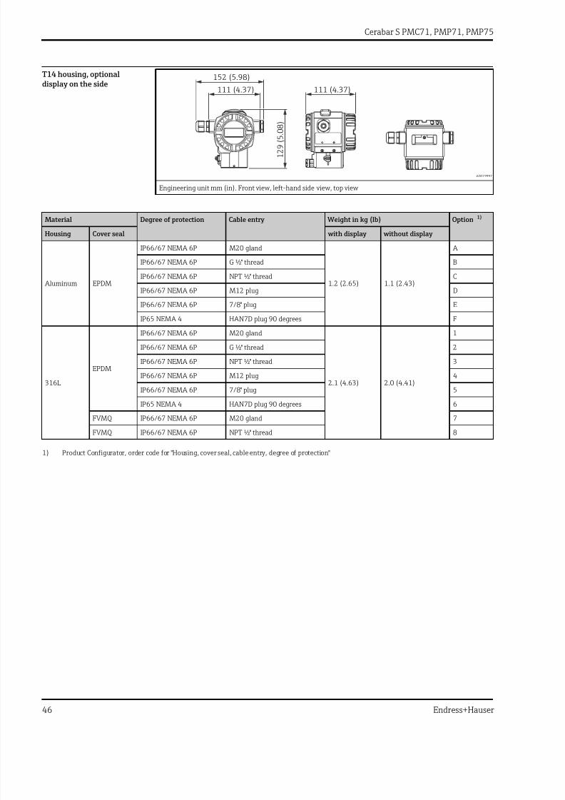
7/24/2019 Cerabar S PMC71, PMP71, PMP75
http://slidepdf.com/reader/full/cerabar-s-pmc71-pmp71-pmp75 46/116
Cerabar S PMC71, PMP71, PMP75
46 Endress+Hauser
T14 housing, optionaldisplay on the side
152 (5.98)
111 (4.37) 111 (4.37)
129
(5.08)
A0019997
Engineering unit mm (in). Front view, left-hand side view, top view
Material Degree of protection Cable entry Weight in kg (lb) Option 1)
Housing Cover seal with display without display
Aluminum EPDM
IP66/67 NEMA 6P M20 gland
1.2 (2.65) 1.1 (2.43)
A
IP66/67 NEMA 6P G ½" thread B
IP66/67 NEMA 6P NPT ½" thread C
IP66/67 NEMA 6P M12 plug D
IP66/67 NEMA 6P 7/8" plug E
IP65 NEMA 4 HAN7D plug 90 degrees F
316L
EPDM
IP66/67 NEMA 6P M20 gland
2.1 (4.63) 2.0 (4.41)
1
IP66/67 NEMA 6P G ½" thread 2
IP66/67 NEMA 6P NPT ½" thread 3
IP66/67 NEMA 6P M12 plug 4
IP66/67 NEMA 6P 7/8" plug 5
IP65 NEMA 4 HAN7D plug 90 degrees 6
FVMQ IP66/67 NEMA 6P M20 gland 7
FVMQ IP66/67 NEMA 6P NPT ½" thread 8
1) Product Configurator, order code for "Housing, cover seal, cable entry, degree of protection"

7/24/2019 Cerabar S PMC71, PMP71, PMP75
http://slidepdf.com/reader/full/cerabar-s-pmc71-pmp71-pmp75 47/116
Cerabar S PMC71, PMP71, PMP75
Endress+Hauser 47
T17 housing (hygienic),optional display on the side
94 (3.7)
132 (5.2)
115 (4.53)
147
(5.79)
A0020000
Engineering unit mm (in). Front view, left-hand side view, top view
Material Degree of protection 1) Cable entry Weight in kg (lb) Option 2)
Housing Cover seal with display without display
316L EPDM
IP66/68 NEMA 6P M20 gland
1.2 (2.65) 1.1 (2.43)
R
IP66/68 NEMA 6P G ½" thread S
IP66/68 NEMA 6P NPT ½" thread T
IP66/68 NEMA 6P M12 plug U
IP66/68 NEMA 6P 7/8" plug V
1) Degree of protection IP 68: 1.83 mH2O for 24 h
2) Product Configurator, order code for "Housing, cover seal, cable entry, degree of protection"

7/24/2019 Cerabar S PMC71, PMP71, PMP75
http://slidepdf.com/reader/full/cerabar-s-pmc71-pmp71-pmp75 48/116
Cerabar S PMC71, PMP71, PMP75
48 Endress+Hauser
Process connections forPMC71 with internal processisolating diaphragm
Threaded connection ISO 228 G
A
ø6 (0.24)
ø3 (0.12)
ø8 (0.31)
G ½" 3(0.12)
H
17(0.67)
20(0.79)
A0020935
B
ø17.5 (0.24)
G ¼"
G ½"20(0.79)
H
17(0.67)
13(0.51)
A0020936
C
ø17.5 (0.24)
ø11.4 (0.45)
G ½"
H
20(0
.79)
17(0
.67)
A0020937
Engineering unit mm (in). Height H → 50
Item Description Material Weight Approval 1) Option 2)
kg (lb)
A Thread ISO 228 G ½" A EN 837
AISI 316L
0.63 (1.39)
CRN GA
Alloy C276 (2.4819) CRN GB
Monel (2.4360) - GCPVDF• Only mount with a mounting bracket (included)• MWP 10 bar (150 psi), OPL max. 15 bar (225 psi)• Process temperature range: +10 to +60 °C (+14 to +140 °F)
- GD
BThread ISO 228 G ½" A,G ¼" (internal)
AISI 316L CRN GE
Alloy C276 (2.4819) CRN GF
Monel (2.4360) - GG
CThread ISO 228 G ½" A,bore 11.4 mm (0.45 in)
AISI 316L CRN GH
Alloy C276 (2.4819) CRN GJ
Monel (2.4360) - GK
1) CSA approval: Product Configurator, order code for "Approval"2) Product Configurator, order code for "Process connection"

7/24/2019 Cerabar S PMC71, PMP71, PMP75
http://slidepdf.com/reader/full/cerabar-s-pmc71-pmp71-pmp75 49/116
Cerabar S PMC71, PMP71, PMP75
Endress+Hauser 49
Threaded connection ANSI
A
NPT ¼"
ø11.4 (0.45)
NPT ½"
H
25(0.98)
A0020938
B
ø11.4 (0.45)
NPT ½"
H
25(0.98)
A0020939
C
ø3 (0.12)
NPT ½"
H
25(0.98)
A0020940
D
ø26.5 (1.04)
H
25(0.98)NPT ½"
A0020943
Engineering unit mm (in). Height H → 50
Item Description Material Weight Approval 1) Option 2)
kg (lb)
A ANSI ½" MNPT, ¼" FNPT
AISI 316L
0.63 (1.39)
CRN RA
Alloy C276 (2.4819) CRN RB
Monel (2.4360) - RC
B ANSI ½" MNPT,
bore 11.4 mm (0.45 in)
AISI 316L CRN RD
Alloy C276 (2.4819) CRN RE
Monel (2.4360) - RF
C ANSI ½" MNPT,
bore 3 mm (0.12 in)
PVDF• Only mount with a mounting bracket (included)• MWP 10 bar (150 psi), OPL max. 15 bar (225 psi)• Process temperature range: +10 to +60 °C (+14 to +140 °F)
- RG
D ANSI ½" FNPT
bore 11.4 mm (0.45 in)
AISI 316L CRN RH
Alloy C276 (2.4819) CRN RJ
Monel (2.4360) - RK
1) CSA approval: Product Configurator, order code for "Approval"2) Product Configurator, order code for "Process connection"

7/24/2019 Cerabar S PMC71, PMP71, PMP75
http://slidepdf.com/reader/full/cerabar-s-pmc71-pmp71-pmp75 50/116
Cerabar S PMC71, PMP71, PMP75
50 Endress+Hauser
Process connections forPMC71 with internal processisolating diaphragm
Threaded connection JIS
A
ø5 (0.2)
ø3 (0.12)
ø8 (0.31)
G ½"3(0.12)
H
20(0.79)
A0021444
B
ø11.4 (0.45)
R ½"
H
13.2(0.52)
23(0.91)
A0021445
Engineering unit mm (in). Height H → 50
Item Description Material Weight Option 1)
kg (lb)
A JIS B0202 G ½" (male) AISI 316L 0.63 (1.39)
GL
B JIS B0203 R ½" (male) RL
1) Product Configurator, order code for "Process connection"
Threaded connection DIN 13
ø6 (0.24)
ø3 (0.12)
ø8 (0.31)
M20x1.5 3(0.12)
H
17(0.67)
20(0.79)
A0020945
Engineering unit mm (in). Height H → 50
Description Material Weight Option 1)
kg (lb)
DIN 13 M20 x 1.5, EN 837
3 mm (0.12 in)
AISI 316L0.63 (1.39)
GP
Alloy C276 (2.4819) GQ
1) Product Configurator, order code for "Process connection"
Process connections forPMC71 with internal processisolating diaphragm -height H
Description Height H
Standard height 26 mm (1.02 in)
Device with Ex d[ia], CSA XP or FM XP 96 mm (3.78 in)
High-temperature version 106 mm (4.17 in)
High-temperature version with Ex d[ia], CSA XP or FM XP 176 mm (6.93 in)

7/24/2019 Cerabar S PMC71, PMP71, PMP75
http://slidepdf.com/reader/full/cerabar-s-pmc71-pmp71-pmp75 51/116
Cerabar S PMC71, PMP71, PMP75
Endress+Hauser 51
Process connections forPMC71 with flush-mountedprocess isolating diaphragm
Threaded connection DIN 13
H
60
11(0.43)
M44x1.25
22(0.87)ø40.5 (1.59)
A0020950
Engineering unit mm (in). Height H → 52
Description Material Weight Option 1)
kg (lb)
DIN 13 M44 x 1.25 AISI 316L
0.63 (1.39)1R
Alloy C276 (2.4819) 1S
1) Product Configurator, order code for "Process connection"
Threaded connection ISO 228 G
A
ø55 (2.17)
H
60
25(0.98)G 1½"
28(1.1)
A0020946
B
ø68 (2.68)
70
G 2"
H
30(1.18)
33.5(1.32)
A0020947
Engineering unit mm (in). Height H → 52
Item Description Material Weight Option 1)
kg (lb)
A Thread ISO 228 G 1 ½" A
AISI 316L
0.63 (1.39)
1G
Alloy C276 (2.4819) 1H
Monel (2.4360) 1J
B Thread ISO 228 G 2" A
AISI 316L 1K
Alloy C276 (2.4819) 1L
Monel (2.4360) 1M
1) Product Configurator, order code for "Process connection"

7/24/2019 Cerabar S PMC71, PMP71, PMP75
http://slidepdf.com/reader/full/cerabar-s-pmc71-pmp71-pmp75 52/116
Cerabar S PMC71, PMP71, PMP75
52 Endress+Hauser
Process connections forPMC71 with flush-mountedprocess isolating diaphragm
Threaded connection ANSI
A 60
NPT 1½"
H
27(1.06)
A0020948
B
ø68 (2.68)
70
H
30(1.18)
33.5(1.32)
NPT 2"
A0020949
Engineering unit mm (in). Height H → 52
Item Description Material Weight Approval 1) Option 2)
kg (lb)
A ANSI 1 ½" MNPT
AISI 316L (CRN)
0.63 (1.39)
CRN 2D
Alloy C276 (2.4819) (CRN) CRN 2E
Monel (2.4360) - 2F
B ANSI 2" MNPT
AISI 316L (CRN) CRN 2G
Alloy C276 (2.4819) (CRN) CRN 2H
Monel (2.4360) - 2J
1) CSA approval: Product Configurator, order code for "Approval"2) Product Configurator, order code for "Process connection"
Process connections forPMC71 with flush-mountedprocess isolating diaphragm- height H
Description Height H
High-temperature version 86 mm (3.39 in)
High-temperature version with Ex d[ia], CSA XP or FM XP 151 mm (5.94 in)

7/24/2019 Cerabar S PMC71, PMP71, PMP75
http://slidepdf.com/reader/full/cerabar-s-pmc71-pmp71-pmp75 53/116
Cerabar S PMC71, PMP71, PMP75
Endress+Hauser 53
Process connections forPMC71 with flush-mountedprocess isolating diaphragm
EN/DIN flanges, connection dimensions in accordance with EN 1092-1/DIN 2527
D
k
b 6 2
2
g2
g
26
A0026336
Engineering unit mm
Flange Boltholes Weight Option 1)
Material Nominal diameter Nominal pressure Shape 2) D Thickness Raised face Number g2 Hole circle
b g k
mm mm mm mm mm kg (lb)
AISI 316L DN 25 PN 10-40 B1 (D) 115 18 68 4 14 85 1.4 (3.09) BA
AISI 316L DN 32 PN 10-40 B1 (D) 140 18 78 4 18 100 2.0 (4.41) CP
AISI 316L DN 40 PN 10-40 B1 (D) 150 18 88 4 18 110 2.4 (5.29) CQ
AISI 316L DN 50 PN 10-40 B1 (D) 165 20 102 4 18 125 3.2 (7.06) B3
PVDF DN 50 PN 10-16 B1 (D) 165 21.4 102 4 18 125 0.6 (1.32) BR
AISI 316L DN 50 PN 63 (64) B2 (D) 180 26 102 4 22 135 4.6 (10.14) C3
PVDF DN 80 PN 10-16 B1 (D) 200 21.4 138 8 18 160 1.0 (2.21) BS
AISI 316L DN 80 PN 10-40 B1 (D) 200 24 138 8 18 160 5.4 (11.91) B4
1) Product Configurator, order code for "Process connection"2) Name as per DIN 2527 provided in brackets

7/24/2019 Cerabar S PMC71, PMP71, PMP75
http://slidepdf.com/reader/full/cerabar-s-pmc71-pmp71-pmp75 54/116
Cerabar S PMC71, PMP71, PMP75
54 Endress+Hauser
ASME flanges, connection dimensions in accordance with ASME B 16.5, raised face RF
D
k
b
2 . 4
4
0 . 0
8
g2
g
1.024
A0026337
Engineering unit in.
Flange Boltholes Weight Approval 1) Option 2)
Material Nominal
diameter
Class D Thickness Raised face Number g2 Hole
circle
b g k
[in] [lb./sq.in] [in] [in] [in] [in] [in] [kg (lb)]
AISI 316/316L 3) 1 150 4.25 1.18 2 4 0.62 3.12 0.9 (1.98) - AA 4)
AISI 316/316L 3) 1 300 4.88 1.18 2 4 0.75 3.5 1.4 (3.09) - AB 4)
AISI 316/316L 3) 1 ½ 150 5 0.69 2.88 4 0.62 3.88 1.0 (2.21) CRN AE
AISI 316/316L 3) 1 ½ 300 6.12 0.81 2.88 4 0.88 4.5 2.6 (5.73) CRN AQ
AISI 316/316L 3) 2 150 6 0.75 3.62 4 0.75 4.75 2.4 (5.29) CRN AF
ECTFE 5) 2 150 6 0.75 3.62 4 0.75 4.75 2.4 (5.29) - JR
PVDF 2 150 6 0.75 3.62 4 0.75 4.75 0.5 (1.1) - A3 AISI 316/316L 3) 2 300 6.5 0.88 3.62 8 0.75 5 3.2 (7.06) CRN AR
AISI 316/316L 3) 3 150 7.5 0.94 5 4 0.75 6 4.9 (10.8) CRN AG
ECTFE 5) 3 150 7.5 0.94 5 4 0.75 6 4.9 (10.8) - JS
PVDF 3 150 7.5 0.94 5 4 0.75 6 0.9 (1.98) - A4
AISI 316/316L 3) 3 300 8.25 1.12 5 8 0.88 6.62 6.8 (14.99) CRN AS
AISI 316/316L 3) 4 150 9 0.94 6.19 8 0.75 7.5 7.1 (15.66) CRN AH
ECTFE 5) 4 150 9 0.94 6.19 8 0.75 7.5 7.1 (15.66) - JT
AISI 316/316L 3) 4 300 10 1.25 6.19 8 0.88 7.88 11.6 (25.58) CRN AT
1) CSA approval: Product Configurator, order code for "Approval"2) Product Configurator, order code for "Process connection"3) Combination of AISI 316 for required pressure resistance and AISI 316L for required chemical resistance (dual rated)4) Screws must be 15 mm (0.59 in) longer than the standard flange screws5) ECTFE coating on AISI 316/316L. When operating in hazardous areas, avoid electrostatic charge on the plastic surfaces.

7/24/2019 Cerabar S PMC71, PMP71, PMP75
http://slidepdf.com/reader/full/cerabar-s-pmc71-pmp71-pmp75 55/116
Cerabar S PMC71, PMP71, PMP75
Endress+Hauser 55
JIS flanges, connection dimensions in accordance with JIS B 2220 BL, raised face RF
D
k
b 6 2
2
g2
g
26
A0026336
Engineering unit mm
Flange Boltholes Weight Option 1)
Material Nominal diameter Nominal pressure D Thickness Raised face Number g2 Hole circle
b g k mm mm mm mm mm kg (lb)
AISI 316L(1.4435)
50 A 10 K 155 16 96 4 19 120 2.0 (4.41) KF
80 A 10 K 185 18 127 8 19 150 3.3 (7.28) KL
100 A 10 K 210 18 151 8 19 175 4.4 (9.7) KH
1) Product Configurator, order code for "Process connection"
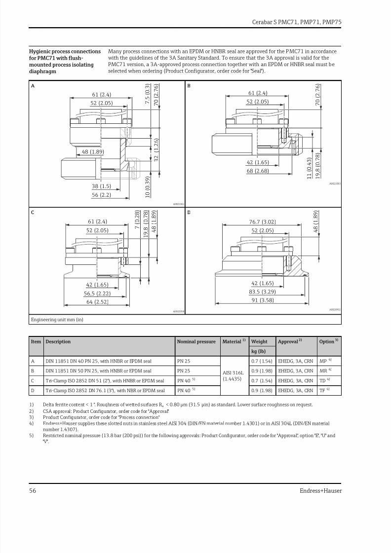
7/24/2019 Cerabar S PMC71, PMP71, PMP75
http://slidepdf.com/reader/full/cerabar-s-pmc71-pmp71-pmp75 56/116
Cerabar S PMC71, PMP71, PMP75
56 Endress+Hauser
Hygienic process connectionsfor PMC71 with flush-mounted process isolatingdiaphragm
Many process connections with an EPDM or HNBR seal are approved for the PMC71 in accordance with the guidelines of the 3A Sanitary Standard. To ensure that the 3A approval is valid for the
PMC71 version, a 3A‑approved process connection together with an EPDM or HNBR seal must beselected when ordering (Product Configurator, order code for "Seal").
A
7.5
(0.3)
10
(0.39
)
52 (2.05)
61 (2.4)
38 (1.5)
56 (2.2)
32
(1.26)
70
(2.7
6)
48 (1.89)
A0021061
B
52 (2.05)
61 (2.4)
68 (2.68)
11
(0.43)
19,8
(0.78)
70
(2.7
6)
42 (1.65)
A0021063
C
42 (1.65)
64 (2.52)
61 (2.4)
56,5 (2.22)
52 (2.05)7
(0.28)
19,8
(0.78)
48
(1.89)
A0021058
D
42 (1.65)
52 (2.05)
76.7 (3.02)
91 (3.58)
83.5 (3.29)
48
(1.89)
A0020952
Engineering unit mm (in)
Item Description Nominal pressure Material 1) Weight Approval 2) Option 3)
kg (lb)
A DIN 11851 DN 40 PN 25, with HNBR or EPDM seal PN 25
AISI 316L(1.4435)
0.7 (1.54) EHEDG, 3A, CRN MP 4)
B DIN 11851 DN 50 PN 25, with HNBR or EPDM seal PN 25 0.9 (1.98) EHEDG, 3A, CRN MR 4)
C Tri-Clamp ISO 2852 DN 51 (2"), with HNBR or EPDM seal PN 40 5) 0.7 (1.54) EHEDG, 3A, CRN TD 4)
D Tri-Clamp ISO 2852 DN 76.1 (3"), with NBR or EPDM seal PN 40 5) 0.9 (1.98) EHEDG, 3A, CRN TF 4)
1) Delta ferrite content < 1 ". Roughness of wetted surfaces R a < 0.80 µm (31.5 µin) as standard. Lower surface roughness on request.
2) CSA approval: Product Configurator, order code for "Approval"3) Product Configurator, order code for "Process connection"4) Endress+Hauser supplies these slotted nuts in stainless steel AISI 304 (DIN/EN material number 1.4301) or in AISI 304L (DIN/EN material
number 1.4307).5) Restricted nominal pressure (13.8 bar (200 psi)) for the following approvals: Product Configurator, order code for "Approval", option "E", "U" and
"V".

7/24/2019 Cerabar S PMC71, PMP71, PMP75
http://slidepdf.com/reader/full/cerabar-s-pmc71-pmp71-pmp75 57/116
Cerabar S PMC71, PMP71, PMP75
Endress+Hauser 57
E
16
(0.63)42 (1.65)
52 (2.05)
61 (2.4)
84 (3.31)
105 (4.13)
65 (2.56)
48
(1.89)
A0023740
F
42 (1.65)
75 (2.95)
71 (2.8)
84 (3.31)
52 (2.05)
12,3
(0.48)
19,8
(0.78)
48
(1.89)
A0021060
Engineering unit mm (in)
Item Description Nominal pressure Material 1) Weight Approval 2) Option 3)
kg (lb)
EDRD DN50 (65 mm)
with HNBR or EPDM sealPN 25
AISI 316L(1.4435)
0.9 (1.98) EHEDG TK 4)
F Varivent type N for pipes 40 – 162, with HNBR or EPDM seal
PN 40 1 (2.21) EHEDG, 3A, CRN TR
1) Delta ferrite content < 1 ". Roughness of wetted surfaces R a < 0.80 µm (31.5 µin) as standard. Lower surface roughness on request.2) CSA approval: Product Configurator, order code for "Approval"3) Product Configurator, order code for "Process connection"4) Endress+Hauser supplies these slotted nuts in stainless steel AISI 304 (DIN/EN material number 1.4301) or in AISI 304L (DIN/EN material
number 1.4307).

7/24/2019 Cerabar S PMC71, PMP71, PMP75
http://slidepdf.com/reader/full/cerabar-s-pmc71-pmp71-pmp75 58/116
Cerabar S PMC71, PMP71, PMP75
58 Endress+Hauser
Process connections forPMP71 with internal processisolating diaphragm
Threaded connection ISO 228 G
A
3
(0.12)
G ½ A "
ø3.2 (0.13)
ø6 (0.24)
ø17.5 (0.69)
20
(0.79)
3
(0.12)
36
(1.42)
A0021588
B
G ½ A "
G ¼"
ø17.5 (0.69) 13
(0.51)
ø11.4 (0.45) 20
(0.79)
17
(0.67)
36
(1.42)
A0021591
C
ø11.4 (0.45)
G ½ A "
ø17.5 (0.69)
20
(0
.79)
17
(0.67)
36
(1.42)
A0021592
Engineering unit mm (in)
Item Description Material Weight Option
1)
kg (lb)
A Thread ISO 228 G ½" A EN 837 AISI 316L
0.63 (1.39)
GA
Alloy C276 (2.4819) GB
BThread ISO 228 G ½" A,G ¼" (internal)
AISI 316L GE
Alloy C276 (2.4819) GF
CThread ISO 228 G ½" A,bore 11.4 mm (0.45 in)
AISI 316L GH
Alloy C276 (2.4819) GJ
1) Product Configurator, order code for "Process connection"

7/24/2019 Cerabar S PMC71, PMP71, PMP75
http://slidepdf.com/reader/full/cerabar-s-pmc71-pmp71-pmp75 59/116
Cerabar S PMC71, PMP71, PMP75
Endress+Hauser 59
Process connections forPMP71 with internal processisolating diaphragm
Threaded connection ANSI
A
15
(0.59)
ø11.4 (0.45)
ø21.4 (0.84)
25
(0.98)
NPT ½"
NPT ¼"
36
(1.42)
A0021112
B
ø21.4 (0.84)
NPT ½"
ø11.4 (0.45)
25
(0.98)
36
(1.42)
A0021113
C
ø38 (1.5)
36
(1.42)
NPT ½"
7
(0
.28)
8
(0.31)
20
(0.79)
10
(0
.39)
A0020933
Engineering unit mm (in)
Item Description Material Weight Approval 1) Option 2)
kg (lb)
A ANSI ½" MNPT, ¼" FNPT AISI 316L
0.63 (1.39)
CRN RA
Alloy C276 (2.4819) CRN RB
B ANSI ½" MNPT,
bore 11.4 mm (0.45 in) = 400 bar (6 000 psi)bore 3.2 mm (0.13 in) = 700 bar (10 500 psi)
AISI 316L CRN RD
Alloy C276 (2.4819) CRN RE
C ANSI ½" FNPT AISI 316L
0.7 (1.54)CRN RH
Alloy C276 (2.4819) CRN RJ
1) CSA approval: Product Configurator, order code for "Approval"2) Product Configurator, order code for "Process connection"

7/24/2019 Cerabar S PMC71, PMP71, PMP75
http://slidepdf.com/reader/full/cerabar-s-pmc71-pmp71-pmp75 60/116
Cerabar S PMC71, PMP71, PMP75
60 Endress+Hauser
Process connections forPMP71 with internal processisolating diaphragm
Threaded connection JIS
A
G ½"
ø3 (0.12)
ø5 (0.2)
23
(0.91)
3
(0.12)
36
(1.42)
ø8 (0.31)
A0021607
B
ø21.4 (0.84)
R ½"
ø11.4 (0.45)
23
(0.91)
36
(1.42)
A0021608
Engineering unit mm (in)
Item Description Material Weight Option
1)
kg (lb)
A JIS B0202 G ½" (male) AISI 316L 0.6 (1.32)
GL
B JIS B0203 R ½" (male) RL
1) Product Configurator, order code for "Process connection"
Threaded connection DIN 13
ø11.4 (0.45)
M20x1.5
ø17.5 (0.69)
20
(0.79)
17
(0.67)
36
(1.4
2)
A0021609
Engineering unit mm (in)
Description Material Weight Option1)
kg (lb)
DIN 13 M20 x 1.5, EN 83711.4 mm (0.45 in)
AISI 316L0.6 (1.32)
GP
Alloy C276 (2.4819) GQ
1) Product Configurator, order code for "Process connection"

7/24/2019 Cerabar S PMC71, PMP71, PMP75
http://slidepdf.com/reader/full/cerabar-s-pmc71-pmp71-pmp75 61/116
Cerabar S PMC71, PMP71, PMP75
Endress+Hauser 61
Process connections forPMP71 with flush-mountedprocess isolating diaphragm
Threaded connection ISO 228 G
A
2
(0.08)
3.5
(0.14)
14
(0.55)ø17.5 (0.69)
ø18.4 (0.72)
ø26.5 (1.04)
ø23.6 (0.93)
G ½ A "
34
(1.34)
3
(0.12)
1
A0021613
B
2
(0.08)
3.5
(0.14)
18
(0.71)
ø30 (1.18)
ø28 (1.1)
ø36 (1.42)
ø39 (1.54)
G 1" A
38
(1.5)
3
(0.12)
A0021614
C
34
(1.34)
8
(0.31)
2
(0.08)
2
6
(1.02)ø28 (1.1)
G 1½" A ø55 (2.17)
ø36 (1.42)
A0021615
D
2
(0.08)
30
(1.18)ø28 (1.1)
G 2" A
ø68 (2.68)
ø56.3 (2.22)
33
(1.3)
1
(0.04)
A0021616
Engineering unit mm (in)
Item Description Material Weight Option 1)
kg (lb)
A Thread ISO 228 G ½" A, DIN 3852FKM seal (item 1) pre-installed
AISI 316L0.4 (0.88)
1A
Alloy C276 (2.4819) 1B
B Thread ISO 228 G 1" A
AISI 316L
0.7 (1.54)
1D
Alloy C276 (2.4819) 1E
C Thread ISO 228 G 1 ½" A AISI 316L
1.1 (2.43)1G
Alloy C276 (2.4819) 1H
D Thread ISO 228 G 2" A AISI 316L
1.5 (3.31)1K
Alloy C276 (2.4819) 1L
1) Product Configurator, order code for "Process connection"

7/24/2019 Cerabar S PMC71, PMP71, PMP75
http://slidepdf.com/reader/full/cerabar-s-pmc71-pmp71-pmp75 62/116
Cerabar S PMC71, PMP71, PMP75
62 Endress+Hauser
Threaded connection DIN
A
2
(0.08)
3.5
(0.14)
14
(0.55)ø17.5 (0.69)
ø17.7 (0.7)
ø26.5 (1.04)
ø23.6 (0.93)
M20x1.5
34
(1.34)
3
(0.12)
A0021622
B
41
(1.61)
8
(0.31)
2
(0.08)
26
(0.91)ø17.5 (0.69)
M44x1.25
ø55 (2.17)
ø40 (1.57)
A0021623
Engineering unit mm (in)
Item Description Material Weight Option 1)
kg (lb)
A Thread DIN 16288 M20 AISI 316L
0.4 (0.88)1N
Alloy C276 (2.4819) 1P
B Thread DIN 13 M44 x 1.25 AISI 316L
1.1 (2.43)1R
Alloy C276 (2.4819) 1S
1) Product Configurator, order code for "Process connection"

7/24/2019 Cerabar S PMC71, PMP71, PMP75
http://slidepdf.com/reader/full/cerabar-s-pmc71-pmp71-pmp75 63/116
Cerabar S PMC71, PMP71, PMP75
Endress+Hauser 63
Process connections forPMP71 with flush-mountedprocess isolating diaphragm
Threaded connection ANSI
A
33
(1.3)
23
(0.91)
NPT 1"
ø28 (1.1)
A0021624
B
36
(1.42)
27
(1.06
)
NPT 1 "½
ø28 (1.1)
A0021625
C
30
(1.18)
31
(1.22)
NPT 2"
ø28 (1.1)
A0021626
Engineering unit mm (in)
Item Description Material Weight Approval 1) Option 2)
kg (lb)
A ANSI 1" MNPT AISI 316L
0.7 (1.54)CRN 2A
Alloy C276 (2.4819) CRN 2B
B ANSI 1 ½" MNPT AISI 316L
1 (2.21)CRN 2D
Alloy C276 (2.4819) CRN 2E
C ANSI 2" MNPT AISI 316L
1.3 (2.87)CRN 2G
Alloy C276 (2.4819) CRN 2H
1) CSA approval: Product Configurator, order code for "Approval"2) Product Configurator, order code for "Process connection"

7/24/2019 Cerabar S PMC71, PMP71, PMP75
http://slidepdf.com/reader/full/cerabar-s-pmc71-pmp71-pmp75 64/116
Cerabar S PMC71, PMP71, PMP75
64 Endress+Hauser
Process connections forPMP71 with flush-mountedprocess isolating diaphragm
EN/DIN flanges, connection dimensions in accordance with EN 1092-1/DIN 2527
D
k
b
g
60
2 d =M ø28 4
1
g2
m
A0022643
Engineering unit mm
Flange 1) Boltholes Weight
Flange
Option 2)
Nominaldiameter
Nominalpressure
Shape 3) D Thickness Raisedface
Width of Raised face
Number g2 Holecircle
b g m k
[mm] [mm] [mm] [mm] [mm] [mm] [kg]
DN 25 PN 10-40 B1 (D) 115 18 68 4) 4 4 14 85 1.2 (2.65) CN
DN 32 PN 10-40 B1 (D) 140 18 78 4) 9 4 18 100 1.9 (4.19) CP
DN 40 PN 10-40 B1 (D) 150 18 88 4) 14 4 18 110 2.2 (4.85) CQ
DN 50 PN 10-40 B1 (D) 165 20 102 - 4 18 125 3.0 (6.62) B3
DN 80 PN 10-40 B1 (D) 200 24 138 - 8 18 160 5.3 (11.69) B4
1) Material: AISI 316L2) Product Configurator, order code for "Process connection"3) Name as per DIN 2527 provided in brackets4) With these process connections the raised face is smaller than described in the standard. Due to a smaller raised face a special seal must be used.
For further information, please contact a seal manufacturer or your local Endress+Hauser Sales Center.

7/24/2019 Cerabar S PMC71, PMP71, PMP75
http://slidepdf.com/reader/full/cerabar-s-pmc71-pmp71-pmp75 65/116
Cerabar S PMC71, PMP71, PMP75
Endress+Hauser 65
Process connections forPMP71 with flush-mountedprocess isolating diaphragm
ASME flanges, connection dimensions in accordance with ASME B 16.5, raised face RF*
D
k
b
g
2.36
c d =M ø1.1 1 . 6
1
g2
m
A0022645
Engineering unit in.(*all apart from AN, see table below)
Flange 1) Boltholes Weight Approval 2) Option 3)
Nominaldiameter
Class/nominalpressure
D Thickness Raisedface
Thickness of raised face
Width of Raisedface
Number g2 Holecircle
b g c m k
[in] lb./sq.in [in] [in] [in] [in] [in] [in] [in] [kg]
1 300 4.88 0.69 2 4) 0.06 0.2 4 0.75 3.5 1.3 (2.87) CRN AN
1 ½ 150 5 0.69 2.88 4) 0.08 0.52 4 0.62 3.88 1.5 (3.31) CRN AE
1 ½ 300 6.12 0.81 2.88 4) 0.08 0.52 4 0.88 4.5 2.6 (5.73) CRN AQ
2 150 6 0.75 3.62 0.08 - 4 0.75 4.75 2.4 (5.29) CRN AF
2 300 6.5 0.88 3.62 0.08 - 8 0.75 5 3.2 (7.06) CRN AR
3 150 7.5 0.94 5 0.08 - 4 0.75 6 4.9 (10.8) CRN AG
3 300 8.25 1.12 5 0.08 - 8 0.88 6.62 6.7 (14.77) CRN AS
4 150 9 0.94 6.19 0.08 - 8 0.75 7.5 7.1 (15.66) CRN AH
4 300 10 1.25 6.19 0.08 - 8 0.88 7.88 11.6(25.88)
CRN AT
1) Material: AISI 316/316L; Combination of AISI 316 for required pressure resistance and AISI 316L for required chemical resistance (dual rated)2) CSA approval: Product Configurator, order code for "Approval"3) Product Configurator, order code for "Process connection"4) With these process connections the raised face is smaller than described in the standard. Due to a smaller raised face a special seal must be used.
For further information, please contact a seal manufacturer or your local Endress+Hauser Sales Center.

7/24/2019 Cerabar S PMC71, PMP71, PMP75
http://slidepdf.com/reader/full/cerabar-s-pmc71-pmp71-pmp75 66/116
Cerabar S PMC71, PMP71, PMP75
66 Endress+Hauser
Process connections forPMP71 with flush-mountedprocess isolating diaphragm
JIS flanges, connection dimensions in accordance with JIS B 2220 BL, raised face RF
D
k
b
g
60
2 d =M ø28 4
1
g2
m
A0022643
Engineering unit mm
Flange Boltholes Weight
Flange
Option 1)
Material Nominaldiameter
Class/Nominalpressure
D Thickness Raisedface
Width of Raised face
Number g2 Holecircle
b g m k
[mm] [mm] [mm] [mm] [mm] [mm] [kg]
AISI 316L 25 A 20 K 125 16 67 2) 3.5 4 19 90 1.5 (3.31) KA
AISI 316L 50 A 10 K 155 16 96 - 4 19 120 2.0 (4.41) KF
AISI 316L 80 A 10 K 185 18 127 - 8 19 150 3.3 (7.28) KL
AISI 316L 100 A 10 K 210 18 151 - 8 19 175 4.4 (9.7) KH
1) Product Configurator, order code for "Process connection"
2) With these process connections the raised face is smaller than described in the standard. Due to a smaller raised face a special seal must be used.For further information, please contact a seal manufacturer or your local Endress+Hauser Sales Center.

7/24/2019 Cerabar S PMC71, PMP71, PMP75
http://slidepdf.com/reader/full/cerabar-s-pmc71-pmp71-pmp75 67/116
Cerabar S PMC71, PMP71, PMP75
Endress+Hauser 67
Process connections forPMP71
Oval flange
UNF7/16-20
63.5(2.5)
78.5(3.09)
NPT¼"-18
13(0.51)
40 (1.57) 75 (2.95)
41.3(1.63)
A0021632
Engineering unit mm (in)
Material Description Weight Approval 1) Option 2)
kg (lb)
AISI 316L (1.4404)Oval flange adapter 1/4-18 NPTas per IEC 61518Mounting: 7/16-20 UNF
1.9 (4.19) CRN UR
1) CSA approval: Product Configurator, order code for "Approval"2) Product Configurator, order code for "Process connection"

7/24/2019 Cerabar S PMC71, PMP71, PMP75
http://slidepdf.com/reader/full/cerabar-s-pmc71-pmp71-pmp75 68/116
Cerabar S PMC71, PMP71, PMP75
68 Endress+Hauser
Process connections forPMP71
Prepared for diaphragm seal mount
ø7.95 (0.31)
ø2.5 (0.1)
60
(2.
36)
5
(0.2)
1 2 3
A0025596
1 Setscrew with hexagonal recess4 mm (0.16 in), material A2-702 Bearing DIN 5401 (1.3505)3 Hole for filling fluid
Engineering unit mm (in)
Material Description Weight in kg (lb) Approval 1) Option 2)
AISI 316L (1.4404) Prepared for diaphragm seal mount 1.9 (4.19) CRN U1
1) CSA approval: Product Configurator, order code for "Approval"2) Product Configurator, order code for "Process connection"
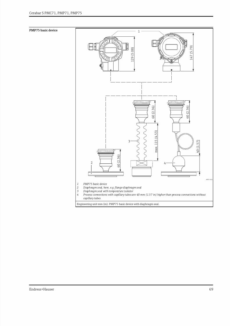
7/24/2019 Cerabar S PMC71, PMP71, PMP75
http://slidepdf.com/reader/full/cerabar-s-pmc71-pmp71-pmp75 69/116
Cerabar S PMC71, PMP71, PMP75
Endress+Hauser 69
PMP75 basic device
40(1.57)
60(2.36)
60(2.36)
60(2.3
6)
147(5.79)
129(5.08)
max.115(4.53)
1
2
3
4
A0021634
1 PMP75 basic device2 Diaphragm seal, here, e.g. flange diaphragm seal3 Diaphragm seal with temperature isolator 4 Process connections with capillary tubes are 40 mm (1.57 in) higher than process connections without
capillary tubes
Engineering unit mm (in). PMP75 basic device with diaphragm seal.
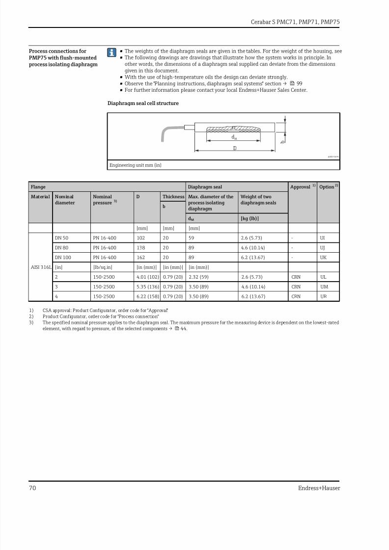
7/24/2019 Cerabar S PMC71, PMP71, PMP75
http://slidepdf.com/reader/full/cerabar-s-pmc71-pmp71-pmp75 70/116
Cerabar S PMC71, PMP71, PMP75
70 Endress+Hauser
Process connections forPMP75 with flush-mountedprocess isolating diaphragm
• The weights of the diaphragm seals are given in the tables. For the weight of the housing, see• The following drawings are drawings that illustrate how the system works in principle. In
other words, the dimensions of a diaphragm seal supplied can deviate from the dimensionsgiven in this document.
• With the use of high-temperature oils the design can deviate strongly.• Observe the "Planning instructions, diaphragm seal systems" section → 99
• For further information please contact your local Endress+Hauser Sales Center.
Diaphragm seal cell structure
dM
D
b
A0021635
Engineering unit mm (in)
Flange Diaphragm seal Approval 1) Option 2)
Material Nominaldiameter
Nominalpressure 3)
D Thickness Max. diameter of theprocess isolatingdiaphragm
Weight of twodiaphragm seals
b
dM [kg (lb)]
[mm] [mm] [mm]
AISI 316L
DN 50 PN 16-400 102 20 59 2.6 (5.73) - UI
DN 80 PN 16-400 138 20 89 4.6 (10.14) - UJ
DN 100 PN 16-400 162 20 89 6.2 (13.67) - UK
[in] [lb/sq.in] [in (mm)] [in (mm)] [in (mm)]2 150-2500 4.01 (102) 0.79 (20) 2.32 (59) 2.6 (5.73) CRN UL
3 150-2500 5.35 (136) 0.79 (20) 3.50 (89) 4.6 (10.14) CRN UM
4 150-2500 6.22 (158) 0.79 (20) 3.50 (89) 6.2 (13.67) CRN UR
1) CSA approval: Product Configurator, order code for "Approval"2) Product Configurator, order code for "Process connection"3) The specified nominal pressure applies to the diaphragm seal. The maximum pressure for the measuring device is dependent on the lowest-rated
element, with regard to pressure, of the selected components → 44.

7/24/2019 Cerabar S PMC71, PMP71, PMP75
http://slidepdf.com/reader/full/cerabar-s-pmc71-pmp71-pmp75 71/116
Cerabar S PMC71, PMP71, PMP75
Endress+Hauser 71
Process connections forPMP75 with flush-mountedprocess isolating diaphragm
Thread ISO 228 and ANSI
G
NPT
SW/AFSW/AF
dM
d1
d2
x 1
h
x 1
h
d2
dM
A0021639
Engineering unit mm (in). Left: thread ISO 228, right: thread ANSI
Threaded connection Diaphragm seal Approval 1) Option 2)
Material Thread Nominalpressure
d1 d2 Screw-inlength
Acrossflats
Max. diameter of the processisolatingdiaphragm
Height Weight
PN SW/AF h
[mm] [mm] [mm] [mm] [mm] [kg (lb)]
AISI 316L G 1" A 400 30 39 21 3) 32 30 19 0.4 (0.88) - 1D
Alloy C276 0.5 (1.1) - 1E
AISI 316L G 1 ½" A 400 44 55 30 50 42 20 0.9 (1.98) - 1G
Alloy C276 1.0 (2.21) - 1H
AISI 316L G 2" 400 56 68 30 65 50 20 1.9 (4.19) - 1K
Alloy C276 2.1 (4.63) - 1L
AISI 316L 1" MNPT 400 – 48 28 41 24 37 0.6 (1.32) CRN 2A
Alloy C276 0.7 (1.54) CRN 2B
AISI 316L 1 ½" MNPT 400 – 60 30 41 36 20 0.9 (1.98) CRN 2D
Alloy C276 1.0 (2.21) CRN 2E
AISI 316L 2" MNPT 400 – 78 30 65 38 35 1.8 (3.97) CRN 2G
Alloy C276 2.0 (4.41) CRN 2H
1) CSA approval: Product Configurator, order code for "Approval"2) Product Configurator, order code for "Process connection"3) 28 mm (1.1 in) in conjunction with high-temperature oil

7/24/2019 Cerabar S PMC71, PMP71, PMP75
http://slidepdf.com/reader/full/cerabar-s-pmc71-pmp71-pmp75 72/116
Cerabar S PMC71, PMP71, PMP75
72 Endress+Hauser
Process connections forPMP75 with flush-mountedprocess isolating diaphragm
Tri-Clamp ISO 2852
h
dM
C7
A0021644
Engineering unit mm (in)
Material 1) NominaldiameterISO 2852
NominaldiameterDIN 32676
Nominaldiameter
Diameter Max. diameter of theprocess isolatingdiaphragm
Height Weight Approval 2) Option 3)
Standard With TempCdiaphragm
C7 dM dM h[in] [mm] [mm] [mm] [mm] [kg (lb)]
AISI 316L
ND 25 / 33.7 DN 25 1 50.5 24 - 37 0.32(0.71)
EHEDG, 3A,CRN
TB
ND 38 DN 40 1 ½ 50.5 36 36 30 1 (2.21) EHEDG, 3A,CRN
TC 4) 5)
ND 51 / 40 DN 50 2 64 48 41 30 1.1 (2.43) EHEDG, 3A,CRN
TD 4) 5)
ND 63.5 DN 50 2 ½ 77.5 61 61 30 0.7 (1.54) EHEDG, 3A TE 6)
ND 76.1 – 3 91 73 61 30 1.2 (2.65) EHEDG, 3A,CRN
TF 5)
1) Surface roughness of the wetted surfaces R a < 0.76 µm (29.9 µin) as standard. Lower surface roughness on request.
2) CSA approval: Product Configurator, order code for "Approval".3) Product Configurator, order code for "Process connection"4) Diaphragm seal version optionally in conformity with ASME BPE for use in biochemical processes, wetted surfaces R a < 0.38 µm (15 µin)),
electropolished; to be ordered using feature "Additional options", version "P" in the order code.5) Alternatively available with TempC diaphragm.6) With TempC diaphragm
Max. PN = 40 bar (580 psi). The maximum PN depends on the clamp used.

7/24/2019 Cerabar S PMC71, PMP71, PMP75
http://slidepdf.com/reader/full/cerabar-s-pmc71-pmp71-pmp75 73/116
Cerabar S PMC71, PMP71, PMP75
Endress+Hauser 73
Process connections forPMP75 with flush-mountedprocess isolating diaphragm
Tri-Clamp pipe diaphragm seal ISO 2852
d 2
h
L
D
A0021671
Engineering unit mm (in)
Material 1) Nominal diameterISO 2852
Nominaldiameter
Nominalpressure
D d2 Height Installationlength
Weight Approval 2) Option 3)
h L
[in] [in] [mm] [mm] [mm] [kg (lb)]
AISI 316L
DN 25 1 PN 40 22.5 50.5 67 126 1.7 (3.75) 3A, CRN SB
DN 38 1 ½ PN 40 35.5 50.5 67 126 1.0 (2.21) 3A, CRN SC 4)
DN 51 2 PN 40 48.6 64 79 100 1.7 (3.75) 3A, CRN SD 4)
1) Surface roughness of the wetted surfaces R a < 0.8 µm (31.5 µin) as standard.
2) CSA approval: Product Configurator, order code for "Approval"3) Product Configurator, order code for "Process connection"
4) incl. 3.1 and pressure test in accordance with the Pressure Equipment Directive, category II

7/24/2019 Cerabar S PMC71, PMP71, PMP75
http://slidepdf.com/reader/full/cerabar-s-pmc71-pmp71-pmp75 74/116
Cerabar S PMC71, PMP71, PMP75
74 Endress+Hauser
Hygienic process connectionsfor PMP75 with flush-mounted process isolatingdiaphragm
Varivent for pipes
30
(1.18)
D
dM
A0021672
Engineering unit mm (in)
Material 1) Description Nominalpressure
D Max. diameter of the process isolatingdiaphragm
Weight Approval Option 2)
Standard With TempC
diaphragmdM dM
[mm] [mm] [mm] [kg (lb)]
AISI 316L Type F for pipes DN 25 - DN32
PN 40 50 34 36 0.4 (0.88) EHEDG, 3A TU 3)
AISI 316L Type N for pipes DN 40 - DN162
PN 40 68 58 61 0.8 (1.76) EHEDG, 3A TR 4) 5)
1) Surface roughness of the wetted surfaces R a < 0.76 µm (29.9 µin) as standard.
2) Product Configurator, order code for "Process connection"3) With TempC diaphragm4) Diaphragm seal version optionally in conformity with ASME BPE for use in biochemical processes, wetted surfaces R a < 0.38 µm (15 µin)),
electropolished; to be ordered using feature "Additional options", version "P" in the order code. Lower surface roughness on request.5) Alternatively available with TempC diaphragm.

7/24/2019 Cerabar S PMC71, PMP71, PMP75
http://slidepdf.com/reader/full/cerabar-s-pmc71-pmp71-pmp75 75/116
Cerabar S PMC71, PMP71, PMP75
Endress+Hauser 75
Hygienic process connectionsfor PMP75 with flush-mounted process isolatingdiaphragm
DRD DN50 (65 mm)
ø65 (2.56 )-1.2 -0.05
ø84 (3.31)
ø105 (4.13)23.6
(0.93)
41
(1.61)
4 x
ø11.5 (0.45)
dM
A0021673
Engineering unit mm (in)
Material 1) Nominal pressure Max. diameter of the process isolating diaphragm Weight Option 2)
Standard With TempC diaphragm
dM dM
[mm] [mm] [kg (lb)]
AISI 316L PN 25 50 48 0.75 (1.65) TK 3)
1) Surface roughness of the wetted surfaces R a < 0.76 µm (29.9 µin) as standard.
2) Product Configurator, order code for "Process connection"3) Alternatively available with TempC diaphragm.
SMS nozzles with coupling nut
f h
G
D
m
dM
A0021674
Engineering unit mm (in)
Material1)
Nominaldiameter
Nominalpressure
D Nozzleheight
Thread Height Height Max.diameterof thediaphragm
Weight Approval Option 2)
f G m h dM
[mm] [mm] [mm] [mm] [mm] [kg (lb)]
AISI 316L
1 PN 25 54 3.5 Rd 40 – 1/6 20 42.5 24 0.25 (0.55) 3A, EHEDG TG
1 ½ PN 25 74 4 Rd 60 – 1/6 25 57 36 0.65 (1.43) 3A, EHEDG TH 3)
2 PN 25 84 4 Rd 70 – 1/6 26 62 48 1.05 (2.32) 3A, EHEDG TI 3)
1) Surface roughness of the wetted surfaces R a < 0.76 µm (29.9 µin) as standard.
2) Product Configurator, order code for "Process connection"3) Alternatively available with TempC diaphragm.

7/24/2019 Cerabar S PMC71, PMP71, PMP75
http://slidepdf.com/reader/full/cerabar-s-pmc71-pmp71-pmp75 76/116
Cerabar S PMC71, PMP71, PMP75
76 Endress+Hauser
APV-RJT nozzles with coupling nut
f h
G
D
m
dM
A0021674
Engineering unit mm (in)
Material 1) Nominaldiameter
Nominalpressure
D Nozzleheight
Thread Height Height Max. diameter of the processisolatingdiaphragm
Weight Option 2)
PN f G m h dM
[in] [bar] [mm] [mm] [mm] [mm] [mm] [kg (lb)]
AISI 316L
1 PN 40 77 6.5 1 13/16 – 1/8" 22 42.6 21 0.45 (0.99) TL
1 ½ PN 40 72 6.4 2 5/16 – 1/8" 22 42.6 28 0.75 (1.65) TM
2 PN 40 86 6.4 2 7/8 – 1/8" 22 42.6 38 1.2 (2.65) TN
1) Surface roughness of the wetted surfaces R a < 0.8 µm (31.5 µin) as standard.
2) Product Configurator, order code for "Process connection"
APV-ISS nozzles with coupling nut
G
D
dM
4
(0.16)
50
(1.97)
30
(1.18)
SW/AF
A0021677
Engineering unit mm (in)
Material 1) Nominal diameter Nominal pressure D Thread Across flats Max. diameter of the processisolating diaphragm
Weight Option 2)
PN G AF dM
[in] [bar] [mm] [mm] [kg (lb)]
AISI 316L
1 PN 40 54.1 1 ½" – 1/8" 46.8 24 0.4 (0.88) TP
1 ½ PN 40 72 2" – 1/8" 62 34 0.6 (1.32) TQ
2 PN 40 89 2 ½" – 1/8" 77 45 1.1 (2.43) TS
1) Surface roughness of the wetted surfaces R a < 0.8 µm (31.5 µin) as standard.2) Product Configurator, order code for "Process connection"

7/24/2019 Cerabar S PMC71, PMP71, PMP75
http://slidepdf.com/reader/full/cerabar-s-pmc71-pmp71-pmp75 77/116
Cerabar S PMC71, PMP71, PMP75
Endress+Hauser 77
Hygienic process connectionsfor PMP75 with flush-mounted process isolatingdiaphragm
Taper adapter with coupling nut, DIN 11851
40(1.57)
D
G
dM
f
m
A0021678
Engineering unit mm (in)
Material 1) Taper adapter Slotted nut Diaphragm seal Approval Option 2)
Max. diameter of theprocess isolatingdiaphragm
Weight
Description Nominalpressure
D Nozzleheight
Thread Height Standard With TempCdiaphragm
PN f G m dM dM
[bar] [mm] [mm] [mm] [mm] [mm] [kg (lb)]
AISI 316L
DN 32 PN 40 50 10 Rd 58 x 1/6" 21 32 28 0.45(0.99)
3A, EHEDG MI 3)
DN 40 PN 40 56 10 Rd 65 x 1/6" 21 38 36 0.45(0.99)
3A, EHEDG MZ 3)
DN 50 PN 25 68.5 11 Rd 78 x 1/6" 19 52 48 1.1 (2.43) 3A, EHEDG MR 4)
DN 65 PN 25 86 12 Rd 95 x 1/6" 21 66 61 2.0 (4.41) 3A, EHEDG MS 4)
DN 80 PN 25 100 12 Rd 110 x1/4"
26 81 61 2.55(5.62)
3A, EHEDG MT 4)
1) Surface roughness of the wetted surfaces R a < 0.76 µm (29.9 µin) as standard.2) Product Configurator, order code for "Process connection"3) With TempC diaphragm4) Alternatively available with TempC diaphragm.

7/24/2019 Cerabar S PMC71, PMP71, PMP75
http://slidepdf.com/reader/full/cerabar-s-pmc71-pmp71-pmp75 78/116
Cerabar S PMC71, PMP71, PMP75
78 Endress+Hauser
NEUMO BioControl
Process temperature range: –10 to +200 °C (+14 to +392 °F)
D
d dM
d2
d3
d1
h
A0023435
Engineering unit mm (in)
Material 1) NEUMO BioControl Diaphragm seal Approv-al
Option 2)
Max. diameter of the process
isolating diaphragm
Weight
Nominalof thediaphragm
Nominalpressure
Diameter Holecircle
Height Standard With TempCdiaphragm
PN D d2 d3 d1 m dM dM
[bar] [mm] [mm] [mm] [mm] [mm] [mm] [mm] [kg (lb)]
AISI 316LDN 50 PN 16 90 4 x Ø 9 50 70 27 40 36 1.1 (2.43) 3A S4 3)
DN 80 PN 16 140 4 x Ø 11 87.4 115 37 61 61 2.6 (5.73) 3A S6 3)
1) Surface roughness of the wetted surfaces R a < 0.76 µm (29.9 µin) as standard.2) Product Configurator, order code for "Process connection"3) With TempC diaphragm
Universal process adapter
ø43.5 (1.71)
= ø36 (1.42)
68.5
(2.7)
1
2
dM
3
A0020013
Engineering unit mm (in)
Description Material 1) Weight Approval Option 2)
[kg (lb)]
Universal process adapter with pre-installed silicone molded seal(item 3) (spare part no.: 52023572) FDA 21CFR177.2600/USPClass VI-70C
• Item 1: Top section AISI 316L (1.4404)• Item 2: Bottom section AISI 316L (1.4435)
0.8 (1.76) 3A, EHEDG 00 3) 4)
1) Surface roughness of the wetted surfaces R a < 0.76 µm (29.9 µin) as standard. Surface quality R a< 0.38 µm (15 µin) electropolished (wetted),
ordering information: Product Configurator, order code for "Additional options 2", version "P".2) Product Configurator, order code for "Process connection"
3) Endress+Hauser supplies these slotted nuts in stainless steel AISI 304 (DIN/EN material number 1.4301) or in AISI 304L (DIN/EN materialnumber 1.4307).4) Alternatively available with TempC diaphragm.

7/24/2019 Cerabar S PMC71, PMP71, PMP75
http://slidepdf.com/reader/full/cerabar-s-pmc71-pmp71-pmp75 79/116
Cerabar S PMC71, PMP71, PMP75
Endress+Hauser 79
Process connections forPMP75 with flush-mountedprocess isolating diaphragm
EN/DIN flanges, connection dimensions in accordance with EN 1092-1/DIN 2527 and DIN2501-1
g2
dM
k
D
g
b
4 0
f
A0021680
Engineering unit mm
Flange 1) 2) 3) Boltholes Diaphragm seal Option 4)
Nominaldiameter
Nominalpressure
Shape 5) D Thickness Raised face Number g2 Holecircle
Max.diameterprocessisolatingdiaphragm
Weight
b g f k
[mm] [mm] [mm] [mm] [mm] [mm] dM [kg (lb)]
DN 25 PN 10-40 B1 (D) 115 18 68 3 4 14 85 32 2.1 (4.63) CN
DN 25 PN 63-160 B2 (E) 140 24 68 2 4 18 100 28 2.5 (5.51) DN
DN 25 PN 250 B2 (E) 150 28 68 2 4 22 105 28 3.7 (8.16) EN
DN 25 PN 400 B2 (E) 180 38 68 2 4 26 130 28 7.0 (15.44) E1
DN 32 PN 10-40 B1 (D) 140 18 77 2.6 4 18 100 34 1.9 (4.19) CP
DN 40 PN 10-40 B1 (D) 150 18 87 2.6 4 18 110 48 2.2 (4.85) CQ
DN 50 PN 10-40 B1 (D) 165 20 102 3 4 18 125 59 3.0 (6.62) B3
DN 50 PN 63 B2 (E) 180 26 102 3 4 22 135 59 4.6 (10.14) C3
DN 50 PN 100-160 B2 (E) 195 30 102 3 4 26 145 59 6.2 (13.67) EF
DN 50 PN 250 B2 (E) 200 38 102 3 8 26 150 59 7.7 (16.98) ER
DN 50 PN 400 B2 (E) 235 52 102 3 8 30 180 59 14.7 (32.41) E3
DN 80 PN 10-40 B1 (D) 200 24 138 3.5 8 18 160 89 5.3 (11.69) B4
DN 80 PN 100 B2 (E) 230 32 138 4 8 24 180 89 8.9 (19.62) C4
DN 100 PN 100 B2 (E) 265 36 175 5 8 30 210 89 13.7 (30.21) C5
1) Material: AISI 316L2) The surface roughness of the wetted surfaces, including the raised face of flanges (all standards) made of Alloy C276, Monel, tantalum, rhodium-
gold or PTFE is R a< 0.8 µm (31.5 µin). Lower surface roughness on request.
3) The flange raised face is made of the same material as the process isolating diaphragm.4) Product Configurator, order code for "Process connection"5) Name as per DIN 2527 provided in brackets

7/24/2019 Cerabar S PMC71, PMP71, PMP75
http://slidepdf.com/reader/full/cerabar-s-pmc71-pmp71-pmp75 80/116
Cerabar S PMC71, PMP71, PMP75
80 Endress+Hauser
EN/DIN flanges with barrel (extended diaphragm seal), connection dimensions in accordance with EN 1092-1/DIN 2527 and DIN 2501-1
g2
dM
d3
k
D
g
b
4 0
3
A0023914
Engineering unit mm
Flange 1) 2) Boltholes Diaphragm seal Option 3)
Nominaldiameter
Nominalpressure
Shape 4) D Thickness Raisedface
Number g2 Holecircle
Max.diameter of theprocess isolatingdiaphragm
Weight
b g k
[mm] [mm] [mm] [mm] [mm] dM [kg (lb)]
DN 50 PN 10-40 B1 (D) 165 20 102 4 18 125 47 5) D3 5)
DN 80 PN 10-40 B1 (D) 200 24 138 8 18 160 72 5) D4 5)
1) Material: AISI 316L2) For process isolating diaphragms made of Alloy C276, Monel oder tantalum, the raised face of the flange and the barrel pipe are made of 316L3) Product Configurator, order code for "Process connection"4) Name as per DIN 2527 provided in brackets5) Available with 50 mm (1.97 in), 100 mm (3.94 in) and 200 mm (7.87 in) barrel, (extended diaphragm seal), for barrel (extended diaphragm
seal) diameter and weight see the following table
Option 1) Nominal diameter Nominal pressure Barrel (extended diaphragmseal) length
Barrel (extendeddiaphragm seal)diameter
Weight
(L) d3
[mm] [mm] [kg (lb)]
D3 DN 50 PN 10-40 50 / 100 / 200 48.3 3.2 (7.1)/ 3.8 (8.4)/ 4.4 (9.7)
D4 DN 80 PN 10-40 50 /100 / 200 76 6.2 (13.7)/ 6.7 (14.8)/ 7.8(17.2)
1) Product Configurator, order code for "Process connection"

7/24/2019 Cerabar S PMC71, PMP71, PMP75
http://slidepdf.com/reader/full/cerabar-s-pmc71-pmp71-pmp75 81/116
Cerabar S PMC71, PMP71, PMP75
Endress+Hauser 81
Process connections forPMP75 with flush-mountedprocess isolating diaphragm
ASME flanges, in accordance with connection dimensions ASME B 16.5, raised face RF
g2
dM
k
D
g
b
1 . 5
7
f
A0023913
Engineering unit in
Flange 1) 2) 3) Boltholes Diaphragm seal Approval 4) Option 5)
Nominaldiameter Class D Thickness Raised face Number g2 Holecircle Max.diameter of theprocess isolatingdiaphragm
Weight
b g f k dM
[in] [lb./sq.in] [in] [in] [in] [in] [in] [in] [in] [kg (lb)]
1 150 4.25 0.56 2 0.08 4 0.62 3.12 1.26 1.2 (2.65) CRN AC
1 300 4.88 0.69 2 0.08 4 0.75 3.5 1.26 1.3 (2.87) CRN AN
1 400/600 4.88 0.69 2 0.25 4 0.75 3.5 1.26 1.4 (3.09) CRN HC
1 900/1500 5.88 1.12 2 0.25 4 1 4 1.26 3.2 (7.06) CRN HN
1 2500 6.25 1.38 2 0.25 4 1 4.25 1.26 4.6 (10.14) CRN HO
1 ½ 150 5 0.69 2.88 0.06 4 0.62 3.88 1.89 1.5 (3.31) CRN AE
1 ½ 300 6.12 0.81 2.88 0.06 4 0.88 4.5 1.89 2.6 (5.73) CRN AQ
2 150 6 0.75 3.62 0.06 4 0.75 4.75 2.32 2.2 (4.85) CRN AF
2 300 6.5 0.88 3.62 0.06 8 0.75 5 2.32 3.4 (7.5) CRN AR
2 400/600 6.5 1 3.62 0.25 8 0.75 5 2.32 4.3 (9.48) CRN HF
2 900/1500 8.5 1.5 3.62 0.25 8 1 6.5 2.32 10.3 (22.71) CRN HR
2 2500 9.25 2 3.62 0.25 8 1.12 6.75 2.32 15.8 (34.84) - H3
3 150 7.5 0.94 5 0.06 4 0.75 6 3.5 5.1 (11.25) CRN AG
3 300 8.25 1.12 5 0.06 8 0.75 6 3.5 7.0 (15.44) CRN AS
4 150 9 0.94 6.19 0.06 8 0.75 7.5 3.5 7.2 (15.88) CRN AH
4 300 10 1.25 6.19 0.06 8 0.88 7.88 3.5 11.7 (25.8) CRN AT
1) Material AISI 316/316L: Combination of AISI 316 for required pressure resistance and AISI 316L for required chemical resistance (dual rated)2) The surface roughness of the wetted surfaces, including the raised face of flanges (all standards) made of Alloy C276, Monel, tantalum, rhodium-
gold or PTFE, is R a< 0.8 µm (31.5 µin). Lower surface roughness on request.
3) The flange raised face is made of the same material as the process isolating diaphragm.4) CSA approval: Product Configurator, order code for "Approval"5) Product Configurator, order code for "Process connection"
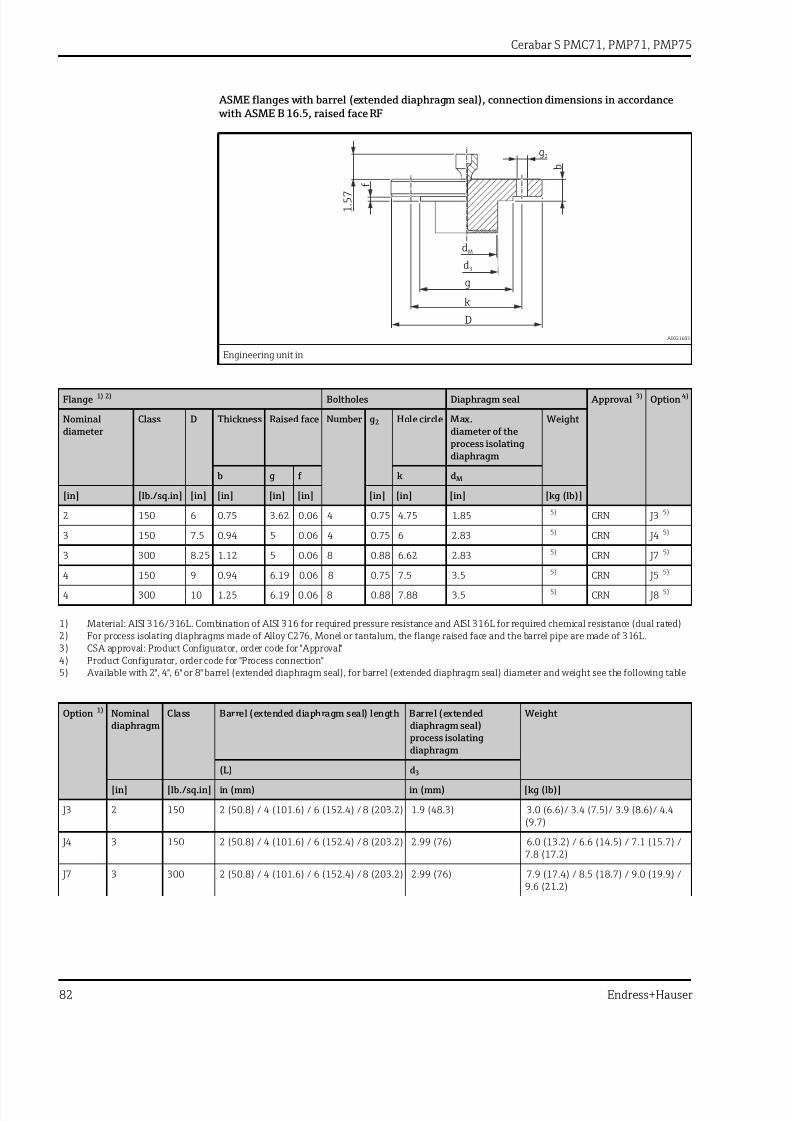
7/24/2019 Cerabar S PMC71, PMP71, PMP75
http://slidepdf.com/reader/full/cerabar-s-pmc71-pmp71-pmp75 82/116
Cerabar S PMC71, PMP71, PMP75
82 Endress+Hauser
ASME flanges with barrel (extended diaphragm seal), connection dimensions in accordance with ASME B 16.5, raised face RF
g2
dM
d3
k
D
g
b
1 . 5
7
f
A0021683
Engineering unit in
Flange 1) 2) Boltholes Diaphragm seal Approval 3) Option 4)
Nominaldiameter
Class D Thickness Raised face Number g2 Hole circle Max.diameter of theprocess isolatingdiaphragm
Weight
b g f k dM
[in] [lb./sq.in] [in] [in] [in] [in] [in] [in] [in] [kg (lb)]
2 150 6 0.75 3.62 0.06 4 0.75 4.75 1.85 5) CRN J3 5)
3 150 7.5 0.94 5 0.06 4 0.75 6 2.83 5) CRN J4 5)
3 300 8.25 1.12 5 0.06 8 0.88 6.62 2.83 5) CRN J7 5)
4 150 9 0.94 6.19 0.06 8 0.75 7.5 3.5 5) CRN J5 5)
4 300 10 1.25 6.19 0.06 8 0.88 7.88 3.5 5) CRN J8 5)
1) Material: AISI 316/316L. Combination of AISI 316 for required pressure resistance and AISI 316L for required chemical resistance (dual rated)2) For process isolating diaphragms made of Alloy C276, Monel or tantalum, the flange raised face and the barrel pipe are made of 316L.3) CSA approval: Product Configurator, order code for "Approval"4) Product Configurator, order code for "Process connection"5) Available with 2", 4", 6" or 8" barrel (extended diaphragm seal), for barrel (extended diaphragm seal) diameter and weight see the following table
Option 1) Nominal
diaphragm
Class Barrel (extended diaphragm seal) length Barrel (extended
diaphragm seal)process isolatingdiaphragm
Weight
(L) d3
[in] [lb./sq.in] in (mm) in (mm) [kg (lb)]
J3 2 150 2 (50.8) / 4 (101.6) / 6 (152.4) / 8 (203.2) 1.9 (48.3) 3.0 (6.6)/ 3.4 (7.5)/ 3.9 (8.6)/ 4.4(9.7)
J4 3 150 2 (50.8) / 4 (101.6) / 6 (152.4) / 8 (203.2) 2.99 (76) 6.0 (13.2) / 6.6 (14.5) / 7.1 (15.7) /7.8 (17.2)
J7 3 300 2 (50.8) / 4 (101.6) / 6 (152.4) / 8 (203.2) 2.99 (76) 7.9 (17.4) / 8.5 (18.7) / 9.0 (19.9) /9.6 (21.2)

7/24/2019 Cerabar S PMC71, PMP71, PMP75
http://slidepdf.com/reader/full/cerabar-s-pmc71-pmp71-pmp75 83/116
Cerabar S PMC71, PMP71, PMP75
Endress+Hauser 83
Option 1) Nominaldiaphragm
Class Barrel (extended diaphragm seal) length Barrel (extendeddiaphragm seal)process isolatingdiaphragm
Weight
(L) d3
[in] [lb./sq.in] in (mm) in (mm) [kg (lb)] J5 4 150 2 (50.8) / 4 (101.6) / 6 (152.4) / 8 (203.2) 3.7 (94) 8.6 (19) / 9.9 (21.8) / 11.2 (24.7) /
12.4 (27.3)
J8 4 300 2 (50.8) / 4 (101.6) / 6 (152.4) / 8 (203.2) 3.7 (94) 13.1 (28.9)/ 14.4 (31.6)/ 15.7 (34.6)/16.9 (37.3)
1) Product Configurator, order code for "Process connection"

7/24/2019 Cerabar S PMC71, PMP71, PMP75
http://slidepdf.com/reader/full/cerabar-s-pmc71-pmp71-pmp75 84/116
Cerabar S PMC71, PMP71, PMP75
84 Endress+Hauser
JIS flanges, connection dimensions in accordance with JIS B 2220 BL, raised face RF
g2
dM
k
D
g
b
4 0
f
A0021680
Engineering unit mm
Flange 1) 2) 3) Boltholes Diaphragm seal Option 4)
Nominal
diameter
Nominal
pressure
D Thickness Raised face Number g2 Hole circle Max.
diameter of theprocess isolatingdiaphragm
Weight
b g f k dM
[mm] [mm] [mm] [mm] [mm] [mm] [mm] [kg (lb)]
25 A 10 K 125 14 67 1 4 19 90 32 1.5 (3.31) KC
50 A 10 K 155 16 96 2 4 19 120 59 2.3 (5.07) KF
80 A 10 K 185 18 127 2 8 19 150 89 3.3 (7.28) KL
100 A 10 K 210 18 151 2 8 19 175 89 4.4 (9.7) KH
1) Material: AISI 316L2) The surface roughness of the wetted surfaces, including the raised face of flanges (all standards) made of Alloy C276, Monel, tantalum, rhodium-
gold or PTFE is R a< 0.8 µm (31.5 µin). Lower surface roughness on request.
3) The flange raised face is made of the same material as the process isolating diaphragm.4) Product Configurator, order code for "Process connection"

7/24/2019 Cerabar S PMC71, PMP71, PMP75
http://slidepdf.com/reader/full/cerabar-s-pmc71-pmp71-pmp75 85/116
Cerabar S PMC71, PMP71, PMP75
Endress+Hauser 85
Process connections forPMP75 with flush-mountedprocess isolating diaphragm
Thread ½ NPT and 1 NPT, separator
76
(2.99)
94.5
(3.72)
26
(1.02)
ø118 (4.65)
ø30 (1.18)
ø52 (2.05)
ø118 (4.65)
19
(0.75)
12
(0.47)NPT ½"
NPT 1"
27
36
44
(1.75)
27
(1.06)
15
(0.59)
A0021684
Engineering unit mm (in)
Material Description Measuring range Nominal pressure Weight Option 1)
[bar (psi)] [kg (lb)]
AISI 316LThreaded, ½" NPT with Viton seal (200 °C (392 °F)
≤ 250 (3625) PN 2504.75 (10.47) UG
Threaded, 1" NPT with Viton seal 5.0 (11.03) UH
1) Product Configurator, order code for "Process connection"
Thread ISO 228 G ½ A and ANSI ½ MNPT, separator
ø6 (0.24)
ø4 (0.16)
G ½"A
NPT ½" 14
14
(0.55)
70
(2.76)
70
(2.76)
20
(0.79)
17
(0.67)
3
(0.12)
ø18.4 (0.72)
ø72.6 (2.86) ø72.6 (2.86)
14
(0.55)
21.5
(0.85)
ø min 4 (0.16)
A0021685
Engineering unit mm (in)
Material Description Measuring range Nominal pressure Approval Weight Option 1)
[bar (psi)] [kg (lb)]
AISI 316L Welded, ISO 228 G ½ A EN837
≤ 160 (2320) PN 160-
1.43 (3.15)UA
Welded, ANSI ½ MNPT CRN 2) UB
1) Product Configurator, order code for "Process connection"2) CSA approval: Product Configurator, order code for "Approval"

7/24/2019 Cerabar S PMC71, PMP71, PMP75
http://slidepdf.com/reader/full/cerabar-s-pmc71-pmp71-pmp75 86/116
Cerabar S PMC71, PMP71, PMP75
86 Endress+Hauser
max.
89(3.5)
max.
89(3.5)
100 3.94
22
1
A B
1
22
100 3.94
NPT ½"
G ½"
ø6 (0.24)
A0027135
A Option "UC" with threaded connection ISO 228 G ½ B B Option "UD" with threaded connection ANSI ½ MNPT 1 PTFE seal as standard max. 260 °C (500 °F) (higher temperatures on request)
Engineering unit mm (in)
Material Description Measuring range Nominal pressure Weight Option 1)
[bar (psi)] [kg (lb)]
AISI 316L (1.4404),screws made of A2
ISO 228 G ½ B EN837≤ 40 (580) PN 40 1.43 (3.15)
UC
ANSI ½ MNPT UD
1) Product Configurator, order code for "Process connection"
ø115 (4.53)
NPT ½"
84
(3.31)
19
(0.75)
36
ø2.5 (0.1)
100
(3.94)
20
(0.79)
17
(0.67)
3
(0.12)
ø115 (4.53)
G ½"
ø2.5 (0.1)
22
A0021688
Engineering unit mm (in)
Material Description Measuring range Nominal pressure Weight Option 1)
[bar (psi)] [kg (lb)]
AISI 316L (1.4404),screws made of A2
Threaded, ISO 228 G ½ B EN837, with integrated seal lip> 40 bar (580) PN 400 4.75 (10.47)
UC
Threaded, ANSI ½ MNPT, with integrated seal lip UD
1) Product Configurator, order code for "Process connection"

7/24/2019 Cerabar S PMC71, PMP71, PMP75
http://slidepdf.com/reader/full/cerabar-s-pmc71-pmp71-pmp75 87/116
Cerabar S PMC71, PMP71, PMP75
Endress+Hauser 87
Separate housing: Wall andpipe mounting withmounting bracket
122 (4.8)
52
(2.05)
86
(3.39)
70
(2.76)
84 (3.31)
129
(5.08)
147
(5.79)
140 (5.51)
158 (6.22) 175 (6.89)
A
B 76 (2.99)
ø52 (2.05) ø20 (0.79)
6
(0.24)
ø 6 (
0 . 2
4 )
ø42...60 (1.65...2.36)
A0020017
Engineering unit mm (in)
Position Description Weight in kg (lb) Option 1)
Housing (T14 or T17) Mounting bracket
A Dimensions with T14 housing,optional side display
→ 46
0.5 (1.10) UB Dimensions with T17 housing,
optional side display
1) Product Configurator, order code for "Additional options 2", version "G"
Also available for order as a separate accessory: Part number 71102216

7/24/2019 Cerabar S PMC71, PMP71, PMP75
http://slidepdf.com/reader/full/cerabar-s-pmc71-pmp71-pmp75 88/116
Cerabar S PMC71, PMP71, PMP75
88 Endress+Hauser
Materials not in contact withprocess
Transmitter housing
T14
1
2
3
3
2
4
12
13
5
6
15
16
18
9
8
7
1011
14
16
17
A0020019
Item number Component part Material
1 T14 housing, RAL 5012 (blue)• Die-cast aluminum with protective powder-
coating on polyester base• Thread coating: Heat-curing lubricant varnish
1 T14 housing• Precision casting AISI 316L (1.4435)• Thread coating: Heat-curing lubricant varnish
2 Cover, RAL 7035 (gray) Die-cast aluminum with protective powder-coatingon polyester base
3 Cover seal EPDM
4 Nameplates AISI 316L (1.4404)
5 Pressure compensation filter AISI 316L (1.4404) and PBT-FR
6 Pressure compensation filter, O-ring
VMQ or EPDM
7 Sight glass Mineral glass
8 Sight glass seal Silicone (VMQ)
9 Screw A4
10 Sealing ring EPDM
11 Snap ring PA66-GF25
12 Snap ring for nameplates AISI 304 (1.4301)/AISI 316 (1.4401)
13 External ground terminal AISI 304 (1.4301)
14 Cover clamp Clamp AISI 316L (1.4435), screw A4
15 Cable entry Polyamide (PA) or CuZn nickel-plated
16 Seal of cable entry and plug Silicone (VMQ)
17 Blind plug PBT-GF30 FR, for dust ignition-proof: AISI 316L(1.4435)
18 External operation (keys and key cover), RAL 7035 (gray)
Polycarbonate PC-FR, screw A4
Devices with MIDparts certificate
Seal wire DIN 1367-0 St/Zn (soft galvanized steel)
Devices with MIDparts certificate
Seals Pb (lead)

7/24/2019 Cerabar S PMC71, PMP71, PMP75
http://slidepdf.com/reader/full/cerabar-s-pmc71-pmp71-pmp75 89/116
Cerabar S PMC71, PMP71, PMP75
Endress+Hauser 89
T17 1
2
3
7
8
9
13
14
3
26
5
15
16 16
17
4
101112
A0020021
Item number Component part Material
1 T17 housing AISI 316L (1.4404)
2 Cover3 Cover seal EPDM
4 Nameplates Lasered on
5 Pressure compensation filter AISI 316L (1.4404) and PBT-FR
6 Pressure compensation filter, O-ring VMQ or EPDM
7 Sight glass for non-hazardous area, ATEX Exia, NEPSI Zone 0/1 Ex ia, IECEx Zone 0/1 Ex ia,FM NI, FM IS, CSA IS
Polycarbonate (PC)
8 Sight glass for ATEX 1/2 D, ATEX 1/3 D, ATEX 1 GD, ATEX 1/2 GD, ATEX 3 G, FM DIP,
CSA dust ignition-proof
Mineral glass
9 Sight glass seal EPDM
10 Screw A2-70
11 Sealing ring EPDM
12 Snap ring PA6
13 Screw A4-50Thread coating: Heat-curing lubricant
varnish
14 External ground terminal AISI 304 (1.4301)
15 Cable entry Polyamide PA, for dust ignition-proof:CuZn nickel-plated
16 Seal of cable entry and plug Silicone (VMQ)17 Blind plug PBT-GF30 FR, for dust ignition-proof:
AISI 316L (1.4435)
Devices with MIDparts certificate
Seal wire DIN 1367-0 St/Zn (soft galvanizedsteel)
Devices with MIDparts certificate
Seals Pb (lead)

7/24/2019 Cerabar S PMC71, PMP71, PMP75
http://slidepdf.com/reader/full/cerabar-s-pmc71-pmp71-pmp75 90/116
Cerabar S PMC71, PMP71, PMP75
90 Endress+Hauser
Connecting parts
1 1
2 3 4 4
6591
5
6
7
8
10
11
A0020022
Item number Component part Material
1 Connection between the housing andprocess connection
AISI 316L (1.4404)
2 Mounting bracket Bracket AISI 316L (1.4404)
3 Screw and nuts A4-70
4 Half-shells: AISI 316L (1.4404)
5 Seal for cable from separate housing EPDM
6 Gland for cable from separate housing AISI 316L (1.4404)
7 PE cable for separate housing abrasion-proof cable with strain-relief Dynemamembers; shielded using aluminum-coated foil;insulated with polyethylene (PE-LD), black; copper
wires, twisted, UV‑resistant
8 FEP cable for separate housing Abrasion-proof cable; shielded using galvanized steel wire netting; insulated with fluorinated ethylene
propylene (FEP), black; copper cores, twisted, UV-resistant
9 Process connection adapter forseparate housing AISI 316L (1.4404)
10 Capillary AISI 316 Ti (1.4571)
11 Flexible armor for capillary AISI 316L (1.4404)
Materials in contact withprocess
NOTICE
‣ Process-wetted device components are listed in the "Mechanical construction" → 45 and "Ordering information" → 109sections.
TSE Certificate of Suitability (Transmissible Spongiform Encephalopathy)
The following applies to all device components in contact with the process:
• They do not contain any materials derived from animals.• No additives or operating materials derived from animals are used in production or processing.

7/24/2019 Cerabar S PMC71, PMP71, PMP75
http://slidepdf.com/reader/full/cerabar-s-pmc71-pmp71-pmp75 91/116
Cerabar S PMC71, PMP71, PMP75
Endress+Hauser 91
Process connections
• "Clamp connections" and "Hygienic process connections": AISI 316L (DIN/EN material number1.4435)
• Endress+Hauser supplies process connections with threaded connections and DIN/ EN flangesmade of stainless steel as per AISI 316L (DIN/EN material number 1.4404 (AISI 316) or 1.4435).
With regard to their stability-temperature property, the materials 1.4404 and 1.4435 are grouped
together under 13E0 in EN 1092-1: 2001 Tab. 18. The chemical composition of the two materialscan be identical.
• Some process connections are also available in alloy C276 (DIN/EN material number 2.4819). Forthis purpose see the information in the "Mechanical construction" section.
Process isolating diaphragm
Sensor Description Option 1)
PMC71 Al2O3 Aluminum oxide ceramic FDA, ultrapure 99.9 % 2)
Ceraphire® (see also www.endress.com/ceraphire)Standard
PMP71
AISI 316L 1
AISI 316L with gold-rhodium coating 6
Alloy C276 (2.4819) 2
PMP75
AISI 316L 1
AISI 316L, TempC E
AISI 316L with gold-rhodium coating 6
AISI 316L with 0.25 mm (0.01 in)PTFE coating (FDA 21 CFR 177.1550) 8
Alloy C276 (2.4819) 2 3)
Monel (2.4360) 3 3)
Tantalum (UNS R05200) 5 3)
1) Product Configurator, order code for "Material of the process isolating diaphragm"2) The US Food & Drug Administration (FDA) has no objection to the use of ceramics made of aluminumoxide as a surface material in contact with foods. This declaration is based on the FDA certificates of ourceramic suppliers
3) The material of the flange raised face is the same material as is used for the process isolating diaphragm.For devices with an extended diaphragm seal, the flange raised face and the barrel (extended diaphragmseal) pipe are made of 316L.
Seals
Device Description Option 1)
PMC71
FKM Viton A
FKM Viton, FDA G
EPDM B
Kalrez D
Chemraz E
NBR (FDA)/3A: HNBR (FDA) F
FKM Viton, cleaned for silicone-free applications L
Kalrez, cleaned for silicone-free applications M
FKM Viton, cleaned from oil and grease 1
FKM Viton, cleaned for oxygen service, note pressure and temperature application limits 2
1) Product Configurator, order code for "Seal"

7/24/2019 Cerabar S PMC71, PMP71, PMP75
http://slidepdf.com/reader/full/cerabar-s-pmc71-pmp71-pmp75 92/116
Cerabar S PMC71, PMP71, PMP75
92 Endress+Hauser
Fill fluid PMP71
Description Option 1)
Silicone oil A
Inert oil F
Inert oil, cleaned from oil and grease K
Inert oil, cleaned for oxygen service (observe application limits pressure/temperature) N
1) Product Configurator, order code for "Fill fluid"
PMP75
Description Option 1)
Silicone oil A
...m capillary, inert oil B
...ft capillary, inert oil C
Vegetable oil D
Inert oil F
High-temperature oil, temperature isolator G
Silicon oil, temperature isolator H
Inert oil, cleaned from oil and grease K
Inert oil, cleaned for oxygen service N
...m capillary, silicone oil 1
...ft capillary, silicone oil 2
...m capillary, high-temperature oil 3
...ft capillary, high-temperature oil 4
...m capillary, vegetable oil 5
...ft capillary, vegetable oil 6
...m capillary, low-temperature oil 7
...ft capillary, low-temperature oil 8
1) Product Configurator, order code for "Fill fluid"

7/24/2019 Cerabar S PMC71, PMP71, PMP75
http://slidepdf.com/reader/full/cerabar-s-pmc71-pmp71-pmp75 93/116
Cerabar S PMC71, PMP71, PMP75
Endress+Hauser 93
Operability
Operating concept Operator-oriented menu structure for user-specific tasks
• Commissioning• Operation
• Diagnosis
Fast and safe commissioning
Guided menus for applications
Reliable operation
• Local operation possible in several languages• Standardized operation at the device and in the operating tools• Parameters relating to measured values can be locked/unlocked using the device's write protection
switch, using the device software or via remote operation
Efficient diagnostics increase measurement availability
• Remedial measures are integrated in plain text• Diverse simulation options
Local operation Functions
Function External operation(operating keys,optional, not T17
housing)
Internal operation(electronic insert)
Onsite display (optional)
Position adjustment (zero point correction)
Setting lower-range value and upper-range value - reference pressure present at the
device
(HART only)
(HART only)
Device reset
Locking and unlocking parameters relevant tothe measured value
¾
Value acceptance indicated by green LED
Switching damping on and off (only if display is
connected)
(HART and PA only)
Configuring the bus address of the device(PA)
¾
Switching simulation mode on and off(FOUNDATION Fieldbus)
¾
Operating the device using onsite display (optional)
A 4-line liquid crystal display (LCD) is used for display and operation. The onsite display showsmeasured values, dialog text as well as fault and notice messages in plain text, thereby supportingthe user in every stage of operation.
The display can be removed for easy operation.
The device display can be turned in 90° steps.
Depending on the installation position of the device, this makes it easy to operate the device andread the measured value.

7/24/2019 Cerabar S PMC71, PMP71, PMP75
http://slidepdf.com/reader/full/cerabar-s-pmc71-pmp71-pmp75 94/116
Cerabar S PMC71, PMP71, PMP75
94 Endress+Hauser
Functions:• 8-digit measured value display incl. leading sign and decimal point, bar graph for
– 4 to 20 mA HART as current display – PROFIBUS PA as graphic display of the standardized value of the AI block – FOUNDATION Fieldbus as graphic display of the transducer output.
• Simple and complete menu guidance due to breakdown of parameters into several levels and
groups• Menu guidance in up to 8 languages• Each parameter is given a 3-digit ID number for easy navigation.• Option for configuring the display according to individual requirements and preferences, such as
language, alternating display, display of other measured values such as sensor temperature,contrast setting.
• Comprehensive diagnostic functions (fault and warning message, peak-hold indicators, etc.).• Rapid and safe commissioning with the Quick Setup menus.
Overview
1
3
2
4
E+ –
A0016498
1 Operating keys2 Bargraph3 Symbol4 Header 5 Parameter ID number
Operating keys on the exterior of the device
With the aluminum housing (T14), the operating keys are located either outside on the housing,under the protection cap or inside on the electronic insert. With the stainless steel housing (T17),the operating keys are always located inside the housing on the electronic insert.
0%
Zero
A
B
A0020030
A 4 to 20 mA HART B PROFIBUS PA and FOUNDATION Fieldbus
The operating keys located externally on the device work on the Hall sensor principle. As a result, no
additional openings are required in the device. This guarantees:• Complete protection against environmental influences such as moisture and contamination.• Simple operation without any tools.• No wear.

7/24/2019 Cerabar S PMC71, PMP71, PMP75
http://slidepdf.com/reader/full/cerabar-s-pmc71-pmp71-pmp75 95/116
Cerabar S PMC71, PMP71, PMP75
Endress+Hauser 95
Ordering information:
Product Configurator, order code for "Output, operation"
Operating keys and elements located internally on the electronic insert
Ordering information:
Product Configurator, order code for "Output, operation"
HART
21 P
C
3 4 5 61 2
on
off
A0020031
1 DIP switch for locking/unlocking parameters relevant to the measured value2 DIP switch for switching damping on/off 3 Green LED to indicate value being accepted4 Operating keys5 Slot for optional display6 Slot for optional HistoROM®/M-DAT
PROFIBUS PA
Address
SW
HW
1 2 3 4 5 6 7 8
21
CKON
3 4 5 6 7 8
S D A 0 8
21 P C
3 4 5 6 7
on
off
1 2
0%
Zero
A0020032
1 DIP switch for locking/unlocking parameters relevant to the measured value2 DIP switch for switching damping on/off 3 Green LED to indicate value being accepted4 Key for position adjustment and device reset 5 DIP switch for bus address6 Slot for optional display7 Slot for optional HistoROM®/M-DAT

7/24/2019 Cerabar S PMC71, PMP71, PMP75
http://slidepdf.com/reader/full/cerabar-s-pmc71-pmp71-pmp75 96/116
Cerabar S PMC71, PMP71, PMP75
96 Endress+Hauser
FOUNDATION Fieldbus
HW
21 P C
3 4 5 6
on
off
1 2
0%
Zero
S i m
.
S i m u
l a t i o n
A0020033
1 DIP switch for locking/unlocking parameters relevant to the measured value2 DIP switch for simulation mode on/off 3 Green LED to indicate value being accepted4 Key for position adjustment and device reset 5 Slot for optional display6 Slot for optional HistoROM®/M-DAT
Remote operation All software parameters are accessible depending on the position of the write protection switch onthe device.
Hardware and software for remote operation HART PROFIBUS PA FOUNDATION Fieldbus
FieldCare
FieldXpert SFX100 ¾
NI-FBUS Configurator ¾ ¾
HistoROM®/M-DAT
FieldCare
FieldCare is an Endress+Hauser asset management tool based on FDT technology. With FieldCare, you can configure all Endress+Hauser devices as well as devices from other manufacturers that
support the FDT standard.
FieldCare supports the following functions:• Configuration of transmitters in offline and online mode• Loading and saving device data (upload/download)• HistoROM®/M-DAT analysis• Documentation of the measuring point
Connection options:• HART via Commubox FXA195 and the USB port on a computer• PROFIBUS PA via segment coupler and PROFIBUS interface card• Service interface with Commubox FXA291 and ToF adapter FXA291 (USB).
For further information please contact your local Endress+Hauser Sales Center.
Field Xpert SFX100
Field Xpert is an industrial PDA with integrated 3.5" touchscreen from Endress+Hauser based on Windows Mobile. It offers wireless communication via the optional VIATOR Bluetooth modem from
Endress+Hauser. Field Xpert also works as a stand-alone device for asset management applications.For details, refer to BA00060S/04/EN.
Commubox FXA195
For intrinsically safe HART communication with FieldCare via the USB interface. For details refer toTI00404F/00/EN.

7/24/2019 Cerabar S PMC71, PMP71, PMP75
http://slidepdf.com/reader/full/cerabar-s-pmc71-pmp71-pmp75 97/116
Cerabar S PMC71, PMP71, PMP75
Endress+Hauser 97
Commubox FXA291
The Commubox FXA291 connects Endress+Hauser field devices with a CDI interface (=Endress+Hauser Common Data Interface) to the USB interface of a personal computer or a notebook. Fordetails refer to TI00405C/07/EN.
For the following Endress+Hauser devices you need the "ToF adapter FXA291" as an additional
accessory:• Cerabar S PMC71, PMP7x• Deltabar S PMD7x, FMD7x• Deltapilot S FMB70
ToF adapter FXA291
The ToF adapter FXA291 connects the Commubox FXA291 with devices of the ToF platform,pressure equipment and Gammapilot via the USB interface of a personal computer or a notebook.For details refer to KA00271F.
Profiboard
For connecting a PC to PROFIBUS.
ProficardFor connecting a laptop to PROFIBUS
FF configuration program
FF configuration program, such as NI-FBUS Configurator, to• connect devices with "FOUNDATION Fieldbus signal" into an FF network • set FF-specific parameters
Remote operation via the NI-FBUS Configurator:
The NI-FBUS Configurator is an easy-to-use graphical environment for creating linkages, field-basedcontrol loops and schedules based on the FOUNDATION Fieldbus concept.
You can use the NI-FBUS Configurator to configure a fieldbus network as follows:
• Set block and device tags• Set device addresses• Create and edit function block control strategies (function block applications)• Configure vendor-defined function and transducer blocks• Create and edit schedules• Read and write to function block control strategies (function block applications)• Invoke Device Description (DD) methods• Display DD menus• Download a configuration• Verify a configuration and compare it to a saved configuration• Monitor a downloaded configuration• Replace a virtual device by a real device• Save and print a configuration
HistoROM®/M-DAT(optional)
HistoROM®/M-DAT is a memory module which can be attached to every electronic insert.HistoROM®/M-DAT can be retrofitted at any stage (order number: 52027785).
The benefits for you• Quick and safe commissioning of the same measuring points by copying the configuration data of
one transmitter to another transmitter.• Reliable process monitoring thanks to cyclical recording of pressure and sensor temperature
measured values.• Simple diagnosis by recording diverse events such as alarms, configuration changes, counters for
measuring range undershoot and overshoot for pressure and temperature as well as user limitovershoot and undershoot for pressure and temperature etc.
• Analysis and graphic evaluation of the events and process parameters via software (contained inscope of supply).
A CD with an Endress+Hauser operating program is also included in the scope of delivery. You cancopy data from one transmitter to another transmitter when operating a FOUNDATION Fieldbusdevice via an FF configuration program. You need the Endress+Hauser FieldCare operating programand the Commubox FXA291 service interface and the ToF adapter FXA291 to be able to access thedata and events saved in the HistoROM®/M-DAT.

7/24/2019 Cerabar S PMC71, PMP71, PMP75
http://slidepdf.com/reader/full/cerabar-s-pmc71-pmp71-pmp75 98/116
Cerabar S PMC71, PMP71, PMP75
98 Endress+Hauser
Ordering information:
Product Configurator, order code for "Additional options:", version "N" or
Product Configurator, order code for "Application package:", option "EN" or
as a separate accessory (part no.: 52027785).
For further information please contact your local Endress+Hauser Sales Center.
System integration The device can be given a tag name (max. 8 alphanumeric characters).
Description Option 1)
Measuring point (TAG), see additional spec. Z1
Bus address, see additional spec. Z2
1) Product Configurator, order code for "Marking"

7/24/2019 Cerabar S PMC71, PMP71, PMP75
http://slidepdf.com/reader/full/cerabar-s-pmc71-pmp71-pmp75 99/116
Cerabar S PMC71, PMP71, PMP75
Endress+Hauser 99
Planning instructions, diaphragm seal systemsNOTICE
Incorrect sizing/ordering of diaphragm seal systemsThe performance and the permitted range of application of a diaphragm seal system depend on theprocess isolating diaphragm used, the filling oil, the coupling, the unit design and on the process and
ambient conditions present in the individual application.‣ To help you select the right diaphragm seal system for your applications, Endress+Hauser
provides its customers with the free "Applicator Sizing Diaphragm Seal" tool, which is available onDVD or at "www.endress.com/applicator".
2
3
1
A0021695-EN
1 My Applicator - configuration of the Applicator settings2 Applicator help3 Mouse-over help - hover the cursor over these fields for brief information
For more detailed information or the layout of the optimum diaphragm seal solution for yourapplication, please contact your local Endress+Hauser Sales Center.
Applications Diaphragm seal systems should be used if the process and the device should be separated.Diaphragm seal systems offer clear advantages in the following instances:
• In the case of extreme process temperatures• For aggressive media• In the case of process media that crystallize• In the case of corrosive or highly various process media or process media with solids content• In the case of heterogeneous and fibrous process media• If extreme measuring point cleaning is necessary, or for very humid mounting locations• If the measuring point is exposed to severe vibrations• For mounting locations that are difficult to access

7/24/2019 Cerabar S PMC71, PMP71, PMP75
http://slidepdf.com/reader/full/cerabar-s-pmc71-pmp71-pmp75 100/116
Cerabar S PMC71, PMP71, PMP75
100 Endress+Hauser
Design and operation mode Diaphragm seals are separating equipment between the measuring system and the process.
A diaphragm seal system consists of:• A diaphragm seal• If necessary, a capillary tube or temperature isolator• Fill fluid
• A pressure transmitterThe process pressure acts via the process isolating diaphragm of a diaphragm seal on the liquid-filledsystem, which transfers the process pressure onto the sensor of the pressure transmitter.
Endress+Hauser delivers all diaphragm seal systems as welded versions. The system is hermetically sealed, which ensures the highest reliability.
The diaphragm seal determines the application range of the system by:• The process isolating diaphragm diameter• The process isolating diaphragm stiffness and material• The design (oil volume)
diameter of the process isolating diaphragm
The greater the diameter of the process isolating diaphragm (less stiff), the smaller the temperature
effect on the measurement result.
Stiffness of the process isolating diaphragm
The stiffness depends on the diameter of the process isolating diaphragm, the material, any existingcoating and the thickness and shape of the process isolating diaphragm. The process isolatingdiaphragm thickness and the shape are determined by the design. The stiffness of a process isolatingdiaphragm of a diaphragm seal influences the temperature operating range and the measuring errorcaused by temperature effects.
The new TempC diaphragm: Highest accuracy and process safety in pressure and differential pressuremeasurement with diaphragm seals
To measure even more precisely in such applications and to increase process safety, Endress+Hauserhas developed the TempC diaphragm based on a completely revolutionary technology. This
diaphragm guarantees the highest level of accuracy and process safety in diaphragm sealapplications.• The very low temperature effect minimizes the influence of fluctuations of both process and
ambient temperatures, thus guaranteeing accurate and stable measurements. Measurementinaccuracies caused by temperature are reduced to a minimum.
• The TempC diaphragm can be used at temperatures between –40 °C (–40 °F) and+250 °C (+482 °F). This guarantees maximum process safety even for very long sterilization andcleaning cycles (SIP/CIP) in tanks and pipes at high temperatures.
• Thanks to the TempC diaphragm, smaller dimension process connections are possible. With asmaller process connection, the new diaphragm measures at least as accurately as a conventionaldiaphragm with a larger diameter.
• Short recovery times after temperature shocks mean less downtime during batch processes andtherefore a far higher level of availability of the production facilities.
• In addition, the TempC diaphragm excels in terms of its improved hygienic cleanability and its
insensitivity to substantial changes in the pressure load.Ordering information:
See the Product Configurator for the individual process connection and the choice of processisolating diaphragm.
Selection in the Applicator:
Under "Transmitter data" in the "Diaphragm material" field.
Capillary
As standard, capillaries with an internal diameter of 1 mm (0.04 in) are used.
The capillary tube influences the thermal change, the ambient temperature operating range and theresponse time of a diaphragm seal system as a result of its length and internal diameter.

7/24/2019 Cerabar S PMC71, PMP71, PMP75
http://slidepdf.com/reader/full/cerabar-s-pmc71-pmp71-pmp75 101/116
Cerabar S PMC71, PMP71, PMP75
Endress+Hauser 101
Filling oil
When selecting the filling oil, the media and ambient temperature as well as the operating pressureare of crucial importance. Observe the temperatures and pressures during commissioning andcleaning. A further selection criterion is the compatibility of the filling oil with the requirements ofthe process media. For this reason, only filling oils that are harmless to health may be used in thefood industry, such as vegetable oil or silicone oil (see also the following section on "diaphragm seal
filling oils").
The filling oil used influences the thermal change, the temperature operating range of a diaphragmseal system and the response time. A temperature change results in a volume change of the fillingoil. The volume change is dependent on the expansion coefficient and on the volume of the filling oilat calibration temperature (constant in range: +21 to +33 °C (+70 to +91 °F)). The application rangecan be extended by a filling oil with a lower expansion coefficient and a shorter capillary.
For example, the filling oil expands in the event of a temperature increase. The additional volumepresses against the process isolating diaphragm of a diaphragm seal. The stiffer a diaphragm is, thegreater its return force, which counteracts a volume change and acts on the measuring cell together
with the operating pressure, thus shifting the zero point.
Pressure transmitter
The pressure transmitter influences the temperature operating range, the TK zero point and theresponse time as a result of its volume change. The volume change is the volume that has to beshifted to pass through the complete measuring range.
Pressure transmitters from Endress+Hauser are optimized with regard to minimum volume change.
Diaphragm seal filling oils
Filling oil Permittedtemperature range 1)
at0.05 bar (0.725 psi)≤ pabs ≤1 bar (14.5 psi)
Permitted temperaturerange 1) atpabs
≥1 bar (14.5 psi)
Density [g/cm3] /[SGU]
Viscosity [mm²/s] / [cSt]at25 °C (77 °F)
Expansioncoefficient 2)
[1/K]
Notes Option 3)
Silicone oil –40 to +180 °C(–40 to +356 °F)
–40 to +250 °C(–40 to +752 °F)
0.96 100 0.00096 (Suitable for use infood FDA 21 CFR 175.105)
A, H, 1 or 2
High-temperature oil
–10 to +200 °C(+14 to +392 °F)
–10 to +400 °C(+14 to +752 °F) 4) 5) 6)
1.00 150 0.00096 (Hightemperatures)
G, 3 or 4
Inert oil –40 to +80 °C(–40 to +176 °F)
–40 to +175 °C(–40 to +347 °F)
1.87 27 0.000876 (For ultrapure gasand oxygenapplications)
F or N
Vegetable oil –10 to +120 °C(+14 to +248 °F)
–10 to +200 °C(+14 to +392 °F)
0.94 9.5 0.00101 (Suitable for use infood FDA 21 CFR 172.856)
D, 5 or 6
Low-
temperature oil
–70 to +80 °C
(–94 to +176 °F)
–70 to +180 °C
(–94 to +356 °F)
0.92 4.4 0.00108 (Low
temperatures)
7 or 8
1) Observe temperature limits of the device and the system.2) For the thermal change of the diaphragm seal as well as other important technical performance characteristics, please refer to the
"Applicator Sizing Diaphragm Seal" selection tool.3) Product Configurator, order code for "Fill fluid"4) 325 °C (617 °F) at 1 bar (14.5 psi) absolute pressure.5) 350 °C (662 °F) at 1 bar (14.5 psi) absolute pressure (max. 200 hours).6) 400 °C (752 °F) at 1 bar (14.5 psi) absolute pressure (max. 10 hours).

7/24/2019 Cerabar S PMC71, PMP71, PMP75
http://slidepdf.com/reader/full/cerabar-s-pmc71-pmp71-pmp75 102/116
Cerabar S PMC71, PMP71, PMP75
102 Endress+Hauser
Information on cleaning • Endress+Hauser provides flushing rings as an accessory to enable cleaning of the process isolatingdiaphragm without removing the transmitter from the process. For further information pleasecontact your local Endress+Hauser Sales Center.
• We recommend you perform CIP (cleaning in place (hot water)) before SIP (sterilization in place(steam)) for pipe diaphragm seals. A frequent use of sterilization in place (SIP) will increase thestress on the process isolating diaphragm. Under unfavorable circumstances in the long term view
we cannot exclude that a frequent temperature change could lead to a material fatigue of theprocess isolating diaphragm and possibly to a leakage.
Installation instructions Diaphragm seal systems
• The diaphragm seal together with the transmitter form a closed, calibrated system, which is filledthrough ports in the diaphragm seal and in the measuring system of the transmitter. These portsare sealed and must not be opened.
• For devices with a temperature isolator or capillary, a suitable fastening device (mounting bracket)is recommended.
• For more detailed installation instructions, Endress+Hauser provides its customers with the free "Applicator Sizing Diaphragm Seal" tool, which is available on CD or can be downloaded online at "www.endress.com/applicator".
Capillary
In order to obtain more precise measurement results and to avoid a defect in the device, mount thecapillaries as follows:• vibration-free (in order to avoid additional pressure fluctuations)• not in the vicinity of heating or cooling lines• insulate if the ambient temperature is below or above the reference temperature• with a bending radius ≥ 100 mm (3.94 in)• Sufficient strain relief must be ensured for diaphragm seal systems with capillaries in order to
prevent the capillaries from buckling (bending radius ≥ 100 mm (3.94 in)).• In the case of devices with diaphragm seals and capillaries, the zero point shift caused by the
hydrostatic pressure of the filling liquid column in the capillaries must be taken into account whenselecting the measuring cell. If a measuring cell with a small measuring range is selected, aposition adjustment can cause range violation.
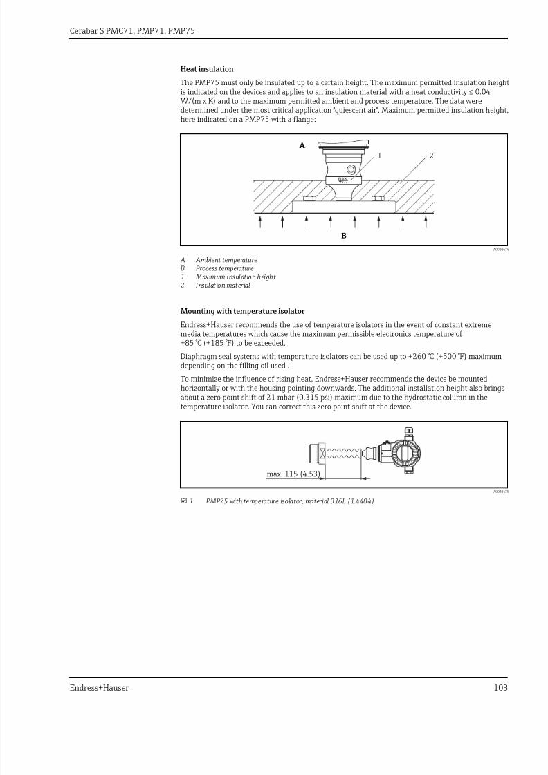
7/24/2019 Cerabar S PMC71, PMP71, PMP75
http://slidepdf.com/reader/full/cerabar-s-pmc71-pmp71-pmp75 103/116
Cerabar S PMC71, PMP71, PMP75
Endress+Hauser 103
Heat insulation
The PMP75 must only be insulated up to a certain height. The maximum permitted insulation heightis indicated on the devices and applies to an insulation material with a heat conductivity ≤ 0.04
W/(m x K) and to the maximum permitted ambient and process temperature. The data weredetermined under the most critical application "quiescent air". Maximum permitted insulation height,here indicated on a PMP75 with a flange:
A
B
1 2
A0020474
A Ambient temperature B Process temperature1 Maximum insulation height 2 Insulation material
Mounting with temperature isolator
Endress+Hauser recommends the use of temperature isolators in the event of constant extrememedia temperatures which cause the maximum permissible electronics temperature of+85 °C (+185 °F) to be exceeded.
Diaphragm seal systems with temperature isolators can be used up to +260 °C (+500 °F) maximumdepending on the filling oil used .
To minimize the influence of rising heat, Endress+Hauser recommends the device be mountedhorizontally or with the housing pointing downwards. The additional installation height also bringsabout a zero point shift of 21 mbar (0.315 psi) maximum due to the hydrostatic column in thetemperature isolator. You can correct this zero point shift at the device.
max. 115 (4.53)
A0020475
1 PMP75 with temperature isolator, material 316L (1.4404)

7/24/2019 Cerabar S PMC71, PMP71, PMP75
http://slidepdf.com/reader/full/cerabar-s-pmc71-pmp71-pmp75 104/116
Cerabar S PMC71, PMP71, PMP75
104 Endress+Hauser
Vacuum applications Installation instructions
For applications under vacuum, Endress+Hauser recommends mounting the pressure transmitterbelow the diaphragm seal. This prevents vacuum loading of the diaphragm seal caused by thepresence of fill fluid in the capillary.
When the pressure transmitter is mounted above the diaphragm seal, the maximum height
difference H1 in accordance with the illustration below must not be exceeded. The following graphicdepicts mounting above the lower diaphragm seal:
H1
F I E L D T E R M I N A L S
A0020472
The maximum height difference depends on the density of the filling oil and the smallest everpressure that is permitted to occur at the diaphragm seal (empty container), see the followingdiagram. The following diagram depicts the maximum installation height above the diaphragm sealfor vacuum applications.
1
2
3
4
5
A
B
0.0
6.6
13
20
26
33
39
1 1.45 4.35 6 7.25 9 10.15 12 13.05 14.53 [psiabs]
[ft]
A0023986-EN
A Height difference H1 B Pressure at diaphragm seal1 Low-temperature oil2 Vegetable oil3 Silicone oil4 High-temperature oil5 Inert oil

7/24/2019 Cerabar S PMC71, PMP71, PMP75
http://slidepdf.com/reader/full/cerabar-s-pmc71-pmp71-pmp75 105/116
Cerabar S PMC71, PMP71, PMP75
Endress+Hauser 105
Certificates and approvals
CE mark The device meets the legal requirements of the relevant EC directives. Endress+Hauser confirms thatthe device has been successfully tested by applying the CE mark.
C-tick mark The measuring system complies with EMC requirements of the "Australian Communications andMedia Authority (ACMA)".
Ex approvals • ATEX• FM• CSA • NEPSI• IECEx• TIIS• GOST• Also combinations of different approvals
All explosion protection data are given in separate documentation which is available upon request.The Ex documentation is supplied as standard with all devices approved for use in explosion
hazardous areas → 112.
Suitable for hygieneapplications
All materials in contact with foodstuffs comply with framework regulation (EC) 1935/2004. Thedevice is available with hygienic process connections (overview: see order code).
LCAUTION
Contamination in the process!Risk of contamination if incorrect seals and parts are used!‣ To avoid the risk of contamination, when installing the device comply with the design principles
of EHEDG, Guideline 37 "Hygienic Design and Application of Sensors" and Guideline 16 "HygienicPipe Couplings".
‣ Suitable assemblies and seals must be used to ensure hygienic design in accordance with 3-A SSIand EHEDG specifications.
‣ The leak-proof connections can be cleaned with the cleaning methods typical of this industry (CIP and SIP). Attention must be paid to the pressure and temperature specifications of thesensor and process connections for CIP and SIP processes (clean in place/sterilize in place).
TYPE ELOctober 2007
74 -
A0026782
The gap-free connections can be cleaned of all residue using the usual cleaning methods withinthis industry.
Functional safety SIL/IEC 61508 Declaration of Conformity (optional)
The Cerabar S devices with a 4 to 20 mA output signal have been developed in accordance with theIEC 61508 standard. These devices can be used to monitor the process level and pressure up to SIL 3.For a detailed description of the safety functions with Cerabar S, settings and functional safety data,see the "Functional safety manual - Cerabar S" SD00190P/00.
For devices up to SIL 3 / IEC 61508 Declarations of Conformity see:
Ordering information:Product Configurator, order code for "Additional options 1" and "Additional options 2", version "E".
Overfill protection WHG (see document ZE00260P/00/DE)

7/24/2019 Cerabar S PMC71, PMP71, PMP75
http://slidepdf.com/reader/full/cerabar-s-pmc71-pmp71-pmp75 106/116
Cerabar S PMC71, PMP71, PMP75
106 Endress+Hauser
Ordering information:
Product Configurator, order code for "Approval", option "6".
CRN approval Some device versions have CRN approval. A CRN-approved process connection with a CSA approvalmust be ordered for a CRN-approved device. These devices are fitted with a separate plate bearing
the registration number CRN 0F10525.5C .PMP75 devices with a capillary are not CRN-approved.
Ordering information:
Product Configurator, order code for "Process connection; material" and
Product Configurator, order code for "Approval"
Other standards andguidelines
The applicable European guidelines and standards can be found in the relevant EU Declarations ofConformity. The following were also applied:
DIN EN 60770 (IEC 60770):
Transmitters for use in industrial-process control systems. Part 1: Methods for operatingperformance evaluation
DIN 16086:
Electrical pressure measuring instruments, pressure sensors, pressure transmitters, pressuremeasuring instruments, concepts, specifications on data sheets
EN 61326-X:
EMC product family standard for electrical equipment for measurement, control and laboratory use.
EN 60529:
Degrees of protection provided by enclosures (IP code)
WELMEC guide 8.8:
General and Administrative Aspects of the Voluntary System of Modular Evaluation of Measuringinstruments under the MID.
OIML R117-1 Edition 2007 (E):
Dynamic measuring systems for liquids other than water.
EN 12405-1/A1 Edition 2006:
Gas meters – Conversion devices – Part 1: Volume conversion
Pressure EquipmentDirective (PED)
The device corresponds to Article 3 (3) of the EC directive 97/23/EC (Pressure Equipment Directive)and has been designed and manufactured in accordance with good engineering practice.
The following also applies:• PMP71 with threaded connection and internal process isolating diaphragm PN > 200 as well asoval flange adapter PN > 200:Suitable for stable gases in group 1, category I
• PMP75 with pipe diaphragm seal ≥ 1.5"/PN40:Suitable for stable gases in group 1, category II
• PMP75 with barriers PN > 200 ≥ 1.5"/PN40:Suitable for stable gases in group 1, category I
• PMP75 with threaded connection PN > 200
Marine approval • GL (German Lloyd)• ABS
Ordering information:
Product Configurator, order code for "Additional options 1" or "Additional options 2", version "S".
Drinking water approval PMC71/PMP71: NSF 61 approval

7/24/2019 Cerabar S PMC71, PMP71, PMP75
http://slidepdf.com/reader/full/cerabar-s-pmc71-pmp71-pmp75 107/116
Cerabar S PMC71, PMP71, PMP75
Endress+Hauser 107
Ordering information:
Product Configurator, order code for "Additional options 1" or Additional options 2", version "F".
Approvals for custody transfer
All aspects of OIML R117-1 Edition 2007 (E) and EN 12405-1/A1 Edition 2006 are fulfilled.
MID Parts Certificate TC7975
Classification of processsealing between electricalsystems and (flammable orcombustible) process fluidsin accordance with ANSI/ISA 12.27.01
Endress+Hauser devices are designed in accordance with ANSI/ISA 12.27.01. allowing the user to waive the use and save the cost of installing external secondary process seals in the conduit as
required by the process sealing sections of ANSI/NFPA 70 (NEC) and CSA 22.1 (CEC). Theseinstruments comply with the North American installation practice and provide a very safe and cost-saving installation for pressurized applications with hazardous fluids. Please refer to the followingtable for the seal class assigned (single seal or dual seal):
Device Approval Remark Single seal MWP Dual seal MWP
PMC71CSA C/US IS, XP except separate housing - 60 bar (900 psi)
CSA C/US IS With separate housing 40 bar (600 psi) -
PMP71
CSA C/US XP, XP+IS except separate housing 400 bar (6 000 psi) -
CSA C/US IS except separate housing >200 to 400 bar(3 000 to 6 000 psi)
≤200 bar (3 000 psi)
CSA C/US IS With separate housing 400 bar (6 000 psi) -
PMP75
XP, XP+IS except separate housing 400 bar (6 000 psi) -
CSA C/US IS except separate housing >200 to 400 bar(3 000 to 6 000 psi)
≤200 bar (3 000 psi)
CSA C/US IS With separate housing 400 bar (6 000 psi) -
Further information can be found in the control drawings of the relevant devices.
Inspection certificate
Description PMC71 PMP71 PMP75 Option
Material test certificate for wetted components, inspection certificate as per EN10204-3.1 acc. to specification52005759
B 1)
Declaration of Conformity NACE MR0175, wetted metal parts ¾ C 1)
Material test certificate for wetted components as per EN 10204 3.1 and NACE MR0175 material, inspectioncertificate as per EN10204-3.1 acc. to specification 52010806
¾ D 1)
Individual testing with test certificate, inspection certificate as per EN10204-3.1 3 1)
Overpressure testing with test certificate, inspection certificate as per EN10204-3.1 4 1)
Helium leak test EN 1518 with test certificate, inspection certificate as per EN10204-3.1 ¾ 5 1)
EN10204-3.1 material wetted parts +Ra, Ra= surface roughness, dimensional check, inspection certificate ¾ ¾ 6 1)
EN10204-3.1 measurement of delta ferrite content, inspection certificate ¾ ¾ 8 1)
3.1 Material documentation, wetted metal parts, EN10204-3.1 inspection certificate JA 2)
Declaration of Conformity NACE MR0175, wetted metal parts ¾ JB 2)
Welding documentation, wetted/pressurized seams ¾ ¾ KS
1) Product Configurator, order code for "Additional options 1" and "Additional options 2"2) Product Configurator, order code for "Test, certificate"

7/24/2019 Cerabar S PMC71, PMP71, PMP75
http://slidepdf.com/reader/full/cerabar-s-pmc71-pmp71-pmp75 108/116
Cerabar S PMC71, PMP71, PMP75
108 Endress+Hauser
Calibration
Description PMC71 PMP71 PMP75 Option 1)
Sensor range; mbar/bar 1
Sensor range; kPa/MPa 2
Sensor range; mmH2O/mH2O 3
Sensor range; inH2O/ftH2O 4
Sensor range; psi 6
Customer-specific; see additional specification B
Factory calibration certificate, 5-point; see additional specification C
DKD/DAkkS certificate; see additional specification D
Customized pressure; see additional specification E
Customized level; see additional specification F
Customized pressure + 5-point factory calibration certificate; see additional specification H
Customized level + 5-point factory calibration certificate; see additional specification I
Platinum; see additional specification ¾ K
Platinum + factory calibration certificate 5-point; see additional specification ¾ L
Platinum + DKD/DAkkS certificate; see additional specification ¾ M
1) Product Configurator, order code for "Calibration; Unit"
Certificate of Compliance ASME BPE
Ordering information:
Product Configurator, order code for "Additional options 1" and "Additional options 2", version "L".

7/24/2019 Cerabar S PMC71, PMP71, PMP75
http://slidepdf.com/reader/full/cerabar-s-pmc71-pmp71-pmp75 109/116
Cerabar S PMC71, PMP71, PMP75
Endress+Hauser 109
Ordering informationDetailed ordering information is available from the following sources:• In the Product Configurator on the Endress+Hauser website: www.endress.com → Select country→
Products → Select product → Product page function: Configure this product• From your Endress+Hauser Sales Center: www.endress.com/worldwide
Product Configurator - the tool for individual product configuration• Up-to-the-minute configuration data• Depending on the device: Direct input of information specific to measuring point, e.g.
measuring range• Automatic verification of exclusion criteria• Automatic creation of the order code and its breakdown in PDF or Excel output format• Ability to order directly from the Endress+Hauser Online Shop
Scope of delivery • Measuring device• Optional accessories• Brief Operating Instructions• Certificates
Configuration data sheet Pressure
The following configuration data sheet must be completed and included with the order if the option "E" or "H" has been selected in the Product Configurator, order code for "Calibration; Unit".
Pressure unit
mbarbarpsi
mmH2O 1)
mH2O 1)
ftH2O 1)
inH2O 1)
mmHg 2)
inHg 2)
gf/cm2
kgf/cm2
PascalhPakPaMPa
torrg/cm2
kg/cm2
lb/ft2
atm
1) The conversion factor of the pressure unit refers to a reference temperature of 4 °C (39.2 °F).
2) The conversion factor of the pressure unit refers to a reference temperature of 0 °C (32 °F).
Calibration range / Output
Lower range value (LRV):Upper range value (URV):
____________________
[pressure unit][pressure unit]
Display
Display of the content of the main line (option depends on sensor and communication variant)
Primary value [PV] (default)Primary value [%]PressureCurrent [mA] (HART only)TemperatureError number
Alternating display
Damping
Damping: ___________ sec (Default 2 sec)
Smallest span (factory calibration)
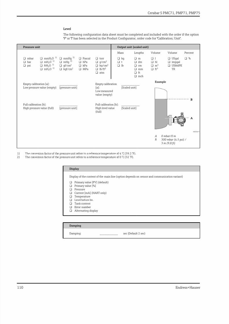
7/24/2019 Cerabar S PMC71, PMP71, PMP75
http://slidepdf.com/reader/full/cerabar-s-pmc71-pmp71-pmp75 110/116
Cerabar S PMC71, PMP71, PMP75
110 Endress+Hauser
Level
The following configuration data sheet must be completed and included with the order if the option "F" or "I" has been selected in the Product Configurator, order code for "Calibration; Unit".
Pressure unit Output unit (scaled unit)
Mass Lengths Volume Volume Percent
mbarbarpsi
mmH2O 1)
mH2O 1)
ftH2O 1)
inH2O 1)
mmHg 2)
inHg 2)
gf/cm2
kgf/cm2
PascalhPakPaMPa
torrg/cm2
kg/cm2
lb/ft2
atm
kgtlb
mdmcmmmftinch
lhlm3
ft3
USgalimpgalUSbblPETR
%
Example
A
B
A0020477
A 0 mbar/0 m B 300 mbar (4.5 psi) /
3 m (9.8 ft)
Empty calibration [a]:Low pressure value (empty)
___________[pressure unit]
Empty calibration[a]:Low measured
value (empty)
___________[Scaled unit]
Full calibration [b]:High pressure value (full) ___________[pressure unit] Full calibration [b]:High level value(full)
___________[Scaled unit]
1) The conversion factor of the pressure unit refers to a reference temperature of 4 °C (39.2 °F).
2) The conversion factor of the pressure unit refers to a reference temperature of 0 °C (32 °F).
Display
Display of the content of the main line (option depends on sensor and communication variant)
Primary value [PV] (default)Primary value [%]PressureCurrent [mA] (HART only)TemperatureLevel before lin.Tank contentError number
Alternating display
Damping
Damping: ___________ sec (Default 2 sec)
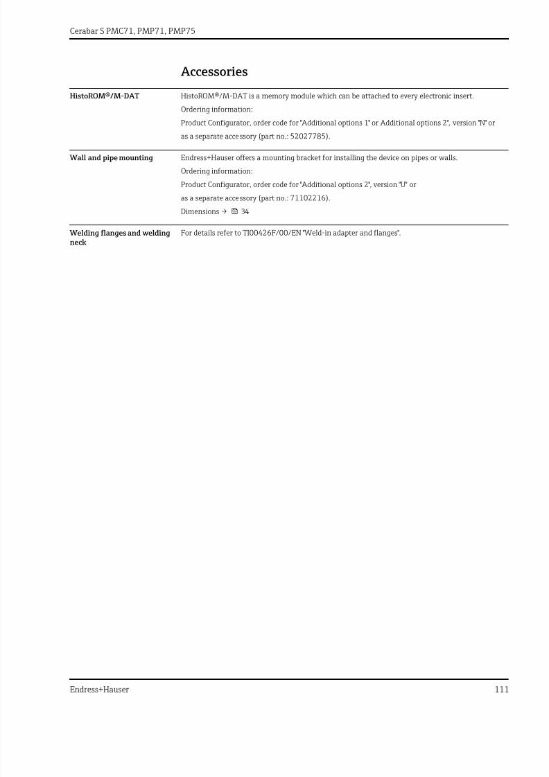
7/24/2019 Cerabar S PMC71, PMP71, PMP75
http://slidepdf.com/reader/full/cerabar-s-pmc71-pmp71-pmp75 111/116
Cerabar S PMC71, PMP71, PMP75
Endress+Hauser 111
Accessories
HistoROM®/M-DAT HistoROM®/M-DAT is a memory module which can be attached to every electronic insert.
Ordering information:
Product Configurator, order code for "Additional options 1" or Additional options 2", version "N" oras a separate accessory (part no.: 52027785).
Wall and pipe mounting Endress+Hauser offers a mounting bracket for installing the device on pipes or walls.
Ordering information:
Product Configurator, order code for "Additional options 2", version "U" or
as a separate accessory (part no.: 71102216).
Dimensions → 34
Welding flanges and weldingneck
For details refer to TI00426F/00/EN "Weld-in adapter and flanges".

7/24/2019 Cerabar S PMC71, PMP71, PMP75
http://slidepdf.com/reader/full/cerabar-s-pmc71-pmp71-pmp75 112/116
Cerabar S PMC71, PMP71, PMP75
112 Endress+Hauser
Supplementary documentation
Field of Activities Pressure measurement, powerful instruments for process pressure, differential pressure, level andflow:
FA00004P/00/EN
Technical Information • EMC test procedures: TI00241F/00/EN• Deltabar S: TI00382P/00/EN• Deltapilot S: TI00416P/00/EN• EMC test procedures: TI00241F/00/EN
Operating Instructions 4 to 20 mA HART:• Cerabar S: BA00271P/00/EN• Description of device functions Cerabar S/Deltabar S/Deltapilot S: BA00274P/00/EN
4 to 20 mA HART with MID parts certificate:• BA00412P/00/EN• Description of Device Functions: BA00413P/00/EN
PROFIBUS PA:• Cerabar S: BA00295P/00/EN• Description of device functions Cerabar S/Deltabar S/Deltapilot S: BA00296P/00/EN
FOUNDATION Fieldbus:• Cerabar S: BA00302P/00/EN• Description of device functions Cerabar S/Deltabar S/Deltapilot S: BA00303P/00/EN
Brief Operating Instructions • 4 to 20 mA HART, Cerabar S: KA01019P/00/EN• PROFIBUS PA, Cerabar S: KA01022P/00/EN• FOUNDATION Fieldbus, Cerabar S: KA01025P/00/EN
Functional safety manual(SIL)
Cerabar S (4 to 20 mA): SD00190P/00/EN
Overfill protection WHG: ZE00260P/00/DE
Safety Instructions (XA) Depending on the approval, the following Safety Instructions (XA) are supplied with the device. They are an integral part of the Operating Instructions.
Directive Device Electronics Documentation Option 1)
ATEX II 1/2 G Ex ia IIC T6 PMC71, PMP71, PMP75 4 to 20 mA HART, PROFIBUS PA,FOUNDATION Fieldbus
XA00244P 1
ATEX II 1/2 D Ex ia PMP71, PMP75 4 to 20 mA HART, PROFIBUS PA,FOUNDATION Fieldbus
• XA00246P• XA00289P
2
ATEX II 1/2D Ex tD PMC71 4 to 20 mA HART, PROFIBUS PA,FOUNDATION Fieldbus • XA00247P• XA00290P 2
ATEX II 1/3D Ex tD PMP71, PMP75 4 to 20 mA HART, PROFIBUS PA,FOUNDATION Fieldbus
• XA00248P• XA00291P
4
ATEX II 2G Ex d IIC T6 Gb PMP71, PMP75 4 to 20 mA HART, PROFIBUS PA,FOUNDATION Fieldbus
XA00249P 5
ATEX II 2G Ex d [ia] IIC T6 Gb PMC71 4 to 20 mA HART, PROFIBUS PA,FOUNDATION Fieldbus
XA00250P 5
ATEX II 1/2G Ex ia IIC T6, WHG (German Water Resources Act)
PMC71, PMP71, PMP75 4 to 20 mA HART, PROFIBUS PA,FOUNDATION Fieldbus
XA00244P 6
ATEX II 3 G Ex nA II T6 PMC71, PMP71, PMP75 4 to 20 mA HART, PROFIBUS PA,FOUNDATION Fieldbus
XA00251P 7
ATEX II 1/2G Ex ia + II 1/2D Ex iaD PMC71, PMP71, PMP75 4 to 20 mA HART, PROFIBUS PA,FOUNDATION Fieldbus
XA00253P 3

7/24/2019 Cerabar S PMC71, PMP71, PMP75
http://slidepdf.com/reader/full/cerabar-s-pmc71-pmp71-pmp75 113/116
Cerabar S PMC71, PMP71, PMP75
Endress+Hauser 113
Directive Device Electronics Documentation Option 1)
ATEX II 1G Ex ia + II 1D Ex iaD PMC71, PMP71, PMP75 4 to 20 mA HART, PROFIBUS PA,FOUNDATION Fieldbus
XA00276P 8
ATEX II 1/2G Ex ia IIC T6+II 2G Ex d IIC T6 PMP71, PMP75 4 to 20 mA HART, PROFIBUS PA,FOUNDATION Fieldbus
XA00252P B
ATEX II Ex ia + FM IS + CSA IS ATEX II1/2G Ex ia IIC T6 + FM/CSA IS Cl.I,II,III Div.1 Gr.A-G, FM/CSA: Zone 0,1,2
PMC71 • 4 to 20 mA HART, PROFIBUS PA,FOUNDATION Fieldbus
• HART• PROFIBUS PA, FOUNDATION Fieldbus
• XA00244P• XA00593P +
XA01059P• XA00596P +
XA01060P
E
ATEX II Ex ia / Ex d + FM/CSA IS + XP ATEX II 1/2G Ex ia IIC T6+ ATEX II 2G Ex d
IIC T6+ FM/CSA IS + XP Cl. I.II Div.1 Gr.A-G/B-G FM: Zone 1.2/CSA: Zone 1,2
PMP71, PMP75 • 4 to 20 mA HART, PROFIBUS PA,FOUNDATION Fieldbus
• HART• PROFIBUS PA, FOUNDATION Fieldbus
• XA00252P• XA00592P +
XA01197P• XA00590P +
XA01198P
F
1) Product Configurator, order code for "Approval"
Directive Device Electronics Documentation Option 1)
IECEx Zone 0/1 Ex ia IIC T6 PMC71, PMP71, PMP75 4 to 20 mA HART XB00005P I
IEC Ex d[ia] IIC T6 Gb PMC71 4 to 20 mA HART, PROFIBUS PA, FOUNDATION Fieldbus XA00511P B
IEC Ex d IIC T6 Gb PMP71, PMP75 4 to 20 mA HART, PROFIBUS PA, FOUNDATION Fieldbus XA00510P M
1) Product Configurator, order code for "Approval"
Directive Device Electronics Documentation Option 1)
NEPSI Ex ia IIC T6 PMC71, PMP71, PMP75 4 to 20 mA HART, PROFIBUS PA, FOUNDATION Fieldbus XA00549P H
NEPSI Ex d IIC T6 PMP71, PMP75 4 to 20 mA HART, PROFIBUS PA, FOUNDATION Fieldbus XA00551P GNEPSI Ex d[ia] IIC T6 PMC71 4 to 20 mA HART, PROFIBUS PA, FOUNDATION Fieldbus XA00551P G
1) Product Configurator, order code for "Approval"
Directive Device Electronics Documentation Option 1)
TIIS Ex d [ia] IIC T6 PMC71 4 to 20 mA HART TC17436 L
TIIS Ex d [ia] IIC T4 PMC71 4 to 20 mA HART TC17398, TC17399 M
TIIS Ex d IIC T6 PMP71 (700 bar version)
4 to 20 mA HART TC17445 L
TIIS Ex d IIC T6 PMP71, PMP75 4 to 20 mA HART TC17446 L
1) Product Configurator, order code for "Approval"
Directive Device Electronics Documentation Option 1)
INMETRO Ex ia IIC T6 Ga/Gb PMC71, PMP71, PMP75 4 to 20 mA HART, PROFIBUS PA, FOUNDATION Fieldbus XA01315P J
INMETRO Ex d IIC T6 Gb PMP71, PMP75 4 to 20 mA HART, PROFIBUS PA, FOUNDATION Fieldbus XA01279P O
INMETRO Ex ta IIIC Da/Db PMP71, PMP75 4 to 20 mA HART, PROFIBUS PA, FOUNDATION Fieldbus XA01313P Z
INMETRO Ex d ia IIC T6 Gb PMC71 4 to 20 mA HART, PROFIBUS PA, FOUNDATION Fieldbus XA01280P P
INMETRO Ex ia IIIC Da/Db PMC71 4 to 20 mA HART, PROFIBUS PA, FOUNDATION Fieldbus XA01314P Z
1) Product Configurator, order code for "Approval"

7/24/2019 Cerabar S PMC71, PMP71, PMP75
http://slidepdf.com/reader/full/cerabar-s-pmc71-pmp71-pmp75 114/116
Cerabar S PMC71, PMP71, PMP75
114 Endress+Hauser
Installation/ControlDrawings
Directive Device Electronics Documentation Option 1)
FM IS Class I, II, III, Division 1, Groups A – G;NI, Class I Division 2, Groups A – D; AEx ia
PMC71, PMP71, PMP75 • 4 to 20 mA HART• PROFIBUS PA, FOUNDATION Fieldbus
• XA01059P• XA01060P
S
CSA IS Class I, II, III, Division 1, Groups A – G;Class I Division 2, Groups A – G
PMC71, PMP71, PMP75 • 4 to 20 mA HART• PROFIBUS PA, FOUNDATION Fieldbus
• XA00593P• XA00596P
U
FM IS + XP Class I, Division 1, Groups A – D PMP71, PMP75 • 4 to 20 mA HART• PROFIBUS PA, FOUNDATION Fieldbus
• XA01197P• XA01198P
C
CSA IS + XP Class I Division 1, Groups A – D PMP71, PMP75 • 4 to 20 mA HART• PROFIBUS PA, FOUNDATION Fieldbus
• XA00592P• XA00590P
D
FM/CSA IS + XP Class I Division 1, Groups A – D
PMP71, PMP75 • 4 to 20 mA HART• PROFIBUS PA, FOUNDATION Fieldbus
• XA00592P + XA01197P
• XA01198P + XA00590P
E
FM NI Cl.I Div.2 Groups A - D, Zone 2 PMC71, PMP71, PMP75 4 to 20 mA HART, PROFIBUS PA,FOUNDATION Fieldbus
XA01063P R
FM XP Cl.I Div.1 Groups A - D, AEx d, Zone1,2
PMC71, PMP71, PMP75 4 to 20 mA HART, PROFIBUS PA,FOUNDATION Fieldbus
XA01070P T
FM DIP Cl.II,III Div.1 Gr.E-G, Zone 21,22 PMP71, PMP75 4 to 20 mA HART, PROFIBUS PA,FOUNDATION Fieldbus
FM3017778 Q
CSA C/US XP Cl.I Div.1 Gr.B-D, Ex d, Zone1,2
PMC71, PMP71, PMP75 4 to 20 mA HART, PROFIBUS PA,FOUNDATION Fieldbus
ZD00230P + XA00599P
V
CSA C/US General Purpose PMD75, FMD77,FMD78
4 to 20 mA HART, PROFIBUS PA,FOUNDATION Fieldbus
- X
1) Product Configurator, order code for "Approval"

7/24/2019 Cerabar S PMC71, PMP71, PMP75
http://slidepdf.com/reader/full/cerabar-s-pmc71-pmp71-pmp75 115/116
Cerabar S PMC71, PMP71, PMP75
Endress+Hauser 115
Registered trademarks
HART® Registered trademark of the HART Communication Foundation, Austin, USA
PROFIBUS® Registered trademark of the PROFIBUS User Organization, Karlsruhe, Germany
FOUNDATION ™ Fieldbus Registered trademark of the Fieldbus Foundation, Austin, Texas, USA
PatentsThis product is protected by at least one of the following patents. Further patents are pending.
DE patents US patents EP patents
- US 5,836,063 A1 EP 0 797 084 B1
- US 5,877,424 A1 EP 0 780 674 B1
DE 203 05 869 U1 - -
- US 6,363,790 A1 EP 0 995 979 B1
- US 5,670,063 A1 EP 0 516 579 B1
- US 5,539,611 A1 -
- US 5,050,034 A1 EP 0 445 382 B1
- US 5,005,421 A1 EP 0 351 701 B1
- - EP 0 414 871 B1
- - EP 1 061 351 B1
- US 5,334,344 A1 EP 0 490 807 B1
- US 6,703,943 A1 -

7/24/2019 Cerabar S PMC71, PMP71, PMP75
http://slidepdf.com/reader/full/cerabar-s-pmc71-pmp71-pmp75 116/116