Embed Size (px)
Citation preview
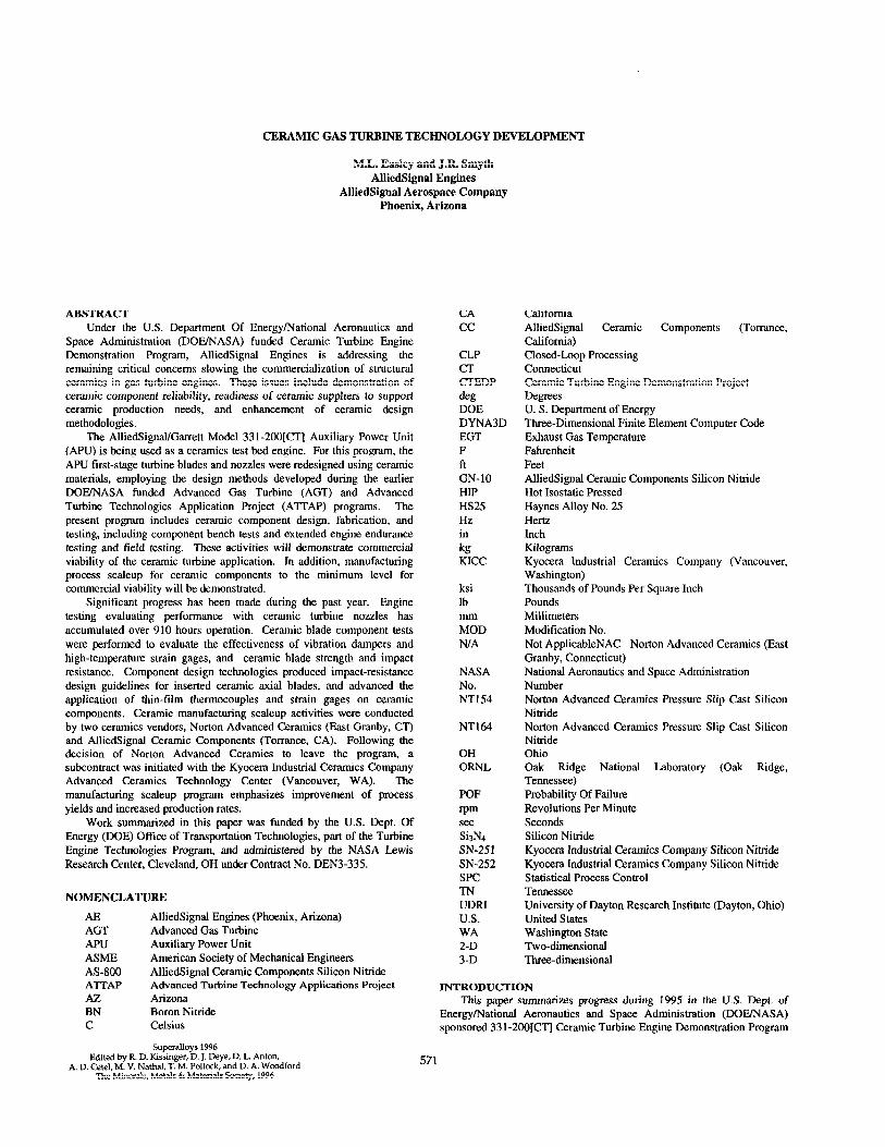
CERAMIC GAS TURBINE TECHNOLOGY DEVELOPMENT
M.L. Easley and J.R. Smyth AlliedSignal Engines
AlliedSignal Aerospace Company Phoenix, Arizona
ABSTRACT Under the U.S. Department Of Energy/National Aeronautics and
Space Administration (DOE/NASA) funded Ceramic Turbine Engine Demonstration Program, AlliedSignal Engines is addressing tbe remaining critical concerns slowing the commercialization of structural ceramics in gas turbine engines. These issues include demonstration of ceramic component reliability, readiness of ceramic suppliers to support ceramic production needs, and enhancement of ceramic design methodologies.
The AlliedSignal/Garrett Model 331-2OO[CT] Auxiliary Power Unit (APU) is being used as a ceramics test bed engine. For this program, the APU first-stage turbine blades and nozzles were redesigned using ceramic materials, employing the design methods developed during the earlier DOE/NASA funded Advanced Gas Turbine (AGT) and Advanced Turbine Technologies Application Project (ATTAP) programs. The present program includes ceramic component design, fabrication, and testing, including component bench tests and extended engine endurance testing and field testing. These activities will demonstrate commercial viability of the ceramic turbine application. In addition, manufacturing process scaleup for ceramic components to the minimum level for commercial viability will be demonstrated.
Significant progress has been made during the past year. Engine testing evaluating performance with ceramic turbine nozzles has accumulated over 910 hours operation. Ceramic blade component tests were performed to evaluate the effectiveness of vibration dampers and high-temperature strain gages, and ceramic blade strength and impact resistance. Component design technologies produced impact-resistance design guidelines for inserted ceramic axial blades, and advanced the application of thin-film thermocouples and strain gages on ceramic components. Ceramic manufacturing scaleup activities were conducted by two ceramics vendors, Norton Advanced Ceramics (East Granby, CT) and AlliedSignal Ceramic Components (Torrance, CA). Following the decision of Norton Advanced Ceramics to leave the program, a subcontract was initiated with tbe Kyocera Industrial Ceramics Company Advanced Ceramics Technology Center (Vancouver, WA). The manufacturing scaleup program emphasizes improvement of process yields and increased production rates.
Work summarized in this paper was funded by the U.S. Dept. Of Energy (DOE) Office of Transportation Technologies, part of the Turbine Engine Technologies Program, and administered by the NASA Lewis Research Center, Cleveland, OH under Contract No. DEN3-335.
NOMENCLATURE
AE AGT APU ASME AS-800 AlTAP AZ BN C
AlliedSignal Engines (Phoenix, Arizona) Advanced Gas Turbine Auxiliary Power Unit American Society of Mechanical Engineers AlliedSignal Ceramic Components Silicon Nitride Advanced Turbine Technology Applications Project Arizona Boron Nitride Celsius
Superalloys 1996
CA cc
CLP CT CTEDP de DOE DYNA3D EGT F ft GN-10 HIP HS2.5 Hz in kg Klcc
ksi lb
ED N/A
NASA No. NTIS4
NT164
OH ORNL
POF rpm set Si3N4 SN-2.51 SN-252 SPC TN UDRI U.S. WA 2-D 3-D
California AlliedSignal Ceramic Components (Torrance, California) Closed-Loop Processing Connecticut Ceramic Turbine Engine Demonstration Project Degrees U. S. Department of Energy Three-Dimensional Finite Element Computer Code Exhaust Gas Temperature Fahrenheit Feet AlliedSignal Ceramic Components Silicon Nitride Hot lsostatic Pressed Haynes Alloy No. 25 Hertz Inch Kilograms Kyocera Industrial Ceramics Company (Vancouver, Washington) Thousands of Pounds Per Square Inch Pounds Millimeters Modification No. Not ApplicableNAC Norton Advanced Ceramics (East Granby, Connecticut) National Aeronautics and Space Administration Number Norton Advanced Ceramics Pressure Slip Cast Silicon Nitride Norton Advanced Ceramics Pressure Slip Cast Silicon Nitride Ohio Oak Ridge National Laboratory (Oak Ridge, Tennessee) Probability Of Failure Revolutions Per Minute Seconds Silicon Nitride Kyocera Industrial Ceramics Company Silicon Nitride Kyocera Industrial Ceramics Company Silicon Nitride Statistical Process Control Tennessee University of Dayton Research Institute (Dayton, Ohio) United States Washington State Two-dimensional Three-dimensional
INTRODUCTION This paper summarizes progress during 1995 in the U.S. Dept. of
Energy/National Aeronautics and Space Administration (DOE/NASA) sponsored 331-2@O[CT] Ceramic Turbine Engine Demonstration Program
Edited by R. D. Kissinger, D. J. Eye, D. L. Anton, A. D. C&l, M. V. Nathal, T. M. Pollock, and D. A. Woodford
‘Ihe Minerals, Metals&Materials Society, 1996
571
conducted by AlliedSignal Engines, Phoenix, AZ, a unit of AlliedSignal Aerospace Company, in developing the needed technologies for ceramic gas turbine engines. The Ceramic Turbine Engine Demonstration Project (CTEDP) is sponsored by the U.S. Department of Energy (WE) to develop the technology for an improved automobile propulsion system under Title Ill of U.S. Public Law 95-238, “Automotive Propulsion Research and Qevelopment Act of 1978.” The CTEDP program is authorized under DOE/NASA Contract DEN3-335, with the National Aeronautics and Space Administration (NASA) Lewis Research Center (Cleveland, OH) providing program management and administration.
The thrust of the CTEDP/331-2OO[CT] program is to “bridge the gap” between ceramics in the laboratory and near-term commercial heat engine applications. The intent is to use this application as a stepping stone to transition the technology into the automotive marketplace where its benefits can have the greatest impact on reducing fuel consumption and gaseous emissions.
As part of this overall effort, the CTEDP program will provide essential and substantial early field experience demonstrating the reliability and durability of ceramic components in modified, available, real engine applications, including manufacturing scaleup for competitive production. These efforts Will lead to accelerated commercialization of advanced, high-temperature engines in hybrid vehicles and other applications. Additional efforts supported by this project include the DOE-sponsored Propulsion Systems Materials program, which has the objectives of improving the manufacturing processes for ceramic turbine engine components and demonstrating application of these processes in the production environment.
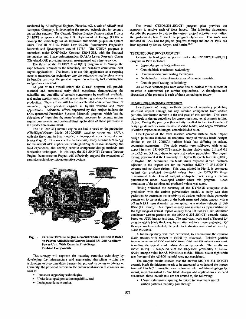
The 331-ZOO[CT] ceramic engine test bed is based on the production AUiedSignal/Garrett Model 331-2OO[ER] auxiliary power unit (APU), with the first-stage turbine modified to incorporate ceramic nozzles and blades (Fig. 1). This work will simultaneously ready ceramic technology for the aircraft APU application, while gathering extensive laboratory and field experience, and develop ceramic component design methods and fabrication techniques. In this way, the 331-3OO[CT] Ceramic Turbine Engine Demonstration Project will effectively support the expansion of ceramics technology into automotive designs.
Fig. 1. Ceramic Turbine Engine Demonstration Test Bed Is Based on Proven AlliedSignaUGarrett Model 331-200 Auxiliary Power Unit, With Ceramic First-Stage Turbine Components.
This strategy will augment the maturing ceramics technology by developing the infrastructure and engineering disciplines within the technology to overcome those barriers that prevent its commer-cialization. Currently, the principal barriers to the commercial-ization of ceramics are seen as:
l Immature supporting technologies, l Underdeveloped production capability, and l Inadequate demonstration.
The overall CTEDP/331-2OO[CT] program plan provides the approach to resolve each of these issues. The following discussions describe the progress to date in the various project activities and outline the go-forward plans to meet the program objectives. This work was initiated in 1993 and the project progress through the end of 1994 has been reported by Easley, Smyth, and Rettler.(‘**)
TECHNOLOGYDEVELOPMENT Ceramic technologies supported under the CTEDP/331-2OO[C’lJ
Program in 1995 included: l Impact design methods refinement l Ceramic blade attachment technology l Ceramic nozzle proof testing techniques l Oxidation/corrosion characteristics of ceramic materials l Ceramic proof testing methodology. All of these technologies were identified as critical to the success of
ceramics in commercial gas turbine applications. A description and discussion of the progress in each of these technologies follow.
ImDact Design Methods Develooment Development of design methods capable of accurately predicting
structural impact damage for any ceramic component from carbon particles (combustor carbon) is the end goal of this activity. This work will result in design guidelines for impact-resistant, axial ceramic turbine blades. During the past year this activity resulted in the development of design guidelines for axial ceramic inserted blades, and began evaluation of carbon impact on an integral ceramic bladed rotor.
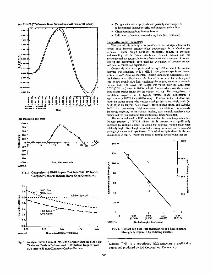
Development of the axial inserted ceramic turbine blade impact design guidelines included an analytical study of various blade designs similar to the 331-2OO[CT] turbine blade but differing in critical geometric parameters. The study results were calibrated with actual impact tests on 331-2OO[CT] ceramic turbine blades using 0.1 and 0.2 inch (2.5 and 5.1 mm) diameter spherical carbon projectiles. The impact testing, performed at the University of Dayton Research Institute (UDRI) in Dayton, OH, determined the blade strain response at two locations adjacent to the impact site for the baseline (MOD 0) 331-2OO[CT] ceramic turbine blade design. This data, plotted in Fig. 2, is compared against the predicted threshold values from the DYNA3D three- dimensional finite element analysis corn-puter code using a carbon pulverization model developed earlier under this program. Good correlation of the test data and predicted values was noted.
Having validated the accuracy of the DYNA3D computer code predictions with the carbon pulverization model, a study was then performed to determine the sensitivity of various turbine blade geometric parameters to the peak stress in the blade generated during impact with a 0.2 inch (5.1 mm) diameter carbon sphere at a relative velocity of 560 ft/sec (171 m/set). This impact velocity was selected as representative of the high range of critical impact velocity for a 0.2 inch (5.1 mm) diameter combustor carbon particle on the MOD 0 331-2OO[CT] ceramic blade, based on UDRI impact test data. The analytical work used a Taguchi L4 array in which blade thickness, taper ratio, and twist were evaluated. Of these parameters evaluated, the peak blade stresses were most affected by blade thickness.
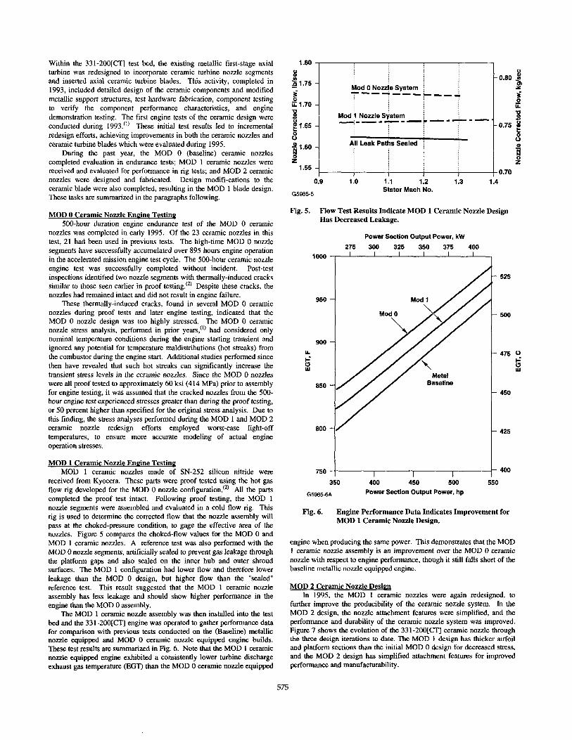
A follow-up study was then performed, to characterize the ceramic blade stresses with respect to airfoil tip thickness. Relative particle impact velocities of 1300 and 1600 ft/sec (396 and 488 m/set) were used, bounding the typical axial turbine design tip speeds. The results are shown in Fig. 3, compared with the lo-percent probability of failure (POF) strength value for AS-800 silicon nitride. Effects due to high strain rate fracture of the AS-800 material were not considered.
The analysis results showed that the current MOD 0 331-2OO[CT] ceramic blade tip thickness needs to be increased to withstand the impact from a 0.2 inch (5.1 mm) diameter carbon particle. Additional options for robust, impact-resistant turbine blade designs and applications also need evaluation; these include (but are not limited to) the following:
l Closer stator nozzle spacing, to reduce the maximum size of carbon particles that may pass through
572
(A) 331-200 (CT) Ceramic Blase Simulation at 431 ftlsec (131 mlsec)
(8) Measured Test Data
1000
800
600
-400 -600
600
-1000 I Time, Microseconds
G5985-2
Fig. 2. Comparison of UDRI Impact Test Data With DYNA3D Computer Code Predictions Shows Good Correlation.
IC--------------------------- AS-800 Strength
a 0.b; E
1
1300 Wsec /---
p 0.4 (396 dsec)
0.2 1
l Designs with lower tip speeds, and possibly more stages, to reduce impact damage severity and increase survivability
l Clean burning/carbon free combustors l Utilization of non-carbon-producing fuels (i.e., methanol).
Blade Attachment Technology The goal of this activity is to provide effective design solutions for
robust, axial inserted ceramic blade attachments for production gas turbines. These design solutions necessarily require a thorough understanding of the blade attachment contact stresses and the environmental and geometric factors that control these stresses. A contact test rig has successfully been used for evaluation of ceramic contact interfaces of various configurations.
Contact rig tests were performed during 1995 in which the contact interface was simulated with a MILB type ceramic specimen, loaded with a radiused Astroloy indenter. During these room temperature tests, the indentor was rubbed across the face of the ceramic bar with a pinch load of 300 pounds (136 kg), simulating the bearing stress on a ceramic turbine blade. The stroke (rub) length was varied over the range from 0.020 (0.51 mm) down to 0.006 inch (0.15 mm), which was the shortest controllable stroke length for the contact test rig. For comparison, the translation expected in a typical turbine blade attachment is approximately 0.003 inch (0.076 mm). Friction in the interface was modified during testing with various coatings, including cobalt oxide (an oxide layer on Haynes Alloy HS25), boron nitride (BN), and Lubcloc 7401’ (a proprietary high-temperature antifriction corn-pound). Following exposure to the contact loading, each ceramic specimen was then tested for retained room-temperature fast fracture strength.
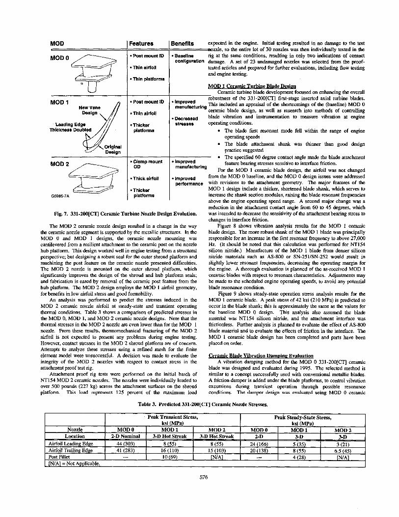
The tests conducted in 1995 confirmed that the room temperature fast fracture strength of NT154 silicon nitride ceramic was significantly degraded by rubbing contact in which the interface friction loads were relatively high. Rub length also had a strong influence on the retained strength of the ceramic specimens. This relationship is shown in the test data plotted in Fig. 4. Within the range of testing, it was found that the
140
1
120 -
.- p loo-
f ,tj EO-
e! a 2 i 60 -
.c
if 40-
20 -
0 I I I I 0 o.or 0.02 0.03 Oil
(0.003) (0.006) (0.009) (0.01 G5985-4A Stroke Length, inch, (mm)
1000
.750 m
;
is .500 e
ii ii 8 .E
f - 250
-0 0 2)
“.., 1 ~~
1.00
G5983-38
1.25 Ii0 1.;5
Normalized Blade Thickness
2.00 Fig. 4. Contact Rig Test Data Indicates NT154 Fast Fracture Strength Is Degraded by Rubbing Contact.
Fig. 3. Analysis Shows Current (MOD 0) Ceramic Turbine Blade Tip Thickness Needs to Be Increased to Withstand Impact From 0.20 inch (0.51 mm) Diameter Carbon Particle.
*Lubeloc 7401 is a proprietary high-temperature antifriction compound produced by EM Corporation, Connecticut.
573

number of cycles, the cumulative travel, and the type of lubricant CERAMIC COMPONENTS QUANTITY FABRICATION (coating) did not significantly affect the retained strength. DEMONSTRATION
Cyclic spin tests were also conducted, in which various anti-friction treatments were applied to several types of blade compliant layers, and assembled with ceramic test blades in a slotted metallic (engine hardware) turbine rotor disk. In this test series, 100 spin test cycles were performed on each rotor assembly at speeds from 4,000 to 42,000 rpm (representing 10 percent to 100 percent design speeds), after which the rotor was disassembled and the blades and compliant layer specimens were examined. The compliant layer configurations tested included pre- oxidized Haynes Alloy HS25 (Baseline), pm-oxidized HS25 with boron nitride (BN) applied via aerosol to both sides, and pm-oxidized HS25 coated with Lubeloc 7401 on the disk side only. The cyclic spin test msuhs am listed in Table 1. Based on these tests, neither the boron nitride (BN) or Lubeloc 7401 coatings performed better than the baseline pm-oxidized HS25.
The purpose of this activity is to develop the required capabilities of domestic ceramic engine component suppliers to support engine production. This activity will move the ceramic component fabrication processes out of the laboratory and into a production environment in which consistent, highquality components can be made economically.
Initiated in late 1993 and scheduled to continue through 1997, this subcontract work is focusing on the suppliers of the 331-2OO[CT] ceramic components for the Ceramic Turbine Engine Demonstration Program. The suppliers are being challenged to scale-up and improve their demonstrated fabrication processes to achieve production readiness. AlliedSignal Ceramic Components (CC, in Torrance, CA), and Norton Advanced Ceramics (NAC, in East Granby, CT) participated in this activity during 1995, with Kyocera Industrial Ceramics Company (KICC, in Vancouver, WA) initiating subcontract work at the end of the year.
Table 1. Compliant Layer Cyclic Spin Test Results.
Test Temperature
Compliant Layer Room
Temperature 1200F (6498
At the beginning of this activity, production processes for the volume manufacture of ceramic gas turbine components did not exist at the subcontractor facilities. The laboratory-based processes in use were typically capable of only producing less than 50 pieces per month, at overall yields of less than 25 percent acceptable parts. At the conclusion of the manufacturing scaleup and demonstration subcontract activity, each of the participating manufacturers will have achieved the goals listed in Table 2.
Pre-oxidized HS25 No weac No wear through (Baseline) through
Pm-oxidized HS25 with BN Wear through (Not tested)
Pre-oxidized HS25 with No wear Severe gaging Lubeloc 7401 through
Table 2. Ceramic Component Manufacturing Scaleup Goals.
Ceramic Nozzle Proof Testing Techniaues The focus of this effort is to identify cost-effective proof testing
techniques to ensure the quality of ceramic hardware prior to engine installation. The goals are to develop proof testing methods that are accurate, yet inexpensive, that may potentially be used by the ceramic component manufacturers and users. Work during 1995 resulted in the design and fabrication of three test rigs for proof testing the 331-2OO[CT] MOD 2 ceramic nozzles. One of the rigs, intended to test the nozzles with respect to attachment loads, was functionally evaluated with actual ceramic nozzles and used to proof test a set of parts received in preparation for engine testing. Evaluations of the other two rigs, the airfoil test rig and the fillet test rig, are planned for early 1996.
Item Individual Process Capability
Overall Yield Overall Process Capacity
Goal 500
Parts/Month 75 Percent
100 Parts/Month (Demonstrated)
Ceramic Proof Test Methods This activity, in collaboration with the ongoing DOE-sponsored
Phase II Life Prediction Methodology For Ceramic Components of Advanced Heat Engines Program, is being performed by AlliedSignal Engines and managed by the DOE Oak Ridge National Laboratory (ORNL). This work will establish the reliability of proof testing of ceramic components with respect to volume flaws. (Additonal work to establish ceramic component reliability with respect to surface flaws is being performed by AlliedSignal Engines under the DOE/ORNL sponsored Phase II Life Prediction Program, and is not reported here.) This complementary work under both programs will prove extremely useful in defining the types of proof tests and the test criteria for future ceramic components.
By the end of 1994, CC demonstrated the feasibility of AS-800 silicon nitride as a potentially lower-cost turbine component material with respect to both material properties and shape capability. This demonstration enabled CC to replace GN-10 with AS-800 as the ceramic material for the planned 1995 scaleup demonstration. AS-800 is a gas- pressure-sintered silicon nitride that has the potential for lower component fabrication costs compared to GN-10, which is a glass- encapsulated, hot isostatic pressed (HIPped) material. In addition, AS- 800 has superior as-processed surface properties, better elevated- temperature fast-fracture and stress-rupture properties, and exhibits very high Weibull characteristics in each of these strength categories compared to GN-10. During 1995, CC made several AS-800 process improvements, increasing capacity for slip preparation, pre-sintering, and drying. In addition, CC deployed short-run statistical process control (SPC) in the AS-800 slip preparation and pre-sintering processes.
NAC focused their 1995 activities on the elimination of iron inclusions and demonstration of closed-loop processing (CLP) of NT164 silicon nitride components. This work was completed by mid-year, at which time NAC announced their business decision to discontinue production of gas turbine engine ceramics and subsequently terminated participation in this program.
Ceramic tensile test specimens have been procured to determine the effect of room-temperature proof testing on elevated-temperature fast fracture and time-dependent failure modes for volume-distributed flaws. The goal is to determine if proof testing affects the component integrity. The test specimens have been divided into two groups: one group initially received proof testing, with criteria selected to fail 30 percent of the specimens; the other group has not been proof tested. All of the specimens will be further tested to failure in high-temperature tensile fast- fracture and tensile stress-rupture, to determine whether the failure populations were truncated or modified by the proof testing.
AlliedSignal Engines initiated ceramic manufacturing scateup and demonstration activities with KICC during the third quarter of 1995. Before the end of the year, KICC had successfully formed one lot of SN- 252 silicon nitride ceramic nozzles using their hybrid molding process, achieving a green-forming yield of 70 percent.
ENGINE DEMONSTRATIONS Ceramic turbine engine demonstration activities began under the
present program during 1992, with selection of the AlliedSignal/ Garrett Model 331-2OO[ER] APU, a fully-developed gas turbine in production with current applications in the Boeing 757 and 767 aircraft, for modification into the ceramic turbine engine demonstration test bed.
574
Within the 331-2OO[CT] test bed, the existing metallic first-stage axial turbine was redesigned to incorporate ceramic turbine nozzle segments and inserted axial ceramic turbine blades. This activity, completed in 1993, included detailed design of the ceramic components and modified metallic support structures, test hardware fabrication, component testing to verify the component performance characteristics, and engine demonstration testing. The first engine tests of the ceramic design were conducted during 1993. (I) These initial test results led to incremental redesign efforts, achieving improvements in both the ceramic nozzles and ceramic turbine blades which were evaluated during 1995.
During the past year, the MOD 0 (baseline) ceramic nozzles completed evaluation in endurance tests; MOD 1 ceramic nozzles were received and evaluated for performance in rig tests; and MOD 2 ceramic nozzles were designed and fabricated. Design moditi-cations to the ceramic blade were also completed, resulting in the MOD 1 blade design. These tasks are summarized in the paragraphs following.
MOD 0 Ceramic Nozzle Engine Testing 500-hour duration engine endurance test of the MOD 0 ceramic
nozzles was completed in early 1995. Of the 23 ceramic nozzles in this test, 21 had been used in previous tests. The high-time MOD 0 nozzle segments have successfully accumulated over 895 hours engine operation in the accelerated mission engine test cycle. The 500-hour ceramic nozzle engine test was successfully completed without incident. Post-test inspections identified two nozzle segments with thermally-induced cracks similar to those seen earlier in proof testing.“’ Despite these cracks, the nozzles had remained intact and did not result in engine failure.
These thermally-induced cracks, found in several MOD 0 ceramic nozzles during proof tests and later engine testing, indicated that the MOD 0 nozzle design was too highIy stressed. The MOD 0 ceramic nozzle stress analysis, performed in prior years,(‘) had considered only nominal temperature conditions during the engine starting transient and ignored any potential for temperature maldistributions (hot streaks) from the combustor during the engine start. Additional studies performed since then have revealed that such hot streaks can significantly increase the transient stress levels in the ceramic nozzles. Since the MOD 0 nozzles were all proof tested to approximately 60 ksi (414 MPa) prior to assembly for engine testing, it was assumed that the cracked nozzles from the 500- hour engine test experienced stresses greater than during the proof testing, or 50 percent higher than specified for the original stress analysis. Due to this finding, the stress analyses performed during the MOD 1 and MOD 2 ceramic nozzle redesign efforts employed worst-case light-off temperatures, to ensure more accurate modeling of actual engine operation stresses.
MOD 1 Ceramic Nozzle En&e Testing MOD 1 ceramic nozzles made of SN-252 silicon nitride were
received from Kyocera. These parts were proof tested using the hot gas flow rig developed for the MOD 0 nozzle configuration.(‘) All the parts completed the proof test intact. Following proof testing, the MOD 1 nozzle segments were assembled and evaluated in a cold flow rig. This rig is used to determine the corrected flow that the nozzle assembly will pass at the choked-pressure condition, to gage the effective area of the nozzles. Figure. 5 compares the choked-flow values for the MOD 0 and MOD 1 ceramic nozzles. A reference test was also performed with the MOD 0 nozzle segments, artificially sealed to prevent gas leakage through the platform gaps and also sealed on the inner hub and outer shroud surfaces. The MOD 1 configuration had lower flow and therefore lower leakage than the MOD 0 design, but higher flow than the “sealed” reference test. This result suggested that the MOD 1 ceramic nozzle assembly has less leakage and should show higher performance in the engine than the MOD 0 assembly.
The MOD 1 ceramic nozzle assembly was then installed into the test bed and the 331-2OO[CT] engine was operated to gather performance data for comparison with previous tests conducted on the (Baseline) metallic nozzle equipped and MOD 0 ceramic nozzle equipped engine builds. These test results are summarized in Fig. 6. Note that the MOD 1 ceramic nozzle equipped engine exhibited a consistently lower turbine discharge exhaust gas temperature (EGT) than the MOD 0 ceramic nozzle equipped
Mod 1 Nozzle &stem y---~--+--+--.
F
-0.75 E
A’II Leak Paths Sealed j
I I I , 0.70
0.S 1.0 1.1 1.2 1.3 1.4
05985.5 Stator Mach No.
Fig. 5. Flow Test Results Indicate MOD 1 Ceramic Nozzle Design Has Decreased Leakage.
Power Section Output Power, kW
276 300 326 350 375 400
1000
950
900
LL
E
850
800
750
525
-500
475 0
5
450
.425
.400
350 400 460 500
G5985-6A Power Section Output Power, hp
550
Fig. 6. Engine Performance Data Indicates Improvement for MOD 1 Ceramic Nozzle Design.
engine when producing the same power. This demonstrates that the MOD 1 ceramic nozzle assembly is an improvement over the MOD 0 ceramic nozzle with respect to engine performance, though it still falls short of the baseline metallic nozzle equipped engine.
MOD 2 Ceramic Nozzle Desian In 1995, the MOD 1 ceramic nozzles were again redesigned, to
further improve the producibility of the ceramic nozzle system. In the MOD 2 design, the nozzle attachment features were simplified, and the performance and durability of the ceramic nozzle system was improved. Figure 7 shows the evolution of the 331-2OO[CT] ceramic nozzle through the three design iterations to date. The MOD 1 design has thicker airfoil and platform sections than the initial MOD 0 design for decreased stress, and the MOD 2 design has simplified attachment features for improved performance and manufactnrability.
575
MOD Ir Leatures
l Post mount ID
l Thin airfoil
l Thin platforms
MOD 1
MoD2a u G5985-7A
l Post mount ID
l Thin airfoil
l Thicker platforms
l Clamp mount OD
. Thick airfoil
l Thicker platforms
lenefits expected in the engine. Initial testing resulted in no damage to the test --&le, so the en& lot of 30 nozzles-was then individually-tested in the l Basellne rig at the same conditions, resulting in only two indications of contact
COnfiW~tiOn damage. A set of 23 undamaged nozzles was selected from the proof- tested articles and prepared for further evaluations, including flow testing and engine testing.
MOD 1 Ceramic Turbine Blade Desian Ceramic turbine blade development focused on enhancing the overall
l Improved robustness of the 331-2OO[CT] first-stage inserted axial turbine blades.
manufactur,ng This included an appraisal of the shortcomings of the (baseline) MOD 0 ceramic blade design, as well as research into methods of controlling
9 Decreased blade vibration and instrumentation to measure vibration at engine stresses operating conditions.
l The blade first resonant mode fell within the range of engine operating speeds
l Improved manufacturing
9 Improved performance
l The blade attachment shank was thinner than good design practice suggested
l The specified 60 degree contact angle made the blade attachment feature bearing stresses sensitive to interface friction.
For the MOD 1 ceramic blade design. the airfoil was not charmed from the MOD 0 baseline, and the MODO’design issues were addressed with revisions to the attachment geometry. The major features of the MOD 1 design include a thicker, shortened blade shank, which serves to increase the shank section modulus, raising the blade resonant frequencies above the engine operating speed range. A second major change was a reduction in the attachment contact angle from 60 to 45 degrees, which was intended to decrease the sensitivity of the attachment bearing stress to changes in interface friction.
Fig. 7. 331.20O[CT] Ceramic Turbine Nozzle Design Evolution.
The MOD 2 ceramic nozzle design resulted in a change in the way the ceramic nozzle segment is supported by the metallic structures. In the MOD 0 and MOD 1 designs, the ceramic nozzle mounting was cantilevered from a resilient attachment to the ceramic post on the nozzle hub platform. This design worked well in engine testing from a structural perspective; but designing a robust seal for the outer shroud platform and machining the post feature on the ceramic nozzle presented difficulties. The MOD 2 nozzle is mounted on the outer shroud platform, which significantly improves the design of the shroud and hub platform seals; and fabrication is eased by removal of the ceramic post feature from the hub platform. The MOD 2 design employs the MOD 1 airfoil geometry, for benefits in low airfoil stress and good formability.
An analysis was performed to predict the stresses induced in the MOD 2 ceramic nozzle airfoil at steady-state and transient operating thermal conditions. Table 3 shows a comparison of predicted stresses in the MOD 0, MOD 1, and MOD 2 ceramic nozzle designs. Note that the thermal stresses in the MOD 2 nozzle ate even lower than for the MOD 1 nozzle. From these results, thermomechanical fracturing of the MOD 2 airfoil is not expected to present any problems during engine testing. However, contact stresses in the MOD 2 shroud platform are of concern. Attempts to analyze these stresses using a refined mesh for the finite element model were unsuccessful. A decision was made to evaluate the integrity of the MOD 2 nozzles with respect to contact stress in the attachment proof test rig.
Attachment proof rig tests were performed on the initial batch of NT154 MOD 2 ceramic nozzles. The nozzles were individually loaded to over 500 pounds (227 kg) across the attachment surfaces on the shroud platform. This load represents 125 percent of the maximum load
Figure 8 shows vibration analysis results for the MOD 1 ceramic blade design. The mote robust shank of the MOD 1 blade was principally responsible for an increase in the first resonant frequency to above 27,000 Hz. (It should be noted that this calculation was performed for NT154 silicon nitride.) Manufacture of the MOD 1 blade from denser silicon nitride materials such as AS-800 or SN-251/SN-252 would result in slightly lower resonant frequencies, decreasing the operating margin for the engine. A thorough evaluation is planned of the as-received MOD 1 ceramic blades with respect to resonant characteristics. Adjustments may be made to the scheduled engine operating speeds, to avoid any potential blade resonance condition.
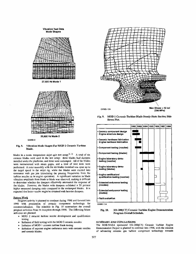
Figure 9 shows steady-state operation stress analysis results for the MOD 1 ceramic blade. A peak stress of 42 ksi (210 MPa) is predicted to occur in the blade shank; this is approximately the same as the values for the baseline MOD 0 design. This analysis also assumed the blade material was NT154 silicon nitride, and the attachment interface was frictionless. Further analysis is planned to evaluate the effect of AS-800 blade material and to evaluate the effects of friction in the interface. The MOD 1 ceramic blade design has been completed and parts have been placed on order.
Ceramic Blade Vibration DamDine Evaluation A vibration damping method for the MOD 0 331-2OO[CT] ceramic
blade was designed and evaluated during 1995. The selected method is similar to a concept successfully used with conventional metallic blades. A friction damper is added under the blade platforms, to control vibration excursions during transient operation through possible resonance conditions. The damper design was evaluated using MOD 0 ceramic
Table 3. Predicted 331-2OO[CTI Ceramic Nozzle Stresses.
576
Vibration Test Data Mode Shapes
27,500 Hz Mode 1
39,800 Hz Mode 2
G5985-9
Fig. 8. Vibration Mode Shapes For MOD 1 Ceramic Turbine Blade.
blades in a room- temperature airjet spin test setup.‘tB ‘) A total of six ceramic blades were used in the test setup: three blades had dampers installed under the platforms, and three were undamped. All of the blades were instrumented with strain gages, and a total of nine tests were performed. A rotor assembly with the six blades installed was spun up to the target speed in the airjet rig, while the blades were excited into resonance with gas jets (simulating the passing frequencies from the turbine nozzles as in engine operation). A significant variation in blade vibration amplitude from blade to blade was observed, making it difficult to determine whether the dampers effectively attenuated the response of the blades. However, the blades with dampers exhibited a 30 percent higher measured damping ratio compared to the undamped blades. It is expected that better results might be obtained with heavier dampers.
Future Work Program activity is planned to continue during 1996 and forward into _ _
1998 with preparation of ceramic component technology for commercialization. The schedule in Fig. 10 summarizes the overall program activities from its inception through 1998. The following future activities are planned:
. MOD 2 ceramic turbine nozzle development and qualification testing
. Initiation of field testing with the MOD 2 ceramic nozzles
. Initiation of MOD 1 ceramic turbine blade testing
. Initiation of separate engine endurance tests with ceramic nozzles and ceramic blades.
G5985-10A Max Stress = 42 ksl (290 MPa)
Fig. 9. MOD 1 Ceramic Turbine Blade Steady-State Suction Side Stress Plot.
l Ceramic component design Engine structure design
l Ceramic hardware fabrication Engine hardware fabrication
l Component testing (nozzles)
l Component testing (blades)
l Engine laboratory demo testing (nozzles)
l Engine laboratory demo testing (blades)
l Engine certification/ qualification testing (nozzles)
l Extended endurance testing (nozzles)
l Extended endurance testing (blades)
l Field evaluation
G5985-1 IA
Fig. 10. 331~2OO[CT] Ceramic Turbine Engine Demonstration Program Overall Schedule.
SUMMARY AND CONCLUSIONS The DDE-NASA sponsored 331-2OO[CT] Ceramic Turbine Engine Demonstration Project is planned to continue into 1998, with the mission of advancing ceramic gas turbine component technology towards
577

commercialization. Tbis will be accomplished by enhancing critical ceramic design technologies, scaling up and demonstrating production- level ceramic component manufacturing capability of domestic ceramics manufacturers, and demonstrating ceramic engine component durability and reliability in extensive laboratory and field engine tests.
During the past year, the design technologies for ceramic turbine blades were further advanced with completion of ceramic axial turbine blade impact design methodology development, ceramic blade impact testing, and a parametric study that produced guidelines for designing impact-resistant axial ceramic turbine blades. Investigations into the contact stress environment of the ceramic axial turbine blade attachment confirmed the importance of coatings to reduce friction and minimize contact stresses and also revealed the sensitivity of ceramic damage to translation (rub) length.
In the ceramic component manufacturing scaleup and demonstration activities, AlliedSignal Ceramic Components and Norton Advanced Ceramics (NAC) completed work necessary to justify a change to new ceramic materials and production processes that were more amenable to quantity production and improved quality. Due to business reasons, NAC opted to leave the program. Kyocera Industrial Ceramics Company was invited to join the program and began forming components.
Successful engine testing with the (baseline design) MOD 0 ceramic nozzles continued. Coupled with additional testing of the redesigned MOD 1 ceramic nozzles, total cumulative ceramic nozzle engine test time increased to over 910 hours. Ceramic nozzle engine testing is summarized in Table 4. The MOD 1 nozzle testing confirmed that the new “robust“ airfoil geometry performed at least as well as the original MOD 0 design in engine performance testing. Further improvements were incoporated into the MOD 2 ceramic nozzle design and parts fabrication was initiated. The MOD 2 nozzle design is intended to reduce fabrication costs and improve yields.
Table 4. 331.2OO[CT] Ceramic Nozzle Engine Testing Summary.
Vibration dampers for the ceramic blades were designed and evaluated in airjet spin testing. These dampers, similar to friction dampers commonly used with metallic inserted blades, were found to add damping to tbe ceramic blade system. However, the measured damping was not sufficient to significantly reduce the ceramic blade airfoil strain values at resonance conditions. A new (MOD 1) ceramic turbine blade design was completed. The MOD 1 blade design features added improvements over tbe MOD 0 design, including: increased attachment stiffness; increased shank thickness, resulting in the blade resonant frequency raised out of the engine operating range; and new dovetail geometry, intended to reduce bearing stress sensitivity to interface friction.
Engine testing with ceramic nozzles is planned to continue, with the objective of validating the performance and integrity of the MOD 2 nozzle design, and qualifying tbe 331-2OO[CT] ceramic nozzle for initiation of field testing, planned to begin in 1996. Engine testing of the ceramic turbine blades is planned to begin in early 1996, with a series of tests including blades with high-temperatnre thin-film strain gages, to measure ceramic turbine blade stress values during engine operation.
The 331-2OO[CT] Ceramic Turbine Engine Demonstration Project has the vision of augmenting the development of ceramic technology in support of automotive gas turbine development. To achieve this goal, the program plan is to enhance tire ceramic technologies required to support the design of gas turbine ceramic components, to refine and scale up the production capability of domestic ceramic component manufacturers, and to demonstrate the capabilities of the ceramic components, first in laboratory field tests and then in extensive field trials. Tbe engine demonstration and field evaluations will provide tbe experience required to verify the improvements in ceramic design technology and component fabrication. ACKNOWLEDGMENT
This paper was originally presented at the 41st ASME International Gas Turbine & Aercengine Congress, Exposition and Users Symposium on June 13, 19% in Birmingham, England. REFERENCES
1. M.L. Easley and J.R. Smyth, “Ceramic Gas Turbine Technology Development,” ASME Paper 94-GT-485, American Society of Mechanical Engineers, 1994.
2. M.W. Rettler, M.L. Easley, and J.R. Smyth, “Ceramic Gas Turbine Technology Development,” ASME Paper 95-GT-207, American Society of Mechanical Engineers, 1995.
578