Embed Size (px)
Citation preview

Ceramic Interconnects / Coatings
SECA Core Technology ProgramSECA Core Technology ProgramSOFC Interconnection (IC) Technology MeetingSOFC Interconnection (IC) Technology Meeting
Argonne National Laboratory, Chicago ILArgonne National Laboratory, Chicago ILJuly 28July 28--29, 200429, 2004

IC WorkshopIC Workshop July 28 July 28 -- 29, 200429, 2004 22
Interconnect Requirements
•• Thermal expansion match with SOFC componentsThermal expansion match with SOFC components•• Stability over operating pOStability over operating pO2 2 range (0.2 to 10range (0.2 to 10--18 18 atmatm))•• High electronic conductivity in air and fuelHigh electronic conductivity in air and fuel•• Gas impermeabilityGas impermeability•• Process compatibilityProcess compatibility•• Mechanical integrityMechanical integrity•• Low material and fabrication costsLow material and fabrication costs•• Negligible nonNegligible non--electronic migrationelectronic migration

IC WorkshopIC Workshop July 28 July 28 -- 29, 200429, 2004 33
Interconnect Materials•• Two classes of interconnect materialsTwo classes of interconnect materials
Ceramico suitable for high temp. operation (900 - 1000 C)o Electronic conductivity a strong function of temp.
Metallico suitable for 650 - 800 C operationo Oxidation is a major problem at higher temp.

IC WorkshopIC Workshop July 28 July 28 -- 29, 200429, 2004 44
Introduction and Background
- La(Sr)MnO3 - Cathode- La(Sr)CoO3 - Cathode- La(Sr)CrO3 - Interconnect- La(Sr)GaO3- Electrolyte
Typical Compositions of interestTypical Compositions of interest
- Good Conductivity (ionic, electronic) - OXYGEN NONSTOICHIOMETRY)
- Good Catalytic Propertiesfor Oxygen Exchange
- CTE flexibility(8.5 - 18.0 ppm / °C)
- Chemical Stability to Severe Conditions (LSCr)

IC WorkshopIC Workshop July 28 July 28 -- 29, 200429, 2004 55
Interconnect Requirements
•• Thermal Expansion Match with SOFC componentsThermal Expansion Match with SOFC components•• Stability over operating pOStability over operating pO2 2 rangerange•• High electronic conductivity in air and fuelHigh electronic conductivity in air and fuel
LaCrOLaCrO3 3 meets the necessary electrochemical properties meets the necessary electrochemical properties
•• Gas ImpermeabilityGas Impermeability•• Process CompatibilityProcess Compatibility•• Mechanical IntegrityMechanical Integrity

IC WorkshopIC Workshop July 28 July 28 -- 29, 200429, 2004 66
Challenges & Options in Fabrication
•• Difficult to sinter due to Difficult to sinter due to High Temperature requirements - typically ~ 1700 Ccontrol of CrO3 volatilization - Air Sintering is the preferred optioncapital and operational cost
•• OptionsOptionsLiquid Phase Sintering through addition of low melting eutecticTransient liquid phase sintering in the chromite system

IC WorkshopIC Workshop July 28 July 28 -- 29, 200429, 2004 77
Lower Temperature Air Sintering•• Addition of Ca and Co promotes liquid phase sinteringAddition of Ca and Co promotes liquid phase sintering•• Lower Sintering Temperature ~ 1450°CLower Sintering Temperature ~ 1450°C•• High Conductivity > 30 S/cm compared 10 S/cm for High Conductivity > 30 S/cm compared 10 S/cm for SrSr
doped doped LCrLCr

IC WorkshopIC Workshop July 28 July 28 -- 29, 200429, 2004 88
Sintering Characteristics of LaCrO3

IC WorkshopIC Workshop July 28 July 28 -- 29, 200429, 2004 99
Evaluation of Interconnect Compositions
•• Thermal Expansion BehaviorThermal Expansion Behavior
•• Stability in Fuel AtmosphereStability in Fuel Atmosphere
•• Mechanical PropertiesMechanical Properties

IC WorkshopIC Workshop July 28 July 28 -- 29, 200429, 2004 1010
Thermal Expansion Behavior

IC WorkshopIC Workshop July 28 July 28 -- 29, 200429, 2004 1111
Stability in Fuel AtmosphereOxygen Non-stoichiometry

IC WorkshopIC Workshop July 28 July 28 -- 29, 200429, 2004 1212
Stability in Fuel AtmosphereConductivity

IC WorkshopIC Workshop July 28 July 28 -- 29, 200429, 2004 1313
Mechanical PropertiesFracture Strength of La.89Ca.1Cr.9Co.1O3 in Fuel
0 time m = 9.130 sec m = 11.560 sec m = 14.5
Weibull Modulus

IC WorkshopIC Workshop July 28 July 28 -- 29, 200429, 2004 1414
Mechanical PropertiesFracture Strength of La.83Sr.16CrO3in Fuel

IC WorkshopIC Workshop July 28 July 28 -- 29, 200429, 2004 1515
Comparison of compositions•• LCCrLCCr
Low sintering tempHigh conductivity in airPoor stability in fuelLow mech. Properties
•• LSCrLSCrBetter stability in fuel
•• LMgCrLMgCrBest stabilityLow conductivity
Need to compare ionic transport

IC WorkshopIC Workshop July 28 July 28 -- 29, 200429, 2004 1616
Symptoms of Ionic Leakage•• Low OCVLow OCV•• Low Fuel UtilizationLow Fuel Utilization
Prior Measurements:Prior Measurements:•• WE:WE: Differential pODifferential pO22 Mg dopedMg doped <10 µA/cm<10 µA/cm22
gas Analysisgas Analysis
•• Tokyo Gas:Tokyo Gas: Conductivity Conductivity SrSr, Ca doped, Ca doped 1010--300 mA/ cm300 mA/ cm22
RelaxationRelaxation•• NIMCR:NIMCR: Limiting CurrentLimiting Current Ca dopedCa doped 1 mA/ cm1 mA/ cm22
•• Ceramatec:Ceramatec: InIn--line Sensorline Sensor SrSr dopeddoped 50 mA/ cm50 mA/ cm22

IC WorkshopIC Workshop July 28 July 28 -- 29, 200429, 2004 1717
Ionic Leakage Modeling*
•• 3D stack model 3D stack model -- thermal, electrochemical, electricalthermal, electrochemical, electrical
•• Input data: Tokyo Gas (Yasuda et al.)Input data: Tokyo Gas (Yasuda et al.)a)a) LaLa11--yyCaCayyCrOCrO33
b) Lab) La11--yySrSryyCrOCrO33
Lexp(18.72 YCa - 16000/T)j = 1152 (-logPo2-12)
2240 (-logPo2-12)exp(16.1 Y - 21000/T)
L Srj =
*work done at Institutt for energiteknikk, Norway

IC WorkshopIC Workshop July 28 July 28 -- 29, 200429, 2004 1818
Geometry Consideration
Geometry 1Geometry 1
Thickness(t): 0.36 mmThickness(t): 0.36 mm
Channel Depth(d): 0.71 mmChannel Depth(d): 0.71 mm
Channel Width(w): 1.7 mmChannel Width(w): 1.7 mm
w
d
Geometry 2Geometry 2
Thickness(t): 0.86 mmThickness(t): 0.86 mm
Channel Depth(d): 0.84 mmChannel Depth(d): 0.84 mm
Channel Width(w): 1.7 mmChannel Width(w): 1.7 mm
t2
IC WorkshopIC Workshop July 28 July 28 -- 29, 200429, 2004 1919
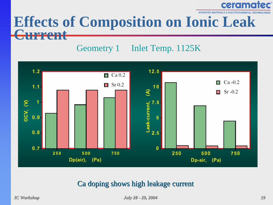
Effects of Composition on Ionic Leak Current
Geometry 1 Inlet Temp. 1125K
Ca doping shows high leakage currentCa doping shows high leakage current
IC WorkshopIC Workshop July 28 July 28 -- 29, 200429, 2004 2020
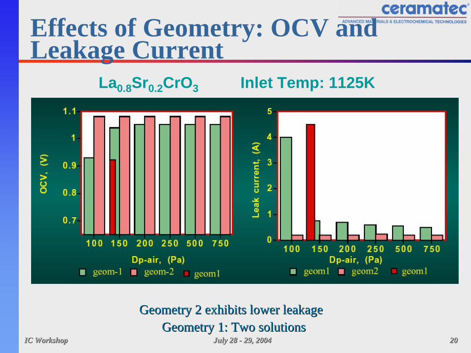
Effects of Geometry: OCV and Leakage Current
La0.8Sr0.2CrO3 Inlet Temp: 1125K
Geometry 2 exhibits lower leakageGeometry 2 exhibits lower leakageGeometry 1: Two solutionsGeometry 1: Two solutions

IC WorkshopIC Workshop July 28 July 28 -- 29, 200429, 2004 2121
Effects of Inlet Temperature: OCVGeometry 1 Geometry 2La0.8Sr0.2CrO3
•• OCV decreases with increasing tempOCV decreases with increasing temp•• OCV of geometry 2 is independent of OCV of geometry 2 is independent of Dp(airDp(air))

IC WorkshopIC Workshop July 28 July 28 -- 29, 200429, 2004 2222
Effects of Inlet Temperature: Leakage Current
Geometry 1 Geometry 2La0.8Sr0.2CrO3
•• Leakage current increases with increasing temp.Leakage current increases with increasing temp.•• Geometry 2 is insensitive to air pressureGeometry 2 is insensitive to air pressure

IC WorkshopIC Workshop July 28 July 28 -- 29, 200429, 2004 2323
Measurement Technique•• Direct measurement of ionic current is cumbersomeDirect measurement of ionic current is cumbersome•• Need an indirect measurement techniqueNeed an indirect measurement technique
Oxygen loss from the lattice causes lattice expansion

IC WorkshopIC Workshop July 28 July 28 -- 29, 200429, 2004 2424
Lattice Expansion in Fuel

IC WorkshopIC Workshop July 28 July 28 -- 29, 200429, 2004 2525
Characterization of Lanthanum Chromite
Composition Conductivity in Air S/cm
Conductivity in Fuel S/cm
Thermal Expansion to
1000°Cppm/°
CCE at 1000°Cin 3% H2 -
Argon
La.83Sr.13Ca.03CrO3 15 - 25 2 - 6 10.1 0.135%
La.83Sr.16Cr.98Fe.02O3 ~ 15 <1 10.4 0.088%
La.99Mg.1Cr.9O3 8 - 10 1 - 2 8.9 0.05%
La.99Mg.2Cr.8O3 4.44 0.45 9.5 0.077%
La.99Mg.1Cr.85Fe.05O3 5.86 1.01 9.23 0.035%
La.99Mg.1Cr.8Fe.1O3 4.02 0.61 9.32 0.044%
La.99Mg.1Cr.80Ti.10O3 0.62 0.56 9.02 0.025%
La.99Mg.1Cr.85Al.05O3 5.33 0.73 9.40 0.050%
La.99Mg.1Cr.8Al.10O3 8.33 0.86 9.90 0.065%
La.99Mg.1Cr.6 Al.3O3 3.85 0.101 10.4 0.07%
La.63Gd.2Sr.16CrO3 22.4 3.99 9.37 0.14%

IC WorkshopIC Workshop July 28 July 28 -- 29, 200429, 2004 2626
Fuel Induced Warpage

IC WorkshopIC Workshop July 28 July 28 -- 29, 200429, 2004 2727
Effect of fuel pO2 on OCV
IC WorkshopIC Workshop July 28 July 28 -- 29, 200429, 2004 2828
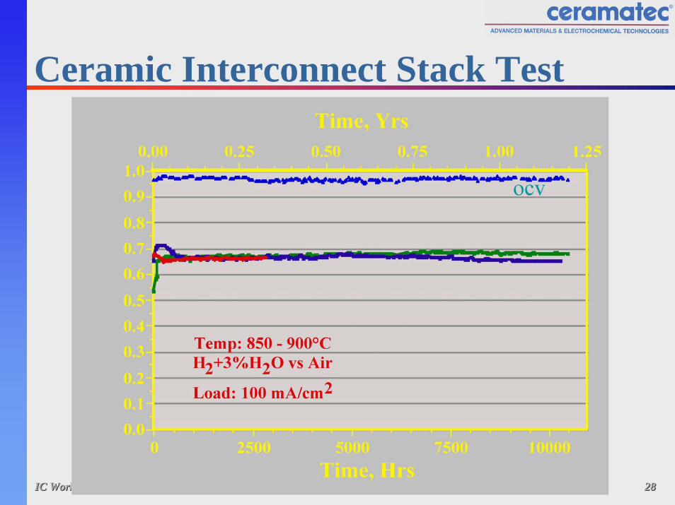
Ceramic Interconnect Stack Test

IC WorkshopIC Workshop July 28 July 28 -- 29, 200429, 2004 2929
Summary - Ceramic ICs•• Ionic leakage of chromite interconnects must be Ionic leakage of chromite interconnects must be
considered in the selection of material considered in the selection of material compositioncomposition
•• Global optimization of properties necessaryGlobal optimization of properties necessary•• Stack endurance demonstrated using this Stack endurance demonstrated using this
approachapproach•• Materials and fabrication costs need to be Materials and fabrication costs need to be
addressedaddressed

IC WorkshopIC Workshop July 28 July 28 -- 29, 200429, 2004 3030
Metal Interconnects
•• Additional RequirementsAdditional RequirementsHigh temperature corrosion resistanceScale conductivityScale adhesionStability against electrode/bond layer (poisoning effect)Thermal cycle capability

IC WorkshopIC Workshop July 28 July 28 -- 29, 200429, 2004 3131
Approach•• Controlled growth of conductive scale to achieveControlled growth of conductive scale to achieve
Electronic conductivity in scaleLow cation (metal) and anion (oxygen) diffusivityGood adhesion (‘native’ scale)
IC WorkshopIC Workshop July 28 July 28 -- 29, 200429, 2004 3232
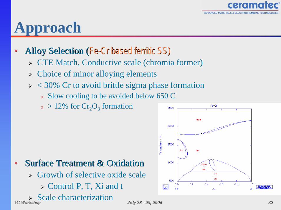
Approach•• Alloy Selection (Alloy Selection (FeFe--Cr based ferritic SS)Cr based ferritic SS)
CTE Match, Conductive scale (chromia former)Choice of minor alloying elements< 30% Cr to avoid brittle sigma phase formation
o Slow cooling to be avoided below 650 Co > 12% for Cr2O3 formation
•• Surface Treatment & OxidationSurface Treatment & OxidationGrowth of selective oxide scale
Control P, T, Xi and tScale characterization

IC WorkshopIC Workshop July 28 July 28 -- 29, 200429, 2004 3333
Scale Resistance in Air (coupon couples)
Test temperature 750C0
2
4
6
8
10
12
14
0 200 400 600 800 1000 1200 1400 1600Time (hrs)
1st ThermalCycle
2nd Thermal Cycle
3rd ThermalCycle
4th Thermal Cycle
Sample 100H9-4
Sample 50N9-4
5th Thermal Cycle
I V
Resistance (milliohm-cm2)

IC WorkshopIC Workshop July 28 July 28 -- 29, 200429, 2004 3434
Scale Resistance in H2/H2O
0.0
0.2
0.4
0.6
0.8
1.0
1.2
0 100 200 300 400 500 600 700 800
Time (Hrs)
Resi
stance
(m
illiohm
-cm
2)
1st Thermal Cycle
2nd ThermalCycle
3rd ThermalCycle

IC WorkshopIC Workshop July 28 July 28 -- 29, 200429, 2004 3535
Scale Morphology
Untreated dry air
750oC 200 hours
Untreated wet air
750oC 500 hours
Treated dry air of dual atm.
750oC 500 hours
Treated dry air
750oC 500 hours
Treated wet air
750oC 500 hours

IC WorkshopIC Workshop July 28 July 28 -- 29, 200429, 2004 3636
Stack Evaluation (SBIR Project)
•• A treatment process with low resistance in coupon tests A treatment process with low resistance in coupon tests evaluated (screen printed contact layer)evaluated (screen printed contact layer)
•• PostPost--test: test: SrSr--Cr rich phase on La(Sr)CoOCr rich phase on La(Sr)CoO33 cathodecathode
Sr,Crrich
electrolytecathode

IC WorkshopIC Workshop July 28 July 28 -- 29, 200429, 2004 3737
Phase II Evaluations•• Approaches to surface treatment optimizationApproaches to surface treatment optimization
Modify intrinsic scaleo surface treatment and thermal processo Objective: Limit scale growth
Apply extrinsic layero low Cr activity composition (~LaCrO3)o Objective: Limit Cr evaporation
Combine the two layerso graded composition

IC WorkshopIC Workshop July 28 July 28 -- 29, 200429, 2004 3838
TGA
•• 50C940: oxide scale modification50C940: oxide scale modification•• MI2: Graded coatingMI2: Graded coating

IC WorkshopIC Workshop July 28 July 28 -- 29, 200429, 2004 3939
Elemental Map: Graded coatingPost-TGA

IC WorkshopIC Workshop July 28 July 28 -- 29, 200429, 2004 4040
Dual atmosphere couples•• Dual atmosphereDual atmosphere•• Contact layerContact layer•• Continuous loadContinuous load
(constant current)(constant current)airDual atmosphereNo contact layerNo current
Air atmosphereNo contact layerNo current
fuel
IV
1x1 cm coupon on a larger (3.5x3.5 cm) blankIdentical treatment on mating surfacesContact layer: cobaltite

IC WorkshopIC Workshop July 28 July 28 -- 29, 200429, 2004 4141
LaCrO3 - Dual atmosphere
Extrinsic LayerAir/H2(H2O) at 750CLoad ~ 200mA/cm2
0
20
40
60
80
100
120
140
160
180
0 50 100 150 200 250 300 350Time (hrs)
Res
ista
nce,
mill
iohm
.cm
2

IC WorkshopIC Workshop July 28 July 28 -- 29, 200429, 2004 4242
Graded Coating: Dual atmosphere
Graded coatingAir/H2(H2O) at 750C
Load=200mA/cm2
0
5
10
15
20
25
30
0 50 100 150 200 250 300 350 400 450Time (hrs)
Res
ista
nce,
mill
iohm
.cm
2

IC WorkshopIC Workshop July 28 July 28 -- 29, 200429, 2004 4343
LaCrO3 layer
fuel
air
•• Thick scaleThick scale•• Poor adhesionPoor adhesion
Thin scaleScale loss?
Thick scale under contact layerSr-Cr rich interface
200 mA/cm2, ~350 hrs140 milliohm.cm2

IC WorkshopIC Workshop July 28 July 28 -- 29, 200429, 2004 4444
Graded coating - dual atm.
air
fuel
6 µm scaleInfluence of dual atm. away from the region?
Thin scaleFlaky?
Thin scale under contact layer
No Sr-Cr phase at the scale
200 mA/cm2, ~400 hrs15 milliohm.cm2

IC WorkshopIC Workshop July 28 July 28 -- 29, 200429, 2004 4545
Summary - Metal IC•• New test arrangement New test arrangement
Allows resistance measurement in dual atm. exposureAllows continuous load
•• Graded coating provides low resistance Graded coating provides low resistance andand thinner thinner oxide scale in initial testsoxide scale in initial tests
•• Additional work plannedAdditional work plannedEffect of coating variationsEffect of current density
•• Stack test validation in parallel programsStack test validation in parallel programs

IC WorkshopIC Workshop July 28 July 28 -- 29, 200429, 2004 4646
Acknowledgement•• GRIGRI•• CeramatecCeramatec•• NorcellNorcell•• SOFCoSOFCo•• DOE SECA CTPDOE SECA CTP