Embed Size (px)
Citation preview
Ceramic Materials for 5G Wireless CommunicationsMichael Hill, Technical Director
Skyworks RF Ceramics
History of Cellular Communication
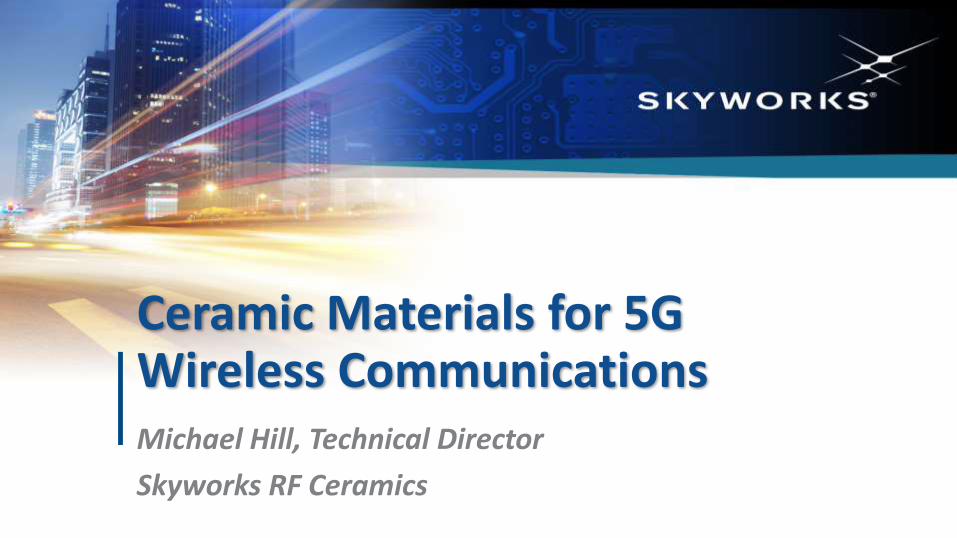
▪ 1G: Introduced ~ 1982 – Full Analog System
▪ 2G: Launched ~1991 – First Use of Digital Signals/GPRS and EDGE Technologies
▪ 3G: Launched ~2001 – Faster data rates
▪ 4G (LTE): 2011 – Current technology. Networks Strained by Content Demand (700 MHz – 2.7 GHz)
▪ 5G: (Est 2019 – Early 2020s)
– 3-5 GHz and mm-Wave (20-100 GHz)
– Higher Data Rates ~10 times faster than 4G
– Low Latency
• No Delays (Latency) Between Transmit and Receive Signals – i.e. autonomous vehicles
– Increased Connectivity
• Internet of Things (IoT); Increased capacity
Copyright © 2018 Skyworks Solutions, Inc.
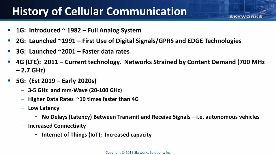
What are the Advantages of 5G?
Copyright © 2018 Skyworks Solutions, Inc.
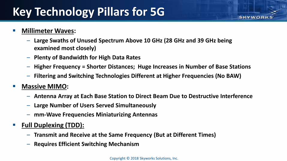
Key Technology Pillars for 5G
▪ Millimeter Waves:
– Large Swaths of Unused Spectrum Above 10 GHz (28 GHz and 39 GHz being examined most closely)
– Plenty of Bandwidth for High Data Rates
– Higher Frequency = Shorter Distances; Huge Increases in Number of Base Stations
– Filtering and Switching Technologies Different at Higher Frequencies (No BAW)
▪ Massive MIMO:
– Antenna Array at Each Base Station to Direct Beam Due to Destructive Interference
– Large Number of Users Served Simultaneously
– mm-Wave Frequencies Miniaturizing Antennas
▪ Full Duplexing (TDD):
– Transmit and Receive at the Same Frequency (But at Different Times)
– Requires Efficient Switching Mechanism
Copyright © 2018 Skyworks Solutions, Inc.
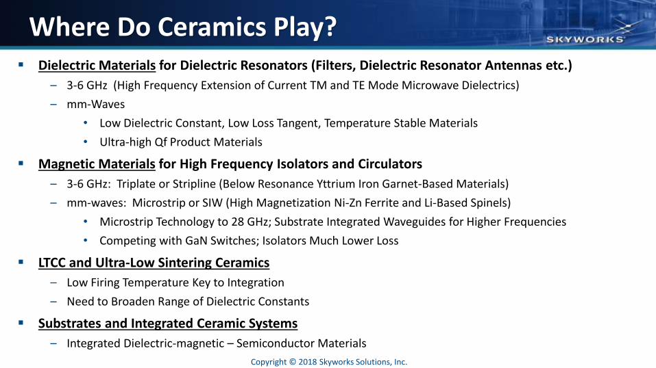
Where Do Ceramics Play?▪ Dielectric Materials for Dielectric Resonators (Filters, Dielectric Resonator Antennas etc.)
– 3-6 GHz (High Frequency Extension of Current TM and TE Mode Microwave Dielectrics)
– mm-Waves
• Low Dielectric Constant, Low Loss Tangent, Temperature Stable Materials
• Ultra-high Qf Product Materials
▪ Magnetic Materials for High Frequency Isolators and Circulators
– 3-6 GHz: Triplate or Stripline (Below Resonance Yttrium Iron Garnet-Based Materials)
– mm-waves: Microstrip or SIW (High Magnetization Ni-Zn Ferrite and Li-Based Spinels)
• Microstrip Technology to 28 GHz; Substrate Integrated Waveguides for Higher Frequencies
• Competing with GaN Switches; Isolators Much Lower Loss
▪ LTCC and Ultra-Low Sintering Ceramics
– Low Firing Temperature Key to Integration
– Need to Broaden Range of Dielectric Constants
▪ Substrates and Integrated Ceramic Systems
– Integrated Dielectric-magnetic – Semiconductor Materials
Copyright © 2018 Skyworks Solutions, Inc.
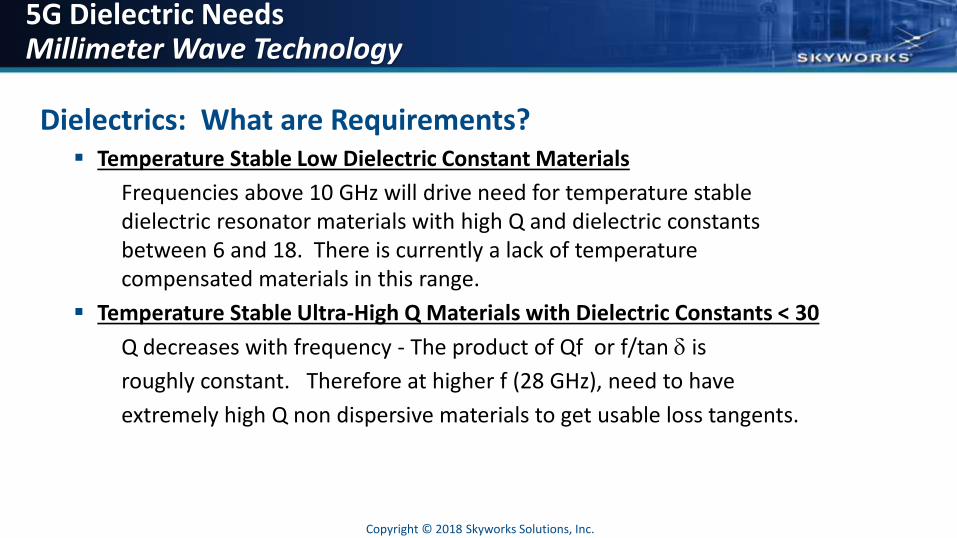
5G Dielectric Needs Millimeter Wave Technology
Dielectrics: What are Requirements?▪ Temperature Stable Low Dielectric Constant Materials
Frequencies above 10 GHz will drive need for temperature stable dielectric resonator materials with high Q and dielectric constants between 6 and 18. There is currently a lack of temperature compensated materials in this range.
▪ Temperature Stable Ultra-High Q Materials with Dielectric Constants < 30
Q decreases with frequency - The product of Qf or f/tan d is
roughly constant. Therefore at higher f (28 GHz), need to have
extremely high Q non dispersive materials to get usable loss tangents.
Copyright © 2018 Skyworks Solutions, Inc.
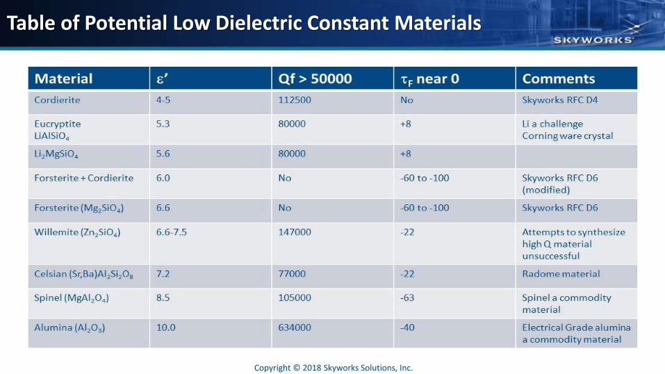
Table of Potential Low Dielectric Constant Materials
Copyright © 2018 Skyworks Solutions, Inc.
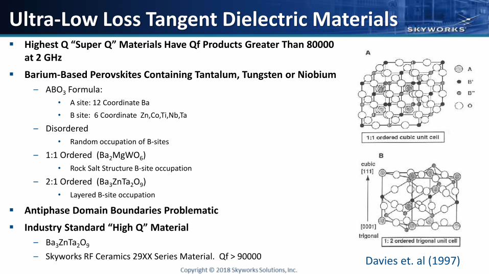
Ultra-Low Loss Tangent Dielectric Materials▪ Highest Q “Super Q” Materials Have Qf Products Greater Than 80000
at 2 GHz
▪ Barium-Based Perovskites Containing Tantalum, Tungsten or Niobium
– ABO3 Formula:
• A site: 12 Coordinate Ba
• B site: 6 Coordinate Zn,Co,Ti,Nb,Ta
– Disordered
• Random occupation of B-sites
– 1:1 Ordered (Ba2MgWO6)
• Rock Salt Structure B-site occupation
– 2:1 Ordered (Ba3ZnTa2O9)
• Layered B-site occupation
▪ Antiphase Domain Boundaries Problematic
▪ Industry Standard “High Q” Material
– Ba3ZnTa2O9
– Skyworks RF Ceramics 29XX Series Material. Qf > 90000 Davies et. al (1997)
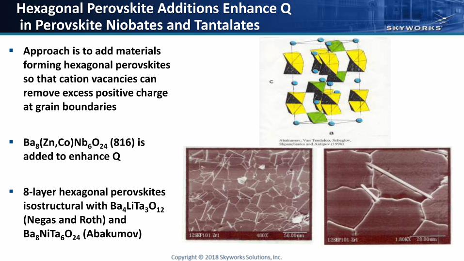
Hexagonal Perovskite Additions Enhance Qin Perovskite Niobates and Tantalates
▪ Approach is to add materials forming hexagonal perovskites so that cation vacancies can remove excess positive charge at grain boundaries
▪ Ba8(Zn,Co)Nb6O24 (816) is added to enhance Q
▪ 8-layer hexagonal perovskites isostructural with Ba4LiTa3O12
(Negas and Roth) and Ba8NiTa6O24 (Abakumov)
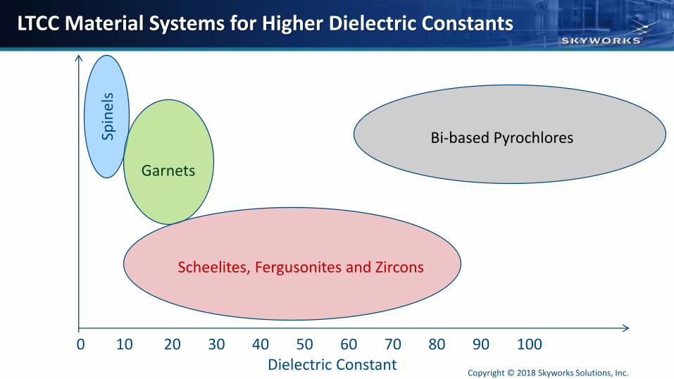
LTCC Material Systems for Higher Dielectric Constants
Dielectric Constant0 10 20 30 40 50 60 70 80 90 100
Spin
els
Garnets
Scheelites, Fergusonites and Zircons
Bi-based Pyrochlores
Copyright © 2018 Skyworks Solutions, Inc.
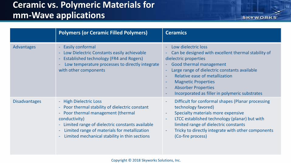
Ceramic vs. Polymeric Materials for mm-Wave applications
Polymers (or Ceramic Filled Polymers) Ceramics
Advantages - Easily conformal- Low Dielectric Constants easily achievable- Established technology (FR4 and Rogers)- Low temperature processes to directly integrate with other components
- Low dielectric loss- Can be designed with excellent thermal stability of dielectric properties- Good thermal management- Large range of dielectric constants available- Relative ease of metallization- Magnetic Properties- Absorber Properties- Incorporated as filler in polymeric substrates
Disadvantages - High Dielectric Loss- Poor thermal stability of dielectric constant- Poor thermal management (thermal conductivity)- Limited range of dielectric constants available- Limited range of materials for metallization- Limited mechanical stability in thin sections
- Difficult for conformal shapes (Planar processing technology favored)
- Specialty materials more expensive- LTCC established technology (planar) but with
limited range of dielectric constants- Tricky to directly integrate with other components
(Co-fire process)
Copyright © 2018 Skyworks Solutions, Inc.
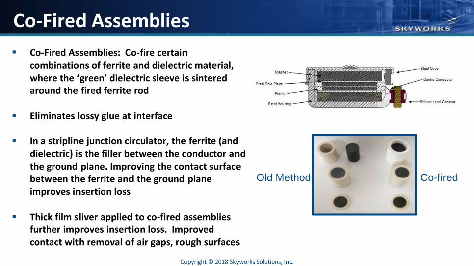
Co-Fired Assemblies
▪ Co-Fired Assemblies: Co-fire certain combinations of ferrite and dielectric material, where the ‘green’ dielectric sleeve is sintered around the fired ferrite rod
▪ Eliminates lossy glue at interface
▪ In a stripline junction circulator, the ferrite (and dielectric) is the filler between the conductor and the ground plane. Improving the contact surface between the ferrite and the ground plane improves insertion loss
▪ Thick film sliver applied to co-fired assemblies further improves insertion loss. Improved contact with removal of air gaps, rough surfaces
Old Method Co-fired
Copyright © 2018 Skyworks Solutions, Inc.
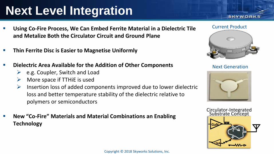
Next Level Integration
▪ Using Co-Fire Process, We Can Embed Ferrite Material in a Dielectric Tile and Metalize Both the Circulator Circuit and Ground Plane
▪ Thin Ferrite Disc is Easier to Magnetise Uniformly
▪ Dielectric Area Available for the Addition of Other Components➢ e.g. Coupler, Switch and Load➢ More space if TTHiE is used➢ Insertion loss of added components improved due to lower dielectric
loss and better temperature stability of the dielectric relative to polymers or semiconductors
▪ New “Co-Fire” Materials and Material Combinations an Enabling Technology
Current Product
Next Generation
GaN
LNA
Circulator-Integrated Substrate Concept
Copyright © 2018 Skyworks Solutions, Inc.
Conclusions
▪ 5G Systems Expected to be Deployed by ~2020
– Technology Still Needs to be Determined
– Dielectric Materials Should be Key Ceramic Materials for 5G
– Low Dielectric Constant Materials
– Ultra-Low Loss Tangent Materials
– LTCC Type Materials for Co-Firing; Low Temperature Firing Ceramics will be Enabling Technology
▪ Technology “Battles” Need to be Resolved
– Isolators vs. GaN Switches
– LTCC (Ceramic) vs. Polymer for Substrates, MIMO Antennas
– Ferrite based circulator vs. semiconductor based circulator for full duplexing
Copyright © 2018 Skyworks Solutions, Inc.