Embed Size (px)
Citation preview
1
Certa-set main line Piping system
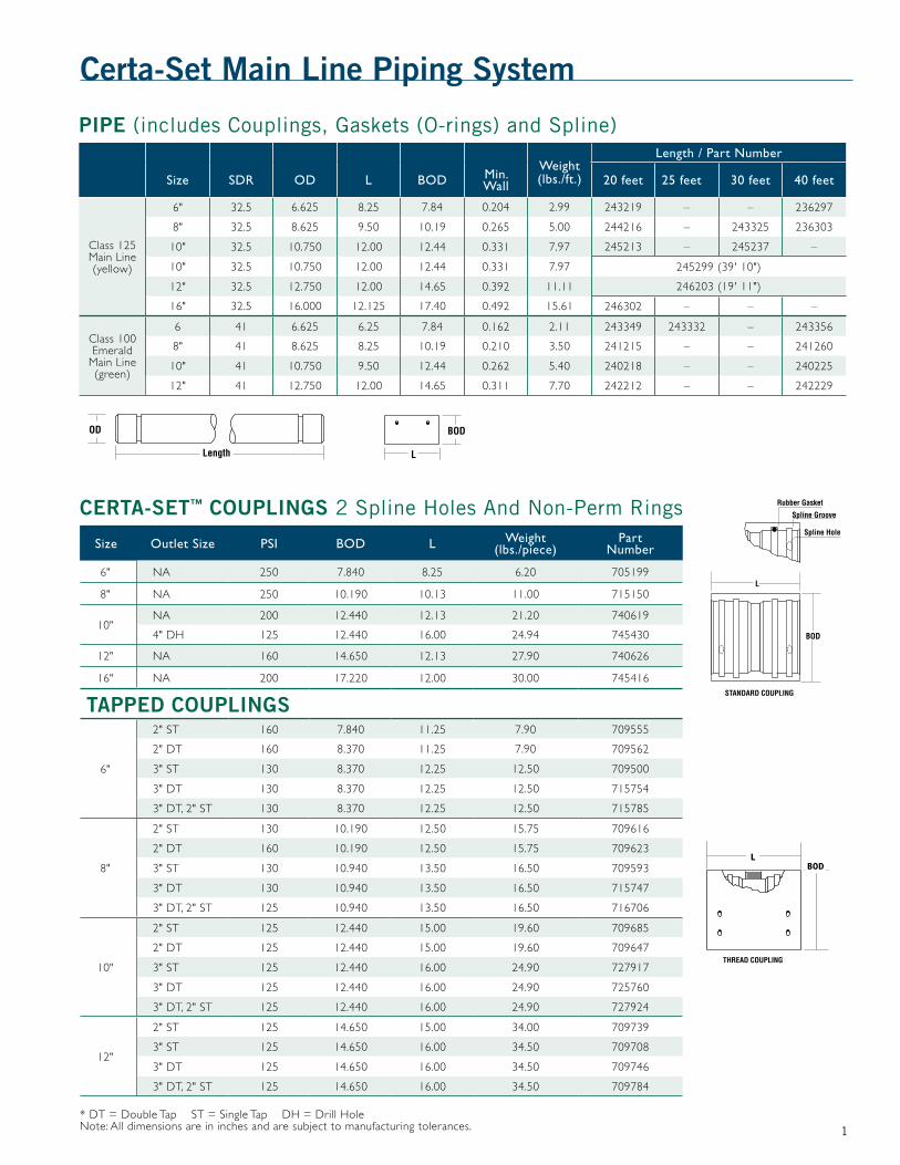
PiPe (includes Couplings, Gaskets (O-rings) and Spline)
Weight (lbs./ft.)
Length / Part Number
Size SDR OD L BOD Min. Wall 20 feet 25 feet 30 feet 40 feet
Class 125 Main Line (yellow)
6" 32.5 6.625 8.25 7.84 0.204 2.99 243219 – – 236297
8" 32.5 8.625 9.50 10.19 0.265 5.00 244216 – 243325 236303
10" 32.5 10.750 12.00 12.44 0.331 7.97 245213 – 245237 –
10" 32.5 10.750 12.00 12.44 0.331 7.97 245299 (39' 10")
12" 32.5 12.750 12.00 14.65 0.392 11.11 246203 (19' 11")
16" 32.5 16.000 12.125 17.40 0.492 15.61 246302 – – –
Class 100 Emerald
Main Line (green)
6 41 6.625 6.25 7.84 0.162 2.11 243349 243332 – 243356
8" 41 8.625 8.25 10.19 0.210 3.50 241215 – – 241260
10" 41 10.750 9.50 12.44 0.262 5.40 240218 – – 240225
12" 41 12.750 12.00 14.65 0.311 7.70 242212 – – 242229
BODL
CertA-set™ CouPlinGs 2 Spline Holes And Non-Perm Rings
Size Outlet Size PSI BOD L Weight (lbs./piece)
Part Number
6" NA 250 7.840 8.25 6.20 705199
8" NA 250 10.190 10.13 11.00 715150
10"NA 200 12.440 12.13 21.20 740619
4" DH 125 12.440 16.00 24.94 745430
12" NA 160 14.650 12.13 27.90 740626
16" NA 200 17.220 12.00 30.00 745416
tAPPed CouPlinGs
6"
2" ST 160 7.840 11.25 7.90 709555
2" DT 160 8.370 11.25 7.90 709562
3" ST 130 8.370 12.25 12.50 709500
3" DT 130 8.370 12.25 12.50 715754
3" DT, 2" ST 130 8.370 12.25 12.50 715785
8"
2" ST 130 10.190 12.50 15.75 709616
2" DT 160 10.190 12.50 15.75 709623
3" ST 130 10.940 13.50 16.50 709593
3" DT 130 10.940 13.50 16.50 715747
3" DT, 2" ST 125 10.940 13.50 16.50 716706
10"
2" ST 125 12.440 15.00 19.60 709685
2" DT 125 12.440 15.00 19.60 709647
3" ST 125 12.440 16.00 24.90 727917
3" DT 125 12.440 16.00 24.90 725760
3" DT, 2" ST 125 12.440 16.00 24.90 727924
12"
2" ST 125 14.650 15.00 34.00 709739
3" ST 125 14.650 16.00 34.50 709708
3" DT 125 14.650 16.00 34.50 709746
3" DT, 2" ST 125 14.650 16.00 34.50 709784
* DT = Double Tap ST = Single Tap DH = Drill Hole Note: All dimensions are in inches and are subject to manufacturing tolerances.

2
Certa-set main line Fittings iPs
Flange adapters
Weight (lbs./piece)
L
Bolt Circle
Description Size PSI OD1 OD2 R. Dia. A. No. Holes
Part Number
Main Line 6" 150 9.00 6.625 11.000 1.281 12.44 9.50 8 705779
Main Line 8" 150 16.00 8.625 13.500 1.375 13.38 11.75 8 705786
Main Line 10" 150 25.40 10.75 16.000 1.625 16.69 14.25 12 707773
Main Line 12" 150 36.70 12.75 19.000 1.500 16.63 17.00 12 745539
nipples Male x Male Pipe ThreadsDescription Size PSI Weight (lbs./piece) OD L Part Number
Main Line 3" 125 1.06 3.500 6.00 706790
Main Line 6" 140 5.20 6.625 12.00 706028
Main Line 8" 120 9.00 8.625 13.00 706035
nipples Male x Plain EndDescription Size PSI Weight (lbs./piece) OD L Part Number
Main Line 6" 250 5.20 6.625 12.00 705878
Main Line 8" 250 9.70 8.625 13.00 705885
Main Line 10" 200 11.10 10.750 16.00 706325
Main Line 12" 125 15.50 12.750 16.00 706332
teesDescription Size PSI Weight (lbs./piece) OD L Part Number
Main Line 6" 250 25.00 6.625 31.00 704635
Main Line 8" 250 48.00 8.625 36.25 704642
Main Line 10" 200 81.52 10.750 45.38 704581
Main Line 12" 160 125.63 12.750 45.00 745522
elbowsDescription Size PSI Weight (lbs./piece) OD L Part Number
Main Line (90º) 6" 250 17.40 6.625 15.63 704895
Main Line (90º) 8" 250 33.70 8.625 18.00 704901
Main Line (90º) 10" 200 59.66 10.750 26.75 704765
Main Line (90º/45º) 12" 125 99.28 12.750 28.75 745515

3
Certa-set main line Fittings iPs (continued)
spline insertion tools*
Description Size Weight (lbs./piece) Part Number
Main Line 6" 2.25 707964
Main Line 8" - 12" 2.25 707971
* Only for assembly
o-rings
Description Size C/S Material OD Part Number
Main Line 6" 0.275 NBR 7.176 861277
Main Line 8" 0.375 IR 9.350 862717
Main Line 10" 0.407 IR 11.500 861697
Main Line 12" 0.407 IR 13.500 861703
splinesDescription Size Length C/S Config. Part
Number
Main Line 6" 24 0.250 Round 864636
Main Line 8" 32 0.313 Square 864643
Main Line 10" 39 0.313 Square 864872
Main Line 12" 46 0.313 Square 864896
Note: All dimensions are in inches and are subject to manufacturing tolerances.
OD
end CapsSize PSI Weight (lbs./piece) OD Length Part Number
6" 250 9.00 7.8400 9.00 700019
8" 250 17.00 10.190 10.13 700026
10" 200 22.00 12.440 12.13 700033
12" 200 28.00 14.650 12.13 745508

4
Certa-set spline insertion tools*Description Size Weight (lbs./piece) Part Number
Certa-Set 3" 3.00 707988
* Only for assembly
CertA-set sled ComPonents – o-rinGsDescription Size Material Part Number
Certa-Set Sled 1/2" NBR 862564
Certa-Set Coupling 3" NBR 862502
Certa-Set 3/4" Cap 3/4" NA 862526
CertA-set sled ComPonents – sPlinesDescription Size Length C/S Config. Part Number
Certa-Set 3" 12" NA Serrated 864599
Certa-set™ lateral Piping system
riser PiPe stoCk (20-Foot Length)Size Pressure Class OD Min. Wall Weight (lbs./ft.) Length
(Feet) Part Number
1/2" SCH80 0.840 0.147 0.21 20 0500083/4" SCH80 1.050 0.154 0.28 20 050015
lateral sprinkler pipe
SizePressure Rating,
psiOD L BOD Weight (lbs./
ft.)Length / Part Number
15 feet 19 feet 20 feet 30 feet 40 feet
3" 125 3.00 7.5 3.625 0.80 001529 252204 252211 252310 252419
Certa-set sled Components – riser Cap and Coupling sled
Description Configuration Pressure Rating, psi L Width Weight
(lbs./piece) BOD Part Number
Riser Cap 1/2" Dual Hook Riser Cap 125 NA NA 0.05 NA 700491
Riser Cap 1/2" Single Hook Riser Cap 125 NA NA 0.10 NA 700361
Riser Cap 3/4" Riser Cap 125 NA NA 0.13 NA 700347
Kit - Sled Kit - Sled Coupler Kit (Coupler, 2 Splines, 2 O-rings) 125 7.50 6.00 1.40 3.625 700606
Kit - Cap Kit - 1/2" Cap (Single Hook Cap and Gasket) 125 NA NA 0.10 NA 700613
Kit - Cap Kit - 3/4" Cap (Cap and Gasket) 125 NA NA 0.16 NA 700620
Kit - Cap Kit - 1/2" Cap (Double Hook Cap and Gasket) 125 NA NA 0.16 NA 700637
1/2" CAP Single Hook
3/4" CAP

5
CertA-set ACCessory FittinGsDescription Configuration PSI Length OD Weight
(lbs./piece) Part Number
Adapter Nipple 3" Cer ta-Set Male x 3" IPS Plain End 125 6.50 3.00 1.95 700392
Adapter Nipple 3" Cer ta-Set Male x 3" IPS MIPT 125 5.00 3.00 0.63 745652
Nipple 3" Cer ta-Set Male x 3" Cer ta-Set Male 125 5.75 3.00 0.70 745737
Nipple 3" Cer ta-Set Female x 3" IPS MIPT 125 3.75 3.50 0.67 745669
Nipple3" Cer ta-Set
Female x 3" IPS Plain End
125 3.75 3.00 0.80 715907
Nipple (Lateral)
3" Cer ta-Set Male x 3" Cer ta-Set
Plain End125 6.50 3.00 0.50 700385
End Plug Sled Coupling End Plug 125 4.00 3.00 0.94 745607
Coupling 3" Cer ta-Set Female x 3" Cer ta-Set Female 125 5.25 3.50 0.65 715204
Certa-set lateral Fittings

6
Description Configuration PSI Length OD Weight (lbs./piece) Part Number
Coupling Cer ta-Set Solvent Weld Coupling 125 6.00 3.00 0.45 715969
Flange 3" Cer ta-Set Female x Flange 125 3.00 3.00 3.10 715952
Tee (Lateral) 3" Certa-Set Female Tee 125 3.00 3.50 4.50 745720
Elbow (90º Lateral)
3" Certa-Set 90º Female Elbow 125 3.75 3.50 3.00 700378
Adapter
3" Cer ta-Set Male x 2-1/2"
Solvent Weld Bell Adapter
125 6.25 3.00 0.60 715921
Pipe Repair Fitting
3" Cer ta-Set Male x Solvent Weld
Repair end125 12.00 3.00 0.90 715877
Certa-set lateral Fittings (continued)

7
Packaging and Weights
Size Type Lay Length
Pressure Rating,
psi
Approx. Weight (lbs./ft.)
Feet Per Fast-Pak
Approx. Weight Lbs./
Fast-Pak
Fast- Paks Per
Truck Load
Feet Per Truck Load
Fast-Pak % of Truck
LoadPart
Number
1/2" Certa-Set Riser Stock 20 850 0.21 8,000 1,672 28 224,000 3.57 0500083/4" Certa-Set Riser Stock 20 690 0.28 8,000 2,256 21 168,000 4.76 050015
3" Cer ta-Set
15
125 0.80
870 696 32 27,840 3.13 001529
20 1,160 928 28 32,480 3.57 252211
30 1,740 1,392 14 24,360 7.14 252310
40 2,320 1,856 14 32,480 7.14 252419
3" Kwik-Latch 30 125 0.80 1,740 1,392 16 27,840 6.25 252327
6" Cer ta-Lok Class 125 Main Line
20125 2.99
400 1,196 20 8,000 5.00 243219
40 800 2,392 10 8,000 10.00 236297
8"
Cer ta-Lok Class 125 Main Line
20
125 5.00
280 1,400 16 4,480 6.25 244216
30 420 2,100 8 3,360 12.50 243325
40 560 1,674 8 4,480 12.50 236303
Certa-Lok Class 100 Main Line
20100 3.50
280 980 16 4,480 6.25 241215
40 560 1,960 8 4,480 12.50 241260
10"
Cer ta-Lok Class 125 Main Line
20
125 7.97
160 1,275 18 2,880 5.56 245213
30 240 1,913 9 2,160 11.11 245237
40 320 2,550 9 2,880 11.11 245220
Certa-Lok Class 100 Main Line
20100 5.40
160 864 18 2,880 5.56 240218
40 230 1,728 9 2,880 11.11 240225
12"
Cer ta-Lok Class 125 Main Line 20 125 11.11 160/80 1,777/889 12/4* 2,240 7.14/3.75 246210
Certa-Lok Class 100 Main Line 20 100 7.70 160/80 1,232/616 12/4* 2,240 7.14/3.75 242212
16" Cer ta-Lok Class 125 Main Line 20 125 15.61 120 1,873 12 1,440 8.33 246302
CertainTeed offers a seven-year limited warranty on 3" Certa-Set pipe and couplings (see CertainTeed document number 40-90-47). Please note the following pertinent application limitations:
1. Certa-Set lateral piping has been designed for drag applications where the tensile pull must not exceed 3,500 lbs. Exceeding 3,500 lbs. pull will stress the pipe at the spline groove, resulting in spline override and possible premature pipe or coupling breakage.
2. All risers must be removed from the couplings prior to drag movement in heavy foliage installations, in as much as under certain crop conditions, foliage can become entangled with the risers, resulting in excessive deflection (stress) on the coupling boss during movement. Any excessive deflection can result in possible breakage at the coupling boss.
3. Water needs to be drained from the 3" lateral pipe before drag or mechanical retrieval. Failure to do so will result in spline override, with resulting coupling damage. Also, failure to drain water in drag applications will cause severe abrasion
to the sled coupling and pipe over time. To remove water, simply remove the Certa-Set end plug (CertainTeed Part No. 745607) and allow the water to drain. It is not required to drain the water when performing a lateral mechanical shift of up to 20 feet.
4. During mechanized lateral movement of the 3" Certa-Set pipe, pipe offset must not exceed 40 inches per 20 feet of pipe. Exceeding this level will place excessive stress on the sled coupling at the spline groove, resulting in premature coupling breakage.
5. CAUTION – Under no circumstances should any farm implement (tractor, mower, etc.) be used to impact the coupling or pipe for the intended purpose of lateral or directional movement. Additionally, no farm implements are to be driven over the 3" lateral pipe.
6. CertainTeed will not assume any responsibility or liability for damage directly or indirectly resulting from the failure to serve the intended purpose of any component, such as saddles, which are used to modify CertainTeed’s standard products.
Important Certa-Set Application Limitations
8
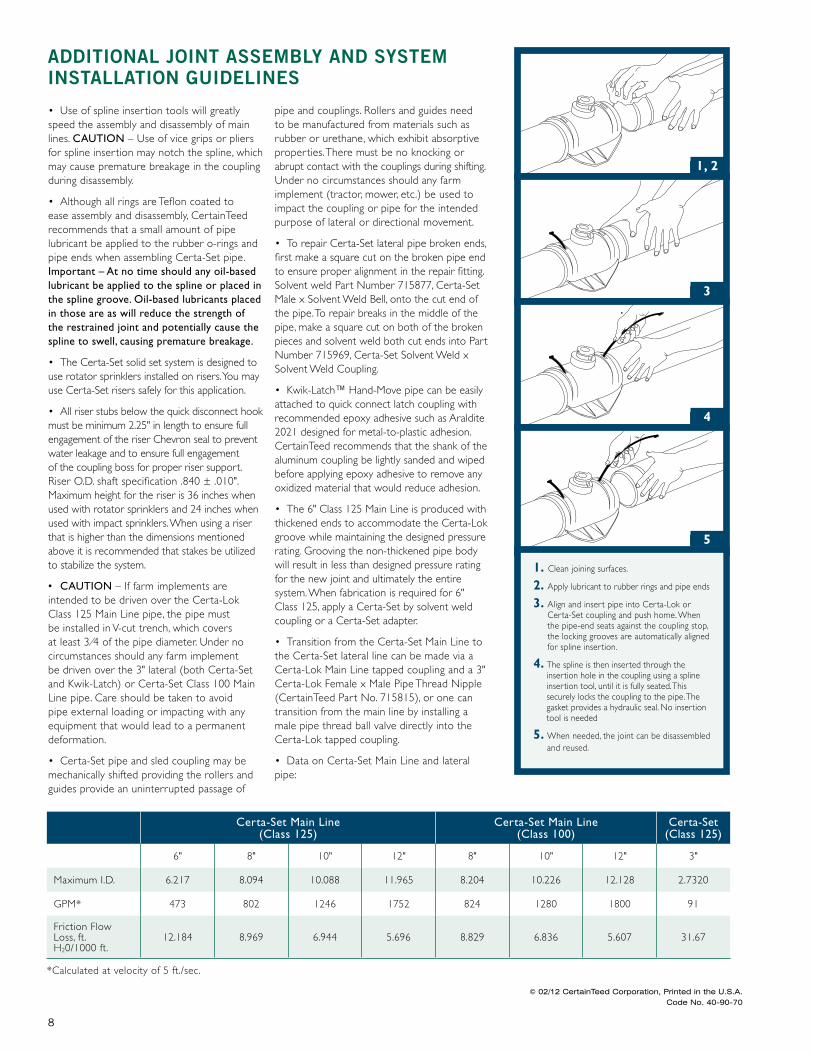
1. Clean joining surfaces.
2. Apply lubricant to rubber rings and pipe ends
3. Align and insert pipe into Certa-Lok or Certa-Set coupling and push home. When the pipe-end seats against the coupling stop, the locking grooves are automatically aligned for spline insertion.
4. The spline is then inserted through the insertion hole in the coupling using a spline insertion tool, until it is fully seated. This securely locks the coupling to the pipe. The gasket provides a hydraulic seal. No insertion tool is needed
5. When needed, the joint can be disassembled and reused.
1, 2
3
4
5
• Use of spline insertion tools will greatly speed the assembly and disassembly of main lines. CAUTION – Use of vice grips or pliers for spline insertion may notch the spline, which may cause premature breakage in the coupling during disassembly.
• Although all rings are Teflon coated to ease assembly and disassembly, CertainTeed recommends that a small amount of pipe lubricant be applied to the rubber o-rings and pipe ends when assembling Certa-Set pipe. Important – At no time should any oil-based lubricant be applied to the spline or placed in the spline groove. Oil-based lubricants placed in those are as will reduce the strength of the restrained joint and potentially cause the spline to swell, causing premature breakage.
• The Certa-Set solid set system is designed to use rotator sprinklers installed on risers. You may use Certa-Set risers safely for this application.
• All riser stubs below the quick disconnect hook must be minimum 2.25" in length to ensure full engagement of the riser Chevron seal to prevent water leakage and to ensure full engagement of the coupling boss for proper riser support. Riser O.D. shaft specification .840 ± .010". Maximum height for the riser is 36 inches when used with rotator sprinklers and 24 inches when used with impact sprinklers. When using a riser that is higher than the dimensions mentioned above it is recommended that stakes be utilized to stabilize the system.
• CAUTION – If farm implements are intended to be driven over the Certa-Lok Class 125 Main Line pipe, the pipe must be installed in V-cut trench, which covers at least 3 ⁄4 of the pipe diameter. Under no circumstances should any farm implement be driven over the 3" lateral (both Certa-Set and Kwik-Latch) or Certa-Set Class 100 Main Line pipe. Care should be taken to avoid pipe external loading or impacting with any equipment that would lead to a permanent deformation.
• Certa-Set pipe and sled coupling may be mechanically shifted providing the rollers and guides provide an uninterrupted passage of
pipe and couplings. Rollers and guides need to be manufactured from materials such as rubber or urethane, which exhibit absorptive properties. There must be no knocking or abrupt contact with the couplings during shifting. Under no circumstances should any farm implement (tractor, mower, etc.) be used to impact the coupling or pipe for the intended purpose of lateral or directional movement.
• To repair Certa-Set lateral pipe broken ends, first make a square cut on the broken pipe end to ensure proper alignment in the repair fitting. Solvent weld Part Number 715877, Certa-Set Male x Solvent Weld Bell, onto the cut end of the pipe. To repair breaks in the middle of the pipe, make a square cut on both of the broken pieces and solvent weld both cut ends into Part Number 715969, Certa-Set Solvent Weld x Solvent Weld Coupling.
• Kwik-Latch™ Hand-Move pipe can be easily attached to quick connect latch coupling with recommended epoxy adhesive such as Araldite 2021 designed for metal-to-plastic adhesion. CertainTeed recommends that the shank of the aluminum coupling be lightly sanded and wiped before applying epoxy adhesive to remove any oxidized material that would reduce adhesion.
• The 6" Class 125 Main Line is produced with thickened ends to accommodate the Certa-Lok groove while maintaining the designed pressure rating. Grooving the non-thickened pipe body will result in less than designed pressure rating for the new joint and ultimately the entire system. When fabrication is required for 6" Class 125, apply a Certa-Set by solvent weld coupling or a Certa-Set adapter.
• Transition from the Certa-Set Main Line to the Certa-Set lateral line can be made via a Certa-Lok Main Line tapped coupling and a 3" Certa-Lok Female x Male Pipe Thread Nipple (CertainTeed Part No. 715815), or one can transition from the main line by installing a male pipe thread ball valve directly into the Certa-Lok tapped coupling.
• Data on Certa-Set Main Line and lateral pipe:
AdditionAl Joint Assembly And system instAllAtion Guidelines
Certa-Set Main Line (Class 125)
Certa-Set Main Line (Class 100)
Certa-Set (Class 125)
6" 8" 10" 12" 8" 10" 12" 3"
Maximum I.D. 6.217 8.094 10.088 11.965 8.204 10.226 12.128 2.7320
GPM* 473 802 1246 1752 824 1280 1800 91
Friction Flow Loss, ft. H20/1000 ft.
12.184 8.969 6.944 5.696 8.829 6.836 5.607 31.67
*Calculated at velocity of 5 ft./sec.
© 02/12 CertainTeed Corporation, Printed in the U.S.A. Code No. 40-90-70