Embed Size (px)
Citation preview
FF0 002
DQD 507 Rev. 2012-05-22 Page 1
Certificate of Compliance Certificate: 2708406 Master Contract: 259813
Project: 2722409 Date Issued: April 24, 2014
Issued to: ABB, Inc.
16250 W. Glendale Drive
New Berlin, WI 53151
USA
The products listed below are eligible to bear the CSA Mark shown with
adjacent indicators 'C' and 'US' for Canada and US or with adjacent
indicator 'US' for US only or without either indicator for Canada only.
Issued by: Jocelyn Jens
Product Group Coordinator
Authorized by:
Lindsay Clark
Operations Manager
PRODUCTS
CLASS 5311 09 - POWER SUPPLIES - Distributed Generation Power Systems Equipment
CLASS 5311 89 - POWER SUPPLIES - Distributed Generation - Power Systems Equipment
- Certified to U.S. Standards
Utility Interactive Inverter, Models PVI-4.2-OUTD-US, PVI-3.8-OUTD-US, PVI-3.6-OUTD-US,
PVI-3.0-OUTD-US, PVI-4.2-OUTD-S-US, PVI-3.8-OUTD-S-US, PVI-3.6-OUTD-S-US, PVI-3.0-OUTD-S-US,
PVI-4.2-OUTD-S-US-A, PVI-3.8-OUTD-S-US-A, PVI-3.6-OUTD-S-US-A, PVI-3.0-OUTD-S-US-A,
PVI-4.2-OUTD-US-W, PVI-3.8-OUTD-US-W, PVI-3.6-OUTD-US-W and PVI-3.0-OUTD-US-W; provided
with two DC input channels, permanently connected, system ratings as follows:
Notes:
1. All above models in this series may include expansion board with wireless antennae option and will be
identified with model designation including “–Z” suffix.
2. For details related to rating, size, configuration, etc. reference should be made to the CSA Certification
Record or the Certificate of Compliance Annex A.
Certificate: 2708406
Project: 2722409
Master Contract: 259813
Date Issued: April 24, 2014
DQD 507 Rev. 2012-05-22 Page 2
APPLICABLE REQUIREMENTS
CSA-C22.2 No.107.1-01 - General Use Power Supplies
*UL Std No. 1741-Second Edition - Inverters, Converters, Controllers and Interconnection System
Equipment for Use With Distributed Energy Resources
(January 28, 2010)
UL 1699B - Outline of Investigation for Photovoltaic (PV) DC Arc-Fault Circuit
Protection (Issue Number 2, January 14, 2013)
CSA TIL M-07 Interim Certification Requirements for Photovoltaic (PV) DC Arc Fault
Protection (Issue Number 1, March 11, 2013)
*Note: Conformity to UL 1741-Second Edition (January 28, 2010) includes compliance with applicable
requirements of IEEE 1547 and IEEE 1547.1

DQD 507 Rev. 2012-05-22 Page 1
Supplement to Certificate of Compliance
Certificate: 2708406 (Project 2722409) Master Contract: 259813
The products listed, including the latest revision described below,
are eligible to be marked in accordance with the referenced Certificate.
Product Certification History
Project Date Description
2708406 March 12, 2014 Multiple Listing for Power-One / ABB, Models PVI-4.2-OUTD-US,
PVI-3.8-OUTD-US, PVI-3.6-OUTD-US, PVI-3.0-OUTD-US,
PVI-4.2-OUTD-S-US, PVI-3.8-OUTD-S-US, PVI-3.6-OUTD-S-US,
PVI-3.0-OUTD-S-US, PVI-4.2-OUTD-S-US-A, PVI-3.8-OUTD-S-US-A,
PVI-3.6-OUTD-S-US-A, PVI-3.0-OUTD-S-US-A, PVI-4.2-OUTD-US-W,
PVI-3.8-OUTD-US-W, PVI-3.6-OUTD-US-W, PVI-3.0-OUTD-US-W
(Alt. File No. 259813, Form A)
2722409 April 24, 2014 Update ML Certificate to include firmware changes.
Multiple Listing
Project No
Listee
Models
Submittor
Models
Submittor
Project No
2708406 PVI-4.2-OUTD-US PVI-4.2-OUTD-US 2096477 (2682842)
2708406 PVI-3.8-OUTD-US PVI-3.8-OUTD-US 2096477 (2682842)
2708406 PVI-3.6-OUTD-US PVI-3.6-OUTD-US 2096477 (2682842)
2708406 PVI-3.0-OUTD-US PVI-3.0-OUTD-US 2096477 (2682842)
2708406 PVI-4.2-OUTD-S-US PVI-4.2-OUTD-S-US 2096477 (2682842)
2708406 PVI-3.8-OUTD-S-US PVI-3.8-OUTD-S-US 2096477 (2682842)
2708406 PVI-3.6-OUTD-S-US PVI-3.6-OUTD-S-US 2096477 (2682842)
2708406 PVI-3.0-OUTD-S-US PVI-3.0-OUTD-S-US 2096477 (2682842)
2708406 PVI-4.2-OUTD-S-US-A PVI-4.2-OUTD-S-US-A 2096477 (2682842)
2708406 PVI-3.8-OUTD-S-US-A PVI-3.8-OUTD-S-US-A 2096477 (2682842)
2708406 PVI-3.6-OUTD-S-US-A PVI-3.6-OUTD-S-US-A 2096477 (2682842)
2708406 PVI-3.0-OUTD-S-US-A PVI-3.0-OUTD-S-US-A 2096477 (2682842)
2708406 PVI-4.2-OUTD-US-W PVI-4.2-OUTD-US-W 2096477 (2682842)
2708406 PVI-3.8-OUTD-US-W PVI-3.8-OUTD-US-W 2096477 (2682842)
2708406 PVI-3.6-OUTD-US-W PVI-3.6-OUTD-US-W 2096477 (2682842)
2708406 PVI-3.0-OUTD-US-W PVI-3.0-OUTD-US-W 2096477 (2682842)

Page 1 of 17 CSA Ref. No. 259813-2708406 (2722409)
Certificate of Compliance Annex A
PVI-4.2(3.8)(3.6)(3.0)-OUTD-US (cCSAus Multiple Listing Certificate, Annex A, Ref. 259813-2708406, Project 2722409) Rev. 2014-04-24\1\kf
Utility Interactive Inverter, Models PVI-4.2-OUTD-US, PVI-3.8-OUTD-US, PVI-3.6-OUTD-US, PVI-3.0-OUTD-US, PVI-4.2-OUTD-S-US, PVI-3.8-OUTD-S-US, PVI-3.6-OUTD-S-US, PVI-3.0-OUTD-S-US, PVI-4.2-OUTD-S-US-A, PVI-3.8-OUTD-S-US-A, PVI-3.6-OUTD-S-US-A, PVI-3.0-OUTD-S-US-A, PVI-4.2-OUTD-US-W, PVI-3.8-OUTD-US-W, PVI-3.6-OUTD-US-W and PVI-3.0-OUTD-US-W; provided with two DC input channels, permanently connected, system ratings as follows: PART A: Utility Interactive Inverter, Models PVI-4.2-OUTD-US, PVI-4.2-OUTD-S-US, PVI-4.2-OUTD-S-US-A, and PVI-4.2-OUTD-US-W: Model PVI-4.2-OUTD-US PVI-4.2-OUTD-S-US &
PVI-4.2-OUTD-S-US-A PVI-4.2-OUTD-US-W
Maximum Input Voltage (DC)
600 V dc 600 V dc 600 V dc
Range of Input Operating Voltage (DC)
90-580 V dc, 360 V dc nominal
90-580 V dc, 360 V dc nominal
50-580 V dc, 360 V dc nominal
Maximum Input Current (DC)
16 A (Each Input - 2 provided)
16 A (Each Input - 2 provided)
32 A
Maximum Input Short Circuit Current (DC)
20 A (Each Input - 2 provided)
20 A (Each Input - 2 provided)
40 A
Maximum Utility Backfeed Current (AC)
0 A 0 A 0 A
Output Power Factor Rating >0.995 >0.995 >0.995 Operating Voltage Range (AC) (See Note 2)
244-304 V ac for 277 V ac configuration 211-264 V ac for 240 V ac configuration 183-228 V ac for 208 V ac configuration
244-304 V ac for 277 V ac configuration 211-264 V ac for 240 V ac configuration 183-228 V ac for 208 V ac configuration
244-304 V ac for 277 V ac configuration 211-264 V ac for 240 V ac configuration 183-228 V ac for 208 V ac configuration
Operating Frequency Range (HZ)
59.3-60.5 Hz (Default) 59.3-60.5 Hz (Default) 59.3-60.5 Hz (Default)
Field Adjustable Operating Frequency Range (HZ)
57.0-59.8 Hz, 60.2-63.0 Hz
57.0-59.8 Hz, 60.2-63.0 Hz
57.0-59.8 Hz, 60.2-63.0 Hz
Number of Phases 1 1 1 Nominal Output Voltage (AC) (See Note 2)
277 V ac / 240 V ac / 208 V ac
277 V ac / 240 V ac / 208 V ac
277 V ac / 240 V ac / 208 V ac
Normal Output Frequency 60 Hz 60 Hz 60 Hz Continuous Output Current (AC)
20 A / 20 A / 20 A 20 A / 20 A / 20 A 20 A / 20 A / 20 A
Maximum Output Power (AC) (See Note 4)
4600 W/ 4600 W / 4200 W
4600 W/ 4600 W / 4200 W
4600 W/ 4600 W / 4200 W
Maximum Continuous Output Power (AC) @ +45°C ambient (See Note 4)
4200 W 4200 W 4200 W
Maximum Output Fault Current and Duration
(See Note 6) (See Note 6) (See Note 6)
Maximum Output Overcurrent Protection
25 A / 25 A/ 25 A 25 A / 25 A/ 25 A 25 A / 25 A/ 25 A
Utility Interconnection and Voltage and Frequency Trip Limits and Trip Times
See Note 7 See Note 7 See Note 7
Page 2 of 17 CSA Ref. No. 259813-2708406 (2722409)
Certificate of Compliance Annex A
PVI-4.2(3.8)(3.6)(3.0)-OUTD-US (cCSAus Multiple Listing Certificate, Annex A, Ref. 259813-2708406, Project 2722409) Rev. 2014-04-24\2\kf
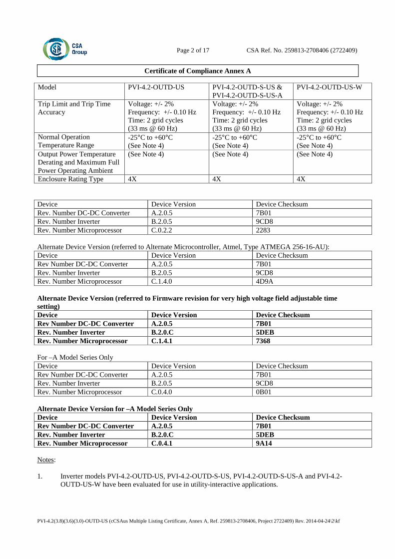
Model PVI-4.2-OUTD-US PVI-4.2-OUTD-S-US & PVI-4.2-OUTD-S-US-A
PVI-4.2-OUTD-US-W
Trip Limit and Trip Time Accuracy
Voltage: +/- 2% Frequency: +/- 0.10 Hz Time: 2 grid cycles (33 ms @ 60 Hz)
Voltage: +/- 2% Frequency: +/- 0.10 Hz Time: 2 grid cycles (33 ms @ 60 Hz)
Voltage: +/- 2% Frequency: +/- 0.10 Hz Time: 2 grid cycles (33 ms @ 60 Hz)
Normal Operation Temperature Range
-25°C to +60°C (See Note 4)
-25°C to +60°C (See Note 4)
-25°C to +60°C (See Note 4)
Output Power Temperature Derating and Maximum Full Power Operating Ambient
(See Note 4) (See Note 4) (See Note 4)
Enclosure Rating Type 4X 4X 4X Device Device Version Device Checksum Rev. Number DC-DC Converter A.2.0.5 7B01 Rev. Number Inverter B.2.0.5 9CD8 Rev. Number Microprocessor C.0.2.2 2283 Alternate Device Version (referred to Alternate Microcontroller, Atmel, Type ATMEGA 256-16-AU): Device Device Version Device Checksum Rev Number DC-DC Converter A.2.0.5 7B01 Rev. Number Inverter B.2.0.5 9CD8 Rev. Number Microprocessor C.1.4.0 4D9A Alternate Device Version (referred to Firmware revision for very high voltage field adjustable time setting) Device Device Version Device Checksum Rev Number DC-DC Converter A.2.0.5 7B01 Rev. Number Inverter B.2.0.C 5DEB Rev. Number Microprocessor C.1.4.1 7368 For –A Model Series Only Device Device Version Device Checksum Rev Number DC-DC Converter A.2.0.5 7B01 Rev. Number Inverter B.2.0.5 9CD8 Rev. Number Microprocessor C.0.4.0 0B01 Alternate Device Version for –A Model Series Only Device Device Version Device Checksum Rev Number DC-DC Converter A.2.0.5 7B01 Rev. Number Inverter B.2.0.C 5DEB Rev. Number Microprocessor C.0.4.1 9A14 Notes: 1. Inverter models PVI-4.2-OUTD-US, PVI-4.2-OUTD-S-US, PVI-4.2-OUTD-S-US-A and PVI-4.2-
OUTD-US-W have been evaluated for use in utility-interactive applications.
Page 3 of 17 CSA Ref. No. 259813-2708406 (2722409)
Certificate of Compliance Annex A
PVI-4.2(3.8)(3.6)(3.0)-OUTD-US (cCSAus Multiple Listing Certificate, Annex A, Ref. 259813-2708406, Project 2722409) Rev. 2014-04-24\3\kf
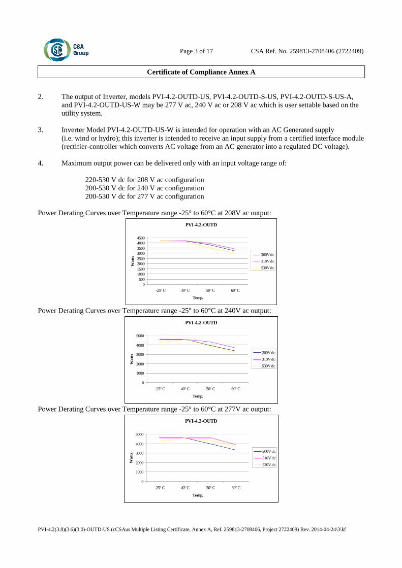
2. The output of Inverter, models PVI-4.2-OUTD-US, PVI-4.2-OUTD-S-US, PVI-4.2-OUTD-S-US-A,
and PVI-4.2-OUTD-US-W may be 277 V ac, 240 V ac or 208 V ac which is user settable based on the utility system.
3. Inverter Model PVI-4.2-OUTD-US-W is intended for operation with an AC Generated supply
(i.e. wind or hydro); this inverter is intended to receive an input supply from a certified interface module (rectifier-controller which converts AC voltage from an AC generator into a regulated DC voltage).
4. Maximum output power can be delivered only with an input voltage range of: 220-530 V dc for 208 V ac configuration 200-530 V dc for 240 V ac configuration 200-530 V dc for 277 V ac configuration Power Derating Curves over Temperature range -25° to 60°C at 208V ac output:
PVI-4.2-OUTD
0500
10001500200025003000350040004500
-25º C 40º C 50º C 60º C
Temp.
Wa
tts
200V dc
310V dc
530V dc
Power Derating Curves over Temperature range -25° to 60°C at 240V ac output:
PVI-4.2-OUTD
0
1000
2000
3000
4000
5000
-25º C 40º C 50º C 60º C
Temp.
Wa
tts
200V dc
310V dc
530V dc
Power Derating Curves over Temperature range -25° to 60°C at 277V ac output:
PVI-4.2-OUTD
0
1000
2000
3000
4000
5000
-25º C 40º C 50º C 60º C
Temp.
Wa
tts
200V dc
310V dc
530V dc

Page 4 of 17 CSA Ref. No. 259813-2708406 (2722409)
Certificate of Compliance Annex A
PVI-4.2(3.8)(3.6)(3.0)-OUTD-US (cCSAus Multiple Listing Certificate, Annex A, Ref. 259813-2708406, Project 2722409) Rev. 2014-04-24\4\kf
5. Inverter Models PVI-4.2-OUTD-US, PVI-4.2-OUTD-S-US, PVI-4.2-OUTD-S-US-A, and
PVI-4.2-OUTD-US-W are intended to be used in an ungrounded power system in conjunction with the requirements specified in the National Electrical Code, ANSI/NFPA 70, 2005 Ed, section 690.35.
6. Maximum Output Fault Current and Duration: Models Output
Voltage Fault Current RMS (A)
Duration (mSec) 3 cycles
Fault Current PK (A)
Total Duration (mSec)
PVI-4.2-OUTD Series 208 13.5 49.92 122.4 119.0 PVI-4.2-OUTD Series 240 14.7 49.92 164.4 120.9 PVI-4.2-OUTD Series 277 12.3 49.92 165.9 123.2 7. Utility Interconnection and Voltage and Frequency Trip Limits and Trip Times:
Table 68.1 Voltage and frequency limits for utility Interaction
Condition Simulated utility source Maximum time (sec) at 60 Hza before cessation of current to the simulated
utility
Voltage (V) Frequency (Hz)
A < 0.50 Vnorb Rated (60 Hz) 0.16 (Fixed)
B 0.50 Vnorb ≤ V < 0.88 Vnor
(Adjustable) Rated (60 Hz) 2 (Fixed)
C 1.10 Vnorb < V < 1.20Vnor (*)
(Adjustable) Rated (60 Hz) 1 (Fixed)
D 1.20Vnor ≤ V (*) Rated (60 Hz) 0.16 (Default) (Adj. 0.001 to 0.16s)
E Rated f > 60.5 Hz (Default) (Adj. 60.2 to 63.0 Hz)
0.16 (Default) (Adj. 0.16 to 300 sec)
F Rated f < 59.3 Hz (Default)
(Adj. 59.8 to 57.0 Hz) 0.16 (Default)
(Adj. 0.16 to 300 sec) G Rated f < 57.0 Hz 0.16 (Fixed) H Rated f > 63.0 Hz 0.16 (Fixed)
a When a utility frequency other than 60 Hz is used for the test, the maximum number of cycles it takes to cease to export power to the simulated utility shall not exceed the number of cycles a utility frequency of 60 Hz takes regardless of the time the inverter takes to cease to export power to the simulated utility.
b V is the nominal output voltage rating. (*) Note: For model at 277V High Voltage is fixed at 110% Vnor and Very High Voltage is fixed at 111%
Vnor.
8. All models meet the surge requirements of IEEE C62.41.2-2002, Location Category B (6kV). Tests
were performed using ring wave and combination waveforms, both polarities, for common mode and differential mode coupling, 20 pulses each test. After surge testing the units were operational with control functionally verified by frequency and voltage disconnect tests.
9. All above models in this series may include expansion board with wireless antennae option and will be
identified with model designation including “–Z” suffix. 10. Model PVI-4.2-OUTD-S-US-A is provided with PV DC ARC-Fault Circuit Protection for series arcing
faults.

Page 5 of 17 CSA Ref. No. 259813-2708406 (2722409)
Certificate of Compliance Annex A
PVI-4.2(3.8)(3.6)(3.0)-OUTD-US (cCSAus Multiple Listing Certificate, Annex A, Ref. 259813-2708406, Project 2722409) Rev. 2014-04-24\5\kf
PART B: Utility Interactive Inverter, Models PVI-3.8-OUTD-US, PVI-3.8-OUTD-S-US, PVI-3.8-OUTD-S-US-A, and PVI-3.8-OUTD-US-W: Model PVI-3.8-OUTD-US PVI-3.8-OUTD-S-US
PVI-3.8-OUTD-S-US-A PVI-3.8-OUTD-US-W
Maximum Input Voltage (DC) 600 V dc 600 V dc 600 V dc Range of Input Operating Voltage (DC)
90-580 V dc, 360 V dc nominal
90-580 V dc, 360 V dc nominal
90-580 V dc, 360 V dc nominal
Range of Input Operating Voltage (DC) @ Maximum Output Power
200-530 V dc 200-530 V dc
200-530 V dc
Maximum Input Current (DC) 16 A (Each Input – 2 provided)
16 A (Each Input – 2 provided)
32 A
Maximum Input Short Circuit Current (DC)
20 A (Each Input – 2 provided)
20 A (Each Input – 2 provided)
40 A
Maximum Utility Backfeed Current (AC)
0 A 0 A 0 A
Output Power Factor Rating >0.995 >0.995 >0.995 Operating Voltage Range (AC) (See Note 2)
244-304 V ac for 277 V ac configuration 211-264 V ac for 240 V ac configuration 183-228 V ac for 208 V ac configuration
244-304 V ac for 277 V ac configuration 211-264 V ac for 240 V ac configuration 183-228 V ac for 208 V ac configuration
244-304 V ac for 277 V ac configuration 211-264 V ac for 240 V ac configuration 183-228 V ac for 208 V ac configuration
Operating Frequency Range (HZ)
59.3-60.5 Hz (Default) 59.3-60.5 Hz (Default) 59.3-60.5 Hz (Default)
Field Adjustable Operating Frequency Range (HZ)
57.0-59.8 Hz, 60.2-63.0 Hz
57.0-59.8 Hz, 60.2-63.0 Hz
57.0-59.8 Hz, 60.2-63.0 Hz
Number of Phases 1 1 1 Nominal Output Voltage (AC) (See Note 2)
277 V ac / 240 V ac / 208 V ac
277 V ac / 240 V ac / 208 V ac
277 V ac / 240 V ac / 208 V ac
Normal Output Frequency 60 Hz 60 Hz 60 Hz Continuous Output Current (AC)
16 A / 16 A / 16 A 16 A / 16 A / 16 A 16 A / 16 A / 16 A
Maximum Output Power (AC) (See Note 4)
4200 W/3800 W/3300 W 4200 W/3800 W/3300 W 4200 W/3800 W/3300 W
Maximum Continuous Output Power (AC) @ +50°C ambient (See Note 4)
3800 W/3800 W/3300 W 3800 W/3800 W/3300 W 3800 W/3800 W/3300 W
Maximum Output Overcurrent Protection
20 A / 20 A/ 20 A 20 A / 20 A/ 20 A 20 A / 20 A/ 20 A
Normal Operation Temperature Range
-25°C to +60°C -25°C to +60°C -25°C to +60°C
Enclosure Rating Type 4X 4X 4X

Page 6 of 17 CSA Ref. No. 259813-2708406 (2722409)
Certificate of Compliance Annex A
PVI-4.2(3.8)(3.6)(3.0)-OUTD-US (cCSAus Multiple Listing Certificate, Annex A, Ref. 259813-2708406, Project 2722409) Rev. 2014-04-24\6\kf
Device Device Version Device Checksum Rev. Number DC-DC Converter A.2.0.5 7B01 Rev. Number Inverter B.2.0.5 9CD8 Rev. Number Microprocessor C.0.2.2 2283 Alternate Device Version (referred to Alternate Microcontroller, Atmel, Type ATMEGA 256-16-AU): Device Device Version Device Checksum Rev Number DC-DC Converter A.2.0.5 7B01 Rev. Number Inverter B.2.0.5 9CD8 Rev. Number Microprocessor C.1.4.0 4D9A Alternate Device Version (referred to Firmware revision for very high voltage field adjustable time setting) Device Device Version Device Checksum Rev Number DC-DC Converter A.2.0.5 7B01 Rev. Number Inverter B.2.0.C 5DEB Rev. Number Microprocessor C.1.4.1 7368 For –A Model Series Only Device Device Version Device Checksum Rev Number DC-DC Converter A.2.0.5 7B01 Rev. Number Inverter B.2.0.5 9CD8 Rev. Number Microprocessor C.0.4.0 0B01 Alternate Device Version for –A Model Series Only Device Device Version Device Checksum Rev Number DC-DC Converter A.2.0.5 7B01 Rev. Number Inverter B.2.0.C 5DEB Rev. Number Microprocessor C.0.4.1 9A14 Notes: 1. Inverter models PVI-3.8-OUTD-US, PVI-3.8-OUTD-S-US, PVI-3.8-OUTD-S-US-A, and
PVI-3.8-OUTD-US-W have been evaluated for use in utility-interactive applications. 2. The output of Inverter, models PVI-3.8-OUTD-US, PVI-3.8-OUTD-S-US, PVI-3.8-OUTD-S-US-A,
and PVI-3.8-OUTD-US-W may be 277 V ac, 240 V ac or 208 V ac which is user settable based on the utility system.
3. Inverter Model PVI-3.8-OUTD-US-W is intended for operation with an AC Generated supply
(i.e. wind or hydro); this inverter is intended to receive an input supply from a certified interface module (rectifier-controller which converts AC voltage from an AC generator into a regulated DC voltage).
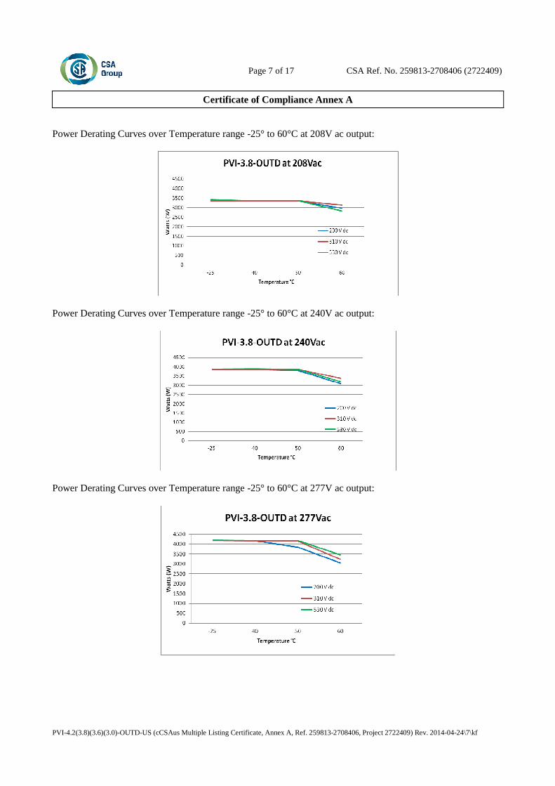
4. Maximum output power can be delivered only with an input voltage range of: 200-530 V dc for 208 V ac configuration 200-530 V dc for 240 V ac configuration 200-530 V dc for 277 V ac configuration
Page 7 of 17 CSA Ref. No. 259813-2708406 (2722409)
Certificate of Compliance Annex A
PVI-4.2(3.8)(3.6)(3.0)-OUTD-US (cCSAus Multiple Listing Certificate, Annex A, Ref. 259813-2708406, Project 2722409) Rev. 2014-04-24\7\kf
Power Derating Curves over Temperature range -25° to 60°C at 208V ac output:
Power Derating Curves over Temperature range -25° to 60°C at 240V ac output:
Power Derating Curves over Temperature range -25° to 60°C at 277V ac output:

Page 8 of 17 CSA Ref. No. 259813-2708406 (2722409)
Certificate of Compliance Annex A
PVI-4.2(3.8)(3.6)(3.0)-OUTD-US (cCSAus Multiple Listing Certificate, Annex A, Ref. 259813-2708406, Project 2722409) Rev. 2014-04-24\8\kf
5. Inverter Models PVI-3.8-OUTD-US, PVI-3.8-OUTD-S-US, PVI-3.8-OUTD-S-US-A, and
PVI-3,8-OUTD-US-W are intended to be used in an ungrounded power system in conjunction with the requirements specified in the National Electrical Code, ANSI/NFPA 70, 2005 Ed, section 690.35.
6. Maximum Output Fault Current and Duration: Models Output
Voltage Fault Current RMS (A)
Duration (mSec) 3 cycles
Fault Current PK (A)
Total Duration (mSec)
PVI-3.8-OUTD Series 208 11.6 50.0 224.0 89.0 PVI-3.8-OUTD Series 240 12.8 50.0 336.0 100.8 PVI-3.8-OUTD Series 277 13.0 50.0 276.0 96.4 7. Utility Interconnection and Voltage and Frequency Trip Limits and Trip Times:
Voltage and frequency limits for utility Interaction Condition Simulated utility source Maximum time (sec) at
60 Hza before cessation of current to the simulated
utility
Voltage (V) Frequency (Hz)
A < 0.50 Vnorb Rated (60 Hz) 0.16 (Fixed)
B 0.50 Vnorb ≤ V < 0.88 Vnor
(Adjustable) Rated (60 Hz) 2 (Fixed)
C 1.10 Vnorb < V < 1.20Vnor (*)
(Adjustable) Rated (60 Hz) 1 (Fixed)
D 1.20Vnor ≤ V (*) Rated (60 Hz) 0.16 (Default) (Adj. 0.001 to 0.16s)
E Rated f > 60.5 Hz (Default) (Adj. 60.2 to 63.0 Hz)
0.16 (Default) (Adj. 0.16 to 300 sec)
F Rated f < 59.3 Hz (Default)
(Adj. 59.8 to 57.0 Hz) 0.16 (Default)
(Adj. 0.16 to 300 sec) G Rated f < 57.0 Hz 0.16 (Fixed) H Rated f > 63.0 Hz 0.16 (Fixed)
a When a utility frequency other than 60 Hz is used for the test, the maximum number of cycles it takes to cease to export power to the simulated utility shall not exceed the number of cycles a utility frequency of 60 Hz takes regardless of the time the inverter takes to cease to export power to the simulated utility.
b V is the nominal output voltage rating. (*) Note: For model at 277V High Voltage is fixed at 110% Vnor and Very High Voltage is fixed at 111%
Vnor.
8. All models meet the surge requirements of IEEE C62.41.2-2002, Location Category B (6kV). Tests
were performed using ring wave and combination waveforms, both polarities, for common mode and differential mode coupling, 20 pulses each test. After surge testing the units were operational with control functionally verified by frequency and voltage disconnect tests.
9. All above models in this series may include expansion board with wireless antennae option and will be
identified with model designation including “–Z” suffix. 10. Model PVI-3.8-OUTD-S-US-A is provided with PV DC ARC-Fault Circuit Protection for series arcing
faults.
Page 9 of 17 CSA Ref. No. 259813-2708406 (2722409)
Certificate of Compliance Annex A
PVI-4.2(3.8)(3.6)(3.0)-OUTD-US (cCSAus Multiple Listing Certificate, Annex A, Ref. 259813-2708406, Project 2722409) Rev. 2014-04-24\9\kf
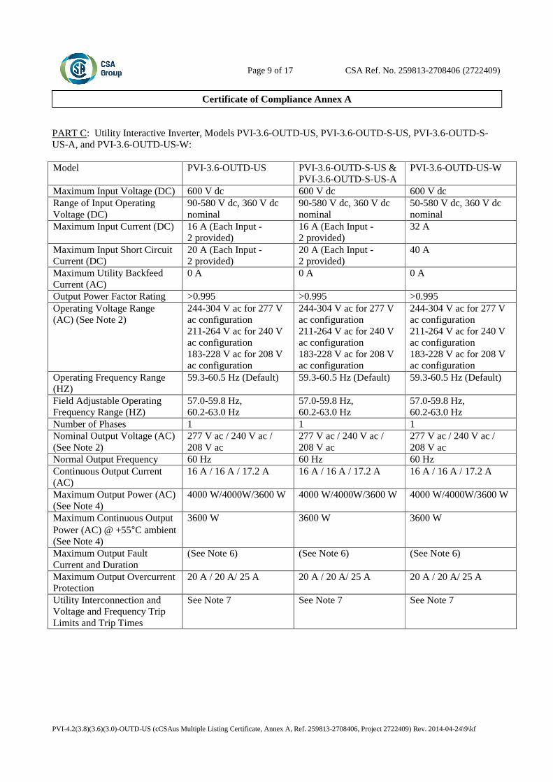
PART C: Utility Interactive Inverter, Models PVI-3.6-OUTD-US, PVI-3.6-OUTD-S-US, PVI-3.6-OUTD-S-US-A, and PVI-3.6-OUTD-US-W: Model PVI-3.6-OUTD-US PVI-3.6-OUTD-S-US &
PVI-3.6-OUTD-S-US-A PVI-3.6-OUTD-US-W
Maximum Input Voltage (DC) 600 V dc 600 V dc 600 V dc Range of Input Operating Voltage (DC)
90-580 V dc, 360 V dc nominal
90-580 V dc, 360 V dc nominal
50-580 V dc, 360 V dc nominal
Maximum Input Current (DC) 16 A (Each Input - 2 provided)
16 A (Each Input - 2 provided)
32 A
Maximum Input Short Circuit Current (DC)
20 A (Each Input - 2 provided)
20 A (Each Input - 2 provided)
40 A
Maximum Utility Backfeed Current (AC)
0 A 0 A 0 A
Output Power Factor Rating >0.995 >0.995 >0.995 Operating Voltage Range (AC) (See Note 2)
244-304 V ac for 277 V ac configuration 211-264 V ac for 240 V ac configuration 183-228 V ac for 208 V ac configuration
244-304 V ac for 277 V ac configuration 211-264 V ac for 240 V ac configuration 183-228 V ac for 208 V ac configuration
244-304 V ac for 277 V ac configuration 211-264 V ac for 240 V ac configuration 183-228 V ac for 208 V ac configuration
Operating Frequency Range (HZ)
59.3-60.5 Hz (Default) 59.3-60.5 Hz (Default) 59.3-60.5 Hz (Default)
Field Adjustable Operating Frequency Range (HZ)
57.0-59.8 Hz, 60.2-63.0 Hz
57.0-59.8 Hz, 60.2-63.0 Hz
57.0-59.8 Hz, 60.2-63.0 Hz
Number of Phases 1 1 1 Nominal Output Voltage (AC) (See Note 2)
277 V ac / 240 V ac / 208 V ac
277 V ac / 240 V ac / 208 V ac
277 V ac / 240 V ac / 208 V ac
Normal Output Frequency 60 Hz 60 Hz 60 Hz Continuous Output Current (AC)
16 A / 16 A / 17.2 A 16 A / 16 A / 17.2 A 16 A / 16 A / 17.2 A
Maximum Output Power (AC) (See Note 4)
4000 W/4000W/3600 W 4000 W/4000W/3600 W 4000 W/4000W/3600 W
Maximum Continuous Output Power (AC) @ +55°C ambient (See Note 4)
3600 W 3600 W 3600 W
Maximum Output Fault Current and Duration
(See Note 6) (See Note 6) (See Note 6)
Maximum Output Overcurrent Protection
20 A / 20 A/ 25 A 20 A / 20 A/ 25 A 20 A / 20 A/ 25 A
Utility Interconnection and Voltage and Frequency Trip Limits and Trip Times
See Note 7 See Note 7 See Note 7
Page 10 of 17 CSA Ref. No. 259813-2708406 (2722409)
Certificate of Compliance Annex A
PVI-4.2(3.8)(3.6)(3.0)-OUTD-US (cCSAus Multiple Listing Certificate, Annex A, Ref. 259813-2708406, Project 2722409) Rev. 2014-04-24\10\kf
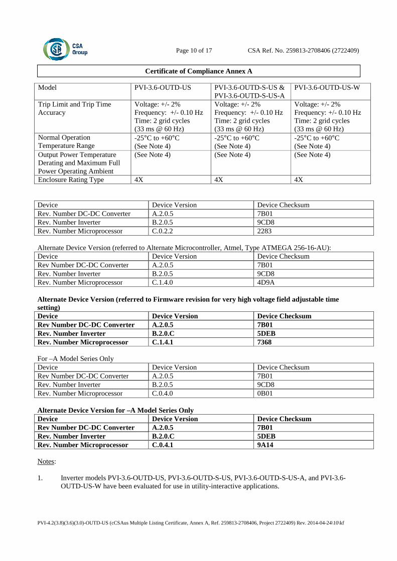
Model PVI-3.6-OUTD-US PVI-3.6-OUTD-S-US & PVI-3.6-OUTD-S-US-A
PVI-3.6-OUTD-US-W
Trip Limit and Trip Time Accuracy
Voltage: +/- 2% Frequency: +/- 0.10 Hz Time: 2 grid cycles (33 ms @ 60 Hz)
Voltage: +/- 2% Frequency: +/- 0.10 Hz Time: 2 grid cycles (33 ms @ 60 Hz)
Voltage: +/- 2% Frequency: +/- 0.10 Hz Time: 2 grid cycles (33 ms @ 60 Hz)
Normal Operation Temperature Range
-25°C to +60°C (See Note 4)
-25°C to +60°C (See Note 4)
-25°C to +60°C (See Note 4)
Output Power Temperature Derating and Maximum Full Power Operating Ambient
(See Note 4) (See Note 4) (See Note 4)
Enclosure Rating Type 4X 4X 4X Device Device Version Device Checksum Rev. Number DC-DC Converter A.2.0.5 7B01 Rev. Number Inverter B.2.0.5 9CD8 Rev. Number Microprocessor C.0.2.2 2283 Alternate Device Version (referred to Alternate Microcontroller, Atmel, Type ATMEGA 256-16-AU): Device Device Version Device Checksum Rev Number DC-DC Converter A.2.0.5 7B01 Rev. Number Inverter B.2.0.5 9CD8 Rev. Number Microprocessor C.1.4.0 4D9A Alternate Device Version (referred to Firmware revision for very high voltage field adjustable time setting) Device Device Version Device Checksum Rev Number DC-DC Converter A.2.0.5 7B01 Rev. Number Inverter B.2.0.C 5DEB Rev. Number Microprocessor C.1.4.1 7368 For –A Model Series Only Device Device Version Device Checksum Rev Number DC-DC Converter A.2.0.5 7B01 Rev. Number Inverter B.2.0.5 9CD8 Rev. Number Microprocessor C.0.4.0 0B01 Alternate Device Version for –A Model Series Only Device Device Version Device Checksum Rev Number DC-DC Converter A.2.0.5 7B01 Rev. Number Inverter B.2.0.C 5DEB Rev. Number Microprocessor C.0.4.1 9A14 Notes: 1. Inverter models PVI-3.6-OUTD-US, PVI-3.6-OUTD-S-US, PVI-3.6-OUTD-S-US-A, and PVI-3.6-
OUTD-US-W have been evaluated for use in utility-interactive applications.

Page 11 of 17 CSA Ref. No. 259813-2708406 (2722409)
Certificate of Compliance Annex A
PVI-4.2(3.8)(3.6)(3.0)-OUTD-US (cCSAus Multiple Listing Certificate, Annex A, Ref. 259813-2708406, Project 2722409) Rev. 2014-04-24\11\kf
2. The output of Inverter, models PVI-3.6-OUTD-US, PVI-3.6-OUTD-S-US, PVI-3.6-OUTD-S-US-A,
and PVI-3.6-OUTD-US-W may be 277 V ac, 240 V ac or 208 V ac which is user settable based on the utility system.
3. Inverter Model PVI-3.6-OUTD-US-W is intended for operation with an AC Generated supply (i.e. wind
or hydro); this inverter is intended to receive an input supply from a certified interface module (rectifier-controller which converts AC voltage from an AC generator into a regulated DC voltage).
4. Maximum output power can be delivered only with an input voltage range of: 220-530 V dc for 208 V ac configuration 200-530 V dc for 240 V ac configuration 200-530 V dc for 277 V ac configuration Power Derating Curves over Temperature range -25° to 60°C at 208V ac output:
PVI-3.6-OUTD
2600
2800
3000
3200
3400
3600
3800
-25º C 40º C 50º C 60º C
Temp.
Wa
tts
200V dc
310V dc
530V dc
Power Derating Curves over Temperature range -25° to 60°C at 240V ac output:
PVI-3.6-OUTD
0500
10001500200025003000350040004500
-25º C 40º C 50º C 60º C
Temp.
Wa
tts
200V dc
310V dc
530V dc

Page 12 of 17 CSA Ref. No. 259813-2708406 (2722409)
Certificate of Compliance Annex A
PVI-4.2(3.8)(3.6)(3.0)-OUTD-US (cCSAus Multiple Listing Certificate, Annex A, Ref. 259813-2708406, Project 2722409) Rev. 2014-04-24\12\kf
Power Derating Curves over Temperature range -25° to 60°C at 277V ac output:
PVI-3.6-OUTD
0500
10001500200025003000350040004500
-25º C 40º C 50º C 60º C
Temp.
Wa
tts
200V dc
310V dc
530V dc
5. Inverter Models PVI-3.6-OUTD-US, PVI-3.6-OUTD-S-US, PVI-3.6-OUTD-S-US-A, and PVI-3.6-
OUTD-US-W are intended to be used in an ungrounded power system in conjunction with the requirements specified in the National Electrical Code, ANSI/NFPA 70, 2005 Ed, section 690.35.
6. Maximum Output Fault Current and Duration:
Models Output Voltage
Fault Current RMS (A)
Duration (mSec) 3 cycles
Fault Current PK (A)
Total Duration (mSec)
PVI-3.6-OUTD Series 208 12.2 49.92 93.9 124.4 PVI-3.6-OUTD Series 240 12.5 49.92 136.5 120.2 PVI-3.6-OUTD Series 277 11.3 49.92 164.6 116.3
7. Utility Interconnection and Voltage and Frequency Trip Limits and Trip Times:
Table 68.1 Voltage and frequency limits for utility Interaction
Condition Simulated utility source Maximum time (sec) at 60 Hza before cessation of current to the simulated
utility
Voltage (V) Frequency (Hz)
A < 0.50 Vnorb Rated (60 Hz) 0.16 (Fixed)
B 0.50 Vnorb ≤ V < 0.88 Vnor
(Adjustable) Rated (60 Hz) 2 (Fixed)
C 1.10 Vnorb < V < 1.20Vnor (*)
(Adjustable) Rated (60 Hz) 1 (Fixed)
D 1.20Vnor ≤ V (*) Rated (60 Hz) 0.16 (Default) (Adj. 0.001 to 0.16s)
E Rated f > 60.5 Hz (Default) (Adj. 60.2 to 63.0 Hz)
0.16 (Default) (Adj. 0.16 to 300 sec)
F Rated f < 59.3 Hz (Default)
(Adj. 59.8 to 57.0 Hz) 0.16 (Default)
(Adj. 0.16 to 300 sec) G Rated f < 57.0 Hz 0.16 (Fixed) H Rated f > 63.0 Hz 0.16 (Fixed)

Page 13 of 17 CSA Ref. No. 259813-2708406 (2722409)
Certificate of Compliance Annex A
PVI-4.2(3.8)(3.6)(3.0)-OUTD-US (cCSAus Multiple Listing Certificate, Annex A, Ref. 259813-2708406, Project 2722409) Rev. 2014-04-24\13\kf
a When a utility frequency other than 60 Hz is used for the test, the maximum number of cycles it takes to cease to export power to the simulated utility shall not exceed the number of cycles a utility frequency of 60 Hz takes regardless of the time the inverter takes to cease to export power to the simulated utility.
b V is the nominal output voltage rating. (*) Note: For model at 277V High Voltage is fixed at 110% Vnor and Very High Voltage is fixed at 111%
Vnor.
8. All models meet the surge requirements of IEEE C62.41.2-2002, Location Category B (6kV). Tests
were performed using ring wave and combination waveforms, both polarities, for common mode and differential mode coupling, 20 pulses each test. After surge testing the units were operational with control functionally verified by frequency and voltage disconnect tests.
9. All above models in this series may include expansion board with wireless antennae option and will be
identified with model designation including “–Z” suffix. 10. Model PVI-3.6-OUTD-S-US-A is provided with PV DC ARC-Fault Circuit Protection for series arcing
faults. PART D Utility Interactive Inverter, Models PVI-3.0-OUTD-US, PVI-3.0-OUTD-S-US, PVI-3.0-OUTD-S-US-A, and PVI-3.0-OUTD-US-W: Model PVI-3.0-OUTD-US PVI-3.0-OUTD-S-US &
PVI-3.0-OUTD-S-US-A PVI-3.0-OUTD-US-W
Maximum Input Voltage (DC)
600 V dc 600 V dc 600 V dc
Range of Input Operating Voltage (DC)
90-580 V dc, 360 V dc nominal
90-580 V dc, 360 V dc nominal
50-580 V dc, 360 V dc nominal
Maximum Input Current (DC)
10 A (Each Input - 2 provided)
10 A (Each Input - 2 provided)
20 A
Maximum Input Short Circuit Current (DC)
12.5 A (Each Input - 2 provided)
12.5 A (Each Input - 2 provided)
25 A
Maximum Utility Backfeed Current (AC)
0 A 0 A 0 A
Output Power Factor Rating >0.995 >0.995 >0.995 Operating Voltage Range (AC) (See Note 2)
244-304 V ac for 277 V ac configuration 211-264 V ac for 240 V ac configuration 183-228 V ac for 208 V ac configuration
244-304 V ac for 277 V ac configuration 211-264 V ac for 240 V ac configuration 183-228 V ac for 208 V ac configuration
244-304 V ac for 277 V ac configuration 211-264 V ac for 240 V ac configuration 183-228 V ac for 208 V ac configuration
Operating Frequency Range (HZ)
59.3-60.5 Hz (Default) 59.3-60.5 Hz (Default) 59.3-60.5 Hz
Field Adjustable Operating Frequency Range (HZ)
57.0-59.8 Hz, 60.2-63.0 Hz
57.0-59.8 Hz, 60.2-63.0 Hz
57.0-59.8 Hz, 60.2-63.0 Hz
Number of Phases 1 1 1 Nominal Output Voltage (AC) (See Note 2)
277 V ac / 240 V ac / 208 V ac
277 V ac / 240 V ac / 208 V ac
277 V ac / 240 V ac / 208 V ac
Normal Output Frequency 60 Hz 60 Hz 60 Hz
Page 14 of 17 CSA Ref. No. 259813-2708406 (2722409)
Certificate of Compliance Annex A
PVI-4.2(3.8)(3.6)(3.0)-OUTD-US (cCSAus Multiple Listing Certificate, Annex A, Ref. 259813-2708406, Project 2722409) Rev. 2014-04-24\14\kf
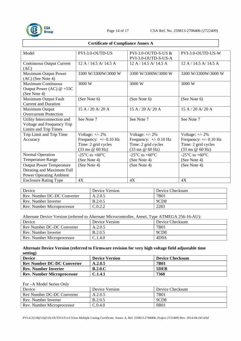
Model PVI-3.0-OUTD-US PVI-3.0-OUTD-S-US & PVI-3.0-OUTD-S-US-A
PVI-3.0-OUTD-US-W
Continuous Output Current (AC)
12 A / 14.5 A/ 14.5 A 12 A / 14.5 A/ 14.5 A 12 A / 14.5 A/ 14.5 A
Maximum Output Power (AC) (See Note 4)
3300 W/3300W/3000 W 3300 W/3300W/3000 W 3300 W/3300W/3000 W
Maximum Continuous Output Power (AC) @ +55C (See Note 4)
3000 W 3000 W 3000 W
Maximum Output Fault Current and Duration
(See Note 6) (See Note 6) (See Note 6)
Maximum Output Overcurrent Protection
15 A / 20 A/ 20 A 15 A / 20 A/ 20 A 15 A / 20 A/ 20 A
Utility Interconnection and Voltage and Frequency Trip Limits and Trip Times
See Note 7 See Note 7 See Note 7
Trip Limit and Trip Time Accuracy
Voltage: +/- 2% Frequency: +/- 0.10 Hz Time: 2 grid cycles (33 ms @ 60 Hz)
Voltage: +/- 2% Frequency: +/- 0.10 Hz Time: 2 grid cycles (33 ms @ 60 Hz)
Voltage: +/- 2% Frequency: +/- 0.10 Hz Time: 2 grid cycles (33 ms @ 60 Hz)
Normal Operation Temperature Range
-25°C to +60°C (See Note 4)
-25°C to +60°C (See Note 4)
-25°C to +60°C (See Note 4)
Output Power Temperature Derating and Maximum Full Power Operating Ambient
(See Note 4) (See Note 4) (See Note 4)
Enclosure Rating Type 4X 4X 4X Device Device Version Device Checksum Rev. Number DC-DC Converter A.2.0.5 7B01 Rev. Number Inverter B.2.0.5 9CD8 Rev. Number Microprocessor C.0.2.2 2283 Alternate Device Version (referred to Alternate Microcontroller, Atmel, Type ATMEGA 256-16-AU): Device Device Version Device Checksum Rev Number DC-DC Converter A.2.0.5 7B01 Rev. Number Inverter B.2.0.5 9CD8 Rev. Number Microprocessor C.1.4.0 4D9A Alternate Device Version (referred to Firmware revision for very high voltage field adjustable time setting) Device Device Version Device Checksum Rev Number DC-DC Converter A.2.0.5 7B01 Rev. Number Inverter B.2.0.C 5DEB Rev. Number Microprocessor C.1.4.1 7368 For –A Model Series Only Device Device Version Device Checksum Rev Number DC-DC Converter A.2.0.5 7B01 Rev. Number Inverter B.2.0.5 9CD8 Rev. Number Microprocessor C.0.4.0 0B01
Page 15 of 17 CSA Ref. No. 259813-2708406 (2722409)
Certificate of Compliance Annex A
PVI-4.2(3.8)(3.6)(3.0)-OUTD-US (cCSAus Multiple Listing Certificate, Annex A, Ref. 259813-2708406, Project 2722409) Rev. 2014-04-24\15\kf
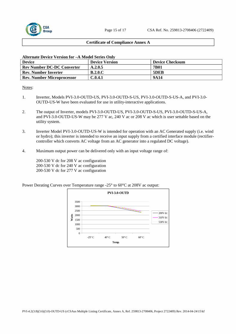
Alternate Device Version for –A Model Series Only Device Device Version Device Checksum Rev Number DC-DC Converter A.2.0.5 7B01 Rev. Number Inverter B.2.0.C 5DEB Rev. Number Microprocessor C.0.4.1 9A14 Notes: 1. Inverter, Models PVI-3.0-OUTD-US, PVI-3.0-OUTD-S-US, PVI-3.0-OUTD-S-US-A, and PVI-3.0-
OUTD-US-W have been evaluated for use in utility-interactive applications. 2. The output of Inverter, models PVI-3.0-OUTD-US, PVI-3.0-OUTD-S-US, PVI-3.0-OUTD-S-US-A,
and PVI-3.0-OUTD-US-W may be 277 V ac, 240 V ac or 208 V ac which is user settable based on the utility system.
3. Inverter Model PVI-3.0-OUTD-US-W is intended for operation with an AC Generated supply (i.e. wind
or hydro); this inverter is intended to receive an input supply from a certified interface module (rectifier-controller which converts AC voltage from an AC generator into a regulated DC voltage).
4. Maximum output power can be delivered only with an input voltage range of: 200-530 V dc for 208 V ac configuration 200-530 V dc for 240 V ac configuration 200-530 V dc for 277 V ac configuration Power Derating Curves over Temperature range -25° to 60°C at 208V ac output:
PVI-3.0-OUTD
0
500
1000
1500
2000
2500
3000
3500
-25º C 40º C 50º C 60º C
Temp.
Wa
tts
200V dc
310V dc
530V dc
Page 16 of 17 CSA Ref. No. 259813-2708406 (2722409)
Certificate of Compliance Annex A
PVI-4.2(3.8)(3.6)(3.0)-OUTD-US (cCSAus Multiple Listing Certificate, Annex A, Ref. 259813-2708406, Project 2722409) Rev. 2014-04-24\16\kf
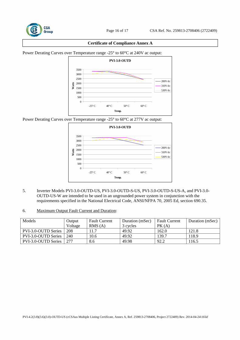
Power Derating Curves over Temperature range -25° to 60°C at 240V ac output:
PVI-3.0-OUTD
0
500
1000
1500
2000
2500
3000
3500
-25º C 40º C 50º C 60º C
Temp.
Wa
tts
200V dc
310V dc
530V dc
Power Derating Curves over Temperature range -25° to 60°C at 277V ac output:
PVI-3.0-OUTD
0
500
1000
1500
2000
2500
3000
3500
-25º C 40º C 50º C 60º C
Temp.
Wa
tts
200V dc
310V dc
530V dc
5. Inverter Models PVI-3.0-OUTD-US, PVI-3.0-OUTD-S-US, PVI-3.0-OUTD-S-US-A, and PVI-3.0-
OUTD-US-W are intended to be used in an ungrounded power system in conjunction with the requirements specified in the National Electrical Code, ANSI/NFPA 70, 2005 Ed, section 690.35.
6. Maximum Output Fault Current and Duration: Models Output
Voltage Fault Current RMS (A)
Duration (mSec) 3 cycles
Fault Current PK (A)
Duration (mSec)
PVI-3.0-OUTD Series 208 11.7 49.92 162.0 121.8 PVI-3.0-OUTD Series 240 10.6 49.92 139.7 118.9 PVI-3.0-OUTD Series 277 8.6 49.98 92.2 116.5

Page 17 of 17 CSA Ref. No. 259813-2708406 (2722409)
Certificate of Compliance Annex A
PVI-4.2(3.8)(3.6)(3.0)-OUTD-US (cCSAus Multiple Listing Certificate, Annex A, Ref. 259813-2708406, Project 2722409) Rev. 2014-04-24\17\kf
7. Utility Interconnection and Voltage and Frequency Trip Limits and Trip Times:
Table 68.1 Voltage and frequency limits for utility Interaction
Condition Simulated utility source Maximum time (sec) at 60 Hza before cessation of current to the simulated
utility
Voltage (V) Frequency (Hz)
A < 0.50 Vnorb Rated (60 Hz) 0.16 (Fixed)
B 0.50 Vnorb ≤ V < 0.88 Vnor
(Adjustable) Rated (60 Hz) 2 (Fixed)
C 1.10 Vnorb < V < 1.20Vnor (*)
(Adjustable) Rated (60 Hz) 1 (Fixed)
D 1.20Vnor ≤ V (*) Rated (60 Hz) 0.16 (Default) (Adj. 0.001 to 0.16s)
E Rated f > 60.5 Hz (Default) (Adj. 60.2 to 63.0 Hz)
0.16 (Default) (Adj. 0.16 to 300 sec)
F Rated f < 59.3 Hz (Default)
(Adj. 59.8 to 57.0 Hz) 0.16 (Default)
(Adj. 0.16 to 300 sec) G Rated f < 57.0 Hz 0.16 (Fixed) H Rated f > 63.0 Hz 0.16 (Fixed)
a When a utility frequency other than 60 Hz is used for the test, the maximum number of cycles it takes to cease to export power to the simulated utility shall not exceed the number of cycles a utility frequency of 60 Hz takes regardless of the time the inverter takes to cease to export power to the simulated utility.
b V is the nominal output voltage rating. (*) Note: For model at 277V High Voltage is fixed at 110% Vnor and Very High Voltage is fixed at 111%
Vnor.
8. All models meet the surge requirements of IEEE C62.41.2-2002, Location Category B (6kV). Tests
were performed using ring wave and combination waveforms, both polarities, for common mode and differential mode coupling, 20 pulses each test. After surge testing the units were operational with control functionally verified by frequency and voltage disconnect tests.
9. All above models in this series may include expansion board with wireless antennae option and will be
identified with model designation including “–Z” suffix. 10. Model PVI-3.0-OUTD-S-US-A is provided with PV DC ARC-Fault Circuit Protection for series arcing
faults.