Embed Size (px)
Citation preview
ibm.com/redbooks
IBM Eserver pSeries HACMP V5.x Certification StudyGuide Update
Dino QuinteroAndrei Socoliuc
Tony SteelOctavian Lascu
The latest HACMP features are explained
Sample exercise questions are included
Use as a deskside reference guide
Front cover


IBM Eserver pSeries HACMP V5.x Certification Study Guide Update
February 2006
International Technical Support Organization
SG24-6375-01

© Copyright International Business Machines Corporation 2004, 2006. All rights reserved.Note to U.S. Government Users Restricted Rights -- Use, duplication or disclosure restricted by GSA ADPSchedule Contract with IBM Corp.
Second Edition (February 2006)
This edition applies to Version 5 of HACMP for AIX (product number 5765-F62).
Note: Before using this information and the product it supports, read the information in “Notices” on page xi.
Contents
Notices . . . . . . . . . . . . . . . . . . . . . . . . . . . . . . . . . . . . . . . . . . . . . . . . . . . . . . . ixTrademarks . . . . . . . . . . . . . . . . . . . . . . . . . . . . . . . . . . . . . . . . . . . . . . . . . . . . x
Preface . . . . . . . . . . . . . . . . . . . . . . . . . . . . . . . . . . . . . . . . . . . . . . . . . . . . . . . xiThe team that wrote this redbook. . . . . . . . . . . . . . . . . . . . . . . . . . . . . . . . . . . xiiBecome a published author . . . . . . . . . . . . . . . . . . . . . . . . . . . . . . . . . . . . . . . xiiiComments welcome. . . . . . . . . . . . . . . . . . . . . . . . . . . . . . . . . . . . . . . . . . . . . xiii
Chapter 1. Introduction . . . . . . . . . . . . . . . . . . . . . . . . . . . . . . . . . . . . . . . . . . 11.1 What is HACMP? . . . . . . . . . . . . . . . . . . . . . . . . . . . . . . . . . . . . . . . . . . . . 2
1.1.1 History and evolution. . . . . . . . . . . . . . . . . . . . . . . . . . . . . . . . . . . . . . 41.1.2 High availability concepts . . . . . . . . . . . . . . . . . . . . . . . . . . . . . . . . . . 61.1.3 High availability versus fault tolerance . . . . . . . . . . . . . . . . . . . . . . . . 71.1.4 High availability solutions . . . . . . . . . . . . . . . . . . . . . . . . . . . . . . . . . . 8
1.2 HACMP concepts . . . . . . . . . . . . . . . . . . . . . . . . . . . . . . . . . . . . . . . . . . . . 91.2.1 HACMP terminology . . . . . . . . . . . . . . . . . . . . . . . . . . . . . . . . . . . . . 10
1.3 HACMP/XD (extended distance). . . . . . . . . . . . . . . . . . . . . . . . . . . . . . . . 111.3.1 HACMP/XD: HAGEO components . . . . . . . . . . . . . . . . . . . . . . . . . . 131.3.2 HACMP/XD: HAGEO basic configurations . . . . . . . . . . . . . . . . . . . . 141.3.3 HACMP/XD PPRC integration feature . . . . . . . . . . . . . . . . . . . . . . . 14
Chapter 2. Planning and design. . . . . . . . . . . . . . . . . . . . . . . . . . . . . . . . . . 172.1 Planning considerations . . . . . . . . . . . . . . . . . . . . . . . . . . . . . . . . . . . . . . 18
2.1.1 Sizing: Choosing the nodes in the cluster . . . . . . . . . . . . . . . . . . . . . 182.1.2 Sizing: Storage considerations . . . . . . . . . . . . . . . . . . . . . . . . . . . . . 192.1.3 Network considerations. . . . . . . . . . . . . . . . . . . . . . . . . . . . . . . . . . . 19
2.2 HACMP cluster planning . . . . . . . . . . . . . . . . . . . . . . . . . . . . . . . . . . . . . . 202.2.1 Node configurations . . . . . . . . . . . . . . . . . . . . . . . . . . . . . . . . . . . . . 212.2.2 Network configuration . . . . . . . . . . . . . . . . . . . . . . . . . . . . . . . . . . . . 212.2.3 HACMP networking terminology . . . . . . . . . . . . . . . . . . . . . . . . . . . . 222.2.4 Network types . . . . . . . . . . . . . . . . . . . . . . . . . . . . . . . . . . . . . . . . . . 272.2.5 Choosing the IP address takeover (IPAT) method . . . . . . . . . . . . . . 282.2.6 Planning for network security . . . . . . . . . . . . . . . . . . . . . . . . . . . . . . 31
2.3 HACMP heartbeat . . . . . . . . . . . . . . . . . . . . . . . . . . . . . . . . . . . . . . . . . . . 332.3.1 Heartbeat via disk . . . . . . . . . . . . . . . . . . . . . . . . . . . . . . . . . . . . . . . 352.3.2 Heartbeat over IP aliases . . . . . . . . . . . . . . . . . . . . . . . . . . . . . . . . . 36
2.4 Shared storage configuration . . . . . . . . . . . . . . . . . . . . . . . . . . . . . . . . . . 392.4.1 Shared LVM requirements . . . . . . . . . . . . . . . . . . . . . . . . . . . . . . . . 402.4.2 Non-Concurrent, Enhanced Concurrent, and Concurrent . . . . . . . . . 41
© Copyright IBM Corp. 2004, 2006. All rights reserved. iii

2.4.3 Choosing a disk technology . . . . . . . . . . . . . . . . . . . . . . . . . . . . . . . 452.5 Software planning . . . . . . . . . . . . . . . . . . . . . . . . . . . . . . . . . . . . . . . . . . . 48
2.5.1 AIX level and related requirements . . . . . . . . . . . . . . . . . . . . . . . . . . 492.5.2 Application compatibility . . . . . . . . . . . . . . . . . . . . . . . . . . . . . . . . . . 502.5.3 Planning NFS configurations. . . . . . . . . . . . . . . . . . . . . . . . . . . . . . . 512.5.4 Licensing . . . . . . . . . . . . . . . . . . . . . . . . . . . . . . . . . . . . . . . . . . . . . . 522.5.5 Client connections. . . . . . . . . . . . . . . . . . . . . . . . . . . . . . . . . . . . . . . 53
2.6 Operating system space requirements . . . . . . . . . . . . . . . . . . . . . . . . . . . 532.7 Resource group planning . . . . . . . . . . . . . . . . . . . . . . . . . . . . . . . . . . . . . 54
2.7.1 Cascading resource groups . . . . . . . . . . . . . . . . . . . . . . . . . . . . . . . 562.7.2 Rotating resource groups . . . . . . . . . . . . . . . . . . . . . . . . . . . . . . . . . 572.7.3 Concurrent resource groups . . . . . . . . . . . . . . . . . . . . . . . . . . . . . . . 582.7.4 Custom resource groups. . . . . . . . . . . . . . . . . . . . . . . . . . . . . . . . . . 582.7.5 Application monitoring. . . . . . . . . . . . . . . . . . . . . . . . . . . . . . . . . . . . 59
2.8 Disaster recovery planning . . . . . . . . . . . . . . . . . . . . . . . . . . . . . . . . . . . . 612.9 Review. . . . . . . . . . . . . . . . . . . . . . . . . . . . . . . . . . . . . . . . . . . . . . . . . . . . 64
2.9.1 Sample questions . . . . . . . . . . . . . . . . . . . . . . . . . . . . . . . . . . . . . . . 64
Chapter 3. Installation and configuration . . . . . . . . . . . . . . . . . . . . . . . . . . 693.1 HACMP software installation. . . . . . . . . . . . . . . . . . . . . . . . . . . . . . . . . . . 70
3.1.1 Checking for prerequisites . . . . . . . . . . . . . . . . . . . . . . . . . . . . . . . . 703.1.2 New installation . . . . . . . . . . . . . . . . . . . . . . . . . . . . . . . . . . . . . . . . . 713.1.3 Installing HACMP . . . . . . . . . . . . . . . . . . . . . . . . . . . . . . . . . . . . . . . 713.1.4 Migration paths and options . . . . . . . . . . . . . . . . . . . . . . . . . . . . . . . 723.1.5 Converting a cluster snapshot. . . . . . . . . . . . . . . . . . . . . . . . . . . . . . 733.1.6 Node-by-node migration . . . . . . . . . . . . . . . . . . . . . . . . . . . . . . . . . . 773.1.7 Upgrade options . . . . . . . . . . . . . . . . . . . . . . . . . . . . . . . . . . . . . . . . 84
3.2 Network configuration . . . . . . . . . . . . . . . . . . . . . . . . . . . . . . . . . . . . . . . . 863.2.1 Types of networks . . . . . . . . . . . . . . . . . . . . . . . . . . . . . . . . . . . . . . . 873.2.2 TCP/IP networks . . . . . . . . . . . . . . . . . . . . . . . . . . . . . . . . . . . . . . . . 87
3.3 Storage configuration . . . . . . . . . . . . . . . . . . . . . . . . . . . . . . . . . . . . . . . . 913.3.1 Shared LVM . . . . . . . . . . . . . . . . . . . . . . . . . . . . . . . . . . . . . . . . . . . 973.3.2 Non-concurrrent access mode . . . . . . . . . . . . . . . . . . . . . . . . . . . . . 983.3.3 Concurrent access mode . . . . . . . . . . . . . . . . . . . . . . . . . . . . . . . . 1003.3.4 Enhanced concurrent mode (ECM) VGs. . . . . . . . . . . . . . . . . . . . . 1013.3.5 Fast disk takeover . . . . . . . . . . . . . . . . . . . . . . . . . . . . . . . . . . . . . . 103
3.4 Configuring cluster topology . . . . . . . . . . . . . . . . . . . . . . . . . . . . . . . . . . 1043.4.1 HACMP V5.x Standard and Extended configurations. . . . . . . . . . . 1043.4.2 Define cluster topology . . . . . . . . . . . . . . . . . . . . . . . . . . . . . . . . . . 1153.4.3 Defining a node . . . . . . . . . . . . . . . . . . . . . . . . . . . . . . . . . . . . . . . . 1183.4.4 Defining sites. . . . . . . . . . . . . . . . . . . . . . . . . . . . . . . . . . . . . . . . . . 1183.4.5 Defining network(s) . . . . . . . . . . . . . . . . . . . . . . . . . . . . . . . . . . . . . 1193.4.6 Defining communication interfaces . . . . . . . . . . . . . . . . . . . . . . . . . 121
iv IBM Eserver pSeries HACMP V5.x Certification Study Guide Update

3.4.7 Defining communication devices. . . . . . . . . . . . . . . . . . . . . . . . . . . 1233.4.8 Boot IP labels . . . . . . . . . . . . . . . . . . . . . . . . . . . . . . . . . . . . . . . . . 1253.4.9 Defining persistent IP labels . . . . . . . . . . . . . . . . . . . . . . . . . . . . . . 1263.4.10 Define HACMP network modules . . . . . . . . . . . . . . . . . . . . . . . . . 1273.4.11 Synchronize topology . . . . . . . . . . . . . . . . . . . . . . . . . . . . . . . . . . 128
3.5 Resource group configuration . . . . . . . . . . . . . . . . . . . . . . . . . . . . . . . . . 1283.5.1 Cascading resource groups . . . . . . . . . . . . . . . . . . . . . . . . . . . . . . 1283.5.2 Rotating resource groups . . . . . . . . . . . . . . . . . . . . . . . . . . . . . . . . 1313.5.3 Concurrent access resource groups . . . . . . . . . . . . . . . . . . . . . . . . 1333.5.4 Custom resource groups. . . . . . . . . . . . . . . . . . . . . . . . . . . . . . . . . 1333.5.5 Configuring HACMP resource groups using the standard path . . . 1353.5.6 Configure HACMP resource group with extended path . . . . . . . . . 1393.5.7 Configuring custom resource groups . . . . . . . . . . . . . . . . . . . . . . . 1453.5.8 Verify and synchronize HACMP . . . . . . . . . . . . . . . . . . . . . . . . . . . 151
3.6 Review. . . . . . . . . . . . . . . . . . . . . . . . . . . . . . . . . . . . . . . . . . . . . . . . . . . 1543.6.1 Sample questions . . . . . . . . . . . . . . . . . . . . . . . . . . . . . . . . . . . . . . 154
Chapter 4. Cluster verification and testing . . . . . . . . . . . . . . . . . . . . . . . . 1594.1 Will it all work?. . . . . . . . . . . . . . . . . . . . . . . . . . . . . . . . . . . . . . . . . . . . . 160
4.1.1 Hardware and license prerequisites . . . . . . . . . . . . . . . . . . . . . . . . 1604.1.2 Operating system settings. . . . . . . . . . . . . . . . . . . . . . . . . . . . . . . . 1604.1.3 Cluster environment . . . . . . . . . . . . . . . . . . . . . . . . . . . . . . . . . . . . 161
4.2 Cluster start . . . . . . . . . . . . . . . . . . . . . . . . . . . . . . . . . . . . . . . . . . . . . . . 1624.2.1 Verifying the cluster services . . . . . . . . . . . . . . . . . . . . . . . . . . . . . 1624.2.2 IP verification. . . . . . . . . . . . . . . . . . . . . . . . . . . . . . . . . . . . . . . . . . 1644.2.3 Resource verification. . . . . . . . . . . . . . . . . . . . . . . . . . . . . . . . . . . . 1644.2.4 Application verification . . . . . . . . . . . . . . . . . . . . . . . . . . . . . . . . . . 164
4.3 Monitoring cluster status . . . . . . . . . . . . . . . . . . . . . . . . . . . . . . . . . . . . . 1664.3.1 Using clstat . . . . . . . . . . . . . . . . . . . . . . . . . . . . . . . . . . . . . . . . . . . 1664.3.2 Using snmpinfo . . . . . . . . . . . . . . . . . . . . . . . . . . . . . . . . . . . . . . . . 1674.3.3 Using Tivoli . . . . . . . . . . . . . . . . . . . . . . . . . . . . . . . . . . . . . . . . . . . 167
4.4 Cluster stop . . . . . . . . . . . . . . . . . . . . . . . . . . . . . . . . . . . . . . . . . . . . . . . 1684.5 Application monitoring . . . . . . . . . . . . . . . . . . . . . . . . . . . . . . . . . . . . . . . 171
4.5.1 Verifying application status . . . . . . . . . . . . . . . . . . . . . . . . . . . . . . . 1724.5.2 Verifying resource group status . . . . . . . . . . . . . . . . . . . . . . . . . . . 1734.5.3 Verifying NFS functionality . . . . . . . . . . . . . . . . . . . . . . . . . . . . . . . 175
4.6 Cluster behavior on node failover . . . . . . . . . . . . . . . . . . . . . . . . . . . . . . 1774.7 Testing IP networks. . . . . . . . . . . . . . . . . . . . . . . . . . . . . . . . . . . . . . . . . 177
4.7.1 Communication adapter failure . . . . . . . . . . . . . . . . . . . . . . . . . . . . 1784.7.2 Network failure . . . . . . . . . . . . . . . . . . . . . . . . . . . . . . . . . . . . . . . . 1784.7.3 Verifying persistent IP labels. . . . . . . . . . . . . . . . . . . . . . . . . . . . . . 179
4.8 Testing non-IP networks . . . . . . . . . . . . . . . . . . . . . . . . . . . . . . . . . . . . . 1794.8.1 Serial networks . . . . . . . . . . . . . . . . . . . . . . . . . . . . . . . . . . . . . . . . 179
Contents v
4.8.2 SCSI networks . . . . . . . . . . . . . . . . . . . . . . . . . . . . . . . . . . . . . . . . 1804.8.3 SSA networks . . . . . . . . . . . . . . . . . . . . . . . . . . . . . . . . . . . . . . . . . 1804.8.4 Heartbeat over disk networks . . . . . . . . . . . . . . . . . . . . . . . . . . . . . 181
4.9 Cluster behavior on other failures . . . . . . . . . . . . . . . . . . . . . . . . . . . . . . 1824.9.1 Hardware components failures . . . . . . . . . . . . . . . . . . . . . . . . . . . . 1824.9.2 Rootvg mirror and internal disk failure . . . . . . . . . . . . . . . . . . . . . . 1834.9.3 AIX and LVM level errors . . . . . . . . . . . . . . . . . . . . . . . . . . . . . . . . 1834.9.4 Forced varyon of VGs . . . . . . . . . . . . . . . . . . . . . . . . . . . . . . . . . . . 183
4.10 RSCT verification . . . . . . . . . . . . . . . . . . . . . . . . . . . . . . . . . . . . . . . . . 1854.11 Review. . . . . . . . . . . . . . . . . . . . . . . . . . . . . . . . . . . . . . . . . . . . . . . . . . 189
4.11.1 Sample questions . . . . . . . . . . . . . . . . . . . . . . . . . . . . . . . . . . . . . 189
Chapter 5. Post implementation and administration . . . . . . . . . . . . . . . . 1935.1 Using C-SPOC . . . . . . . . . . . . . . . . . . . . . . . . . . . . . . . . . . . . . . . . . . . . 194
5.1.1 C-SPOC overview . . . . . . . . . . . . . . . . . . . . . . . . . . . . . . . . . . . . . . 1965.1.2 C-SPOC enhancements in HACMP V5.1 . . . . . . . . . . . . . . . . . . . . 1995.1.3 Configuration changes: DARE . . . . . . . . . . . . . . . . . . . . . . . . . . . . 2005.1.4 Managing users and groups . . . . . . . . . . . . . . . . . . . . . . . . . . . . . . 2055.1.5 Managing cluster storage using C-SPOC LVM. . . . . . . . . . . . . . . . 208
5.2 Managing resource groups . . . . . . . . . . . . . . . . . . . . . . . . . . . . . . . . . . . 2145.2.1 Resource group movement. . . . . . . . . . . . . . . . . . . . . . . . . . . . . . . 2155.2.2 Priority Override Location (POL) . . . . . . . . . . . . . . . . . . . . . . . . . . . 2155.2.3 Changing resource groups . . . . . . . . . . . . . . . . . . . . . . . . . . . . . . . 2195.2.4 Creating a new resource group. . . . . . . . . . . . . . . . . . . . . . . . . . . . 2255.2.5 Bringing a resource group online . . . . . . . . . . . . . . . . . . . . . . . . . . 2275.2.6 Bringing a resource group offline . . . . . . . . . . . . . . . . . . . . . . . . . . 2315.2.7 Moving a resource group between nodes . . . . . . . . . . . . . . . . . . . . 232
5.3 Problem determination . . . . . . . . . . . . . . . . . . . . . . . . . . . . . . . . . . . . . . 2345.3.1 HACMP logs . . . . . . . . . . . . . . . . . . . . . . . . . . . . . . . . . . . . . . . . . . 2415.3.2 Snapshots . . . . . . . . . . . . . . . . . . . . . . . . . . . . . . . . . . . . . . . . . . . . 243
5.4 Event and error management . . . . . . . . . . . . . . . . . . . . . . . . . . . . . . . . . 2475.4.1 Pre-event and post-event considerations . . . . . . . . . . . . . . . . . . . . 2485.4.2 Custom events . . . . . . . . . . . . . . . . . . . . . . . . . . . . . . . . . . . . . . . . 2495.4.3 Error notification . . . . . . . . . . . . . . . . . . . . . . . . . . . . . . . . . . . . . . . 2505.4.4 Recovery from cluster errors. . . . . . . . . . . . . . . . . . . . . . . . . . . . . . 2515.4.5 Recovery from failed DARE . . . . . . . . . . . . . . . . . . . . . . . . . . . . . . 252
5.5 Review. . . . . . . . . . . . . . . . . . . . . . . . . . . . . . . . . . . . . . . . . . . . . . . . . . . 2525.5.1 Sample questions . . . . . . . . . . . . . . . . . . . . . . . . . . . . . . . . . . . . . . 253
Chapter 6. HACMP V5.2 and V5.3. . . . . . . . . . . . . . . . . . . . . . . . . . . . . . . . 2576.1 Overview . . . . . . . . . . . . . . . . . . . . . . . . . . . . . . . . . . . . . . . . . . . . . . . . . 2586.2 Features and changes in V5.2 . . . . . . . . . . . . . . . . . . . . . . . . . . . . . . . . 2586.3 New features in HACMP 5.3 . . . . . . . . . . . . . . . . . . . . . . . . . . . . . . . . . . 260
vi IBM Eserver pSeries HACMP V5.x Certification Study Guide Update
6.3.1 Migration to HACMP V5.3 issues . . . . . . . . . . . . . . . . . . . . . . . . . . 2616.3.2 Additional improvements. . . . . . . . . . . . . . . . . . . . . . . . . . . . . . . . . 2626.3.3 Two node configuration assistant . . . . . . . . . . . . . . . . . . . . . . . . . . 2626.3.4 Automated test tool . . . . . . . . . . . . . . . . . . . . . . . . . . . . . . . . . . . . . 2636.3.5 Custom (only) resource groups. . . . . . . . . . . . . . . . . . . . . . . . . . . . 2656.3.6 Cluster configuration auto correction . . . . . . . . . . . . . . . . . . . . . . . 2666.3.7 Cluster file collections . . . . . . . . . . . . . . . . . . . . . . . . . . . . . . . . . . . 2686.3.8 Automatic cluster verification . . . . . . . . . . . . . . . . . . . . . . . . . . . . . 2696.3.9 Web-based SMIT management . . . . . . . . . . . . . . . . . . . . . . . . . . . 2706.3.10 Resource group dependencies . . . . . . . . . . . . . . . . . . . . . . . . . . . 2706.3.11 Application monitoring changes . . . . . . . . . . . . . . . . . . . . . . . . . . 2726.3.12 Enhanced online planning worksheets . . . . . . . . . . . . . . . . . . . . . 2736.3.13 User password management . . . . . . . . . . . . . . . . . . . . . . . . . . . . 2776.3.14 HACMP Smart Assist for WebSphere Application Server (SAW) . 2786.3.15 New security features . . . . . . . . . . . . . . . . . . . . . . . . . . . . . . . . . . 2786.3.16 Dynamic LPARs support and CUoD support . . . . . . . . . . . . . . . . 2796.3.17 Cluster lock manager not available anymore . . . . . . . . . . . . . . . . 2806.3.18 Cross-site LVM mirroring . . . . . . . . . . . . . . . . . . . . . . . . . . . . . . . 2816.3.19 RMC replaces Event Management (EM) . . . . . . . . . . . . . . . . . . . 282
Appendix A. ITSO sample cluster . . . . . . . . . . . . . . . . . . . . . . . . . . . . . . . 285Cluster hardware . . . . . . . . . . . . . . . . . . . . . . . . . . . . . . . . . . . . . . . . . . . . . . 286Cluster installed software . . . . . . . . . . . . . . . . . . . . . . . . . . . . . . . . . . . . . . . . 286Cluster storage . . . . . . . . . . . . . . . . . . . . . . . . . . . . . . . . . . . . . . . . . . . . . . . . 290Cluster networking environment. . . . . . . . . . . . . . . . . . . . . . . . . . . . . . . . . . . 291Application scripts . . . . . . . . . . . . . . . . . . . . . . . . . . . . . . . . . . . . . . . . . . . . . 292Answers to the quizzes . . . . . . . . . . . . . . . . . . . . . . . . . . . . . . . . . . . . . . . . . 294
Chapter 2 quiz. . . . . . . . . . . . . . . . . . . . . . . . . . . . . . . . . . . . . . . . . . . . . . 294Chapter 3 quiz. . . . . . . . . . . . . . . . . . . . . . . . . . . . . . . . . . . . . . . . . . . . . . 294Chapter 4 quiz. . . . . . . . . . . . . . . . . . . . . . . . . . . . . . . . . . . . . . . . . . . . . . 295Chapter 5 quiz. . . . . . . . . . . . . . . . . . . . . . . . . . . . . . . . . . . . . . . . . . . . . . 295
Abbreviations and acronyms . . . . . . . . . . . . . . . . . . . . . . . . . . . . . . . . . . . 297
Related publications . . . . . . . . . . . . . . . . . . . . . . . . . . . . . . . . . . . . . . . . . . 299IBM Redbooks . . . . . . . . . . . . . . . . . . . . . . . . . . . . . . . . . . . . . . . . . . . . . . . . 299Other publications . . . . . . . . . . . . . . . . . . . . . . . . . . . . . . . . . . . . . . . . . . . . . 299Online resources . . . . . . . . . . . . . . . . . . . . . . . . . . . . . . . . . . . . . . . . . . . . . . 300How to get IBM Redbooks . . . . . . . . . . . . . . . . . . . . . . . . . . . . . . . . . . . . . . . 300Help from IBM . . . . . . . . . . . . . . . . . . . . . . . . . . . . . . . . . . . . . . . . . . . . . . . . 300
Index . . . . . . . . . . . . . . . . . . . . . . . . . . . . . . . . . . . . . . . . . . . . . . . . . . . . . . . 301
Contents vii

viii IBM Eserver pSeries HACMP V5.x Certification Study Guide Update

Notices
This information was developed for products and services offered in the U.S.A.
IBM may not offer the products, services, or features discussed in this document in other countries. Consult your local IBM representative for information on the products and services currently available in your area. Any reference to an IBM product, program, or service is not intended to state or imply that only that IBM product, program, or service may be used. Any functionally equivalent product, program, or service that does not infringe any IBM intellectual property right may be used instead. However, it is the user's responsibility to evaluate and verify the operation of any non-IBM product, program, or service.
IBM may have patents or pending patent applications covering subject matter described in this document. The furnishing of this document does not give you any license to these patents. You can send license inquiries, in writing, to: IBM Director of Licensing, IBM Corporation, North Castle Drive Armonk, NY 10504-1785 U.S.A.
The following paragraph does not apply to the United Kingdom or any other country where such provisions are inconsistent with local law: INTERNATIONAL BUSINESS MACHINES CORPORATION PROVIDES THIS PUBLICATION "AS IS" WITHOUT WARRANTY OF ANY KIND, EITHER EXPRESS OR IMPLIED, INCLUDING, BUT NOT LIMITED TO, THE IMPLIED WARRANTIES OF NON-INFRINGEMENT, MERCHANTABILITY OR FITNESS FOR A PARTICULAR PURPOSE. Some states do not allow disclaimer of express or implied warranties in certain transactions, therefore, this statement may not apply to you.
This information could include technical inaccuracies or typographical errors. Changes are periodically made to the information herein; these changes will be incorporated in new editions of the publication. IBM may make improvements and/or changes in the product(s) and/or the program(s) described in this publication at any time without notice.
Any references in this information to non-IBM Web sites are provided for convenience only and do not in any manner serve as an endorsement of those Web sites. The materials at those Web sites are not part of the materials for this IBM product and use of those Web sites is at your own risk.
IBM may use or distribute any of the information you supply in any way it believes appropriate without incurring any obligation to you.
Information concerning non-IBM products was obtained from the suppliers of those products, their published announcements or other publicly available sources. IBM has not tested those products and cannot confirm the accuracy of performance, compatibility or any other claims related to non-IBM products. Questions on the capabilities of non-IBM products should be addressed to the suppliers of those products.
This information contains examples of data and reports used in daily business operations. To illustrate them as completely as possible, the examples include the names of individuals, companies, brands, and products. All of these names are fictitious and any similarity to the names and addresses used by an actual business enterprise is entirely coincidental.
COPYRIGHT LICENSE: This information contains sample application programs in source language, which illustrates programming techniques on various operating platforms. You may copy, modify, and distribute these sample programs in any form without payment to IBM, for the purposes of developing, using, marketing or distributing application programs conforming to the application programming interface for the operating platform for which the sample programs are written. These examples have not been thoroughly tested under all conditions. IBM, therefore, cannot guarantee or imply reliability, serviceability, or function of these programs. You may copy, modify, and distribute these sample programs in any form without payment to IBM for the purposes of developing, using, marketing, or distributing application programs conforming to IBM's application programming interfaces.
© Copyright IBM Corp. 2004, 2006. All rights reserved. ix

TrademarksThe following terms are trademarks of the International Business Machines Corporation in the United States, other countries, or both:
Eserver®Eserver®Redbooks (logo) ™pSeries®AIX 5L™AIX®
DB2®Enterprise Storage Server®FlashCopy®HACMP™IBM®Magstar®
Redbooks™RS/6000®Seascape®Tivoli®TotalStorage®WebSphere®
The following terms are trademarks of other companies:
Java, JavaScript, Ultra, and all Java-based trademarks are trademarks of Sun Microsystems, Inc. in the United States, other countries, or both.
bookshelf, Windows, and the Windows logo are trademarks of Microsoft Corporation in the United States, other countries, or both.
UNIX is a registered trademark of The Open Group in the United States and other countries.
Linux is a trademark of Linus Torvalds in the United States, other countries, or both.
Other company, product, or service names may be trademarks or service marks of others.
x IBM Eserver pSeries HACMP V5.x Certification Study Guide Update
Preface
This IBM® Redbook update is designed as a study guide for professionals wanting to prepare for the certification exam to achieve IBM Eserver® Certified Systems Expert - pSeries® HACMP™ 5.x for AIX® 5L™.
The pSeries HACMP 5.x for AIX 5L certification validates the skills required to successfully plan, install, configure, and support an HACMP 5.x for AIX 5L cluster installation. The requirements for this include a working knowledge of the following:
� Hardware options supported for use in a cluster, along with the considerations that affect the choices made.
� AIX 5L parameters that are affected by an HACMP 5.x installation, and their correct settings.
� The cluster and resource configuration process, including how to choose the best resource configuration for a customer requirement.
� Customization of the standard HACMP 5.x facilities to satisfy special customer requirements.
� Diagnosis and troubleshooting knowledge and skills.
This redbook helps AIX 5L professionals seeking a comprehensive and task-oriented guide for developing the knowledge and skills required for the certification. It is designed to provide a combination of theory and practical experience.
This redbook does not replace the practical experience you should have, but, when combined with educational activities and experience, should prove to be a very useful preparation guide for the exam. Due to the practical nature of the certification content, this publication can also be used as a deskside reference.
So, whether you are planning to take the pSeries HACMP 5.x for AIX 5L certification exam, or just want to validate your HACMP skills, this redbook is for you. For additional information about certification and instructions about how to register for an exam, contact IBM Learning Services or visit our Web site at:
http://www.ibm.com/certify
© Copyright IBM Corp. 2004, 2006. All rights reserved. xi

The team that wrote this redbookThis redbook was produced by a team of specialists from around the world working at the International Technical Support Organization, Poughkeepsie Center.
Dino Quintero is a Senior Certified Consulting IT Specialist at the ITSO in Poughkeepsie, New York. Before joining the ITSO, he worked as a Performance Analyst for the Enterprise Systems Group and as a Disaster Recovery Architect for IBM Global Services. His areas of expertise include disaster recovery and pSeries clustering solutions. He is certified on pSeries system administration and pSeries clustering technologies. He is also an IBM Senior Certified Professional on pSeries technologies. Currently, he leads teams delivering redbook solutions on pSeries clustering technologies and delivering technical workshops worldwide.
Andrei Socoliuc is an IT specialist at IBM Global Services in Romania. He provides technical support for the RS/6000® and IBM Eserver pSeries. He is an IBM Certified Specialist in AIX and HACMP. His areas of expertise include AIX, HACMP, PSSP, and TSM. He holds a master’s degree in Computer Science from the Polytechnical University in Bucharest.
Tony Steel is a Senior IT Specialist in ITS Australia. He has 12 years experience in the UNIX® field, predominately AIX and Linux®. He holds an honors degree in Theoretical Chemistry from the University of Sydney. His areas of expertise include scripting, system customization, performance, networking, high availability and problem solving. He has written and presented on LVM, TCP/IP, and high availability both in Australia and throughout Asia Pacific. This is the fourth redbook he has co-authored.
Octavian Lascu is a Project Leader at the International Technical Support Organization, Poughkeepsie Center. He writes extensively and teaches IBM classes worldwide in all areas of pSeries clusters and Linux. Before joining the ITSO, Octavian worked in IBM Global Services Romania as a software and hardware Services Manager. He holds a master's degree in Electronic Engineering from the Polytechnical Institute in Bucharest and is also an IBM Certified Advanced Technical Expert in AIX/PSSP/HACMP. He has worked with IBM since 1992.
Thanks to the following people for their contributions to this project:
Paul Moyer, Elaine KrakowerIBM Poughkeepsie
Gabrielle VelezInternational Technical Support Organization
xii IBM Eserver pSeries HACMP V5.x Certification Study Guide Update

Become a published authorJoin us for a two- to six-week residency program! Help write an IBM Redbook dealing with specific products or solutions, while getting hands-on experience with leading-edge technologies. You'll team with IBM technical professionals, Business Partners and/or customers.
Your efforts will help increase product acceptance and customer satisfaction. As a bonus, you'll develop a network of contacts in IBM development labs, and increase your productivity and marketability.
Find out more about the residency program, browse the residency index, and apply online at:
ibm.com/redbooks/residencies.html
Comments welcomeYour comments are important to us!
We want our Redbooks™ to be as helpful as possible. Send us your comments about this or other Redbooks in one of the following ways:
� Use the online Contact us review redbook form found at:
ibm.com/redbooks
� Send your comments in an Internet note to:
� Mail your comments to:
IBM Corporation, International Technical Support OrganizationDept. JN9B Mail Station P0992455 South RoadPoughkeepsie, NY 12601-5400
Preface xiii

xiv IBM Eserver pSeries HACMP V5.x Certification Study Guide Update
Chapter 1. Introduction
This chapter contains an introduction to IBM High Availability Cluster Multi-Processing (HACMP) for AIX product line, and the concepts on which IBM high availability products are based.
The following topics are discussed:
� What is HACMP?
� History and evolution
� High availability concepts
� High availability versus fault tolerance
1
© Copyright IBM Corp. 2004, 2006. All rights reserved. 1
1.1 What is HACMP?Before we explain what is HACMP, we have to define the concept of high availability.
High availabilityIn today’s complex environments, providing continuous service for applications is a key component of a successful IT implementation. High availability is one of the components that contributes to providing continuous service for the application clients, by masking or eliminating both planned and unplanned systems and application downtime. This is achieved through the elimination of hardware and software single points of failure (SPOFs).
A high availability solution will ensure that the failure of any component of the solution, either hardware, software, or system management, will not cause the application and its data to be unavailable to the user.
High Availability Solutions should eliminate single points of failure (SPOF) through appropriate design, planning, selection of hardware, configuration of software, and carefully controlled change management discipline.
DowntimeThe downtime is the time frame when an application is not available to serve its clients. We can classify the downtime as:
� Planned:
– Hardware upgrades
– Repairs
– Software updates/upgrades
– Backups (offline backups)
– Testing (periodic testing is required for cluster validation.)
– Development
� Unplanned:
– Administrator errors
– Application failures
– Hardware failures
– Environmental disasters
2 IBM Eserver pSeries HACMP V5.x Certification Study Guide Update
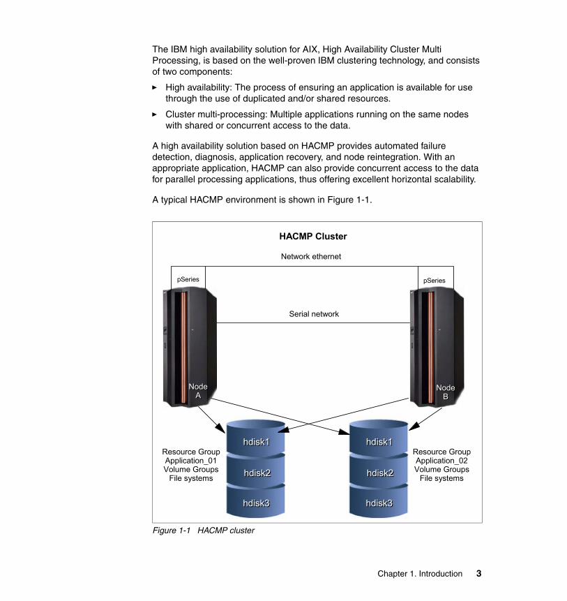
The IBM high availability solution for AIX, High Availability Cluster Multi Processing, is based on the well-proven IBM clustering technology, and consists of two components:
� High availability: The process of ensuring an application is available for use through the use of duplicated and/or shared resources.
� Cluster multi-processing: Multiple applications running on the same nodes with shared or concurrent access to the data.
A high availability solution based on HACMP provides automated failure detection, diagnosis, application recovery, and node reintegration. With an appropriate application, HACMP can also provide concurrent access to the data for parallel processing applications, thus offering excellent horizontal scalability.
A typical HACMP environment is shown in Figure 1-1.
Figure 1-1 HACMP cluster
HACMP Cluster
pSeries
Node Node AA
pSeries
Network ethernet
Serial network
Node Node BB
Resource GroupApplication_01Volume Groups
File systems
hdisk1hdisk1
hdisk2hdisk2
hdisk3hdisk3
hdisk1hdisk1
hdisk2hdisk2
hdisk3hdisk3
Resource GroupApplication_02Volume Groups
File systems
Chapter 1. Introduction 3

1.1.1 History and evolutionIBM High Availability Cluster Multi-Processing goes back to the early 1990s. HACMP development started in 1990 to provide high availability solution for applications running on RS/6000 servers.
We do not provide information about the very early releases, since those releases are nor supported or in use at the time this book was developed, instead, we provide highlights about the most recent versions.
HACMP V4.2.2Along with HACMP Classic (HAS), this version introduced the enhanced scalability version (ES) based on RSCT (Reliable Scalable Clustering Technology) topology, group, and event management services, derived from PSSP (Parallel Systems Support Program).
HACMP V4.3.XThis version introduced, among other aspects, 32 node support for HACMP/ES, C-SPOC enhancements, ATM network support, HACMP Task guides (GUI for simplifying cluster configuration), multiple pre- and post- event scripts, FDDI MAC address takeover, monitoring and administration support enhancements, node by node migration, and AIX fast connect support.
HACMP V4.4.XNew items in this version are integration with Tivoli®, application monitoring, cascading with out fallback, C-SPOC enhancements, improved migration support, integration of HA-NFS functionality, and soft copy documentation (HTML and PDF).
HACMP V4.5In this version, AIX 5L is required, and there is an automated configuration discovery feature, multiple service labels on each network adapter (through the use of IP aliasing), persistent IP address support, 64-bit-capable APIs, and monitoring and recovery from loss of volume group quorum.
HACMP V5.1This is the version that introduced major changes, from configuration simplification and performance enhancements to changing HACMP terminology. Some of the important new features in HACMP V5.1 were:
� SMIT “Standard” and “Extended” configuration paths (procedures)
� Automated configuration discovery
� Custom resource groups
� Non IP networks based on heartbeating over disks
4 IBM Eserver pSeries HACMP V5.x Certification Study Guide Update

� Fast disk takeover
� Forced varyon of volume groups
� Heartbeating over IP aliases
� HACMP “classic” (HAS) has been dropped; now there is only HACMP/ES, based on IBM Reliable Scalable Cluster Technology
� Improved security, by using cluster communication daemon (eliminates the need of using standard AIX “r” commands, thus eliminating the need for the /.rhosts file)
� Improved performance for cluster customization and synchronization
� Normalization of HACMP terminology
� Simplification of configuration and maintenance
� Online Planning Worksheets enhancements
� Forced varyon of volume groups
� Custom resource groups
� Heartbeat monitoring of service IP addresses/labels on takeover node(s)
� Heartbeating over IP aliases
� Heartbeating over disks
� Various C-SPOC enhancements
� GPFS integration
� Fast disk takeover
� Cluster verification enhancements
� Improved resource group management
HACMP V5.2Starting July 2004, the new HACMP V5.2 added more improvements in management, configuration simplification, automation, and performance areas. Here is a summary of the improvements in HACMP V5.2:
� Two-Node Configuration Assistant, with both SMIT menus and a Java™ interface (in addition to the SMIT “Standard” and “Extended” configuration paths).
� File collections.
� User password management.
� Classic resource groups are not used anymore, having been replaced by custom resource groups.
� Automated test procedures.
Chapter 1. Introduction 5

� Automatic cluster verification.
� Improved Online Planning Worksheets (OLPW) can now import a configuration from an existing HACMP cluster.
� Event management (EM) has been replaced by resource monitoring and a control (RMC) subsystem (standard in AIX).
� Enhanced security.
� Resource group dependencies.
� Self-healing clusters.
1.1.2 High availability conceptsWhat needs to be protected? Ultimately, the goal of any IT solution in a critical environment is to provide continuous service and data protection.
The high availability is just one building block in achieving the continuous operation goal. The high availability is based on the availability of the hardware, software (operating system and its components), application, and network components.
For a high availability solution you need:
� Redundant servers
� Redundant networks
� Redundant network adapters
� Monitoring
� Failure detection
� Failure diagnosis
� Automated fallover
� Automated reintegration
The main objective of the HACMP is eliminate Single Points of Failure (SPOFs) (see Table 1-1 on page 7).
Note: At the time this redbook was developed, both HACMP V5.1 and V5.2 were available. The certification exam only contains HACMP V5.1 topics.
6 IBM Eserver pSeries HACMP V5.x Certification Study Guide Update

Table 1-1 Single point of failure
Each of the items listed in Table 1-1 in the Cluster Object column is a physical or logical component that, if it fails, will result in the application being unavailable for serving clients.
1.1.3 High availability versus fault toleranceThe systems for the detection and handling of the hardware and software failures can be defined in two groups:
� Fault-tolerant systems� High availability systems
Fault-tolerant systemsThe systems provided with fault tolerance are designed to operate virtually without interruption, regardless of the failure that may occur (except perhaps for a complete site down due to a natural disaster). In such systems, ALL components are at least duplicated for either software or hardware.
Thus, CPUs, memory, and disks have a special design and provide continuous service, even if one sub-component fails.
Such systems are very expensive and extremely specialized. Implementing a fault tolerant solution requires a lot of effort and a high degree of customization for all system components.
Cluster object Eliminated as a single point of failure by:
Node (servers) Multiple nodes
Power supply Multiple circuits and/or power supplies
Network adapter Redundant network adapters
Network Multiple networks to connect nodes
TCP/IP subsystem A non- IP networks to back up TCP/IP
Disk adapter Redundant disk adapters
Disk Redundant hardware and disk mirroring or RAID technology
Application Configuring application monitoring and backup node(s) to acquire the application engine and data
Chapter 1. Introduction 7
In places where no downtime is acceptable (life support and so on), fault-tolerant equipment and solutions are required.
High availability systemsThe systems configured for high availability are a combination of hardware and software components configured in such a way to ensure automated recovery in case of failure with a minimal acceptable downtime.
In such systems, the software involved detects problems in the environment, and then provides the transfer of the application on another machine, taking over the identity of the original machine (node).
Thus, it is very important to eliminate all single points of failure (SPOF) in the environment. For example, if the machine has only one network connection, a second network interface should be provided in the same node to take over in case the primary adapter providing the service fails.
Another important issue is to protect the data by mirroring and placing it on shared disk areas accessible from any machine in the cluster.
The HACMP (High Availability Cluster Multi-Processing) software provides the framework and a set of tools for integrating applications in a highly available system.
Applications to be integrated in a HACMP cluster require a fair amount of customization, not at the application level, but rather at the HACMP and AIX platform level.
HACMP is a flexible platform that allows integration of generic applications running on AIX platform, providing for high available systems at a reasonable cost.
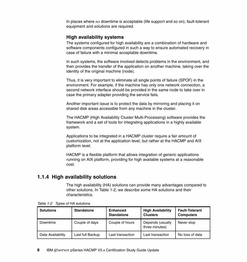
1.1.4 High availability solutionsThe high availability (HA) solutions can provide many advantages compared to other solutions. In Table 1-2, we describe some HA solutions and their characteristics.
Table 1-2 Types of HA solutions
Solutions Standalone Enhanced Standalone
High Availability Clusters
Fault-Tolerant Computers
Downtime Couple of days Couple of hours Depends (usually three minutes)
Never stop
Data Availability Last full Backup Last transaction Last transaction No loss of data
8 IBM Eserver pSeries HACMP V5.x Certification Study Guide Update
High availability solutions offer the following benefits:
� Standard components
� Can be used with the existing hardware
� Works with just about any application
� Works with a wide range of disk and network types
� Excellent availability at reasonable cost
The IBM high available solution for the IBM Eserver pSeries offers some distinct benefits. Such benefits include:
� Proven solution (more than 14 years of product development)
� Flexibility (virtually any application running on a standalone AIX system can be protected with HACMP)
� Using “of the shelf” hardware components
� Proven commitment for supporting our customers
Considerations for providing high availability solutions include:
� Thorough design and detailed planning
� Elimination of single points of failure
� Selection of appropriate hardware
� Correct implementation (no “shortcuts”)
� Disciplined system administration practices
� Documented operational procedures
� Comprehensive testing
1.2 HACMP conceptsThe basic concepts of HACMP can be classified as follows:
� Cluster topology
Contains basic cluster components nodes, networks, communication interfaces, communication devices, and communication adapters.
� Cluster resources
Entities that are being made highly available (for example, file systems, raw devices, service IP labels, and applications). Resources are grouped together in resource groups (RGs), which HACMP keeps highly available as a single entity.
Chapter 1. Introduction 9
Resource groups can be available from a single node or, in the case of concurrent applications, available simultaneously from multiple nodes.
� Fallover
Represents the movement of a resource group from one active node to another node (backup node) in response to a failure on that active node.
� Fallback
Represents the movement of a resource group back from the backup node to the previous node, when it becomes available. This movement is typically in response to the reintegration of the previously failed node.
1.2.1 HACMP terminologyTo understand the correct functionality and utilization of HACMP, it is necessary to know some important terms:
� Cluster
Loosely-coupled collection of independent systems (nodes) or LPARs organized into a network for the purpose of sharing resources and communicating with each other.
HACMP defines relationships among cooperating systems where peer cluster nodes provide the services offered by a cluster node should that node be unable to do so.
These individual nodes are together responsible for maintaining the functionality of one or more applications in case of a failure of any cluster component.
� Node
An IBM Eserver pSeries machine (or LPAR) running AIX and HACMP that is defined as part of a cluster. Each node has a collection of resources (disks, file systems, IP address(es), and applications) that can be transferred to another node in the cluster in case the node fails.
� Resource
Resources are logical components of the cluster configuration that can be moved from one node to another. All the logical resources necessary to provide a Highly Available application or service are grouped together in a resource group (RG).
The components in a resource group move together from one node to another in the event of a node failure. A cluster may have more than one resource group, thus allowing for efficient use of the cluster nodes (thus the “Multi-Processing” in HACMP).
10 IBM Eserver pSeries HACMP V5.x Certification Study Guide Update
� Takeover
It is the operation of transferring resources between nodes inside the cluster. If one node fails due to a hardware problem or crash of AIX, its resources application will be moved to the another node.
� Clients
A client is a system that can access the application running on the cluster nodes over a local area network. Clients run a client application that connects to the server (node) where the application runs.
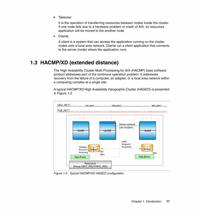
1.3 HACMP/XD (extended distance)The High Availability Cluster Multi-Processing for AIX (HACMP) base software product addresses part of the continuos operation problem. It addresses recovery from the failure of a computer, an adapter, or a local area network within a computing complex at a single site.
A typical HACMP/XD High Availability Geographic Cluster (HAGEO) is presented in Figure 1-2.
Figure 1-2 Typical HACMP/XD HAGEO configuration
GEO_NET1
GMD:fkmgeolv1fkmgeolog
PUB_NET1
icar_geo1 ulise_geo1 ajax_geo1
/fs1/fkm /fkm
StatMap:fkmsmlv1fkmsmlog
fkmvg1
AJAX
fkmvg1
ULISEICAR
Site:ParisSite:Paris Site:Bonn
Resource Group:GEO_RG(YOKO_RG)
Serial network(via modem)
Chapter 1. Introduction 11

For protecting an application in case of a major disaster (site failure), additional software is needed. HAGEO provides:
� Ability to configure a cluster with geographically separate sites.
HAGEO extends HACMP to encompass two geographically distant data centers or sites. This extension prevents an individual site from being a single point of failure within the cluster.
The geo-mirroring process supplies each site with an updated copy of essential data.
Either site can run key applications, ensuring that mission-critical computing resources remain continuously available at a geographically separate site if a failure or disaster disables one site.
� Automatic failure detection and notification.
HAGEO works with HACMP to provide automatic detection of a site or geographic network failure. It initiates the recovery process and notifies the system administrator about all failures it detects and actions it takes in response.
� Automatic fallover
HAGEO includes event scripts to handle recovery from a site or geographic network failure. These scripts are integrated with the standard HACMP event scripts.
You can customize the behavior for your configuration by adding pre- or post- event scripts, just as you can for HACMP.
� Fast recovery from a disaster.
HAGEO also provides fast recovery of data and applications at the operable site. The geo-mirroring process ensures that the data is already available at the second site when a disaster strikes.
Recovery time typically takes minutes, not including the application recovery time.
� Automatic resynchronization of data during site recovery.
HAGEO handles the resynchronization of the mirrors on each site as an integral part of the site recovery process. The nodes at the rejoining site are automatically updated with the data received while the site was in failure.
� Reliable data integrity and consistency.
HAGEO’s geographic mirroring and geographic messaging components ensure that if a site fails, the surviving site’s data is consistent with the failed site’s data.
12 IBM Eserver pSeries HACMP V5.x Certification Study Guide Update
When the failed site reintegrates into the cluster, HAGEO updates that site with the current data from the operable site, once again ensuring data consistency.
� Flexible, scalable configurations.
HAGEO software supports a wide range of configurations, allowing you to configure the disaster recovery solution unique to your needs.
You can have up to eight nodes in an HAGEO cluster, with varying numbers of nodes at each site.
HAGEO is file system and database independent, since the geo-mirroring device behaves the same as the disk devices it supports. Because the mirroring is transparent, applications configured to use geo-mirroring do not have to be modified in any way.
1.3.1 HACMP/XD: HAGEO componentsThe software has three significant functions:
� GeoMirror:
Consists of a logical device and a pseudo device driver that mirrors at a second site; the data is entered at one site. TCP/IP is used as a transport for mirrored data.
GeoMirror can be used in synchronous and asynchronous mode, depending on the communication bandwidth between sites, and the application transaction volume (which determines the amount of changed data).
� GeoMessage:
Provides reliable delivery of data and messages between GeoMirror devices at the two sites.
� Geographic topology:
Provides the logic for integrating the geo-mirroring facilities with HACMP facilities to provide automatic failure detection and recovery from events that affect entire sites.
� Recovering from disaster
When a disaster causes a site failure, the Cluster Manager on nodes at the surviving site detects the situation quickly and takes action to keep geo-mirrored applications available.
Likewise, if the cluster is partitioned due to global geographic network failure, then the Cluster Manager on the site configured as non-dominant will bring itself down in order to avoid data divergence.
Chapter 1. Introduction 13
1.3.2 HACMP/XD: HAGEO basic configurationsYou can configure an HAGEO cluster in any of the configurations supported by the HACMP base software. These include standby, one-sided takeover, mutual takeover, and concurrent access configurations.
� Standby configurations
The standby configuration is a traditional redundant hardware configuration where one or more nodes in the cluster stand idle until a server node fails.
In HAGEO, this translates to having an idle site. A site is not completely idle since it may also be involved in the geo-mirroring process. But nodes at this site do not perform application work.
� Takeover configurations
In a takeover configuration, all nodes are processing; no idle nodes exist. Configurations include:
– Intrasite (local) takeover
– Remote one-sided takeover
– Remote mutual takeover
� Concurrent configurations
In a concurrent access configuration, all nodes at one site have simultaneous access to the concurrent volume group and own the same disk resources. The other site is set up the same way.
If a node leaves the site, availability of the resources is not affected, since other nodes have the concurrent volume group varied on.
If a site fails, the other site offers concurrent access on nodes at that site. A concurrent application can be accessed by all nodes in the cluster.
The HACMP Cluster Lock Manager must be running on all nodes in the cluster. Not all databases can be used for concurrent access that involves nodes across the geography.
1.3.3 HACMP/XD PPRC integration featureThis feature, introduced in simultaneously in HACMP V4.5 PTF5 and HACMP V5.1, provides automated site fallover and activation of remote copies of application data in an environment where the IBM Enterprise Storage Server® (ESS) is used in both sites and the Peer to Peer Remote Copy (PPRC) facility provides storage volumes mirroring.
14 IBM Eserver pSeries HACMP V5.x Certification Study Guide Update

In case of primary site failure, data should be available for use at the secondary site (replicated via PPRC). The data copy in the secondary site must be activated in order to be used for processing.
The HACMP/XD PPRC integration feature provides automated copy split in case of primary site failure and automated reintegration when the primary site becomes available.
For detailed information, see High Availability Cluster Multi-Processing XD (Extended Distance) V5.1: Concepts and Facilities for HAGEO Technology, SA22-7955.
Chapter 1. Introduction 15

16 IBM Eserver pSeries HACMP V5.x Certification Study Guide Update

Chapter 2. Planning and design
When planning and desiging a high availability cluster, you must follow all customer requirements. You should have a good understanding of the hardware and networking configuration and of the applications that are to be made highly available. You should also be able to control the behavior of the applications in a failure situation.
Knowing the behavior of the application in a failure situation is important to controlling how the cluster will react in such a situation.
The information necessary for planning and implementing a cluster should cover applications, environment, hardware, networks, storage, and also support and change procedures.
This chapter describes the following HACMP cluster topics:
� Node sizing considerations� Cluster hardware planning� Software planning� Storage planning� Disaster recovery planning
Note: Planning is one half of a successful implementation, but when it comes to HACMP, we cannot emphasize enough that proper planning is needed. If planning is not done properly, you may find yourself entangled in restrictions at a later point, and recovering from these restrictions can be a painful experience. So
2
© Copyright IBM Corp. 2004, 2006. All rights reserved. 17

take your time and use the planning worksheets that comes with the product; they are invaluable in any migration or problem determination situations or for documenting the plan.
2.1 Planning considerationsWhen planning a high availability cluster, you should consider the sizing of the nodes, storage, network and so on, to provide the necessary resources for the applications to run properly, even in a takeover situation.
2.1.1 Sizing: Choosing the nodes in the clusterBefore you start the implementation of the cluster, you should know how many nodes are required, and the type of the nodes that should be used. The type of nodes to be used is important in terms of the resources required by the applications.
Sizing of the nodes should cover the following aspects:
� CPU (number of CPUs and speed)� Amount of random access memory (RAM) in each node� Disk storage (internal)� Number of communication and disk adapters in each node� Node reliability
The number of nodes in the cluster depends on the number of applications to be made highly available, and also on the degree of availability desired. Having more than one spare node for each application in the cluster increases the overall availability of the applications.
HACMP V5.1 supports a variety of nodes, ranging from desktop systems to high-end servers. SP nodes and Logical Partitions (LPARs) are supported as well. For further information, refer to the HACMP for AIX 5L V5.1 Planning and Installation Guide, SC23-4861-02.
The cluster resource sharing is based on the applications requirements. Nodes that perform tasks that are not directly related to the applications to be made highly available and do not need to share resources with the application nodes should be configured in separate clusters for easier implementation and administration.
Note: The maximum number of nodes in an HACMP V5.1 cluster is 32.
18 IBM Eserver pSeries HACMP V5.x Certification Study Guide Update

All nodes should provide sufficient resources (CPU, memory, and adapters) to sustain execution of all the designated applications in a fail-over situation (to take over the resources from a failing node).
If possible, you should include additional nodes in the cluster, to increase the availability of the cluster; this also provides greater flexibility when performing node failover, reintegration, and maintenance operations.
We recommend using cluster nodes with a similar hardware configuration, especially when implementing clusters with applications in mutual takeover or concurrent configurations. This makes it easier to distribute resources and to perform administrative operations (software maintenance and so on).
2.1.2 Sizing: Storage considerationsIn the most commonly used configurations, applications to be made highly available require a shared storage space for application data. The shared storage space is used either for concurrent access, or for making the data available to the application on the takeover node (in a fail-over situation).
The storage to be used in a cluster should provide shared access from all designated nodes for each application. The technologies currently supported for HACMP shared storage are SCSI, SSA, and Fibre Channel.
The storage configuration should be defined according to application requirements as non-shared (“private”) or shared storage. The private storage may reside on internal disks and is not involved in any takeover activity.
Shared storage should provide mechanisms for controlled access, considering the following reasons:
� Data placed in shared storage must be accessible from whichever node the application may be running at a point in time. In certain cases, the application is running on only one node at a time (non-concurrent), but in some cases, concurrent access to the data must be provided.
� In a non-concurrent environment, if the shared data is updated by the wrong node, this could result in data corruption.
� In a concurrent environment, the application should provide its own data access mechanism, since the storage controlled access mechanisms are by-passed by the platform concurrent software (AIX/HACMP).
2.1.3 Network considerationsWhen you plan the HACMP cluster, the following aspects should be considered:
Chapter 2. Planning and design 19
� IP network topology (routing, switches, and so on)� IP network performance (speed/bandwidth, latency, and redundancy)� ATM and/or X.25 network configuration
The IP networks are used to provide client access to the applications running on the nodes in the cluster, as well as for exchanging heartbeat messages between the cluster nodes. In an HACMP cluster, the heartbeat messages are exchanged via IP networks and point-to-point (non-IP) networks.
HACMP is designed to provide client access through TCP/IP-based networks, X.25, and ATM networks.
2.2 HACMP cluster planningThe cluster planning is perhaps the most important step in implementing a successful configuration. HACMP planning should include the following aspects:
� Hardware planning
– Nodes– Network– Storage
� Software planning
– Operating system version– HACMP version– Application compatibility
� Test and maintenance planning
– The test procedures– Change management– Administrative operations
Hardware planningThe goal in implementing a high availability configuration is to provide highly available service by eliminating single points of failure (hardware, software, and network) and also by masking service interruptions, either planned or unplanned.
The decision factors for node planning are:
� Supported nodes: Machine types, features, supported adapters, power supply (AC, DC, dual power supply versus single power supply, and so on).
� Connectivity and cables: Types of cables, length, connectors, model numbers, conduit routing, cable tray capacity requirements, and availability.
20 IBM Eserver pSeries HACMP V5.x Certification Study Guide Update
2.2.1 Node configurationsHACMP V5.1 supports IBM Eserver pSeries (stand-alone and LPAR mode), IBM SP nodes, as well as existing RS/6000 servers, in any combination of nodes within a cluster. Nodes must meet the minimum requirements for internal memory, internal disk, number of available I/O slots, and operating system compatibility (AIX version).
Items to be considered are:
� Internal disk (number of disks, capacities, and LVM mirroring used?)
� Shared disk capacity and storage data protection method (RAID and LVM mirroring)
� I/O slot limitations and their effect on creating a single point of failure (SPOF)
� Client access to the cluster (network adapters)
� Other LAN devices (switches, routers, and bridges)
� Redundancy of I/O adapters and subsystems
� Redundancy of power supplies
2.2.2 Network configurationThe main objective when planning the cluster networks is to assess the degree of redundancy you need to eliminate network components as potential single points of failure. The following aspects should be considered:
� Network: Nodes connected to multiple physical networks
� For TCP/IP subsystem failure: Non-IP network to help with the decision process
� Network interfaces: Redundant networks adapters on each network (to prevent resource group failover in case a single network interface fails)
When planning the cluster network configuration, you must chose the proper combination for the node connectivity:
� Cluster network topology (switches, routers, and so on).
� The combination of IP and non-IP (point-to-point) networks connect your cluster nodes and the number of connections for each node to all networks.
The method for providing high availability service IP addresses:
� IP address takeover (IPAT) via IP aliases
� IPAT via IP Replacement.
Chapter 2. Planning and design 21

For a complete list of nodes and adapters supported in HACMP configuration, refer to the HACMP for AIX 5L V5.1 Planning and Installation Guide, SC23-4861-02; also, check the IBM support Web site at:
http://www-1.ibm.com/servers/eserver/pseries/ha/
2.2.3 HACMP networking terminologyStarting with HACMP V5.1, the terminology used to describe HACMP configuration and operation has changed dramatically. The reason for this change is to simplify the overall usage and maintenance of HACMP, and also to align the terminology with the IBM product line.
For example, in previous HACMP versions, the term “Adapter”, depending on the context, could have different meanings, which made configuration confusing and difficult.
IP labelThe term IP label represents the name associated with a specific IP address, as defined in the name resolution method used on the cluster nodes (DNS or static - /etc/hosts). This replaces the host name, which may be confused with the output of the hostname command and may not be associated with any IP address.
In HACMP V5.1, the term Adapter has been replaced as follows:
� Service IP Label / Address: An IP label/address over which a service is provided. It may be bound to a single node or shared by multiple nodes, and is kept highly available by HACMP.
� Communication Interface: A physical interface that supports the TCP/IP protocol, represented by its base IP address.
� Communication Device: A physical device representing one end of a point-to-point non-IP network connection, such as /dev/tty1, /dev/tmssa1, /dev/tmscsi1, and /dev/hdisk1.
� Communication Adapter: An X.25 adapter used to provide a highly available communication link.
Service IP address/labelThe service IP address is an IP address used for client access. This service IP address (and its associated label) is monitored by HACMP and is part of a resource group.
22 IBM Eserver pSeries HACMP V5.x Certification Study Guide Update

There are two types of service IP address (label):
� Shared service IP address (label): An IP address that can be configured on multiple nodes and is part of a resource group that can be active only on one node at a time.
� Node-bound service IP address (label): An IP address that can be configured only one node (is not shared by multiple nodes). Typically, this type of service IP address is associated with concurrent resource groups.
The service IP addresses become available when HACMP is started and their associated resource group has an online status.
HACMP communication interfacesThe communication interface definition in HACMP is a logical grouping of the following:
� A logical network interface is the name to which AIX resolves a port (for example, en0) of a physical network adapter.
� A service IP address is an IP address over which services, such as an application, are provided, and over which client nodes communicate.
� A service IP label is a label that maps to the Service IP address.
A communication interface refers to IP-based networks and networks adapters. The networks adapters that are connected to a common physical network are combined into logical networks that are used by HACMP.
Each network adapter is capable of hosting several TCP/IP addresses. When configuring a cluster, you define the IP addresses that HACMP will monitor (base or boot IP addresses) and the IP addresses that HACMP will keep highly available (the service IP addresses) to HACMP.
Heartbeating in HACMP occurs over communication interfaces. HACMP uses the heartbeating facility of the RSCT subsystem (using UDP) to monitor its network interfaces and IP addresses. HACMP passes the network topology defined and stored in the ODM to RSCT, whenever HACMP services are started on that node, and RSCT provides failure notifications to HACMP.
HACMP communication devicesHACMP also provides monitoring of point-to-point non-IP networks. Both ends of a point-to-point network are AIX devices (as defined in /dev directory). These are the communication devices and they include serial RS232 connections, target mode SCSI, target mode SSA, and disk heartbeat connections.
Chapter 2. Planning and design 23
The point-to-point networks are also monitored by RSCT, and their status information is used by HACMP to distinguish between node failure and IP network failure.
For example, a heartbeat over disk uses the disk device name (for example, /dev/hdisk2) as the device configured to HACMP at each end of the connection.
The recommendation for such networks is to have at least one non-IP network defined between any two nodes in the cluster.
In case of disk heartbeat, the recommendation is to have one point-to-point network consisting of one disk per pair of nodes per physical enclosure. One physical disk cannot be used for two point-to-point networks.
Communication adapters and linksYou can define the following communication links as resources in HACMP:
� SNA configured over LAN network adapters (ent*)
� SNA configured over X.25 adapter
� Native X.25 links
HACMP managed these links as part of resource groups, thus ensuring high availability communication links. In the event of a physical network interface failure, an X.25 link failure, or a node failure, the highly available communication link is migrated over to another available adapter on the same node, or on a takeover node (together with all the resources in the same resource group).
IP aliasesAn IP alias is an IP address that is configured on a communication (network) interface in addition to the base IP address. An IP alias is an AIX function that is supported by HACMP. AIX supports multiple IP aliases on each communication interface. Each IP alias on the adapter can be on a separate subnet.
AIX also allows IP aliases with different subnet masks to be configured for an interface; this functionality is not yet supported by HACMP.
IP aliases are used in HACMP both as service and non-service addresses for IP address takeover, as well as for heartbeat configuration.
Network interface functionsFor IP networks, we recommend that you configure more than one communication interface per node per network. The communication interfaces will have specific roles each, depending on the HACMP cluster status.
24 IBM Eserver pSeries HACMP V5.x Certification Study Guide Update

� Service Interface
A service interface is a communications interface configured with one or more service IP addresses (labels). Depending on the IP address takeover (IPAT) method defined for each network, the service IP address will be added on top of the base IP address (IPAT via aliasing), or will replace the base (boot) IP address of the communication interface. This interface is used for providing access to the application(s) running on that node. The service IP address is monitored by HACMP via RSCT heartbeat.
� Boot Interface
This is a communication interface represented by its base (boot) IP address, as defined in an AIX configuration. If heartbeating over IP aliases is used, this IP address will not be monitored by HACMP, but the communication interface will be monitored via the IP alias assigned by HACMP at startup time.
No client traffic is carried over the boot interface; however, if a service interface fails, HACMP will move the service IP address(es) onto a non-service interface. If a node fails, another interface on the takeover node will configure the service IP address when performing a resource group fallover.
� Persistent Node IP Label
A persistent node IP label is an IP alias that can be assigned to a specific node on a cluster network. A persistent node IP label:
– Is node-bound (always stays on the same node).
– Can coexist on a network adapter that already has a service or non-service IP label defined.
– Has the advantage where it does not require installation of an additional physical network adapter on that node.
– Is not part of any resource group.
Assigning a persistent node IP label provides a node-bound IP address, and is useful for administrative purposes, since issuing a connection to a persistent node IP label will always identify that particular cluster node, even if HACMP services are not started on that node.
Note: A node can have from zero to seven non-service interfaces for each network. Using multiple non-service interfaces on the same network eliminates the communication interface as a single point of failure.
Chapter 2. Planning and design 25

The persistent IP labels are defined in the HACMP configuration, and they become available the first time HACMP is started on each node. Once configured, the persistent IP labels (addresses) will remain available on the adapter they have been configured on, even if HACMP is stopped on the node(s), or the nodes are rebooted.
The persistent node IP labels can be created on the following types of IP-based networks:
– Ethernet– Token Ring– FDDI– ATM LAN Emulator
The persistent IP label behavior is the following:
– If a network adapter that has a service IP label configured fails, and there is also a persistent label defined on this network adapter, then the persistent IP label (address) is moved together with the service IP label (address) over to the same non-service interface.
– If all network adapters on the cluster network on a specified node fail, then the persistent node IP label becomes unavailable. A persistent node IP label always remains on the same network, and on the same node; it does not move between the nodes in the cluster.
For more information, see 3.4, “Configuring cluster topology” on page 104.
IP aliases used for heartbeatThese IP addresses are allocated from a pool of private, non-routable addresses, and are used to monitor the communication interfaces without the need to change their base (boot) IP address.
This is useful in certain cases when it is not desirable to change the base IP addresses (as they are defined in AIX) of the network adapters on each node, and those addresses do not conform to the HACMP requirements (they are in the same subnet, so the network adapters cannot be monitored).
Note: It is possible to configure one persistent node IP label (address) per network per node. For example, if you have a node connected to two networks defined in HACMP, that node can be identified via two persistent IP labels (addresses), one for each network.
Restriction: It is not possible to configure a persistent node IP label on the SP Switch, on ATM Classical IP, or on non-IP networks.
26 IBM Eserver pSeries HACMP V5.x Certification Study Guide Update

For this purpose, HACMP provides the usage of heartbeat over IP aliases.
2.2.4 Network typesIn HACMP, the term “network” is used to define a logical entity that groups the communication interfaces and devices used for communication between the nodes in the cluster, and for client access. The networks in HACMP can be defined as IP networks and non-IP networks.
Both IP and non-IP networks are used to exchange heartbeat (“keep alive”) messages between the nodes. In this way, HACMP maintains information about the status of the cluster nodes and their respective communication interfaces and devices.
The IP network types supported in HACMP V5.1 are:
� Ethernet (ether)� Token ring (token)� FDDI (fddi)� SP Switch and SP Switch2 (hps)� ATM (atm)
The following IP network types are not supported:
� Serial Optical Channel Converter (SOCC)� Serial Line IP (SLIP)� Fibre Channel Switch (FCS)� 802.3� IBM High Performance Switch (HPS)
The non-IP networks are point-to-point connections between two cluster nodes, and are used by HACMP for control messages and heartbeat traffic. These networks provide an additional protection level for the HACMP cluster, in case the IP networks (or the TCP/IP subsystem on the nodes) fail.
The following devices are supported for non-IP (device-based) networks in HACMP:
� Target mode SCSI (tmscsi)� Target mode SSA (tmssa)� Disk heartbeat (diskhb)� Serial RS232
Chapter 2. Planning and design 27
Also, in its current release, HACMP does not support the AIX Virtual IP facility (VIPA) and IPV6.
2.2.5 Choosing the IP address takeover (IPAT) methodOne of the key decisions to be made when implementing a cluster is the behavior of the resource groups and the service IP address(es) associated with them. Since most of the times HACMP is used to protect stand-alone, non-concurrent applications, one must chose the method to be used for providing highly available service IP addresses.
When an application is started or moved to another node together with its associated resource group, the service IP address can be configured in two ways:
� By replacing the base (boot-time) IP address of a communication interface; this method is known as IP address takeover (IPAT) via IP replacement.
� By configuring one communication interface with an additional IP address on top of the existing one; this method is known as IP address takeover via IP aliasing.
The default IPAT method in HACMP V5.1 is via aliasing (IPAT via aliasing). To change this default behavior, the network properties must be changed using HACMP extended configuration menus.
IP address takeoverIP address takeover is a mechanism for recovering a service IP label by moving it to another physical network adapter on another node, when the initial physical network adapter fails. IPAT ensures that an IP address (label) over which services are provided to the client nodes remains available.
Note: HACMP now supports Ethernet aggregated (Etherchannel) communication interfaces for IP address takeover in both AIX 5L V5.1 and AIX 5L V5.2. Etherchannel is not supported for:
� Hardware address takeover� PCI hot plug
28 IBM Eserver pSeries HACMP V5.x Certification Study Guide Update

IPAT and service IP labelsWe can explain the two methods of IPAT and how they will control the service IP label as follows:
� IP address takeover via IP aliases
The service IP address/label is aliased onto an existing communication interface, without changing (replacing) the base address of the interface. HACMP uses the ifconfig command to perform this operation.
Figure 2-1 IPAT via IP aliases
HACMP supports IP Address Takeover on different types of network using the IP aliasing network capabilities of AIX. IPAT via IP Aliases can use the gratuitous ARP capabilities on certain types of networks.
IPAT via IP aliasing allows a single network adapter to support more than one service IP address (label). Therefore, the same node can host multiple resource groups at the same time, without limiting the number of resource groups to the number of available communication interfaces.
IPAT via IP aliases provides the following advantages over IPAT via IP replacement:
– IP address takeover via IP aliases is faster than IPAT via IP replacement, because replacing the IP address takes a considerably longer time than adding an IP alias onto the same interface.
– IP aliasing allows the co-existence of multiple service labels on the same network interface, so you can use fewer physical network interface cards in your cluster.
Note: In this configuration, all base (boot) IP addresses/labels defined on the nodes must be configured on different subnets, and also different from the service IP addresses (labels). This method also saves hardware, but requires additional subnets. See Figure 2-1 on page 29.
node1
en0
en1
192.168.11.131
172.16.100.31
192.168.100.31
Service IP Label
Boot IP Label
Boot IP Label
node2
en0
en1
192.168.11.132
172.16.100.32
192.168.100.32
net mask : 255.255.255.0
Note: All IP addresses/labels must be on different subnets
Chapter 2. Planning and design 29
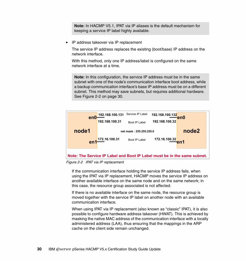
� IP address takeover via IP replacement
The service IP address replaces the existing (boot/base) IP address on the network interface.
With this method, only one IP address/label is configured on the same network interface at a time.
Figure 2-2 IPAT via IP replacement
If the communication interface holding the service IP address fails, when using the IPAT via IP replacement, HACMP moves the service IP address on another available interface on the same node and on the same network; in this case, the resource group associated is not affected.
If there is no available interface on the same node, the resource group is moved together with the service IP label on another node with an available communication interface.
When using IPAT via IP replacement (also known as “classic” IPAT), it is also possible to configure hardware address takeover (HWAT). This is achieved by masking the native MAC address of the communication interface with a locally administered address (LAA), thus ensuring that the mappings in the ARP cache on the client side remain unchanged.
Note: In HACMP V5.1, IPAT via IP aliases is the default mechanism for keeping a service IP label highly available.
Note: In this configuration, the service IP address must be in the same subnet with one of the node’s communication interface boot address, while a backup communication interface’s base IP address must be on a different subnet. This method may save subnets, but requires additional hardware. See Figure 2-2 on page 30.
node1
en0
en1
192.168.100.131
172.16.100.31
192.168.100.31
Service IP Label
Boot IP Label
Boot IP Label
node2
en0
en1
192.168.100.132
172.16.100.32
192.168.100.32
net mask : 255.255.255.0
Note: The Service IP Label and Boot IP Label must be in the same subnet.
30 IBM Eserver pSeries HACMP V5.x Certification Study Guide Update
2.2.6 Planning for network securityPlanning network security is also important to avoid unauthorized access at the cluster nodes.
Starting with HACMP V5.1, a new security mechanism has been introduced, by providing common communication infrastructure (daemon) for all HACMP configuration related communications between nodes.
The introduction of the new cluster communication daemon (clcomdES) provides enhanced security in a HACMP cluster and also speeds up the configuration related operations.
There are three levels of communication security:
� Standard
– Default security level.
– Implemented directly by cluster communication daemon (clcomdES).
– Uses HACMP ODM classes and the /usr/es/sbin/cluster/rhosts file to determine legitimate partners.
� Enhanced
– Used in SP clusters.
– Takes advantage of enhanced authentication method based on third-party authentication method provided by Kerberos.
� Virtual Private Networks (VPN)
– VPNs are configured within AIX.
– HACMP is then configured to use VPNs for all inter-node configuration related communication operations.
By using the cluster secure communication subsystem, HACMP eliminates the need for either /.rhosts files or a Kerberos configuration on each cluster node. However, the /.rhosts may still be needed to support operations for applications that require this remote communication mechanism.
Chapter 2. Planning and design 31

The Cluster Communication Daemon, clcomdES, provides secure remote command execution and HACMP ODM configuration file updates by using the principle of the “least privilege”.
Thus, only the programs found in /usr/es/sbin/cluster/ will run as root; everything else will run as “nobody”. Beside the clcomdES, the following programs are also used:
� cl_rsh is the cluster remote shell execution program.
� clrexec is used to run specific, dangerous commands as root, such as altering files in /etc directory.
� cl_rcp is used to copy AIX configuration files.
These commands are hardcoded in clcomdES and are not supported for running by users.
The cluster communication daemon (clcomdES) has the following characteristics:
� Since cluster communication does not require the standard AIX “r” commands, the dependency on the /.rhosts file has been removed. Thus, even in “standard” security mode, the cluster security has been enhanced.
� Provides reliable caching mechanism for other node’s ODM copies on the local node (the node from which the configuration changes and synchronization are performed).
� Limits the commands which can be executed as root on remote nodes (only the commands in /usr/es/sbin/cluster run as root).
� clcomdES is started from /etc/inittab and is managed by the system resource controller (SRC) subsystem.
� Provides its own heartbeat mechanism, and discovers active cluster nodes (even if cluster manager or RSCT is not running).
Note: Not all cluster communication is secured via clcomdES; other daemons have their own communication mechanism (not based on “r” commands).
� Cluster Manager (clstrmgrES)
� Cluster Lock Daemon (cllockdES)
� Cluster Multi Peer Extension Communication Daemon (clsmuxpdES)
The clcomdES is used for cluster configuration operations such as cluster synchronization, cluster management (C-SPOC), and dynamic reconfiguration (DARE) operations.
32 IBM Eserver pSeries HACMP V5.x Certification Study Guide Update
The clcomdES authentication process for incoming connections is based on checking the node identity against the following files:
� HACMPadapter ODM class (IP labels defined in this class)
� HACMPnode ODM (the IP addresses/labels used as communication path for the nodes in the cluster)
� The /usr/sbin/cluster/etc/rhosts file
Incoming connections are not allowed if the /usr/sbin/cluster/etc/rhosts file is missing or does not contain an entry for the remote initiating node (either IP address or resolvable IP label).
If the HACMPnode, HACMPadapter ODM classes, and the /usr/sbin/cluster/etc/rhosts files are empty, then clcomdES assumes the cluster is being configured and accepts incoming connections, then adds the peer node IP label (address) to the /usr/sbin/cluster/etc/rhosts file, once the initial configuration is completed.
If the IP address requesting connection matches a label in the above locations (HACMPadapter, HACMPnode, and /usr/es/sbin/cluster/etc/rhosts) then clcomdES connects back to the requesting node and asks for the IP label (host name); if the returned IP label (host name) matches the requesting IP address, the authentication is completed successfully.
2.3 HACMP heartbeatAs in many other types of clusters, heartbeating is used to monitor the availability of network interfaces, communication devices, and IP labels (service, non-service, and persistent), and thus the availability of the nodes.
Starting with HACMP V5.1, heartbeating is exclusively based on RSCT topology services (thus HACMP V5.1 is only “Enhanced Scalability”; classic heartbeating with network interface modules (NIMs), monitored directly by the cluster manager daemon, is not used anymore).
Note: ClcomdES provides a transport mechanism for various HACMP services, such as clverify, godm, rsh, and rexec.
Note: If there is an unresolvable label in the /usr/es/sbin/cluster/etc/rhosts file, then all clcomdES connections from remote nodes will be denied.
Chapter 2. Planning and design 33

Heartbeating is performed by exchanging messages (keep alive packets) between the nodes in the cluster over each communication interface or device.
Each cluster node sends heartbeat messages at specific intervals to other cluster nodes, and expects to receive heartbeat messages from the corresponding nodes at specific intervals. If messages stop being received, the RSCT recognizes this as a failure and tells HACMP, which takes the appropriate action for recovery.
The heartbeat messages can be sent over:
� TCP/IP networks� Point to point non-IP networks
To prevent cluster partitioning (split brain), HACMP must be able to distinguish between a node failure and a TCP/IP network failure. TCP/IP network failures can be caused by faulty network elements (switches, hubs, and cables); in this case, the nodes in the cluster are not able to send and receive heartbeat messages (keep alive (KA)) over IP, so each node considers the peers down and will try to acquire the resources. This is a potential data corruption exposure, especially when using concurrent resources.
The non-IP networks are direct connections (point-to-point) between nodes, and do not use IP for heartbeat messages exchange, and are therefore less prone to IP network elements failures. If these network types are used, in case of IP network failure, nodes will still be able to exchange messages, so the decision is to consider the network down and no resource group activity will take place.
To avoid partitioning in an HACMP, we recommend:
� Configure redundant networks (IP and non-IP)� Use both IP and non-IP networks.
For a recommended two-node cluster configuration, see Figure 2-3 on page 35.
34 IBM Eserver pSeries HACMP V5.x Certification Study Guide Update
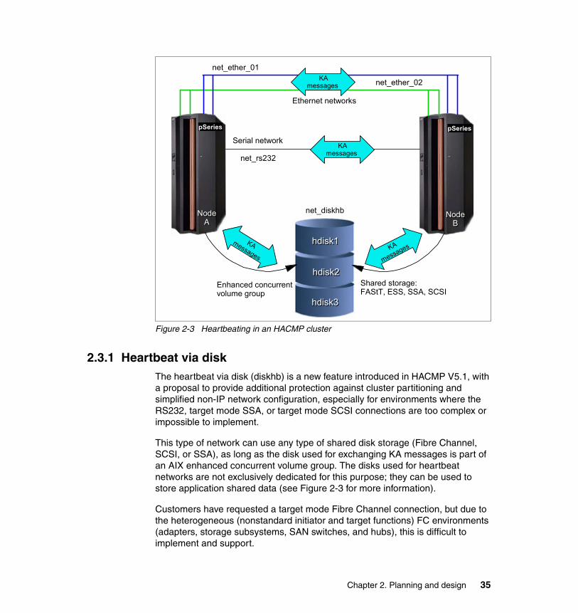
Figure 2-3 Heartbeating in an HACMP cluster
2.3.1 Heartbeat via diskThe heartbeat via disk (diskhb) is a new feature introduced in HACMP V5.1, with a proposal to provide additional protection against cluster partitioning and simplified non-IP network configuration, especially for environments where the RS232, target mode SSA, or target mode SCSI connections are too complex or impossible to implement.
This type of network can use any type of shared disk storage (Fibre Channel, SCSI, or SSA), as long as the disk used for exchanging KA messages is part of an AIX enhanced concurrent volume group. The disks used for heartbeat networks are not exclusively dedicated for this purpose; they can be used to store application shared data (see Figure 2-3 for more information).
Customers have requested a target mode Fibre Channel connection, but due to the heterogeneous (nonstandard initiator and target functions) FC environments (adapters, storage subsystems, SAN switches, and hubs), this is difficult to implement and support.
pSeries
Node Node AA
Ethernet networks
Serial network
net_rs232
Node Node BB
hdisk1hdisk1
hdisk2hdisk2
hdisk3hdisk3
Shared storage:FAStT, ESS, SSA, SCSI
net_ether_01
Enhanced concurrent volume group
net_diskhb
pSeries pSeries
net_ether_02
KA messages
KA messages
KA messages
KA
messages
Chapter 2. Planning and design 35

By using the shared disks for exchanging messages, the implementation of a non-IP network is more reliable, and does not depend of the type of hardware used.
Moreover, in a SAN environment, when using optic fiber to connect devices, the length of this non-IP connection has the same distance limitations as the SAN, thus allowing very long point-to-point networks.
By defining a disk as part of an enhanced concurrent volume group, a portion of the disk will not be used for any LVM operations, and this part of the disk (sector) is used to exchange messages between the two nodes.
The specifications for using the heartbeat via disk are:
� One disk can be used for one network between two nodes. The disk to be used is uniquely identified on both nodes by its LVM assigned physical volume ID (PVID).
� The recommended configuration for disk heartbeat networks is one disk per pair of nodes per storage enclosure.
� Requires that the disk to be used is part of an the enhanced concurrent volume group, though it is not necessary for the volume group to be either active or part of a resource group (concurrent or non-concurrent). The only restriction is that the volume group (VG) must be defined on both nodes.
2.3.2 Heartbeat over IP aliasesFor IP networks, a new heartbeat feature has been introduced: heartbeat over IP aliases. This feature is provided for clusters where changing the base IP addresses of the communication interfaces is not possible or desired.
The IP aliases used for heartbeat are configured on top of existing IP address when HACMP services are started. The IP addresses used for this purpose must be in totally different subnets from the existing ones, and should not be defined for any name resolution (/etc/hosts, BIND, and so on). This configuration does not require any additional routable subnets.
Instead of using the base/boot IP addresses for exchanging heartbeat messages, RSCT uses the HACMP defined IP aliases to establish the communication groups (heartbeat rings) for each communication interface.
Note: The cluster locking mechanism for enhanced concurrent volume groups does not use the reserved disk space for communication (as the “classic” clvmd does); it uses the RSCT group services instead.
36 IBM Eserver pSeries HACMP V5.x Certification Study Guide Update

Even with this technique, HACMP still requires that all the interfaces on a network (from all nodes) be able to communicate with each other (can see each other’s MAC address).
The subnet mask used for IP aliases is the same as the one used for the service IP addresses. When defining the IP address to be used for heartbeat, you have to specify the start address to be used for heartbeating, and must ensure that you have enough subnets available (one per each physical communication interface in a node) that do not conflict with your existent subnets used on the networks.
For example, in a three node cluster were all the nodes have three communication interfaces defined on the same network, you need three non-routable subnets.
Assuming that all nodes have three Ethernet adapters (en0, en1, and en2), netmask class C (255.255.255.0), and the starting IP address to be used for heartbeat over IP aliases is 172.16.100.1, the aliases assigned for each Ethernet adapter (communication interface) will be as shown in Table 2-1. See also Figure 2-4 on page 38 and Figure 2-5 on page 39.
Table 2-1 IP aliases for heartbeat
The addresses used for heartbeat over IP aliases are stored in the HACMPadapter ODM class during the cluster synchronization.
Attention: When using heartbeat over IP aliases, the base/boot IP addresses of the communication interfaces are not monitored by RSCT topology services (and, as a consequence, by HACMP). The communication interfaces are monitored via the assigned IP aliases.
Adapter / Node Node 1 Node 2 Node 3
en0 172.16.100.1 172.16.100.2 172.16.100.3
en1 172.16.101.1 172.16.101.2 172.16.101.3
en2 172.16.102.1 172.16.102.2 172.16.102.3
Chapter 2. Planning and design 37
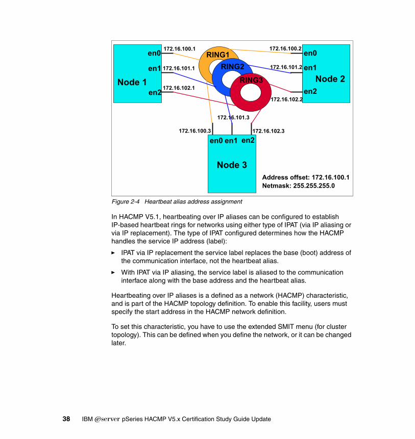
Figure 2-4 Heartbeat alias address assignment
In HACMP V5.1, heartbeating over IP aliases can be configured to establish IP-based heartbeat rings for networks using either type of IPAT (via IP aliasing or via IP replacement). The type of IPAT configured determines how the HACMP handles the service IP address (label):
� IPAT via IP replacement the service label replaces the base (boot) address of the communication interface, not the heartbeat alias.
� With IPAT via IP aliasing, the service label is aliased to the communication interface along with the base address and the heartbeat alias.
Heartbeating over IP aliases is a defined as a network (HACMP) characteristic, and is part of the HACMP topology definition. To enable this facility, users must specify the start address in the HACMP network definition.
To set this characteristic, you have to use the extended SMIT menu (for cluster topology). This can be defined when you define the network, or it can be changed later.
Node 3
en0
en0
en0
en1
en1en1
en2
en2en2
172.16.100.1
172.16.102.3172.16.100.3
172.16.101.3
172.16.102.2
172.16.101.2
172.16.102.1
172.16.101.1
172.16.100.2RING1
RING3
RING2
Address offset: 172.16.100.1Netmask: 255.255.255.0
Node 2Node 1
38 IBM Eserver pSeries HACMP V5.x Certification Study Guide Update

Figure 2-5 IP aliases management
For more information about this topic, refer to Chapter 3, “Planning Cluster Network Connectivity”, in the HACMP for AIX 5L V5.1 Planning and Installation Guide, SC23-4861-02.
2.4 Shared storage configurationMost of the HACMP configurations require shared storage. The IBM disk subsystems that support access from multiple hosts include SCSI, SSA, ESS, and FAStT.
There are also third-party (OEM) storage devices and subsystems that may be used, although most of these are not directly certified by IBM for HACMP usage. For these devices, check the manufacturer’s respective Web sites.
Table 2-2 lists a subset of IBM storage devices (the most commonly used) that can be used for shared access in an HACMP cluster.
Table 2-2 External storage subsystems
172.16.100.1192.168.100.31
172.16.10.31172.16.102.1192.168.11.131
Heartbeat alias (monitored)Boot address (not monitored)
Boot address (not monitored)Heartbeat alias (monitored)Service alias (monitored)
en0en0
en2en2
en1en1172.16.101.1192.168.50.31
Heartbeat alias (monitored)Boot address (not monitored)
pSeries
IBM 7133 SSA Disk Subsystem Models D40 and T40 (up to 72.8 GB disk modules, and up to eight nodes per SSA loop).
IBM Enterprise Storage Server (ESS) Models E10, E20, F10, and F20 (supports up to eight nodes using SCSI and Fibre Channel interfaces via IBM FC/FICON, Feature Code: 3021, 3022, and 3023)
IBM 2105-800 (ESS) Total Storage Enterprise Storage Server (FS and SCSI)
Chapter 2. Planning and design 39

HACMP also supports shared tape drives (SCSI or FC). The shared tape(s) can be connected via SCSI or FC. Concurrent mode tape access is not supported. See Table 2-3 for some of the supported tape subsystems.
Table 2-3 Tape drive support
For an updated list of supported storage and tape drives, check the IBM Web site at:
http://www-1.ibm.com/servers/eserver/pseries/ha/
HACMP may also be configured with non-IBM shared storage subsystems (disk and tape subsystems). For a list of non-IBM storage, refer to the respective manufacturer’s Web sites, and at the Availant Web site:
http://www.availant.com/
2.4.1 Shared LVM requirementsPlanning shared LVM for an HACMP cluster depends on the method of shared disk access and the type of shared disk device. The elements that should be considered for shared LVM are:
� Data protection method� Storage access method� Storage hardware redundancy
IBM Total Storage FAStT 200, 500, 600, 700, and 900 models.
IBM 3583 Ultrium Scalable Tape Library Model L18, L32 and L72
IBM 3584 Ultra™ Scalable Tape Library Model L32 and D32
IBM Total Storage Enterprise Tape Drive 3590 Model H11
IBM Magstar® 3590 Tape Drive Model E11 and B11
IBM 3581 Ultrium Tape Autoloader Model H17 and L17
IBM 3580 Ultrium Tape Drive Model H11 and L11
IBM 7133 SSA Disk Subsystem Models D40 and T40 (up to 72.8 GB disk modules, and up to eight nodes per SSA loop).
Note: HACMP itself does not provide storage protection. Storage protection is provided via:
� AIX (LVM mirroring)� Hardware RAID
40 IBM Eserver pSeries HACMP V5.x Certification Study Guide Update
In this section, we provide information about data protection methods at the storage level, and also talk about the LVM shared disk access modes.
� Non concurrent� Concurrent “classic” (HACMP concurrent logical volume manager - clvm)� Enhanced concurrent mode (ECM), a new option in AIX 5L V5.1 and higher
2.4.2 Non-Concurrent, Enhanced Concurrent, and ConcurrentIn a non-concurrent access configuration, only one cluster node can access the shared data at a time. If the resource group containing the shared disk space moves to another node, the new node will activate the disks, and check the current state of the volume groups, logical volumes, and file systems.
In non-concurrent configurations, the disks can be shared as:
� Raw physical volumes� Raw logical volumes� File systems
In a concurrent access configuration, data on the disks is available to all nodes concurrently. This mode does not support file systems (either JFS or JFS2).
Fast disk takeoverHACMP V5.1 exploits the new AIX enhanced concurrent LVM. In AIX 5L V5.2, any new concurrent volume group must be created in enhanced concurrent mode.
In AIX 5L V5.2 only, the enhanced concurrent volume groups can also be used for file systems (shared or non-shared). This is exploited by the fast disk takeover option to speed up the process of taking over the shared file systems in a fail-over situation.
The enhanced concurrent volume groups are varied on all nodes in the resource group, and the data access is coordinated by HACMP. Only the node that has the resource group active will vary on the volume group in “concurrent active” mode; the other nodes will vary on the volume group in “passive” mode. In “passive” mode, no high level operations are permitted on that volume group.
Attention: When using the resource groups with fast disk takeover option, it is extremely important to have redundant networks and non-IP networks. This will avoid data corruption (after all, the volume groups are in concurrent mode) in a “split brain” situation.
Chapter 2. Planning and design 41

RAID and SSA concurrent modeRAID concurrent mode volume groups are functionally obsolete, since enhanced concurrent mode provides additional capabilities, but RAID concurrent VGs will continue to be supported for some time. Both RAID and SSA concurrent mode volume groups are supported by HACMP V5.1 with some important limitations:
� A concurrent resource group that includes a node running a 64-bit kernel requires enhanced concurrent mode for any volume groups.
� SSA concurrent mode is not supported on 64-bit kernels.
� SSA disks with the 32-bit kernel can still use SSA concurrent mode.
� The C-SPOC utility cannot be used with RAID concurrent volume groups. You have to convert these volume groups to enhanced concurrent mode (otherwise, AIX sees them an non-concurrent).
� In AIX 5L V5.1, it is still possible to create SSA concurrent VGs (with a 32-bit kernel), but in AIX 5L V5.2, it is not possible to create a new HACMP concurrent; all new VGS must be created in enhanced concurrent mode.
LVM requirementsThe Logical Volume Manager (LVM) component of AIX manages the storage by coordinating data mapping between physical and logical storage. Logical storage can be expanded and replicated, and can span multiple physical disks and enclosures.
The main LVM components are:
� Physical volume
A physical volume (PV) represents a single physical disk as it is seen by AIX (hdisk*). The physical volume is partitioned into physical partitions (PPs), which represent the physical allocation units used by LVM.
� Volume group
A volume group (VG) is a set of physical volumes that AIX treats as a contiguous, addressable disk region. In HACMP, the volume group and all its logical volumes can be part of a shared resource group. A volume group cannot be part of multiple resource groups (RGs).
42 IBM Eserver pSeries HACMP V5.x Certification Study Guide Update
� Physical partition
A physical partition (PP) is the allocation unit in a VG. The PVs are divided into PPs (when the PV is added to a VG), and the PPs are used for LVs (one, two, or three PPs per logical partition (LP)).
� Volume group descriptor area (VGDA)
The VGDA is a zone on the disk that contains information about the storage allocation in that volume group.
For a single disk volume group, there are two copies of the VGDA. For a two disk VG, there are three copies of the VGDA: two on one disk and one on the other. For a VG consisting of three or more PVs, there is one VGDA copy on each disk in the volume group.
� Quorum
For an active VG to be maintained as active, a “quorum” of VGDAs must be available (50% + 1). Also, if a VG has the quorum option set to “off”, it cannot be activated (without the “force” option) if one VGDA copy is missing. If the quorum is be turned off, the system administrator must know the mapping of that VG to ensure data integrity.
� Logical volume
A logical volume (LV) is a set of logical partitions that AIX makes available as a single storage entity. The logical volumes can be used as raw storage space or as file system’s storage. In HACMP, a logical volume that is part of a VG is already part of a resource group, and cannot be part of another resource group.
� Logical partition
A logical partition (LP) is the space allocation unit for logical volumes, and is a logical view of a physical partition. With AIX LVM, the logical partitions may be mapped to one, two, or three physical partitions to implement LV mirroring.
� File systems
A file system (FS) is in fact a simple database for storing files and directories. A file system in AIX is stored on a single logical volume. The main components of the file system (JFS or JFS2) are the logical volume that holds the data, the file system log, and the file system device driver. HACMP supports both JFS and JFS2 as shared file systems, with the remark that the
Note: Although LVM mirroring can be used with any type of disk, when using IBM 2105 Enterprise Storage Servers or FAStT storage servers, you may skip this option. These storage subsystems (as well as some non-IBM ones) provide their own data redundancy by using various levels of RAID.
Chapter 2. Planning and design 43

log must be on a separated logical volume (JFS2 also may have inline logs, but this is not supported in HACMP).
Forced varyon of volume groupsHACMP V5.1 provides a new facility, the forced varyon of a volume group option on a node. If, during the takeover process, the normal varyon command fails on that volume group (lack of quorum), HACMP will ensure that at least one valid copy of each logical partition for every logical volume in that VG is available before varying on that VG on the takeover node.
Forcing a volume group to varyon lets you bring and keep a volume group online (as part of a resource group) as long as there is one valid copy of the data available. You should use a forced varyon option only for volume groups that have mirrored logical volumes, and use caution when using this facility to avoid creating a partitioned cluster.
This option is useful in a takeover situation in case a VG that is part of that resource group loses one or mode disks (VGDAs). If this option is not used, the resource group will not be activated on the takeover node, thus rendering the application unavailable.
When using a forced varyon of volume groups option in a takeover situation, HACMP first tries a normal varyonvg. If this attempt fails due to lack of quorum, HACMP checks the integrity of the data to ensure that there is at least one available copy of all data in the volume group before trying to force the volume online. If there is, it runs varyonvg -f; if not, the volume group remains offline and the resource group results in an error state.
For more information see Chapter 5, “Planning Shared LVM Components”, in the HACMP for AIX 5L V5.1 Planning and Installation Guide, SC23-4861-02.
Note: You should specify the super strict allocation policy for the logical volumes in volume groups used with the forced varyon option. In this way, the LVM makes sure that the copies of a logical volume are always on separate disks, and increases the chances that forced varyon will be successful after a failure of one or more disks.
Note: The users can still use quorum buster disks or custom scripts to force varyon a volume group, but the new forced varyon attribute in HACMP automates this action, and customer enforced procedures may now be relaxed.
44 IBM Eserver pSeries HACMP V5.x Certification Study Guide Update

2.4.3 Choosing a disk technologyHACMP V5.1 supports the following storage technologies: SCSI, SSA, and Fibre Channel (like FAStT and ESS disk subsystems). The complete list of supported external storage subsystems (manufactured by IBM) can be found at the following IBM Web site:
http://www-1.ibm.com/servers/eserver/pseries/ha/
HACMP supports the following IBM disk technologies as shared external disks in a highly availability cluster.
IBM 2105 Enterprise Storage ServerIBM 2105 Enterprise Storage Server provides concurrent attachment and disk storage sharing for a variety of open systems servers. Beside IBM Eserver pSeries machines, a variety of other platforms are supported.
Due to the multitude of platforms supported in a shared storage environment, to avoid interference, it is very important to configure secure access to storage by providing appropriate LUN masking and zoning configurations.
The ESS uses IBM SSA disk technology. ESS provides built-in availability and data protection. RAID technology is used to protect data. Also, the disks have intrinsic predictive failure analysis features to predict errors before they affect data availability.
The ESS has virtually all components doubled and provides protection if any internal component fails. The ESS manages the internal storage (SSA disks) with a cluster of two nodes connected through a high speed internal bus, each of the nodes providing the exact same functionality, Thus, in case one of the internal node fails, the storage remains available to the client systems.
For more information about planning and using the 2105-800 Enterprise Storage Server (including attachment diagrams, and more), see the following Web site:
http://www.storage.ibm.com/disk/ess/index.html
An example of a typical HACMP cluster using ESS as shared storage is shown in Figure 2-6 on page 46.
Chapter 2. Planning and design 45
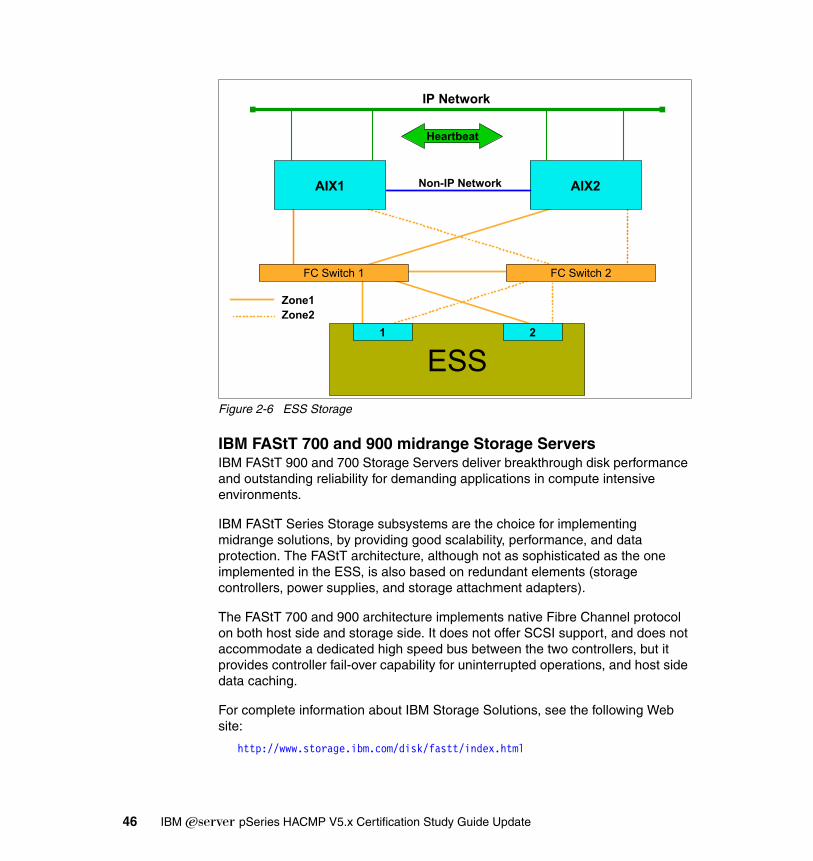
Figure 2-6 ESS Storage
IBM FAStT 700 and 900 midrange Storage ServersIBM FAStT 900 and 700 Storage Servers deliver breakthrough disk performance and outstanding reliability for demanding applications in compute intensive environments.
IBM FAStT Series Storage subsystems are the choice for implementing midrange solutions, by providing good scalability, performance, and data protection. The FAStT architecture, although not as sophisticated as the one implemented in the ESS, is also based on redundant elements (storage controllers, power supplies, and storage attachment adapters).
The FAStT 700 and 900 architecture implements native Fibre Channel protocol on both host side and storage side. It does not offer SCSI support, and does not accommodate a dedicated high speed bus between the two controllers, but it provides controller fail-over capability for uninterrupted operations, and host side data caching.
For complete information about IBM Storage Solutions, see the following Web site:
http://www.storage.ibm.com/disk/fastt/index.html
AIX1 AIX2
FC Switch 1 FC Switch 2
ESS1 2
IP Network
Heartbeat
Non-IP Network
Zone1Zone2
46 IBM Eserver pSeries HACMP V5.x Certification Study Guide Update
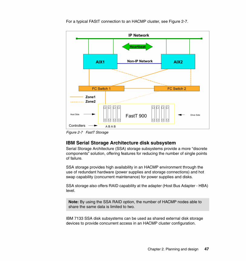
For a typical FAStT connection to an HACMP cluster, see Figure 2-7.
Figure 2-7 FastT Storage
IBM Serial Storage Architecture disk subsystemSerial Storage Architecture (SSA) storage subsystems provide a more “discrete components” solution, offering features for reducing the number of single points of failure.
SSA storage provides high availability in an HACMP environment through the use of redundant hardware (power supplies and storage connections) and hot swap capability (concurrent maintenance) for power supplies and disks.
SSA storage also offers RAID capability at the adapter (Host Bus Adapter - HBA) level.
IBM 7133 SSA disk subsystems can be used as shared external disk storage devices to provide concurrent access in an HACMP cluster configuration.
Note: By using the SSA RAID option, the number of HACMP nodes able to share the same data is limited to two.
AIX1 AIX2
FC Switch 1 FC Switch 2
IP Network
Heartbeat
Non-IP Network
Zone1Zone2
FastT 900
Controllers
Host Side Drive Side
A B A B
Chapter 2. Planning and design 47

SSA storage provides a flexible, fairly simple, more “custom” approach for configuring HACMP clusters with “legacy” or existing applications and a limited number of nodes. We recommend that all new configurations to be implemented use the new technologies (FC storage).
For an example of a two node HACMP cluster, see Figure 2-8.
Figure 2-8 SSA storage
2.5 Software planningIn the process of planning a HACMP cluster, one of the most important steps is to chose the software levels that will be running on the cluster nodes.
The decision factors in node software planning are:
� Operation system requirements: AIX version and recommended levels.
� Application compatibility: Ensure that all requirements for the applications are met, and supported in cluster environments.
� Resources: Types of resources that may be used (IP addresses, storage configuration, if NFS is required, and so on).
Node 1 Node 2
IP Network
Non-IP Network
SSA
Enclosure 1
Enclosure 2
SSA Adapter(s) SSA Adapter(s)
48 IBM Eserver pSeries HACMP V5.x Certification Study Guide Update
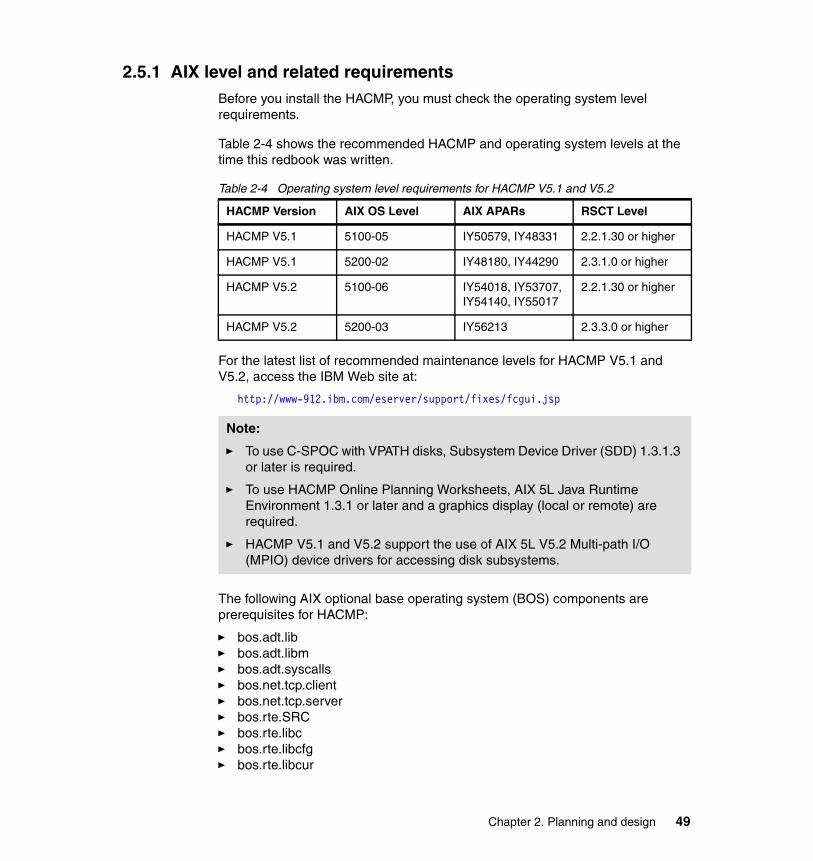
2.5.1 AIX level and related requirementsBefore you install the HACMP, you must check the operating system level requirements.
Table 2-4 shows the recommended HACMP and operating system levels at the time this redbook was written.
Table 2-4 Operating system level requirements for HACMP V5.1 and V5.2
For the latest list of recommended maintenance levels for HACMP V5.1 and V5.2, access the IBM Web site at:
http://www-912.ibm.com/eserver/support/fixes/fcgui.jsp
The following AIX optional base operating system (BOS) components are prerequisites for HACMP:
� bos.adt.lib� bos.adt.libm� bos.adt.syscalls� bos.net.tcp.client� bos.net.tcp.server� bos.rte.SRC� bos.rte.libc� bos.rte.libcfg� bos.rte.libcur
HACMP Version AIX OS Level AIX APARs RSCT Level
HACMP V5.1 5100-05 IY50579, IY48331 2.2.1.30 or higher
HACMP V5.1 5200-02 IY48180, IY44290 2.3.1.0 or higher
HACMP V5.2 5100-06 IY54018, IY53707, IY54140, IY55017
2.2.1.30 or higher
HACMP V5.2 5200-03 IY56213 2.3.3.0 or higher
Note:
� To use C-SPOC with VPATH disks, Subsystem Device Driver (SDD) 1.3.1.3 or later is required.
� To use HACMP Online Planning Worksheets, AIX 5L Java Runtime Environment 1.3.1 or later and a graphics display (local or remote) are required.
� HACMP V5.1 and V5.2 support the use of AIX 5L V5.2 Multi-path I/O (MPIO) device drivers for accessing disk subsystems.
Chapter 2. Planning and design 49

� bos.rte.libpthreads� bos.rte.odm� bos.data
When using the (enhanced) concurrent resource manager access, the following components are also required.
� bos.rte.lvm.5.1.0.25 or higher (for AIX 5L V5.1)� bos.clvm.enh
For the complete list of recommended maintenance levels for AIX 5L V5.1 and V5.2, see the following IBM Web page:
http://www-912.ibm.com/eserver/support/fixes/fcgui.jsp
2.5.2 Application compatibilityHACMP is a flexible, high availability solution, in the sense that virtually any application running on an stand-alone AIX server can be protected through the use of an HACMP cluster.
When starting cluster application planning, you should consider the following aspects:
� Application compatibility with the version of AIX used.
� Application compatibility with the storage method to be implemented for high availability.
� You also must know all the interdependencies between the application and platform, that is, all the locations where all the application files are stored (permanent data, temporary files, sockets, and pipes, if applicable).
� You should be able to provide an unattended application start/stop method (scripts) and the application must be able to recover from errors (for example, in case the node running the application crashes) when restarted.
� If you plan to use application monitoring, you should also provide application monitoring tools (methods, behavior, and scripts).
� Application client dependencies (client behavior when the server is restarted).
� Application network dependencies (sockets, routes, and so on)
� Licensing issues, that is, if your application is dependent on the CPU ID, you should consider purchasing a standby license for each node that can host the
Important: Do not proceed to HACMP implementation if your application does not run correctly on a stand-alone node, or if you are not sure about all application dependencies!!!
50 IBM Eserver pSeries HACMP V5.x Certification Study Guide Update

application. Also, if the application is licensed based on the number of processors, make sure, in a fail-over situation, that the licensing is not breached.
Application serversAccording to the HACMP definition, an application server is represented by a collection of scripts that are used by HACMP to start an application when activating a resource group and to stop the same application when bringing the resource group offline.
Once the application has been started, HACMP can also monitor this application, and take action in case the application does not run properly. The application monitoring can be performed at process level, and also by using a custom method (for example, for a multi-process application like database engines and so on).
HACMP also provides the application availability analysis tool, which is useful for auditing the overall application availability, and for assessing the cluster environment.
For information about application servers and other resources, see 3.5, “Resource group configuration” on page 128.
2.5.3 Planning NFS configurationsOne of the typical applications of HACMP is to provide high availability network file systems (HA-NFS) for client machines and applications. This is useful, especially in a cluster running applications, for mutual takeover with cross-mount network file systems.
Starting with HACMP V4.4, the HA-NFS function has been integrated in HACMP, so there is no separate product anymore.
Some considerations when using NFS:
� For the shared volume groups that will be exported via NFS, the volume group Major Number is the same on all cluster nodes that can serve the file system(s) in that VG.
Note: Application monitoring has been introduced in HACMP/ES V4.4, based on the event management function (EM) of RSCT. Starting with HACMP V5.2, event management has been replaced by Resource Monitoring and Control (RMC), which is functionally equivalent, but provides more flexibility. Starting with HACMP V5.2, it is also possible to monitor application startup.
Chapter 2. Planning and design 51
� In AIX, when you export files and directories, the mknfsexp command is used, so the /etc/exports file is created/updated. In HACMP, on the other hand, the file systems and directories to be exported and NFS mounted must be specified in the resource group configuration.
� If you need any optional configuration for these file systems, you should create the /usr/es/sbin/cluster/etc/exports file.
� For all resource groups that have file systems to export, the “File systems Mounted before IP Address Configured” attribute must be set to “true”.
� The HACMP scripts contain the default NFS behavior. You may need to modify these scripts to handle your particular configuration.
� In HACMP V5.1, in addition to cascading resource groups, you can configure high availability NFS in either in rotating or custom resource groups.
For more information, see the HACMP for AIX 5L V5.1 Planning and Installation Guide, SC23-4861-02.
2.5.4 LicensingMost software vendors require that you have a unique license for each application for each physical machine or per processor in a multi-processor (SMP) machine. Usually, the license activation code is entered at installation time.
However, in a HACMP environment, in a takeover situation, if the application is restarted on a different node, you must make sure that you have the necessary activation codes (licenses) for the new machine; otherwise the application may not start properly.
The application may also require a unique node-bound license (a separate license file on each node).
Some applications also have restrictions with the number of floating licenses available within the cluster for that application. To avoid this problem, be sure that you have enough licenses for each cluster node machine, so the application can run simultaneously on multiple nodes (especially for concurrent applications).
Note: The NFS locking functionality is limited to a cluster with two nodes. This functionality provides a reliable NFS server capability that allows a backup processor to recover current NFS activity should the primary NFS server fail, preserving the locks on NFS file systems and dupcache.
52 IBM Eserver pSeries HACMP V5.x Certification Study Guide Update
2.5.5 Client connectionsDuring resource group takeover, the application is started on another node, so clients must be aware of the action. In certain cases, the applications client uses the ARP cache on the client machine to reconnect to the server. In this case, there are two possible situations:
� The network holding the service IP for that application uses IPAT via IP replacement with locally administered MAC address takeover (thus, the client machine ARP cache does not have to be updated).
� HACMP uses the clinfo program that calls the /usr/es/sbin/cluster/etc/clinfo.rc script whenever a network or node event occurs. By default, this action updates the system’s ARP cache and specified clients ARP cache to reflect changes to network addresses. You can customize this script if further action is desired.
Clients running the clinfo daemon will be able to reconnect to the cluster quickly after a cluster event.
If the HACMP nodes and the clients are on the same subnet, and clients are not running the clinfo daemon, you may have to update the local ARP cache indirectly by pinging the client from the cluster node.
You can achieve this by adding, on the cluster nodes, the IP labels or IP addresses of the client hosts you want to notify to the PING_CLIENT_LIST variable in the clinfo.rc script. Whenever a cluster event occurs, the clinfo.rc scripts executes the following command for each host specified in PING_CLIENT_LIST:
# ping -c1 $host
In case the clients are on a different subnet, make sure that the router ARP cache is updated when an IPAT occurs; otherwise, the clients will expect delays in reconnecting.
2.6 Operating system space requirementsIn HACMP V5.1, both the cluster verification program (clverify) and the new cluster communication daemon (clcomdES) need additional space in the /var file system.
Note: If you are using IPAT via IP Aliases, make sure all your clients support TCP/IP gratuitous ARP functionality.
Chapter 2. Planning and design 53

Due to verbose messaging and additional debugging information, the following requirements must be satisfied for the free space in the /var file system on every node in the cluster:
� 20 MB, times 1, where:
– /var/hacmp/clcomd/clcomd.log requires 2 MB.
– /var/hacmp/clcomd/clcomddiag.log requires 18 MB.
� Additional (1 MB x number of nodes in the cluster) space for the files stored in /var/hacmp/odmcache directory.
� 4 MB for each cluster node for cluster verification data.
� 2 MB for the cluster verification log (clverify.log[0-9]).
For example, for a four-node cluster, we recommend that you have at least 42 MB of free space in the /var file system, where:
� 2 MB should be free for writing the clverify.log[0-9] files.
� 16 MB (4 MB per node) should be free for writing the verification data from the nodes.
� 20 MB should be free for writing the clcomd log information.
� 4 MB (1 MB per node) should be free for writing the ODM cache data.
For each node in the cluster, the clverify utility requires up to 4 MB of free space in the /var file system. The clverify can keep up to four different copies of a node's verification data at a time (on the node that has initiated the verification):
� /var/hacmp/clverify/current/<nodename>/* contains logs from a current execution of clverify.
� /var/hacmp/clverify/pass/<nodename>/* contains logs from the last passed verification.
� /var/hacmp/clverify/pass.prev/<nodename>/* contains logs from the second last passed verification.
� /var/hacmp/clverify/fail/<nodename>/* contains information about the last failed verification process.
Also, the /var/hacmp/clverify/clverify.log and its copies [0-9] typically consume 1-2 MB of disk space.
2.7 Resource group planningA resource group is a logical entity containing the resources to be made highly available by HACMP. The resources can be:
54 IBM Eserver pSeries HACMP V5.x Certification Study Guide Update
� Storage space (application code and data)
– File systems– Network File Systems– Raw logical volumes– Raw physical disks
� Service IP addresses/labels (used by the clients to access application data)
� Application servers
– Application start script– Application stop script
To be made highly available by the HACMP, each resource must be included in a resource group.
HACMP ensures the availability of cluster resources by moving resource groups from one node to another whenever a cluster event occurs and conditions in the cluster change.
HACMP controls the behavior of the resource groups in the following situations:
� Cluster startup� Node failure� Node reintegration� Cluster shutdown
During each of these cluster stages, the behavior of resource groups in HACMP is defined by:
� Which node, or nodes, acquire the resource group at cluster startup.
� Which node takes over the resource group when the owner node fails.
� Whether a resource group falls back to the node that has just recovered from a failure that occurred earlier, or stays on the node that currently owns it.
The priority relationships among cluster nodes determines which cluster node originally controls a resource group and which node takes over control of that resource group when the original node re-joins the cluster after a failure.
Chapter 2. Planning and design 55

The resource groups takeover relationship can be defined as:
� Cascading� Rotating� Concurrent� Custom
The cascading, rotating and concurrent resource groups are the “classic”, pre- HACMP V5.1 types. Since the definition of these types may be difficult to understand, the new “custom” type of resource group has been introduced in HACMP V5.1.
This is just one step in normalizing HACMP terminology and making HACMP concepts easier to understand. Starting with HACMP V5.2, the “classic” resource group types have been replaced by custom only resource groups.
2.7.1 Cascading resource groupsA cascading resource group defines a list of all the nodes that can control the resource group and each node’s priority in taking over the resource group.
A cascading resource group behavior is as follows:
� At cluster startup, a cascading resource group is activated on its home node by default (the node with the highest priority in the node group).
In addition, another attribute named “Inactive Takeover” may be used to specify that the resource group can be activated on a lower priority node if the highest priority node (also known as the home node) is not available at cluster startup.
� Upon node failure, a cascading resource group falls over to the available node with the next priority in the RG node priority list.
In addition, by specifying a “Dynamic Node Priority” policy for a resource group, the fail over process will determine the node that will take over that resource group based on some dynamic parameters (the node with the highest CPU free, for example).
� Upon node reintegration into the cluster, a cascading resource group falls back to its home node by default.
In addition, by specifying the “Cascading without Fallback” attribute for the resource group, the resource group will remain on the takeover node even if a node with a higher priority becomes available.
56 IBM Eserver pSeries HACMP V5.x Certification Study Guide Update

To summarize, cascading resource groups have the following attributes:
� Inactive Takeover (IT) is an attribute that allows you to fine-tune the startup (initial acquisition) of a resource group in case the home node is not available.
� When a failure occurs on a node that currently owns one of these groups, the group will fall over to the next available in the node priority list. The fall-over priority can be configured in one of two ways: using the default node priority list (which is the order the nodes are listed when configuring the RG), or by setting a Dynamic Node Priority (DNP) policy.
� Cascading without Fallback (CWOF) is an attribute that modifies the fall-back behavior. By using the CWOF attribute, you can avoid unnecessary RG fallback (thus client interruption) whenever a node with a higher priority becomes available. In this mode, you can move the RG to its home node manually at a convenient time, without disturbing the clients.
2.7.2 Rotating resource groupsFor a rotating resource group, the node priority list only determines which node will take over the resource group, in case the owner node fails.
At cluster startup, the first available node in the node priority list will activate the resource group.
If the resource group is on the takeover node, it will never fall back to a higher priority node if one becomes available.
There is no Dynamic Node Priority (DNP) calculation for rotating RGs.
When configuring multiple rotating RGs over the same node set in order to control the preferred location of rotating resource groups, each group should be assigned a different highest priority node from the list of participating nodes. When the cluster starts, each node will attempt to acquire the rotating resource group for which it is the highest priority.
If all rotating resource groups are up, new nodes joining the cluster will join only as backup nodes for these resource groups. If all rotating groups are not up, a node joining the cluster will generally acquire only one of these inactive resource groups.The remaining resource groups will stay inactive.
However, if multiple networks exist on which the resource groups can move, a node may acquire multiple rotating groups, one per network.
Chapter 2. Planning and design 57
2.7.3 Concurrent resource groupsAs the name suggests, a concurrent RG can be active on multiple nodes at the same time. At cluster startup, the RG will be activated on all nodes in the list, in no preferred startup order.
For concurrent resource groups, there is no priority among the nodes; they are all equal owner-nodes. If one node fails, the other nodes continue to offer the service; the group does not move.
Additional concurrent software may be required to manage concurrent access to application data.
2.7.4 Custom resource groupsThis new RG type has been introduced in HACMP V5.1 to simplify resource group management and understanding. The resource group designations (cascading, rotating, and concurrent) can be confusing for new users, because:
� They do not clearly indicate the underlying RG behaviors.
� Additional RG parameters can further complicate the RG definition: Cascading without Fallback and Inactive Takeover.
Also, in some cases, users require combinations of behaviors that are not provided by the standard RG definitions.
� HACMP V5.1 introduces Custom Resource Groups.
– Users have to explicitly specify the desired startup, fall-over, and fall-back behaviors.
– RG Startup and Fallback can be controlled through the use of Settling and Fallback Timers.
– RG Fallover can also be influenced through the use of Dynamic Node Priority (DNP).
� Limitations (HACMP V5.1 only):
– Custom RGs support only IPAT-via-Aliasing service IP addresses/labels.
– There is no site or replicated resource support (for HACMP-XD).
Startup preferences � Online On Home Node Only: At node startup, the RG will only be brought
online on the highest priority node. This behavior is equivalent to cascading RG behavior.
� Online On First Available Node: At node startup, the RG will be brought online on the first node activated. This behavior is equivalent to that of a rotating RG
58 IBM Eserver pSeries HACMP V5.x Certification Study Guide Update
or a cascading RG with inactive takeover. If a settling time is configured, it will affect RGs with this behavior.
� Online On All Available Nodes: The RG should be online on all nodes in the RG. This behavior is equivalent to concurrent RG behavior. This startup preference will override certain fall-over and fall-back preferences.
Fallover preferences � Fallover To Next Priority Node In The List: The RG will fall over to the next
available node in the node list. This behavior is equivalent to that of cascading and rotating RGs.
� Fallover Using Dynamic Node Priority: The RG will fall over based on DNP calculations. The resource group must specify a DNP policy.
� Bring Offline (On Error Node Only): The RG will not fall over on error; it will simply be brought offline. This behavior is most appropriate for concurrent-like RGs.
Fallback preferences � Fallback To Higher Priority Node: The RG will fall back to a higher priority
node if one becomes available. This behavior is equivalent to cascading RG behavior. A fall-back timer will influence this behavior.
� Never Fallback: The resource group will stay where it is, even if a higher priority node comes online. This behavior is equivalent to rotating RG behavior.
2.7.5 Application monitoringIn addition to resource group management, HACMP can also monitor applications in one of the following two ways:
� Application process monitoring: Detects the death of a process, using RSCT event management capability.
� Application custom monitoring: Monitors the health of an application based on a monitoring method (program or script) that you define.
Note: You cannot use application process monitoring for applications launched via a shell script, or for applications where monitoring just the process may not be relevant for application sanity.
For monitoring shell script applications, you have to use custom monitoring methods (for example, Apache Web server).
Chapter 2. Planning and design 59

When application monitoring is active, HACMP behaves as follows:
� For application process monitoring, a kernel hook informs the HACMP cluster manager that the monitored process has died, and HACMP initiates the application recovery process.
For the recovery action to take place, you must provide a method to clean up and restart the application (the application start/stop scripts provided for the application server definition may be used).
HACMP tries to restart the application and waits for the application to stabilize a specified number of times, before sending an notification message and/or actually moving the entire RG to a different node (next node in the node priority list).
� For custom application monitoring (custom method), beside the application cleanup and restart methods, you must also provide a program/script to be used for performing periodic application tests.
To plan the configuration of a process monitor, check the following:
� Verify whether this application can be monitored with a process monitor.
� Check the name(s) of the process(es) to be monitored. It is mandatory to use the exact process names to configure the application monitor.
� Specify the user name that owns of the processes, for example, root. Note that the process owner must own all processes to be monitored.
� Specify the number of instances of the application to monitor (number of processes). The default is one instance.
� Specify the time (in seconds) to wait before beginning monitoring.
� The restart count, denoting the number of times to attempt to restart the application before taking any other actions.
� The interval (in seconds) that the application must remain stable before resetting the restart count.
� The action to be taken if the application cannot be restarted within the restart count. The default choice is notify, which runs an event to inform the cluster of the failure. You can also specify fallover, in which case the resource group containing the failed application moves over to the cluster node with the next-highest priority for that resource group.
� The restart method, if desired. (This is required if “Restart Count” is not zero.)
Note: In most circumstances, this value should not be zero. For example, with a database application, you may want to delay monitoring until after the start script and initial database search have been completed.
60 IBM Eserver pSeries HACMP V5.x Certification Study Guide Update

If you plan to set up a custom monitor method, also check:
� Whether you have specified a program/script to be used for checking the specified application.
� The polling interval (in seconds) for how often the monitor method is to be run. If the monitor does not respond within this interval, the application is considered in error and the recovery process is started.
� The signal to kill the user-defined monitor method if it does not return within the polling interval. The default is SIGKILL.
� The time (in seconds) to wait before beginning monitoring. For example, with a database application, we recommend that you delay monitoring until after the start script and initial database search has been completed (otherwise, the application may be considered in an error state and the recovery process will be initiated).
� The restart count, that is the number of times to attempt to restart the application before taking any other actions.
� The interval (in seconds) that the application must remain stable before resetting the restart count.
� The action to be taken if the application cannot be restarted within the restart count.
For more information, see the HACMP for AIX 5L V5.1 Planning and Installation Guide, SC23-4861-02.
2.8 Disaster recovery planningStarting with HACMP V5.1, HAGEO and GeoRM have been integrated into HACMP as the IBM HACMP/XD (extended distance) feature.
HAGEO software product provides a flexible, reliable platform for building disaster-tolerant computing environments. HAGEO components can mirror data across TCP/IP point-to-point networks over an unlimited distance from one geographic site to another.
HAGEO works with HACMP to provide automatic detection, notification, and recovery of an entire geographic site from failures.
Chapter 2. Planning and design 61

The disaster recovery strategies discussed in this book use two sites: the original and the recovery or backup site. Data recovery strategies must address the following issues:
� Data readiness levels.
– Level 0: None. No provision for disaster recovery.
– Level 1: Periodic backup. Data required for recovery up to a given date is backed up and sent to another location.
– Level 2: Ready to roll forward. In addition to periodic backups, data update logs are also sent to another location. Transport can be manual or electronic. Recovery is to the last log data set stored at the recovery site.
– Level 3: Roll forward or forward recover. A shadow copy of the data is maintained on disks at the recovery site. Data update logs are received and periodically applied to the shadow copy using recovery utilities.
– Level 4: Real time roll forward. Like roll forward, except updates are transmitted and applied at the same time as they are being logged in the original site. This real-time transmission and application of log data does not impact transaction response time at the original site.
– Level 5: Real time remote update. Both the original and the recovery copies of data are updated before sending the transaction response or completing a task.
� Site interconnection options.
– Level 0: None. There is no interconnection or transport of data between sites.
– Level 1: Manual transport. There is no interconnection. For transport of data between sites, dispatch, tracking, and receipt of data is managed manually.
– Level 2: Remote tape. Data is transported electronically to a remote tape. Dispatch and receipt are automatic. Tracking can be either automatic or manual.
– Level 3: Remote disk. Data is transported electronically to a remote disk. Dispatch, receipt, and tracking are all automatic.
� Recovery site readiness.
– Cold: A cold site typically is an environment with the proper infrastructure, but little or no data processing equipment. This equipment must be installed as the first step in the data recovery process.
Both periodic backup and ready to roll forward data can be shipped from a storage location to this site when a disaster occurs.
62 IBM Eserver pSeries HACMP V5.x Certification Study Guide Update

– Warm: A warm site has data processing equipment installed and operational. This equipment is used for other data processing tasks until a disaster occurs. Data processing resources can be used to store data, such as logs. Recovery begins after the regular work of the site is shut down and backed up.
Both periodic backup and ready to roll forward data can be stored at this site to expedite disaster recovery.
– Hot: A hot site has data processing equipment installed and operational and data can be restored either continually or regularly to reduce recovery time.
All levels from roll forward to real-time remote update can be implemented.
HAGEO software provides the highest level of disaster recovery:
� Level 5: HAGEO provides real-time remote update data readiness by updating both the original and the recovery copies of data prior to sending a transaction response or completing a task.
� Level 3: HAGEO also provides remote disk site interconnectivity by transmitting data electronically to a geographically distant site where the disks are updated and all bookkeeping is automatic.
� HAGEO provides hot site readiness. Since recovery site contains operational data processing equipment along with current data, this keeps recovery time to a minimum.
Moreover, with HAGEO, the recovery site can be actively processing data and performing useful work. In fact, each site can be a backup for the other, thereby minimizing the cost of setting up a recovery site for each original production site.
HACMP contribution to disaster recoveryThe HACMP base software lays the foundation of the loosely coupled clustering technology to prevent individual system components like processors, networks, and network adapters from being single points of failure within a cluster. This software ensures that the computing environment within a site remains highly available.
You just have to define the system components within your site in terms of HACMP cluster components, and the HACMP base software facilities help keep the system components highly available within that site.
For more information, see the High Availability Clusters Multi-Processing XD (Extended Distance) for HAGEO Technology: Planning and Administration Guide, SA22-7956.
Chapter 2. Planning and design 63
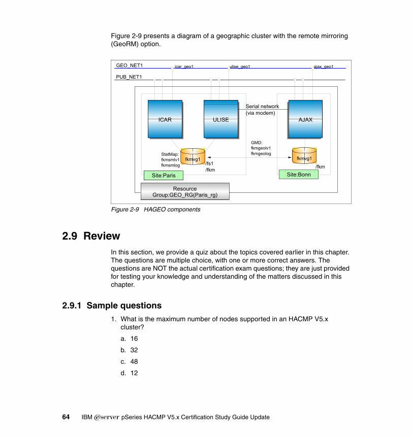
Figure 2-9 presents a diagram of a geographic cluster with the remote mirroring (GeoRM) option.
Figure 2-9 HAGEO components
2.9 ReviewIn this section, we provide a quiz about the topics covered earlier in this chapter. The questions are multiple choice, with one or more correct answers. The questions are NOT the actual certification exam questions; they are just provided for testing your knowledge and understanding of the matters discussed in this chapter.
2.9.1 Sample questions1. What is the maximum number of nodes supported in an HACMP V5.x
cluster?
a. 16
b. 32
c. 48
d. 12
GEO_NET1
GMD:fkmgeolv1fkmgeolog
PUB_NET1
icar_geo1 ulise_geo1 ajax_geo1
/fs1/fkm /fkm
StatMap:fkmsmlv1fkmsmlog
fkmvg1
AJAX
fkmvg1
ULISEICAR
Site:ParisSite:Paris Site:Bonn
Resource Group:GEO_RG(Paris_rg)
Serial network(via modem)
64 IBM Eserver pSeries HACMP V5.x Certification Study Guide Update

2. Which are the most important characteristics of an AIX node to be considered while sizing the cluster?
a. CPU, amount of internal memory, amount of internal storage, and number of PCI I/O slots
b. CPU, amount of internal memory, number of power supplies, and size of internal storage
c. CPU, amount of internal memory, number of I/O slots, and type of external storage
d. CPU, amount of internal memory, type of external storage, and number of fans
3. Which are the most important characteristics to be consider while planning cluster shared storage?
a. Number of disks and power supplies
b. Number of nodes supported for shared access and data protection technology (RAID, JBOD, and so on)
c. Number of nodes and disks supported
4. What is the purpose of the non-IP network in an HACMP V5.x cluster?
a. To help avoid a data corruption in case of IP network failure
b. Client access
c. Service network
d. Exchange heartbeat message
5. What is the definition of “communication interface” in HACMP V5.x?
a. An end of a point to point serial connection
b. A network interface capable of communicating via IP protocol
c. One physical interface used to provide node to node communication
6. What is the meaning of “IP alias” in HACMP V5.x?
a. A name of a communication interface
b. An IP address added to a communication interface on top of existing IP address(es)
c. An alternate hardware address
Chapter 2. Planning and design 65

7. How many persistent IP labels/addresses can be configured for each node in an HACMP cluster?
a. One per node per network
b. Two
c. Four
d. Eight
8. Select one non-supported type of non-IP network in HACMP V5.x:
a. RS232
b. Target mode SSA
c. 802_ether
d. Disk heartbeat
9. Which IP address takeover method requires that the service IP address(es) be in a different subnet from any of the boot IP addresses of the node’s communication interfaces?
a. IPAT via replacement
b. IPAT via aliasing with heartbeat over IP aliases
c. Hardware address takeover
d. IPAT via aliasing
10.Which is the default takeover mechanism used by HACMP V5.x for service IP addresses?
a. IPAT via replacement
b. IPAT via aliasing
c. Hardware address takeover
d. Heartbeat over IP aliases
11.Which is the default authentication mechanism for configuring HACMP V5.x cluster communication?
a. Standard
b. VPN
c. Enhanced
d. Kerberos V4
66 IBM Eserver pSeries HACMP V5.x Certification Study Guide Update

12.What is the name of new cluster communication daemon?
a. clinfoES
b. clstmgrES
c. cllockdES
d. clcomdES
13.Which base operating system (AIX) file is updated to provide automatic start for the cluster communication daemon?
a. /etc/hosts
b. /etc/services
c. /etc/rc.net
d. /etc/inittab
14.What type of volume group is used for disk heartbeat networks?
a. Concurrent
b. Non-concurrent
c. Enhanced concurrent
d. Shared concurrent
15.How many disks are required to configure the heartbeat over disk network between two cluster nodes?
a. Two
b. Three
c. One
d. One disk per pair of nodes, per enclosure
16.How many nodes can be connected (configured) on a single heartbeat over disk network?
a. Two
b. Three
c. Five
d. All cluster nodes
Chapter 2. Planning and design 67

17.Which filesets are required to be installed for using the concurrent resource manager with enhanced concurrent VGs?
a. bos.lvm and cluster.es.clvm
b. bos.clvm.enh and cluster.es.lvm
c. bos.clvm.enh and cluster.es.clvm
d. All of the above
18.When configuring the resource group attributes via SMIT, which option must be set to True to guarantee that IP address takeover will be performed after exporting the file systems part of that resource group?
a. File systems mounted after IP address configured
b. File systems mounted before IP configured
c. File systems automatically mounted
d. NFS hard mount
19.What is the amount of storage space required in the /var file system to accommodate HACMP dynamic reconfiguration (DARE) operation logs?
a. 10 MB
b. 4 MB per cluster node
c. 20 MB
d. 1 MB per cluster node
20.What is the new type of resource group type that provides for configuring settling timers?
a. Cascading
b. Rotating
c. Concurrent
d. Custom
21.Which IPAT method is supported for custom resource groups in HACMP V5.1?
a. IPAT via replacement
b. IPAT via aliasing
c. Hardware address takeover
d. Heartbeat over disk network
Answers to the quiz can be found in Appendix A, “ITSO sample cluster” on page 285.
68 IBM Eserver pSeries HACMP V5.x Certification Study Guide Update
Chapter 3. Installation and configuration
In this chapter, we cover some of the basic HACMP installation issues and various installation procedures. The topics covered in this chapter are:
� HACMP software installation
� Network configuration
� Storage configuration
� HACMP cluster configuration
– Topology configuration– Resource configuration (standard)– Custom resource configuration
Note: Planning is one half of a successful implementation, but when it comes to HACMP, we cannot emphasize enough that proper planning is needed. If planning is not done properly, you may find yourself entangled in restrictions at a later point, and recovering from these restrictions can be a painful experience. So take your time and use the planning worksheets that comes with the product; they are invaluable in any migration or problem determination situations or for documenting the plan.
3
© Copyright IBM Corp. 2004, 2006. All rights reserved. 69
3.1 HACMP software installationThe HACMP software provides a series of facilities that you can use to make your applications highly available. You must keep in mind that not all system or application components are protected by HACMP.
For example, if all the data for a critical application resides on a single disk, and that specific disk fails, then that disk is a single point of failure for the entire cluster, and is not protected by HACMP. AIX logical volume manager or storage subsystems protection must be used in this case. HACMP only provides takeover for the disk on the backup node, to make the data available for use.
This is why HACMP planning is so important, because your major goal throughout the planning process is to eliminate single points of failure. A single point of failure exists when a critical cluster function is provided by a single component. If that component fails, the cluster has no other way of providing that function, and the application or service dependent on that component becomes unavailable.
Also keep in mind that a well-planned cluster is easy to install, provides higher application availability, performs as expected, and requires less maintenance than a poorly planned cluster.
3.1.1 Checking for prerequisitesOnce you have finished your planning working sheets, verify that your system meets the requirements that are required by HACMP; many potential errors can be eliminated if you make this extra effort.
HACMP V5.1 requires one of the following operating system components:
� AIX 5L V5.1 ML5 with RSCT V2.2.1.30 or higher.
� AIX 5L V5.2 ML2 with RSCT V2.3.1.0 or higher (recommended 2.3.1.1).
� C-SPOC vpath support requires SDD 1.3.1.3 or higher.
For the latest information about prerequisites and APARs, refer to the README file that comes with the product and the following IBM Web page:
http://techsupport.services.ibm.com/server/cluster/
70 IBM Eserver pSeries HACMP V5.x Certification Study Guide Update
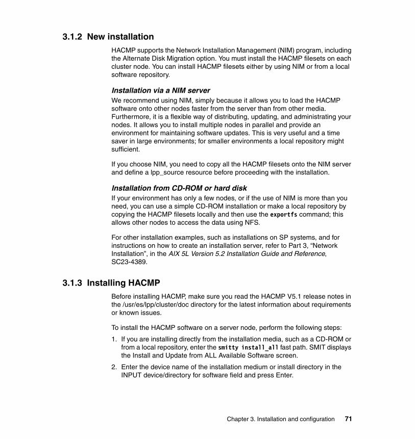
3.1.2 New installationHACMP supports the Network Installation Management (NIM) program, including the Alternate Disk Migration option. You must install the HACMP filesets on each cluster node. You can install HACMP filesets either by using NIM or from a local software repository.
Installation via a NIM serverWe recommend using NIM, simply because it allows you to load the HACMP software onto other nodes faster from the server than from other media. Furthermore, it is a flexible way of distributing, updating, and administrating your nodes. It allows you to install multiple nodes in parallel and provide an environment for maintaining software updates. This is very useful and a time saver in large environments; for smaller environments a local repository might sufficient.
If you choose NIM, you need to copy all the HACMP filesets onto the NIM server and define a lpp_source resource before proceeding with the installation.
Installation from CD-ROM or hard diskIf your environment has only a few nodes, or if the use of NIM is more than you need, you can use a simple CD-ROM installation or make a local repository by copying the HACMP filesets locally and then use the exportfs command; this allows other nodes to access the data using NFS.
For other installation examples, such as installations on SP systems, and for instructions on how to create an installation server, refer to Part 3, “Network Installation”, in the AIX 5L Version 5.2 Installation Guide and Reference, SC23-4389.
3.1.3 Installing HACMPBefore installing HACMP, make sure you read the HACMP V5.1 release notes in the /usr/es/lpp/cluster/doc directory for the latest information about requirements or known issues.
To install the HACMP software on a server node, perform the following steps:
1. If you are installing directly from the installation media, such as a CD-ROM or from a local repository, enter the smitty install_all fast path. SMIT displays the Install and Update from ALL Available Software screen.
2. Enter the device name of the installation medium or install directory in the INPUT device/directory for software field and press Enter.
Chapter 3. Installation and configuration 71

3. Enter the corresponding field values.
To select the software to install, press F4 for a software listing, or enter all to install all server and client images. Select the packages you want to install according to your cluster configuration. Some of the packages may require prerequisites that are not available in your environment (for example, Tivoli Monitoring).
The cluster.es and cluster.cspoc images (which contain the HACMP run-time executable) are required and must be installed on all servers.
Make sure you select Yes in the Accept new license agreements field. You must choose Yes for this item to proceed with installation. If you choose No, the installation may stop with a warning that one or more filesets require the software license agreements. You accept the license agreement only once for each node.
4. Press Enter to start the installation process.
Post-installation stepsTo complete the installation after the HACMP software is installed, perform the following steps:
1. Verify the software installation by using the AIX command lppchk, and check the installed directories to see if the expected files are present.
2. Run the commands lppchk -v and lppchk -c cluster*. Both commands run clean if the installation is OK; if not, use the proper problem determination techniques to fix any problems.
3. Although not mandatory, we recommend you reboot each cluster node in your HACMP environment.
If you do not want to reboot, make sure you start the cluster communication daemon (clcomdES) on all cluster nodes with the following command:
# startsrc -s clcomdES
3.1.4 Migration paths and optionsIf you are in the process of upgrading or converting your HACMP cluster, the following options are available: node-by-node migration and snapshot conversion.
Note: If you are installing the Concurrent Resource Manager feature, you must install the cluster.es.clvm LPPs, and if you choose cluster.es and cluster.cspoc, you must also select the associated message packages.
72 IBM Eserver pSeries HACMP V5.x Certification Study Guide Update

Node-by-node migrationThe node-by-node migration path is used if you need to maintain the application available during the migration process. The steps for a node-by-node migration are:
1. Stop the cluster services on one cluster node.
2. Upgrade the HACMP software.
3. Reintegrate the node into the cluster again.
This process has also been referred to as “rolling migration”. This migration option has certain restrictions; for more details, see 3.1.6, “Node-by-node migration” on page 77.
If you can afford a maintenance window for the application, the steps for migration are:
1. Stop cluster services on all cluster nodes.
2. Upgrade the HACMP software on each node.
3. Start cluster services on one node at a time.
Snapshot migrationYou can also convert the entire cluster to HACMP V5.1 by using a cluster snapshot facility. However, the cluster will be unavailable during the entire process, and all nodes must be upgraded before the cluster is activated again. For more details, see 3.1.5, “Converting a cluster snapshot” on page 73.
3.1.5 Converting a cluster snapshotThis migration method has been provided for cases where both AIX and HACMP must be upgraded/migrated at once (for example, AIX V4.3.3 and HACMP V4.4.1 to AIX 5L V5.1 and HACMP V5.1).
If you are migrating from an earlier supported version of HACMP (HAS) to HACMP V5.x, you can migrate the cluster without taking a snapshot. Save the planning worksheet and configuration files from the current configuration for future reference if you want to configure the HACMP cluster in the same way as it was configured in the previous installation. Uninstall the HACMP software components, reinstall them with the latest HACMP version, and configure them according to the saved planning and configuration files.
Important: It is very important that you do not leave your cluster in a mixed versions state for longer periods of time, since high availability cannot be guaranteed.
Chapter 3. Installation and configuration 73
To convert from a supported version of HAS to HACMP, perform the following steps:
1. Make sure that the current software is committed (not in applied status).
2. Save your HAS cluster configuration in a snapshot and save any customized event scripts you want to retain.
3. Remove the HAS software on all nodes in the cluster.
4. Install the HACMP V5.1 software.
5. Verify the installed software.
6. Convert and apply the saved snapshot.
The cluster snapshot utility allows you to save the cluster configuration to a file by doing the following steps:
1. Reinstall any saved customized event scripts, if needed.
2. Reboot each node.
3. Synchronize and verify the HACMP V5.1 configuration.
The following sections explain each of these steps.
Check for previous HACMP versions To see if HACMP Classic (HAS) software exists on your system, enter the following command:
# lslpp -h “cluster*”
If the output of the lslpp command reveals that HACMP is installed, but is less than V4.5, you must upgrade to V4.5 at a minimum before continuing with the snapshot conversion utility. For more information, refer to the HACMP for AIX 5L V5.1 Administration and Troubleshooting Guide, SC23-4862-02.
Saving your cluster configuration and customized event scriptsTo save your HACMP (HAS) (V4.5 or greater) cluster configuration, create a snapshot in HACMP (HAS). If you have customized event scripts, they must also be saved.
Note: You should be aware that after a migration or upgrade, none of the new HACMP V5.x features are active. To activate the new features (enhancements), you need to configure the options and synchronize the cluster.
74 IBM Eserver pSeries HACMP V5.x Certification Study Guide Update

How to remove the HACMP (HAS) softwareTo remove the HACMP software and your cluster configuration on cluster nodes and clients, perform the following steps:
1. Enter the smitty install_remove fast path. You should get the screen shown in Example 3-1.
Example 3-1 Remove installed software
Remove Installed Software
Type or select values in entry fields.Press Enter AFTER making all desired changes.
[Entry Fields]* SOFTWARE name [cluster*] + PREVIEW only? (remove operation will NOT occur) yes + REMOVE dependent software? no + EXTEND file systems if space needed? no + DETAILED output? no +
F1=Help F2=Refresh F3=Cancel F4=ListF5=Reset F6=Command F7=Edit F8=ImageF9=Shell F10=Exit Enter=Do
Installing HACMP V5.1Follow the instructions for installing the HACMP software in 3.1.3, “Installing HACMP” on page 71.
Verify the installed softwareAfter installing HACMP, verify that the expected files are there using lppchk. For more information, see “Post-installation steps” on page 72.
Convert and apply the saved snapshotAfter you have installed HACMP V5.1 on the cluster nodes, you need to convert and apply the snapshot you saved from your previous configuration.
Attention: Do not save your cluster configuration or customized event scripts in any of the following directory paths /usr/sbin/cluster, /usr/es/sbin/cluster, or /usr/lpp/cluster. These directories are deleted and recreated during the installation of new HACMP packages.
Note: Do not reboot until you have converted and applied the saved snapshot.
Chapter 3. Installation and configuration 75

To convert and apply the saved snapshot:
1. Use the clconvert_snapshot utility, specifying the HACMP (HAS) version number and snapshot file name to be converted. The -C flag converts an HACMP (HAS) snapshot to an HACMP V5.1 snapshot format:
clconvert_snapshot -C -v version -s <filename>
2. Apply the snapshot.
Reinstall saved customized event scriptsReinstall any customized event scripts that you saved from your previous configuration.
Reboot cluster nodesRebooting the cluster nodes is necessary to activate the new cluster communication daemon (clcomdES).
Verify and synchronize the cluster configurationAfter applying the HACMP software and rebooting each node, you must verify and synchronize the cluster topology. Verification provides errors and/or warnings to ensure that the cluster definition is the same on all nodes. In the following section, we briefly go through the cluster verification process.
Run smitty hacmp and select Extended Configuration → Extended Verification and Synchronization, select Verify changes only, and press Enter (see Example 3-2 on page 77).
Important: Converting the snapshot must be performed before rebooting the cluster nodes.
Note: Some pre- and post-event scripts used in previous versions may not be useful in HACMP V5.1, especially in resource groups using parallel processing.
76 IBM Eserver pSeries HACMP V5.x Certification Study Guide Update
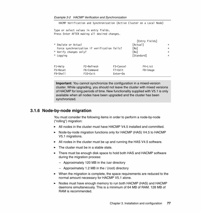
Example 3-2 HACMP Verification and Synchronization
HACMP Verification and Synchronization (Active Cluster on a Local Node)
Type or select values in entry fields.Press Enter AFTER making all desired changes.
[Entry Fields]* Emulate or Actual [Actual] + Force synchronization if verification fails? [No] +* Verify changes only? [No] +* Logging [Standard] +
F1=Help F2=Refresh F3=Cancel F4=ListF5=Reset F6=Command F7=Edit F8=ImageF9=Shell F10=Exit Enter=Do
3.1.6 Node-by-node migrationYou must consider the following items in order to perform a node-by-node (“rolling”) migration:
� All nodes in the cluster must have HACMP V4.5 installed and committed.
� Node-by-node migration functions only for HACMP (HAS) V4.5 to HACMP V5.1 migrations.
� All nodes in the cluster must be up and running the HAS V4.5 software.
� The cluster must be in a stable state.
� There must be enough disk space to hold both HAS and HACMP software during the migration process:
– Approximately 120 MB in the /usr directory
– Approximately 1.2 MB in the / (root) directory
� When the migration is complete, the space requirements are reduced to the normal amount necessary for HACMP V5.1 alone.
� Nodes must have enough memory to run both HACMP (HAS) and HACMP daemons simultaneously. This is a minimum of 64 MB of RAM. 128 MB of RAM is recommended.
Important: You cannot synchronize the configuration in a mixed-version cluster. While upgrading, you should not leave the cluster with mixed versions of HACMP for long periods of time. New functionality supplied with V5.1 is only available when all nodes have been upgraded and the cluster has been synchronized.
Chapter 3. Installation and configuration 77

� Check that you do not have network types unsupported in HACMP. You cannot make configuration changes once migration is started.You must remove or change unsupported types beforehand. See Chapter 3, “Planning Cluster Network Connectivity“, of the HACMP for AIX 5L V5.1 Planning and Installation Guide, SC23-4861-02 for details.
� If any nodes in the cluster are currently set to start cluster services automatically on reboot, change this setting before beginning the migration process. The following procedures describe how to turn off automatic startup for a cluster.
– Use C-SPOC to disable automatic starting of cluster services on system restart.
– Use the SMIT fastpath smitty clstop, and select the options shown in Example 3-3.
Example 3-3 Stop cluster services
Stop Cluster Services
Type or select values in entry fields.Press Enter AFTER making all desired changes.
[Entry Fields]* Stop now, on system restart or both on system restart + Stop Cluster Services on these nodes [p630n01] + BROADCAST cluster shutdown? true +* Shutdown mode graceful +
F1=Help F2=Refresh F3=Cancel F4=ListF5=Reset F6=Command F7=Edit F8=ImageF9=Shell F10=Exit Enter=Do
If you do not use C-SPOC, you must change the setting on each cluster node individually.
Important: As in any migration, once you have started the migration process, do not attempt to make any changes to the cluster topology or resources.
78 IBM Eserver pSeries HACMP V5.x Certification Study Guide Update
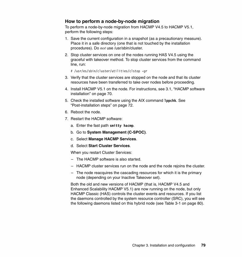
How to perform a node-by-node migrationTo perform a node-by-node migration from HACMP V4.5 to HACMP V5.1, perform the following steps:
1. Save the current configuration in a snapshot (as a precautionary measure). Place it in a safe directory (one that is not touched by the installation procedures). Do not use /usr/sbin/cluster.
2. Stop cluster services on one of the nodes running HAS V4.5 using the graceful with takeover method. To stop cluster services from the command line, run:
# /usr/es/sbin/cluster/utilities/clstop -gr
3. Verify that the cluster services are stopped on the node and that its cluster resources have been transferred to take over nodes before proceeding.
4. Install HACMP V5.1 on the node. For instructions, see 3.1, “HACMP software installation” on page 70.
5. Check the installed software using the AIX command lppchk. See “Post-installation steps” on page 72.
6. Reboot the node.
7. Restart the HACMP software:
a. Enter the fast path smitty hacmp.
b. Go to System Management (C-SPOC).
c. Select Manage HACMP Services.
d. Select Start Cluster Services.
When you restart Cluster Services:
– The HACMP software is also started.
– HACMP cluster services run on the node and the node rejoins the cluster.
– The node reacquires the cascading resources for which it is the primary node (depending on your Inactive Takeover set).
Both the old and new versions of HACMP (that is, HACMP V4.5 and Enhanced Scalability HACMP V5.1) are now running on the node, but only HACMP Classic (HAS) controls the cluster events and resources. If you list the daemons controlled by the system resource controller (SRC), you will see the following daemons listed on this hybrid node (see Table 3-1 on page 80).
Chapter 3. Installation and configuration 79

Table 3-1 List of daemons used by HACMP
8. Repeat steps 2 through 6 for all the other nodes in the cluster.
During the installation and migration process, when you restart each node, the node is running both products, with the HACMP clstrmgr in control of handling cluster events and the clstrmgrES in passive mode.
After you start the cluster services on the last node, the migration to HACMP proceeds automatically. Full control of the cluster transfers automatically to the HACMP V5.1 daemons.
Messages documenting the migration process are logged to the /tmp/hacmp.out file as well as to the /tmp/cm.log and /tmp/clstrmgr.debug log files.
When the migration is complete, and all cluster nodes are up and running HACMP V5.1, the HACMP (HAS) software is uninstalled.
9. After all nodes have been upgraded and rebooted, and the cluster is stable, synchronize and verify the configuration. For more information, see 3.5.8, “Verify and synchronize HACMP” on page 151.
You should also test the cluster’s proper fall-over and recovery behavior after any migration.
HACMP HACMP/ES RSCT
clstmgr clstmgrES grpsvcs
clockd (optional) clockdES (optional) topsvcs
clsmuxpd clsmuxpES emsvcs
clinfo (optional) clinfoES (optional) grpglsm
clcomdES emaixos
Attention: Starting the cluster services on the last node is the point of no return.
Once you have restarted HACMP (which restarts both versions of HACMP) on the last node, and the migration has commenced, you cannot reverse the migration.
If you want to return to the HACMP configuration after this point, you will have to reinstall the HACMP software and apply the saved snapshot. Up to this point, you can back out of the installation of HACMP and return to your running HACMP cluster. If you need to do this, see “Backout procedure” on page 82.
80 IBM Eserver pSeries HACMP V5.x Certification Study Guide Update

config_too_long messageWhen the migration process has completed and the HACMP filesets are being deinstalled, you may see a config_too_long message.
This message appears when the cluster manager detects that an event has been processing for more than the specified time. The config_too_long messages continue to be appended to the hacmp.out log until the event completes. If you observe these messages, you should periodically check that the event is indeed still running and has not failed.
You can avoid these messages by increasing the time to wait before HACMP calls the config_too_long event (use SMIT). To change the interval allocated for an event to process, perform the following steps:
1. Enter the fast path smitty hacmp.
2. Go to Extended Configuration.
3. Select Extended Event Configuration.
4. Select Change/Show Time Until Warning.
You must do this on every node. It takes effect after restarting cluster services.
How the node-by-node migration process worksWhen you have installed HACMP on all cluster nodes (all nodes are now in a hybrid state), starting Cluster Services on the last cluster node automatically triggers the transfer of control to HACMP V5.1 as follows:
1. Installing HACMP V5.1 installs a recovery file called firstboot in a holding directory on the cluster node, and creates a migration file (.mig) to be used as a flag during the migration process.
2. The HACMP recovery driver sends a message to the HACMP Cluster Manager telling it to run the waiting and waiting_complete events.
– HACMP uses the RSCT Group Services to verify cluster stability and membership.
Note: The process of node-by-node migration from HAS 4.5 to HACMP V5.1, you will see the following warnings:
sysck: 3001-036 WARNING: File /etc/cluster/lunreset.lst is also owned by fileset cluster.base.server.events.sysck: 3001-036 WARNING: File /etc/cluster/disktype.lst is also owned by fileset cluster.base.server.events.
You may safely ignore these warnings and proceed with the installation.
Chapter 3. Installation and configuration 81
– The firstboot file on each cluster node is moved to an active directory (/etc).
– The migration flag (.mig file) created during installation is transferred from the HACMP V5.1 directory to the HACMP V4.5 directory on all nodes.
When the firstboot file is moved to the active directory and the.mig file transfer is complete on all nodes, transfer of control to HACMP continues with the HACMP migrate event.
3. The HACMP recovery driver issues the migrate event.
– HACMP V5.1 stops the HACMP V4.5 daemons using the forced option.
– The HACMP V5.1 clinfoES and clsmuxpdES daemons are all activated, reusing the ports previously used by the HACMP V4.5 versions of those daemons.
4. HACMP V5.1 recovery driver runs the migrate_complete event.
– HACMP V4.5 is deinstalled. Configuration files common to both products are left untouched.
– Base directories are relinked.
– The /etc/firstboot files are removed.
– The migration flag (.mig file) in the HACMP /usr/sbin/cluster directory is removed.
5. Migration is now complete.
Cluster snapshots saved during migrationPre-existing HACMP snapshots are saved in the /usr/es/sbin/cluster/snapshots directory.
Handling node failure during the migration processIf a node fails during the migration process after its firstboot file moved to an active directory, it completes the migration process during node reboot. However, the failed node may have an HACMP ODM that is not in synch when it reintegrates into the cluster. In this case, synchronize the topology and resources of the cluster before reintegrating the failed node into the cluster. To synchronize the cluster (see 3.5.8, “Verify and synchronize HACMP” on page 151).
Backout procedureIf for some reason you decide not to complete the migration process, you can uninstall the HACMP V5.1 software on the nodes where you have installed it at any point in the process before starting HACMP on the last node.
82 IBM Eserver pSeries HACMP V5.x Certification Study Guide Update
To deinstall the HACMP software:
1. On each node, one by one, stop cluster services:
To stop cluster services, see Example 3-3 on page 78.
Check that the cluster services are stopped on the node and that its cluster resources have been transferred to takeover nodes before proceeding.
2. When you are sure the resources on the node have been properly transferred to a takeover node, remove the HACMP V5.1 software. See “How to remove the HACMP (HAS) software” on page 75.
3. Start HACMP on this node. When you are certain the resources have transferred properly (if necessary) back to this node, repeat these steps on the next node.
4. Continue this process until HACMP has been removed from all nodes in the cluster.
Handling synchronization failures during node-by-node migrationIf you try to make a change to the cluster topology or resources when migration is incomplete, the synchronization process will fail. You will receive the following message:
cldare: Migration from HACMP V4.5 to HACMP V5.1 Detected. cldare cannot be run until migration has completed.
To back out from the change, you must restore the active ODM. Perform the following steps:
1. Enter smitty hacmp.
2. Go to Problem Determination Tools.
3. Select Restore HACMP Configuration Database from Active Configuration.
Note: Deinstall the HACMP software only on the local node. During a migration, do not select the option to deinstall the software from multiple nodes.
Chapter 3. Installation and configuration 83

3.1.7 Upgrade optionsHere we discuss upgrades to HACMP.
Supported upgrades to HACMP V5.1HACMP conversion utilities provide an easy upgrade path from the versions listed here to V5.1:
� HACMP/ES V4.4.1 to HACMP V5.1
� HACMP/ES V4.5 to HACMP V5.1
If you want to convert to HACMP V5.1 from versions earlier than those listed here, you must first upgrade to one of the supported versions. You will then be able to convert to HACMP V5.1. For example, to convert from HACMP/ES 4.2.2 to HACMP V5.1, you must first perform an installation upgrade to HACMP/ES 4.4.1 or higher and then upgrade to HACMP V5.1.
To upgrade to HACMP V5.1, perform the following steps:
1. Upgrade to AIX 5L V5.1 Maintenance Level 5 or higher if needed.
2. Check and verify the AIX installation, if needed.
3. Commit your current HACMP software on all nodes.
4. Stop HACMP/ES on one node (gracefully with takeover) using the clstop command.
5. After the resources have moved successfully from the stopped node to a takeover node, install the new HACMP software.
For instructions on installing the HACMP V5.1 software, see 3.1, “HACMP software installation” on page 70.
Verify the software installation by using the AIX command lppchk, and check the installed directories to see that expected files are present:
lppchk -v or lppchk -c “cluster.*”
Both commands should run clean if the installation is OK.
6. Reboot the first node.
7. Start the HACMP software on the first node using smitty clstart and verify that the first node successfully joins the cluster.
8. Repeat the preceding steps on remaining cluster nodes, one at a time.
9. Check that the tty device is configured as a serial network.
10.Check that all external disks are available on the first node (use lspv to check the PVIDs for each disk). If PVIDs are not displayed for the disks, you may need to remove the disk and reconfigure them.
84 IBM Eserver pSeries HACMP V5.x Certification Study Guide Update

11.After all nodes have been upgraded, synchronize the node configuration and the cluster topology from Node A to all nodes, as described in “Verifying the upgraded cluster definition” on page 85. Do not skip verification during synchronization.
12.Restore the HACMP event ODM object class to save any pre- and post-events you have configured for your cluster.
13.Make additional changes to the cluster if needed.
14.Complete a test phase on the cluster before putting it into production.
Verifying the upgraded cluster definitionTo verify the cluster, see 3.5.8, “Verify and synchronize HACMP” on page 151.
cl_convert and clconvert_snapshotThe HACMP conversion utilities are cl_convert and clconvert_snapshot.
Upgrading HACMP/ES software to the newest version of HACMP involves converting the ODM from a previous release to that of the current release. When you install HACMP, cl_convert is run automatically. However, if installation fails, you must run cl_convert from the command line.
In a failed conversion, run cl_convert using the -F flag. For example, to convert from HACMP/ES V4.5 to HACMP V5.1, use the -F and -v (version) flags as follows (note the “0” added for V4.5):
# /usr/es/sbin/cluster/conversion/cl_convert -F -v 4.5.0
To run a conversion utility requires:
� Root user privileges� The HACMP version from which you are converting
The cl_convert utility logs the conversion progress to the /tmp/clconvert.log file so that you can gauge conversion success. This log file is generated (overwritten) each time cl_convert or clconvert_snapshot is executed.
The clconvert_snapshot utility is not run automatically during installation, and must be run from the command line. Run clconvert_snapshot to upgrade cluster
Important: When upgrading, never synchronize the cluster definition from an upgraded node, when a node that has not been upgraded remains in a mixed-version cluster. The cl_convert utility assigns node IDs that are consistent across all nodes in the cluster. These new IDs may conflict with the already existing ones.
Chapter 3. Installation and configuration 85
snapshots when migrating from HACMP (HAS) to HACMP, as described in “cl_convert and clconvert_snapshot” on page 85.
Upgrading the concurrent resource managerTo install the concurrent access feature on cluster nodes, install the Concurrent Resource Manager (CRM) using the procedure outlined in 3.1, “HACMP software installation” on page 70.
AIX 5L V5.1 supports enhanced concurrent mode (ECM). If you are installing HACMP with the Concurrent Resource Manager feature, see Chapter 2, “Initial Cluster Planning”, in the HACMP for AIX 5L V5.1 Planning and Installation Guide, SC23-4861-02.
See Chapter 5, “Planning Shared LVM Components“, in the HACMP for AIX 5L V5.1 Planning and Installation Guide, SC23-4861-02, for information about enhanced concurrent mode and on supported IBM shared disk devices. In addition, if you want to use disks from other manufacturers, see Appendix D, “OEM Disk Accommodation”, in the HACMP for AIX 5L V5.1 Planning and Installation Guide, SC23-4861-02.
Problems during the installationIf you experience problems during the installation, the installation program automatically performs a cleanup process. If, for some reason, the cleanup is not performed after an unsuccessful installation, perform the following steps:
1. Enter smitty install.
2. Select Software Maintenance and Utilities.
3. Select Clean Up After a Interrupted Installation.
4. Review the SMIT output (or examine the /smit.log file) for the interruption’s cause.
5. Fix any problems by using AIX problem determination techniques and repeat the installation process.
3.2 Network configurationCluster nodes communicate with each other over communication networks. If one of the physical network interface cards (NIC) on a node on a network fails, HACMP preserves the communication to the node by transferring the traffic to another physical network interface card on the same node. If a “connection” to the node fails, HACMP transfers resources to another available node.
86 IBM Eserver pSeries HACMP V5.x Certification Study Guide Update

In addition, HACMP (via RSCT topology services) uses heartbeat messages between the nodes (over the cluster networks) to periodically check availability of the cluster nodes and communication interfaces. If HACMP detects no heartbeat from a node, the node is considered failed, and its resources are automatically transferred to another node.
Configuring multiple communication paths between the cluster nodes is highly recommended. Having multiple networks prevents cluster partitioning (“split brain”). In a partitioned cluster, the danger is that the nodes in each partition could simultaneously, without coordination, access the same data, which results in data corruption.
3.2.1 Types of networksHere we discuss the types of networks.
Physical and logical networksA physical network connects two or more physical network interfaces. There are many types of physical networks, and HACMP broadly categorizes them as IP-based and non-IP networks:
� TCP/IP-based, such as Ethernet, or Token Ring� Device-based, such as RS-232, or target mode SSA (tmssa)
In HACMP, all network interfaces that can communicate with each other directly are grouped in a logical network. HACMP assigns a name for each HACMP logical network (for example, net_ether_01). A logical network in HACMP may contain one or more IP subnets. RSCT manages the heartbeat packets in each logical subnet.
Global networkA global network is a combination of multiple HACMP networks. The HACMP networks may be composed of any combination of physically different networks, and/or different logical networks (subnets), as long as they share the same “collision domain”, for example, Ethernet. HACMP treats the combined global network as a single network. RSCT handles the routing between the networks defined in a global network.
3.2.2 TCP/IP networksThe IP based networks supported by HACMP are:
� ether (Ethernet)� atm (Asynchronous Transfer Mode - ATM)� fddi (Fiber Distributed Data Interface - FDDI)
Chapter 3. Installation and configuration 87
� hps (SP Switch)� token (Token Ring)
These types of IP based networks are monitored by HACMP via RSCT topology services.
Heartbeat over IP aliasesIn HACMP V5.1, you can configure heartbeat over IP aliases. In prior releases of HACMP, heartbeats were exchanged over the service and non-service IP addresses/labels (base or boot IP addresses/labels).
With this configuration, the communication interfaces’ IP boot addresses can reside on the same subnet or different ones. RSCT sets up separate heartbeat rings for each communication interface group, using a automatically assigned IP aliases, grouped in different subnets. You can use non-routable subnets for the heartbeat rings, preserving your other subnets for routable (client) traffic.
For more information about configuration of heartbeat over IP based network, see 3.4.6, “Defining communication interfaces” on page 121.
Persistent IP addresses/labelsA persistent node IP label is an IP alias that can be assigned to a network for a specified node. A persistent node IP label is a label that:
� Always stays on the same node (is node-bound)
� Co-exists with other IP labels present on the same interface
� Does not require the installation of an additional physical interface on that node
� Is not part of any resource group
Assigning a persistent node IP label for a network on a node allows you to have a node-bound address on a cluster network that you can use for administrative purposes to access a specific node in the cluster. For more information, see 3.4.9, “Defining persistent IP labels” on page 126.
Non-IP networksNon-IP networks in HACMP are used as an independent path for exchanging messages between cluster nodes. In case of IP subsystem failure, HACMP can still differentiate between a network failure and a node failure when an independent path is available and functional. Below is a short description of the four currently available non-IP network types and their characteristics. Even though it is possible to configure an HACMP cluster without non-IP networks, it is strongly recommended that you use at least one non-IP connection between the cluster nodes.
88 IBM Eserver pSeries HACMP V5.x Certification Study Guide Update
Currently HACMP supports the following types of networks for non-TCP/IP heartbeat exchange between cluster nodes:
� Serial (RS232)� Disk heartbeat network (diskhb)� Target-mode SSA (tmssa)� Target-mode SCSI (tmscsi)
Serial (RS232)A serial (RS232) network needs at least one available serial port per cluster node. In case of a cluster consisting of more than two nodes, a ring of nodes is established through serial connections, which requires two serial ports per node. In case the number of native serial ports does not match your HACMP cluster configuration needs, you can extend it by adding an eight-port asynchronous adapter. For more information, see 3.4.7, “Defining communication devices” on page 123.
Disk heartbeat networkIn certain situations RS232, tmssa, and tmscsi connections are considered too costly or complex to set up. Heartbeating via disk (diskhb) provides users with:
� A point-to-point network type that is very easy to configure.
� Additional protection against cluster partitioning.
� A point-to-point network type that can use any disk-type to form a data path.
� A setup that does not require additional hardware; it can use a disk that is also used for data and included in a resource group.
In order to support SSA concurrent VGs, there is a small space reserved on every disk for use in clvmd communication. Enhanced concurrent VGs do not use the reserved space for communication; instead, they use the RSCT group services.
Disk heart beating uses a reserved disk sector (that has been reserved for SSA concurrent mode VGs) as a zone where nodes can exchange keep alive messages.
Any disk that is part of an enhanced concurrent VG can be used for a diskhb network, including those used for data storage. Moreover, the VG that contains the disk used for a diskhb network does not have to be varied on.
Any disk type may be configured as part of an enhanced concurrent VG, making this network type extremely flexible. For more information about configuring a disk heartbeat network, see Chapter 3, “Planning Cluster Network Connectivity”, in the HACMP for AIX 5L V5.1 Planning and Installation Guide, SC23-4861-02.
Chapter 3. Installation and configuration 89
Target mode SSAIf you are using shared SSA devices, target mode SSA can be used for non-IP communication in HACMP. This relies on the built in capabilities of the SSA adapters (using the SCSI communication protocol). The SSA devices in a SSA loop (disks and adapters) use the communication between “initiator” and “target”; SSA disks are “targets”, but the SSA adapter has both capabilities (“initiator” and “target”); thus, a tmssa connection uses these capabilities for establishing a serial-like link between HACMP nodes. This is a point-to point communication network, which can communicate only between two nodes.
To configure a tmssa network between the cluster node, the SSA adapter (one or more) in that node must be part of a SSA loop containing shared disks. In this case, each node must be assigned with a unique node number for the SSA router device (ssar).
To change the SSA node number of the system, perform the following steps:
1. Run the smitty ssa fast path.
2. Select Change/Show SSA Node Number of this System.
3. Change the node number to a unique number in your cluster environment.
For more information about configuring a tmssa network in a cluster, see 3.4.7, “Defining communication devices” on page 123.
Target mode SCSIAnother possibility for a non-IP network is a target mode SCSI connection. Whenever you use a shared SCSI device, you can also use the SCSI bus for exchanging heartbeats. Target mode SCSI (tmscsi) is only supported with SCSI-2 Differential or SCSI-2 Differential Fast/Wide devices. SCSI-1 Single-Ended and SCSI-2 Single-Ended do not support serial networks in an HACMP cluster.
We do not recommend that you use this type of network in any future configurations (since the disk heartbeat network works with any type of supported shared SCSI disk).
Attention: In a cluster that uses concurrent disk access, it is mandatory that the SSA router number matches (is the same as) the HACMP node number; otherwise, you cannot varyon the shared volume groups in concurrent mode.
90 IBM Eserver pSeries HACMP V5.x Certification Study Guide Update
3.3 Storage configurationStorage configuration is one of the most important tasks you have to perform before starting the HACMP cluster configuration. Storage configuration can be considered a part of HACMP configuration.
Depending on the application needs, and on the type of storage, you have to decide that how many nodes in a cluster will have shared storage access, and which resource groups will use which disks.
Most of the IBM storage subsystems are supported with HACMP. To find more information about storage server support, see the HACMP for AIX 5L V5.1 Planning and Installation Guide, SC23-4861-02.
The most commonly used shared storage subsystems are:
� Fiber Attach Storage Server (FAStT)� Enterprise Storage Servers (ESS/Shark)� Serial Architecture Storage (SSA)
Storage protection (data or otherwise) is independent of HACMP; for high availability of storage, you must use storage that has proper redundancy and fault tolerance levels. HACMP does not have any control on storage availability. For data protection, you can use either RAID technology (at storage or adapter level) or AIX LVM mirroring.
Redundant Array of Independent Disks (RAID)Disk arrays are groups of disk drives that work together to achieve data transfer rates higher than those provided by single (independent) drives. Arrays can also provide data redundancy so that no data is lost if one drive (physical disk) in the array fails. Depending on the RAID level, data is either mirrored, striped, or both. For the characteristics of some widely used RAID levels, see Table 3-2 on page 94.
RAID 0RAID 0 is also known as data striping. Conventionally, a file is written out sequentially to a single disk. With striping, the information is split into chunks (fixed amounts of data usually called blocks) and the chunks are written to (or read from) a series of disks in parallel. There are two performance advantages to this:
� Data transfer rates are higher for sequential operations due to the overlapping of multiple I/O streams.
� Random access throughput is higher because access pattern skew is eliminated due to the distribution of the data. This means that with data distributed evenly across a number of disks, random accesses will most likely
Chapter 3. Installation and configuration 91

find the required information spread across multiple disks and thus benefit from the increased throughput of more than one drive.
RAID 0 is only designed to increase performance. There is no redundancy, so any disk failures will require reloading from backups.
RAID 1RAID 1 is also known as disk mirroring. In this implementation, identical copies of each chunk of data are kept on separate disks, or more commonly, each disk has a “twin” that contains an exact replica (or mirror image) of the information. If any disk in the array fails, then the mirror disk maintains data availability. Read performance can be enhanced because the disk that has the actuator (disk head) closest to the required data is always used, thereby minimizing seek times. The response time for writes can be somewhat slower than for a single disk, depending on the write policy; the writes can either be executed in parallel (for faster response) or sequential (for safety).
RAID Level 1 has data redundancy, but data should be regularly saved (backups). This is the only way to recover data in the event that a file or directory is accidentally corrupted or deleted.
RAID 2 and RAID 3RAID 2 and RAID 3 are parallel process array mechanisms, where all drives in the array operate in unison. Similar to data striping, information to be written to disk is split into chunks (a fixed amount of data), and each chunk is written out to the same physical position on separate disks (in parallel). When a read occurs, simultaneous requests for the data can be sent to each disk. This architecture requires parity information to be written for each stripe of data; the difference between RAID 2 and RAID 3 is that RAID 2 can utilize multiple disk drives for parity, while RAID 3 can use only one. If a drive should fail, the system can reconstruct the missing data from the parity and remaining drives. Performance is very good for large amounts of data, but poor for small requests, since every drive is always involved, and there can be no overlapped or independent operation.
RAID 4RAID 4 addresses some of the disadvantages of RAID 3 by using larger chunks of data and striping the data across all of the drives except the one reserved for parity. Using disk striping means that I/O requests need only reference the drive that the required data is actually on. This means that simultaneous, as well as independent reads, are possible. Write requests, however, require a read/modify/update cycle that creates a bottleneck at the single parity drive. Each stripe must be read, the new data inserted, and the new parity then calculated before writing the stripe back to the disk. The parity disk is then updated with the new parity, but cannot be used for other writes until this has
92 IBM Eserver pSeries HACMP V5.x Certification Study Guide Update
completed. This bottleneck means that RAID 4 is not used as often as RAID 5, which implements the same process but without the bottleneck.
RAID 5RAID 5 is very similar to RAID 4. The difference is that the parity information is also distributed across the same disks used for the data, thereby eliminating the bottleneck. Parity data is never stored on the same drive as the chunks that it protects. This means that concurrent read and write operations can now be performed, and there are performance increases due to the availability of an extra disk (the disk previously used for parity). There are other possible enhancements to further increase data transfer rates, such as caching simultaneous reads from the disks and transferring that information while reading the next blocks. This can generate data transfer rates that approach the adapter speed.
As with RAID 3, in the event of disk failure, the information can be rebuilt from the remaining drives. A RAID 5 array also uses parity information, though it is still important to make regular backups of the data in the array. RAID 5 arrays stripe data across all of the drives in the array, one segment at a time (a segment can contain multiple blocks). In an array with n drives, a stripe consists of data segments written to “n-1” of the drives and a parity segment written to the “n-th” drive. This mechanism also means that not all of the disk space is available for data. For example, in an array with five 72 GB disks, although the total storage is 360 GB, only 288 GB are available for data.
RAID 0+1 (RAID 10)RAID 0+1, also known as IBM RAID-1 Enhanced, or RAID 10, is a combination of RAID 0 (data striping) and RAID 1 (data mirroring). RAID 10 provides the performance advantages of RAID 0 while maintaining the data availability of RAID 1. In a RAID 10 configuration, both the data and its mirror are striped across all the disks in the array. The first stripe is the data stripe, and the second stripe is the mirror, with the mirror being placed on the different physical drive than the data. RAID 10 implementations provide excellent write performance, as they do not have to calculate or write parity data. RAID 10 can be implemented via software (AIX LVM), hardware (storage subsystem level), or in a combination of the hardware and software. The appropriate solution for an implementation depends on the overall requirements. RAID 10 has the same cost characteristics as RAID 1.
The most common RAID levels used in today’s IT implementations are listed in Table 3-2 on page 94.
Chapter 3. Installation and configuration 93

Table 3-2 Characteristics of RAID levels widely used
Fiber Attach Storage Server (FAStT)There are different models of FAStT storage available and supported in HACMP. Covering all models of FAStT is not within the scope of this book. To understand how to configure the FAStT storage, we present an example of the FAStT900 Storage Server.
FAStT900 Storage ServerThe FAStT900 Storage Server supports direct attachment of up to four hosts that contain two host adapters each, and is designed to provide maximum host-side and drive-side redundancy. By using external Fibre Channel switches in conjuction with the FAStT900 Storage Server, you can attach up to 64 hosts (each with two host bus adapters) to a FAStT900 Storage Server.
Before configuring the FAStT storage, you must make sure all hardware and cabling connection is done, as per the required configuration. For more information about FAStT cabling, see IBM TotalStorage FAStT900 Fibre Channel Storage Server Installation Guide, GC26-7530.
FAStT Storage Manager softwareThe only way to configure FAStT Storage is to use the FAStT Storage Manager software. The FAStT Storage Manager software is available on most popular operating systems, such as AIX, Linux, and Windows® XP/2000. With FAStT Storage Manager, you can configure supported RAID levels, logical drives, and partitions. Supported RAID levels are RAID 0, RAID 1, RAID 5, and RAID 0+1.
There is no option to configure RAID 10 in FAStT Storage Manager. Selecting RAID 1 with multiple disks, FAStT Manager takes care of striping and mirroring of the data.
RAID level Available disk capacity
Performance in read/write operations
Cost Data Protection
RAID 0 100% High both read/write
Low No
RAID 1 50% Medium/High read, Medium write
High Yes
RAID 5 80% High read Medium write
Medium Yes
RAID 10 50% High both read/write
High Yes
94 IBM Eserver pSeries HACMP V5.x Certification Study Guide Update

It allows a user to format the logical drives as required by the host operating systems. There are different versions of Storage Manager. Storage Manager V8.4 is the supported version of Storage Manager by FAStT900, with some newer features than the previous versions.
Some of the new features supported by FAStT900 with Storage Manager V8.4 are:
� FlashCopy®
A FlashCopy logical drive is a logical point-in-time image of another logical drive, called a base logical drive, that is in the storage subsystem. A FlashCopy is the logical equivalent of a complete physical copy, but you create it much more quickly and it requires less disk space (20% of the original logical drive).
� Remote mirror option
The remote mirror option is used for online, real-time replication of data between storage subsystems over a remote distance.
� Volumecopy
The volumecopy option is a firmware-based mechanism for replicating logical drives data within a storage array. Users submit volumecopy requests by specifying two compatible drives. One drive is designated as the source and the other as a target. The volumecopy request is persistent so that any relevant result of the copy process can be communicated to the user.
� Storage partitioning
Storage partitioning allows the user to present all storage volumes to a SAN through several different partitions by mapping storage volumes to a LUN number, each partition presenting LUNs 0-255. This volume or LUNs mapping applies only to the host port or ports that have been configured to access that LUN. This feature also allows the support of multiple hosts using different operating systems and their own unique disk storage subsystems settings to be connected to the same FAStT storage server at the same time.
For more information about installation and configuration of Storage Manager V8.4, refer the IBM TotalStorage FAStT Storage Manager 8.4 Installation and Support Guide for Intel-based Operating Environments, GC26-7589.
Enterprise Storage Server (ESS/Shark)The IBM Enterprise Storage Server (ESS) is a second-generation Seascape® disk storage system that provides industry-leading availability, performance, manageability, and scalability. RAID levels in ESS are predefined in certain configurations and have limited modification capabilities. Available RAID levels are RAID 1, RAID 5, and RAID 0+1.
Chapter 3. Installation and configuration 95

The IBM Enterprise Storage Server (ESS) does more than simply enable shared storage across enterprise platforms; it can improve the performance, availability, scalability, and manageability of enterprise-wide storage resources through a variety of powerful features. Some of the features are similar in name to those in available FAStT Storage, but the technical concepts differ to a great extent. Some of those features are:
� FlashCopy
FlashCopy provides fast data duplication capability. This option helps eliminate the need to stop applications for extended periods of time in order to perform backups and restores.
� Peer-to-peer remote copy
This feature maintains a synchronous copy (always up-to-date with the primary copy) of data in a remote location. This backup copy of data can be used to quickly recover from a failure in the primary system without losing any transactions; this is an optional capability that can literally keep your e-business applications running.
� Extended remote copy (XRC)
This feature provides a copy of data at a remote location (which can be connected using telecommunications lines at unlimited distances) to be used in case the primary storage system fails. The ESS enhances XRC with full support for unplanned outages. In the event of a telecommunications link failure, this optional function enables the secondary remote copy to be resynchronized quickly without requiring duplication of all data from the primary location for full disaster recovery protection.
� Custom volumes
Custom volumes enable volumes of various sizes to be defined for high-end servers, enabling administrators to configure systems for optimal performance.
� Storage partitioning
Storage partitioning uses storage devices more efficiently by providing each server access to its own pool of storage capacity. Storage pools can be shared among multiple servers.
For more information about the configuration of the Enterprise Storage Server, refer to the IBM TotalStorage Enterprise Storage Server Service Guide 2105 Model 750/800 and Expansion Enclosure, Volume 1, SY27-7635.
96 IBM Eserver pSeries HACMP V5.x Certification Study Guide Update

Serial Storage Architecture (SSA)Serial storage architecture is an industry-standard interface that provides high-performance fault-tolerant attachment of I/O storage devices. In SSA subsystems, transmissions to several destinations are multiplexed; the effective bandwidth is further increased by spatial reuse of the individual links. Commands are forwarded automatically from device to device along a loop until the target device is reached. Multiple commands can be travelling around the loop simultaneously.
SSA supports RAID 0, RAID 1, RAID 5, and RAID 0+1. To use any of the RAID setups, it is necessary to follow the looping instruction of SSA enclosures. Specific looping across the disk is required to create RAID. For more information about IBM SSA RAID Configuration, refer to IBM Advanced SerialRAID Adapters Installation Guide, SA33-3287.
3.3.1 Shared LVMFor a HACMP cluster, the key element is the data used by the highly available applications. This data is stored on AIX Logical Volume Manager (LVM) entities. HACMP clusters use the capabilities of the LVM to make this data accessible to multiple nodes. AIX Logical Volume Manager provides shared data access from multiple nodes. Some of the components of shared logical volume manager are:
� A shared volume group is a volume group that resides entirely on the external disks shared by cluster nodes.
� A shared physical volume is a disk that resides in a shared volume group.
� A shared logical volume is a logical volume that resides entirely in a shared volume group.
� A shared file system is a file system that resides entirely in a shared logical volume.
If you are an system administrator of an HACMP cluster, you may be called upon to perform any of the following LVM-related tasks:
� Create a new shared volume group.
� Extend, reduce, change, or remove an existing volume group.
� Create a new shared logical volume.
� Extend, reduce, change, or remove an existing logical volume.
� Create a new shared file system.
� Extend, change, or remove an existing file system.
� Add and remove physical volumes.
Chapter 3. Installation and configuration 97

When performing any of these maintenance tasks on shared LVM components, make sure that ownership and permissions are reset when a volume group is exported and then re-imported.
After exporting and importing, a volume group is owned by root and accessible by the system group.
Shared logical volume access can be made available in any of the following data accessing modes:
� Non-concurrent access mode� Concurrent access mode� Enhanced concurrent access mode
3.3.2 Non-concurrrent access modeHACMP in a non-concurrent access environment typically uses journaled file systems to manage data, though some database applications may bypass the journaled file system and access the logical volume directly.
Both mirrored and non-mirrored configuration is supported by non-concurrent access of LVM. For more information about creating mirrored and non-mirrored logical volumes, refer to the HACMP for AIX 5L V5.1 Planning and Installation Guide, SC23-4861-02.
To create a non-concurrent shared volume group on a node, perform the following steps:
1. Use the fast path smitty mkvg.
2. Use the default field values unless your site has other specific requirements.
– VOLUME GROUP name
The name of the shared volume group should be unique within the cluster.
– Activate volume group AUTOMATICALLY at system restart?
Set to No so that the volume group can be activated as appropriate by the cluster event scripts.
– ACTIVATE volume group after it is created?
Set to Yes.
Note: Applications, such as some database servers, that use raw logical volumes may be affected by this change if they change the ownership of the raw logical volume device. You must restore the ownership and permissions back to what is needed after this sequence.
98 IBM Eserver pSeries HACMP V5.x Certification Study Guide Update

– Volume Group MAJOR NUMBER
Make sure to use the same major number on all nodes. Use the lvlstmajor command on each node to determine a free major number common to all nodes.
To create a non-concurrent shared filesystem on a node, perform the following steps:
1. Use the fast path smitty crjfs.
2. Rename both the logical volume and the log logical volume for the file system and volume group.
AIX assigns a logical volume name to each logical volume it creates. Examples of logical volume names are /dev/lv00 and /dev/lv01. Within an HACMP cluster, the name of any shared logical volume must be unique. Also, the journaled file system log (jfslog) is a logical volume that requires a unique name in the cluster.
3. Review the settings for the following fields:
– Mount automatically at system restart?
Make sure this field is set to No.
– Start Disk Accounting
Set this field to No unless you want disk accounting.
4. Test the newly created file system by mounting and unmounting it.
Importing a volume group to a fall-over nodeBefore you import the volume group, make sure the volume group is varied off from the primary node. You can then run the discovery process of HACMP, which will collect the information about all volume groups available across all nodes.
Importing the volume group onto the fall-over node synchronizes the ODM definition of the volume group on each node on which it is imported.
When adding a volume group to the resource group, you may choose to manually import a volume group onto the fall-over node or you may choose to automatically import it onto all the fall-over node in the resource group.
For more information about importing volume groups, see the HACMP for AIX 5L V5.1 Planning and Installation Guide, SC23-4861-02.
Chapter 3. Installation and configuration 99

3.3.3 Concurrent access modeUsing concurrent access with HACMP requires installing an additional fileset. For additional information, see Chapter 2, “Planning and design” on page 17.
Concurrent access mode is not supported for file systems; instead, you must use raw logical volumes or physical disks.
Creating a concurrent access volume group1. The physical volumes (hdisk*) should be installed, configured, and available.
You can verify the disks’ status using the following command:
# lsdev -Cc disk
2. To use a concurrent access volume group, you must create it as a concurrent capable volume group. A concurrent capable volume group can be activated (varied on) in either non-concurrent mode or concurrent access mode.
To create a concurrent access volume group, perform the following steps:
a. Enter smit cl_convg.
b. Select Create a Concurrent Volume Group.
c. Enter the field values as desired.
d. Press Enter.
Import the concurrent capable volume groupImporting the concurrent capable volume group is done by running the following command:
# importvg -C -y vg_name physical_volume_name
Specify the name of any disk in the volume group as an argument to the importvg command. By default, AIX automatically varies on non-concurrent capable volume groups when they are imported. AIX does not automatically varyon concurrent capable volume groups when they are imported.
Note: After importing a volume group on the fall-over node, it is necessary to change the volume group startup status. Run following command to change the volume group status, as required by HACMP:
# chvg -an -Qn <vgname>
This will disable automatic varyon when the system restarts and also disable the quorum of the volume group.
100 IBM Eserver pSeries HACMP V5.x Certification Study Guide Update
Varyon the concurrent capable VGs in non-concurrent modeIt is necessary to varyon the concurrent capable volume group in a non-concurrent mode to create logical volume. Use the varyonvg command to activate a volume group in non-concurrent mode:
# varyonvg <vgname>
Create logical volumes on the concurrent capable volume groupYou can create logical volumes on the volume group, specifying the logical volume mirrors to provide data redundancy.
To create logical volumes on a concurrent capable volume group on a source node, perform the following steps:
1. Use the SMIT fast path smit cl_conlv.
2. Specify the size of the logical volume as the number of logical partitions.
3. Specify the desired values to the other available option.
4. Press Enter.
Varyoff a volume group After creating the logical volume, varyoff the volume group using the varyoffvg command so that it can be varied on by the HACMP scripts. Enter:
# varyoffvg <vgname>
Define a concurrent volume group in an HACMP resource groupTo start the concurrent volume group simultaneously on all the nodes, specify the volume group name in the startup scripts of HACMP.
On cluster startup, you may find the concurrent volume group is activated on all the configured nodes. For more information about configuring HACMP resource groups, refer to 3.5, “Resource group configuration” on page 128.
3.3.4 Enhanced concurrent mode (ECM) VGsWith HACMP V5.1, you now have the ability to create and use enhanced concurrent VGs. These can be used for both concurrent and non-concurrent access. You can also convert existing concurrent (classic) volume groups to enhanced concurrent mode using C-SPOC.
For enhanced concurrent volume groups that are used in a non-concurrent environment, rather than using the SCSI reservation mechanism, HACMP V5.1 uses the fast disk takeover mechanism to ensure fast takeover and data integrity.
Chapter 3. Installation and configuration 101

The ECM volume group is varied on all nodes in the cluster that are part of that resource group. However, the access for modifying data is only granted to the node that has the resource group active (online).
Active and passive varyon in ECMAn enhanced concurrent volume group can be made active on the node, or varied on, in two modes: active or passive.
Active varyonIn the active state, all high level operations are permitted. When an enhanced concurrent volume group is varied on in the active state on a node, it allows the following:
� Operations on file systems, such as file system mounts� Operations on applications� Operations on logical volumes, such as creating logical volumes� Synchronizing volume groups
Passive varyonWhen an enhanced concurrent volume group is varied on in the passive state, the LVM provides the equivalent of fencing for the volume group at the LVM level. The node that has the VG varied on in passive mode is allowed only a limited number of read-only operations on the volume group:
� LVM read-only access to the volume group’s special file
� LVM read-only access to the first 4 KB of all logical volumes that are owned by the volume group
The following operations are not allowed when a volume group is varied on in the passive state:
� Operations on file systems, such mount� Any open or write operation on logical volumes� Synchronizing volume groups
Note: Fast disk takeover in HACMP V5.1 is available only in AIX 5L V5.2.
102 IBM Eserver pSeries HACMP V5.x Certification Study Guide Update

Creating a enhanced concurrent access volume group1. When concurrent volume groups are created on AIX 5L 5.1 and later, they are
automatically created in enhanced concurrent mode.
2. To create a concurrent capable volume group from the AIX command line, use the mkvg command. For example:
# mkvg -n -s 32 -C -y myvg hdisk11 hdisk12
will create an enhanced concurrent VG on hdisk11 and hdisk12. The flags do the following:
-n Do not vary on VG at boot.
-s 32 Gives a partition size of 32 MB.
-C Creates an enhanced concurrent VG.
-y Specifies the VG name.
3.3.5 Fast disk takeoverThis is a new feature of HACMP V5.1, which has the following main purposes:
� Decreases the application downtime, with faster resource group fallover (and movement)
� Concurrent access to a volume group (preserving the data integrity)
� Uses AIX Enhanced Concurrent VGs (ECM)
� Uses RSCT for communications
The enhanced concurrent volume group supports active and passive mode varyon, and can be included in an non-concurrent resource group.
The fast disk takeover is set up automatically by the HACMP software. For all shared volume groups that have been created in enhanced concurrent mode and contain file systems, HACMP will activate the fast disk takeover feature. When HACMP starts, all nodes in a Resource Group that share the same enhanced Volume Group will varyon that Volume Group in passive mode. When the Resource Group is brought online, the node that acquires the resources will varyon the Volume Group in active mode.
The other nodes will maintain the Volume Group variedon in passive mode. In this case, all the changes to the Volume Group will be propagated automatically to all the nodes in that Volume Group. The change from active to passive mode and the reverse are coordinated by HACMP at cluster startup, Resource Group activation and failover, and when a failing node rejoins the cluster.
Chapter 3. Installation and configuration 103
The prerequisites for this functionality are:
� HACMP V5.1� AIX 5L 5.2 or higher� bos.clvm.5.2.0.11 or higher� APAR IY44237
For more information about fast disk takeover, see the HACMP for AIX 5L V5.1 Planning and Installation Guide, SC23-4861-02.
3.4 Configuring cluster topologyThe cluster topology represents the physical components of the cluster and how they are connected via networks (IP and non-IP).
3.4.1 HACMP V5.x Standard and Extended configurationsHACMP V5.1 has introduced the Standard and the Extended SMIT configuration paths.
Standard configuration pathThe Standard path allows users to easily configure the most common options, such as:
� IPAT via Aliasing Networks� Shared Service IP Labels� Volume Groups and File systems� Application Servers
When using the options under the Initialization and Standard Configuration SMIT menu, you can add the basic components of a cluster to the HACMP configuration in a few steps. HACMP configuration is automatically discovered and used for defining a cluster with most common options (see Example 3-4 on page 105 and Example 3-5 on page 105).
104 IBM Eserver pSeries HACMP V5.x Certification Study Guide Update

Example 3-4 HACMP for AIX
HACMP for AIX
Move cursor to desired item and press Enter.
Initialization and Standard Configuration Extended Configuration System Management (C-SPOC) Problem Determination Tools
F1=Help F2=Refresh F3=Cancel F8=ImageF9=Shell F10=Exit Enter=Do
Example 3-5 Initialization and Standard Configuration
Initialization and Standard ConfigurationMove cursor to desired item and press Enter.Add Nodes to an HACMP Cluster Configure Resources to Make Highly Available Configure HACMP Resource Groups Verify and Synchronize HACMP Configuration Display HACMP Configuration
F1=Help F2=Refresh F3=Cancel F8=ImageF9=Shell F10=Exit Enter=Do
Prerequisite tasks for using the standard pathTo use the standard configuration path, HACMP V5.1 must be installed on all the nodes, and connectivity must exist between the node where you are performing the configuration and all other nodes to be included in the cluster.
At least one network interface on each node must be both physically (VLAN and switch) and logically (subnets) configured so that you can successfully communicate from one node to each of the other nodes.
Once you have configured and powered on all disks, communication devices, serial networks, and configured communication paths to other nodes in AIX, HACMP automatically collects information about the physical and logical configuration and displays it in corresponding SMIT picklists, to aid you in the HACMP configuration process.
Chapter 3. Installation and configuration 105

With the connectivity path established, HACMP can discover cluster information and you are able to access all of the nodes needed to perform any necessary AIX administrative tasks. You do not need to open additional windows or physically move to other nodes' consoles and manually log in to each node individually. SMIT fast paths to the relevant HACMP and/or AIX SMIT screens on the remote nodes are available within the HACMP SMIT screens.
Assumptions and defaults for the standard pathThe software makes some assumptions regarding the environment, such as assuming all network interfaces on a physical network belong to the same HACMP network. Intelligent and/or default parameters are supplied or automatically configured. This helps to minimize the number of steps needed to configure the cluster.
Basic assumptions are:
� The host names (as revealed by the hostname command) are used as node names. All network interfaces that can “see” each other’s MAC address are automatically configured in HACMP. Those network interfaces that can ping each other without going through a router are placed on the same logical network. HACMP names each logical network.
� IP aliasing is used as the default mechanism for service IP label/address assignment to a network interface.
� IP Address Takeover via IP Aliases is configured for any logical network capable of taking over a service IP label as an alias.
� You can configure the resource groups with basic predefined management policies (fall-over and fall-back preferences: cascading, rotating or concurrent) or the new custom resource groups.
Adding, changing, or deleting serial (non-IP) networks and devices is done via the Extended path, since you must manually define the desired communication devices (end-points) for each point-to-point network.
For further configuration, or to add more details or customization to the cluster configuration, use the HACMP Extended Configuration SMIT path. For further reference, see “Extended configuration path” on page 111.
Note: To configure the IP Adress Takeover via IP replacement mechanism, you have to use the Extended configuration path to change the HACMP network properties (you turn off IP aliasing).
106 IBM Eserver pSeries HACMP V5.x Certification Study Guide Update

Steps for configuring a cluster using the standard path1. Configure the cluster topology.
Identify the cluster nodes and establish communication paths between them using the Configure Nodes to an HACMP Cluster menu options. Here you name the cluster and select the nodes (listed in /etc/hosts) either by their names or their IP addresses. This gives HACMP the base knowledge it needs to communicate with the nodes that are participating in the cluster.
Once each of the nodes is properly identified and a working communication paths exist, HACMP automatically runs a discovery operation that identifies the basic components within the cluster.
The discovered host names are used as the node names and added to the HACMP node ODM. The networks (and the associated interfaces) that share physical connectivity with two or more nodes in the cluster are automatically added to the HACMP network and HACMP adapter ODMs. Other discovered shared resource information includes PVIDs, and volume groups (see Example 3-6).
Example 3-6 Configuring nodes in a cluster (standard)
Configure Nodes to an HACMP Cluster (standard)
Type or select values in entry fields.Press Enter AFTER making all desired changes.
[Entry Fields]* Cluster Name [cluster5x] New Nodes (via selected communication paths) [] + Currently Configured Node(s) p630n01 p630n02 p630n>
F1=Help F2=Refresh F3=Cancel F4=ListF5=Reset F6=Command F7=Edit F8=Image9=Shell F10=Exit Enter=Do
2. Configure the cluster resources.
Configure the resources to be made highly available. Use the Configure Resources to make Highly Available menu to configure resources that are to be shared among the nodes in the cluster (see Example 3-7 on page 108).
Note: When using the standard HACMP configuration SMIT path, if any information needed for configuration resides on remote nodes, then discovery of cluster information will automatically be performed.
Chapter 3. Installation and configuration 107

You can configure these resources:
– IP address/IP label– Application server– Volume groups (shared and concurrent)– Logical volumes– File systems
Example 3-7 Configure resources to make high available
Configure Resources to Make Highly Available
Move cursor to desired item and press Enter.
Configure Service IP Labels/Addresses Configure Application Servers Configure Volume Groups, Logical Volumes and Filesystems Configure Concurrent Volume Groups and Logical Volumes
F1=Help F2=Refresh F3=Cancel F8=ImageF9=Shell F10=Exit Enter=Do
3. Configure the resource groups.
Use the Configure HACMP Resource Groups menu to create the resource groups you have planned for each set of related or dependent resources.
You can choose to configure cascading, rotating, concurrent, or custom resource groups (note that you cannot specify the fallback timer policies for the custom resource groups in the Standard menu) (see Example 3-8).
Example 3-8 Configure an HACMP resource group (Standard)
Configure HACMP Resource Groups
Move cursor to desired item and press Enter.
Add a Resource Group Change/Show a Resource Group Remove a Resource Group Change/Show Resources for a Resource Group (standard)
F1=Help F2=Refresh F3=Cancel F8=ImageF9=Shell F10=Exit Enter=Do
4. Group the resources to be managed together into the previously defined resource group(s).
108 IBM Eserver pSeries HACMP V5.x Certification Study Guide Update
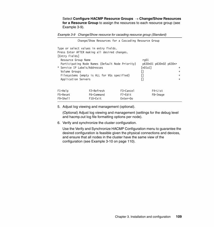
Select Configure HACMP Resource Groups → Change/Show Resources for a Resource Group to assign the resources to each resource group (see Example 3-9).
Example 3-9 Change/Show resource for cacading resource group (Standard)
Change/Show Resources for a Cascading Resource Group
Type or select values in entry fields.Press Enter AFTER making all desired changes.[Entry Fields] Resource Group Name rg01 Participating Node Names (Default Node Priority) p630n01 p630n02 p630n>* Service IP Labels/Addresses [n01a1] + Volume Groups [] + Filesystems (empty is ALL for VGs specified) [] + Application Servers [] +
F1=Help F2=Refresh F3=Cancel F4=ListF5=Reset F6=Command F7=Edit F8=ImageF9=Shell F10=Exit Enter=Do
5. Adjust log viewing and management (optional).
(Optional) Adjust log viewing and management (settings for the debug level and hacmp.out log file formatting options per node).
6. Verify and synchronize the cluster configuration.
Use the Verify and Synchronize HACMP Configuration menu to guarantee the desired configuration is feasible given the physical connections and devices, and ensure that all nodes in the cluster have the same view of the configuration (see Example 3-10 on page 110).
Chapter 3. Installation and configuration 109

Example 3-10 Verification and synchronization of cluster
Command: running stdout: yes stderr: no
Before command completion, additional instructions may appear below.
Verification to be performed on the following: Cluster Topology Cluster Resources
Retreiving data from available cluster nodes. This could take a few minutes...
Verifying Cluster Topology...
7. Display the cluster configuration (optional). See Example 3-11. Review the cluster topology and resources configuration.
Example 3-11 Display HACMP information
Command: OK stdout: yes stderr: noBefore command completion, additional instructions may appear below.Cluster Description of Cluster: cluster5xCluster Security Level: StandardThere are 6 node(s) and 2 network(s) definedNODE p630n01: Network net_ether_01 gp01 10.1.1.1 Network net_ether_02 n06a1 192.168.11.136 n05a1 192.168.11.135 n04a1 192.168.11.134 n02a1 192.168.11.132 n01a1 192.168.11.131F1=Help F2=Refresh F3=Cancel F6=CommandF8=Image F9=Shell F10=Exit /=Findn=Find Next
8. Make further additions or adjustments to the cluster configuration (optional).
You may want to use some options available on the HACMP Extended Configuration path. Such additions or adjustments include (for example):
– Adding non-IP networks for heartbeating
– Adding other resources, such as SNA communication interfaces and links or tape resources
– Configuring resource group run-time policies, including Workload Manager
– Adding custom resource group timers
110 IBM Eserver pSeries HACMP V5.x Certification Study Guide Update
– Configuring cluster security
– Customizing cluster events
– Configuring site policies
Extended configuration pathThe Extended path allows users fine control over the configuration:
� Configuration discovery is optional.
� Node names do not need to match host names.
� IP network topology may be configured according to a specific user's environment.
Using the options under the Extended Configuration menu you can add the basic components of a cluster to the HACMP configuration database (ODM), as well as all additional types of resources.
Steps for configuring the cluster using the extended path1. Run discovery (optional)
Run discovery if you have already configured some or all of the cluster components. Running discovery retrieves current AIX configuration information from all cluster nodes. This information is displayed in picklists to help you make accurate selections of existing components. The discovered components are highlighted as predefined components and made available for selections (see Example 3-12).
Example 3-12 Discovering information from other nodes (Extended)
Command: OK stdout: yes stderr: no
Before command completion, additional instructions may appear below.
[TOP]Discovering IP Network Connectivity
Retreiving data from available cluster nodes. This could take a few minutes...Discovered [24] interfacesIP Network Discovery completed normallyDiscovering Volume Group Configurationclharvest_vg: Initializing....Gathering cluster information, which may take a few minutes...clharvest_vg: Processing...Storing the following information in file/usr/es/sbin/cluster/etc/config/clvg_config
p630n01:
Chapter 3. Installation and configuration 111

Hdisk: hdisk0PVID: 0006856f612dab6eVGname: rootvgVGmajor: active[MORE...1761]
F1=Help F2=Refresh F3=Cancel F6=CommandF8=Image F9=Shell F10=Exit /=Findn=Find Next
2. Configure, change, or customize the cluster topology.
Under the Extended Topology Configuration menu, you can:
Identify the nodes and establish communication paths between them using the Configure Nodes to an HACMP Cluster menu. In this case, you name the cluster and select the nodes (listed in /etc/hosts) either by their names or their IP addresses. This gives HACMP the information needed to communicate with the nodes that are participating in the cluster.
You can also:
– Select the PVIDs and the existing volume groups.
– Configure, change, or show sites (optional).
– Configure, change, or show predefined or discovered IP-based networks, and predefined or discovered serial devices.
– Configure, change, show and update HACMP communication interfaces and devices with AIX settings.
– Configure previously defined, or previously discovered, communication interfaces and devices.
– Configure, change, and show persistent Node IP Labels.
See Example 3-13 on page 113 for more details.
112 IBM Eserver pSeries HACMP V5.x Certification Study Guide Update

Example 3-13 Extended topology configuration
Extended Topology Configuration
Move cursor to desired item and press Enter.
Configure an HACMP Cluster Configure HACMP Nodes Configure HACMP Sites Configure HACMP Networks Configure HACMP Communication Interfaces/Devices Configure HACMP Persistent Node IP Label/Addresses Configure HACMP Global Networks Configure HACMP Network Modules Configure Topology Services and Group Services Show HACMP Topology
F1=Help F2=Refresh F3=Cancel F8=ImageF9=Shell F10=Exit Enter=Do
3. Configure or customize the resources to be made highly available.
Use the Configure Resources to Make Highly Available menu to configure resources that are to be shared among the nodes in the cluster, so that if one component fails, another component will automatically take its place (see Example 3-14 on page 114). You can configure the following resources:
– Service IP address (labels)
– Application servers
– Volume groups
– Concurrent volume groups
– Logical volumes
– File systems
– Application monitoring
– Tape resources
– Communication adapters and links for the operating system
– HACMP communication interfaces and links
– Custom disk methods
Chapter 3. Installation and configuration 113
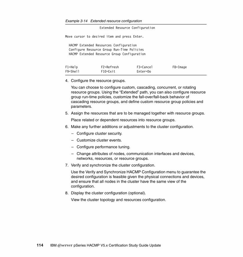
Example 3-14 Extended resource configuration
Extended Resource Configuration
Move cursor to desired item and press Enter.
HACMP Extended Resources Configuration Configure Resource Group Run-Time Policies HACMP Extended Resource Group Configuration
F1=Help F2=Refresh F3=Cancel F8=ImageF9=Shell F10=Exit Enter=Do
4. Configure the resource groups.
You can choose to configure custom, cascading, concurrent, or rotating resource groups. Using the “Extended” path, you can also configure resource group run-time policies, customize the fall-over/fall-back behavior of cascading resource groups, and define custom resource group policies and parameters.
5. Assign the resources that are to be managed together with resource groups.
Place related or dependent resources into resource groups.
6. Make any further additions or adjustments to the cluster configuration.
– Configure cluster security.
– Customize cluster events.
– Configure performance tuning.
– Change attributes of nodes, communication interfaces and devices, networks, resources, or resource groups.
7. Verify and synchronize the cluster configuration.
Use the Verify and Synchronize HACMP Configuration menu to guarantee the desired configuration is feasible given the physical connections and devices, and ensure that all nodes in the cluster have the same view of the configuration.
8. Display the cluster configuration (optional).
View the cluster topology and resources configuration.
114 IBM Eserver pSeries HACMP V5.x Certification Study Guide Update
3.4.2 Define cluster topology
Here we define the cluster topology.
Standard topology configurationComplete the following procedures to define the cluster topology. You only need to perform these steps on one node. When you verify and synchronize the cluster topology, its definition is copied to the all other nodes.
1. Enter smitty hacmp.
2. Select Initialization and Standard Configuration → Configure Nodes to an HACMP Cluster and press Enter.
3. In the Configure Nodes to an HACMP Cluster screen enter the values as follows:
– Cluster name
Enter an ASCII text string that identifies the cluster. The cluster name can include alpha and numeric characters and underscores, but cannot have a leading numeric. Use no more than 31 characters. It can be different from the host name. Do not use reserved names.
– New nodes via selected communication paths
Enter (or add) one resolvable IP Label (this may be the host name), IP address, or Fully Qualified Domain Name for each new node in the cluster, separated by spaces. This path will be taken to initiate communication with the node. Use F4 to see the picklist display of the host names and/or addresses in /etc/hosts that are not already configured in HACMP (see Figure 3-1 on page 116).
Chapter 3. Installation and configuration 115
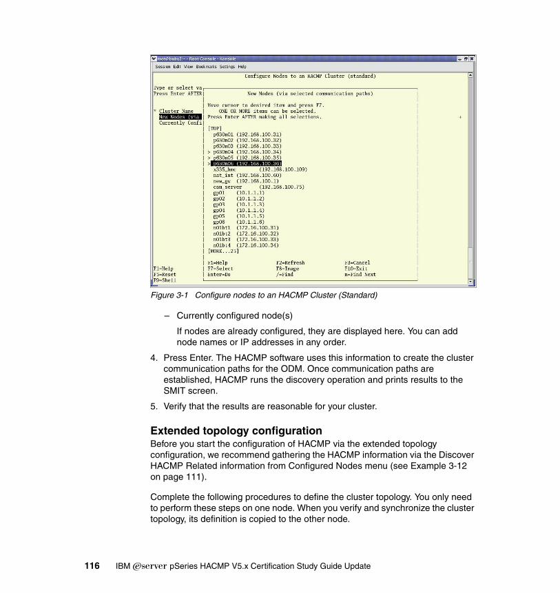
Figure 3-1 Configure nodes to an HACMP Cluster (Standard)
– Currently configured node(s)
If nodes are already configured, they are displayed here. You can add node names or IP addresses in any order.
4. Press Enter. The HACMP software uses this information to create the cluster communication paths for the ODM. Once communication paths are established, HACMP runs the discovery operation and prints results to the SMIT screen.
5. Verify that the results are reasonable for your cluster.
Extended topology configurationBefore you start the configuration of HACMP via the extended topology configuration, we recommend gathering the HACMP information via the Discover HACMP Related information from Configured Nodes menu (see Example 3-12 on page 111).
Complete the following procedures to define the cluster topology. You only need to perform these steps on one node. When you verify and synchronize the cluster topology, its definition is copied to the other node.
116 IBM Eserver pSeries HACMP V5.x Certification Study Guide Update

The Extended topology configuration screens include:
� Configuring an HACMP cluster
� Configuring HACMP nodes
� Configuring HACMP sites
� Configuring HACMP networks
� Configuring communication interfaces
� Configuring communication devices
� Configuring HACMP persistent IP labels
� Configuring HACMP network modules
Configuring an HACMP clusterThe only step necessary to configure the cluster is to assign the cluster name. Perform the following steps:
1. Enter smitty hacmp.
2. Go to Extended Configuration.
3. Select Extended Topology Configuration.
4. Select Configure an HACMP Cluster.
5. Select Add/Change/Show an HACMP Cluster and press Enter.
6. Enter the following values:
– Cluster name
Enter an ASCII text string that identifies the cluster. The cluster name can include alpha and numeric characters and underscores, but cannot have a leading numeric. Use no more than 31 characters.
The node name can be different from the host name. Do not use reserved names. For a list of reserved names, see the HACMP List of Reserved Words, which are found in Chapter 6, “Verifying and Synchronizing a Cluster Configuration“, of the HACMP for AIX 5L V5.1 Administration and Troubleshooting Guide, SC23-4862-00.
7. Press Enter.
8. Press F3 until you return to the Extended Topology SMIT screen.
Chapter 3. Installation and configuration 117

3.4.3 Defining a nodeDefining node using a standard path is not an available option. HACMP automatically takes the host name of the discovered IP network as a node name.
If you want to define nodes manually, you need to use the extended SMIT path of HACMP.
To define the cluster nodes using the extended path, perform the following steps:
1. Enter the fast path smitty hacmp.
2. Go to Extended Configuration.
3. Select Extended Topology Configuration.
4. Select Configure HACMP Nodes.
5. Select Add a Node to the HACMP Cluster and press Enter.
6. Enter field values as follows:
– Node name
Enter (or add) one resolvable IP Label (this may be the host name), IP address, or Fully Qualified Domain Name for each new node in the cluster, up to 31, separated by spaces. This path will be taken to initiate communication with the node. Use F4 to see the picklist display of the contents of /etc/hosts that are not already HACMP-configured IP Labels/Addresses.
– Communication path to node
If nodes are already configured, they are displayed here.
The HACMP software uses this information to create the cluster communication paths for the ODM. Once communication paths are established, HACMP updates the authentication information for the cluster communication daemon.
3.4.4 Defining sitesSite definitions are optional. They are supplied to provide easier integration with the HAGEO product. If you define sites to be used outside of HAGEO, appropriate methods or customization must be provided to handle site operations. If sites are defined, site events run during node_up and node_down events.
To add a site definition to an HACMP cluster, perform the following steps:
1. Enter the fast path smitty hacmp.
2. Go to Extended Configuration.
118 IBM Eserver pSeries HACMP V5.x Certification Study Guide Update
3. Select Extended Topology Configuration.
4. Select Configure HACMP Sites.
5. Select Cluster Configuration.
6. Select Cluster Topology.
7. Select Configure Sites.
8. Select Add Site Definition and press Enter.
9. Enter the filed values as follows:
– Site name
Enter a name for this site using no more than 32 alphanumeric characters and underscores.
– Site nodes
Enter the names of the cluster nodes that belong to the site. Leave a space between names. A node can belong to only one site.
– Dominance
(If HAGEO is installed.) Choose yes or no to indicate whether the current site is dominant or not.
– Backup communications
(If HAGEO is installed.) Select the type of backup communication for your HAGEO cluster (DBFS for telephone line, SGN for a Geo_Secondary network). You can also select None.
• Press Enter to add the site definition to the ODM.• Repeat the steps to add the second site.
3.4.5 Defining network(s)The cluster should have more than one network, to avoid a single point of failure. Often the cluster has both IP and non-IP based networks in order to use different heartbeat paths.
Use the Add a Network to the HACMP Cluster SMIT screen to define HACMP IP and non-IP networks. To speed up the process, we recommend that you run discovery before network configuration. Running discovery may also reveal any “strange” networking configurations at your site.
You can use any or all of these methods for heartbeat paths:
� Serial networks� IP-based networks, including heartbeat using IP aliases� Heartbeat over disk
Chapter 3. Installation and configuration 119

IP-based networksTo configure IP-based networks, perform the following steps:
1. Enter the fast path smitty hacmp.
2. Go to Extended Configuration.
3. Select Extended Topology Configuration.
4. Select Configure HACMP Networks.
5. Select Add a Network to the HACMP Cluster and press Enter.
6. Select the type of network to configure and press Enter.
7. Enter the information as follows:
– Network name
If you do not enter a name, HACMP will give the network a default network name made up of the type of network with a number appended (for example, ether1). If you change the name for this network, use no more than 31 alphanumeric characters and underscores.
– Network type
This field is filled in, depending on the type of network you selected.
– Netmask
The network mask, for example, 255.255.0.0.
– Enable IP takeover via IP aliases
The default is True. If the network does not support IP aliases, then IP Replacement will be used. IP Replacement is the mechanism whereby one IP address is removed from an interface, and another IP address is added to that interface. If you want to use IP Replacement on a network that does support aliases, change the default to False.
– IP address offset for heartbeating over IP aliases
Enter the base address of a private address range for heartbeat addresses, for example, 10.10.10.1. HACMP will use this address to automatically generate IP addresses for heartbeat for each boot interface in the configuration. This address range must be unique and must not conflict with any other subnets on the network.
8. Press Enter to configure this network.
9. Press F3 to return to configure more networks.
Configuring IPAT via IP replacementIf you do not have extra subnets to use in the HACMP cluster, you may need to configure IPAT via IP Replacement. In HACMP V5.1, IPAT via IP Aliases is the
120 IBM Eserver pSeries HACMP V5.x Certification Study Guide Update
default method for binding an IP label to a network interface, and for ensuring the IP label recovery. IPAT via IP aliases saves hardware, but requires multiple subnets.
The steps for configuring IPAT via IP Replacement are:
1. In the Add a Service IP Label/Address SMIT screen, specify that the IP label that you add as a resource to a resource group is Configurable on Multiple Nodes.
2. In the same screen, configure hardware address takeover (HWAT) by specifying the Alternate Hardware Address to Accompany IP Label/Address.
3. In the Add a Network to the HACMP Cluster screen, specify False in the Enable IP Takeover via IP Aliases SMIT field.
Configuring serial networks to HACMPPerform the following steps to configure a serial network:
1. Enter smitty hacmp.
2. Go to Extended Configuration.
3. Select Extended Topology Configuration.
4. Select Configure HACMP Networks.
5. Select Add a Network to the HACMP Cluster and press Enter. SMIT displays a choice of types of networks.
6. Select the type of network to configure and press Enter.
7. Fill in the fields on the Add a non IP-based Network screen as follows:
– Network name
Name the network, using no more than 31 alphanumeric characters and underscores; do not begin the name with a numeric. Do not use reserved names to name the network.
– Network type
Valid types are RS232, tmssa, tmscsi, and diskhb
8. Press Enter to configure this network.
9. Press F3 to return to configure more networks.
3.4.6 Defining communication interfacesCommunication interfaces are already configured to AIX, and you run the HACMP discovery program to add them to HACMP picklists to aid in the HACMP configuration process.
Chapter 3. Installation and configuration 121
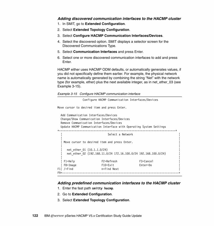
Adding discovered communication interfaces to the HACMP cluster1. In SMIT, go to Extended Configuration.
2. Select Extended Topology Configuration.
3. Select Configure HACMP Communication Interfaces/Devices.
4. Select the discovered option. SMIT displays a selector screen for the Discovered Communications Type.
5. Select Communication Interfaces and press Enter.
6. Select one or more discovered communication interfaces to add and press Enter.
HACMP either uses HACMP ODM defaults, or automatically generates values, if you did not specifically define them earlier. For example, the physical network name is automatically generated by combining the string “Net” with the network type (for example, ether) plus the next available integer, as in net_ether_03 (see Example 3-15).
Example 3-15 Configure HACMP communication interface
Configure HACMP Communication Interfaces/Devices
Move cursor to desired item and press Enter.
Add Communication Interfaces/Devices Change/Show Communication Interfaces/Devices Remove Communication Interfaces/Devices Update HACMP Communication Interface with Operating System Settings+--------------------------------------------------------------------------+ ¦ Select a Network ¦ ¦ ¦ ¦ Move cursor to desired item and press Enter. ¦ ¦ ¦ ¦ net_ether_01 (10.1.1.0/24) ¦ ¦ net_ether_02 (192.168.11.0/24 172.16.100.0/24 192.168.100.0/24) ¦ ¦ ¦ ¦ F1=Help F2=Refresh F3=Cancel ¦ ¦ F8=Image F10=Exit Enter=Do ¦F1¦ /=Find n=Find Next ¦F9+--------------------------------------------------------------------------+
Adding predefined communication interfaces to the HACMP cluster1. Enter the fast path smitty hacmp.
2. Go to Extended Configuration.
3. Select Extended Topology Configuration.
122 IBM Eserver pSeries HACMP V5.x Certification Study Guide Update
4. Select Configure HACMP Communication Interfaces/Devices and press Enter.
5. Select the predefined option. SMIT displays a selector screen for the Predefined Communications Type.
6. Select Communication Interfaces and press Enter. The Add a Communication Interface screen appears.
7. Fill in the fields as follows:
– Node name
The name of the node on which this network interface physically exists.
– Network name
A unique name for this logical network.
– Network interface
Enter the network interface associated with the communication interface (for example, en0).
– IP label/Address
The IP label/address associated with this communication interface, which will be configured on the network interface when the node boots. The picklist filters out IP labels/addresses already configured to HACMP.
– Network type
The type of network media/protocol (for example, Ethernet, token ring, fddi, and so on) Select the type from the predefined list of network types.
3.4.7 Defining communication devicesCommunication devices are already configured to AIX, and you have run the HACMP discovery program to add them to the HACMP picklists to aid in the HACMP configuration process.
Configuring discovered serial devices for the cluster1. Enter the fast path smitty hacmp.
2. Go to Extended Configuration.
3. Select Extended Topology Configuration.
Note: The network interface that you are adding has the base or service function by default. You do not specify the function of the network interface as in releases prior to HACMP V5.1, but further configuration defines the function of the interface.
Chapter 3. Installation and configuration 123

4. Select Configure HACMP Communication Interfaces/Devices and press Enter.
5. Select the discovered option and press Enter.
6. Select the Communications Devices type from the selector screen.
The screen Select Point-to-Point Pair of Discovered Communication Devices to Add appears. It displays a picklist that contains multiple communication devices, which, when you select one or more, are added to the HACMPadapter ODM class. Devices that are already added to the cluster are filtered from the picklist (see Example 3-16).
Example 3-16 Configure HACMP communication devices
Configure HACMP Communication Interfaces/Devices
Move cursor to desired item and press Enter.
Add Communication Interfaces/Devices +--------------------------------------------------------------------------+ ¦ Select Point-to-Point Pair of Discovered Communication Devices to Add ¦ ¦ ¦ ¦ Move cursor to desired item and press F7. Use arrow keys to scroll. ¦ ¦ ONE OR MORE items can be selected. ¦ ¦ Press Enter AFTER making all selections. ¦ ¦ ¦ ¦ # Node Device Device Path Pvid ¦ ¦ p630n01 tty0 /dev/tty0 ¦ ¦ p630n02 tty0 /dev/tty0 ¦ ¦ p630n03 tty0 /dev/tty0 ¦ ¦ p630n04 tty0 /dev/tty0 ¦ ¦ p630n05 tty0 /dev/tty0 ¦ ¦ p630n06 tty0 /dev/tty0 ¦ ¦ ¦ ¦ F1=Help F2=Refresh F3=Cancel ¦ ¦ F7=Select F8=Image F10=Exit ¦F1¦ Enter=Do /=Find n=Find Next ¦F9+--------------------------------------------------------------------------+
7. Select only two devices in this screen. It is assumed that these devices are physically connected, you are responsible for making sure this is true.
8. Continue defining devices as needed.
Configuring predefined communication devices for the cluster1. Enter the fast path smitty hacmp.
2. Go to Extended Configuration.
3. Select Extended Topology Configuration.
124 IBM Eserver pSeries HACMP V5.x Certification Study Guide Update

4. Select Configure HACMP Communication Interfaces/Devices and press Enter.
5. Select the predefined option and press Enter.
6. Select the Communications Devices type from the selector screen and press Enter. SMIT displays the Add a Communications Device screen.
7. Select the non IP-based network to which you want to add the devices and press Enter.
8. Enter the field values as follows:
– Node name
The node name for the serial device.
– Device name
A device file name. RS232 serial devices must have the device file name /dev/ttyn. Target mode SCSI serial devices must have the device file name /dev/tmscsin. Target mode SSA devices must have the device file name /dev/tmssan. Disk heartbeat serial devices have the name /dev/hdiskn. n is the number assigned in each device file name.
– Device path
For an RS232, for example, /dev/tty0.
– Network type
This field is automatically filled in (RS232, tmssa, tmscsi, or diskhb) when you enter the device name.
– Network name
This field is automatically filled in.
9. Press Enter after filling in all the required fields. HACMP now checks the validity of the device configuration. You may receive warnings if a node cannot be reached.
10.Repeat until each node has all the appropriate communication devices defined.
3.4.8 Boot IP labelsEvery node in a cluster is configured with an IP address on each of the avaliable adapters. These IP addresses are labeled as boot IP labels for a HACMP configuration. This IP labels are monitored by cluster for adapter alive status. If you have heartbeat over IP alias configured on the nodes, adapter availability is monitored via heartbeat IP labels.
Chapter 3. Installation and configuration 125

To see the boot IP labels on a node, you can run the following command:
# netstat -in
3.4.9 Defining persistent IP labelsA persistent node IP label is an IP alias that can be assigned to a network for a specified node.
A persistent node IP label is a label that:
� Always stays on the same node (is node-bound)
� Co-exists with other IP labels present on an interface
� Does not require installing an additional physical interface on that node
� Is not part of any resource group.
Assigning a persistent node IP label for a network on a node allows you to have a node-bound address on a cluster network that you can use for administrative purposes to access a specific node in the cluster.
The prerequisites to use persistent IP labels are:
� You can define only one persistent IP label on each node per cluster network.
� Persistent IP labels become available at a node’s boot time.
� On a non-aliased network, a persistent label may be defined on the same subnet as the service labels, or it may be placed on an entirely different subnet. However, the persistent label must be placed on a different subnet than all non-service IP labels on the network.
� On an aliased network, a persistent label may be placed on the same subnet as the aliased service label, or it may be configured on an entirely different subnet. However, it must be placed on a different subnet than all boot IP labels on the network.
� Once a persistent IP label is configured for a network interface on a particular network on a particular node, it becomes available on that node on a boot interface at the operating system boot time and remains configured on that network when HACMP is shut down on that node.
� You can remove a persistent IP label from the cluster configuration using the Delete a Persistent Node IP Label/Address SMIT screen. However, after the persistent IP label has been removed from the cluster configuration, it is not automatically deleted from the interface on which it was aliased. In order to completely remove the persistent IP label from the node, you should manually remove the alias with the ifconfig delete command or reboot the cluster node.
126 IBM Eserver pSeries HACMP V5.x Certification Study Guide Update
� Persistent node IP labels must be defined individually, without using the discovery process. Perform the following steps:
a. Enter the fast path smitty hacmp.
b. Go to Extended Configuration.
c. Select Extended Topology Configuration.
d. Select Configure HACMP Persistent Node IP Labels/Addresses.
e. Add a Persistent Node IP Label and press Enter.
f. Enter the field values as follows:
• Node name
The name of the node on which the IP label/address will be bound.
• Network name
The name of the network on which the IP label/address will be bound.
• Node IP label/Address
The IP label/address to keep bound to the specified node.
g. Press Enter.
3.4.10 Define HACMP network modulesAs explained before, HACMP has predefined networks with specific values. While configuring clusters for different types of networks, you must, at a certain point of time, change the predefined values of the network modules. If you want to see and change the network module values, HACMP V5.x’s SMIT menu can take you directly to the network modules menu.
If you want to see the current values of a network module, use the following procedure:
1. Enter smitty hacmp.
2. Go to Extended Configuration.
3. Select Configure HACMP Network Modules.
4. Select Change a Network Module and press Enter. SMIT displays a list of defined network modules (see Example 3-17).
5. Select the name of the network module for which you want to see current settings and press Enter.
Example 3-17 Change network module using predefined values
Change a Cluster Network Module using Pre-defined Values
Chapter 3. Installation and configuration 127
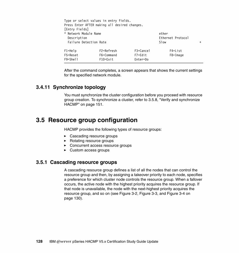
Type or select values in entry fields.Press Enter AFTER making all desired changes.[Entry Fields]* Network Module Name ether Description Ethernet Protocol Failure Detection Rate Slow +
F1=Help F2=Refresh F3=Cancel F4=ListF5=Reset F6=Command F7=Edit F8=ImageF9=Shell F10=Exit Enter=Do
After the command completes, a screen appears that shows the current settings for the specified network module.
3.4.11 Synchronize topologyYou must synchronize the cluster configuration before you proceed with resource group creation. To synchronize a cluster, refer to 3.5.8, “Verify and synchronize HACMP” on page 151.
3.5 Resource group configurationHACMP provides the following types of resource groups:
� Cascading resource groups� Rotating resource groups� Concurrent access resource groups� Custom access groups
3.5.1 Cascading resource groupsA cascading resource group defines a list of all the nodes that can control the resource group and then, by assigning a takeover priority to each node, specifies a preference for which cluster node controls the resource group. When a fallover occurs, the active node with the highest priority acquires the resource group. If that node is unavailable, the node with the next-highest priority acquires the resource group, and so on (see Figure 3-2, Figure 3-3, and Figure 3-4 on page 130).
128 IBM Eserver pSeries HACMP V5.x Certification Study Guide Update

Figure 3-2 Cascading resource group in initial configuration
Figure 3-3 Cascading resource group in fall-over condition
IP_1,VG_1FS_1
APP_SRV_1
ResourceGroup 1
NODE APriority=1
Status: Active
NODE BPriority=2
NODE CPriority=3
Status: Standby Status: Standby
IP_1,VG_1FS_1
APP_SRV_1
ResourceGroup 1
NODE APriority=1
Status: FAILED
NODE BPriority=2
NODE CPriority=3
Status: Active Status: Standby
Chapter 3. Installation and configuration 129

Figure 3-4 Cacading resource group in fall-back condition
The list of participating nodes establishes the resource chain for that resource group. When a node with a higher priority for that resource group joins or reintegrates into the cluster, it takes control of the resource group, that is, the resource group falls back from nodes with lesser priorities to the higher priority node.
Special cascading resource group attributesCascading resource groups support the following attributes:
� Cascading without fallback� Inactive takeover� Dynamic node priority
Cascading without fallback (CWOF) is a cascading resource group attribute that allows you to refine fall-back behavior. When the Cascading Without Fallback flag is set to false, this indicates traditional cascading resource group behavior: when a node of higher priority than that on which the resource group currently resides joins or reintegrates into the cluster, and interfaces are available, the resource group falls back to the higher priority node. When the flag is set to true, the resource group will not fall back to any node joining or reintegrating into the cluster, even if that node is a higher priority node. A resource group with CWOF configured does not require IP Address Takeover.
Inactive takeover is a cascading resource group attribute that allows you to fine-tune the initial acquisition of a resource group by a node. If inactive takeover is true, then the first node in the resource group to join the cluster acquires the resource group, regardless of the node’s designated priority. If Inactive Takeover
IP _1,V G _1FS _1
A P P _SR V_1
R esourceG roup 1
N O D E AP riority=1
S tatus: A ctive
N O D E BP riority=2
N O D E CP riority=3
S tatus: S tandby Status: S tandby
130 IBM Eserver pSeries HACMP V5.x Certification Study Guide Update
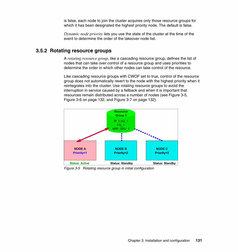
is false, each node to join the cluster acquires only those resource groups for which it has been designated the highest priority node. The default is false.
Dynamic node priority lets you use the state of the cluster at the time of the event to determine the order of the takeover node list.
3.5.2 Rotating resource groupsA rotating resource group, like a cascading resource group, defines the list of nodes that can take over control of a resource group and uses priorities to determine the order in which other nodes can take control of the resource.
Like cascading resource groups with CWOF set to true, control of the resource group does not automatically revert to the node with the highest priority when it reintegrates into the cluster. Use rotating resource groups to avoid the interruption in service caused by a fallback and when it is important that resources remain distributed across a number of nodes (see Figure 3-5, Figure 3-6 on page 132, and Figure 3-7 on page 132).
Figure 3-5 Rotating resource group in initial configuration
IP_1,VG_1FS_1
APP_SRV_1
ResourceGroup 1
NODE APriority=1
Status: Active
NODE BPriority=2
NODE CPriority=3
Status: Standby Status: Standby
Chapter 3. Installation and configuration 131
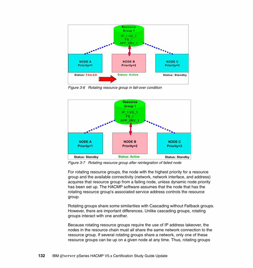
Figure 3-6 Rotating resource group in fall-over condition
Figure 3-7 Rotating resource group after reintegration of failed node
For rotating resource groups, the node with the highest priority for a resource group and the available connectivity (network, network interface, and address) acquires that resource group from a failing node, unless dynamic node priority has been set up. The HACMP software assumes that the node that has the rotating resource group's associated service address controls the resource group.
Rotating groups share some similarities with Cascading without Fallback groups. However, there are important differences. Unlike cascading groups, rotating groups interact with one another.
Because rotating resource groups require the use of IP address takeover, the nodes in the resource chain must all share the same network connection to the resource group. If several rotating groups share a network, only one of these resource groups can be up on a given node at any time. Thus, rotating groups
IP_1,VG_1FS_1
APP_SRV_1
ResourceGroup 1
NODE APriority=1
Status: FAILED
NODE BPriority=2
NODE CPriority=3
Status: Active Status: Standby
IP_1,VG_1FS_1
APP_SRV_1
ResourceGroup 1
NODE APriority=1
Status: Standby
NODE BPriority=2
NODE CPriority=3
Status: Active Status: Standby
132 IBM Eserver pSeries HACMP V5.x Certification Study Guide Update

distribute themselves. Cascading without Fallback groups, however, may clump together - that is, multiple groups will end up residing on the same node. CWOF does not require an IP address to be associated with the group.
3.5.3 Concurrent access resource groupsA concurrent access resource group may be shared simultaneously by multiple nodes. All nodes concurrently accessing a resource group acquire that resource group when they join the cluster. There are no priorities among nodes. Concurrent access resource groups are supported in clusters with up to 32 nodes. Note that all nodes in a cluster must be members of a concurrent resource group.
The only resources included in a concurrent resource group are volume groups with raw logical volumes, raw disks, and application servers that use the disks. The device on which these logical storage entities are defined must support concurrent access.
3.5.4 Custom resource groupsIn HACMP V5.1, in addition to cascading, rotating, and concurrent resource groups, you can configure custom resource groups. Parameters for custom resource groups let you precisely describe the resource group’s behavior at startup, fallover, and fallback.
The regular cascading, rotating, and concurrent resource groups have predefined startup, fall-over, and fall-back behaviors. The policies for custom resource groups are easier to understand than the CWOF or Inactive Takeover (IT) attributes. They are not restricted to the predefined policies of regular resource groups, and can be tailored to your needs.
Table 3-3 on page 134 presents the resource group behavior equivalency between “classic” resource groups (pre- HACMP 5.1) and custom resource groups.
Chapter 3. Installation and configuration 133
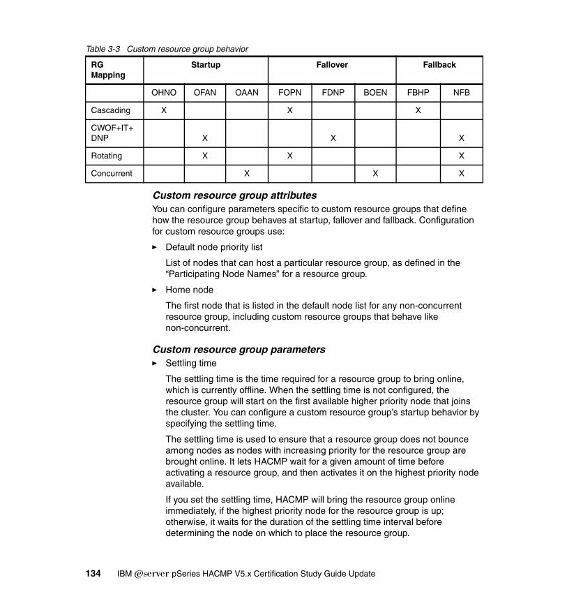
Table 3-3 Custom resource group behavior
Custom resource group attributesYou can configure parameters specific to custom resource groups that define how the resource group behaves at startup, fallover and fallback. Configuration for custom resource groups use:
� Default node priority list
List of nodes that can host a particular resource group, as defined in the “Participating Node Names” for a resource group.
� Home node
The first node that is listed in the default node list for any non-concurrent resource group, including custom resource groups that behave like non-concurrent.
Custom resource group parameters� Settling time
The settling time is the time required for a resource group to bring online, which is currently offline. When the settling time is not configured, the resource group will start on the first available higher priority node that joins the cluster. You can configure a custom resource group’s startup behavior by specifying the settling time.
The settling time is used to ensure that a resource group does not bounce among nodes as nodes with increasing priority for the resource group are brought online. It lets HACMP wait for a given amount of time before activating a resource group, and then activates it on the highest priority node available.
If you set the settling time, HACMP will bring the resource group online immediately, if the highest priority node for the resource group is up; otherwise, it waits for the duration of the settling time interval before determining the node on which to place the resource group.
RG Mapping
Startup Fallover Fallback
OHNO OFAN OAAN FOPN FDNP BOEN FBHP NFB
Cascading X X X
CWOF+IT+DNP X X X
Rotating X X X
Concurrent X X X
134 IBM Eserver pSeries HACMP V5.x Certification Study Guide Update

� Dynamic node priority (DNP)
You can configure a custom resource group’s fall-over behavior to use dynamic node priority.
� Delayed fallback timer
You can configure a custom resource group’s fallback behavior to occur at one of the predefined recurring times: daily, weekly, monthly, and yearly, or on a specific date and time, by specifying and assigning a delayed fallback timer.
The delayed fallback timer lets a custom resource group fall back to a higher priority node at a time that you specify. The resource group that has a delayed fallback timer configured and that currently resides on a non-home node falls back to the higher priority node at the specified time.
� Inactive takeover (IT)
You can configure a custom resource group’s startup behavior in such a way that if the RG is in “offline” state, and if one node that is part of the RG node priority list starts the HACMP services, it can acquire that resource group.
3.5.5 Configuring HACMP resource groups using the standard pathUsing the standard path, you can configure resource groups that use the basic management policies. These policies are based on the three predefined types of startup, fall-over, and fall-back policies: cascading, rotating, and concurrent.
Configuring a resource group involves two phases:
� Configuring the resource group name, management policy, and the nodes that can own it.
� Adding the resources and additional attributes to the resource group.
Creating HACMP resource groups using the standard pathTo create a resource group, perform the following steps:
1. Enter the fast path smitty hacmp.
2. On the HACMP menu, select Initialization and Standard Configuration.
3. Select Configure HACMP Resource Groups.
4. Select Add a Standard Resource Group and press Enter.
5. You are prompted to select a resource group management policy. Select Cascading, Rotating, Concurrent, or Custom and press Enter.
Note: Dynamic node priority can also be configured for regular cascading and rotating resource groups.
Chapter 3. Installation and configuration 135

Depending on the previous selection, you will see a screen titled Add a Cascading/Rotating/Concurrent/Custom Resource Group. The screen will only show options relevant to the type of the resource group you selected.
6. Enter the field values as follows (this screen is used for cascading, rotating, and concurrent resource groups):
– Resource group name
Enter the desired name. Use no more than 31 alphanumeric characters or underscores; do not use a leading numeric.
– Participating node names
Enter the names of the nodes that can own or take over this resource group. Enter the node with the highest priority for ownership first, followed by the nodes with the lower priorities, in the desired order (see Example 3-18).
Example 3-18 Resource group configuration using the standard path
Add a Resource Group with a Cascading Management Policy (standard)
Type or select values in entry fields.Press Enter AFTER making all desired changes.
[Entry Fields]* Resource Group Name [rg1]* Participating Node Names (Default Node Priority) [p630n01 p630n02]
F1=Help F2=Refresh F3=Cancel F4=ListF5=Reset F6=Command F7=Edit F8=ImageF9=Shell F10=Exit Enter=Do
7. Press Enter.
8. Press F3 to return to the Add a Standard Resource Group screen to continue adding all the standard resource groups you have planned for the HACMP cluster.
Note: If you are configuring a custom resource group, see 3.5.4, “Custom resource groups” on page 133.
136 IBM Eserver pSeries HACMP V5.x Certification Study Guide Update

Assigning resources to resource groupsTo assign the resources for a resource group, perform the following steps:
1. Enter the fast path smitty hacmp.
2. Go to Initialization and Standard Configuration.
3. Select Configure HACMP Resource Groups.
4. Select Change/Show Resources for a Standard Resource Group and press Enter to display a list of defined resource groups.
5. Select the resource group you want to configure and press Enter. SMIT returns the screen that matches the type of resource group you selected, with the Resource Group Name and Participating Node Names (Default Node Priority) fields filled in (see Example 3-19).
Example 3-19 Assign resource to resource group
Change/Show Resources for a Cascading Resource GroupType or select values in entry fields.Press Enter AFTER making all desired changes.
[Entry Fields] Resource Group Name rg01 Participating Node Names (Default Node Priority) p630n01 p630n02 p630n>
* Service IP Labels/Addresses [n01a1] + Volume Groups [] + Filesystems (empty is ALL for VGs specified) [] + Application Servers [] +
F1=Help F2=Refresh F3=Cancel F4=ListF5=Reset F6=Command F7=Edit F8=ImageF9=Shell F10=Exit Enter=Do
6. Enter the field values as follows:
– Service IP label/IP address
List the service IP labels to be taken over when this resource group is taken over. Press F4 to see a list of valid IP labels. These include addresses that rotate or may be taken over.
– Filesystems (empty is for all specified VGs)
If you leave the Filesystems field blank and specify the shared volume groups in the Volume Groups field below, all file systems will be mounted in the volume group. If you leave the Filesystems field blank and do not specify the volume groups in the field below, no file systems will be mounted. You may also select individual file systems to include in the
Chapter 3. Installation and configuration 137

resource group. Press F4 to see a list of the file systems. In this case, only the specified file systems will be mounted when the resource group is brought online.
Filesystems is a valid option only for non-concurrent resource groups.
– Volume groups
Identify the shared volume groups that should be varied on when this resource group is acquired or taken over. Choose the volume groups from the picklist or enter desired volume groups names in this field.
Pressing F4 will give you a list of all shared volume groups in the resource group and the volume groups that are currently available for import onto the resource group nodes.
– Concurrent volume groups
Identify the shared volume groups that can be accessed simultaneously by multiple nodes. Choose the volume groups from the picklist, or enter the desired volume groups names in this field. If you previously requested that HACMP collect information about the appropriate volume groups, then pressing F4 will give you a list of all existing concurrent capable volume groups that are currently available in the resource group and concurrent capable volume groups available to be imported onto the nodes in the resource group.
Disk fencing is turned on by default.
– Application servers
Indicate the application servers to include in the resource group. Press F4 to see a list of application servers.
7. Press Enter to add the values to the HACMP ODM.
8. Press F3 until you return to the Change/Show Resources for a Standard Resource Group menu, or F10 to exit SMIT.
Note: The Service IP Label/IP Addresses, Filesystems, and Volume group options are used only if you are adding a non-concurrent or custom non-concurrent-like resource groups.
138 IBM Eserver pSeries HACMP V5.x Certification Study Guide Update
3.5.6 Configure HACMP resource group with extended pathTo create a resource group using the Extended path, perform the following steps:
1. Enter the fast path smitty hacmp.
2. Go to Extended Configuration.
3. Select Extended Resource Configuration.
4. Select HACMP Resource Group Configuration.
5. Select Add a Resource Group and press Enter.
6. On the next screen, select a resource group management policy (Cascading, Rotating, Concurrent, or Custom) and press Enter.
Depending on the previous selection, you will see a screen titled Add a Cascading/Rotating/Concurrent/Custom Resource Group. The screen will only show options relevant to the type of the resource group you selected.
7. Enter the field values as follows (this screen is used for cascading, rotating, and concurrent resource groups):
– Resource group name
Enter the desired name. Use no more than 31 alphanumeric characters or underscores; do not use a leading numeric.
– Inter-site management policy
Select one of the following options:
• Ignore (default) should be used unless sites are defined. If you define sites, appropriate methods or customization must be provided to handle site operations. Site policy set to anything but Ignore automatically adds the resource group to a custom serial processing list.
• Cascading resources may be assigned to be taken over by multiple sites in a prioritized manner. When a site fails, the active site with the highest priority acquires the resource. When the failed site rejoins, the site with the highest priority acquires the resource.
• Rotating resources may be acquired by any site in its resource chain. When a site fails, the resource will be acquired by the highest priority standby site. When the failed node rejoins, the resource remains with its new owner.
Note: If you are configuring a custom resource group, see 3.5.7, “Configuring custom resource groups” on page 145.
Chapter 3. Installation and configuration 139

• Concurrent resources may be accessed from any site. If the site relationship is concurrent, the management policy cannot be rotating.
– Participating node names
Enter the names of the nodes that can own or take over this resource group. Enter the node with the highest priority for ownership first, followed by the nodes with the lower priorities, in the desired order.
8. Press Enter.
9. Press F3 to return to the Add a Standard Resource Group screen to continue adding all the standard resource groups you have planned for the HACMP cluster (see Example 3-20).
Example 3-20 Resource group configuration using extended path
Add a Cascading Resource Group (extended)Type or select values in entry fields.Press Enter AFTER making all desired changes.
[Entry Fields]* Resource Group Name [rg1]* Inter-Site Management Policy [ignore] +* Participating Node Names (Default Node Priority) [p630n01 p630n02] +
F1=Help F2=Refresh F3=Cancel F4=ListF5=Reset F6=Command F7=Edit F8=ImageF9=Shell F10=Exit Enter=Do
Assign resources and attributes to resource group by extended pathTo configure resources and attributes for a resource group, perform the following steps:
1. Enter the fast path smitty hacmp.
2. Go to Extended Configuration.
3. Select Extended Resource Configuration.
4. Select Extended Resource Group Configuration.
5. Select Change/Show Resources and Attributes for a Resource Group and press Enter. SMIT displays a list of defined resource groups.
6. Select the resource group you want to configure and press Enter. SMIT returns the screen that matches the type of resource group you selected, with the Resource Group Name, Inter-site Management Policy, and Participating Node Names (Default Node Priority) fields filled in.
140 IBM Eserver pSeries HACMP V5.x Certification Study Guide Update

If the participating nodes are powered on, you can press F4 to list the shared resources. If a resource group/node relationship has not been defined, or if a node is not powered on, F4 displays the appropriate warnings (see Example 3-21).
Example 3-21 Assigning resource and attributes to resource group using extended path
Change/Show All Resources and Attributes for a Cascading Resource GroupType or select values in entry fields.Press Enter AFTER making all desired changes.[Entry Fields] Resource Group Name rg01 Resource Group Management Policy cascading Inter-site Management Policy ignore Participating Node Names (Default Node Priority) p630n01 p630n02> Dynamic Node Priority (Overrides default) [] Inactive Takeover Applied false Cascading Without Fallback Enabled falseApplication Servers [] Service IP Labels/Addresses [n01a1] Volume Groups [] Use forced varyon of volume groups, if necessary false Automatically Import Volume Groups false Filesystems (empty is ALL for VGs specified) [] Filesystems Consistency Check fsck Filesystems Recovery Method sequential Filesystems mounted before IP configured false Filesystems/Directories to Export [] Filesystems/Directories to NFS Mount [] Network For NFS Mount []
Tape Resources [] Raw Disk PVIDs []
Fast Connect Services [] Communication Links []
Primary Workload Manager Class [] Secondary Workload Manager Class []
Miscellaneous Data []F1=Help F2=Refresh F3=Cancel F4=ListF5=Reset F6=Command F7=Edit F8=ImageF9=Shell F10=Exit Enter=Do
Chapter 3. Installation and configuration 141

7. Fill in the following fields:
– Dynamic node priority (Overrides default)
Select the dynamic node priority policy. The default is blank (the ordered node list). All defined dynamic node priority policies are listed, including the preconfigured policies.
– Service IP label/IP addresses
This option is the same as used in a standard configuration path.
– Filesystems (empty is all for specified VGs)
This option is the same as used in the standard configuration path.
– Volume groups
This option is the same as used in the standard configuration path.
– Application servers
This option is the same as used in the standard configuration path.
– Use forced varyon of volume groups, if necessary
The default is false. If this flag is set to true, HACMP uses a forced varyon to bring each volume group that belongs to this resource group online in the event that a normal varyon for the volume group fails due to a lack of quorum, and if HACMP finds at least one complete copy of every logical partition in every logical volume available for this volume group.
This option should only be used for volume groups in which every logical volume is mirrored. We recommend using the super strict allocation policy; forced varyon is unlikely to be successful for other choices of logical volume configuration.
– Filesystems consistency check
Identify the method to check consistency of file systems: fsck (default) or logredo (for fast recovery).
– Filesystems recovery method
Identify the recovery method for the file systems: parallel (for fast recovery) or sequential (default). Do not set this field to parallel if you have shared, nested file systems. These must be recovered sequentially.
Note: The cluster verification utility, clverify, does not report file system and fast recovery inconsistencies.
142 IBM Eserver pSeries HACMP V5.x Certification Study Guide Update

– File systems mounted before IP configured
Specify whether, on takeover, HACMP takes over volume groups and mounts a failed node’s file systems before or after taking over the failed node's IP address or addresses. The default is false, meaning the IP address is taken over first. Similarly, upon reintegration of a node, the IP address is acquired before the file systems. Set this field to true if the resource group contains file systems to export. This is so that the file systems will be available once NFS requests are received on the service address.
– Filesystems/Directories to export
Identify the file systems or directories to be NFS exported. The file systems should be a subset of the file systems listed in Filesystems fields above. The directories should be contained in one of the file systems listed above. Press F4 for a list.
– Filesystems/Directories to NFS mount
Identify the file systems or directories to NFS mount. All nodes in the resource chain will attempt to NFS mount these file systems or directories while the owner node is active in the cluster.
– Network for NFS mount (Optional)
Choose a previously defined IP network where you want to NFS mount the file systems. The F4 key lists valid networks. This field is relevant only if you have filled in the Filesystems/Directories to NFS Mount field. The Service IP Labels/IP Addresses field should contain a service label that is on the network you choose.
– Raw disk PVIDs
Press F4 for a listing of the PVIDs and associated hdisk device names. If you are using an application that directly accesses raw disks, list the raw disks here.
– Tape resources
Enter the tape resources that you want started on the resource group. Press F4 to choose from a list of resources previously defined in the Define Tape Resources screen.
– Fast connect services
Press F4 to choose from a list of Fast Connect resources common to all nodes in the resource group, specified during the initial configuration of Fast Connect. If you are adding Fast Connect fileshares, make sure you have defined their file systems in the resource group.
Chapter 3. Installation and configuration 143

– Communication links
Enter the communication links (defined previously in the Configure Communication Adapters and Links SMIT screens) to be started by HACMP. Press F4 to see a list of defined communication links. If adding SNA-over-LAN links, make sure you have also added a service IP label to the resource group.
– Miscellaneous
Specify text you want to place into the topology, along with the resource group information. It is accessible by the scripts, for example, Database1.
– Primary workload manager class
Press F4 and choose from the picklist of Workload Manager classes associated with the HACMP WLM configuration specified. For cascading resource groups, if no secondary WLM class is specified, all nodes use the primary WLM class. If a secondary class is specified, only the primary node uses the primary WLM class. For rotating and concurrent resource groups, all nodes in the resource group are configured to use the primary WLM class.
– Secondary workload manager class
(Optional) Press F4 and choose from the picklist of Workload Manager class associated with this resource group. Only cascading resource groups are allowed to use secondary WLM classes. If no secondary WLM class is specified, all nodes in the resource group use the primary WLM class. If you specify a secondary class here, the primary node uses the primary WLM class and all other nodes use the secondary WLM class.
– Automatically import volume groups
Specifies whether HACMP should automatically import those volume groups that are defined in the Volume Groups or Concurrent Volume Groups fields. By default, the Automatically Import Volume Groups flag is set to false. If Automatically Import Volume Groups is set to false, then selected volume groups will not be imported automatically. In this case, when you add volume groups to the resource group, make sure that the selected volume groups have already been imported to each of the nodes using the importvg command or C-SPOC. If Automatically Import Volume Groups is set to true, then when you press Enter, HACMP determines whether the volume group that you entered or selected in the Volume Groups or Concurrent Volume Groups fields needs to be imported to any of the nodes in the resource group, and automatically imports it, if needed.
144 IBM Eserver pSeries HACMP V5.x Certification Study Guide Update

– Inactive takeover applied
Set this variable to control the initial acquisition of a cascading resource group. This variable does not apply to rotating or concurrent resource groups. If Inactive Takeover is true, then the first node in the resource group to join the cluster acquires the resource group, regardless of the node’s designated priority. If Inactive Takeover is false, each node to join the cluster acquires only those resource groups for which it has been designated the highest priority node. The default is false.
– Cascading without fallback enabled
Set this variable to determine the fall-back behavior of a cascading resource group. When the CWOF variable is false, a cascading resource group will fall back as a node of higher priority joins or reintegrates into the cluster. When CWOF is true, a cascading resource group will not fall back as a node of higher priority joins or reintegrates into the cluster. It migrates from its owner node only if the owner node fails. It will not fall back to the owner node when the owner node reintegrates into the cluster. The default for CWOF is false.
– Fallback timer policy (empty is immediate)
This field displays only if this is a custom resource group and you have previously selected Fallback to Higher Priority Node in the List as a fall-back policy. The default is blank (the resource group falls back immediately after a higher priority node joins). All configured fall-back timer policies are listed in the picklist.
8. Press Enter to add the values to the HACMP ODM.
9. Return to the top of the Extended Configuration menu and synchronize the cluster.
3.5.7 Configuring custom resource groupsIn addition to resource groups based on the basic management policies (cascading, rotating, and concurrent), you can configure custom resource groups.
When you are using the Extended Configuration path, you can specify parameters that precisely describe the custom resource group’s behavior at startup, fallover, and fallback, including delayed fall-back timers (these attributes are not available on the Standard Configuration path). For custom RG behavior, see Table 3-3 on page 134.
Make sure that you can always configure a custom resource group that would behave exactly as a predefined cascading, rotating, or concurrent resource
Chapter 3. Installation and configuration 145

group by selecting the policies that are identical to the behavior of the particular predefined resource group.
To configure a custom resource group, you must perform the following steps:
� Configure the run-time policies.
� Configure a dynamic node priority policy.
� Configure a delayed fall-back timer.
� Configure a settling time.
� Define a startup behavior.
� Define a fall-over behavior.
� Define a fall-back behavior.
� Add resources to the custom resource group.
Configure a custom resource groupPerform the following steps:
1. Enter the fast path smitty hacmp.
2. Go to Extended Configuration.
3. Select Extended Resource Configuration.
4. Select HACMP Resource Group Configuration → Add a Resource Group and press Enter. A picklist displays all the types of resource groups you can configure: Cascading, Rotating, Concurrent, or Custom.
5. Select Custom from the picklist and press Enter. The Add a Resource Group screen appears. Fill in the fields as follows:
– Resource group name
Enter the desired name. Use no more than 31 alphanumeric characters or underscores; do not use a leading numeric.
– Inter-site management policy
The default is Ignore. This is the only valid option for custom resource groups.
– Participating node names
Enter the names of the nodes that can own or take over this resource group. Enter the node with the highest priority for ownership first, followed by the nodes with the lower priorities, in the desired order.
146 IBM Eserver pSeries HACMP V5.x Certification Study Guide Update

– Startup policy
Select a value from the list that defines the startup policy of the custom resource group:
• Online on home node only
The custom resource group should be brought online only on its home (highest priority) node during the resource group startup. This requires the highest priority node to be available.
• Online on first available node
The custom resource group activates on the first participating node that becomes available. If you have configured the settling time for custom resource groups, it will only be used for this resource group if you use this startup policy option.
• Online on all available nodes
The custom resource group is brought online on all nodes. If you select this option for the resource group, ensure that resources in this group can be brought online on multiple nodes simultaneously.
– Fallover policy
Select a value from the list that defines the fall-over policy of the custom resource group:
• Fallover to next priority node in the list
In the case of fallover, the resource group that is online on only one node at a time follows the default node priority order specified in the resource group’s nodelist.
• Fallover using dynamic node priority
Before selecting this option, configure a dynamic node priority policy that you want to use. Or you can choose one of the three predefined dynamic node priority policies.
• Bring offline (On error node only)
Select this option to bring a resource group offline on a node during an error condition. This option is most suitable when you want to ensure that if a particular node fails, the resource group goes offline on that node only but remains online on other nodes. Selecting this option as the fall-over preference when the startup preference is not Online On All Available Nodes may allow resources to become unavailable during error conditions. If you do so, HACMP issues a warning.
Chapter 3. Installation and configuration 147

– Fallback policy
Select a value from the list that defines the fall-back policy of the custom resource group:
• Fallback to higher priority node in the list
A resource group falls back when a higher priority node joins the cluster. If you select this option, then you can use the delayed fall-back timer that you previously specified in the Configure Resource Group Run-time Policies SMIT menu. If you do not configure a delayed fallback policy, the resource group falls back immediately when a higher priority node joins the cluster.
• Never fallback
A resource group does not fall back when a higher priority node joins the cluster.
6. Press Enter to add the resource group information to the HACMP ODM.
7. Press F3 after the command completes until you return to the Extended Resource configuration screen, or F10 to exit SMIT.
Configuring a settling time for custom resource groupThe settling time specifies how long HACMP waits for a higher priority node (to join the cluster) to activate a custom resource group that is currently offline on that node. If you set the settling time, HACMP waits for the duration of the settling time interval to see if a higher priority node may join the cluster, rather than simply activating the resource group on the first possible node that reintegrates into the cluster.
To configure a settling time for custom resource groups, perform the following steps:
1. Enter the fast path smitty hacmp.
2. Go to Extended Configuration.
3. Select Extended Resource Configuration.
4. Select Configure Resource Group Run-Time Policies.
5. Select Configure Settling Time for Resource Group and press Enter. The Configure Settling Time screen appears.
6. Enter field values as follows:
– Settling time (in seconds)
Enter any positive integer number in this field. The default is zero. In this case, the resource group does not wait before attempting to start on a joining higher priority node. If you set the settling time, then if the currently
148 IBM Eserver pSeries HACMP V5.x Certification Study Guide Update

available node that reintegrated into the cluster is not the highest priority node, the resource group waits for the duration of the settling time interval. When the settling time expires, the resource group gets activated on the node that has the highest priority among the list of nodes that joined the cluster during the settling time interval. If no nodes joined the cluster, the resource group remains offline. The settling time is only valid for custom resource groups that have the Online on First Available Node startup policy.
7. Press Enter to commit the changes and synchronize the cluster. This settling time is assigned to all custom resource groups with the Online on First Available Node startup policy.
Defining delayed fall-back timersA delayed fall-back timer lets a custom resource group fall back to its higher priority node at a specified time. This lets you plan for outages for maintenance associated with this resource group.
You can specify a recurring time at which a custom resource group will be scheduled to fall back, or a specific time and date when you want to schedule a fallback to occur.
You can specify the following types of delayed fall-back timers for a custom resource group:
� Daily� Weekly� Monthly� Yearly� On a specific date
Configuring delayed fall-back timersTo configure a delayed fall-back timer, perform the following steps:
1. Enter smit hacmp.
2. Select Extended Configuration → Extended Resource Configuration → Configure Resource Group Run-Time Policies → Configure Delayed Fallback Timer Policies → Add a Delayed Fallback Timer Policy and press Enter. A picklist Recurrence for Fallback Timer displays. It lists Daily, Weekly, Monthly, Yearly, and Specific Date policies.
3. Select the timer policy from the picklist and press Enter. Depending on which option you choose, a corresponding SMIT screen displays that lets you configure this type of a fall-back policy.
Chapter 3. Installation and configuration 149

Assigning a delayed fall-back policy to a custom resource groupYou must define the delayed fall-back policies before you can assign them as attributes to custom resource groups.
To assign a delayed fallback policy to a custom resource group, perform the following steps:
1. Create a custom resource group, or select an existing custom resource group.
2. Go to Extended Configuration → Change/Show Resource and Attributes for a Resource Group and press Enter. SMIT displays a list of resource groups.
3. Select the resource group for which you want to assign a delayed fall-back policy. (All valid options for the resource group are displayed based on the startup, fall-over, and fall-back preferences that you have specified for the custom resource group.)
4. Enter field values as follows:
– Resource Group Name
The name of the selected resource group displays here.
– Inter-site Management Policy
Ignore (default) is used for custom resource groups.
– Participating Node Names (Default Node Priority)
The names of the nodes that can own or take over this resource group. The node with the highest priority is listed first, followed by the nodes with the lower priorities.
– Dynamic Node Priority (Overrides default)
The default is blank (the ordered node list). All defined dynamic node priority policies are listed, including the preconfigured policies. Note that this SMIT option displays only if you have previously selected Fallover Using Dynamic Node Priority as a fall-over behavior for this resource group.
– Fallback Timer Policy (empty is immediate)
The default is blank (the resource group falls back immediately after a higher priority node joins). All configured fall-back timer policies are listed in the picklist. Note that this SMIT option displays only if you have previously selected Fallback to Higher Priority Node in the List as a fall-back policy for this resource group.
5. Press the F4 key to see the picklist in the Fallback Timer Policy field and select the fall-back timer policy you want to use for this resource group.
150 IBM Eserver pSeries HACMP V5.x Certification Study Guide Update
6. Press Enter to commit the changes. The configuration is checked before populating the ODM. You can assign the same fall-back timer policy to other custom resource groups.
7. Assign fall-back timer policies to other custom resource groups and synchronize the cluster when you are done.
3.5.8 Verify and synchronize HACMPAfter you configure, reconfigure, or update a cluster, you should run the cluster verification procedure on one node to check that all nodes agree on the cluster topology, network configuration, and the ownership and takeover of HACMP resources. If the verification is successful, the configuration is synchronized. Synchronization takes effect immediately on an active cluster.
Cluster verification consists of a series of checks performed against various HACMP configurations. Each check tries to detect either a cluster consistency issue or n error. The messages output by the clverify utility follow a common, standardized format where feasible, indicating the node(s), devices, command, and so on, in which the error occurred. The utility uses verbose logging to write to /var/hacmp/clverify/clverify.log.
After making a change to the cluster, you can verify the cluster configuration or only the changes made to the cluster since the last successful verification was run. The clverify utility also keeps a detailed record of the information in the ODMs on each of the nodes after it runs. Subdirectories for each node contain information for the last successful verification, the next-to-last successful verification, and the last unsuccessful verification.
On the node where you run the utility, the /var/hacmp/clverify/pass | pass.prev | fail /nodename/clver_response.xml file contains the information retrieved from all the nodes. Here you can see the detailed information regarding the data collected and the checks performed. You (or a service technician) can look at the details of the unsuccessful verification log to see exactly where the errors are.
Verifying and synchronizing the cluster configurationThe procedure is a bit different depending on which SMIT path you are using. If you are using the Initialization and Standard Configuration path, when you select the option Verify and Synchronize HACMP Configuration, the command is immediately executed. Messages are sent to the console as the configuration is checked.
Note: The /var/hacmp/clverify/clverify.log files (0-9) typically consume 1-2 MB of disk space. For example, for a four node cluster, we recommend that the /var file system have at least 18 MB of free space.
Chapter 3. Installation and configuration 151

If you are using the Extended Configuration path, you can set parameters for the command before it runs. These parameters differ somewhat depending on whether or not the cluster is active.
Complete the following steps to verify and synchronize the cluster topology and resources configuration:
1. Enter the fast path smitty hacmp.
2. Go to Extended Configuration.
3. Select Extended Verification and Synchronization and press Enter.
The software checks whether cluster services are running on any cluster node. If the cluster is active, you have the choice to run an emulation or an actual verification process. The Extended Cluster Verification and Synchronization SMIT screen includes the following options for an active cluster:
– Emulate or Actual
Actual is the default.
– Force synchronization if verification fails?
No is the default. If you select Yes, cluster verification runs, but verification errors are ignored and the cluster is synchronized.
– Verify changes only?
No is the default. (Run the full check on resource and topology configuration.) Yes specifies to verify only resource or topology configurations that have changed since the last time the cluster was verified.
– Logging
Standard is the default. Choosing Verbose sends output to the console that is normally only logged in the clverify.log. Verbose logging is always turned on when clverify is collecting data from remote nodes.
The SMIT screen for an inactive cluster includes the following options:
– Verify, Synchronize, or Both?
Both is the default. You can also elect to verify only or to synchronize only.
– Force synchronization if verification failed?
No is the default. If you select Yes, cluster verification runs, but verification errors are ignored and the cluster is synchronized.
– Verify only changed parameters?
No is the default. (Run the full check on resource and topology configuration.) Yes specifies to verify only resource or topology
152 IBM Eserver pSeries HACMP V5.x Certification Study Guide Update

configurations that have changed since the last time the cluster was verified.
– Logging
Standard is the default. Choosing Verbose sends output to the console normally only logged in the clverify.log. Verbose logging is always turned on when clverify is collecting data from remote nodes.
4. Select the verification mode to use:
Select the defaults for all fields to run all the verification checks that apply to the current cluster configuration. The cluster will only be synchronized if there are no errors.
Select Force if you want to ignore verification errors and synchronize the cluster.
Select Verify Changes Only to run only those checks related to the parts of the HACMP configuration that you have changed (and synchronized). This mode has no effect on an inactive cluster.
5. Press Enter. SMIT runs the clverify utility. The output from the verification is displayed in the SMIT Command Status window.
6. If you receive error messages, make the necessary changes and run the verification procedure again.
Note: The Verify Changes Only option only relates to HACMP cluster ODMS. If you have made changes to the AIX configuration on your cluster nodes, you should not select this option. Only select this option if you have made no changes to the AIX configuration.
Chapter 3. Installation and configuration 153

3.6 ReviewThis section contains a quiz about the topics discussed in this chapter and is intended for self verification. These questions are provided as is, and are not sample exam questions.
3.6.1 Sample questions1. Which is the recommended method to install HACMP V5.x LPPs on the
nodes for a five node cluster?
a. Installation via media.
b. Installation via NIM.
c. Installation via hard disk.
d. Installation via NFS.
2. Choose the appropriate way of migrating HACMP V4.4.1 HAS to HACMP V5.x?
a. Snapshot conversion from HACMP V4.4.1 to HACMP V5.x.
b. Uninstall HACMP V4.4.1 and Reinstall HACMP V5.x.
c. Migrate HACMP V4.4.1 to HACMP V4.5 and then migrate to HACMP V5.x.
d. Uninstall HACMP V4.4.1 and Reinstall HACMP V4.5 and then migrate to HACMP V5.x.
3. Which is the name of the utility provided for converting an HACMP V4.X snapshot when migrating to HACMP V5.x?
a. /usr/es/sbin/cluster/install/cl_convert.
b. /usr/es/sbin/cluster/utilities/clconvert_snapshot.
c. /usr/es/sbin/cluster/bin/clconvert_snapshot.
4. Which version of HACMP is supported for node by node migration to HACMP V5.x?
a. HACMP V4.4.1.
b. HACMP V4.3.1.
c. HACMP V4.5.
d. HACMP/ES 4.4.1.
154 IBM Eserver pSeries HACMP V5.x Certification Study Guide Update

5. If for some reason, you decide not to complete the migration process, which is the best regression procedure to get back to previous version?
a. Node by node backward migration.
b. Restore a previously created system backup.
c. Uninstall HACMP V5.x, install HACMP V4.X, and restore the previously created snapshot.
6. Which is the lowest version of HACMP supported for upgrade to HACMP V5.x?
a. 4.2.
b. 4.3.
c. 4.4.
d. 4.5.
7. What is the AIX version that supports fast disk takeover in an HACMP V5.x cluster?
a. AIX 5L V5.1.
b. AIX 5L V5.1 ML1.
c. AIX 5L V5.1 ML3.
d. AIX 5L V5.2 ML1.
8. What is the name of the new SMIT configuration path for a quick setup of an HACMP V5.x cluster?
a. Enhanced.
b. Extended.
c. Standard.
d. EZ.
9. In HACMP V5.x, can an enhanced concurrent volume group be used to define a shared file system?
a. Yes.
b. Yes, if the file system will not be exported via NFS.
c. No, because the concurrent volume group option does not support creation of file systems.
d. Yes, only if the file system is jfs2.
Chapter 3. Installation and configuration 155

10.What parameter is used by HACMP to varyon a volume group used for fast disk takeover on the node that acquires the resource group?
a. Non-concurrent.
b. Concurrent.
c. Concurrent active.
d. Concurrent passive.
11.If you need to configure IPAT via replacement mechanism, which SMIT configuration path you need to use?
a. Standard.
b. Easy.
c. Enhanced.
d. Extended.
12.Which facility is used by HACMP to provide configuration information for existing nodes?
a. Auto discovery.
b. Manual discovery.
c. Config manager.
13.Which parameter would prevent a resource group fallback from bouncing if multiple nodes join the cluster at the same time?
a. Priority override location (POL).
b. Cascading without fallback (CWOF).
c. Fall-back timer.
d. Settling Time.
14.What disk parameter should be used when assigning a raw physical disk to a resource group?
a. Volume group name.
b. VPATH ID.
c. Physical Volume ID (PVID).
d. Logical unit number ID (LUN).
156 IBM Eserver pSeries HACMP V5.x Certification Study Guide Update

15.In which type of resource group we can configure the Delayed Fallback Timer parameter in HACMP V5.1?
a. Cascading.
b. Concurrent.
c. Custom.
d. Rotating.
16.Which startup policy for a custom resource group is similar to a concurrent resource group?
a. Online on first available node.
b. Online on home node only.
c. Online on all available nodes.
17.Which fall-over policy for a custom resource group is similar to a concurrent resource group?
a. Fall back to next available node using dynamic node priority.
b. None.
c. Fall over to the lowest priority node.
18.When you perform the cluster verification and synchronization, which log file is generated/updated?
a. /tmp/hacmp.out.
b. /var/hacmp/clverify/clverify.log.
c. /tmp/clverify.log.
d. /usr/es/adm/cluster.log.
19.Which services are required to run for an active HACMP V5.1 cluster?
a. topsvcs, emaixos, and clinfo.
b. topsvcs, grpsvcs, emsvcs, and clcomdES.
c. topsvcs, grpsvcs, emaixos, emsvcs, and clstmgrES.
d. grpsvcs, ctrmc, clcomdES, and clstmgrES.
20.Which log files should be check for “node_down” and “node_down_complete” events?
a. /usr/es/adm/cluster.log and /tmp/hacmp.out.
b. /tmp/hacmp.out.1 and /var/ha/clstmgr.log.
c. /var/hacmp/clverify/clverify.log and /tmp/cluster.debug.
Chapter 3. Installation and configuration 157

Answers to the quiz can be found in Appendix A, “ITSO sample cluster” on page 285.
158 IBM Eserver pSeries HACMP V5.x Certification Study Guide Update

Chapter 4. Cluster verification and testing
Verification and testing is the very essence of a reliable configuration and one of the cornerstones of a successful implementation. Most system administrators remember their last HACMP implementation either because it was extremely stressful or, hopefully, because everything went as expected.
A HACMP cluster is as good as you have designed, implemented, and tested it. Even though HACMP is a powerful component, without the proper tests, it can be a disaster when implemented. Unscheduled takeovers, faulty scripts, nodes that mysteriously halt, and general downtime could be the side effects of an untested cluster configuration. Try to list as many failure scenarios as you can, create a test plan, verify your cluster behavior in all failure cases, and then carefully review your cluster planning and ensure that you eliminated any single point of failure.
Throughout this chapter, we walk through some of the basic testing procedures. Keep in mind that high availability does not only include HACMP software, but also appropriate hardware, reliable software, a well documented design, advanced customizing, administration, and change management.
4
© Copyright IBM Corp. 2004, 2006. All rights reserved. 159

4.1 Will it all work?It is one thing is to design and install HACMP, but another thing entirely to have it to work the way you expect. There is only one way to find out if it will work as expected: test, verify, and validate. Keep in mind that once the cluster is running, production changes are much harder to accomplish, if possible at all.
Testing and validation might vary according to the cluster solution you choose; however, we cannot emphasize enough that testing is probably the most important part of the entire implementation, as more testing equals better results. Try to simulate every incident you can possible imagine; the configuration will only be as good as you have tested it to be.
We have tried to highlight some of the points we have found important for verifying and validating a configuration; however, since each configuration is different, these points should be used as general guidelines.
4.1.1 Hardware and license prerequisitesConsider the following points:
� Verify that you have redundant power supplies, air movers, controllers, and so on.
� Verify that the microcode level is up to date on sysplanar, adapters, disks, and so on.
� Verify that every used network interface matches the speed reported by the actual switch port.
� Verify that you have enough licenses for your software. Some software licenses are based on processor ID and number of processors. Should one node fail, another node should be able to take over
4.1.2 Operating system settingsConsider the following points:
� Verify the operating system and ensure that you have latest PTFs installed that are required either by the operating system or application.
� Verify the number of users, maximum number of processes allowed per user, maximum number of files, maximum size of one file, stack size, and so on.
� Verify the high water mark and low water mark. You can assign them values of 33 and 24, respectively, when you start testing. The optimum settings depend on your system configuration, application requirements, amount of I/O
160 IBM Eserver pSeries HACMP V5.x Certification Study Guide Update

operations, and so on. You will have to monitor system performance for a period of time and then adjust these parameters accordingly
� Syncd frequency. The default value is 60. You should change it to 10, start monitoring cluster performance, and try to determine the minimum value for which cluster performance is satisfactory.
� Verify that you have enough paging space.
� Verify that the dump device is set properly.
� For heavily used file systems, a separate jfslog may be needed. Ensure that the names are unique for all logical volumes, file systems, and jfslogs. You should be careful if you use system autonaming for jfslogs.
� Verify that every stanza from /etc/filesystem is correctly defined.
� Verify you have space enough in /, /var, and /tmp.
� Verify the /etc/services file.
� Ensure that the clock settings are identical on all nodes (date, time zone, and NTP settings, if you use it).
� If you use DNS, ensure that the DNS servers are defined properly, and have a fall-back plan if the DNS becomes available.
4.1.3 Cluster environmentConsider the following points:
� Verify that the PVIDs are consistent on all nodes.
� Verify that the quorum and auto-varyon parameters are properly set for every volume group.
� Ensure that names for all logical volumes, file systems, and jfslogs are unique around the cluster. You should be careful if you use system autonaming for jfslogs.
� Verify that all local file systems are mounted.
� Verify that the application owner User ID and Group ID are identical on all nodes.
� Ensure that variable(s) and user profiles used by your application(s) are consistent across cluster nodes.
� Verify crontab and whether you have scripts that are related to a resource group or application and are required to fail over along with it. Refer to the HACMP for AIX 5L V5.1 Adminstration and Troubleshooting Guide, SC23-4862-02 for more information.
Chapter 4. Cluster verification and testing 161
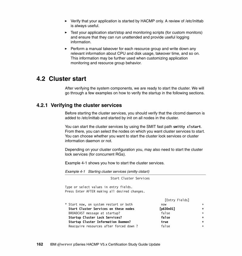
� Verify that your application is started by HACMP only. A review of /etc/inittab is always useful.
� Test your application start/stop and monitoring scripts (for custom monitors) and ensure that they can run unattended and provide useful logging information.
� Perform a manual takeover for each resource group and write down any relevant information about CPU and disk usage, takeover time, and so on. This information may be further used when customizing application monitoring and resource group behavior.
4.2 Cluster startAfter verifying the system components, we are ready to start the cluster. We will go through a few examples on how to verify the startup in the following sections.
4.2.1 Verifying the cluster servicesBefore starting the cluster services, you should verify that the clcomd daemon is added to /etc/inittab and started by init on all nodes in the cluster.
You can start the cluster services by using the SMIT fast path smitty clstart. From there, you can select the nodes on which you want cluster services to start. You can choose whether you want to start the cluster lock services or cluster information daemon or not.
Depending on your cluster configuration you, may also need to start the cluster lock services (for concurrent RGs).
Example 4-1 shows you how to start the cluster services.
Example 4-1 Starting cluster services (smitty clstart)
Start Cluster Services
Type or select values in entry fields.Press Enter AFTER making all desired changes.
[Entry Fields]* Start now, on system restart or both now + Start Cluster Services on these nodes [p630n01] + BROADCAST message at startup? false + Startup Cluster Lock Services? false + Startup Cluster Information Daemon? true + Reacquire resources after forced down ? false +
162 IBM Eserver pSeries HACMP V5.x Certification Study Guide Update

F1=Help F2=Refresh F3=Cancel F4=ListF5=Reset F6=Command F7=Edit F8=ImageF9=Shell F10=Exit Enter=Do
You can verify the status of the cluster services by using the command lssrc -g cluster. Depending on your cluster configuration, the number of services started may vary; however, the Cluster Manager daemon (clstrmgrES), Cluster SMUX Peer daemon (clsmuxpd) and Cluster Topology Services daemon (topsvcsd) should be running.
You can use commands like lssrc -g topsvcs and lssrc -g emsvcs to list the current status of the different cluster subsystems.
You can also define an alias to simplify the verification process; in our scenario, we created one called lsha by using the following command:
alias lsha='lssrc -a|egrep "svcs|ES",
We then used lsha to list the status of all the cluster related subsystems.
Example 4-2 shows you how to verify the status of cluster related services.
Example 4-2 Verifying status of cluster services
[p630n02][/]> lssrc -g clusterSubsystem Group PID Status clstrmgrES cluster 49830 active clsmuxpdES cluster 54738 active clinfoES cluster 45002 active[p630n02][/]> lssrc -g topsvcsSubsystem Group PID Status topsvcs topsvcs 53870 active[p630n02][/]> lssrc -g emsvcsSubsystem Group PID Status emsvcs emsvcs 53638 active emaixos emsvcs 53042 active[p630n02][/]> lsha clcomdES clcomdES 11404 active topsvcs topsvcs 53870 active grpsvcs grpsvcs 49074 active emsvcs emsvcs 53638 active emaixos emsvcs 53042 active clstrmgrES cluster 49830 active clsmuxpdES cluster 54738 active clinfoES cluster 45002 active
Chapter 4. Cluster verification and testing 163
grpglsm grpsvcs inoperative
4.2.2 IP verificationTo verify the IP addresses, do the following:
� Verify that all IP addresses are configured by using the command netstat -in.
� Verify the routing table using the command netstat -rn.
� If you use NFS, verify that the NFS services are started by using the command lssrc -g nfs.
4.2.3 Resource verificationTo verify the resources, do the following:
� Verify that the volume groups are varied on by using the command lsvg -o.
� Verify that the logical volumes are opened and synchronized by using the command lsvg -l your_volume_group.
� Verify that the file systems are mounted by using the command mount.
� If you have file systems to be exported, verify them by using the command showmount -e.
4.2.4 Application verificationTo verify the applications, do the following:
� Verify that your application(s) are running properly by using the command ps -ef|grep application_process.
� Verify that the clients can connect.
In the /tmp/hacmp.out log file, look for the node_up and node_up_complete events.
A sample node_up event is shown in Example 4-3 on page 165.
164 IBM Eserver pSeries HACMP V5.x Certification Study Guide Update

Example 4-3 Node_up event
:node_up[455] exit 0Jun 30 15:07:19 EVENT COMPLETED: node_up p630n01
HACMP Event SummaryEvent: node_up p630n01Start time: Wed Jun 30 15:07:07 2004
End time: Wed Jun 30 15:07:21 2004
Action: Resource: Script Name:----------------------------------------------------------------------------Acquiring resource group: rg01 process_resourcesSearch on: Wed.Jun.30.15:07:10.EDT.2004.process_resources.rg01.refAcquiring resource: All_service_addrs acquire_service_addrSearch on: Wed.Jun.30.15:07:12.EDT.2004.acquire_service_addr.All_service_addrs.rg01.refResource online: All_nonerror_service_addrs acquire_service_addrSearch on: Wed.Jun.30.15:07:16.EDT.2004.acquire_service_addr.All_nonerror_service_addrs.rg01.ref----------------------------------------------------------------------------
A sample node_up_complete event is shown in Example 4-4.
Example 4-4 Node_up_complete event
:node_up_complete[314] exit 0Jun 30 15:07:24 EVENT COMPLETED: node_up_complete p630n01
HACMP Event SummaryEvent: node_up_complete p630n01Start time: Wed Jun 30 15:07:21 2004
End time: Wed Jun 30 15:07:25 2004
Action: Resource: Script Name:----------------------------------------------------------------------------Resource group online: rg01 process_resourcesSearch on: Wed.Jun.30.15:07:22.EDT.2004.process_resources.rg01.ref----------------------------------------------------------------------------
If you encounter any problems related to cluster services starting or if you want a thorough understanding of cluster startup and the processes involved, refer to Chapter 7, “Starting and Stopping Cluster Services”, in the HACMP for AIX 5L V5.1 Adminstration and Troubleshooting Guide, SC23-4862-02.
Chapter 4. Cluster verification and testing 165
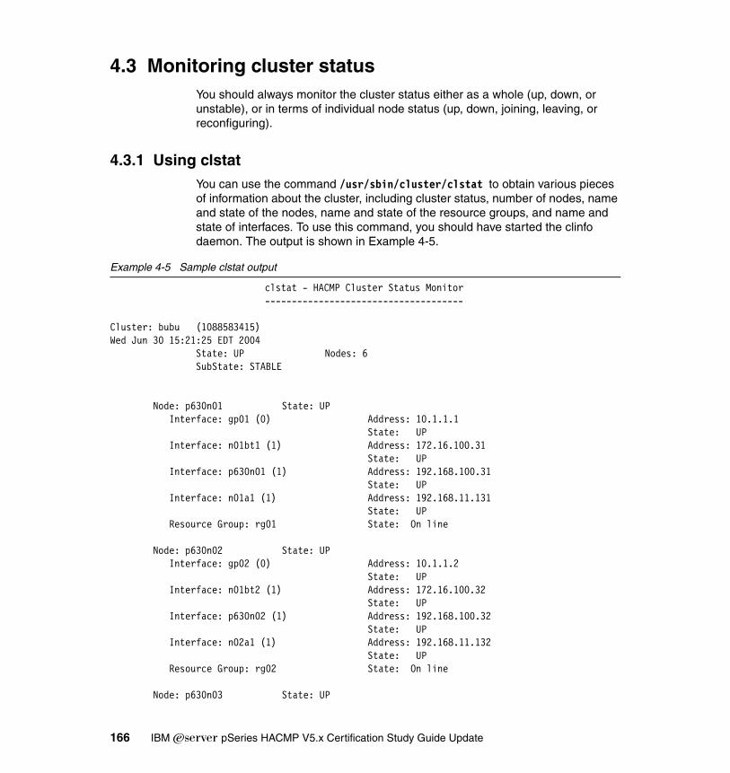
4.3 Monitoring cluster statusYou should always monitor the cluster status either as a whole (up, down, or unstable), or in terms of individual node status (up, down, joining, leaving, or reconfiguring).
4.3.1 Using clstatYou can use the command /usr/sbin/cluster/clstat to obtain various pieces of information about the cluster, including cluster status, number of nodes, name and state of the nodes, name and state of the resource groups, and name and state of interfaces. To use this command, you should have started the clinfo daemon. The output is shown in Example 4-5.
Example 4-5 Sample clstat output
clstat - HACMP Cluster Status Monitor-------------------------------------
Cluster: bubu (1088583415)Wed Jun 30 15:21:25 EDT 2004 State: UP Nodes: 6 SubState: STABLE
Node: p630n01 State: UP Interface: gp01 (0) Address: 10.1.1.1 State: UP Interface: n01bt1 (1) Address: 172.16.100.31 State: UP Interface: p630n01 (1) Address: 192.168.100.31 State: UP Interface: n01a1 (1) Address: 192.168.11.131 State: UP Resource Group: rg01 State: On line
Node: p630n02 State: UP Interface: gp02 (0) Address: 10.1.1.2 State: UP Interface: n01bt2 (1) Address: 172.16.100.32 State: UP Interface: p630n02 (1) Address: 192.168.100.32 State: UP Interface: n02a1 (1) Address: 192.168.11.132 State: UP Resource Group: rg02 State: On line
Node: p630n03 State: UP
166 IBM Eserver pSeries HACMP V5.x Certification Study Guide Update
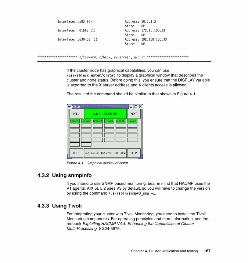
Interface: gp03 (0) Address: 10.1.1.3 State: UP Interface: n01bt3 (1) Address: 172.16.100.33 State: UP Interface: p630n03 (1) Address: 192.168.100.33 State: UP
********************** f/forward, b/back, r/refresh, q/quit ***********************
If the cluster node has graphical capabilities, you can use /usr/sbin/cluster/clstat to display a graphical window that describes the cluster and node status. Before doing this, you ensure that the DISPLAY variable is exported to the X server address and X clients access is allowed.
The result of the command should be similar to that shown in Figure 4-1.
Figure 4-1 Graphical display of clstat
4.3.2 Using snmpinfoIf you intend to use SNMP based monitoring, bear in mind that HACMP uses the V1 agents. AIX 5L 5.2 uses V3 by default, so you will have to change the version by using the command /usr/sbin/snmpv3_ssw -1.
4.3.3 Using TivoliFor integrating your cluster with Tivoli Monitoring, you need to install the Tivoli Monitoring components. For operating principles and more information, see the redbook Exploiting HACMP V4.4: Enhancing the Capabilities of Cluster Multi-Processing, SG24-5979.
Chapter 4. Cluster verification and testing 167
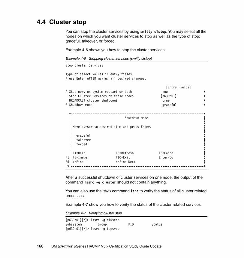
4.4 Cluster stopYou can stop the cluster services by using smitty clstop. You may select all the nodes on which you want cluster services to stop as well as the type of stop: graceful, takeover, or forced.
Example 4-6 shows you how to stop the cluster services.
Example 4-6 Stopping cluster services (smitty clstop)
Stop Cluster Services
Type or select values in entry fields.Press Enter AFTER making all desired changes.
[Entry Fields]* Stop now, on system restart or both now + Stop Cluster Services on these nodes [p630n01] + BROADCAST cluster shutdown? true +* Shutdown mode graceful +
+--------------------------------------------------------------------------+ ¦ Shutdown mode ¦ ¦ ¦ ¦ Move cursor to desired item and press Enter. ¦ ¦ ¦ ¦ graceful ¦ ¦ takeover ¦ ¦ forced ¦ ¦ ¦ ¦ F1=Help F2=Refresh F3=Cancel ¦F1¦ F8=Image F10=Exit Enter=Do ¦F5¦ /=Find n=Find Next ¦F9+--------------------------------------------------------------------------+
After a successful shutdown of cluster services on one node, the output of the command lssrc -g cluster should not contain anything.
You can also use the alias command lsha to verify the status of all cluster related processes.
Example 4-7 show you how to verify the status of the cluster related services.
Example 4-7 Verifying cluster stop
[p630n01][/]> lssrc -g clusterSubsystem Group PID Status[p630n01][/]> lssrc -g topsvcs
168 IBM Eserver pSeries HACMP V5.x Certification Study Guide Update

Subsystem Group PID Status topsvcs topsvcs inoperative[p630n01][/]> lssrc -g emsvcsSubsystem Group PID Status emsvcs emsvcs inoperative emaixos emsvcs inoperative[p630n01][/]> lsha clcomdES clcomdES 14896 active topsvcs topsvcs inoperative grpsvcs grpsvcs inoperative grpglsm grpsvcs inoperative emsvcs emsvcs inoperative emaixos emsvcs inoperative
Please notice that the clcomd daemon is running after the cluster services stop.
The type of shutdown on one node will decide the future behavior of the resource group that was acquired by that node after a successful stop of cluster services. In the log file /tmp/hacmp.out, look for the node_down and node_down_complete events.
A sample node_down event is shown in Example 4-8 on page 170.
Chapter 4. Cluster verification and testing 169

Example 4-8 Node_down event
:node_down[306] exit 0Jun 30 16:14:40 EVENT COMPLETED: node_down p630n01 graceful
HACMP Event SummaryEvent: node_down p630n01 gracefulStart time: Wed Jun 30 16:14:28 2004
End time: Wed Jun 30 16:14:43 2004
Action: Resource: Script Name:----------------------------------------------------------------------------Releasing resource group: rg01 process_resourcesSearch on: Wed.Jun.30.16:14:30.EDT.2004.process_resources.rg01.refReleasing resource: All_service_addrs release_service_addrSearch on: Wed.Jun.30.16:14:32.EDT.2004.release_service_addr.All_service_addrs.rg01.refResource offline: All_nonerror_service_addrs release_service_addrSearch on: Wed.Jun.30.16:14:35.EDT.2004.release_service_addr.All_nonerror_service_addrs.rg01.refResource group offline: rg01 process_resourcesSearch on: Wed.Jun.30.16:14:37.EDT.2004.process_resources.rg01.ref----------------------------------------------------------------------------
A sample node_down_complete event is shown in Example 4-9.
Example 4-9 Node_down_complete event
:node_down_complete[352] exit 0Jun 30 16:14:48 EVENT COMPLETED: node_down_complete p630n01 graceful
HACMP Event SummaryEvent: node_down_complete p630n01 gracefulStart time: Wed Jun 30 16:14:43 2004
End time: Wed Jun 30 16:14:48 2004
Action: Resource: Script Name:----------------------------------------------------------------------------Resource group offline: rg01 process_resourcesSearch on: Wed.Jun.30.16:14:45.EDT.2004.process_resources.rg01.ref----------------------------------------------------------------------------
Whenever possible, you should avoid using the kill -9 command to stop the Cluster Manager daemon. In such a situation, the SRC will detect that clstrmgr daemon exited abnormally and will call /usr/es/sbin/cluster/utilities/clexit.rc. This will halt your system and possibly corrupt the data that is located on shared
170 IBM Eserver pSeries HACMP V5.x Certification Study Guide Update
storage. The remaining nodes will initiate a takeover according to resource group policy.
If you encounter any problem related to cluster services stop or if you want a thorough understanding of the cluster stop process, refer to Chapter 7, “Starting and Stopping Cluster Services”, in the HACMP for AIX 5L V5.1 Adminstration and Troubleshooting Guide, SC23-4862-02.
GracefulWhen you specify this parameter, the resource groups owned by the node will be released, but will not be acquired by other nodes.
Graceful with takeoverWhen you specify this parameter, the resource groups owned by this node will be released and acquired by other nodes according to resource group type.
ForcedWhen you specify this parameter, cluster services will be stopped, but resource groups will not be released.
For a better understanding of these options, refer to Chapter 7, “Starting and Stopping Cluster Services”, in the HACMP for AIX 5L V5.1 Adminstration and Troubleshooting Guide, SC23-4862-02.
4.5 Application monitoringAfter starting the cluster services, ensure that your application is up and running, all services that application is supposed to provide are available, and clients can connect.
Verify that the application processes are up and running and all resources (volume groups, file systems, logical volumes, and IP addresses) required by the application are available.
We highly recommend you test your start and stop scripts for every application server defined. These scripts may require some modifications depending on the node on which they are running. A startup script must be carefully written to allow an application to recover from any previous abnormal termination. A stop script
Note: We do not recommend that you force down the cluster services on more than one node at a time.
Chapter 4. Cluster verification and testing 171
must allow the application to shut down correctly, keep data synchronized, and release all resources
4.5.1 Verifying application statusYou can monitor your application(s) status using either process application monitoring or custom application monitoring.
Process application monitoringThis type of monitoring uses RSCT features, works at the application process level, and it is very easy to configure. Values used for monitoring are highly dependent on the characteristics of your application. We suggest the following guidelines:
� Ensure that you defined an application server.
� Ensure that you use the output of the command ps -el to specify the process names to be monitored.
� Ensure you have specified the correct owner of the processes.
� Ensure you have specified the correct number of instances.
� You should choose a stabilization interval long enough to allow the application to recover from any previous abnormal shutdown.
� Ensure that you have set the restart count properly. You would not like to try to restart indefinitely an application that would never start on one node; instead, you should try to initiate a failover.
� Ensure that you have set the restart interval properly. If this is very small, the restart counter will be reset and a fail-over or notify action may not occur when they should.
� If you need to take any special measures in case of an application failure, include them in the script for Cleanup Method.
Custom application monitoringYou will have to write your own scripts that will monitor all parameters related to your application. Use this method whenever you cannot use process application monitoring. Ensure your script returns exit code 0 if the application is working properly.
172 IBM Eserver pSeries HACMP V5.x Certification Study Guide Update

4.5.2 Verifying resource group statusWhen you monitor the cluster, you might be interested to see the status of the resource groups and topology. A resource group can be found in one of the following states: online, offline, acquiring, releasing, error, temporary error, or unknown.
You can use the commands /usr/es/sbin/cluster/utilities/clfindres or clRGinfo to find out the status of resource groups. The results will be identical because /usr/es/sbin/cluster/utilities/clfindres calls clRGinfo.
The most often used flags of this command are:
-t Use this flag if you want to display the settling time and delayed fallback timer settings for a custom resource group.
-p Use this flag if you want to display priority override locations for a resource group.
For further details about these flags, refer to Chapter 7, “Starting and Stopping Cluster Services”, in the HACMP for AIX 5L V5.1 Adminstration and Troubleshooting Guide, SC23-4862-02.
The output of this command with the -p flag is shown in Example 4-10.
Example 4-10 Sample clRGinfo -p output
[p630n01][/]> /usr/es/sbin/cluster/utilities/clRGinfo -p-----------------------------------------------------------------------------Group Name Type State Location Priority Override-----------------------------------------------------------------------------rg01 cascading ONLINE p630n01 OFFLINE p630n02 OFFLINE p630n03 OFFLINE p630n04 OFFLINE p630n05 OFFLINE p630n06
rg02 cascading ONLINE p630n02 OFFLINE p630n03 OFFLINE p630n04 OFFLINE p630n05 OFFLINE p630n06 OFFLINE p630n01
rg03 cascading OFFLINE p630n03 p630n04 (PERSISTENT) ONLINE p630n04 p630n04 (PERSISTENT) OFFLINE p630n05 p630n04 (PERSISTENT) OFFLINE p630n06 p630n04 (PERSISTENT)
Chapter 4. Cluster verification and testing 173

OFFLINE p630n01 p630n04 (PERSISTENT) OFFLINE p630n02 p630n04 (PERSISTENT)
rg04 cascading ONLINE p630n04 OFFLINE p630n05 OFFLINE p630n06 OFFLINE p630n01 OFFLINE p630n02 OFFLINE p630n03
rg05 cascading OFFLINE p630n05 OFFLINE (PERSISTENT) OFFLINE p630n06 OFFLINE (PERSISTENT) OFFLINE p630n01 OFFLINE (PERSISTENT) OFFLINE p630n02 OFFLINE (PERSISTENT) OFFLINE p630n03 OFFLINE (PERSISTENT) OFFLINE p630n04 OFFLINE (PERSISTENT)
rg06 cascading ONLINE p630n06 OFFLINE p630n01 OFFLINE p630n02
You can always use the command /usr/es/sbin/cluster/utilities/cltopinfo to review cluster topology, as shown in Example 4-11.
Example 4-11 Cltopinfo sample output
Cluster Description of Cluster: bubuCluster Security Level: StandardThere are 6 node(s) and 7 network(s) definedNODE p630n01: Network net_diskhb_01 Network net_diskhb_02 p630n01_hdisk30_01 /dev/hdisk30 Network net_ether_01 gp01 10.1.1.1 Network net_ether_02 n02a1 192.168.11.132 n04a1 192.168.11.134 n03a1 192.168.11.133 n06a1 192.168.11.136 n05a1 192.168.11.135 n01a1 192.168.11.131 p630n01 192.168.100.31 n01bt1 172.16.100.31 Network net_rs232_01 Network net_rs232_02 Network net_rs232_03NODE p630n02:
174 IBM Eserver pSeries HACMP V5.x Certification Study Guide Update
Network net_diskhb_01
There are different flags used for formatting the output. Please see the manual page for this command.
For a detailed description of available tools for cluster status monitoring, refer to Chapter 8, “Monitoring an HACMP Cluster“, in the HACMP for AIX 5L V5.1 Adminstration and Troubleshooting Guide, SC23-4862-02.
4.5.3 Verifying NFS functionality
There are a few restrictions that you should be aware of in the way that NFS is implemented when using HACMP. NFS behavior is different if you use IPAT via IP aliases or Replacement. Please take a note of which type of resource group your file systems belong to (cascading, rotating, or custom), and the number of available service, boot interfaces, and routes in the routing table.
You can chose between two different types of NFS mounts: hard and soft.
� If you try to soft mount a file system and exporting NFS server is unavailable, you will receive an error.
� A client trying to hard mount a file system when exporting NFS server is unavailable will try until the server becomes available, which may not be suitable for your application.
It is a good common practice to ensure that the host name of each node matches the service label, because some applications use the host name.
In our example of testing NFS, we will use a cluster containing two nodes, two cascading resource groups, and two file systems exported over the service address.
We tested NFS functionality using the following steps:
1. Defined two volume groups, vg01 and vg02. Ensure that the major number for each volume group is identical on both nodes.
Note: Before you start using NFS, you should be aware that the recovery feature and locking restore functionalities (in case of a NFS server failure) are available only for a two node cluster.
Note: Hard mount is the default choice.
Chapter 4. Cluster verification and testing 175

2. Defined, within each volume group, a logical volume and a file system that will be exported, and named them /ap1_fs and /app2_fs. Ensured that logical volumes names and jfslog names are consistent on both nodes.
3. You can perform previous tasks using C-SPOC and should not be worried about volume group major numbers, logical volume names, or jfslog names being unique around the cluster.
4. Defined two cascading resource groups named rg01 and rg02.
5. For rg01, defined participating nodes as node 1 and node 2.
6. For rg02, defined participating nodes as node 2 and node 1.
7. Created two directories that will be used for mounting file systems: /mount_point1 and /mount_point2.
8. Run smitty hacmp and go to the Change/Show All Resources and Attributes for a Cascading Resource Group panel.
9. For rg01m, specify:
� /app1_fs in the Filesystems field� true in the Filesystem mounted before IP Configured field� /app1_fs in the Filesystems/Directories to Export field� /mount_point1;/app1_fs in the Filesystems/Directories to NFS mount field � service network in the Network For NFS Mount field
10.For rg02, specify:
� /app2_fs in the Filesystems field� true in the Filesystem mounted before IP Configured field� /app2_fs in the Filesystems/Directories to Export field� /mount_point2;/app2_fs in the Filesystems/Directories to NFS mount field� service network in the Network For NFS Mount field
11.If you plan to use specific options for NFS exports, you must edit the file /usr/es/sbin/cluster/etc/exports. The file has the same format as the AIX /etc/exports file.
12.Synchronize cluster resources.
13.Start cluster services on both nodes.
14.Verify that cluster and NFS services started successfully by running the commands lssrc -g cluster and lssrc -g nfs, respectively.
15.Verify that node 1 has varied on vg01. /filesystem1 should be locally mounted and /filesystem2 should be NFS mounted. Verify that node 1 has NFS exported /filesystem1 using the command showmount -e.
16.Verify that node 2 has varied on vg02. /filesystem2 should be locally mounted and /filesystem1 should be NFS mounted. Verify that node 2 has NFS exported /filesystem2 using the command showmount -e.
176 IBM Eserver pSeries HACMP V5.x Certification Study Guide Update
17.Stop cluster services on node 1 using the takeover option.
18.Verify that node 2 has varied on vg01. /filesystem1 and /filesystem2 should be both locally and NFS mounted. They should be NFS exported as well.
19.Restart the cluster services on node 1. /filesystem1 should be again mounted both locally and by NFS. node 2 should be able to NFS mount /filesystem1.
4.6 Cluster behavior on node failoverSimulate a node crash either by powering off or running the commands cp /dev/zero /dev/kmem or halt -q on the node you intend to fail.
Verify that resource group(s) that were acquired by the failing node will migrate the way they should and the cluster still provides services to its clients.
4.7 Testing IP networksBefore testing your cluster behavior on a IP failure, you have to ensure that the network environment in which the cluster will run is properly set:
� If your network uses VLANs, ensure that all physical interfaces are connected to the same VLAN.
� If your cluster uses MAC address takeover, ensure that your switch ports are not bound to a specific MAC address.
� Set the interface speed to a specific value and use duplex communication if possible. Ensure that the speed to which the interface is set matches the speed of the switch interface. Verify that you will have the same setting in case of failover.
� Verify ARP related settings of your network environment. A router having Proxy ARP enabled may interfere with cluster takeover. Verify that your network supports Gratuitous ARP and UDP broadcast.
� You should not avoid using active network devices (routers, layer 3 switches, firewalls, and so on) to connect cluster nodes, since these types of devices may block UDP broadcasts and other types of messages that are used for communication between cluster nodes.
� Verify that failure of any network interface would not lead to cluster partitioning.
Chapter 4. Cluster verification and testing 177

4.7.1 Communication adapter failureWe have added a few steps to simulate a network interface failure on a node containing an undetermined number of interfaces:
1. Unplug the cable from the adapter.
2. If the adapter was configured with a service IP address, then:
– Verify in /tmp/hacmp.out that event “swap_adapter” has occurred.
– Verify that the service IP address has been moved using the command netstat -in.
• If you were using IPAT via aliasing, the service IP address should have been aliased on one of the available boot interfaces.
• If you were using IPAT via replacement, the service IP address should have been moved on one of the available standby interfaces
– Verify that persistent address (if any) has been moved to another available interface.
– Plug the cable into the network adapter.
• If you were using IPAT via aliasing, the boot IP address should become available.
• If you were using IPAT via replacement, the standby IP address should be available.
3. If the adapter was not configured with a service IP address, then its IP address will be removed from the cluster. Any persistent address configured on this interface should be aliased on another available interface.
4. Unplug and plug the cables for all interfaces one at a time.
4.7.2 Network failureTo avoid a single point of failure, you should use more than one switch to connect the cluster to the external environment and ensure that clients can connect to the cluster using any of them.
You can use the following steps to test that your cluster is resilient to switch failure by powering off the switch and verifying that the cluster IP service addresses have been migrated (either aliased or by replacement) to interfaces connected to remaining switch by using the command netstat -in.
178 IBM Eserver pSeries HACMP V5.x Certification Study Guide Update
4.7.3 Verifying persistent IP labels1. Ensure that the persistent node IP label is not defined in any resource group.
2. Fail the network interface that supports the IP service label. The persistent node IP label should be moved to the same boot interface on which the service interface is migrated.
3. Fail other network interfaces one at a time and wait for the cluster to stabilize. The persistent IP label should migrate to the next available boot interface.
4. When you failed all network interfaces, the IP persistent label should be unavailable.
5. Reenable all network interfaces.
6. Stop the cluster services. The IP persistent label should still be available.
7. Restart the node. The IP persistent label should still be available.
4.8 Testing non-IP networksThe purpose of this section is to describe some methods used to test non-IP connections between cluster nodes.
4.8.1 Serial networksYou can implement a RS232 heartbeat network between any two nodes of the cluster.
To test a serial connection between two nodes, do the following steps:
1. Run the command lsdev -Cc tty on both nodes to verify that the tty device you intend to use is available. Let us suppose that you are using tty1 at both ends of the serial connection.
2. Ensure that the baud rate is set to 38400, parity to none, bits per character to 8, number of stop bits to 1, and enable login to disable.
3. Ensure that you use a null-modem cable.
4. Ensure that the cluster services are not running.
5. On node 1, run the command cat < /dev/tty1.
6. On node 2, run cat /etc/hosts > /dev/tty1. You should be able to see /etc/hosts on your console on node 1.
7. Repeat the test in the opposite direction.
Chapter 4. Cluster verification and testing 179

4.8.2 SCSI networksYou can implement a SCSI heartbeat network between any two nodes of the cluster. To test a SCSI heartbeat network, we suggest the following steps:
1. Verify that the fileset devices.scsi.tm.rte is installed on both nodes.
2. Ensure that both nodes are properly connected to SCSI storage.
3. Ensure that the SCSI IDs for all devices connected to a shared bus are unique. Do not use number 7, since this value is assigned by AIX each time it configures a newly added adapter or when the system is booted in service mode.
4. Enable target mode for every SCSI adapter. Verify that tmscsi device is in the available state.
5. Ensure that cluster services are not running.
6. On node 1, run the command cat < /dev/tmscsi#.tm, where # is the ID of the target device.
7. On node 2, run the command cat /etc/hosts > /dev/tmscsi#.in, where # is the ID of the initiator device. You should be able to see the /etc/hosts file on your console on node 1.
8. Repeat the test in the opposite direction.
4.8.3 SSA networksYou can implement a SSA heartbeat network between any two nodes of the cluster. To test a SSA heartbeat network, we suggest the following steps:
1. Verify that the fileset devices.ssa.tm.rte is installed on both nodes.
2. Ensure that you set the SSA router ID properly by using the command chdev -l ssar -a node_number=x, where x is a unique non zero number. You must use the value of the node ID of cluster nodes.
3. Ensure that both nodes are properly connected to SSA storage.
4. Ensure that cluster services are not running.
5. On node 1, run the command cat < /dev/tmssa#.tm.
6. On node 2, run the command cat /etc/hosts > /dev/tmssa#.in. You should be able to see the /etc/hosts file on your console on node 1.
7. Repeat the test in the opposite direction.
180 IBM Eserver pSeries HACMP V5.x Certification Study Guide Update

4.8.4 Heartbeat over disk networksTo test a disk heartbeat network, do the following steps:
1. Ensure that the PVID of the disk is identical on both nodes of the connection.
2. Ensure that the disk is defined as a member of a enhanced concurrent volume group on both cluster nodes.
3. Verify that you have installed the correct version of the bos.clvm.enh and RSCT filesets.
4. Run the command /usr/es/sbin/cluster/utilities/clrsctinfo -cp cllsif|grep diskhb and verify that the nodes’ synchronization was successful. We used hdisk30 for the definition of the disk heartbeat network between cluster nodes one and two, as you can see in Example 4-12.
Example 4-12 Clrsctinfo output sample
[p630n02][/]> /usr/es/sbin/cluster/utilities/clrsctinfo -cp cllsif|grep diskhbp630n01_hdisk30_01:service:net_diskhb_02:diskhb:serial:p630n01:/dev/rhdisk30::hdisk30::p630n02_hdisk30_01:service:net_diskhb_02:diskhb:serial:p630n02:/dev/rhdisk30::hdisk30::
5. On node 1, run the command /usr/sbin/rsct/bin/dhb_read -p /dev/hdisk30 -r. Your result should be similar to the one shown in Example 4-13.
Example 4-13 Disk heartbeat receive
[p630n02][/]> /usr/sbin/rsct/bin/dhb_read -p /dev/hdisk30 -rReceive Mode:Waiting for response . . .Link operating normally
6. On node 2, run the command /usr/sbin/rsct/bin/dhb_read -p /dev/hdisk30 -t.
7. Your result should be similar to that in Example 4-14.
Example 4-14 Disk heartbeat transmit
[p630n01][/]> /usr/sbin/rsct/bin/dhb_read -p /dev/hdisk30 -tTransmit Mode:Detected remote utility in receive mode. Waiting for response . . .Link operating normally
8. Repeat the test in the opposite direction.
9. Go to the directory /var/ha/log.
10.If your cluster is named certification and you used disk 27, run the command tail -f nim.topsvcs.rhdisk27.certification.
Chapter 4. Cluster verification and testing 181
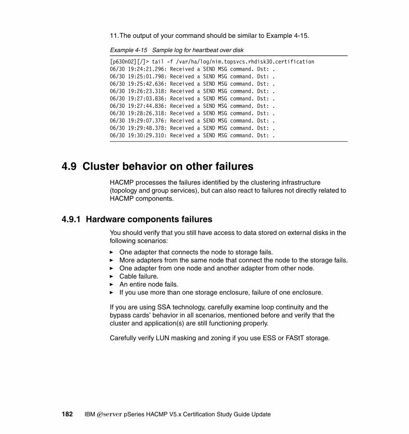
11.The output of your command should be similar to Example 4-15.
Example 4-15 Sample log for heartbeat over disk
[p630n02][/]> tail -f /var/ha/log/nim.topsvcs.rhdisk30.certification06/30 19:24:21.296: Received a SEND MSG command. Dst: .06/30 19:25:01.798: Received a SEND MSG command. Dst: .06/30 19:25:42.636: Received a SEND MSG command. Dst: .06/30 19:26:23.318: Received a SEND MSG command. Dst: .06/30 19:27:03.836: Received a SEND MSG command. Dst: .06/30 19:27:44.836: Received a SEND MSG command. Dst: .06/30 19:28:26.318: Received a SEND MSG command. Dst: .06/30 19:29:07.376: Received a SEND MSG command. Dst: .06/30 19:29:48.378: Received a SEND MSG command. Dst: .06/30 19:30:29.310: Received a SEND MSG command. Dst: .
4.9 Cluster behavior on other failuresHACMP processes the failures identified by the clustering infrastructure (topology and group services), but can also react to failures not directly related to HACMP components.
4.9.1 Hardware components failuresYou should verify that you still have access to data stored on external disks in the following scenarios:
� One adapter that connects the node to storage fails.� More adapters from the same node that connect the node to the storage fails.� One adapter from one node and another adapter from other node.� Cable failure.� An entire node fails.� If you use more than one storage enclosure, failure of one enclosure.
If you are using SSA technology, carefully examine loop continuity and the bypass cards’ behavior in all scenarios, mentioned before and verify that the cluster and application(s) are still functioning properly.
Carefully verify LUN masking and zoning if you use ESS or FAStT storage.
182 IBM Eserver pSeries HACMP V5.x Certification Study Guide Update
4.9.2 Rootvg mirror and internal disk failureA mirrored rootvg that uses at least two disks can help you avoid a rootvg crash.
To test this scenario, we suggest to follow the following steps:
1. Verify that rootvg contains at least two internal disks using the command lsvg -p rootvg.
2. Verify that the logical volumes are synchronized and that there are not any stale partitions using the command lsvg -l rootvg.
3. Verify that all disks are included in the bootlist using the command bootlist -m normal -o.
4. Disconnect the power supply of one disk or, in the case of hot-plug disks, remove the disk from its enclosure.
5. Verify that the system is functioning normally.
6. Reboot the system.
7. Attach the disconnected disk.
8. Synchronize rootvg.
4.9.3 AIX and LVM level errorsHACMP can only detect three types of failures:
� Network interface card failure� Node failure� Network failure
Cluster behavior is influenced by other events, like a loss of quorum for a volume group or application failure, but it does not react to these events directly.
4.9.4 Forced varyon of VGsTo fully understand this feature, a good understanding of AIX LVM is mandatory.
Quorum enabledWhen quorum is enabled, more than half of the copies of VGDA and VGSA must be accessible to read and identical in content for the varyonvg command to succeed. If a write operation to a disk fails, VGSAs on other physical volumes are updated to indicate that failure. As long as more than half of all VGDAs and VGSAs can be written, quorum will be maintained and the volume group will remain varied on. However, data on missing physical volumes is not available unless a mirror copy of that data is located on another available physical volume. It is still possible to have all copies of data lost and the volume group still
Chapter 4. Cluster verification and testing 183

accessible and varied on because a majority of VGDA and VGSA copies from other disks are still available.
We do not recommend the use of quorum in a HACMP configuration.
Quorum disabledWhen quorum is disabled, all copies of VGDA and VGSA must be accessible to read and identical in content for the varyonvg command to succeed. If a write operation to a disk fails, VGSAs on other physical volumes are updated to indicate that failure. As long as at least one copy of VGDA and VGSA can be written, the volume group will remain varied on, but data integrity is no longer guaranteed.
Forced varyonThis new feature of HACMP V5.1 allows you to force a varyonvg if normal varyonvg operation fails.
You cant test the forced varyon feature by doing the following steps:
1. Define one volume group containing at least two physical volumes. A volume group should include at least one logical volume with at least two copies of data on different disks. A volume group should be accessible from at least two nodes of the cluster. You can easily perform this task using C-SPOC.
2. Include the volume group previously defined in one resource group. The participating nodes for this resource group should include at least two nodes, for example, suppose we have defined a cascading resource group with participating nodes node1 and node 2.
3. For this resource, set the parameter Use forced varyon of volume groups, if necessary, to true in the Extended Resource Group Configuration panel.
4. Synchronize the cluster resources.
5. Start the cluster services on node 1 and node 2.
6. Verify that the volume group is varied on node 1.
7. Verify that the logical volumes are opened and the file systems are mounted.
8. Create a test file on one of the file systems.
9. Fail enough disks of the volume group so that only one copy of VGDA and VGSA will be available.
10.In our test, we defined a two disk volume group and erased the PVID from the disk containing two VGDAs using following command dd if=/dev/zero of=/dev/hdisk5 bs=128.
This operation will render the disk unusable for varyon process. The result of previous command can be shown in Example 4-16 on page 185.
184 IBM Eserver pSeries HACMP V5.x Certification Study Guide Update

Example 4-16 PVID erased from disk
[p630n02][/]> dd if=/dev/zero of=/dev/hdisk36 bs=128[p630n02][/]> lquerypv -h /dev/hdisk3600000000 00000000 00000000 00000000 00000000 |................|00000010 00000000 00000000 00000000 00000000 |................|00000020 00000000 00000000 00000000 00000000 |................|00000030 00000000 00000000 00000000 00000000 |................|00000040 00000000 00000000 00000000 00000000 |................|00000050 00000000 00000000 00000000 00000000 |................|00000060 00000000 00000000 00000000 00000000 |................|00000070 00000000 00000000 00000000 00000000 |................|00000080 00000000 00000000 00000000 00000000 |................|00000090 00000000 00000000 00000000 00000000 |................|000000A0 00000000 00000000 00000000 00000000 |................|000000B0 00000000 00000000 00000000 00000000 |................|000000C0 00000000 00000000 00000000 00000000 |................|000000D0 00000000 00000000 00000000 00000000 |................|000000E0 00000000 00000000 00000000 00000000 |................|000000F0 00000000 00000000 00000000 00000000 |................|
11.On node 1, stop the cluster services using the takeover option.
12.Verify that the volume group is varied on, on node 2.
13.Verify that the file systems are mounted and you can access test file.
4.10 RSCT verificationYou can test to see if RSCT is functioning properly using the following command:
lssrc -ls topsvcs
The output of this command is shown in Example 4-17.
Example 4-17 Sample output of lssrc -ls topsvcs
Subsystem Group PID Status topsvcs topsvcs 34684 activeNetwork Name Indx Defd Mbrs St Adapter ID Group IDnet_ether_01_0 [ 0] 6 6 S 10.1.1.5 10.1.1.6net_ether_01_0 [ 0] en1 0x40e0a036 0x40e33664HB Interval = 1.000 secs. Sensitivity = 5 missed beatsMissed HBs: Total: 0 Current group: 0Packets sent : 131105 ICMP 0 Errors: 0 No mbuf: 0Packets received: 146119 ICMP 0 Dropped: 0NIM's PID: 49964net_ether_02_0 [ 1] 6 1 S 192.168.100.35 192.168.100.35net_ether_02_0 [ 1] en0 0x80e0a034 0x40e3362e
Chapter 4. Cluster verification and testing 185

HB Interval = 1.000 secs. Sensitivity = 5 missed beatsMissed HBs: Total: 0 Current group: 0Packets sent : 53244 ICMP 0 Errors: 0 No mbuf: 0Packets received: 26584 ICMP 0 Dropped: 0NIM's PID: 24444net_ether_02_1 [ 2] 6 2 S 172.16.100.35 172.16.100.35net_ether_02_1 [ 2] en2 0x40e0a035 0x80e336b3HB Interval = 1.000 secs. Sensitivity = 5 missed beatsMissed HBs: Total: 1 Current group: 0Packets sent : 119853 ICMP 0 Errors: 0 No mbuf: 0Packets received: 119593 ICMP 0 Dropped: 0NIM's PID: 35252 2 locally connected Clients with PIDs:haemd( 32142) hagsd( 42784) Dead Man Switch Enabled: reset interval = 1 seconds trip interval = 20 seconds Configuration Instance = 166 Default: HB Interval = 1 secs. Sensitivity = 4 missed beats Daemon employs no security Segments pinned: Text Data. Text segment size: 743 KB. Static data segment size: 644 KB. Dynamic data segment size: 3467. Number of outstanding malloc: 445 User time 35 sec. System time 36 sec. Number of page faults: 0. Process swapped out 0 times. Number of nodes up: 6. Number of nodes down: 0.
To check the RSCT group services, refer to Example 4-18.
Example 4-18 Sample output of lssrc -ls grpsvcs
Subsystem Group PID Status grpsvcs grpsvcs 42784 active2 locally-connected clients. Their PIDs:32142(haemd) 21124(clstrmgr)HA Group Services domain information:Domain established by node 2Number of groups known locally: 3 Number of Number of localGroup name providers providers/subscribersha_em_peers 6 1 0CLRESMGRD_1088583415 6 1 0CLSTRMGR_1088583415 6 1 0
You can use the log file cllsif.log from /var/ha/run/topsvcs.your_cluster_name to closely monitor heartbeat over all the defined networks. You can see a sample of this file in Example 4-19 on page 187.
186 IBM Eserver pSeries HACMP V5.x Certification Study Guide Update

Example 4-19 Sample cllsinfo.log
p630n01_hdisk30_01:service:net_diskhb_02:diskhb:serial:p630n01:/dev/rhdisk30::hdisk30::gp01:boot:net_ether_01:ether:public:p630n01:10.1.1.1::en1::255.255.255.0p630n01:boot:net_ether_02:ether:public:p630n01:192.168.100.31::en0::255.255.255.0n01bt1:boot:net_ether_02:ether:public:p630n01:172.16.100.31::en2::255.255.255.0n06a1:service:net_ether_02:ether:public:p630n01:192.168.11.136::::255.255.255.0n05a1:service:net_ether_02:ether:public:p630n01:192.168.11.135::::255.255.255.0n02a1:service:net_ether_02:ether:public:p630n01:192.168.11.132::::255.255.255.0n04a1:service:net_ether_02:ether:public:p630n01:192.168.11.134::::255.255.255.0n03a1:service:net_ether_02:ether:public:p630n01:192.168.11.133::::255.255.255.0n01a1:service:net_ether_02:ether:public:p630n01:192.168.11.131::::255.255.255.0p630n02_hdisk30_01:service:net_diskhb_02:diskhb:serial:p630n02:/dev/rhdisk30::hdisk30::gp02:boot:net_ether_01:ether:public:p630n02:10.1.1.2::en1::255.255.255.0n01bt2:boot:net_ether_02:ether:public:p630n02:172.16.100.32::en2::255.255.255.0p630n02:boot:net_ether_02:ether:public:p630n02:192.168.100.32::en0::255.255.255.0n06a1:service:net_ether_02:ether:public:p630n02:192.168.11.136::::255.255.255.0n05a1:service:net_ether_02:ether:public:p630n02:192.168.11.135::::255.255.255.0n02a1:service:net_ether_02:ether:public:p630n02:192.168.11.132::::255.255.255.0n04a1:service:net_ether_02:ether:public:p630n02:192.168.11.134::::255.255.255.0n03a1:service:net_ether_02:ether:public:p630n02:192.168.11.133::::255.255.255.0n01a1:service:net_ether_02:ether:public:p630n02:192.168.11.131::::255.255.255.0gp03:boot:net_ether_01:ether:public:p630n03:10.1.1.3::en1::255.255.255.0p630n03:boot:net_ether_02:ether:public:p630n03:192.168.100.33::en0::255.255.255.0n01bt3:boot:net_ether_02:ether:public:p630n03:172.16.100.33::en2::255.255.255.0n06a1:service:net_ether_02:ether:public:p630n03:192.168.11.136::::255.255.255.0n05a1:service:net_ether_02:ether:public:p630n03:192.168.11.135::::255.255.255.0n02a1:service:net_ether_02:ether:public:p630n03:192.168.11.132::::255.255.255.0n04a1:service:net_ether_02:ether:public:p630n03:192.168.11.134::::255.255.255.0n03a1:service:net_ether_02:ether:public:p630n03:192.168.11.133::::255.255.255.0n01a1:service:net_ether_02:ether:public:p630n03:192.168.11.131::::255.255.255.0p630n03_tty0_01:service:net_rs232_02:rs232:serial:p630n03:/dev/tty0::tty0::gp04:boot:net_ether_01:ether:public:p630n04:10.1.1.4::en1::255.255.255.0n01bt4:boot:net_ether_02:ether:public:p630n04:172.16.100.34::en2::255.255.255.0p630n04:boot:net_ether_02:ether:public:p630n04:192.168.100.34::en0::255.255.255.0n06a1:service:net_ether_02:ether:public:p630n04:192.168.11.136::::255.255.255.0n05a1:service:net_ether_02:ether:public:p630n04:192.168.11.135::::255.255.255.0n02a1:service:net_ether_02:ether:public:p630n04:192.168.11.132::::255.255.255.0n04a1:service:net_ether_02:ether:public:p630n04:192.168.11.134::::255.255.255.0n03a1:service:net_ether_02:ether:public:p630n04:192.168.11.133::::255.255.255.0n01a1:service:net_ether_02:ether:public:p630n04:192.168.11.131::::255.255.255.0p630n04_tty0_01:service:net_rs232_02:rs232:serial:p630n04:/dev/tty0::tty0::gp05:boot:net_ether_01:ether:public:p630n05:10.1.1.5::en1::255.255.255.0
The file machines.your_cluster_id.lst from the directory /var/ha/run/topsvcs.your_cluster_name contains vital topology information about your cluster.
Chapter 4. Cluster verification and testing 187

A sample of this file is shown Example 4-20.
Example 4-20 Sample machines.cluster_id.lst
*InstanceNumber=166*configId=1407358441*!TS_realm=HACMP*!TS_EnableIPAT*!TS_PinText*!TS_PinData*!TS_HACMP_version=6TS_Frequency=1TS_Sensitivity=4TS_FixedPriority=38TS_LogLength=5000Network Name net_ether_01_0Network Type ether*!NIM_pathname=/usr/sbin/rsct/bin/hats_nim*!NIM_Src_Routing=1*!TS_Frequency=1*!TS_Sensitivity=5**Node Type Address 1 en1 10.1.1.1 2 en1 10.1.1.2 3 en1 10.1.1.3 4 en1 10.1.1.4 5 en1 10.1.1.5 6 en1 10.1.1.6Network Name net_ether_02_0Network Type ether*!NIM_pathname=/usr/sbin/rsct/bin/hats_nim*!NIM_Src_Routing=1*!TS_Frequency=1*!TS_Sensitivity=5**Node Type Address 1 en0 192.168.100.31 2 en0 192.168.100.32 3 en0 192.168.100.33 4 en0 192.168.100.34 5 en0 192.168.100.35 6 en0 192.168.100.36Network Name net_ether_02_1Network Type ether*!NIM_pathname=/usr/sbin/rsct/bin/hats_nim*!NIM_Src_Routing=1*!TS_Frequency=1*!TS_Sensitivity=5
188 IBM Eserver pSeries HACMP V5.x Certification Study Guide Update
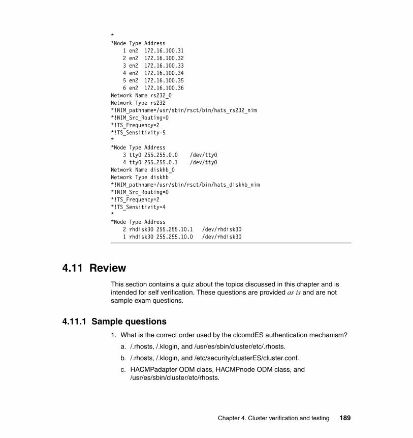
**Node Type Address 1 en2 172.16.100.31 2 en2 172.16.100.32 3 en2 172.16.100.33 4 en2 172.16.100.34 5 en2 172.16.100.35 6 en2 172.16.100.36Network Name rs232_0Network Type rs232*!NIM_pathname=/usr/sbin/rsct/bin/hats_rs232_nim*!NIM_Src_Routing=0*!TS_Frequency=2*!TS_Sensitivity=5**Node Type Address 3 tty0 255.255.0.0 /dev/tty0 4 tty0 255.255.0.1 /dev/tty0Network Name diskhb_0Network Type diskhb*!NIM_pathname=/usr/sbin/rsct/bin/hats_diskhb_nim*!NIM_Src_Routing=0*!TS_Frequency=2*!TS_Sensitivity=4**Node Type Address 2 rhdisk30 255.255.10.1 /dev/rhdisk30 1 rhdisk30 255.255.10.0 /dev/rhdisk30
4.11 ReviewThis section contains a quiz about the topics discussed in this chapter and is intended for self verification. These questions are provided as is and are not sample exam questions.
4.11.1 Sample questions1. What is the correct order used by the clcomdES authentication mechanism?
a. /.rhosts, /.klogin, and /usr/es/sbin/cluster/etc/.rhosts.
b. /.rhosts, /.klogin, and /etc/security/clusterES/cluster.conf.
c. HACMPadapter ODM class, HACMPnode ODM class, and /usr/es/sbin/cluster/etc/rhosts.
Chapter 4. Cluster verification and testing 189

d. HACMPadapter ODM class, HACMPcluster ODM class, and HACMPnode ODM class.
2. What is the authorization method for HACMP commands provided by clcomdES?
a. Least privilege principle.
b. Kerberos authorization.
c. Access control list (ACLs).
d. Authentication is not needed by clcomdES.
3. Which command is used to check the resource group status?
a. /usr/es/sbin/cluster/utilities/clfindres.
b. /usr/es/sbin/cluster/utilities/clRGinfo.
c. /usr/es/sbin/cluster/utilities/clRGinfo -t.
d. /usr/es/sbin/cluster/utilities/clRGinfo -p.
4. Which command is used to check if the diskhb network is up and running?
a. netstat -in.
b. lsvg -o | grep diskhb.
c. /usr/es/sbin/cluster/utilities/clrsctinfo -cp cllsif |grep diskhb.
d. lssrc -ls hdiskhb.
190 IBM Eserver pSeries HACMP V5.x Certification Study Guide Update

5. Which command should be used to test a disk heartbeat network?
a. cat /dev/zero > /dev/kmem.
b. /usr/sbin/rsct/bin/dhb_read.
c. ping /dev/rhdisk*.
d. dd if=/dev/zero of=/dev/diskX count=5.
Chapter 4. Cluster verification and testing 191

192 IBM Eserver pSeries HACMP V5.x Certification Study Guide Update
Chapter 5. Post implementation and administration
This chapter provides information about post installation and administrative tasks that should be performed during normal cluster operation.
Maintaining a cluster configuration and applying changes to a running cluster requires rigorous procedures and change management; otherwise, the cluster may remain unbalanced, and may not react as designed in a failure (take-over) situation.
System administrators and application administrators must work together to maintain a working cluster that delivers expected results each time.
5
© Copyright IBM Corp. 2004, 2006. All rights reserved. 193
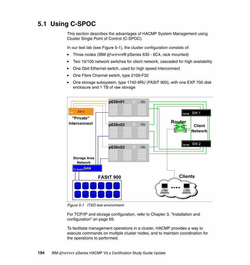
5.1 Using C-SPOCThis section describes the advantages of HACMP System Management using Cluster Single Point of Control (C-SPOC).
In our test lab (see Figure 5-1), the cluster configuration consists of:
� Three nodes (IBM ^® pSeries 630 - 6C4, rack mounted)
� Two 10/100 network switches for client network, cascaded for high availability
� One Gbit Ethernet switch, used for high speed interconnect
� One Fibre Channel switch, type 2109-F32
� One storage subsystem, type 1742-9RU (FAStT 900), with one EXP 700 disk enclosure and 1 TB of raw storage
Figure 5-1 ITSO test environment
For TCP/IP and storage configuration, refer to Chapter 3, “Installation and configuration” on page 69.
To facilitate management operations in a cluster, HACMP provides a way to execute commands on multiple cluster nodes, and to maintain coordination for the operations to performed.
SW 1
SW 210/100
10/100SW 3Gbit
SANFC Switch
FAStT 900 Clients
Router"Private"
Interconnect
p630n01
p630n02
p630n03
Storage AreaNetwork
ClientNetwork
194 IBM Eserver pSeries HACMP V5.x Certification Study Guide Update

Some of the cluster maintenance operations may affect the HACMP configuration (topology and resources), but through the HACMP System Management tool (C-SPOC), these tasks (such as adding or removing resources, users, and changing topology elements) can be performed without stopping mission-critical jobs.
C-SPOC considerationsThe C-SPOC tool simplifies maintenance of shared LVM components in clusters of up to 32 nodes. C-SPOC commands provide comparable functions in a cluster environment to the standard AIX commands that work on a single node. By automating repetitive tasks, C-SPOC eliminates a potential source of errors, and speeds up the process.
Without C-SPOC functionality, the system administrator would spend time executing administrative tasks individually on each cluster node. For example, to add an user to some of (or all) the nodes in the cluster, you must perform this task on each cluster node.
Using the C-SPOC utility, a command executed on one node (the one that initiates the changes) is also executed on other cluster nodes. C-SPOC minimizes administrative overhead and reduces the possibility of inconsistent node states. For example, when using C-SPOC to add an user, the user is added to all specified cluster nodes.
C-SPOC provides this functionality through its own set of cluster administration commands, accessible through SMIT menus and panels, and also via the command line. We do not recommend using the command line interface, unless you are sure of what you are trying to achieve. To use C-SPOC, select the Cluster System Management option from the HACMP SMIT menu.
Attention: C-SPOC uses the new cluster communication daemon (clcomdES) to execute commands on remote nodes. If this daemon is not running or cannot authenticate requests from initiator node, the commands on the remote nodes will not be executed, so C-SPOC operations will fail.
Note: The C-SPOC commands are located in the /usr/es/sbin/cluster/cspoc directory.
Chapter 5. Post implementation and administration 195
5.1.1 C-SPOC overviewBy using C-SPOC, you can perform the following tasks:
� Starting and stopping HACMP services� Communication interface management� Resource group and application management� Security and users management� Logical volume management� Concurrent logical volume management� Physical volume management� GPFS file system configuration (optional)� Opening a SMIT session on a node
Starting and stopping HACMP servicesYou can start and stop HACMP services on a single node or on multiple nodes in the cluster (from the same node), assuming an IP communication path (defined to HACMP) is available for the remote nodes.
Stopping HACMP services can be performed in three modes:
� Graceful� Graceful with takeover� Forced
Communication interface managementUsing this feature, you can modify communication interface settings on all the nodes in the cluster. This menu is especially useful when you want to add or remove communication interfaces to/from the nodes, including replacing (hot-swap) existing communication interfaces.
You can perform these operations without stopping HACMP services, assuming you have enough communication interfaces on each network defined to HACMP (to avoid bringing the affected resource groups offline).
Restrictions:
� You should not stop cluster services with the Forced option on more than one node at a time.
� You must not stop a node with the Forced option if it contains an RG with a concurrent volume group, regardless of the type of concurrent VG (classic concurrent or enhanced concurrent). This may result in data corruption.
196 IBM Eserver pSeries HACMP V5.x Certification Study Guide Update

Resource group and application managementThe operations that can be performed on resource groups and applications are:
� Bringing an RG online� Bringing an RG offline� Moving an RG on a different node� Suspending and resuming application monitoring (if configured)
Security and users managementIn HACMP V5.1, the remote command execution for HACMP related operations are carried out via the cluster communication daemon and the provided utilities (cl_rsh, cl_rexec, and so on). Only cluster commands (the ones in /usr/es/sbin/cluster) can be run as the root user; everything else will run as “nobody”.
The cluster communication daemon provides its own authentication, based on the IP addresses of the communication interfaces defined in the HACMP configuration (host based authentication).
Alternately, authentication can also be performed via a Kerberos server (assuming one is set up and available in your environment).
You can change clcomdES authentication from “Standard” to “Enhanced” (Kerberos).
For user management, you can add, remove, and modify users and groups on all nodes in the cluster or only on specified nodes or resource groups.
You can also change a user’s password on one node, all nodes in the cluster, or on nodes belonging to a specific resource group.
Logical volume managementWhen using this feature, you can add new and modify existing volume groups, logical volumes, and file systems, but you cannot remove a previously created LVM objects. For this operation, you have to make sure that the VG is not part of any resource group, and then you can manually export the VG definition from all nodes.
Restriction: In HACMP V5.1, only the root user can change another user’s password using C-SPOC. Also, HACMP cannot prevent users from changing their own password on a single node.
Chapter 5. Post implementation and administration 197
Concurrent logical volume managementConcurrent logical volume management is similar to “Logical volume management” on page 197, except that you can create concurrent VGs. Keep in mind that, with AIX 5L V5.2, you cannot create classic concurrent VGs (even with a 32-bit kernel); only enhanced concurrent VGs may be created.
Regardless of the concurrent VG type (classic or enhanced), you must also run discovery and include the new VG in a resource group for further use (logical volumes creation).
Physical volume managementWith this option, you can add or remove physical disks to/from the cluster nodes. This helps maintain a coordinated disk configuration on all nodes.
Since hdisk numbers may be different on each cluster node (due to different internal disk configuration, and so on), HACMP cannot use the hdisk number for C-SPOC operations. The physical volume ID will be used instead for any further operations.
When adding physical disks to the cluster, HACMP makes sure the disks are uniquely identifiable on all cluster nodes.
GPFS file system configuration (optional)This option, also named the HACMP GPFS Integration Feature, is available only if the cluster.es.cfs package is installed, and can be used in conjunction with the GPFS packages to configure a GPFS cluster on the same nodes as the HACMP cluster.
For prerequisites and detailed information, refer to General Parallel File System (GPFS) for AIX 5L in an RSCT peer domain: Concepts, Planning, and Installation, GA22-7974.
Important: After you define a VG to the cluster, you should run HACMP configuration auto-discovery, and add the previously created VG to a resource group.
If you do not add the new VG to a resource group, even if it has been successfully imported on the designated nodes, you will not be able to use this VG with C-SPOC to create LVs or file systems.
198 IBM Eserver pSeries HACMP V5.x Certification Study Guide Update

Opening a SMIT session on a nodeThis facility provides for remote system administration and configuration (not only HACMP menus) for cluster nodes. A cluster communication daemon is also used for this function.
C-SPOC and its relation to resource groupsThe C-SPOC commands that modify LVM components require a resource group name as an argument. The LVM component that is the target of the command must be configured in a resource group before it can actually be modified. C-SPOC uses the resource group information to determine on which nodes it must execute the desired operation.
5.1.2 C-SPOC enhancements in HACMP V5.1In HACMP V5.1, the C-SPOC has been improved for faster and more reliable operation, and a lot of enhancements have been added.
Some of the major enhancements are:
� Performance
In the past, users were reluctant to use C-SPOC because it was faster to use the command-line equivalents.
The performance improvements are due to the fact that C-SPOC uses the cluster communication infrastructure (clcomdES).
� Enhanced Concurrent Mode (ECM) support
Starting with AIX 5L V5.1 and later, the Enhanced Concurrent Volume Groups can be created via C-SPOC.
� Managing VPATH devices is now supported (also supported in HACMP V4.5 PTF 5).
� The new name System Management (C-SPOC), has been added to the SMIT panels.
� HACMP software version verification
A faster mechanism was introduced. Instead of calculating the node with the lowest HACMP version each time verification is performed, the calculation is performed once, and the data is cached for one hour on the node that initiated the verification process (for faster access).
� A number of LVM scripts have been updated for efficiency.
Chapter 5. Post implementation and administration 199

5.1.3 Configuration changes: DAREWhen you configure an HACMP cluster, configuration data is stored in HACMP-specific object classes in the ODM. The HACMP for AIX ODM object classes are stored in the default configuration directory (DCD), /etc/es/objrepos.
It is possible to perform certain changes to both the cluster topology and cluster resources while the cluster is running. This operation is called Dynamic Automatic Reconfiguration Event (DARE).
Prior to HACMP V5.1, making changes to the cluster topology and cluster resources could be very time consuming, since this required running multiple DARE operations in the cluster.
It was not possible to perform dynamic reconfiguration changes to both resources and topology during the same operation.
HACMP V5.1 allows a combination of resource and topology changes via one dynamic reconfiguration operation.
DARE operationThe dynamic reconfiguration requires changes to be made to HACMP ODM classes on all nodes in the cluster. In previous HACMP versions, whenever a dynamic configuration change was performed, multiple remote connections to the other nodes in the cluster were issued for each class that had to be modified.
In the current version, due to the cluster communication infrastructure (clcomdES), the connection to remote nodes is already opened and maintained as active, so remote operations are much faster.
At cluster start-up, HACMP copies its ODM classes into a separate directory called the Active Configuration Directory (ACD). While a cluster is running, the HACMP daemons, scripts, and utilities reference the ODM data stored in the active configuration directory (ACD) in the ODM.
If you synchronize the cluster topology or cluster resources definition while the Cluster Manager is running on the local node, this action triggers a dynamic reconfiguration (DARE) event.
Restriction: If you have sites defined in the cluster, you cannot perform changes to the cluster resources or topology using DARE. This is due to the fact that during reconfiguration, the secondary (remote) site may falsely detect a primary site failure and initiate the take-over process.
200 IBM Eserver pSeries HACMP V5.x Certification Study Guide Update
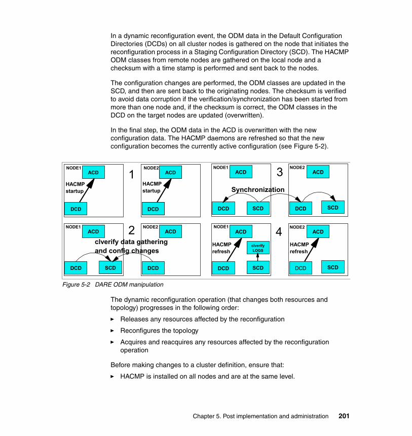
In a dynamic reconfiguration event, the ODM data in the Default Configuration Directories (DCDs) on all cluster nodes is gathered on the node that initiates the reconfiguration process in a Staging Configuration Directory (SCD). The HACMP ODM classes from remote nodes are gathered on the local node and a checksum with a time stamp is performed and sent back to the nodes.
The configuration changes are performed, the ODM classes are updated in the SCD, and then are sent back to the originating nodes. The checksum is verified to avoid data corruption if the verification/synchronization has been started from more than one node and, if the checksum is correct, the ODM classes in the DCD on the target nodes are updated (overwritten).
In the final step, the ODM data in the ACD is overwritten with the new configuration data. The HACMP daemons are refreshed so that the new configuration becomes the currently active configuration (see Figure 5-2).
Figure 5-2 DARE ODM manipulation
The dynamic reconfiguration operation (that changes both resources and topology) progresses in the following order:
� Releases any resources affected by the reconfiguration
� Reconfigures the topology
� Acquires and reacquires any resources affected by the reconfiguration operation
Before making changes to a cluster definition, ensure that:
� HACMP is installed on all nodes and are at the same level.
DCD
ACDNODE1
DCD
ACDNODE2
DCD
ACD
SCD
NODE1
DCD
ACDNODE2
clverify data gatheringand config changes
DCD
ACDNODE1
DCD
ACDNODE2
DCD
ACD
SCD
NODE1
DCD
ACDNODE2
SCD
clverifyLOGS
Synchronization
1
2
3
4
HACMPstartup
HACMPstartup
HACMPrefresh
HACMPrefresh
SCD
SCD
Chapter 5. Post implementation and administration 201

� All nodes are available (up and running) and able to communicate with each other. Even if cluster services may not be running on a cluster node, reconfiguration is possible from another node that has the cluster services active.
� The cluster is in a stable state; no recent event errors or config_too_long messages exist.
Synchronizing configuration changesWhen you change the topology or the resources of a cluster, HACMP updates the data stored in the ODM in the DCD (/etc/es/objrepos). Synchronization causes the information stored in the DCD on the local cluster node to be copied to the ODM object classes in the DCD on the other cluster nodes.
When synchronizing the cluster, a dynamic reconfiguration event is triggered, and HACMP verifies that both cluster topology and cluster resources are correctly configured, even though you may have only modified only one of them.
Since a change in topology may invalidate the resource configuration and vice versa, the software checks both.
Dynamic cluster topology changes
You can make the following changes to the cluster topology in an active cluster dynamically:
� Adding or removing nodes� Adding or removing network interfaces� Swapping a network interface card (for hardware replacement)� Changing network module tuning parameters� Adding a new network
Note: No node may be in a forced down state during DARE operations. This may affect resource group availability and/or corrupt data.
Note: In HACMP V5.1, DARE has been significantly improved to support resource and topology changes in one operation.
Important: To avoid unnecessary processing of resources, we recommend you move resource groups that will be affected by the change before you make the change (using the clRGmove command).
When dynamically reconfiguring a cluster, HACMP will release resource groups if this is found to be necessary, and they will be reacquired later.
202 IBM Eserver pSeries HACMP V5.x Certification Study Guide Update

The following topology and RG changes cannot be dynamically performed without stopping HACMP services, taking the application offline, or rebooting a node:
� Topology Changes
– Change the name of the cluster.
– Change the cluster ID.
– Change the name of a cluster node.
– Change the attributes of a communication interface.
– Changing a network from IPAT via IP aliasing to via IPAT replacement and vice-versa.
– Change the name of a network module.
– Add a network interface module.
– Removing a network interface module.
– Any other changes that need complete reconfiguration of the RSCT peer domain (topology and group services) on which the cluster manager relies.
� Resource Changes
– Change the name of a resource group.
– Change the name of an application server.
– Change the node relationship.
If a dynamic reconfiguration should fail due to an unexpected cluster event, then the staging configuration directory (SCD) might still exist. This prevents further changes being made to the cluster.
If a node failure should occur during a synchronization process, the Staging Configuration Directory (SCD) will not be cleared on all nodes.
The presence of the SCD prevents further configuration changes from being performed. If the SCD is not cleared at the end of a synchronization, this indicates that the DARE operation did not complete; hence, the SCD acts as a lock against further changes.
You can observe that the DCD copies are made to SCDs before the change is copied by each node’s cluster manager into each node’s ACD. If there is an SCD when HACMP starts up on a node, this is copied to the ACD, the SCD is deleted, and the new ACD is used.
If a node failure has occurred at any time during DARE, and there are “leftover” SCDs on some of the nodes, the SCDs must be removed before HACMP is
Chapter 5. Post implementation and administration 203

restarted on any node (or you risk different cluster nodes running with different configurations, a situation which will result in one or more cluster nodes crashing).
To recover from this situation, you must use the Release Locks Set By Dynamic Reconfiguration SMIT menu. This clears the remaining SCDs and allows further cluster synchronizations. If an SCD exists on any cluster node, then no further synchronizations will be permitted until this is deleted.
To clear the DARE locks, use the following procedure, as shown in the following examples, starting with Example 5-1.
Example 5-1 Problem Determination Tools screen
HACMP for AIX
Move cursor to desired item and press Enter.
Initialization and Standard Configuration Extended Configuration System Management (C-SPOC) Problem Determination Tools
F1=Help F2=Refresh F3=Cancel F8=ImageF9=Shell F10=Exit Enter=Do
To release the DARE locks, use the HACMP problem determination tools menu shown in Example 5-2.
Example 5-2 Release Lock Set DARE screen
Problem Determination Tools
Move cursor to desired item and press Enter.
HACMP Verification View Current State HACMP Log Viewing and Management Recover From HACMP Script Failure Restore HACMP Configuration Database from Active Configuration Release Locks Set By Dynamic Reconfiguration Clear SSA Disk Fence Registers HACMP Trace Facility HACMP Event Emulation HACMP Error Notification
Open a SMIT Session on a Node
204 IBM Eserver pSeries HACMP V5.x Certification Study Guide Update

F1=Help F2=Refresh F3=Cancel F8=ImageF9=Shell F10=Exit Enter=Do
Wait for command completion and successfully finish (see Example 5-3). If this operation does not succeed you cannot proceed further, and support intervention may be needed.
Example 5-3 Check status release DARE lock screen
COMMAND STATUS
Command: OK stdout: yes stderr: no
Before command completion, additional instructions may appear below.
cldare: Succeeded removing all DARE locks.
f1=Help F2=Refresh F3=Cancel F6=CommandF8=Image F9=Shell F10=Exit /=Findn=Find Next
To perform the same operation in a single step, you can also use the /usr/es/sbin/cluster/utilities/cldare -u command.
5.1.4 Managing users and groupsIn HACMP, C-SPOC allows you to manage users and groups (create and change the characteristics). A new option was introduced in HACMP V5.1: now you can also change the user passwords via C-SPOC.
When creating an user or a group, you can select the nodes by resource group, or you can specify individual nodes or all nodes in the cluster.
Before using HACMP to change user passwords, the following prerequisites should be checked:
� All nodes must have HACMP V5.1 installed.
� Cluster topology is configured.
� The user account must exist on every cluster node in the list.
Note: In HACMP V5.1, only the root user can change the users’ passwords.
Chapter 5. Post implementation and administration 205

� The user account must exist on the local node. (The password will change on the local node, even if that node is not in the selected nodelist or resource group.)
� AIX must be running on all cluster nodes and all nodes must be able to communicate via clcomdES.
The user management is accessible via HACMP C-SPOC menus or using the following SMIT fast path:
# smitty cl_usergroup
The screen in Example 5-4 should appear.
Example 5-4 Selecting passwords option
HACMP Security and Users Management
Move cursor to desired item and press Enter.
Change/Show HACMP Security Mode Users in an HACMP cluster Groups in an HACMP cluster Passwords in an HACMP cluster
F1=Help F2=Refresh F3=Cancel F8=ImageF9=Shell F10=Exit Enter=Do
To change a user’s password, use the menu shown in Example 5-5.
Example 5-5 Change user password
Passwords in an HACMP cluster
Move cursor to desired item and press Enter.
Change a User's Password in the Cluster
F1=Help F2=Refresh F3=Cancel F8=ImageF9=Shell F10=Exit Enter=Do
You can select the resources group (the node set to which the user belongs), and specify the name of the user, as shown in Example 5-6 on page 207.
206 IBM Eserver pSeries HACMP V5.x Certification Study Guide Update

Example 5-6 Selecting nodes and users
Change a User's Password in the Cluster
Type or select values in entry fields.Press Enter AFTER making all desired changes.
[Entry Fields] Selection nodes by resource group customrg *** No selection means all nodes! **** User NAME [userp630n01] + User must change password on first login? true +
F1=Help F2=Refresh F3=Cancel F4=ListF5=Reset F6=Command F7=Edit F8=ImageF9=Shell F10=Exit Enter=Do
Enter the user name and the current password, then change the password, as shown in Example 5-7.
Example 5-7 Password change screen
COMMAND STATUS
Command: running stdout: no stderr: no
Before command completion, additional instructions may appear below.
userp630n01's New password:Enter the new password again:
For more information, see Chapter 14, “Managing Users, Groups, and Security in a Cluster”, in the HACMP for AIX 5L V5.1 Adminstration and Troubleshooting Guide, SC23-4862-02.
Note: Consider the following options:
� Selecting the nodes by resource group
If you leave the field blank, all nodes in the cluster are selected by default.
� User must change Password on first login?
If set to true, the user will be required to change the password on each node on the next log in. If set to false, the user will not be required to change the password on the next log in. The default is true.
Chapter 5. Post implementation and administration 207

5.1.5 Managing cluster storage using C-SPOC LVM Changes to the LVM components are the most frequent type of changes in a cluster. The following operations can be performed using C-SPOC:
� For shared volume groups:
– Enabling fast disk takeover
– Creating a shared volume group
– Extending a shared volume group
– Importing a shared volume group
– Reducing a shared volume group
– Making a copy of a volume group
– Removing a copy of a volume group
– Mirroring a volume group
– Unmirroring a volume group
– Removing a shared volume group
– Synchronizing volume group mirrors
� For shared logical volumes:
– Adding or removing a shared logical volume
– Changing a shared logical volume (renaming, extending, adding, or removing a copy)
� For shared file systems:
– Creating a shared file system
– Changing a shared file system
– Removing a shared file system
� For shared physical volumes:
– Adding a disk definition to cluster nodes
– Removing a disk definition on cluster nodes
– Replacing a cluster disk
– Managing Data Path Devices
Note: Regarding increasing or decreasing the number of copies (mirrors) of a shared logical volume: This task does not apply to RAID devices.
208 IBM Eserver pSeries HACMP V5.x Certification Study Guide Update

After exporting and importing, a volume group is owned by root and accessible by the system group. Applications, such as some database servers, that use raw logical volumes, may be affected by this if the ownership of the raw logical volumes changes to root.system. You must restore the ownership and permissions back to the ones needed by the application after this sequence.
In HACMP V5.1, C-SPOC also uses the AIX 5L V5.1 CLVM capabilities that allow changes to concurrent LVM components without stopping and restarting the cluster.
� For shared concurrent volume groups:
– Create a concurrent volume group on selected cluster nodes (using hdisks or data path devices).
– Convert SSA concurrent or RAID concurrent volume groups to enhanced concurrent mode.
– List all concurrent volume groups in the cluster.
– Import a concurrent volume group.
– Extend a concurrent volume group.
– Reduce a concurrent volume group.
– Mirror a concurrent volume group.
– Unmirror a concurrent volume group.
– Synchronize concurrent LVM mirrors by volume group.
In HACMP V5.1, both concurrent SSA and RAID VGs, and enhanced concurrent VGs, are supported; however, the SSA and RAID concurrent VGs are only supported with the 32-bit AIX kernel.
Moreover, it is not possible to create new SSA and RAID concurrent VGs in AIX 5L V5.2. We recommend that all existing concurrent VGs (SSA and RAID) be migrated to enhanced concurrent VGs.
Since the enhanced concurrent VGs use RSCT group services communication for the concurrent mechanism, they can be varied on in concurrent mode only if
Tip: When performing any of these maintenance tasks on shared LVM components, make sure that ownership and permissions are returned to the original when a volume group is exported and then re-imported.
Note: To perform these tasks, the volume group must be varied on in concurrent mode.
Chapter 5. Post implementation and administration 209

an RSCT cluster exists and is on line (HACMP V5.1 is Enhanced Scalability, so it uses RSCT topology and group services).
The following section shows how to create a concurrent VG in a cluster using C-SPOC.
Creating a concurrent VG (SSA and RAID)Before creating a concurrent volume group for the cluster using C-SPOC, check the following:
� All disk devices are properly attached to the cluster nodes.
� All disk devices are properly configured on all cluster nodes and listed as available on all nodes.
� The cluster concurrent logical volume manager is installed.
� All disks that will be part of the volume group are concurrent capable.
� You have assigned unique non-zero node numbers on SSA disk subsystems.
To create a concurrent VG, use the smitty cl_convg fast path, as in Example 5-8.
Example 5-8 Creating concurrent volume group
Concurrent Volume Groups
Move cursor to desired item and press Enter.
List All Concurrent Volume Groups Create a Concurrent Volume Group Create a Concurrent Volume Group with Data Path Devices Set Characteristics of a Concurrent Volume Group Import a Concurrent Volume Group Mirror a Concurrent Volume Group Unmirror a Concurrent Volume Group
F1=Help F2=Refresh F3=Cancel F8=ImageF9=Shell F10=Exit Enter=Do
Select the nodes where the concurrent volume group will be create (see Example 5-9 on page 211).
210 IBM Eserver pSeries HACMP V5.x Certification Study Guide Update

Example 5-9 Selecting nodes
Concurrent Volume Groups
Move cursor to desired item and press Enter.
List All Concurrent Volume Groups Create a Concurrent Volume Group Create a Concurrent Volume Group with Data Path Devices Set Characteristics of a Concurrent Volume Group Import a Concurrent Volume Group +--------------------------------------------------------------------------+ ¦ Node Names ¦ ¦ ¦ ¦ Move cursor to desired item and press F7. ¦ ¦ ONE OR MORE items can be selected. ¦ ¦ Press Enter AFTER making all selections. ¦ ¦ ¦ ¦ > p630n01 ¦ ¦ > p630n02 ¦ ¦ p630n03 ¦ ¦ ¦ ¦ F1=Help F2=Refresh F3=Cancel ¦ ¦ F7=Select F8=Image F10=Exit ¦F1¦ Enter=Do /=Find n=Find Next ¦F9+--------------------------------------------------------------------------+
Select the physical volumes that you want to use (Example 5-10).
Example 5-10 Selecting physical volume
Concurrent Volume Groups
Mo+--------------------------------------------------------------------------+ ¦ Physical Volume Names ¦ ¦ ¦ ¦ Move cursor to desired item and press F7. ¦ ¦ ONE OR MORE items can be selected. ¦ ¦ Press Enter AFTER making all selections. ¦ ¦ ¦ ¦ [TOP] ¦ ¦ > 0000331209edfd3c ¦ ¦ > 0006856f4b43faac ¦ ¦ > 0006850ff6246caa ¦ ¦ 0000331209edfe88 ¦ ¦ 000685bf3330aa97 ¦ ¦ 000685cf28cb8d72 ¦ ¦ 000685bf4b4b6f1a ¦ ¦ 0006850ff6246dd7 ¦
Chapter 5. Post implementation and administration 211

¦ [MORE...12] ¦ ¦ ¦ ¦ F1=Help F2=Refresh F3=Cancel ¦ ¦ F7=Select F8=Image F10=Exit ¦F1¦ Enter=Do /=Find n=Find Next ¦F9+--------------------------------------------------------------------------+
Chose the name of the new concurrent volume group (Example 5-11).
Example 5-11 Create concurrent volume group
Create a Concurrent Volume Group
Type or select values in entry fields.Press Enter AFTER making all desired changes.
[TOP] [Entry Fields] Node Names p630n01,p630n02 PVID 0000331209edfd3c 0006> VOLUME GROUP name [concvg01] Physical partition SIZE in megabytes 16 + Volume group MAJOR NUMBER [101] +# Enhanced Concurrent Mode true +
Warning :[MORE...10]
F1=Help F2=Refresh F3=Cancel F4=ListF5=Reset F6=Command F7=Edit F8=ImageF9=Shell F10=Exit Enter=Do
Check for success, as seen in Example 5-12.
Example 5-12 Create concurrent status
COMMAND STATUS
Command: OK stdout: yes stderr: no
Before command completion, additional instructions may appear below.
p630n01: concvg01p630n01: p630n02: Volume group concvg01 has been imported.
F1=Help F2=Refresh F3=Cancel F6=CommandF8=Image F9=Shell F10=Exit /=Find
212 IBM Eserver pSeries HACMP V5.x Certification Study Guide Update

n=Find Next
After the concurrent volume group has been created, you also can verify the /tmp/cspoc.log file for additional messages.
After creating the concurrent VG, you need to add it into a resource group; otherwise, you will not be able to use this VG to create concurrent logical volumes (used as raw devices for the applications). For details, see 5.2.3, “Changing resource groups” on page 219.
You also can perform changes to the LVM components using:
� Manual update
� Lazy update
Manual updateYou can perform changes in the LVM components in the cluster manually, outside of the control of HACMP. In this case, you should make sure as soon as possible that the updates are made on all nodes in the cluster.
When changing the LVM components, we recommend that you follow these procedures:
1. Stop the cluster services on the node owning the shared volume group (sometimes just stopping the applications may be enough).
2. Make the changes to the shared LVM components.
3. Unmount all the file systems belonging to the shared volume group.
4. Varyoff the shared volume group.
5. Export the volume group definition on the other nodes (alternately, you can use the importvg -L command without exporting the VG definition).
6. Import the volume group again to the other node to update the AIX ODM, and, if you are using NFS mounts, make sure that you are using the same Major Number.
7. Change the characteristics of the volume group needs.
8. Varyoff the volume group of this node.
9. Start the cluster services again on the node with the highest priority (home node) for the resource group.
Lazy update For LVM components under the control of HACMP for AIX, you do not have to explicitly export and import to bring the other cluster nodes up to date. Instead, HACMP for AIX can perform the export and import when it activates the volume
Chapter 5. Post implementation and administration 213
group during a failover. (In a cluster, HACMP controls when volume groups are activated.) HACMP for AIX implements a function, named “lazy update”, by keeping a copy of the VGDA time stamp for the shared volume groups.
AIX updates the VGDA time stamp whenever a LVM component is modified. When another cluster node attempts to varyon the volume group, HACMP for AIX compares its copy of the VGDA time stamp with the time stamp in the VGDA on the disk. If the values are different, HACMP exports and re-imports the volume group before activating it. If the time stamps are the same, HACMP activates the volume group normally (without exporting and re-importing).
5.2 Managing resource groupsThis section describes how to manage the resource groups in a HACMP cluster. Some of the most common operations are:
� Moving resource groups between nodes
� Adding and deleting resource groups
� Modifying resource groups (adding and deleting resources)
� Configuring resource groups processing order
� Configuring resource groups run-time parameters (timers and so on)
HACMP V5.1 has new features for manipulating resource groups. These new features are:
� Resource Group Management Utility
� Replacing the STICKY attribute with Priority Override Location for resource groups.
� Resource group settling timers
� Timed fallback of the resource groups
Note: HACMP V5.1 does not require lazy update processing for enhanced concurrent volume groups, as it keeps all nodes in the resource group updated with the LVM information.
214 IBM Eserver pSeries HACMP V5.x Certification Study Guide Update

5.2.1 Resource group movementHere we discuss the movement of resource groups.
Replacing the DARE resource migration
The new Resource Group Management utility (clRGmove) allows users to:
� Bring a Resource Group Online� Bring a Resource Group Offline� Move a Resource Group to Another Node
When the clRGmove command is run, an rg_move event is queued to carry out the requested operation. The Priority Override Location (POL) for a resource group is set when any of the above operations are performed.
5.2.2 Priority Override Location (POL)In previous versions of HACMP, managing resource group locations required the resource reconfiguration event (cldare -M).
Resource group location can be changed for various reasons, but is especially useful during maintenance operations. Once a resource group has been moved (the movement is initiated manually) we want to make sure that the resource group maintains its status (designated node and status).
Previously, in HACMP V4.5, the STICKY attribute was used for specifying RG behavior in such a case. It was difficult for users to understand the use of the STICKY RG attribute. Moreover, even after an RG was moved, it could return to its default location automatically.
HACMP V5.1 introduces a new mechanism for Resource Group Management, the clRGmove utility.
� clRGmove tells the cluster manager to queue an rg_move event.
� These rg_move events are faster than the old DARE method.
� Resource group locations are easier to manage and understand.
� Event processing is more straightforward, and specific to RG movement.
Note: In HACMP V5.1, the DARE resource migration facility has been replaced with the resource group management utility.
Chapter 5. Post implementation and administration 215

HACMP V4.5 used the STICKY RG attribute to maintain the location and/or state of a RG:
� The STICKY attribute was set when the customer used DARE to move, start, or stop an RG.
� If the STICKY attribute was set, the RG condition would be maintained through cluster restart.
� If the STICKY attribute was not set, an RG that had been moved, started, or stopped could move to a higher priority node.
HACMP V5.1 uses the Priority Override Location (POL) setting to maintain the location and/or state of a RG:
� Under normal operating conditions, a resource group does not have a POL.
� If the system administrator/user initiates a manual operation on a resource group (to bring it online, offline, or move it to another node), the resource group gets the POL attribute.
� The POL refers to the requested state (online/offline) and location of a resource group (specified during manual operation).
� Users may specify that a POL should be persistent, meaning that it will be retained when the cluster is restarted on all nodes.
� The POL determines the RG behavior:
– A resource group that is offline with a POL will remain offline.
– A POL remains in effect until canceled.
– A non-persistent POL remains in force as long as at least one cluster node is active.
– Non-persistent POLs are implicitly canceled if all the HACMP daemons on all the nodes in the cluster are shutdown.
You should always use the POL when the resource group management is performed. If the POL is not set on the resource group, any other node in the resource group can be brought online, even if the node with highest priority fails.
For example, in a cluster with four nodes, if the cluster services have been stopped “gracefully” for maintenance reasons on one node (for example, another node on the same RG fails), the resource group will be acquired by another available node (because the resource group is found offline when cluster reconfiguration occurs).
We can avoid unwanted acquisition of the RG by setting the POL for that resource group on the node that has the highest priority (and has been brought
216 IBM Eserver pSeries HACMP V5.x Certification Study Guide Update

down “gracefully”). This POL remains on even if the cluster services were stopped.
When using SMIT panels to move a resource group, you can also specify that RG status and location should persist across a cluster reboot. If you leave this flag to the default (false), the destination node that you specify does not become a POL for the resource group, and the resource group will fall back to its default behavior after you stop and restart the cluster services on all nodes (cluster reboot).
If you set this flag to true (persist across cluster reboot), the destination node and status of the RG becomes a POL for this resource group. That is, once the resource group is moved to the specified destination node, it stays on that node after a cluster reboot.
Example 5-13 Setting persistent POL
Move a Resource Group
Type or select values in entry fields.Press Enter AFTER making all desired changes.
[Entry Fields] Resource Group to be Moved customrg Destination Node p630n02 Persist Across Cluster Reboot? true +
F1=Help F2=Refresh F3=Cancel F4=ListF5=Reset F6=Command F7=Edit F8=ImageF9=Shell F10=Exit Enter=Do
The result should look similar to Example 5-14.
Example 5-14 Setting POL
COMMAND STATUS
Command: OK stdout: yes stderr: no
Before command completion, additional instructions may appear below.
Attempting to move group customrg to node p630n02.
Waiting for cluster to process the resource group movement request.....
Waiting for the cluster to stabilize.......
Resource group movement successful.
Chapter 5. Post implementation and administration 217

Resource group customrg is online on node p630n02.
Distributing persistent priority override location informationto all accessible nodes.-----------------------------------------------------------------------------Group Name Type State Location Priority Override-----------------------------------------------------------------------------customrg custom OFFLINE p630n01 p630n02 (PERSISTENT) ONLINE p630n02 p630n02 (PERSISTENT)
F1=Help F2=Refresh F3=Cancel F6=CommandF8=Image F9=Shell F10=Exit /=Findn=Find Next
To verify the success of this operation, you can use the clRGinfo command (see Example 5-15).
Example 5-15 clRGinfo -p command
[p630n01]/usr/es/sbin/cluster/utilities/clRGinfo -p-----------------------------------------------------------------------------Group Name Type State Location Priority Override-----------------------------------------------------------------------------rg01 cascading ONLINE p630n01 OFFLINE p630n02 OFFLINE p630n03>>>>>>>>>>>>>> Omitted lines <<<<<<<<<<<<<<
rg05 cascading OFFLINE p630n01 OFFLINE (PERSISTENT) OFFLINE p630n02 OFFLINE (PERSISTENT) OFFLINE p630n03 OFFLINE (PERSISTENT)>>>>>>>>>>>>>> Omitted lines <<<<<<<<<<<<<<
customrg custom OFFLINE p630n01 p630n02 (PERSISTENT) ONLINE p630n02 p630n02 (PERSISTENT)
When the POL bit is set, it is stored in the /usr/es/sbin/cluster/etc/clpol file. If the bit is not set, the file will be empty.
The data representation in this file is numeric, and is not normally viewed or changed by end users. You can, however, clear all persistent POLs on an inactive cluster by simply emptying the clpol file on each node (see Example 5-16).
Example 5-16 Emptying the POL file
[p630n01] /# > /usr/es/sbin/cluster/etc/clpol
218 IBM Eserver pSeries HACMP V5.x Certification Study Guide Update
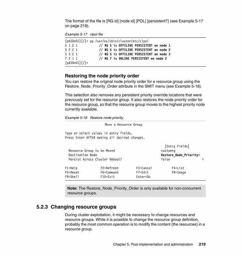
The format of the file is [RG id] [node id] [POL] [persistent?] (see Example 5-17 on page 219).
Example 5-17 clpol file
[p630n01][/]> pg /usr/es/sbin/cluster/etc/clpol5 1 2 1 // RG 5 is OFFILINE PERSISTENT on node 15 2 2 1 // RG 5 is OFFILINE PERSISTENT on node 25 3 2 1 // RG 5 is OFFILINE PERSISTENT on node 37 2 1 1 // RG 7 is ONLINE PERSISTENT on node 2[p630n01][/]>
Restoring the node priority orderYou can restore the original node priority order for a resource group using the Restore_Node_Priority_Order attribute in the SMIT menu (see Example 5-18).
This selection also removes any persistent priority override locations that were previously set for the resource group. It also restores the node priority order for the resource group, so that the resource group moves to the highest priority node currently available.
Example 5-18 Restore node priority
Move a Resource Group
Type or select values in entry fields.Press Enter AFTER making all desired changes.
[Entry Fields] Resource Group to be Moved customrg Destination Node Restore_Node_Priority> Persist Across Cluster Reboot? false +
F1=Help F2=Refresh F3=Cancel F4=ListF5=Reset F6=Command F7=Edit F8=ImageF9=Shell F10=Exit Enter=Do
5.2.3 Changing resource groupsDuring cluster exploitation, it might be necessary to change resources and resource groups. While it is possible to change the resource group definition, probably the most common operation is to modify the content (the resources) in a resource group.
Note: The Restore_Node_Priority_Order is only available for non-concurrent resource groups.
Chapter 5. Post implementation and administration 219

This can be achieved via SMIT menus, using either standard or extended configuration. In standard menus, the changes that can be made to a resource group are limited, while when using extended path, one can fine-tune resources and resource group behavior.
This section describes some examples of how to use the HACMP Extended SMIT menus for changing resource group composition, behavior, and attributes.
To change resources, run smitty hacmp and select Extended Configuration → Extended Resource Configuration (see Example 5-19).
Example 5-19 Changing resource groups (extended)
Extended Resource Configuration
Move cursor to desired item and press Enter.
HACMP Extended Resources Configuration Configure Resource Group Run-Time Policies HACMP Extended Resource Group Configuration
F1=Help F2=Refresh F3=Cancel F8=ImageF9=Shell F10=Exit Enter=Do
Select the Change/Show Resources and Attributes for a Resource Group option (see Example 5-20).
Example 5-20 Resource group attributes menu
HACMP Extended Resource Group Configuration
Move cursor to desired item and press Enter.
Add a Resource Group Change/Show a Resource Group Change/Show Resources and Attributes for a Resource Group Remove a Resource Group Show All Resources by Node or Resource Group
F1=Help F2=Refresh F3=Cancel F8=ImageF9=Shell F10=Exit Enter=Do
Select the resource group to change and press Enter (see Example 5-21 on page 221).
220 IBM Eserver pSeries HACMP V5.x Certification Study Guide Update

Example 5-21 Resource group selection
HACMP Extended Resource Group Configuration
Move cursor to desired item and press Enter.
Add a Resource Group Change/Show a Resource Group Change/Show Resources and Attributes for a Resource Group +--------------------------------------------------------------------------+ ¦ Change/Show Resources and Attributes for a Resource Group ¦ ¦ ¦ ¦ Move cursor to desired item and press Enter. ¦ ¦ ¦ ¦ customrg ¦ ¦ rg01 ¦ ¦ rg02 ¦ ¦ rg03 ¦ ¦ ¦ ¦ F1=Help F2=Refresh F3=Cancel ¦ ¦ F8=Image F10=Exit Enter=Do ¦F1¦ /=Find n=Find Next ¦F9+--------------------------------------------------------------------------+
Now you can modify the resource group characteristics (see Example 5-22).
Example 5-22 Changing the resource group attributes
Change/Show All Resources and Attributes for a Custom Resource Group
Type or select values in entry fields.Press Enter AFTER making all desired changes.
[TOP] [Entry Fields] Resource Group Name customrg Resource Group Management Policy custom Inter-site Management Policy ignore Participating Node Names (Default Node Priority) p630n01 p630n02
Startup Behavior Online On Home Node O> Fallover Behavior Fallover To Next Prio> Fallback Behavior Fallback To Higher Pr> Fallback Timer Policy (empty is immediate) [customofallb] +
Service IP Labels/Addresses [] + Application Servers [] +
Volume Groups [customvg] + Use forced varyon of volume groups, if necessary false +
Chapter 5. Post implementation and administration 221

Automatically Import Volume Groups false + Filesystems (empty is ALL for VGs specified) [] + Filesystems Consistency Check fsck + Filesystems Recovery Method sequential + Filesystems mounted before IP configured false + Filesystems/Directories to Export [] + + Filesystems/Directories to NFS Mount [] + Network For NFS Mount [] +Tape Resources [] + Raw Disk PVIDs [] +
Fast Connect Services [] + Communication Links [] +
Primary Workload Manager Class [] + Secondary Workload Manager Class [] +
Miscellaneous Data []
F1=Help F2=Refresh F3=Cancel F4=ListF5=Reset F6=Command F7=Edit F8=ImageF9=Shell F10=Exit Enter=Do
Configuring resource group processing orderingThis feature is useful in a cluster with multiple application servers that may depend on each other, and should be started and stopped in a specific sequence.
By default, HACMP acquires and releases resource groups in parallel. If you have migrated from versions of HACMP previous to V4.5, alphabetical processing order may be retained.
Resource groups acquisition in HACMP V5.1 occurs in the following order:
� Those resource groups for which the customized order is specified are acquired in the specified serial order.
� Resource groups that must contain NFS file systems only are also processed in the specified order.
� Resource groups that are not included in the customized order lists are acquired in parallel.
Resource groups release in HACMP V5.1 occurs in the following order:
� Those resource groups for which no customized order are released in parallel.
222 IBM Eserver pSeries HACMP V5.x Certification Study Guide Update

� HACMP releases resource groups that are included in the customized release ordering list.
� Resource groups that must unmount NFS file systems are processed in the specified order.
Serial processing � You must define resource groups in a way that prevents dependencies
between them.
� You should specify the same customized serial processing order on all nodes in the cluster. For this task, you need to specify the order on one node and synchronize cluster resources to propagate the change to the other nodes in the cluster.
� If you have a specified serial processing order for resource groups, and if in some of the resource groups the NFS cross-mount takes place during the acquisition (node_up event) or release (node_down event), then HACMP automatically processes these resource groups after other resource groups in the list.
� If you remove a resource group that has been included in a customized serial ordering list, then the name of that resource group is automatically removed from the processing order list. If you change a name of a resource group, the list is updated appropriately.
Parallel processing Resource groups that have sites defined cannot be processed in parallel. Make sure that such resource groups are specified in the customized serial order.
If you decide at a point in time to change from sequential processing order to parallel processing, and if you have pre- and post-event scripts configured for specific cluster events, you may need to change them, as they may no longer produce expected results.
To change the RG processing order, run smitty hacmp and select Extended Configuration → Configure Resource Group Run-Time Policies (see Example 5-23 on page 224).
Chapter 5. Post implementation and administration 223

Example 5-23 RG processing order
Configure Resource Group Run-Time Policies
Move cursor to desired item and press Enter.
Configure Resource Group Processing Ordering Configure Dynamic Node Priority Policies Configure HACMP Workload Manager Parameters Configure Delayed Fallback Timer Policies Configure Settling Time for Resource Groups
F1=Help F2=Refresh F3=Cancel F8=ImageF9=Shell F10=Exit Enter=Do
Type in the new processing order for the resources groups (see Example 5-24).
Example 5-24 Changing the processing order
Change/Show Resource Group Processing Order
Type or select values in entry fields.Press Enter AFTER making all desired changes.
[Entry Fields]
Resource Groups Acquired in Parallel customrg rg01 rg02 rg> Serial Acquisition Order New Serial Acquisition Order [rg02 customrg rg01] +
Resource Groups Released in Parallel customrg rg01 rg02 rg> Serial Release Order New Serial Release Order [rg01 customrg rg02] +
F1=Help F2=Refresh F3=Cancel F4=ListF5=Reset F6=Command F7=Edit F8=ImageF9=Shell F10=Exit Enter=Do
224 IBM Eserver pSeries HACMP V5.x Certification Study Guide Update

5.2.4 Creating a new resource groupAdding a new resource group may be necessary to expand cluster functionality with additional applications. Although it is possible to add new resource groups using either HACMP standard or extended menus, in this section we present the extended configuration path.
To add a new resource group, run smitty hacmp and select Extended Configuration → Extended Resource Configuration → HACMP Extended Resource Group Configuration -> Add a Resource Group (see Example 5-25).
Example 5-25 Choosing RG type
HACMP Extended Resource Group Configuration
Move cursor to desired item and press Enter.
Add a Resource Group Change/Show a Resource Group Change/Show Resources and Attributes for a Resource Group Remove a Resource Group Show All Resources by Node or Resource Group
+--------------------------------------------------------------------------+ ¦ Select a Resource Group Management Policy ¦ ¦ ¦ ¦ Move cursor to desired item and press Enter. ¦ ¦ ¦ ¦ Cascading ¦ ¦ Rotating ¦ ¦ Concurrent ¦ ¦ Custom ¦ ¦ ¦ ¦ F1=Help F2=Refresh F3=Cancel ¦ ¦ F8=Image F10=Exit Enter=Do ¦F1¦ /=Find n=Find Next ¦F9+--------------------------------------------------------------------------+
Type in a name for the new resource group and select the nodes that can “hold” this RG, and any additional parameters. We recommend that you use the “custom” type for any new resource group (except when IPAT via replacement is required).
Select the nodes (see Example 5-26 on page 226).
Chapter 5. Post implementation and administration 225

Example 5-26 Defining a custom resource group
Add a Custom Resource Group (extended)
Type or select values in entry fields.Press Enter AFTER making all desired changes.
[Entry Fields]* Resource Group Name [db_rg] Inter-Site Management Policy [ignore] +* Participating Node Names (Default Node Priority) [] + +--------------------------------------------------------------------------+ ¦ Participating Node Names (Default Node Priority) ¦ ¦ ¦ ¦ Move cursor to desired item and press F7. ¦ ¦ ONE OR MORE items can be selected. ¦ ¦ Press Enter AFTER making all selections. ¦ ¦ ¦ ¦ p630n01 ¦ ¦ p630n02 ¦ ¦ p630n03 ¦ ¦ ¦ ¦ F1=Help F2=Refresh F3=Cancel ¦F1¦ F7=Select F8=Image F10=Exit ¦F5¦ Enter=Do /=Find n=Find Next ¦F9+--------------------------------------------------------------------------+
Select the resource group behavior (see Example 5-27).
Example 5-27 Resource group behavior
Add a Custom Resource Group (extended)
Type or select values in entry fields.Press Enter AFTER making all desired changes.
[Entry Fields]* Resource Group Name [db_rg] Inter-Site Management Policy [ignore] +* Participating Node Names (Default Node Priority) [p630n01 p630n02 p630n> +
Startup Policy Online On Home Node O> + Fallover Policy Fallover To Next Prio> + Fallback Policy Fallback To Higher Pr> +
F1=Help F2=Refresh F3=Cancel F4=ListF5=Reset F6=Command F7=Edit F8=Image
226 IBM Eserver pSeries HACMP V5.x Certification Study Guide Update

F9=Shell F10=Exit Enter=Do
For more information about the custom resource groups, see Table 3-3 on page 134.
Keep in mind that when adding a resource group, you are, in fact, just defining a “container” that has to be “populated” with actual resources (service IP addresses, volume groups, file systems, application servers, and so on). For a resource group to become active, the RG must be “populated” with resources, and the cluster must be synchronized.
You can add a resource group with the cluster services up and running. By the time the cluster is synchronized (DARE), the resource group will become online on the designated node.
5.2.5 Bringing a resource group onlineThe resource groups can be brought online when HACMP services are started on all nodes in the cluster, provided that the priority override location (POL) is either not set, or it allows the RG to be brought online.
Before trying to bring the resource group on line, you should verify if the RG has an offline status. If it is online, it cannot be brought online. If it is in the error state, corrective actions may be needed. To verify the RG status, use the clRGinfo command (see Example 5-28).
Example 5-28 Check resource group status
[p630n01]/usr/es/sbin/cluster/utilities/clRGinfo-----------------------------------------------------------------------------Group Name Type State Location-----------------------------------------------------------------------------customrg custom OFFLINE p630n01 OFFLINE p630n02
To bring the resource group online, run smitty cl_admin and select HACMP Resource Group and Application Management → Bring a Resource Group Online (see Example 5-29 on page 228).
Chapter 5. Post implementation and administration 227

Example 5-29 Resource group management menu
HACMP Resource Group and Application Management
Move cursor to desired item and press Enter.
Bring a Resource Group Online Bring a Resource Group Offline Move a Resource Group to Another Node
Suspend/Resume Application Monitoring Application Availability Analysis
F1=Help F2=Refresh F3=Cancel F8=ImageF9=Shell F10=Exit Enter=Do
Select the RG to bring online, and the node where it should be brought up. The selected node will become the Priority Override Location (see Example 5-30).
Example 5-30 Selecting the RG to be brought online
Bring a Resource Group Online
Type or select values in entry fields.Press Enter AFTER making all desired changes.
[Entry Fields] Resource Group to Bring Online customrg Destination Node p630n01 Persist Across Cluster Reboot? false +
F1=Help F2=Refresh F3=Cancel F4=ListF5=Reset F6=Command F7=Edit F8=ImageF9=Shell F10=Exit Enter=Do
Check the SMIT output for successful operation (see Example 5-31 on page 229).
Note: This operation may only be performed on RGs in the offline and error states.
228 IBM Eserver pSeries HACMP V5.x Certification Study Guide Update

Example 5-31 SMIT status screen
COMMAND STATUS
Command: OK stdout: yes stderr: no
Before command completion, additional instructions may appear below.
Attempting to bring group customrg online on node p630n01.
Waiting for cluster to process the resource group movement request.....
Waiting for the cluster to stabilize.....
Resource group movement successful.Resource group customrg is online on node p630n01.
-----------------------------------------------------------------------------Group Name Type State Location Priority Override-----------------------------------------------------------------------------customrg custom ONLINE p630n01 p630n01 OFFLINE p630n02 p630n01
F1=Help F2=Refresh F3=Cancel F6=CommandF8=Image F9=Shell F10=Exit /=Findn=Find Next
For additional messages, check the /tmp/clstrmgr.debug file (see Example 5-32).
Example 5-32 RG status in clstrmgr.debug
Thu Jul 1 12:35:28 RpcPoll: RESMGR RPC request made!Thu Jul 1 12:35:28 got rginfo request.Thu Jul 1 12:35:28 getting resource group info for customrgThu Jul 1 12:35:28 request was successful.Thu Jul 1 12:35:28 group customrg has 2 nodes...Thu Jul 1 12:35:28 node p630n01 (1) state 4 pol 2 pers 0 pol_secondary 0 pers_secondary 0Thu Jul 1 12:35:28 Querying the Timer status for customrg
Thu Jul 1 12:35:28 getGroupTimers: ENTERgetGroupTimers: Processing customrg groupThu Jul 1 12:35:28 No timers currently active for this group.
Thu Jul 1 12:35:28 node p630n02 (2) state 4 pol 2 pers 0 pol_secondary 0 pers_secondary 0Thu Jul 1 12:35:28 Querying the Timer status for customrg
Chapter 5. Post implementation and administration 229

Thu Jul 1 12:35:28 getGroupTimers: ENTERgetGroupTimers: Processing customrg groupThu Jul 1 12:35:28 No timers currently active for this group....********************* RG STATE TABLE *********************
Thu Jul 1 12:38:30 GROUP:[customrg] NODE:[p630n01] STATE:[4]Thu Jul 1 12:38:30 GROUP:[customrg] NODE:[p630n02] STATE:[4]...Thu Jul 1 12:38:30 group=customrg, node=p630n01Thu Jul 1 12:38:30 secondary priority=1Thu Jul 1 12:38:30 group=customrg, node=p630n01, state=4Thu Jul 1 12:38:30 group=customrg, node=p630n02Thu Jul 1 12:38:30 secondary priority=2Thu Jul 1 12:38:30 group=customrg, node=p630n02, state=4...Thu Jul 1 12:40:04 Enter - RevisitRGStatesThu Jul 1 12:40:04 Resetting customrg to 16 on p630n01Thu Jul 1 12:40:04 Resetting customrg to 4 on p630n02...Thu Jul 1 12:40:04 node p630n01 (1) state 16 pol 1 pers 0 pol_secondary 0 pers_secondary 0Thu Jul 1 12:40:04 Querying the Timer status for customrg...
The /tmp/hacmp.out file also contains event and process entries for the resource group brought up (see Example 5-33).
Example 5-33 /tmp/hacmp.out messages
Jul 1 12:39:58 EVENT START: rg_move_acquire p630n01 7Jul 1 12:39:58 EVENT START: rg_move p630n01 7 ACQUIREJul 1 12:39:59 EVENT START: node_up_local...customrg:node_up_local[15] clchdaemons -d clstrmgr_scripts -t resource_locator -n p630n01 -o customrg -v ACQUIRINGcustomrg:node_up_local[15] [[ ACQUIRING = ACQUIRING ]]customrg:node_up_local[15] [[ NONE = ACQUIRE_SECONDARY ]]customrg:node_up_local[15] [[ NONE = PRIMARY_BECOMES_SECONDARY ]]customrg:node_up_local[34] cl_RMupdate acquiring customrg node_up_localReference string: Thu.Jul.1.12:39:59.EDT.2004.node_up_local.customrg.ref...
230 IBM Eserver pSeries HACMP V5.x Certification Study Guide Update

5.2.6 Bringing a resource group offlineWhen you manually bring a resource group offline on a node, the node becomes the resource group’s priority override location (POL). For more information, see 5.2.2, “Priority Override Location (POL)” on page 215.
If Persist Across Cluster Reboot is set to true, then the RG will remain offline, even if the cluster is restarted on all nodes.
There is no option to bring a resource group offline and simultaneously cancel the priority override location.
For non-concurrent resources groups, the POL is set to offline for all nodes in the RG. If you want to bring a concurrent resource group completely offline (or online), select ALL_Nodes_in_Group as the node.
Before you bring the resource group offline, you should verify if the resource group is in the online or error status (see Example 5-28 on page 227).
To bring the RG offline, run smitty cl_admin and select HACMP Resource Group and Application Management → Bring a Resource Group Offline.
Select the resource group to bring offline, and the desired node (all nodes for a concurrent RG) (see Example 5-34).
Example 5-34 RG selection
Bring a Resource Group Offline
Type or select values in entry fields.Press Enter AFTER making all desired changes.
[Entry Fields] Resource Group to Bring Offline customrg Node On Which to Bring Resource Group Offline p630n01 Persist Across Cluster Reboot? false +
F1=Help F2=Refresh F3=Cancel F4=List F5=Reset F6=Command F7=Edit F8=Image F9=Shell F10=Exit Enter=Do
Check the SMIT output screen for verification of a successful operation (see Example 5-35 on page 232).
Note: This operation may only be performed on resource groups in the online and error states.
Chapter 5. Post implementation and administration 231
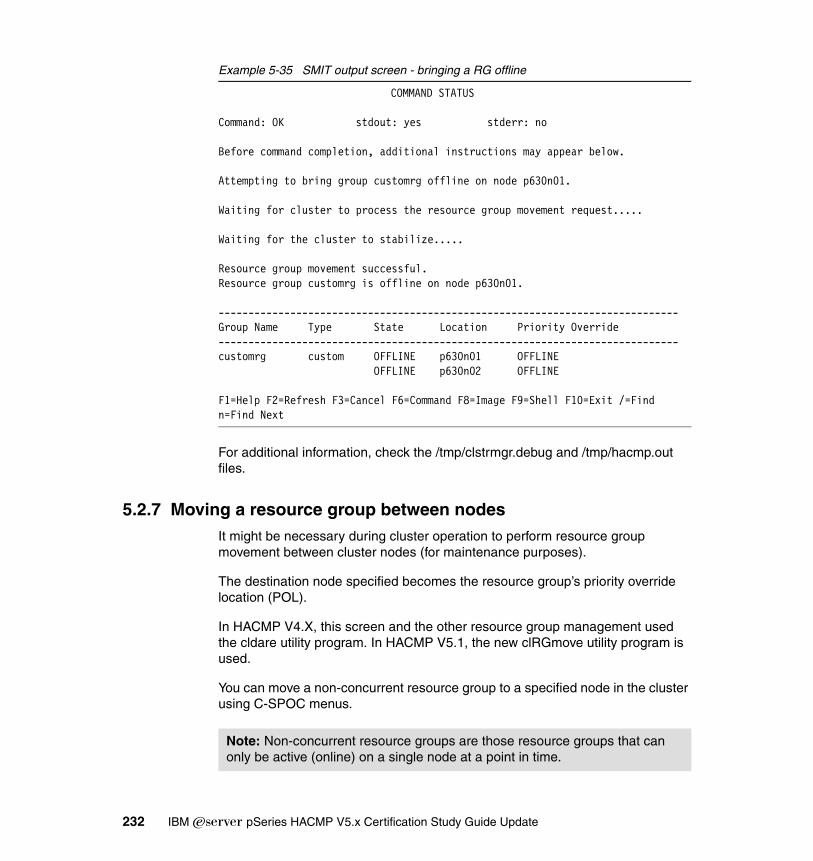
Example 5-35 SMIT output screen - bringing a RG offline
COMMAND STATUS
Command: OK stdout: yes stderr: no
Before command completion, additional instructions may appear below.
Attempting to bring group customrg offline on node p630n01.
Waiting for cluster to process the resource group movement request.....
Waiting for the cluster to stabilize.....
Resource group movement successful.Resource group customrg is offline on node p630n01.
-----------------------------------------------------------------------------Group Name Type State Location Priority Override-----------------------------------------------------------------------------customrg custom OFFLINE p630n01 OFFLINE OFFLINE p630n02 OFFLINE
F1=Help F2=Refresh F3=Cancel F6=Command F8=Image F9=Shell F10=Exit /=Findn=Find Next
For additional information, check the /tmp/clstrmgr.debug and /tmp/hacmp.out files.
5.2.7 Moving a resource group between nodesIt might be necessary during cluster operation to perform resource group movement between cluster nodes (for maintenance purposes).
The destination node specified becomes the resource group’s priority override location (POL).
In HACMP V4.X, this screen and the other resource group management used the cldare utility program. In HACMP V5.1, the new clRGmove utility program is used.
You can move a non-concurrent resource group to a specified node in the cluster using C-SPOC menus.
Note: Non-concurrent resource groups are those resource groups that can only be active (online) on a single node at a point in time.
232 IBM Eserver pSeries HACMP V5.x Certification Study Guide Update

Before you move the resource group, you should verify the RG status. The resource group should be online. You cannot move a resource group that is in the offline or error status (to check the RG status, see Example 5-28 on page 227).
To move a resource group, run smitty cl_admin and select HACMP Resource Group and Application Management → Move a Resource Group to Another Node.
Select an online resource group and the active node to move it to. The new node will become the Priority Override for the resource group. If a resource group has a previously set Priority Override, select Restore_Node_Priority_Order to clear the POL and return it to its default location.
Select the RG to move and verify the SMIT status screen for a successful operation (see Example 5-36).
Example 5-36 SMIT status screen - moving a resource group
COMMAND STATUS
Command: OK stdout: yes stderr: no
Before command completion, additional instructions may appear below.
Attempting to move group customrg to node p630n02.
Waiting for cluster to process the resource group movement request.....
Waiting for the cluster to stabilize.......
Resource group movement successful.Resource group customrg is online on node p630n02.
-----------------------------------------------------------------------------Group Name Type State Location Priority Override-----------------------------------------------------------------------------customrg custom OFFLINE p630n01 p630n02 ONLINE p630n02 p630n02
F1=Help F2=Refresh F3=Cancel F6=CommandF8=Image F9=Shell F10=Exit /=Find
Note: This operation may only be performed on resources groups in the online state.
Chapter 5. Post implementation and administration 233
For additional information and problem determination, see the /tmp/hacmp.out and /tmp/clstrmgr.debug files.
Using the clRGinfo commandIn previous HACMP versions, the command used to find information about the RG status was clfindres. This has been replaced with the clRGinfo command, which returns a report on the location and status of one or more specified resource groups. A resource group can be in any one of the following states (if the sites are configured, there are more possible states):
Online The resource group is currently operating properly on one or more nodes in the cluster.
Offline The resource group is not operating in the cluster and is currently not in an error status.
Acquiring A resource group is currently coming up on one of the nodes in the cluster.
Releasing The resource group is in the process of being released by one node. Under normal conditions, after successful release from a node, the resource group’s status changes to offline.
Error The resource group has reported an error condition. User interaction is required.
Unknown The resource group’s current status cannot be determined due to loss of communication, or because not all nodes in the cluster are up.
5.3 Problem determinationHACMP provides various tools for problem determination. There are problem determination tools and techniques available for every aspect of cluster configuration and operation.
Problem determination in HACMP requires specific skills for all aspects involved in an HACMP cluster:
� IBM ̂pSeries hardware� AIX system administration and problem determination� Networking and TCP/IP� Storage� Application� HACMP
234 IBM Eserver pSeries HACMP V5.x Certification Study Guide Update

The HACMP Problem Determination tools include the following options:
� HACMP verification� Cluster status� HACMP log viewing and management� Recovery from script failure� Restore configuration database from active configuration� Release locks set by dynamic reconfiguration� Clear SSA disk fence registers� HACMP trace facility� Event emulation� Error notification
HACMP also provides SMIT menus for problem determination (see Example 5-37).
Example 5-37 Problem determination tools
Problem Determination ToolsMove cursor to desired item and press Enter.HACMP Verification View Current State HACMP Log Viewing and Management Recover From HACMP Script Failure Restore HACMP Configuration Database from Active Configuration Release Locks Set By Dynamic Reconfiguration Clear SSA Disk Fence Registers HACMP Trace Facility HACMP Event Emulation HACMP Error Notification
Open a SMIT Session on a Node
F1=Help F2=Refresh F3=Cancel F8=ImageF9=Shell F10=Exit Enter=Do
HACMP verificationSelect this option from the HACMP Problem Determination Tools menu to verify the cluster configuration using the default method or a custom verification method.
To access this menu, you can also use the smitty clverify.dialog fast path (see Example 5-38 on page 235).
Example 5-38 Selecting cluster verification method
Verify Cluster
Chapter 5. Post implementation and administration 235

Type or select values in entry fields.Press Enter AFTER making all desired changes.
[Entry Fields] Base HACMP Verification Methods both + (Cluster topology, resources, both, none) Custom-Defined Verification Methods [my_app] + Error Count [6] # Log File to store output [/tmp/my_app.log] Verify changes only? [No] + Logging [Standard] +
F1=Help F2=Refresh F3=Cancel F4=ListF5=Reset F6=Command F7=Edit F8=ImageF9=Shell F10=Exit Enter=Do
In the base HACMP verification method, both cluster topology and resources are verified by default. You can toggle this entry field to run either program, or you can select none to specify a custom-defined verification method in the Custom-Defined Verification Method field.
� Custom-defined verification methods
A custom verification method is a customer supplied script (similar to an application start/stop script) that is used to verify an HACMP configuration for a particular application. This script has to be defined to HACMP as you would to an application server.
By default, if no methods are selected, the clverify utility will not check the base verification methods, and it generates an error message. The order in which verification methods are listed determines the sequence in which selected methods are run. This sequence remains the same for subsequent verifications until different methods are selected. Selecting All verifies all custom-defined methods.
� Error count
By default, the program will run to the end, even if it finds errors. To cancel the program after a specific number of errors, type the number in this field.
� Log file to store output
Enter the name of an output file in which to store verification output. By default, verification output is stored in the default clverify log in /var/hacmp/clverify/clverify.log.
236 IBM Eserver pSeries HACMP V5.x Certification Study Guide Update

� Verification mode
Select normal verification to run all verification checks that apply to the current cluster configuration. Select “verify modifications only” to verify the checks related to parts of the HACMP configuration that have changed. Verifying only the modified configuration classes speeds up the verification process.
� Verbose output
Selecting “on” displays all output to the console that normally goes to the /var/hacmp/clverify/clverify.log. The default is off.
View current stateSelect this option from the HACMP Problem Determination Tools menu to display the state of the nodes, communication interfaces, resource groups, and the local event summary for the last five events.
HACMP log viewing and managementSelect this option from the HACMP Problem Determination Tools menu to get to a menu of utilities related to the log files. Here you can view event summaries, change/show log file parameters, redirect log files, and view log files.
Recover from HACMP script failureSelect this option from the HACMP Problem Determination Tools menu to recover from an HACMP script failure.
This option is useful when a cluster event fails and the cluster is in an error state. An example of such an error is the config_too_long event, which may occur, for example, if one node fails to release a file system (due to “leftover” processes); thus, the takeover node cannot mount the file system.
The Recover From HACMP Script Failure menu option invokes the /usr/es/sbin/cluster/utilities/clruncmd command, which sends a signal to the ClusterManager daemon (clstrmgrES) on the specified node, causing it to terminate any error pending event scripts and stabilize the cluster activity.
To recover from script failure, run smitty hacmp and select Select HACMP Problem Determination Tools → Recover From Script Failure, and then
Note: The configuration differences are verified only in an active cluster (DARE). In an inactive cluster, selecting “verify modifications only” has no effect; all HACM configuration classes will be verified anyway.
Chapter 5. Post implementation and administration 237
select the IP label/address for the node on which you want to run the clruncmd command and press Enter.
Restore configuration database from active configurationSelect this option from the HACMP Problem Determination Tools menu to automatically save any configuration changes in a snapshot in the /usr/es/sbin/cluster/snapshots/UserModifiedDB file before restoring the configuration database with the values in the Active Configuration Directory (ACD), currently in use by the cluster manager.
To perform this task, run smitty hacmp and select HACMP Problem Determination Tools → Restore HACMP Configuration Database from Active Configuration, and press Enter.
Release locks set by dynamic reconfigurationDuring a dynamic reconfiguration (DARE), HACMP creates a temporary copy of the HACMP-specific ODM classes and stores them in the Staging Configuration Directory (SCD). This allows you to modify the cluster configuration while a dynamic reconfiguration is in progress.
However, you cannot synchronize the new configuration until the DARE is finished. The presence of an SCD on any cluster node prevents dynamic reconfiguration.
If a node fails during a DARE, or for any other reason, a Staging Configuration Directory (SCD) remains on a node after a dynamic reconfiguration is finished, thus preventing any further dynamic reconfiguration operations. In this case, you must remove the DARE lock; otherwise, you cannot perform any configuration changes (even if you stop cluster services on all nodes).
To remove a dynamic reconfiguration lock, run smitty hacmp → HACMP Problem Determination Tools → Release Locks Set By Dynamic Automatic Reconfiguration Event.
Clear SSA disk fence registersSelect this option from the HACMP Problem Determination Tools menu only in an emergency situation (usually only when recommended by IBM support).
238 IBM Eserver pSeries HACMP V5.x Certification Study Guide Update

During a cluster operation, in rare cases, a failing node may not release the SSA storage, so the takeover node is not able to break the disk reservation, which will allow you to varyon the shared volume groups to take over the resource groups.
If SSA Disk Fencing is enabled, and a situation has occurred in which the physical disks are inaccessible by a node or a group of nodes that need access to a disk, clearing the fence registers will allow access. Once this is done, the SSA Disk Fencing algorithm will be disabled unless HACMP is restarted from all nodes.
To break the disk fencing, run smitty hacmp and select HACMP Problem Determination Tools → Clear SSA Disk Fence Registers. Then select the affected physical volume(s) and press Enter.
To enable SSA disk fencing again, restart cluster services on all nodes sharing the storage.
We recommend that you also stop the cluster services before you clear the SSA fencing registers.
HACMP trace facilitySelect this option if the log files have no relevant information and the component-by-component investigation does not yield concrete results. You may need to use the HACMP trace facility to attempt to diagnose the problem. The trace facility provides a detailed look at selected system events. Note that both the HACMP and AIX software must be running in order to use HACMP tracing.
Keep in mind that the trace facility requires additional disk space for logging, and also requires CPU power to collect the data, thus slowing down the applications running on the cluster nodes.
Event emulationSelect this option to emulate cluster events. Running this utility lets you emulate cluster events by running event scripts that produce output but do not affect the
Note: A disk reservation mechanism for the shared storage prevents simultaneous access from multiple nodes in a cluster to avoid data corruption. The disk reservation mechanism can be either implemented at the storage level (SSA disk reservation or SCSI3 persistent reserve), or at the software level (by certain clustering software, like General Parallel File System (GPFS)).
For shared VGs (non-concurrent), HACMP relies on the hardware reservation mechanisms.
Chapter 5. Post implementation and administration 239

cluster configuration status. This allows you to predict a cluster’s reaction to an event as though the event actually occurred. The Event Emulator follows the same procedure used by the Cluster Manager given a particular event, but does not execute any commands that would change the status of the Cluster Manager.
The event emulator runs the events scripts on every active node of a stable cluster. Output from each node is stored in an output file on the node from which you invoked the emulation.
HACMP error notificationAlthough the HACMP software does not monitor the status of disk resources, it does provide a SMIT interface to the AIX Error Notification facility. The AIX Error Notification facility allows you to detect an event that is not monitored by the HACMP software. The event (error) is identified by the error label, as reported by the errpt command (see Example 5-39).
Using this method, you can identify, for example, a disk adapter failure (not monitored by HACMP), and decide how the cluster should react (bring RG offline, takeover, and so on).
Example 5-39 Error identifier (error ID)
[p630n01][/]> errptIDENTIFIER TIMESTAMP T C RESOURCE_NAME DESCRIPTION..............2E493F13 0820043104 P H hdisk19 ARRAY OPERATION ERROR2E493F13 0820043104 P H hdisk19 ARRAY OPERATION ERROR............[p630n01][/]> errpt -a -j 2E493F13---------------------------------------------------------------------------LABEL: FCP_ARRAY_ERR2IDENTIFIER: 2E493F13
Date/Time: Fri Aug 20 04:31:17 EDTSequence Number: 25654Machine Id: 0006856F4C00Node Id: p630n01Class: HType: PERMResource Name: hdisk19Resource Class: diskResource Type: arrayLocation: U0.1-P2-I3/Q1-W200200A0B812106F-LF000000000000
Note: You can specify the name and location of the output file using the environment variable EMUL_OUTPUT; otherwise, the default output file (/tmp/emuhacmp) will be used.
240 IBM Eserver pSeries HACMP V5.x Certification Study Guide Update
..............................
For more details, see 5.4.3, “Error notification” on page 250.
5.3.1 HACMP logsUsually, the first approach to diagnosing a problem affecting your cluster should be to examine the cluster log files. For most problems, the /tmp/hacmp.out file is the most helpful log file.
As resource group handling has been enhanced in recent releases, the hacmp.out file has also been expanded to capture more information about the activity and location of resource groups.
HACMP log filesThe HACMP software writes the messages it generates to the system console and to several log files. Each log file contains a different subset of messages generated by the HACMP software. When viewed as a group, the log files provide a detailed view of all cluster activity.
Although the actual location of the log files on the system may seem scattered, the log diversity provides information for virtually any HACMP event. Moreover, you can customize the location of the log files, and specify the verbosity of the logging operations.
The following list describes the log files into which the HACMP software writes messages and the types of cluster messages they contain. The list also provides recommendations for using the different log files.
/usr/es/adm/cluster.logContains time-stamped, formatted messages generated by HACMP scripts and daemons.
/tmp/hacmp.out Contains time-stamped, formatted messages generated by HACMP scripts on the current day. In verbose mode (recommended), this log file contains a line-by-line record
Important: We recommend you keep the system time synchronized between all nodes in the cluster. This makes log analysis and problem determination much easier.
Note: The default log directories are listed here; you have the option of redirecting log files to a chosen directory.
Chapter 5. Post implementation and administration 241

of every command executed by the scripts, including the values of all arguments to each command. An event summary of each high-level event is included at the end of each event’s details (similar to adding the -x option to a shell script).
system error log Contains time-stamped, formatted messages from all AIX subsystems, including scripts and daemons.
/usr/es/sbin/cluster/history/cluster.mmddyyyyContains time-stamped, formatted messages generated by HACMP scripts. The system creates a cluster history file every day, identifying each file by its file name extension, where mm indicates the month, dd indicates the day, and yyyy the year.
/tmp/clstrmgr.debug Contains time-stamped, formatted messages generated by clstrmgrES activity. The messages are verbose. With debugging turned on, this file grows quickly. You should clean up the file and turn off the debug options as soon as possible.
/tmp/cspoc.log Contains time-stamped, formatted messages generated by HACMP C-SPOC commands. The file resides on the node that invokes the C-SPOC command.
/tmp/dms_loads.out Stores log messages every time HACMP triggers the deadman switch.
/tmp/emuhacmp.out Contains time-stamped, formatted messages generated by the HACMP Event Emulator. The messages are collected from output files on each node of the cluster, and cataloged together into the /tmp/emuhacmp.out log file.
/var/hacmp/clverify/clverify.logThe file contains the verbose messages output by the clverify utility. The messages indicate the node(s), devices, command, and so on, in which any verification error occurred.
/var/ha/log/grpsvcs, /var/ha/log/topsvcs, and /var/ha/log/grpglsmContains time-stamped messages in ASCII format. All these files track the execution of the internal activities of their respective daemons.
For more information about viewing the log files, refer to the HACMP for AIX 5L V5.1 Adminstration and Troubleshooting Guide, SC23-4862-02.
242 IBM Eserver pSeries HACMP V5.x Certification Study Guide Update

5.3.2 SnapshotsThe cluster snapshot utility allows you to save, in a file, a record of all the data that defines a particular cluster configuration. This facility gives you the ability to recreate a particular cluster configuration—a process called applying a snapshot—provided that the cluster is configured with the requisite hardware and software to support the configuration.
In addition, a snapshot can provide useful information for troubleshooting cluster problems. Because the snapshots are simple ASCII files that can be sent via e-mail, they can make remote problem determination easier.
A cluster snapshot can be used to “clone” a cluster configuration, and it also provides a way to migrate a cluster from a previous HACMP version (this method is known as snapshot conversion migration).
Snapshot informationThe primary information saved in a cluster snapshot is the data stored in the HACMP ODM classes (such as HACMPcluster, HACMPnode, HACMPnetwork, and HACMPdaemons). This is the information used to recreate the cluster configuration when a cluster snapshot is applied.
Snapshot formatThe cluster snapshot utility stores the data it saves in two separate files:
ODM data file (.odm) This file contains all the data stored in the HACMP ODM object classes for the cluster. This file is given a user-defined basename with the .odm file extension.
Since the ODM information must be the same on every cluster node, the cluster snapshot saves the values from only one node.
Cluster state information file (.info)This file contains the output from standard AIX and HACMP system management commands (C-SPOC). This
Note: The cluster snapshot does not save any user-customized scripts, application server scripts, or other non-HACMP configuration parameters.
The cluster snapshot also does not save any device- or configuration-specific data that is outside the scope of HACMP.
For example, the cluster snapshot saves the names of shared file systems and volume groups; however, other details, such as NFS options or LVM mirroring configuration, are not saved.
Chapter 5. Post implementation and administration 243

file is given the same user-defined basename with the .info file extension. Output from any custom snapshot methods is appended to this file.
clconvert_snapshot utilityYou can run the clconvert_snapshot command to convert cluster snapshots in order to migrate from previous HACMP versions to the most recent version. The clconvert_snapshot utility is not run automatically during installation, and must always be run from the command line. Each time you run it, the conversion progress is logged to the /tmp/clconvert.log file.
Adding a cluster snapshotYou can initiate cluster snapshot creation from any cluster node. You can create a cluster snapshot on a running cluster, and you can create multiple snapshots.
The cluster snapshot facility retrieves information from each node in the cluster. Accessibility to all nodes is required. Because of the large amount of data that must be retrieved when creating the cluster snapshot, the time and memory consumed may be substantial, especially when the number of cluster nodes is high. Cluster snapshot files typically require approximately 10 KB per node (see Example 5-40 on page 245).
To create a cluster snapshot, run smitty hacmp and select HACMP Extended Configuration → HACMP Snapshot Configuration → Add a Cluster Snapshot or use the smitty cm_add_snap.dialog fast path (see Example 5-40 on page 245).
Fill in the following fields:
Cluster snapshot nameThe name you want for the basename for the cluster snapshot files. The default directory path for storage and retrieval of the snapshot is /usr/es/sbin/cluster/snapshots. You can specify an alternate path using the SNAPSHOTPATH environment variable.
Custom defined snapshot methodsSpecify one or more custom snapshot methods to be executed, if desired.
Note: The root user privilege is required to run the clconvert_snapshot command. You must specify the HACMP version from which you are converting in order to run this utility.
244 IBM Eserver pSeries HACMP V5.x Certification Study Guide Update

Cluster snapshot descriptionEnter any descriptive text you want inserted into the cluster snapshot.
Example 5-40 Adding a cluster snapshot
Add a Cluster Snapshot
Type or select values in entry fields.Press Enter AFTER making all desired changes.
[Entry Fields]* Cluster Snapshot Name [snapshot01] / Custom-Defined Snapshot Methods [] + Save Cluster Log Files in snapshot No +* Cluster Snapshot Description [Config before OLPW]
F1=Help F2=Refresh F3=Cancel F4=ListF5=Reset F6=Command F7=Edit F8=ImageF9=Shell F10=Exit Enter=Do
Applying a cluster snapshotApplying a cluster snapshot overwrites the data in the existing HACMP ODM classes on all nodes in the cluster with the new ODM data contained in the snapshot.
You can apply a cluster snapshot from any cluster node. If cluster services are inactive on all cluster nodes, apply the snapshot changes the ODMdata stored in the system default configuration directory (DCD).
If cluster services are active on the local node, applying a snapshot triggers a cluster-wide dynamic reconfiguration event. If the apply process fails or you want to go back to the previous configuration for any reason, you can re-apply an automatically saved configuration (see Example 5-41 on page 246).
To apply a cluster snapshot using SMIT, run smitty hacmp and select HACMP Extended Configuration → HACMP Snapshot Configuration → Apply a Cluster Snapshot.
Chapter 5. Post implementation and administration 245

Select the cluster snapshot that you want to apply and press Enter. SMIT displays the Apply a Cluster Snapshot screen. Enter the field values as follows:
Cluster snapshot nameDisplays the current basename of the cluster snapshot. This field is not editable.
Cluster snapshot descriptionDisplays the text stored in the description section of the snapshot files. This field is not editable.
Un/Configure Cluster Resources?If you set this field to Yes, HACMP changes the definition of the resource in the ODM and it performs any configuration triggered by the resource change. If you set this field to No, HACMP changes the definition of the resource in the ODM but does not perform any configuration processing that the change may require. By default, this field is set to Yes.
Force apply if verify fails?If this field is set to No, synchronization aborts if verification of the new configuration fails. As part of dynamic reconfiguration processing, the new configuration is verified before it is made the active configuration. If you want synchronization to proceed even if verification fails, set this value to Yes. By default, this field is set to No.
Example 5-41 Apply a cluster snapshot
Apply a Cluster Snapshot
Type or select values in entry fields.Press Enter AFTER making all desired changes.
[Entry Fields] Cluster Snapshot Name snapshot01 Cluster Snapshot Description Config -- before OLPW Un/Configure Cluster Resources? [Yes] + Force apply if verify fails? [No] +
F1=Help F2=Refresh F3=Cancel F4=ListF5=Reset F6=Command F7=Edit F8=ImageF9=Shell F10=Exit Enter=Do
246 IBM Eserver pSeries HACMP V5.x Certification Study Guide Update

5.4 Event and error managementCluster availability can be increased by customizing the reaction to various things that can happen when running. This can be done by using cluster events.
Event Manager communicates with Cluster Manager and is responsible for triggering and monitoring of all cluster events.
Cluster events are located in /usr/es/sbin/cluster/events and divided into two categories, as seen in the following sections.
Primary eventsThese events are called by Cluster Manager. This category of events includes:
� node_up and node_up_complete
� node_down and node_down_complete
� network_up and network_up_complete
� network_down and network_down_complete
� swap_adapter and swap_adapter_complete
� fail_standby and join_standby
� reconfig_topology_start and reconfig_topology_complete, reconfig_resource_acquire, reconfig_resource_complete, and reconfig_resource_release
� event error and config_too_long
Secondary eventsThese events are called by other events. This category of events includes:
� node_up_local and node_up_local_complete
� node_down_local and node_down_local_complete
� acquire_service_addr and acquire_takeover_addr
� release_service_addr and release_takeover_addr
� start_server and stop_server
� get_disk_vg_fs and release_vg_fs
There are other types of scripts used for:
� Starting/stopping application server and failure notification:
– /usr/es/sbin/cluster/events/server_down
– /usr/es/sbin/cluster/events/server_down_complete
Chapter 5. Post implementation and administration 247
– /usr/es/sbin/cluster/events/server_restart
– /usr/es/sbin/cluster/events/server_restart_complete
� Moving resource groups
– /usr/es/sbin/cluster/events/rg_move
– /usr/es/sbin/cluster/events/rg_move_complete
The following actions/scripts are associated with each cluster event:
� Notify Command
It is launched in the background with the start parameter.
� Pre-event scripts
These scripts are launched before the event script.
If you have multiple pre-events, they are called in the sequence they are listed in the configuration (ODM).
� Recovery Commands
This scripts are launched when event execution returns a non-zero code or when the application’s monitoring recovery counter value is greater than zero.
� Post event script
These scripts are launched after the event has completed.
If you have multiple post-events, they are called in the sequence they are listed in the HACMP configuration (ODM).
5.4.1 Pre-event and post-event considerationsYou should be aware that cluster synchronization does not copy pre-event and post-event scripts from one node of the cluster to others, so you will have to copy the scripts to all cluster nodes.
Since the default execution shell in AIX is the Korn Shell you should not forget to include this interpreter line (the first line) in your scripts (#!/bin/ksh), and to set the execute bit.
Ensure that cluster scripts exist and have the same location and name on every cluster node.
Before starting the cluster in a production environment, test all your event-associated scripts.
Pre-events and post-events are shown in Example 5-42 on page 249.
248 IBM Eserver pSeries HACMP V5.x Certification Study Guide Update

Example 5-42 Changing cluster events
Change/Show Cluster Events
Type or select values in entry fields.Press Enter AFTER making all desired changes.
[Entry Fields]
Event Name rg_move
Description Script to move a resource group.
* Event Command [/usr/es/sbin/cluster/events/rg_move]
Notify Command [/my_path/send_pager_to_admin] Pre-event Command [/my_path/app_closing_notify_users] Post-event Command [/my_app/app_available] Recovery Command [/my_app/verify_data_consistency]* Recovery Counter [4]
F1=Help F2=Refresh F3=Cancel F4=ListF5=Reset F6=Command F7=Edit F8=ImageF9=Shell F10=Exit Enter=Do
5.4.2 Custom eventsYou can add a custom cluster event, as shown in Example 5-43. You can use the same event associated script multiple times.
Example 5-43 Adding a custom cluster event
Add a Custom Cluster Event
Type or select values in entry fields.Press Enter AFTER making all desired changes.
[Entry Fields]* Cluster Event Name [start_verbose_logging]* Cluster Event Description [starts logging ]* Cluster Event Script Filename [/usr/es/sbin/cluster/>
F1=Help F2=Refresh F3=Cancel F4=ListF5=Reset F6=Command F7=Edit F8=ImageF9=Shell F10=Exit Enter=Do
Chapter 5. Post implementation and administration 249
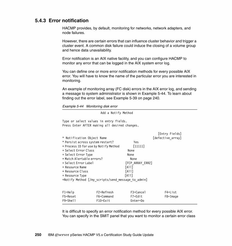
5.4.3 Error notificationHACMP provides, by default, monitoring for networks, network adapters, and node failures.
However, there are certain errors that can influence cluster behavior and trigger a cluster event. A common disk failure could induce the closing of a volume group and hence data unavailability.
Error notification is an AIX native facility, and you can configure HACMP to monitor any error that can be logged in the AIX system error log.
You can define one or more error notification methods for every possible AIX error. You will have to know the name of the particular error you are interested in monitoring.
An example of monitoring array (FC disk) errors in the AIX error log, and sending a message to system administrator is shown in Example 5-44. To learn about finding out the error label, see Example 5-39 on page 240.
Example 5-44 Monitoring disk error
Add a Notify Method
Type or select values in entry fields.Press Enter AFTER making all desired changes.
[Entry Fields]* Notification Object Name [defective_array]* Persist across system restart? Yes + Process ID for use by Notify Method [11111] + Select Error Class None + Select Error Type None + Match Alertable errors? None + Select Error Label [FCP_ARRAY_ERR2] + Resource Name [All] + Resource Class [All] + Resource Type [All] +Notify Method [/my_scripts/send_message_to_admin]
F1=Help F2=Refresh F3=Cancel F4=ListF5=Reset F6=Command F7=Edit F8=ImageF9=Shell F10=Exit Enter=Do
It is difficult to specify an error notification method for every possible AIX error. You can specify in the SMIT panel that you want to monitor a certain error class
250 IBM Eserver pSeries HACMP V5.x Certification Study Guide Update
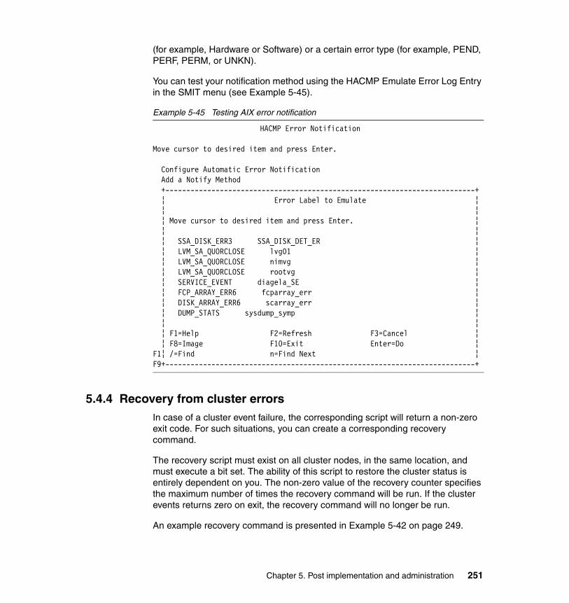
(for example, Hardware or Software) or a certain error type (for example, PEND, PERF, PERM, or UNKN).
You can test your notification method using the HACMP Emulate Error Log Entry in the SMIT menu (see Example 5-45).
Example 5-45 Testing AIX error notification
HACMP Error Notification
Move cursor to desired item and press Enter.
Configure Automatic Error Notification Add a Notify Method +--------------------------------------------------------------------------+ ¦ Error Label to Emulate ¦ ¦ ¦ ¦ Move cursor to desired item and press Enter. ¦ ¦ ¦ ¦ SSA_DISK_ERR3 SSA_DISK_DET_ER ¦ ¦ LVM_SA_QUORCLOSE lvg01 ¦ ¦ LVM_SA_QUORCLOSE nimvg ¦ ¦ LVM_SA_QUORCLOSE rootvg ¦ ¦ SERVICE_EVENT diagela_SE ¦ ¦ FCP_ARRAY_ERR6 fcparray_err ¦ ¦ DISK_ARRAY_ERR6 scarray_err ¦ ¦ DUMP_STATS sysdump_symp ¦ ¦ ¦ ¦ F1=Help F2=Refresh F3=Cancel ¦ ¦ F8=Image F10=Exit Enter=Do ¦F1¦ /=Find n=Find Next ¦F9+--------------------------------------------------------------------------+
5.4.4 Recovery from cluster errorsIn case of a cluster event failure, the corresponding script will return a non-zero exit code. For such situations, you can create a corresponding recovery command.
The recovery script must exist on all cluster nodes, in the same location, and must execute a bit set. The ability of this script to restore the cluster status is entirely dependent on you. The non-zero value of the recovery counter specifies the maximum number of times the recovery command will be run. If the cluster events returns zero on exit, the recovery command will no longer be run.
An example recovery command is presented in Example 5-42 on page 249.
Chapter 5. Post implementation and administration 251
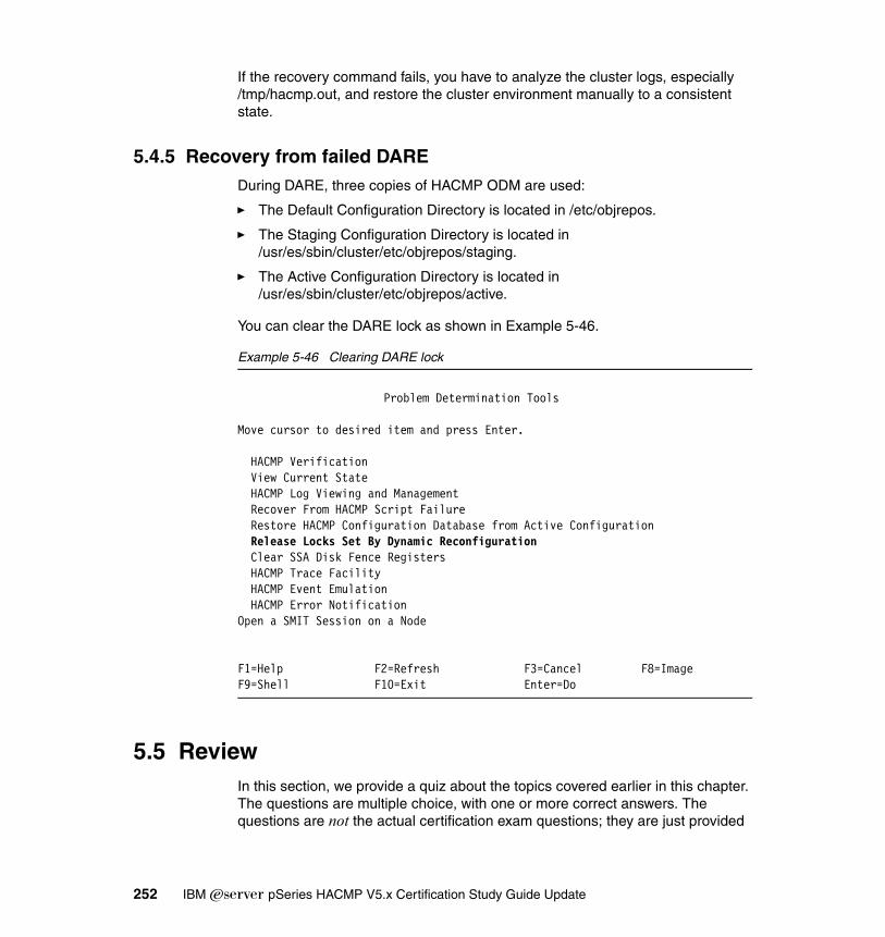
If the recovery command fails, you have to analyze the cluster logs, especially /tmp/hacmp.out, and restore the cluster environment manually to a consistent state.
5.4.5 Recovery from failed DAREDuring DARE, three copies of HACMP ODM are used:
� The Default Configuration Directory is located in /etc/objrepos.
� The Staging Configuration Directory is located in /usr/es/sbin/cluster/etc/objrepos/staging.
� The Active Configuration Directory is located in /usr/es/sbin/cluster/etc/objrepos/active.
You can clear the DARE lock as shown in Example 5-46.
Example 5-46 Clearing DARE lock
Problem Determination Tools
Move cursor to desired item and press Enter.
HACMP Verification View Current State HACMP Log Viewing and Management Recover From HACMP Script Failure Restore HACMP Configuration Database from Active Configuration Release Locks Set By Dynamic Reconfiguration Clear SSA Disk Fence Registers HACMP Trace Facility HACMP Event Emulation HACMP Error NotificationOpen a SMIT Session on a Node
F1=Help F2=Refresh F3=Cancel F8=ImageF9=Shell F10=Exit Enter=Do
5.5 ReviewIn this section, we provide a quiz about the topics covered earlier in this chapter. The questions are multiple choice, with one or more correct answers. The questions are not the actual certification exam questions; they are just provided
252 IBM Eserver pSeries HACMP V5.x Certification Study Guide Update
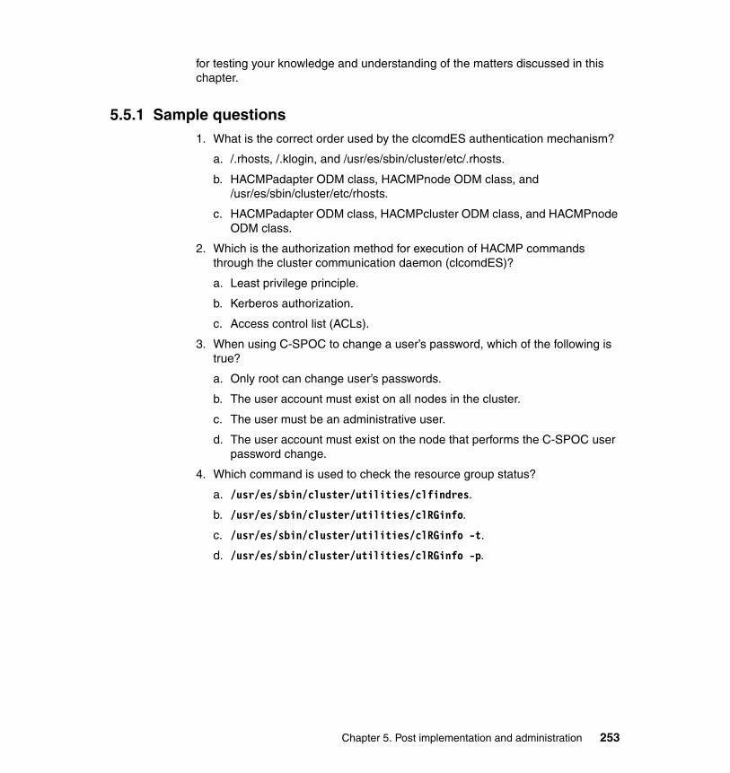
for testing your knowledge and understanding of the matters discussed in this chapter.
5.5.1 Sample questions1. What is the correct order used by the clcomdES authentication mechanism?
a. /.rhosts, /.klogin, and /usr/es/sbin/cluster/etc/.rhosts.
b. HACMPadapter ODM class, HACMPnode ODM class, and /usr/es/sbin/cluster/etc/rhosts.
c. HACMPadapter ODM class, HACMPcluster ODM class, and HACMPnode ODM class.
2. Which is the authorization method for execution of HACMP commands through the cluster communication daemon (clcomdES)?
a. Least privilege principle.
b. Kerberos authorization.
c. Access control list (ACLs).
3. When using C-SPOC to change a user’s password, which of the following is true?
a. Only root can change user’s passwords.
b. The user account must exist on all nodes in the cluster.
c. The user must be an administrative user.
d. The user account must exist on the node that performs the C-SPOC user password change.
4. Which command is used to check the resource group status?
a. /usr/es/sbin/cluster/utilities/clfindres.
b. /usr/es/sbin/cluster/utilities/clRGinfo.
c. /usr/es/sbin/cluster/utilities/clRGinfo -t.
d. /usr/es/sbin/cluster/utilities/clRGinfo -p.
Chapter 5. Post implementation and administration 253

5. What is the SMIT fast path for performing maintenance activity in a live HACMP cluster (C-SPOC)?
a. smitty clstart.
b. smitty cspoc.
c. smitty cl_admin.
6. The STICKY resource group attribute used in earlier versions of HACMP is replaced by which new attribute of HACMP V5.x?
a. Priority preferred location.
b. Persistent resource location.
c. Priority override location.
d. Dynamic node priority.
7. To move a resource group from one node to another, which event should be used in HACMP V5.x?
a. rg_migrate.
b. cldare -M.
c. move_rg.
d. rg_move.
8. When moving a resource group to a lower priority node, which parameter should be set to true to activate the resource group on the same node after a cluster reboot?
a. Persist across cluster reboot.
b. Priority override location.
c. Cascading without fallback.
d. Dynamic node priority.
9. Which file should be checked to verify the priority override location (POL) settings?
a. /var/hacmp/clverify/clverify.log.
b. /usr/es/sbin/cluster/etc/clpol.
c. /tmp/hacmp.out.
d. /var/hacmp/clpol.
254 IBM Eserver pSeries HACMP V5.x Certification Study Guide Update
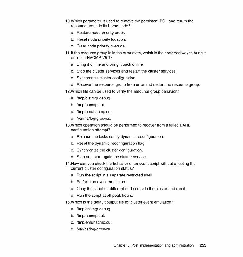
10.Which parameter is used to remove the persistent POL and return the resource group to its home node?
a. Restore node priority order.
b. Reset node priority location.
c. Clear node priority override.
11.If the resource group is in the error state, which is the preferred way to bring it online in HACMP V5.1?
a. Bring it offline and bring it back online.
b. Stop the cluster services and restart the cluster services.
c. Synchronize cluster configuration.
d. Recover the resource group from error and restart the resource group.
12.Which file can be used to verify the resource group behavior?
a. /tmp/clstmgr.debug.
b. /tmp/hacmp.out.
c. /tmp/emuhacmp.out.
d. /var/ha/log/grpsvcs.
13.Which operation should be performed to recover from a failed DARE configuration attempt?
a. Release the locks set by dynamic reconfiguration.
b. Reset the dynamic reconfiguration flag.
c. Synchronize the cluster configuration.
d. Stop and start again the cluster service.
14.How can you check the behavior of an event script without affecting the current cluster configuration status?
a. Run the script in a separate restricted shell.
b. Perform an event emulation.
c. Copy the script on different node outside the cluster and run it.
d. Run the script at off peak hours.
15.Which is the default output file for cluster event emulation?
a. /tmp/clstmgr.debug.
b. /tmp/hacmp.out.
c. /tmp/emuhacmp.out.
d. /var/ha/log/grpsvcs.
Chapter 5. Post implementation and administration 255

16.Which files should be checked for deadman switch occurrence?
a. /usr/es/adm/cluster.log and /tmp/dms_loads.out.
b. /usr/es/adm/cluster.log and /tmp/clstmgr.debug.
c. /tmp/emuhacmp.out and /var/ha/logs/rsct.log.
d. /var/adm/ras/dms.out and /tmp/dms_loads.out.
17.What is the default directory used to store the C-SPOC log files?
a. /usr/es/adm.
b. /usr/es/sbin/cluster/history.
c. /var/ha.
d. /tmp.
18.Which command should be used to generate a cluster snapshot?
a. /usr/es/sbin/cluster/utilities/clsnapshot.
b. snap -e.
c. mkszfile.
d. /usr/es/sbin/cluster/utilites/clsnap.
19.What is the maximum number of service IP labels/addresses that can be used in a HACMP V5.x cluster?
a. 64.
b. 128.
c. 256.
d. 512.
Answers to the quiz can be found in Appendix A, “ITSO sample cluster” on page 285.
256 IBM Eserver pSeries HACMP V5.x Certification Study Guide Update
Chapter 6. HACMP V5.2 and V5.3
This chapter provides information about HACMP V5.2 and 5.3. It is intended as an introduction to the latest functionality provided in HACMP V5.2 and V5.3. At the time that this material was developed (July - August 2005), the certification exam covered these new topics only partially, but an updated exam is under development. This new functionality is presented for your reference.
6
© Copyright IBM Corp. 2004, 2006. All rights reserved. 257
6.1 OverviewHACMP V5.2 has new features and functionality that cover a wide spectrum of HACMP topics. These features include both usability and performance, and also interoperability and integration with other IBM products.
HACMP V5.3 includes all the features of HACMP V5.2 and HACMP 5.1. It also takes advantage more efficiently of the Reliable Scalable Cluster Technology (RSCT) for HACMP clusters with both non-concurrent and concurrent access.
6.2 Features and changes in V5.2Some of the most important new features are:
� Two node configuration assistant.
Cluster setup for a two node configuration in five simple steps.
� Automated test tool.
An automated test procedure that simplifies the testing of a cluster during the implementation phase, and later for periodic cluster validation.
� Custom only resource groups and RG distribution (local and between sites).
The classic RG types are not used anymore. Also, HACMP provides policy based resource group distribution for better cluster resource usage.
� Cluster configuration auto correction.
This tool provides auto correction of cluster configuration errors during cluster verification.
� Cluster file collections.
For maintaining a sane cluster, certain files need to be synchronized among all nodes in the cluster.
� Automatic cluster verification.
Provides automatic cluster verification every 24 hours. Sends messages about un-synchronized cluster changes (which may affect cluster reaction in a takeover situation).
� Web-based SMIT management.
Provides HACMP SMIT menus and cluster status integration with a Web server. Allows cluster configuration via a Web browser.
258 IBM Eserver pSeries HACMP V5.x Certification Study Guide Update

� Resource group dependencies.
In a multi-tier application environment, the HACMP RGs should be started in a specific sequence, or recycled every time a resource group is moved due to a takeover operation.
� Application startup monitoring and multiple application monitors.
Beside the “classic” application monitoring, an application can be also monitored during the startup process. This is useful when configuring RG dependencies.
It is also possible to configure multiple application monitors for each application server.
� Enhanced online planning worksheets.
The new OLPWs can now read the configuration from an existing HACMP cluster.
� User password management.
Users can change their own password on all or some of the cluster nodes (In HACMP V5.1, only root could change another user’s password).
� HACMP Smart Assist for WebSphere® Application Server (SAW).
Integration scripts for providing high availability in a WebSphere Application Server environment.
� New security features.
Cluster communication daemon message authentication (based on RSCT ctsec security).
� Dynamic LPARs support.
Integration of HACMP with Hardware Management Console for moving CPU and memory resources between LPARs in a takeover situation.
� CUoD support.
Resource (CPU) activation from the Capacity Upgrade on Demand (CUoD) pool on takeover node.
� Cluster lock manager dropped.
Cluster lock manager support has been dropped due to the usage of enhanced concurrent mode volume groups (ECM).
� Cross-site LVM mirroring.
Complete automation of AIX LVM mirroring via SAN between two sites.
Chapter 6. HACMP V5.2 and V5.3 259
� Resource Monitoring and Control (RMC) subsystem replaces Event Management (EM).
This feature is mostly transparent to the users and provides faster and more accurate calculation of available node resources for fallover using Dynamic Node Priority (DNP).
� HACMP integration with Enterprise Remote Copy Management Facility (eRCMF).
This feature provides complete automated fallover and reintegration between sites in a ESS with an eRCMF environment.
6.3 New features in HACMP 5.3In addition to Smart Assist for WebSphere, HACMP 5.3 provides new Smart Assist features:
– DB2® 8.1, 8.2 EE– Oracle Application Server 10g (OAS)
Additional resource and resource group management features include:
– Cluster-wide resource group location dependencies (including XD)– Distribution preference for the IP service aliases
Online Planning Worksheet functionality has been extended, and also the OLPW configuration file format has been unified. In this version, it is possible to:
– Clone a cluster from an existing “live” configuration– Extracting Cluster snapshot information to XML format for use with OLPW
OEM volume groups and file systems has been added to for Veritas Volume Manager (VxVM), and Veritas File System (VxFS).
It is also possible to generate and send SMS pager messages (e-mail format) when HACMP events occur.
Performance and usability have been improved using new architecture for communication between Clinfo and the Cluster Manager.
Using Cluster Information (Clinfo) API versioning removes requirement to recompile clients in the future.
Cluster Verification facilities continue to grow to help customers prevent problems before they occur.
260 IBM Eserver pSeries HACMP V5.x Certification Study Guide Update

6.3.1 Migration to HACMP V5.3 issues
If you are upgrading from a pre-5.2 release– Manual reconfiguration of User-Defined Events is required. HACMP 5.2
and 5.3 interact with the RSCT Resource Monitoring and Control (RMC) subsystem instead of the Event Management subsystem.
– The Cluster Lock Manager (cllockd or cllockdES) is no longer supported as of HACMP 5.2. During node-by-node migration, it is uninstalled. Installing HACMP 5.2 or 5.3 removes the Lock Manager binaries and definitions.
– In order to improve HACMP security, all HACMP ODMs will be owned by root, group hacmp. Group "hacmp" is created if it does not already exist.
– HACMPdisksubsys has permissions of 0600; all the other HACMP ODMs have permissions of 0640.
If you are upgrading from a pre-5.3 release– Clinfo and libcl source no longer shipped.
– cluster.adt.es.client.samples.clinfo and cluster.adt.es.client.samples.libcl.
– A README is shipped suggesting customers contact [email protected] if source code is needed.
– Applications using the pre-5.2 Clinfo API must be recompiled.
– Applications using registerwithclsmuxpd() must recompile.
– Recompilation recommended in any case.
– A new license agreement is included in this release. All installations and migrations must accept the new license.
– The clsmuxpd daemon no longer exists as a standalone daemon in HACMP 5.3.
– The command line utilities cldiag and clverify are removed. All functionality is available from SMIT in HACMP 5.3.
– The Network-based Distribution Policy for resource groups is removed. Migration updates Resource Groups to use Node-based distribution.
– All HACMP binaries intended for use by non-root users have 2555 permissions (i.e., readable and executable by all users, with the setgid bit turned on so that the program runs as group “hacmp”).
– As of HACMP 5.3, a GID has been reserved for “hacmp”, which simplifies packaging and should eliminate the TCB problems reported in HA 5.2.
Chapter 6. HACMP V5.2 and V5.3 261
6.3.2 Additional improvementsImprovements in management, configuration simplification, automation, and performance include:
– Cluster verification at cluster startup– Additional corrective actions taken during verification– clverify warns of recognizable single points of failure– clverify integrates HACMP/XD options - PPRC; GeoRM; GLVM– clverify automatically populates the clhosts file– Further integration of HACMP with RSCT– Removal of certain site related restrictions from HACMP– Location dependency added for Resource Groups
WebSMIT security improved by:
– Client data validation before any HACMP commands are executed– Server side validation of parameters– WebSMIT authentication tools integrated with the AIX authentication
mechanisms
Cluster manager (clstrmgrES) daemon is running at all times (regardless of cluster status - up or down) to support further automation of cluster configuration and enhanced administration. Also, cluster multi-peer extension daemon (clsmuxpdES) and cluster information daemon (clinfoES) shared memory was removed.
6.3.3 Two node configuration assistantThe two node configuration assistant is a configuration tool that simplifies the integration in HACMP of a single application previously running on a stand-alone system. This tool provides an easy and fast way of configuring a high availability solution for an existing application by simply adding a node to the environment and connecting the networks and storage. The cluster that is created by this assistant contains:
� A single resource group configured to:
– Come online on the local node at cluster start
– To fall over to the remote takeover node if the local node fails
– To remain on the remote takeover node when the local node rejoins the cluster
� This tool can be used via:
– SMIT
– WebSMIT
262 IBM Eserver pSeries HACMP V5.x Certification Study Guide Update

– The clconfigassist utility, which is in fact a Java-based “wizard” interface.
The /usr/es/sbin/cluster/clconfigassist directory contains the script and the Java package needed to launch the two-node configuration assistant. Java must be available via the PATH (PATH=/usr/java131/jre/bin:...).
6.3.4 Automated test toolThe Cluster Test Tool reduces implementation costs by simplifying the validation of cluster functionality.
It reduces support costs by automating the testing of an HACMP cluster to ensure correct behavior in the event of a real cluster failure.
The Cluster Test Tool executes a test plan, which consists of a series of individual tests. Tests are carried out in sequence and the results are analyzed by the test tool.
Administrators may define a custom test plan or use the automated test procedure.
The test results and other important data are collected in the test tool's log file. Additional information about the tests carried out during the automated test procedure can be retrieved from the HACMP logs (hacmp.out, cluster.log, and so on).
The Cluster Test Tool is designed to test the user's configuration during cluster implementation or for periodic cluster validation. The Cluster Test Tool is not designed to verify the correct operation of the Cluster Manager.
The basic criteria for the success of any test is whether or not the resources are still available. Success and failure of the tests is judged based on the following types of questions:
� Are the nodes in the expected state?� Are the resource groups still available?� Did HACMP respond to the failure?
Note: There are cases where HACMP's behavior is correct, but the test will be judged to have failed.
For example, forcing a node down will fail, if it contains a resource group using fast disk takeover option. This is normal, since fast disk takeover uses enhanced concurrent VGs and the cluster services cannot be stopped without bringing down the RG (for varying off the concurrent VGs).
Chapter 6. HACMP V5.2 and V5.3 263

HACMP provides an “out-of-the-box” test plan, but users can also configure custom test procedures to be run by the automated test tool.
Custom tests can be configured by specifying a test plan and an optional test variables file. Using custom test procedures with variables files provides for reusing the test procedures for multiple clusters, by customizing only the variables file.
The following tests run under the control of the automated test tool:
� For cluster topology:
– NODE_UP for all nodes
– NODE_DOWN_GRACEFUL for a random node
– NODE_UP for a node that just stopped
– NODE_DOWN_TAKEOVER for a random node
– NODE_UP for a node that just stopped
– NODE_DOWN_FORCED for a random node
– NODE_UP for a node that just stopped
� For concurrent RG:
– SERVER_DOWN test on a random node for each concurrent RG with a monitored application
� For non-concurrent RG, run the following tests for each non concurrent RG with a monitored application:
– NETWORK_DOWN_LOCAL on the owner node
– NETWORK_UP_LOCAL on the same node
– SERVER_DOWN on the owner node
� For catastrophic node failure
– CLSTRMGR_KILL test for a random node
To access the cluster test tool menu, run smitty hacmp_testtool_menu (see Example 6-1).
Example 6-1 Cluster test tool
HACMP Cluster Test Tool
Move cursor to desired item and press Enter.
Execute Automated Test Procedure Execute Custom Test Procedure
264 IBM Eserver pSeries HACMP V5.x Certification Study Guide Update
F1=Help F2=Refresh F3=Cancel F8=ImageF9=Shell F10=Exit Enter=Do
The default cluster test plans are located in the /usr/es/sbin/cluster/cl_testool/ directory.
For detailed information, see the High Availability Cluster Multi-Processing for AIX Adminstration and Troubleshooting Guide, SC23-4862-03.
6.3.5 Custom (only) resource groupsStarting with HACMP V5.2, all resource groups will be defined using the custom resource group model. Existing groups (cascading, rotating, and concurrent) will be converted.
All groups are now referred to as simply resource groups. This new model provides additional flexibility when configuring HACMP resource groups, reduces implementation costs by simplifying initial configuration, and reduces support and development costs when implementing new features.
Resource groups use policies to define behavior:
� Startup: What happens when the cluster first starts?� Fallover: What happens when a failure occurs?� Fallback: What happens when a node rejoins the cluster?
This feature also supports:
� HACMP sites
� IPAT via IP replacement networks (not supported in HACMP V5.1 with custom RGs)
� Resource group distribution:
– Node distribution policy:
This is the default behavior. In this policy, no two resource groups are activated on the same node during startup, and IP Service labels are optional for these resource groups.
– Network distribution policy:
No two resource groups will be activated on the same node and on the same network during startup. A service label must be included in the resource group. Functionally the same as HACMP V5.1 rotating resource groups.
Chapter 6. HACMP V5.2 and V5.3 265

For increased availability and self healing clusters, in HACMP V5.2, a node_up event attempts to activate resource groups in the Error state (if the node which comes up is part of the resource group in the Error state).
The resource group configuration menu can be accessed by running the smitty cm_add_a_resource_group_dialog.custom fast path (see Example 6-2 on page 266).
Example 6-2 Custom resource groups only
Add a Resource Group
Type or select values in entry fields.Press Enter AFTER making all desired changes.
[Entry Fields]* Resource Group Name [rg_12]* Participating Nodes (Default Node Priority) [node1 node2 node3] +
Startup Policy Online On Home Node O> + Fallover Policy Fallover To Next Prio> + Fallback Policy Fallback To Higher Pr> +
F1=Help F2=Refresh F3=Cancel F4=ListF5=Reset F6=Command F7=Edit F8=ImageF9=Shell F10=Exit Enter=Do
6.3.6 Cluster configuration auto correctionThis tool provides auto correction of the following cluster configuration errors during cluster verification:
� HACMP Shared Volume Group Time Stamps
If the time stamps for a shared volume group are not up to date on a node, HACMP verification will drive an update of the ODM information on that node.
� Update /etc/hosts
Update /etc/hosts so that it contains entries for all the HACMP managed IP addresses.
� SSA concurrent volume groups and SSA router node numbers
If SSA concurrent volume groups are in use, set up the SSA node numbers on each node.
266 IBM Eserver pSeries HACMP V5.x Certification Study Guide Update

� Importing Volume Groups
If the disks are available, but the volume group has not been imported to the node, then import the volume group.
� Mount Points and Filesystems
If a file system has not been created on one of the cluster nodes, but the shared volume group is available, create the mount point and file system.
� Missing HACMP entries from /etc/services
If the required HACMP service entries are missing from /etc/services on any cluster node, then add the missing entries (clsmuxpd, clm_smux, topsvcs, and grpsvcs).
� Missing HACMP entries /etc/snmpd.conf and /etc/snmpd.peers
If the required HACMP snmpd entries are missing from the configuration files /etc/snmpd.peers or /etc/snmpd.conf, then add the required entries.
To access the cluster verification menu, run smitty hacmp and select Extended Configuration → Extended Verification and Synchronization (see Example 6-3).
Example 6-3 Cluster verification options
HACMP Verification and Synchronization
Type or select values in entry fields.Press Enter AFTER making all desired changes.
[Entry Fields]* Verify, Synchronize or Both [Both] +* Force synchronization if verification fails? [No] +* Verify changes only? [No] +* Logging [Standard] +
F1=Help F2=Refresh F3=Cancel F4=ListF5=Reset F6=Command F7=Edit F8=ImageF9=Shell F10=Exit Enter=Do
Restriction: HACMP takes corrective action only if cluster services are down on all cluster nodes.
Users can specify during the verification process if they want automatic, interactive, or no corrections for configuration errors discovered during cluster verification.
Chapter 6. HACMP V5.2 and V5.3 267

6.3.7 Cluster file collectionsSome configuration files need to be kept in sync on all HACMP nodes; previously, this was mostly the user’s responsibility. Among these files are:
– Application start/stop scripts– Application monitoring scripts – Pre-/post-event scripts– System configuration files
This operation was prone to user errors, since modified or corrupt files on some nodes can cause undesired results. Users needed a reliable way to automatically keep these files in sync on all cluster nodes, reducing the possibility of user error.
This feature simplifies cluster management by keeping common files consistent among cluster nodes. This procedure is completely automatic and supports all regular files. It uses the cluster communication daemon (clcomdES) for transferring files among the cluster nodes.
Files can be synchronized in three ways:
� Manually, using SMIT
� During cluster verification and synchronization
� Automatically, upon a change in the file (Verification is performed by default every 10 minutes, but the interval can be changed.)
HACMP provides two default File Collections, but users can add their own file collections. The default file collections are:
� Configuration_Files
This collection contains essential HACMP and AIX configuration files. Users can add/delete files from the collection, and can also change the propagation options (the defaults for verify/sync and auto are no)
Example files: /etc/hosts, /etc/services, /etc/inetd.conf, /usr/es/sbin/cluster/etc/rhosts, and so on.
� HACMP_Files
This collection is for all user-configurable files in HACMP, and it cannot be removed or modified. The files in this File Collection cannot be removed, modified, or added.
Users can change the propagation options (the defaults for verify/sync and auto are no). Owner execute permissions are automatically turned on.
Important: This tool is meant for typical configuration files; no special files (pipes, links, directories, and so on) are supported.
268 IBM Eserver pSeries HACMP V5.x Certification Study Guide Update

The list of files is not stored in the file collection ODMs, but is dynamically generated.
To configure HACMP file collections, run smitty cm_filecollection_menu (see Example 6-4).
Example 6-4 File collections menu
HACMP File Collection Management
Move cursor to desired item and press Enter.
Manage File Collections Manage Files in File Collections Propagate Files in File Collections
F1=Help F2=Refresh F3=Cancel F8=ImageF9=Shell F10=Exit Enter=Do
6.3.8 Automatic cluster verificationThis feature capitalizes on the improvements provided by the cluster communication daemon (clcomdES) since HACMP V5.1. Cluster verification (clver) runs every 24 hours on a selected cluster node, if the defined node is available.
The feature is activated by default after the first cluster synchronization. The node does not have to be active (Active Cluster Manager is not required); it just must have one HACMP defined communication path available.
A user can change this feature’s settings via the SMIT interface. Possible changes are:
� Enabling/disabling the feature
� The time of day (one hour interval between 00 - 23 hours) to run the feature
Cluster verification results are reported in a log file on all accessible cluster nodes. Additional reports are generated in case of detected errors.
Note: This feature should not be used together with PSSP file collections, unless you make sure there is no overlap between the two file synchronization methods.
This feature is not used for user and password management.
Chapter 6. HACMP V5.2 and V5.3 269
Provides automatic cluster verification every 24 hours. Sends messages about un-synchronized cluster changes (which may affect cluster reaction in a take-over situation).
6.3.9 Web-based SMIT managementThis feature provides HACMP SMIT menus and cluster status integration with a Web server. It also allows cluster configuration via a Web browser.
It is, in fact, a JavaScript™ based interface to SMIT, so it looks and feels familiar. The extensions also include:
� Secure communication� Tree view� Integrated clstat functions� Online documentation bookshelf®
This feature operates with an existing Apache compliant Web server, and logs messages similar to smit.log. It also provides secure access to cluster configuration menus using a different dedicated port (42267/TCP) and SSL based encryption.
6.3.10 Resource group dependenciesIn practice, a cluster provides high availability for multiple applications that may have inter-dependencies (a multi-tier application with databases, middleware, and front ends).
Complex relationships were previously implemented via custom pre- and post-event scripts and also by some special application scripts. The resulting configuration was hard to maintain and did not scale well.
The HACMP resource groups dependencies feature allows the administrator to specify cluster-wide dependencies between resource groups.
By simplifying the configuration of multi-tier application environments, the feature reduces both implementation and on-going support costs in an on-demand operating environment.
Restrictions:
Restrictions: Web-based SMIT management is available in English only, and supports HACMP panels only; no XD menus are available.
270 IBM Eserver pSeries HACMP V5.x Certification Study Guide Update
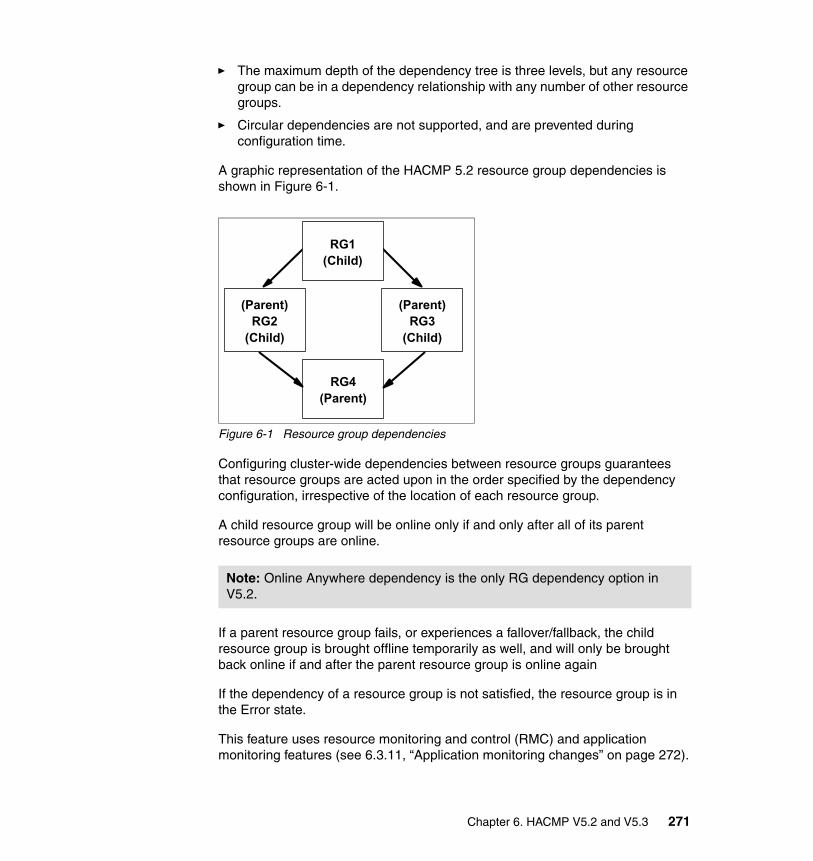
� The maximum depth of the dependency tree is three levels, but any resource group can be in a dependency relationship with any number of other resource groups.
� Circular dependencies are not supported, and are prevented during configuration time.
A graphic representation of the HACMP 5.2 resource group dependencies is shown in Figure 6-1.
Figure 6-1 Resource group dependencies
Configuring cluster-wide dependencies between resource groups guarantees that resource groups are acted upon in the order specified by the dependency configuration, irrespective of the location of each resource group.
A child resource group will be online only if and only after all of its parent resource groups are online.
If a parent resource group fails, or experiences a fallover/fallback, the child resource group is brought offline temporarily as well, and will only be brought back online if and after the parent resource group is online again
If the dependency of a resource group is not satisfied, the resource group is in the Error state.
This feature uses resource monitoring and control (RMC) and application monitoring features (see 6.3.11, “Application monitoring changes” on page 272).
Note: Online Anywhere dependency is the only RG dependency option in V5.2.
(Parent)RG3
(Child)
(Parent)RG2
(Child)
RG1(Child)
RG4(Parent)
Chapter 6. HACMP V5.2 and V5.3 271

New in HACMP V5.3New resource group dependency policies include:
� Online On Same Node Dependency
Groups can be brought online only on the node where all other resource groups from the same node dependency are currently online
� Online On Same Site Dependency
Groups can be brought online only on the site where the other resource groups from the same site dependency are currently online
� Online On Different Nodes Dependency
Groups can only be brought online on nodes not hosting a group in the dependency
When you move a resource group that belongs to this dependency, priorities are treated as of equal value. This means that you cannot use a User Requested rg_move to move a High priority resource group onto a node that already contains an Intermediate or Low priority resource group.You must first move the other resource groups manually, then move the High priority resource group
6.3.11 Application monitoring changesIn previous releases, only one application monitor could be defined for an application server and one monitored application could be defined per resource group.
Customers requested the ability to configure both a process death monitor (to immediately catch process failures) along with a custom monitor to ensure the application was doing useful work.
Also, there was no failure detection at application startup time, which means that the application server start script was invoked as a background process with no wait or error checking. In a multi-tiered environment, there was no easy way to ensure that applications of higher tiers could be started.
HACMP V5.2 supports multiple application monitors per application server, which provides support for complex configurations.
In the current release, any number of monitors can be used in any combination, up to a total of 128 (cluster wide).
Beside long running monitors for applications, monitors can also be used to monitor the startup (initialization) of the application; in this case, the monitor is called immediately after the application server start script.
272 IBM Eserver pSeries HACMP V5.x Certification Study Guide Update

The exit code from the monitor determines the application server state; it will trigger a recovery on failure.
Enhancements to Application Monitoring reduce support costs while maintaining the highest level of availability within a complex on demand environment. Application Monitoring provides for self-healing clusters.
To configure application monitoring (both application process and custom monitoring), use the smitty cladd_custom_appmon.dialog fast path (see Example 6-5).
Example 6-5 Application monitoring
Add a Custom Application Monitor
Type or select values in entry fields.Press Enter AFTER making all desired changes.
[Entry Fields]* Monitor Name []* Application Server(s) to Monitor +* Monitor Mode [Long-running monitor> +* Monitor Method [] Monitor Interval [] # +--------------------------------------------------------------------------+#* ¦ Monitor Mode ¦#* ¦ ¦# ¦ Move cursor to desired item and press Enter. ¦#* ¦ ¦ ¦ Long-running monitoring ¦ ¦ Startup Monitoring ¦ ¦ Both ¦ ¦ ¦ ¦ F1=Help F2=Refresh F3=Cancel ¦F1¦ F8=Image F10=Exit Enter=Do ¦F5¦ /=Find n=Find Next ¦F9+--------------------------------------------------------------------------+
6.3.12 Enhanced online planning worksheetsThe new online planning worksheets (OLPWs) can now read the configuration from an existing HACMP cluster (see Figure 6-2).
Note: When configuring application monitoring, it is extremely important to use the correct timers for monitoring and stabilization intervals; otherwise, application monitoring may falsely trigger application recovery, resulting in an unstable cluster.
Chapter 6. HACMP V5.2 and V5.3 273

Figure 6-2 Online planning worksheets
OLPW is, in fact, a Java utility that provides a GUI for creating an offline cluster configuration and for documenting it (in a HTML report). The utility can be run on any system (AIX, Linux, or Windows) with a graphics display and a Java run-time environment. If this utility is run on one of the cluster nodes, it can also read the existing cluster configuration.
OLPW produces a file in XML format and can also produce an HTML report. The XML file can be imported on an AIX node (with HACMP software installed) to produce a cluster configuration.
New in HACMP 5.3OLPW Worksheet – an XML file containing a cluster configuration. This file is created by OLPW and by the cl_exportdefinition utility
The cluster utility cl_opsconfig is used by OLPW to use an OLPW Worksheet file and to configure an HACMP cluster based upon the information contained in this file. This feature is also updated to accept ASCII-based cluster configuration files created by an user (see Figure 6-3).
OLPW 5.2 cluster.hawHACMPdefinition
write
readcl_exportdefinition
(new)
cl_opsconfigwrite
read
OLPW 5.2 cluster.hawHACMPdefinition
write
readcl_exportdefinition
(new)
cl_opsconfigwrite
read
Standalone system (PC) or AIX HACMP Nodes
274 IBM Eserver pSeries HACMP V5.x Certification Study Guide Update

Figure 6-3 Manipulating cluster XML configuration files
The cluster utility that creates an OLPW Worksheet file from an existing HACMP cluster is named cl_exportdefinition. This feature will update it to create the XML file from an existing cluster snapshot, as shown in Figure 6-4 and Figure 6-5.
HACMP Cluster
XML
XML
Export DefinitionFile for OLPW
HACMP Cluster
Edit configuration:OLPW or XML
editorImport definition:
cl_opsconfig
NEW
Chapter 6. HACMP V5.2 and V5.3 275
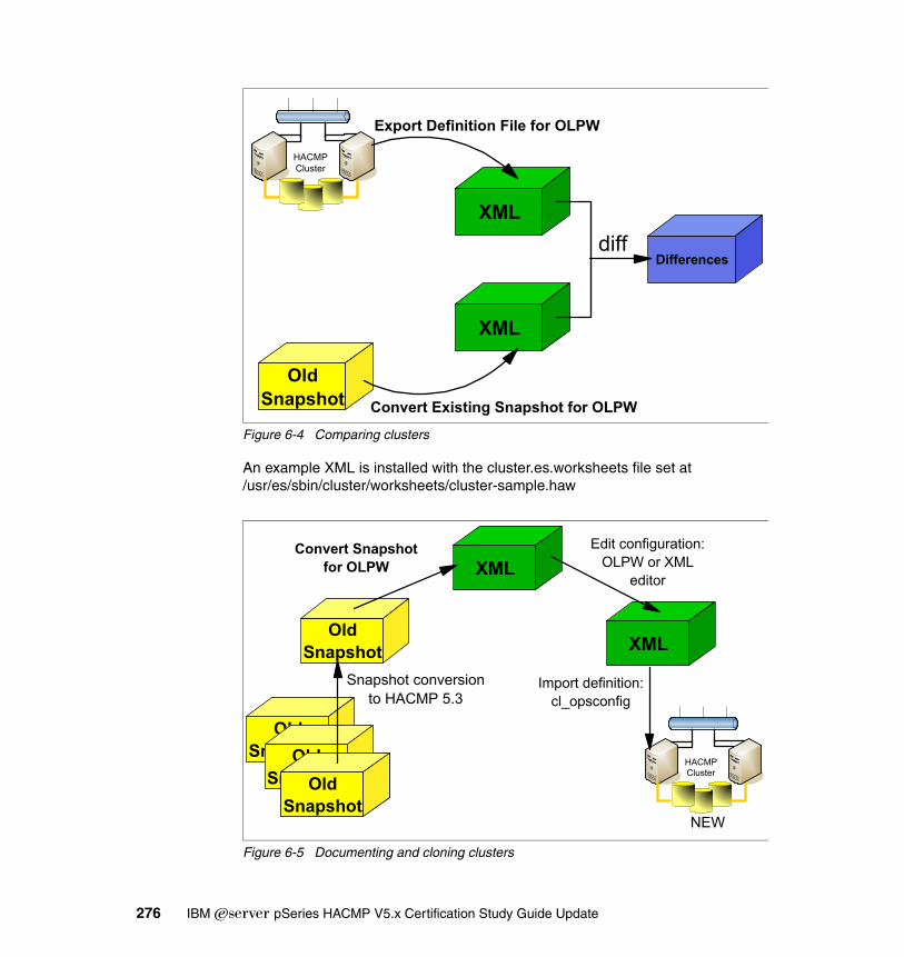
Figure 6-4 Comparing clusters
An example XML is installed with the cluster.es.worksheets file set at /usr/es/sbin/cluster/worksheets/cluster-sample.haw
Figure 6-5 Documenting and cloning clusters
HACMP Cluster
OldSnapshot
XML
Differences
XMLdiff
Export Definition File for OLPW
Convert Existing Snapshot for OLPW
OldSnapshotOld
SnapshotHACMP Cluster
OldSnapshot
XML
XML
OldSnapshot
OldSnapshot
Snapshot conversionto HACMP 5.3
Convert Snapshotfor OLPW
Edit configuration:OLPW or XML
editor
Import definition:cl_opsconfig
NEW
276 IBM Eserver pSeries HACMP V5.x Certification Study Guide Update
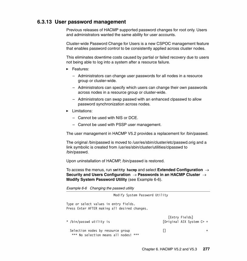
6.3.13 User password managementPrevious releases of HACMP supported password changes for root only. Users and administrators wanted the same ability for user accounts.
Cluster-wide Password Change for Users is a new CSPOC management feature that enables password control to be consistently applied across cluster nodes.
This eliminates downtime costs caused by partial or failed recovery due to users not being able to log into a system after a resource failure.
� Features:
– Administrators can change user passwords for all nodes in a resource group or cluster-wide.
– Administrators can specify which users can change their own passwords across nodes in a resource group or cluster-wide.
– Administrators can swap passwd with an enhanced clpasswd to allow password synchronization across nodes.
� Limitations:
– Cannot be used with NIS or DCE.
– Cannot be used with PSSP user management.
The user management in HACMP V5.2 provides a replacement for /bin/passwd.
The original /bin/passwd is moved to /usr/es/sbin/cluster/etc/passwd.orig and a link symbolic is created from /usr/es/sbin/cluster/utilities/clpasswd to /bin/passwd.
Upon uninstallation of HACMP, /bin/passwd is restored.
To access the menus, run smitty hacmp and select Extended Configuration → Security and Users Configuration → Passwords in an HACMP Cluster → Modify System Password Utility (see Example 6-6).
Example 6-6 Changing the passwd utility
Modify System Password Utility
Type or select values in entry fields.Press Enter AFTER making all desired changes.
[Entry Fields]* /bin/passwd utility is [Original AIX System C> +
Selection nodes by resource group [] + *** No selection means all nodes! ***
Chapter 6. HACMP V5.2 and V5.3 277
F1=Help F2=Refresh F3=Cancel F4=ListF5=Reset F6=Command F7=Edit F8=ImageF9=Shell F10=Exit Enter=Do
6.3.14 HACMP Smart Assist for WebSphere Application Server (SAW)Using HACMP Smart Assist for WebSphere Application Server greatly simplifies the configuration of HACMP for enterprise applications.
HACMP Smart Assist for WebSphere Application Server installs application start and stop scripts as well as monitors to make the applications highly available.
Log files, clhaws_snap, and simple uninstall routines ease the troubleshooting of HACMP Smart Assist for WebSphere Application Server.
Basic knowledge of all WebSphere Application Server components is required to provide cluster integration.
For detailed product information, see the High Availability Cluster Multi-Processing for AIX HACMP Smart Assist for WebSphere User’s Guide Version 5.2, SC23-4877.
6.3.15 New security featuresHACMP is the first IBM software to use the security infrastructure provided by RSCT.
In HACMP V5.1, the cluster communication security relied on authenticating incoming connections based on IP addresses listed in the HACMP ODM classes and in the /usr/es/sbin/cluster/etc/rhosts file. Once authentication was successful, all internode messages were sent via clcomdES in clear, un-encrypted text.
In HACMP V5.2, a new security option has been added: message authentication.
Note: If, during cluster maintenance, the cluster password utility has been updated, make sure you manually re-create the link.
Note: This product is also available for HACMP V5.1 and requires a separate license.
278 IBM Eserver pSeries HACMP V5.x Certification Study Guide Update
This is user configurable via a SMIT interface, and uses RSCT ctsec generated session keys to authenticate messages (not just connections) sent between the nodes.
In order to improve security, all HACMP ODMs will be owned by root and group hacmp. The “hacmp” group is created at install time (if it is not already there). The HACMPdisksubsystem ODM class has 0600 permission; all other ODMs have 0640.
All HACMP binaries intended for use by non-root users have 2555 permissions (that is, readable and executable by all users, with the setgid bit turned on so that the program runs as group hacmp).
If you are using the PSSP File Collections facility to maintain the consistency of /etc/group, the new group “hacmp” that is created at installation time on the individual cluster nodes may be lost when the next file synchronization occurs.
Do one of the following before upgrade or install:
� Turn off PSSP File Collections synchronization of /etc/group.
� Ensure “hacmp” is included in the master /etc/group file and ensure the change is propagated on all nodes.
For more information about RSCT security, see the IBM Reliable Scalable Cluster Technology Administration Guide, SA22-7889 and An Introduction to Security in a CSM 1.3 for AIX 5L Environment, SG24-6873.
For more information about configuring HACMP security, see the High Availability Cluster Multi-Processing for AIX Adminstration and Troubleshooting Guide, SC23-4862-03.
6.3.16 Dynamic LPARs support and CUoD supportRecent pSeries hardware is Dynamic Logical Partition (DLPAR) capable: CPU and memory resources can be added/removed without restarting AIX. Also, the Capacity Upgrade on Demand feature allow for an “pay as you grow” model.
The dynamic LPAR provides for Automatic On Demand support for HACMP managed Application Servers, and also combines the benefits of CUoD with high-availability integration.
HACMP actively manages the DLPAR and CoD resources, ensuring that cluster applications continue to have the necessary resources to run effectively after fallover.
Chapter 6. HACMP V5.2 and V5.3 279
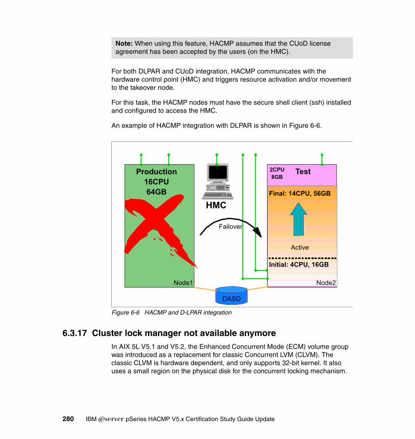
For both DLPAR and CUoD integration, HACMP communicates with the hardware control point (HMC) and triggers resource activation and/or movement to the takeover node.
For this task, the HACMP nodes must have the secure shell client (ssh) installed and configured to access the HMC.
An example of HACMP integration with DLPAR is shown in Figure 6-6.
Figure 6-6 HACMP and D-LPAR integration
6.3.17 Cluster lock manager not available anymoreIn AIX 5L V5.1 and V5.2, the Enhanced Concurrent Mode (ECM) volume group was introduced as a replacement for classic Concurrent LVM (CLVM). The classic CLVM is hardware dependent, and only supports 32-bit kernel. It also uses a small region on the physical disk for the concurrent locking mechanism.
Note: When using this feature, HACMP assumes that the CUoD license agreement has been accepted by the users (on the HMC).
Active
Production16CPU64GB
Node1
Active
Node2
Test
Final: 14CPU, 56GB
DASD
HMC
2CPU8GB
Failover
Initial: 4CPU, 16GB
280 IBM Eserver pSeries HACMP V5.x Certification Study Guide Update
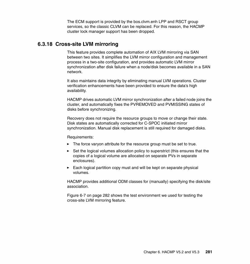
The ECM support is provided by the bos.clvm.enh LPP and RSCT group services, so the classic CLVM can be replaced. For this reason, the HACMP cluster lock manager support has been dropped.
6.3.18 Cross-site LVM mirroringThis feature provides complete automation of AIX LVM mirroring via SAN between two sites. It simplifies the LVM mirror configuration and management process in a two-site configuration, and provides automatic LVM mirror synchronization after disk failure when a node/disk becomes available in a SAN network.
It also maintains data integrity by eliminating manual LVM operations. Cluster verification enhancements have been provided to ensure the data’s high availability.
HACMP drives automatic LVM mirror synchronization after a failed node joins the cluster, and automatically fixes the PVREMOVED and PVMISSING states of disks before synchronizing.
Recovery does not require the resource groups to move or change their state. Disk states are automatically corrected for C-SPOC initiated mirror synchronization. Manual disk replacement is still required for damaged disks.
Requirements:
� The force varyon attribute for the resource group must be set to true.
� Set the logical volumes allocation policy to superstrict (this ensures that the copies of a logical volume are allocated on separate PVs in separate enclosures).
� Each logical partition copy must and will be kept on separate physical volumes.
HACMP provides additional ODM classes for (manually) specifying the disk/site association.
Figure 6-7 on page 282 shows the test environment we used for testing the cross-site LVM mirroring feature.
Chapter 6. HACMP V5.2 and V5.3 281

Figure 6-7 LVM cross-site mirroring via SAN
6.3.19 RMC replaces Event Management (EM)In previous HACMP (ES) versions, the cluster manager retrieved information for application monitoring and for dynamic node priority calculation from the Event Management (EM) layer of RSCT using the EM API.
Whenever a cluster event required information from EM, a request from the cluster manager (clstrmgrES) daemon was sent to EM, and EM calculated the results on the required nodes and returned the aggregated results to the requestor.
This process was rather slow and complicated, and could also produce erroneous results. For example, if a DNP policy based on MAX_CPU_FREE had to be calculated, the request was sent to EM and EM was issuing calculations on all nodes. This was causing additional CPU load, and thus erroneous results.
By using RMC (functionally equivalent with EM, but much more efficient), the information is readily available when requested, it does not have to be calculated.
In Figure 6-8 on page 283, we present the relationship between HACMP and RSCT components. In HACMP V5.2, the EM component has been kept only for exporting the network status to Oracle 9i RAC. All other event management functionality has been migrated to RMC.
1 2 26
Physical Volumes
1 2 26
Physical Volumes
FC (SAN) Connection
Site A Site B
LVM
Mirroring (AIX)
282 IBM Eserver pSeries HACMP V5.x Certification Study Guide Update
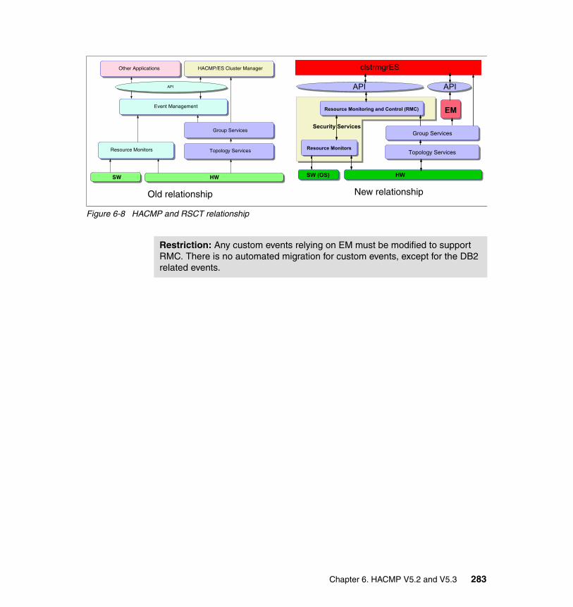
Figure 6-8 HACMP and RSCT relationship
Topology Services
SW HW
Resource Monitors
Group Services
Event Management
HACMP/ES Cluster Manager
API
Other Applications
Topology Services
Group Services
API API
clstrmgrES
SW (OS) HW
Resource Monitors
Security Services
EMResource Monitoring and Control (RMC)
Old relationship New relationship
Restriction: Any custom events relying on EM must be modified to support RMC. There is no automated migration for custom events, except for the DB2 related events.
Chapter 6. HACMP V5.2 and V5.3 283

284 IBM Eserver pSeries HACMP V5.x Certification Study Guide Update
Appendix A. ITSO sample cluster
This appendix describes the hardware and software environment used in the ITSO lab while developing this redbook. The cluster sample is provided for reference only.
A
© Copyright IBM Corp. 2004, 2006. All rights reserved. 285
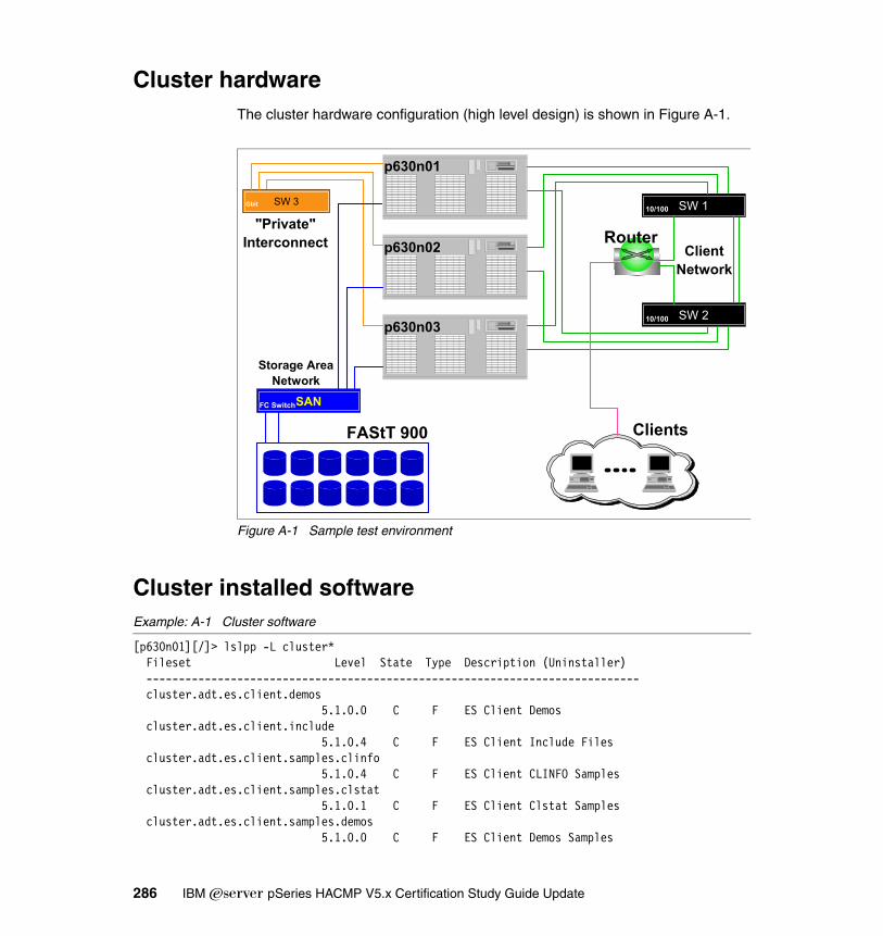
Cluster hardwareThe cluster hardware configuration (high level design) is shown in Figure A-1.
Figure A-1 Sample test environment
Cluster installed softwareExample: A-1 Cluster software
[p630n01][/]> lslpp -L cluster* Fileset Level State Type Description (Uninstaller) ---------------------------------------------------------------------------- cluster.adt.es.client.demos 5.1.0.0 C F ES Client Demos cluster.adt.es.client.include 5.1.0.4 C F ES Client Include Files cluster.adt.es.client.samples.clinfo 5.1.0.4 C F ES Client CLINFO Samples cluster.adt.es.client.samples.clstat 5.1.0.1 C F ES Client Clstat Samples cluster.adt.es.client.samples.demos 5.1.0.0 C F ES Client Demos Samples
SW 1
SW 210/100
10/100SW 3Gbit
SANFC Switch
FAStT 900 Clients
Router"Private"
Interconnect
p630n01
p630n02
p630n03
Storage AreaNetwork
ClientNetwork
286 IBM Eserver pSeries HACMP V5.x Certification Study Guide Update

cluster.adt.es.client.samples.libcl 5.1.0.2 C F ES Client LIBCL Samples cluster.adt.es.java.demo.monitor 5.1.0.0 C F ES Web Based Monitor Demo cluster.adt.es.server.demos 5.1.0.0 C F ES Server Demos cluster.adt.es.server.samples.demos 5.1.0.1 C F ES Server Sample Demos cluster.adt.es.server.samples.images 5.1.0.0 C F ES Server Sample Images cluster.doc.en_US.es.html 5.1.0.2 C F HAES Web-based HTML Documentation - U.S. English cluster.doc.en_US.es.pdf 5.1.0.2 C F HAES PDF Documentation - U.S. English cluster.es.cfs.rte 5.1.0.2 C F ES Cluster File System Support cluster.es.client.lib 5.1.0.5 C F ES Client Libraries cluster.es.client.rte 5.1.0.3 C F ES Client Runtime cluster.es.client.utils 5.1.0.4 C F ES Client Utilities cluster.es.clvm.rte 5.1.0.0 C F ES for AIX Concurrent Access cluster.es.cspoc.cmds 5.1.0.5 C F ES CSPOC Commands cluster.es.cspoc.dsh 5.1.0.0 C F ES CSPOC dsh cluster.es.cspoc.rte 5.1.0.5 C F ES CSPOC Runtime Commands cluster.es.server.diag 5.1.0.4 C F ES Server Diags cluster.es.server.events 5.1.0.5 C F ES Server Events cluster.es.server.rte 5.1.0.5 C F ES Base Server Runtime cluster.es.server.utils 5.1.0.5 C F ES Server Utilities cluster.es.worksheets 5.1.0.5 A F Online Planning Worksheets cluster.license 5.1.0.0 C F HACMP Electronic License cluster.man.en_US.es.data 5.1.0.4 C F ES Man Pages - U.S. English
Additional software installed on the nodes include the RSCT packages and the AIX enhanced concurrent logical volume manager (see Example A-2).
Example: A-2 AIX level and additional software
[p630n01][/]> oslevel -r5200-02[p630n01][/]> lslpp -L bos.clvm* Fileset Level State Type Description (Uninstaller) ---------------------------------------------------------------------------- bos.clvm.enh 5.2.0.13 C F Enhanced Concurrent Logical Volume Manager[p630n01][/]> lslpp -L rsct* Fileset Level State Type Description (Uninstaller) ---------------------------------------------------------------------------- rsct.basic.hacmp 2.3.3.0 C F RSCT Basic Function (HACMP/ES Support) rsct.basic.rte 2.3.3.0 C F RSCT Basic Function rsct.basic.sp 2.3.3.0 C F RSCT Basic Function (PSSP
Appendix A. ITSO sample cluster 287

Support) rsct.compat.basic.hacmp 2.3.3.0 C F RSCT Event Management Basic Function (HACMP/ES Support) rsct.compat.basic.rte 2.3.3.0 C F RSCT Event Management Basic Function rsct.compat.basic.sp 2.3.3.0 C F RSCT Event Management Basic Function (PSSP Support) rsct.compat.clients.hacmp 2.3.3.0 C F RSCT Event Management Client Function (HACMP/ES Support) rsct.compat.clients.rte 2.3.3.0 C F RSCT Event Management Client Function rsct.compat.clients.sp 2.3.3.0 C F RSCT Event Management Client Function (PSSP Support) rsct.core.auditrm 2.3.3.0 C F RSCT Audit Log Resource Manager rsct.core.errm 2.3.3.0 C F RSCT Event Response Resource Manager rsct.core.fsrm 2.3.3.0 C F RSCT File System Resource Manager rsct.core.gui 2.3.3.0 C F RSCT Graphical User Interface rsct.core.hostrm 2.3.3.0 C F RSCT Host Resource Manager rsct.core.rmc 2.3.3.0 C F RSCT Resource Monitoring and Control rsct.core.sec 2.3.3.0 C F RSCT Security rsct.core.sensorrm 2.3.3.0 C F RSCT Sensor Resource Manager rsct.core.sr 2.3.3.0 C F RSCT Registry rsct.core.utils 2.3.3.0 C F RSCT Utilities rsct.msg.EN_US.basic.rte 2.3.0.0 C F RSCT Basic Msgs - U.S. English (UTF) rsct.msg.EN_US.core.auditrm 2.3.0.0 C F RSCT Audit Log RM Msgs - U.S. English (UTF) rsct.msg.EN_US.core.errm 2.3.0.0 C F RSCT Event Response RM Msgs - U.S. English (UTF) rsct.msg.EN_US.core.fsrm 2.3.0.0 C F RSCT File System RM Msgs - U.S. English (UTF) rsct.msg.EN_US.core.gui 2.3.0.0 C F RSCT GUI Msgs - U.S. English (UTF) rsct.msg.EN_US.core.hostrm 2.3.0.0 C F RSCT Host RM Msgs - U.S. English (UTF) rsct.msg.EN_US.core.rmc 2.3.0.0 C F RSCT RMC Msgs - U.S. English (UTF) rsct.msg.EN_US.core.sec 2.3.0.0 C F RSCT Security Msgs - U.S. English (UTF) rsct.msg.EN_US.core.sensorrm 2.3.0.0 C F RSCT Sensor RM Msgs - U.S. English (UTF) rsct.msg.EN_US.core.sr 2.3.0.0 C F RSCT Registry Msgs - U.S.
288 IBM Eserver pSeries HACMP V5.x Certification Study Guide Update

English (UTF) rsct.msg.EN_US.core.utils 2.3.0.0 C F RSCT Utilities Msgs - U.S. English (UTF) rsct.msg.en_US.basic.rte 2.3.0.0 C F RSCT Basic Msgs - U.S. English rsct.msg.en_US.core.auditrm 2.3.0.0 C F RSCT Audit Log RM Msgs - U.S. English rsct.msg.en_US.core.errm 2.3.0.0 C F RSCT Event Response RM Msgs - U.S. English rsct.msg.en_US.core.fsrm 2.3.0.0 C F RSCT File System RM Msgs - U.S. English rsct.msg.en_US.core.gui 2.3.0.0 C F RSCT GUI Msgs - U.S. English rsct.msg.en_US.core.gui.com 2.3.0.0 C F RSCT GUI JAVA Msgs - U.S. English rsct.msg.en_US.core.hostrm 2.3.0.0 C F RSCT Host RM Msgs - U.S. English rsct.msg.en_US.core.rmc 2.3.0.0 C F RSCT RMC Msgs - U.S. English rsct.msg.en_US.core.rmc.com 2.3.0.0 C F RSCT RMC JAVA Msgs - U.S. English rsct.msg.en_US.core.sec 2.3.0.0 C F RSCT Security Msgs - U.S. English rsct.msg.en_US.core.sensorrm 2.3.0.0 C F RSCT Sensor RM Msgs - U.S. English rsct.msg.en_US.core.sr 2.3.0.0 C F RSCT Registry Msgs - U.S. English rsct.msg.en_US.core.utils 2.3.0.0 C F RSCT Utilities Msgs - U.S. English
To verify the cluster services, use the lsha alias defined in /.profile (see Example A-3).
Example: A-3 Sample /.profile file
[p630n01][/]> cat /.profileexport PS1="[`hostname -s`]["'$PWD]> 'export PATH=$PATH:/opt/csm/bin:/opt/csm/lib:/usr/sbin/rsct/bin:/opt/csm/csmbin:/usr/lpp/mmfs/binexport MANPATH=$MANPATH:/opt/freeware/man:/usr/share/man:/usr/lpp/mmfs/gpfsdocs/man/lc:/opt/csm/manexport DSH_REMOTE_CMD=/usr/bin/sshexport WCOLL=/clu52export EDITOR=vialias lsha='lssrc -a|egrep "svcs|ES"'#The following line is added by License Use Management installationexport PATH=$PATH:/usr/opt/ifor/ls/os/aix/bin
Appendix A. ITSO sample cluster 289
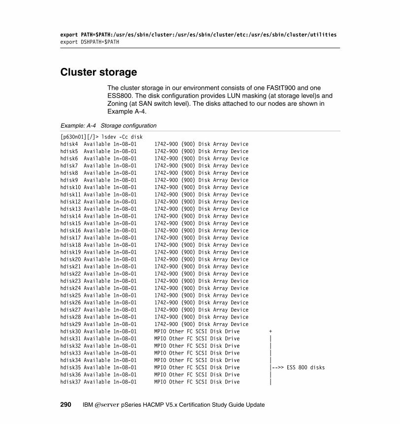
export PATH=$PATH:/usr/es/sbin/cluster:/usr/es/sbin/cluster/etc:/usr/es/sbin/cluster/utilitiesexport DSHPATH=$PATH
Cluster storageThe cluster storage in our environment consists of one FAStT900 and one ESS800. The disk configuration provides LUN masking (at storage level)s and Zoning (at SAN switch level). The disks attached to our nodes are shown in Example A-4.
Example: A-4 Storage configuration
[p630n01][/]> lsdev -Cc diskhdisk4 Available 1n-08-01 1742-900 (900) Disk Array Devicehdisk5 Available 1n-08-01 1742-900 (900) Disk Array Devicehdisk6 Available 1n-08-01 1742-900 (900) Disk Array Devicehdisk7 Available 1n-08-01 1742-900 (900) Disk Array Devicehdisk8 Available 1n-08-01 1742-900 (900) Disk Array Devicehdisk9 Available 1n-08-01 1742-900 (900) Disk Array Devicehdisk10 Available 1n-08-01 1742-900 (900) Disk Array Devicehdisk11 Available 1n-08-01 1742-900 (900) Disk Array Devicehdisk12 Available 1n-08-01 1742-900 (900) Disk Array Devicehdisk13 Available 1n-08-01 1742-900 (900) Disk Array Devicehdisk14 Available 1n-08-01 1742-900 (900) Disk Array Devicehdisk15 Available 1n-08-01 1742-900 (900) Disk Array Devicehdisk16 Available 1n-08-01 1742-900 (900) Disk Array Devicehdisk17 Available 1n-08-01 1742-900 (900) Disk Array Devicehdisk18 Available 1n-08-01 1742-900 (900) Disk Array Devicehdisk19 Available 1n-08-01 1742-900 (900) Disk Array Devicehdisk20 Available 1n-08-01 1742-900 (900) Disk Array Devicehdisk21 Available 1n-08-01 1742-900 (900) Disk Array Devicehdisk22 Available 1n-08-01 1742-900 (900) Disk Array Devicehdisk23 Available 1n-08-01 1742-900 (900) Disk Array Devicehdisk24 Available 1n-08-01 1742-900 (900) Disk Array Devicehdisk25 Available 1n-08-01 1742-900 (900) Disk Array Devicehdisk26 Available 1n-08-01 1742-900 (900) Disk Array Devicehdisk27 Available 1n-08-01 1742-900 (900) Disk Array Devicehdisk28 Available 1n-08-01 1742-900 (900) Disk Array Devicehdisk29 Available 1n-08-01 1742-900 (900) Disk Array Devicehdisk30 Available 1n-08-01 MPIO Other FC SCSI Disk Drive +hdisk31 Available 1n-08-01 MPIO Other FC SCSI Disk Drive |hdisk32 Available 1n-08-01 MPIO Other FC SCSI Disk Drive |hdisk33 Available 1n-08-01 MPIO Other FC SCSI Disk Drive |hdisk34 Available 1n-08-01 MPIO Other FC SCSI Disk Drive |hdisk35 Available 1n-08-01 MPIO Other FC SCSI Disk Drive |-->> ESS 800 diskshdisk36 Available 1n-08-01 MPIO Other FC SCSI Disk Drive |hdisk37 Available 1n-08-01 MPIO Other FC SCSI Disk Drive |
290 IBM Eserver pSeries HACMP V5.x Certification Study Guide Update
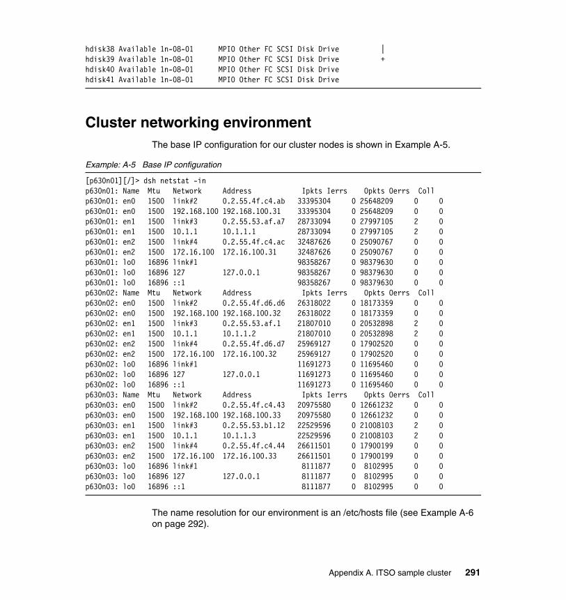
hdisk38 Available 1n-08-01 MPIO Other FC SCSI Disk Drive |hdisk39 Available 1n-08-01 MPIO Other FC SCSI Disk Drive +hdisk40 Available 1n-08-01 MPIO Other FC SCSI Disk Drivehdisk41 Available 1n-08-01 MPIO Other FC SCSI Disk Drive
Cluster networking environmentThe base IP configuration for our cluster nodes is shown in Example A-5.
Example: A-5 Base IP configuration
[p630n01][/]> dsh netstat -inp630n01: Name Mtu Network Address Ipkts Ierrs Opkts Oerrs Collp630n01: en0 1500 link#2 0.2.55.4f.c4.ab 33395304 0 25648209 0 0p630n01: en0 1500 192.168.100 192.168.100.31 33395304 0 25648209 0 0p630n01: en1 1500 link#3 0.2.55.53.af.a7 28733094 0 27997105 2 0p630n01: en1 1500 10.1.1 10.1.1.1 28733094 0 27997105 2 0p630n01: en2 1500 link#4 0.2.55.4f.c4.ac 32487626 0 25090767 0 0p630n01: en2 1500 172.16.100 172.16.100.31 32487626 0 25090767 0 0p630n01: lo0 16896 link#1 98358267 0 98379630 0 0p630n01: lo0 16896 127 127.0.0.1 98358267 0 98379630 0 0p630n01: lo0 16896 ::1 98358267 0 98379630 0 0p630n02: Name Mtu Network Address Ipkts Ierrs Opkts Oerrs Collp630n02: en0 1500 link#2 0.2.55.4f.d6.d6 26318022 0 18173359 0 0p630n02: en0 1500 192.168.100 192.168.100.32 26318022 0 18173359 0 0p630n02: en1 1500 link#3 0.2.55.53.af.1 21807010 0 20532898 2 0p630n02: en1 1500 10.1.1 10.1.1.2 21807010 0 20532898 2 0p630n02: en2 1500 link#4 0.2.55.4f.d6.d7 25969127 0 17902520 0 0p630n02: en2 1500 172.16.100 172.16.100.32 25969127 0 17902520 0 0p630n02: lo0 16896 link#1 11691273 0 11695460 0 0p630n02: lo0 16896 127 127.0.0.1 11691273 0 11695460 0 0p630n02: lo0 16896 ::1 11691273 0 11695460 0 0p630n03: Name Mtu Network Address Ipkts Ierrs Opkts Oerrs Collp630n03: en0 1500 link#2 0.2.55.4f.c4.43 20975580 0 12661232 0 0p630n03: en0 1500 192.168.100 192.168.100.33 20975580 0 12661232 0 0p630n03: en1 1500 link#3 0.2.55.53.b1.12 22529596 0 21008103 2 0p630n03: en1 1500 10.1.1 10.1.1.3 22529596 0 21008103 2 0p630n03: en2 1500 link#4 0.2.55.4f.c4.44 26611501 0 17900199 0 0p630n03: en2 1500 172.16.100 172.16.100.33 26611501 0 17900199 0 0p630n03: lo0 16896 link#1 8111877 0 8102995 0 0p630n03: lo0 16896 127 127.0.0.1 8111877 0 8102995 0 0p630n03: lo0 16896 ::1 8111877 0 8102995 0 0
The name resolution for our environment is an /etc/hosts file (see Example A-6 on page 292).
Appendix A. ITSO sample cluster 291

Example: A-6 Sample /etc/hosts file
127.0.0.1 loopback localhost# On each node, en0, en1 are connected to the same HACMP network and are in the# same VLAN (net_ether_01)# Base IP addresses for en0 192.168.100.31 p630n01192.168.100.32 p630n02192.168.100.33 p630n03
# Base IP addresses for en1172.16.100.31 n01bt1172.16.100.32 n02bt1172.16.100.33 n03bt1
# Base IP addreses for en2 (on secondary network - net_ether_02)10.1.1.1 gp0110.1.1.2 gp0210.1.1.3 gp03
# HACMP Service Labels192.168.110.131 n01sv1192.168.110.132 n02sv1192.168.110.133 n03sv1
# HACMP Persistent Address192.168.200.31 p630n01_per192.168.200.32 p630n02_per192.168.200.33 p630n03_per
Application scriptsThe application scripts (Example A-7 to Example A-10 on page 293) are provided as is, they do not perform “useful” work, and are intended to be used for testing the cluster.
Example: A-7 Application script for app1
#!/bin/ksh# This script must be copied in the shared file system /app1 in /app1/bin# directory.# The script will create is own directorties and log files.# This is jus a bogus script that creares some counters....# Use the application start, stop and monitoring scripts provided together# with this package!!!!# The scripts are “As Is”; Have fun!!! # Your ITSO pSeries cluster team
292 IBM Eserver pSeries HACMP V5.x Certification Study Guide Update

APPNAME=`basename $0`echo $APPNAMEif [[ -d /app1/log ]]; then rm -f /app1/log/$APPNAME.log else mkdir /app1/logfitouch /app1/log/$APPNAME.runningAPP_PID=`ps -aef |grep $APPNAME|grep -v grep|awk '{print $2}'`echo "$APP_PID">/app1/log/$APPNAME.pidSEQA=0SEQB=0while [[ -f /app1/log/$APPNAME.running ]]dosleep 10echo "${SEQB}:${SEQA}:${APPNAME}:$(date)">>/app1/log/$APPNAME.loglet SEQA=$SEQA+1if [[ $SEQA -gt 10 ]];then if [[ -f /app1/log/$APPNAME.log.1 ]];then rm /app1/log/$APPNAME.log.1 fi mv /app1/log/$APPNAME.log /app1/log/$APPNAME.log.1 touch /app1/log/$APPNAME.log let SEQB=$SEQB+1 let SEQA=0fidoneexit 0
Example: A-8 Application start script for app1
#!/bin/ksh# For more info, see the comments in the application script!!!!/app1/bin/app1.sh &exit 0
Example: A-9 Application stop script for app1
#!/bin/ksh# For more info, see the comments in the application script!!!!rm -f /app1/log/app1.sh.runningexit 0
Example: A-10 Application monitoring scripts (custom monitor) for app1
#!/bin/ksh# For more info, see the comments in the application script!!!!PID=$(ps -ef |grep '/app1/bin/app1.sh' |grep -v grep)if [[ -z "$PID" ]];then
Appendix A. ITSO sample cluster 293

exit 1fiexit 0
Answers to the quizzesHere are the answers to the quizzes from the earlier chapters.
Chapter 2 quiz1. b2. c3. b4. a,d5. b6. b7. a8. c9. d10.b11.a12.d13.d14.c15.d16.a17.c18.b19.b20.d21.b
Chapter 3 quiz1. b2. a3. b4. c5. b6. c7. d8. b9. a
294 IBM Eserver pSeries HACMP V5.x Certification Study Guide Update

10.c11.c12.a13.c14.c15.c16.c17.b18.b19.c20.a
Chapter 4 quiz1. c2. a3. b4. c5. b
Chapter 5 quiz1. b2. a3. a,d4. b,d5. c6. c7. d8. a9. b10.a11.d12.c13.a14.b15.c16.a17.a18.d19.b20.c
Appendix A. ITSO sample cluster 295

296 IBM Eserver pSeries HACMP V5.x Certification Study Guide Update

acronyms
RAIDFCACD Active Configuration Directory
ATM Asynchronous Transfer Mode
CLVM Concurrent Logical Volume Manager
CRM Concurrent Resource Manager
CSM Cluster System Management
C-SPOC Cluster Single Point of Control
CWOF Cascading Without Fallback
DARE Dynamic Reconfiguration
DCD Default Configuration Directory
DLPAR Dynamic LPAR
DNP Dynamic Node Priority
DNS Dynamic Name Services
ECM Enhanced Concurrent Mode
ES Enhanced Scalability
FC Fibre Channel
FDDI Fiber Distributed Data Interface
GPFS General Parallel File System
GUI Graphical User Interface
HACMP High Availability Cluster Multi-Processing
HAGEO High Availability Geographic cluster
HAS High Availability Subsystem
HBA Host Bus Adapter
HMC Hardware Management Console
HPS High Performance Switch
HWAT Hardware Address Takeover
IBM International Business Machines Corporation
Abbreviations and
© Copyright IBM Corp. 2004, 2006. All rights reserved
IP Internet Protocol
IPAT IP Address Takeover
ITSO International Technical Support Organization
LPAR Logical Partition
LVCB Logical Volume Control Block
LVM Logical Volume Manager
MPIO Multi-Path IO
NFS Network File System
NIC Network Interface Card
NIM Network Interface Module or Network Install Manager
NIS Network Information Services
ODM Object Data Manager
OLPW On-Line Planning Worksheets
POL Priority Override Location
PVID Physical Volume ID
RAID Redundant Array of Independent Disks
RG Resource Group
RMC Resource Monitoring and Control
RPD RSCT Peer Domain
RSCT Reliable Scalable Clustering Technology
SAN Storage Area Network
SCD Staging Configuration Directory
SCSI Small Computer System Interface
SDD Subsystem Device Driver
SMIT System Management Tool Interface
SMP Symmetric Multi-Processing
. 297

SNA System Network Architecture
SNMP Simple Network Management Protocol
SPOF Single Point Of Failure
SSA Serial Storage Architecture
SSL Secure Socket Layer
TCP Transmission Control Protocol
UDP Universal Datagram Protocol
VG Volume Group
VGDA Volume Group Descriptor Area
VPATH Virtual Path
VSD Virtual Shared Disk
XD Extended Distance
298 IBM Eserver pSeries HACMP V5.x Certification Study Guide Update

Related publications
The publications listed in this section are considered particularly suitable for a more detailed discussion of the topics covered in this redbook.
IBM RedbooksFor information on ordering these publications, see “How to get IBM Redbooks” on page 300. Note that some of the documents referenced here may be available in softcopy only.
� Configuring Highly Available Clusters Using HACMP V4.5, SG24-6845
� Exploiting HACMP V4.4: Enhancing the Capabilities of Cluster Multi-Processing, SG24-5979
� An Introduction to Security in a CSM 1.3 for AIX 5L Environment, SG24-6873
Other publicationsThese publications are also relevant as further information sources:
� Advanced SerialRAID Adapter: Installation Guide, SA33-3287
� AIX 5L Version 5.2 Installation Guide and Reference, SC23-4389
� General Parallel File System (GPFS) for AIX 5L in an RSCT peer domain: Concepts, Planning, and Installation, GA22-7974
� HACMP Administration Guide, SC23-4862
� HACMP Planning and Installation Guide, SC23-4861
� HACMP Smart Assist for WebSphere User’s Guide, SC23-4877
� High Availability Clusters Multi-Processing XD (Extended Distance) for HAGEO Technology: Planning and Administration Guide, SA22-7956
� High Availability Cluster Multi-Processing XD (Extended Distance) V5.1: Concepts and Facilities for HAGEO Technology, SA22-7955
� IBM Reliable Scalable Cluster Technology Administration Guide, SA22-7889
� IBM TotalStorage Enterprise Storage Server Service Guide 2105 Model 750/800 and Expansion Enclosure, Volume 1, SY27-7635
© Copyright IBM Corp. 2004, 2006. All rights reserved. 299

� IBM TotalStorage FAStT900 Fibre Channel Storage Server Installation Guide, GC26-7530
� IBM TotalStorage FAStT Storage Manager 8.4 Installation and Support Guide for Intel-based Operating Environments, GC26-7589
Online resourcesThese Web sites and URLs are also relevant as further information sources:
� Availant, Inc.
http://www.availant.com
� HACMP fixes and updates
http://techsupport.services.ibm.com/server/cluster/
� HACMP support Web site
http://www-1.ibm.com/servers/eserver/pseries/ha/
� IBM Enterprise Storage Server Web site
http://www.storage.ibm.com/disk/ess/index.html
� IBM ^Support Fix Central
http://www-912.ibm.com/eserver/support/fixes/fcgui.jsp
� IBM TotalStorage® DS4000 series
http://www.storage.ibm.com/disk/fastt/index.html
How to get IBM RedbooksYou can search for, view, or download Redbooks, Redpapers, Hints and Tips, draft publications and Additional materials, as well as order hardcopy Redbooks or CD-ROMs, at this Web site:
ibm.com/redbooks
Help from IBMIBM Support and downloads
ibm.com/support
IBM Global Services
ibm.com/services
300 IBM Eserver pSeries HACMP V5.x Certification Study Guide Update

Index
Symbols/.rhosts 5, 31–32/etc/exports 52/etc/firstboot 82/etc/hosts 36/etc/inittab 32/etc/services 267/usr/es/lpp/cluster/doc 71/usr/es/sbin/cluster/etc/clinfo.rc 53/usr/es/sbin/cluster/etc/exports 52/usr/es/sbin/cluster/snapshots 82/usr/sbin/cluster/etc/rhosts 33/var/hacmp/clcomd/clcomd.log 54/var/hacmp/clcomd/clcomddiag.log 54/var/hacmp/clverify/clverify.log 54
Numerics2105-800 397133 39
Aactive 102active ODM 83adapters 19Apache 59application 17
monitoring 4recovery 3
application compatibility 50application monitoring 50, 59application monitors 272application server 51application start script 55application startup monitoring 259application stop script 55ARP 30, 53ARP cache 53ATM 26–27authentication 31auto correction 258automated configuration discovery 4automated fallover 6
© Copyright IBM Corp. 2004, 2006. All rights reserved
automatic cluster verification 258, 269
Bbase IP address 26BIND 36boot interface 25bridges 21Bring Offline 59
CCapacity Upgrade on Demand 259cascading 52, 56, 114cascading with out fallback 4change management 2, 20cl_rcp 32cl_rsh 32clcomdES 31–33, 53, 72, 76, 268clconvert_snapshot 76, 85clhosts 262client 11, 20Clinfo 53clinfoES 262cllockdES 32clrexec 32clsmuxpdES 32, 262clstrmgr 80clstrmgrES 32, 80, 262cluster 10cluster communication daemon 5, 31cluster configuration 262
further automation 262Cluster Lock Manager 14cluster manager 262cluster multi-processing 3cluster partitioning 87cluster synchronization 37Cluster Test Tool 263cluster verification 262cluster.es.clvm 72clverify 33, 53clverify.log 54clvmd 36command
. 301

varyonvg 44communication adapter 22communication device 22, 123communication interface 18, 22–23concurrent 19, 34, 56, 58, 100, 114, 133concurrent active 41concurrent resource manager 86config_too_long 81configuration simplification 4Configuration_Files 268connectivity 20CRM 86C-SPOC 4–5, 32, 42, 78, 101ctsec 259CUoD 259, 279custom 56, 58, 114, 133custom monitoring 59custom resource groups 4customized event scripts 74, 76CWOF 57, 133
DD40 39DARE 32data protection 21delayed fallback timer 135disaster 12disaster recovery planning 17disk 7disk adapter 7, 18disk heartbeat 23, 27disk mirroring 92diskhb 27, 35, 89, 121DNP 57dominance (HAGEO) 119downtime 2
planned 2, 20unplanned 2, 20
Dynamic LPAR 279Dynamic Node Priority 56dynamic reconfiguration 32
EE10 39E20 39ECM 41, 102–103, 259, 280enhanced concurrent 36, 41, 101enhanced concurrent mode 41
eRCMF 260ESS 14, 39, 45Etherchannel 28Ethernet 26–27Event Management 260event scripts 4exportfs 71extended 104, 111extended distance 11
FF10 39F20 39failure detection 6, 12failure notification 23fallback 10fallback preferences 59Fallback To Higher Priority Node 59fallover 10fallover preferences 59Fallover To Next Priority Node In The List 59Fallover Using Dynamic Node Priority 59Fast 41fast disk takeover 5, 41, 263FAStT 45FAStT Storage manager 94FAStT900 94fault tolerance 1fault tolerant systems 7FCS 27FDDI 26–27Fibre Channel 19, 35, 39, 46file collections 5, 258file system 41, 43FlashCopy 95floating licenses 52forced 82forced varyon 44forced varyon of volume groups 5
Ggeneric applications 8geographic topology 13GeoMessage 13GeoMirror 13geo-mirroring 12GeoRM 61, 262global network 87
302 IBM Eserver pSeries HACMP V5.x Certification Study Guide Update

GLVM 262godm 33graceful with takeover 79
HHACMP subnets 29HACMP V5.2 5HACMP/XD 11HACMP_Files 268HACMPadapter 33, 37HACMPnode 33HAGEO 11–12, 61, 63, 118
concurrent configurations 14standby configurations 14takeover configurations 14
HA-NFS 4, 51hardware address takeover 30HAS 4hearbeat over IP aliases 36heartbeat 27, 32–33, 87heartbeat messages 20heartbeat over IP aliases 27, 37, 88heartbeat ring 38heartbeating 33
disk heartbeat 4IP aliases 5
high availability 1, 6, 8, 20concepts 1
high availability cluster 17Host Bus Adapter 47HPS 27HWAT 30
Iifconfig 29Inactive Takeover 56, 133, 135initiator 90IP address takeover 21IP address takeover via IP aliasing 28IP alias 21, 24IP label 22, 33IP replacement 21, 28IPAT 21, 28IPAT via aliasing 28IPAT via IP aliasing 29IPAT via IP replacement 29–30, 120
JJFS 41JFS2 41
KKA 34–35keep alive 34
LLAA 30licensing 50llback 56logical partition 43logical volume 43long running monitors 272LPAR 10, 18, 21lpp_source 71lppchk 72, 75LUN masking 45lvlstmajor 99LVM 36LVM mirroring 21, 40, 91
MMAC 30, 37masking service interruptions 20memory 19message authentication 259migration 78mirroring 8MPIO 49
Nnetmask 37network 6–7, 21, 27, 86network adapter 6–7network distribution policy 265Network Installation Management 71network interface card 86network properties 28network topology 20, 23networks 17Never Fallback 59NFS 48, 51NFS locking 52NIM 33, 154node 7, 10
Index 303

node distribution policy 265node failover 19node reintegration 19node_down 118node_up 118node-bound 25node-bound service IP address 23node-by-node 77node-by-node migration 73non-concurrent 19, 100non-IP network 21, 27, 35, 87–88non-service interface 26
OODM 23, 31–32
HACMPadapter 33HACMPnode 33
OLPW 259Online On All Available Nodes 59Online On First Available Node 58Online On Home Node Only 58Online Planning Worksheets 5, 49operational procedures 9optic fiber 36
Ppassive 41, 102persistent IP addresses 88persistent IP label 25physical partition 43physical volume 42physical volume ID 36PING_CLIENT_LIST 53planning 17point to point non-IP networks 34point-to point 90point-to-point non-IP network 23PPRC 14, 262process monitoring 59pSeries 10PV 42PVID 36, 84
Qquorum 43
RRAID 7, 21, 40, 42, 47, 91RAID0 91RAID1 92RAID10 93RAID2 92RAID3 92RAID4 92RAID5 93raw logical volumes 41, 100raw physical volumes 41recovery 34Redbooks Web site 300
Contact us xiiireintegration 6, 15Reliable Scalable Cluster Technology 5remote mirror option 95resource 9–10resource group 22, 25, 30, 54, 91
dependencies 6RESOURCE Group (RG) 262resource group dependencies 259resource groups dependencies 270resource monitoring and control 6Restart Count 60rexec 33RMC 6, 51, 260rolling migration 73, 77rotating 56–57, 114routers 21RS/6000 21RS232 23, 35, 89, 121RSCT 4, 23, 32–33, 36–37, 81, 87, 258, 262, 279
Event management 6rsh 33run-time policy 114
SSAN 35SCSI 19, 35, 39, 90secure shell 280security 31, 114service interface 25service IP address 5, 22service IP label 22settling time 134shared LVM 40shared service IP address 23
304 IBM Eserver pSeries HACMP V5.x Certification Study Guide Update

shared storage 19, 91shared tape 40single point 262single points of failure 2site 12site failure 15sizing 17SLIP 27SMIT
Extended configuration 4Standard configuration 4
SMP 52SNA 24snapshot 75snapshot conversion 72SOCC 27SP 21SP Switch 27split brain 34, 41, 87SPOF 2, 8, 21SRC 32SSA 19, 47, 90SSA concurrent mode 42SSA router 266SSA router device 90ssar 90ssh 280Standard 104standby license 50startup preferences 58storage 17, 19storage partitioning 95striping 91subnets 37supported upgrades 84switches 21
TT40 39takeover 11target 90target mode SCSI 23, 35target mode SSA 23, 35TCP/IP networks 34TCP/IP subsystem 7testing 9tmscsi 27, 89–90, 121tmssa 27, 87, 89, 121
Token Ring 26–27topology 9, 38
Uuser password management 5, 259
Vvaryoffvg 101VGDA 43volume group 42volume group descriptor area 43volumecopy 95VPATH 49VPN 31
WWeb based SMIT 258, 270
XX.25 24
Zzoning 45
Index 305

306 IBM Eserver pSeries HACMP V5.x Certification Study Guide Update

(0.5” spine)0.475”<
->0.875”
250 <->
459 pages
IBM E
server pSeries HACM
P V5.x Certification Study Guide Update


®
SG24-6375-01 ISBN 073849416X
INTERNATIONAL TECHNICALSUPPORTORGANIZATION
BUILDING TECHNICALINFORMATION BASED ONPRACTICAL EXPERIENCE
IBM Redbooks are developed by the IBM International Technical Support Organization. Experts from IBM, Customers and Partners from around the world create timely technical information based on realistic scenarios. Specific recommendations are provided to help you implement IT solutions more effectively in your environment.
For more information:ibm.com/redbooks
IBM Eserver pSeries HACMP V5.x Certification StudyGuide Update
The latest HACMP features are explained
Sample exercise questions are included
Use as a deskside reference guide
IBM HACMP 5.x for AIX 5L (V5.1, V5.2, and the new HACMP 5.3) has introduced major changes to the well-proven IBM high availability solution for IBM ̂pSeries clusters. The changes include product usability enhancements, performance, and integration with the IBM strategic On Demand initiative.
This IBM Redbook provides information for system administrators who want to implement high availability clusters with HACMP V5.x, upgrade an existing cluster to the latest version, or prepare for the HACMP V5.x certification exam to achieve IBM Eserver Certified Systems Expert - pSeries HACMP 5.x for AIX 5L.
The pSeries HACMP 5.x for AIX 5L certification validates the skills required to successfully plan, install, configure, and support an HACMP 5.x for AIX 5L cluster installation. The requirements for this include a working knowledge of:
� Hardware options� AIX 5L parameters� The cluster and resource configuration process� Customization of the standard HACMP 5.x facilities� Diagnosis and troubleshooting
This redbook helps AIX 5L professionals seeking a comprehensive and task-oriented guide for developing the knowledge and skills required for the certification. It is designed to provide a combination of theory and practical experience. Due to the practical nature of the certification content, this publication can also be used as a deskside reference.
Back cover