Embed Size (px)
Citation preview
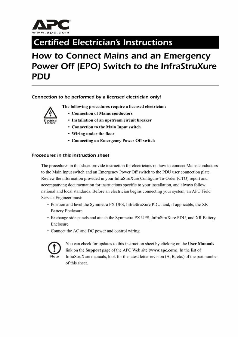
Certified Electrician’s Instructions
How to Connect Mains and an Emergency Power Off (EPO) Switch to the InfraStruXure PDU
Connection to be performed by a licensed electrician only!
Procedures in this instruction sheet
The procedures in this sheet provide instruction for electricians on how to connect Mains conductors to the Main Input switch and an Emergency Power Off switch to the PDU user connection plate. Review the information provided in your InfraStruXure Configure-To-Order (CTO) report and accompanying documentation for instructions specific to your installation, and always follow national and local standards. Before an electrician begins connecting your system, an APC Field Service Engineer must:
� Position and level the Symmetra PX UPS, InfraStruXure PDU, and, if applicable, the XR Battery Enclosure.
� Exchange side panels and attach the Symmetra PX UPS, InfraStruXure PDU, and XR Battery Enclosure.
� Connect the AC and DC power and control wiring.
ElectricalHazard
The following procedures require a licensed electrician:� Connection of Mains conductors� Installation of an upstream circuit breaker� Connection to the Main Input switch� Wiring under the floor� Connecting an Emergency Power Off switch
Note
You can check for updates to this instruction sheet by clicking on the User Manuals link on the Support page of the APC Web site (www.apc.com). In the list of InfraStruXure manuals, look for the latest letter revision (A, B, etc.) of the part number of this sheet.

This manual is available in English on the enclosed CD.Dieses Handbuch ist in Deutsch auf der beiliegenden CD-ROM verfügbar.Este manual está disponible en español en el CD-ROM adjunto. Ce manuel est disponible en français sur le CD-ROM ci-inclus.Questo manuale è disponibile in italiano nel CD-ROM allegato.Instrukcja Obsługi w jezyku polskim jest dostepna na CD.Deze handleiding staat in het Nederlands op de bijgesloten cd.
您可以从包含的 CD 上获得本手册的中文版本。
Certified Electrician�s Instructions
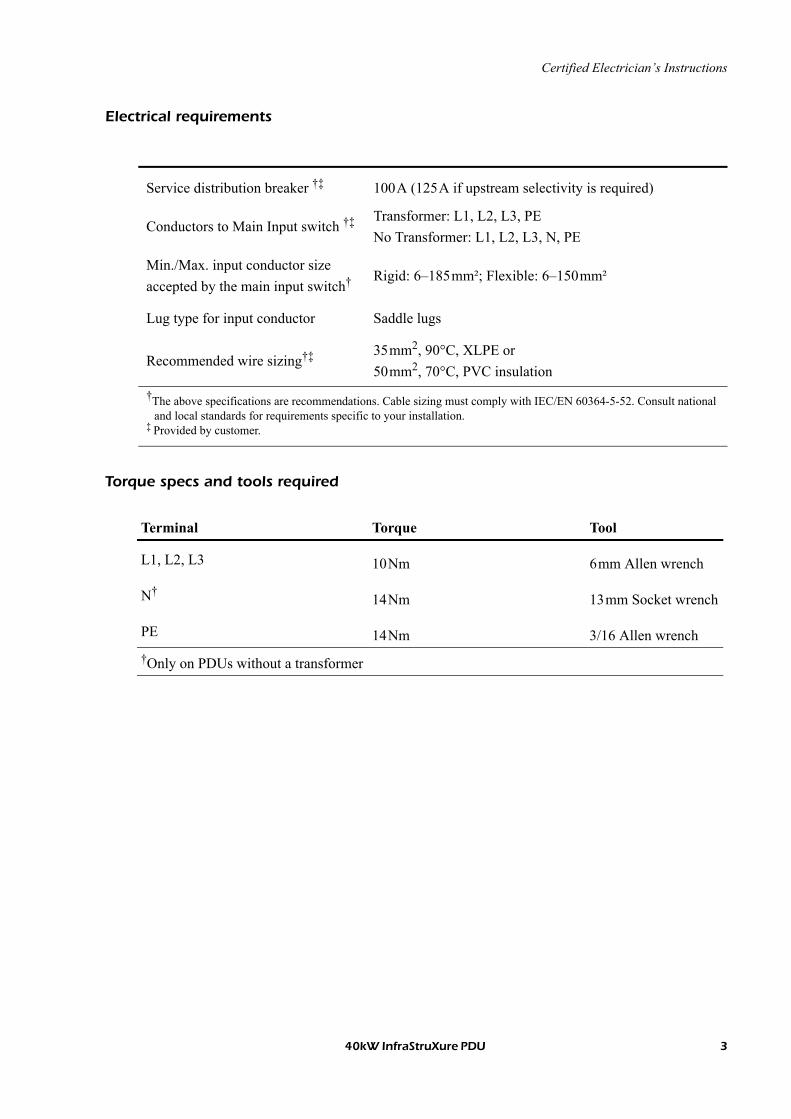
Electrical requirements
Torque specs and tools required
Service distribution breaker �� 100A (125A if upstream selectivity is required)
Conductors to Main Input switch �� Transformer: L1, L2, L3, PENo Transformer: L1, L2, L3, N, PE
Min./Max. input conductor size accepted by the main input switch� Rigid: 6�185mm²; Flexible: 6�150mm²
Lug type for input conductor Saddle lugs
Recommended wire sizing�� 35mm2, 90°C, XLPE or50mm2, 70°C, PVC insulation
�The above specifications are recommendations. Cable sizing must comply with IEC/EN 60364-5-52. Consult national and local standards for requirements specific to your installation.
� Provided by customer.
Terminal Torque Tool
L1, L2, L3 10Nm 6mm Allen wrench
N�14Nm 13mm Socket wrench
PE 14Nm 3/16 Allen wrench�Only on PDUs without a transformer
40kW InfraStruXure PDU 3
Certified Electrician�s Instructions
4 40kW InfraStruXure PDU
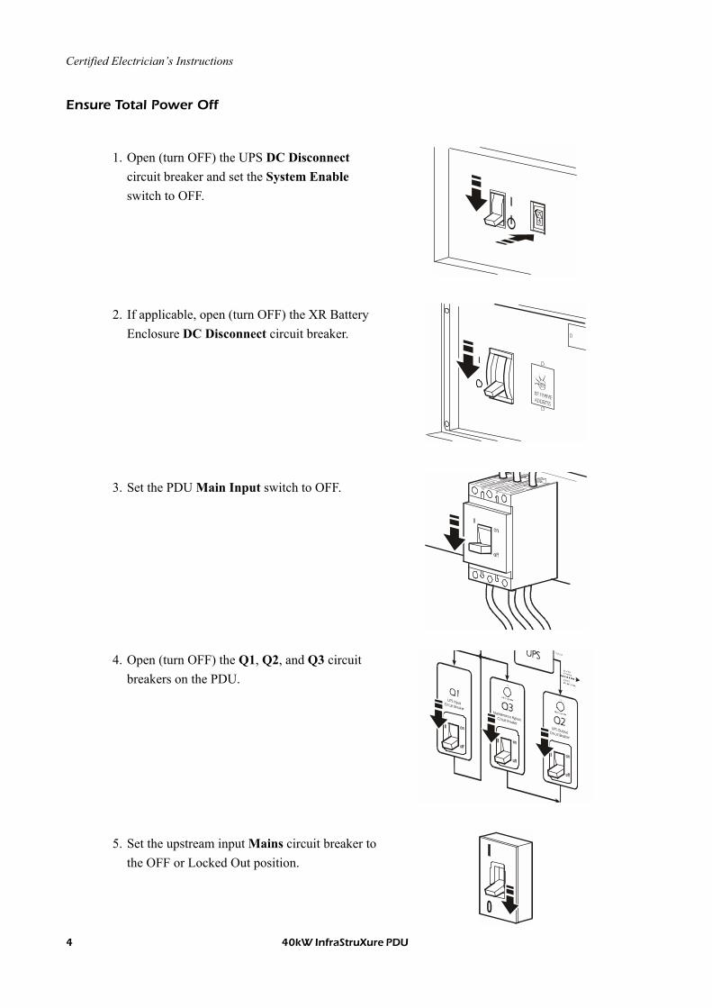
Ensure Total Power Off
1. Open (turn OFF) the UPS DC Disconnect circuit breaker and set the System Enable switch to OFF.
2. If applicable, open (turn OFF) the XR Battery Enclosure DC Disconnect circuit breaker.
3. Set the PDU Main Input switch to OFF.
4. Open (turn OFF) the Q1, Q2, and Q3 circuit breakers on the PDU.
5. Set the upstream input Mains circuit breaker to the OFF or Locked Out position.
Certified Electrician�s Instructions
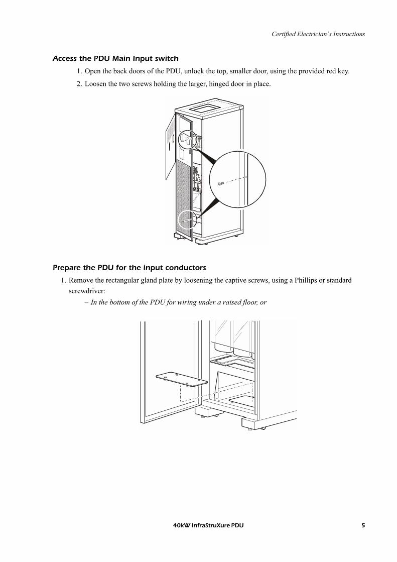
Access the PDU Main Input switch
1. Open the back doors of the PDU, unlock the top, smaller door, using the provided red key.
2. Loosen the two screws holding the larger, hinged door in place.
Prepare the PDU for the input conductors
1. Remove the rectangular gland plate by loosening the captive screws, using a Phillips or standard screwdriver:
� In the bottom of the PDU for wiring under a raised floor, or
40kW InfraStruXure PDU 5
Certified Electrician�s Instructions
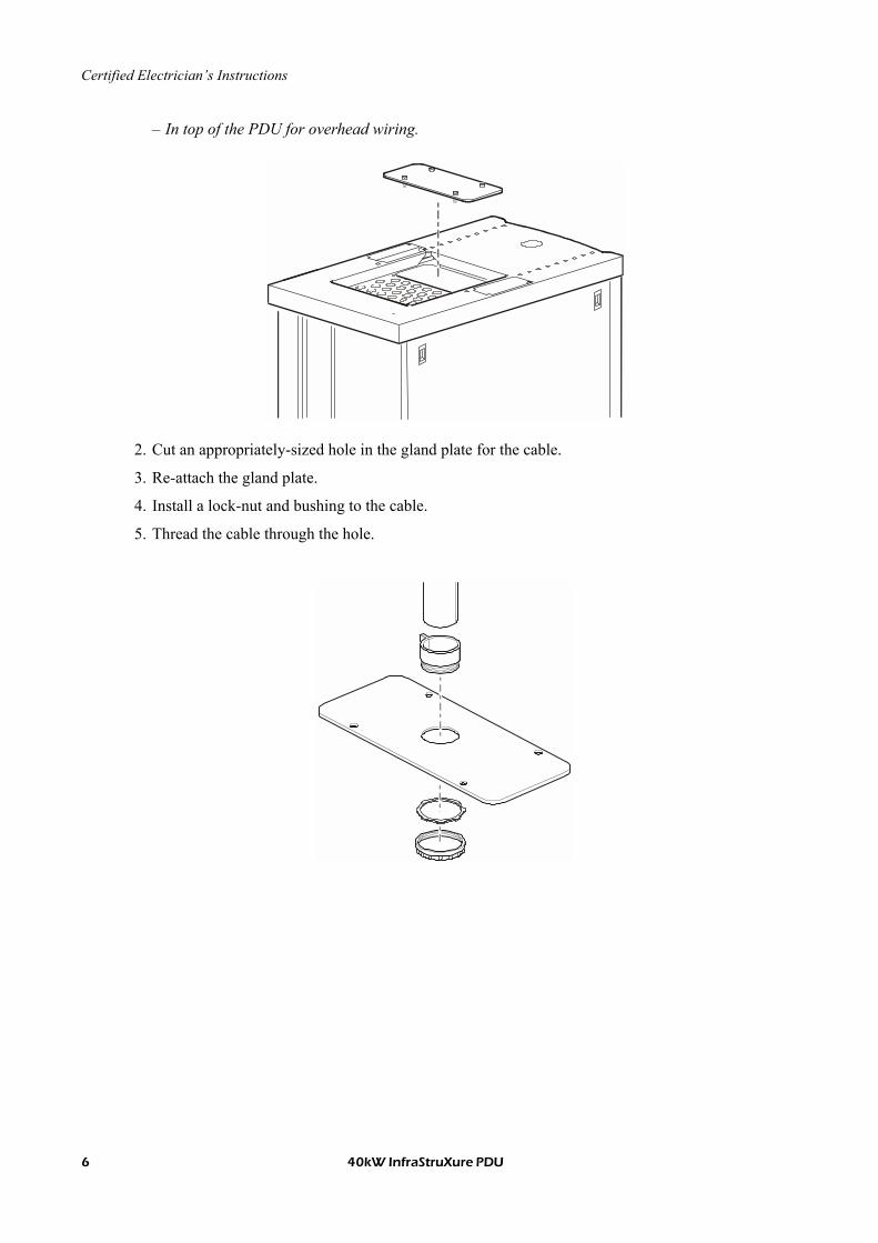
� In top of the PDU for overhead wiring.
2. Cut an appropriately-sized hole in the gland plate for the cable.
3. Re-attach the gland plate.
4. Install a lock-nut and bushing to the cable.
5. Thread the cable through the hole.
6 40kW InfraStruXure PDU
Certified Electrician�s Instructions
Install a circuit breaker
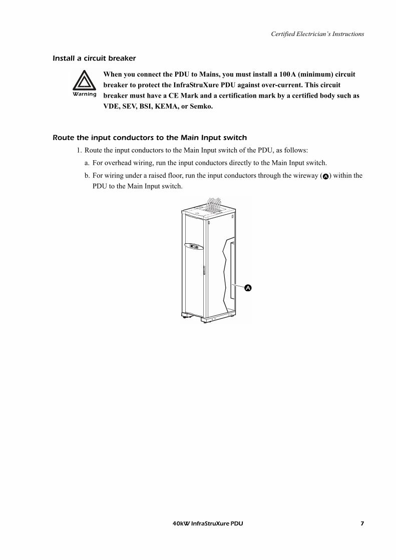
Route the input conductors to the Main Input switch
1. Route the input conductors to the Main Input switch of the PDU, as follows:
a. For overhead wiring, run the input conductors directly to the Main Input switch.
b. For wiring under a raised floor, run the input conductors through the wireway () within the PDU to the Main Input switch.
Warning
When you connect the PDU to Mains, you must install a 100A (minimum) circuit breaker to protect the InfraStruXure PDU against over-current. This circuit breaker must have a CE Mark and a certification mark by a certified body such as VDE, SEV, BSI, KEMA, or Semko.
40kW InfraStruXure PDU 7
Certified Electrician�s Instructions
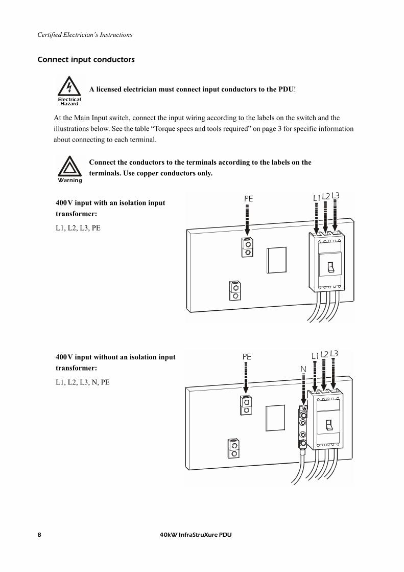
Connect input conductors
At the Main Input switch, connect the input wiring according to the labels on the switch and the illustrations below. See the table �Torque specs and tools required� on page 3 for specific information about connecting to each terminal.
ElectricalHazard
A licensed electrician must connect input conductors to the PDU!
Warning
Connect the conductors to the terminals according to the labels on the terminals. Use copper conductors only.
400V input with an isolation input transformer:
L1, L2, L3, PE
PE L1 L2 L3
400V input without an isolation input transformer:
L1, L2, L3, N, PE
PE L1 L2 L3
8 40kW InfraStruXure PDU
Certified Electrician�s Instructions
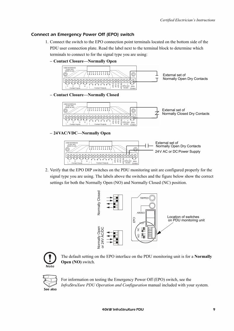
Connect an Emergency Power Off (EPO) switch
1. Connect the switch to the EPO connection point terminals located on the bottom side of the PDU user connection plate. Read the label next to the terminal block to determine which terminals to connect to for the signal type you are using:� Contact Closure�Normally Open
� Contact Closure�Normally Closed
� 24VAC/VDC�Normally Open
2. Verify that the EPO DIP switches on the PDU monitoring unit are configured properly for the signal type you are using. The labels above the switches and the figure below show the correct settings for both the Normally Open (NO) and Normally Closed (NC) position.
Note
The default setting on the EPO interface on the PDU monitoring unit is for a Normally Open (NO) switch.
See also
For information on testing the Emergency Power Off (EPO) switch, see the InfraStruXure PDU Operation and Configuration manual included with your system.
1 2 3 4
ATS
EN
ATS
0
ATS
1AT
S 2
EPO Contact
� +EPO 24VAC/DCContact Inputs Contact Outputs
USER INTERFACE© 2001 APC
MADE IN USA
External set of Normally Open Dry Contacts
1 2 3 4AT
S E
N
ATS
0
ATS
1AT
S 2
EPO Contact
� +EPO 24VAC/DCContact Inputs Contact Outputs
USER INTERFACE© 2001 APC
MADE IN USA
External set of Normally Closed Dry Contacts
1 2 3 4
ATS
EN
ATS
0
ATS
1AT
S 2
EPO Contact
� +EPO 24VAC/DCContact Inputs Contact Outputs
USER INTERFACE© 2001 APC
MADE IN USA
24V AC or DC Power Supply
External set of Normally Open Dry Contacts
NO
NC
TRIPPED
ARMED
TESTEPO
Nor
mal
ly C
lose
dN
orm
ally
Ope
nor
24V
AC
/DC
Location of switcheson PDU monitoring unit
40kW InfraStruXure PDU 9


*990-1595B-001*
APC Worldwide Customer Support
Customer support for this or any other APC product is available at no charge in any of the following ways:
� Visit the APC Web site to access documents in the APC Knowledge Base and to submit customer support requests.
� www.apc.com (Corporate Headquarters)Connect to localized APC Web sites for specific countries, each of which provides customer support information.
� www.apc.com/support/Global support searching APC Knowledge Base and using e-support.
� Contact an APC Customer Support center by telephone or e-mail.
� Regional centers:
� Local, country-specific centers: go to www.apc.com/support/contact for contact information.
Contact the APC representative or other distributor from whom you purchased your APC product for information on how to obtain local customer support.
InfraStruXure Technical Support (1)(877)537-0607 (toll free)
APC headquarters U.S., Canada (1)(800)800-4272 (toll free)
Latin America (1)(401)789-5735 (USA)
Europe, Middle East, Africa (353)(91)702020 (Ireland)
Australia, New Zealand, Pacific (61)(2)9955-9366 (Australia)
Entire contents © 2005 American Power Conversion. All rights reserved. Reproduction in whole or in part without permission is prohibited. APC, the APC logo, and InfraStruXure are trademarks of American Power Conversion Corporation and may be registered in some
jurisdictions. All other trademarks, product names, and corporate names are the property of their respective owners and are used for informational purposes only.
990-1595B-001 04/2005