Embed Size (px)
Citation preview
1
W415-0682 / C / 11.08.10$10.00
INSTALLATION INSTRUCTIONS
INSTALLER: LEAVE THESE INSTRUCTIONS WITH THE APPLIANCE THIS TERMINAL IS SERVING.CONSUMER: RETAIN THESE INSTRUCTIONS FOR FUTURE REFERENCE.
THESE INSTRUCTIONS ARE TO BE USED IN CONJUNCTION WITH THE APPLIANCE AND PVA INSTRUCTIONS.
C E RT I F I E D
Wolf Steel Ltd., 24 Napoleon Rd., Barrie, ON, L4M 4Y8 Canada / 103 Miller Drive, Crittenden, Kentucky, USA, 41030
0 21 1212 fa 0 22 031 .napoleonfireplace .co a k napoleon.on.ca.continentalfireplace .co a k continentalfire.on.ca
CERTIFIED UNDER CANADIAN AND AMERICAN NATIONAL STANDARDS: ANSI Z21.88 CSA 2.33 FOR VENTED GAS FIREPLACE HEATERS AND ANSI Z21. CSA 2.22 FOR VENTED GAS FIREPLACES.
GENERAL INFORMATION These Installation Instructions must be used in conjunction with the appliance and appropriate PVA adapter kit Installation Instructions. Clearances listed in these Instructions supersede those in the appliance's Installation Instructions.
Power venting of direct vent appliances may result in the reduction of efficiencies by as much as ten percent. Consider this in making any venting and heating decisions in any installation application.
SELECTING AND INSTALLING THE FIREPLACE When selecting a gas appliance for use with the GPV, take into consideration the various requirements and limitations in the venting installation section for the following models:
Models Equipped with an Intermittent Pilot Ignition (I.P.I.)It is recommended that the GPV be used with a gas appliance equipped with an Intermittent Pilot Ignition (I.P.I.). Downward vertical vent runs are permitted with an I.P.I. system. See venting section in appropriate PVA Installation Instructions.
Models Equipped with Millivolt/ Standing PilotDownward vertical vent runs are not permitted with a standing pilot system. See venting section in appropriate PVA Installation Instructions.
INSTALLATION TO BE DONE BY A QUALIFIED INSTALLER to conform with local codes. In absence of local codes install to the current National Building Code in Canada or to regional building codes in the United States. It must be electrically connected and grounded in accordance with local codes. In the absence of local codes, use the current CSA C22.1 CANADIAN ELECTRICAL CODE in Canada or the ANSI/NFPA 70 NATIONAL ELECTRIC CODE in the United States.
The GPV operates on 120 VAC 60 HZ electrical service which is supplied at the firebox junction box.
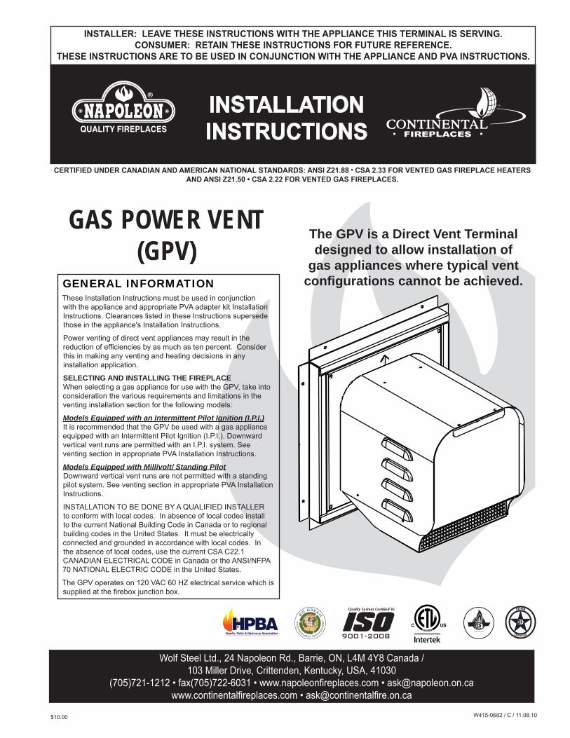
GAS POWER VENT (GPV)
The GPV is a Direct Vent Terminal designed to allow installation of
gas appliances where typical vent configurations cannot be achieved.
2
W415-0682 / C / 11.08.10
TABLE OF CONTENTS1.0 VENTING 2
1.1 INSTALLATION OVERVIEW 31.2 VENT TERMINAL CLEARANCES 41.3 VENT LENGTHS 51.4 POWER VENT TERMINAL 5
1.4.1 TERMINAL INSTALLATION 51.4.2 POWER VENT INSTALLATION 61.4.3 INITIAL FIRING PROCEDURES 61.4.4 ELECTRICAL BOX INSTALLATION 7
1.5 RESTRICTOR PLATE INSTALLATION 81.6 WIRING DIAGRAM AND INSTALLATION 8
1.6.1 SIT IPI 885 PROFLAME COMPLETE WITH GPV POWER VENT TERMINAL 81.6.2 SIT MILLIVOLT 820 NOVA COMPLETE WITH GPV POWER VENT TERMINAL 101.6.3 SIT IPI 880/886 PROFLAME COMPLETE WITH GPV POWER VENT TERMINAL 111.6.4 DEXEN IPI 6003-3V COMPLETE WITH GPV POWER VENT TERMINAL 12
2.0 ADJUSTMENTS 132.1 VENTURI ADJUSTMENTS 13
3.0 REPLACEMENTS 134.0 TROUBLE SHOOTING 14
NOTE: Changes, other than editorial, are denoted by a vertical line in the margin.
1.0 VENTINGThere are specifi c adaptors and venting requirements for each appliance, refer to your power vent adaptor leafl et for more information.
For complete installation instructions refer to the following web sites:
Manufacturer WebsiteNapoleon - English http://www.napoleonfi replaces.com/Tech/installation_manuals/installations.htmlNapoleon - French http://www.napoleonfoyers.com/Fireplaces/powervent.htmlContinental http://www.continentalfi replaces.com/fi replaces/gas/powervent.html
3
W415-0682 / C / 11.08.10
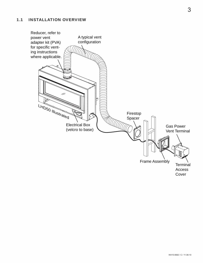
1.1 INSTALLATION OVERVIEW
A typical vent configuration
Reducer, refer to power vent adapter kit (PVA) for specific vent-ing instructions where applicable.
Gas Power Vent Terminal
Electrical Box (velcro to base)
LHD50 IllustratedFirestop Spacer
Frame AssemblyTerminal Access Cover

4
W415-0682 / C / 11.08.10
INSTALLATIONSCANADA U.S.A.
A 12” 12” Clearance above grade, veranda porch, deck or balcony.
B 12” Δ 9” Δ Clearance to windows or doors that open.
C 12” * 12” * Clearance to permanently closed windows.
D 18” ** 18” ** Vertical clearance to ventilated soffi ts located above the terminal within a horizontal distance of 2’ from the center line of the terminal.
E 12” ** 12” ** Clearance to unventilated soffi t.
F 0” 0” Clearance to an outside corner wall.
G0” 0” Clearance to an inside non-combustible corner wall or protruding non-combustible obstructions (chimney, etc.).
2” 2” Clearance to an inside combustible corner wall or protruding combustible obstructions (vent chase, etc.).
H 3’ 3’ *** Clearance to each side of the center line extended above the meter / regulator assembly to a maximum vertical distance of 15’.
I 3’ 3’ *** Clearance to a service regulator vent outlet.
J 12” 9” Clearance to a non-mechanical air supply inlet to the building or a combustion air inlet to any other appliance.
K 6’ 3’ Clearance to a mechanical air supply inlet.
L 7’ ‡ 7’ *** Clearance above a paved sidewalk or paved driveway located on public property.
M 12” †† 12” *** Clearance under a veranda, porch or deck.
N 12” 12” Clearance above the roof.
O 2’ †* 2’ †* Clearance from an adjacent wall including neighbouring buildings.
P 8’ 8’ Roof must be non-combustible without openings.
Q 3’ 3’ See chart for wider wall dimensions.
R 6’ 6’ See chart for deeper wall dimensions. The terminal shall not be installed on any wall that has an open-ing between the terminal and the open side of the structure.
S 12” 12” Clearance under a covered balcony
Δ The terminal shall not be located less than 6 feet under a window that opens on a horizontal plane in a structure with three walls and a roof.
* Recommended to prevent condensation on windows and thermal breakage
** It is recommended to maximize the distance to vinyl clad soffi ts.
*** This is a recommended distance. For additional requirements check local codes.
‡ A vent shall not terminate where it may cause hazardous frost or ice accumulations on adjacent property surfaces..
†† Permitted only if the veranda, porch, or deck is fully open on a minimum of two sides beneath the fl oor.
†* Recommended to prevent recirculation of exhaust products. For additional requirements check local codes.
††* Permitted only if the balcony is fully open on a minimum of one side.
12.2C
R
Q S
GP
COVERED BALCONY APPLICATIONS ††*
QMIN
R MAX
MAXR
= 3 feet
= 2 x
feet
QACTUAL
1.2 VENT TERMINAL CLEARANCES

5
W415-0682 / C / 11.08.10
1.3 VENT LENGTHSREFER TO POWER VENT ADAPTER KIT (PVA) FOR SPECIFIC VENTING INSTRUCTIONS
1.4 POWER VENT TERMINAL
1.4.1 TERMINAL INSTALLATION
20.4
A. Remove the electrical access plate from the frame assembly, then remove the knock out from this plate.
B. Insert the wiring through the electrical access plate and engage the conduit bush-ing. Re-secure this plate. NOTE: The GPV includes a 20 foot wire harness cable. If this cable does not reach the appliance, then it may be cut and a splice added. These connections must conform with local codes or, in the absence of local codes, use the current CSA C22.1 Canadian Electrical Code in Canada or the ANSI/NFPA 70 National Electrical Code in the United States.
C. Remove terminal access cover, see “INSTALLATION OVERVIEW” for location and route cable through terminal.
D. Assemble gas power vent terminal to frame assembly.
E. Connect the male and female connectors.
F. Replace terminal access cover.
NOTE: Where possible, it is strongly recommended to have an access panel inside the building for servicing the unit.
This application occurs when venting through an exterior wall. Having determined the correct height for the terminal location, cut and frame a hole in the exterior wall as illustrated to ac-commodate the GPV.
DETERMINETHE CORRECTHEIGHT
11 1/4”
10 1/4”
ELECTRICALACCESS PLATE
TERMINAL
FEMALE MOLEX
CONNECTOR
MALE MOLEX CONNECTOR
6
W415-0682 / C / 11.08.10
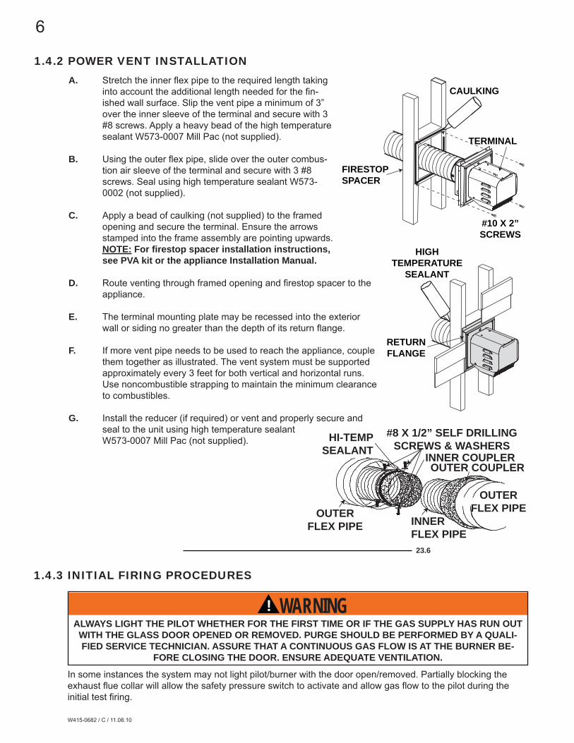
1.4.2 POWER VENT INSTALLATION
23.6
A. Stretch the inner fl ex pipe to the required length taking into account the additional length needed for the fi n-ished wall surface. Slip the vent pipe a minimum of 3” over the inner sleeve of the terminal and secure with 3 #8 screws. Apply a heavy bead of the high temperature sealant W573-0007 Mill Pac (not supplied).
B. Using the outer fl ex pipe, slide over the outer combus-tion air sleeve of the terminal and secure with 3 #8 screws. Seal using high temperature sealant W573-0002 (not supplied).
C. Apply a bead of caulking (not supplied) to the framed opening and secure the terminal. Ensure the arrows stamped into the frame assembly are pointing upwards. NOTE: For fi restop spacer installation instructions, see PVA kit or the appliance Installation Manual.
D. Route venting through framed opening and fi restop spacer to the appliance.
E. The terminal mounting plate may be recessed into the exterior wall or siding no greater than the depth of its return fl ange.
F. If more vent pipe needs to be used to reach the appliance, couple them together as illustrated. The vent system must be supported approximately every 3 feet for both vertical and horizontal runs. Use noncombustible strapping to maintain the minimum clearance to combustibles.
G. Install the reducer (if required) or vent and properly secure and seal to the unit using high temperature sealant W573-0007 Mill Pac (not supplied). HI-TEMP
SEALANT#8 X 1/2” SELF DRILLING
SCREWS & WASHERSINNER COUPLEROUTER COUPLER
OUTER FLEX PIPE INNER
FLEX PIPE
OUTER FLEX PIPE
TERMINAL
CAULKING
FIRESTOPSPACER
#10 X 2”SCREWS
HIGH TEMPERATURE
SEALANT
RETURN FLANGE
1.4.3 INITIAL FIRING PROCEDURES
! WARNINGALWAYS LIGHT THE PILOT WHETHER FOR THE FIRST TIME OR IF THE GAS SUPPLY HAS RUN OUT WITH THE GLASS DOOR OPENED OR REMOVED. PURGE SHOULD BE PERFORMED BY A QUALI-FIED SERVICE TECHNICIAN. ASSURE THAT A CONTINUOUS GAS FLOW IS AT THE BURNER BE-
FORE CLOSING THE DOOR. ENSURE ADEQUATE VENTILATION.
In some instances the system may not light pilot/burner with the door open/removed. Partially blocking the exhaust fl ue collar will allow the safety pressure switch to activate and allow gas fl ow to the pilot during the initial test fi ring.
7
W415-0682 / C / 11.08.10
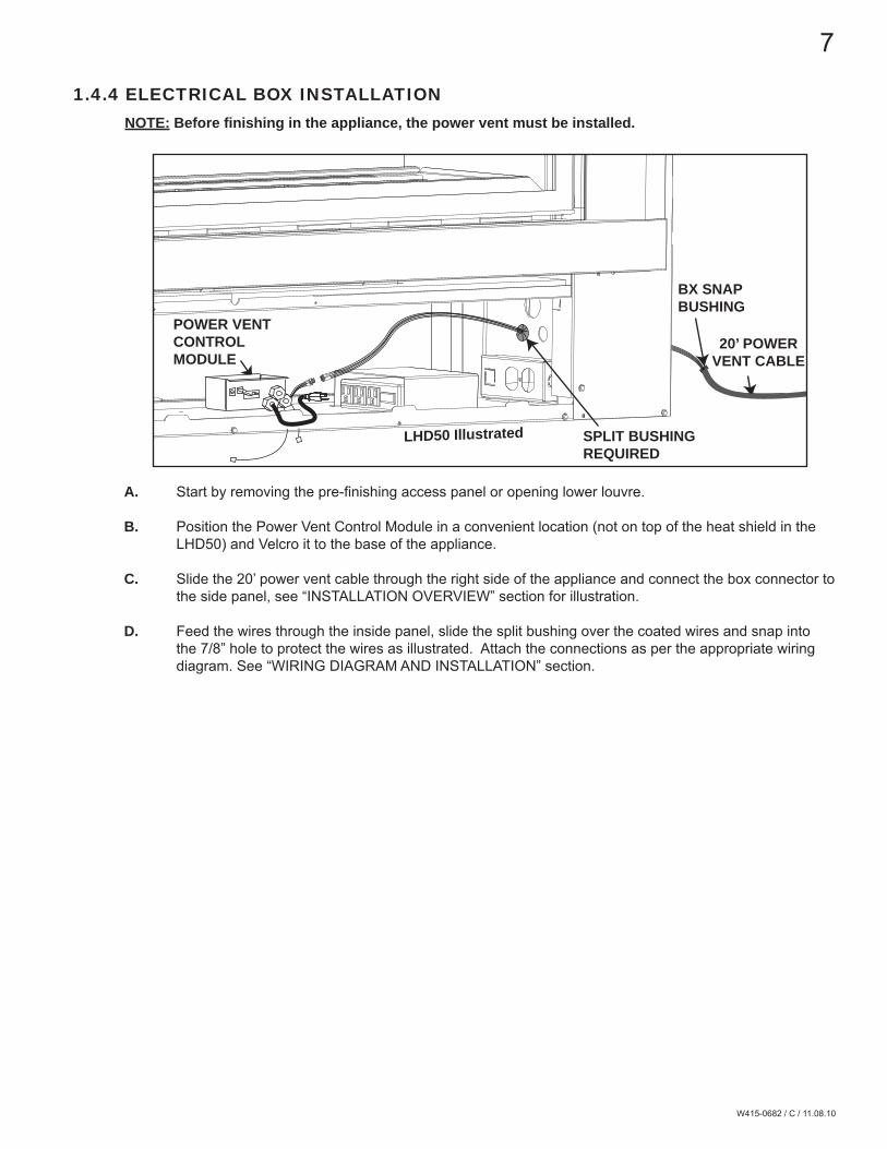
1.4.4 ELECTRICAL BOX INSTALLATIONNOTE: Before fi nishing in the appliance, the power vent must be installed.
A. Start by removing the pre-fi nishing access panel or opening lower louvre.
B. Position the Power Vent Control Module in a convenient location (not on top of the heat shield in the LHD50) and Velcro it to the base of the appliance.
C. Slide the 20’ power vent cable through the right side of the appliance and connect the box connector to the side panel, see “INSTALLATION OVERVIEW” section for illustration.
D. Feed the wires through the inside panel, slide the split bushing over the coated wires and snap into the 7/8” hole to protect the wires as illustrated. Attach the connections as per the appropriate wiring diagram. See “WIRING DIAGRAM AND INSTALLATION” section.
POWER VENT CONTROL MODULE
BX SNAP BUSHING
LHD50 Illustrated
20’ POWER VENT CABLE
SPLIT BUSHINGREQUIRED
8
W415-0682 / C / 11.08.10
1.5 RESTRICTOR PLATE INSTALLATION
1.6 WIRING DIAGRAM AND INSTALLATIONConnect the wiring to the power vent termination as outlined in the previous section, and connect the wiring to the appliance as outlined in the schematic below. Ensure that the proper clearances are maintained for the wiring and conduit. When installing the wiring it must never run above the vent run and it must be a minimum 1” from all venting.
NOTE: The GPV includes a 20 foot wire harness. If this harness does not reach the appliance, then it may be cut and a splice added. These connections must conform with local codes or, in the absence of local codes, use the current CSA C22.1 Canadian Electrical Code in Canada or the ANSI/NFPA 70 National Electrical Code in the United States.
REFER TO PVA KIT FOR APPLIANCE SPECIFIC INSTRUCTIONS.
1.6.1 SIT IPI 885 PROFLAME COMPLETE WITH GPV POWER VENT TERMINAL
1. Disconnect the wires labeled ON/OFF (White/Green) and TH (Green). Reconnect them to the corresponding male/female connectors on the Power vent control module.
2. Disconnect the two D/C (Red/Black) wires from each other and reconnect them to the corresponding D/C connectors on the Power vent control module.
3. Disconnect the Orange wire from the gas valve and reconnect it to the Yellow wire (female connector) from the Power vent control module.
4. Connect the remaining Yellow wire (male connector) from the Power vent control module to the tab on the gas valve where the Orange wire was removed.

9
W415-0682 / C / 11.08.10
IPI B
oard
SPA
RK
E
LEC
TRO
DE
FLA
ME
S
EN
SO
R
SIT
Val
veE
lect
roni
c Ig
nitio
n
BLA
CK
3/1
6 C
ON
NE
CTI
ON
BLA
CK
1/8
C
ON
NE
CTI
ON
TUB
E
GR
EE
NO
RA
NG
EYELLOW / GREEN
YE
LLO
W /
GR
EE
N
IPI /
CP
I (A
CS
) S
WIT
CH
(OP
TIO
NA
L)
RED / FCM-COM
BLUEPINK
BLACK
WH
ITE
/ TP
THB
LAC
K /
DC
SU
PP
LYR
ED
/ D
C S
UP
PLY
GREY / FCM-COMPURPLE / FCM-COM
COM
120 VOLT FAN AUX OUT
ORANGE / MOTORYELLOW / MOTORBLACK / MOTORBROWN / MOTOR
WH
ITE
Rec
eive
r
Con
trol
Mod
ulePOWER
Pilo
t Ass
embl
y
WH
ITE
/ G
RE
EN
/ O
N/O
FF
BLA
CK
RE
DIM
PORT
ANT:
IF U
SED,
IT
MUS
T BE
CO
NNEC
TED
TO A
6
VOLT
BAT
TERY
PAC
K,
HOW
EVER
MUS
T NO
T BE
USE
D W
HEN
USIN
G
THE
REM
OTE
CO
NTRO
L RE
CEIV
ER
PLU
GIN
TO12
0 V
OLT
Pow
er
Vent
C
ontro
l M
odul
e
BLACKWHITE
YE
LLO
WY
ELL
OW
BLO
WE
R
VAC
SW
ITC
H
GREEN GP
V T
erm
inal
SP
LIT
FLO
W
(IF IN
CLU
DE
D
WIT
H A
PP
LIA
NC
E)
GR
EE
N /
TH
BLA
CK
/ D
C S
UP
PLY
RE
D /
DC
SU
PP
LY
Pul
l con
nect
ors
apar
t to
conn
ect t
o po
wer
ven
t
YE
LLO
WY
ELL
OW
1
2
3
4

10
W415-0682 / C / 11.08.10
1.6.2 SIT MILLIVOLT 820 NOVA COMPLETE WITH GPV POWER VENT TERMINAL
PILOT BURNER
THERMOCOUPLE
THERMOPILE
RED
WHITE
BLA
CK
WH
ITE
OR
AN
GE
RE
D
YELLOWYELLOW
GREEN
Pilot Assembly
SIT Millivolt Gas Valve
Double Pole Switch
BLA
CK
WH
ITE
YELLOWYELLOW
BLOWER
VAC SWITCH
GR
EE
N
GPV Terminal
Power Vent Control Module
Appliance Junction Box
JUM
PE
R
2
1
NOTE: Must use double pole switch (supplied) or double pole thermostat (not supplied) with specifi c power vent adaptor kit.
1. Connect the jumper wire to tabs 1 and 3 on the gas valve.2. Connect the jumper wire to the two Yellow wires from the Power vent control module.
11
W415-0682 / C / 11.08.10
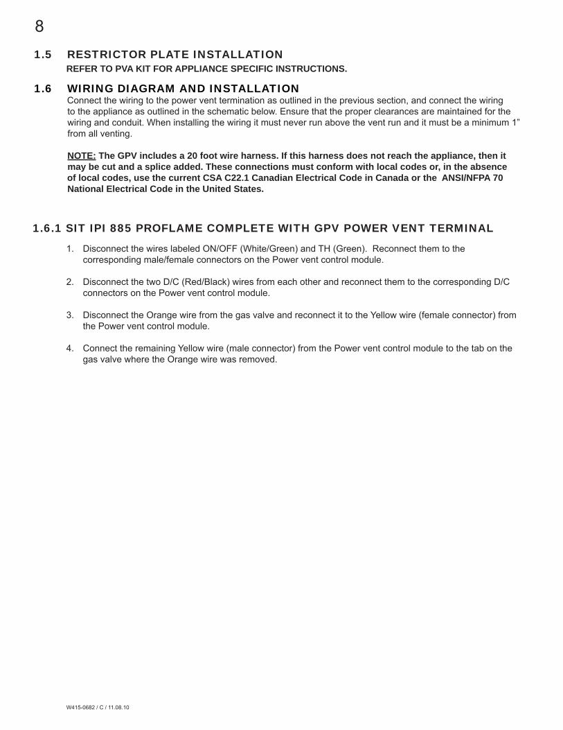
1.6.3 SIT IPI 880/886 PROFLAME COMPLETE WITH GPV POWER VENT TERMINAL
ACS/IPI SWITCH
(OPTIONAL)
DC BACK-UP(NOT ALLOWED
WITH GPV INSTALLATION)
GROUND
DFC
VALVE
ORANGEGREEN
GROUND EYELET
IPI / CPI
+
+
-
-
IPI BOARD
DC SUPPLY
TRANSFORMER
VALVE ELECTRONIC
BLA
CK
WH
ITE
OR
AN
GE
RE
D
GREEN
Power Vent
Control Module
Appliance Junction Box
BLA
CK
WH
ITE
YELLOWYELLOW
BLOWER
VAC SWITCH
GR
EE
N
GPV Terminal
Double Pole Switch
YELLOWYELLOW
JUM
PE
R
2
1
NOTE: Must use double pole switch (supplied) or double pole thermostat (not supplied) with specifi c power vent adaptor kit.
1. Connect the jumper wires to the wire labeled ON/OFF (Green/White) and the wire labelled TH (Green).2. Connect the other end of the jumper wires to the Yellow wires from the Power vent control module.
12
W415-0682 / C / 11.08.10
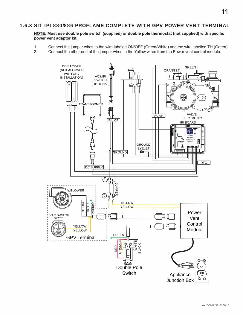
1.6.4 DEXEN IPI 6003-3V COMPLETE WITH GPV POWER VENT TERMINALNOTE: Must use double pole switch (supplied) or double pole thermostat (not supplied) with specifi c power vent adaptor kit.
1. Connect the Brown wires from the Ignition module to the yellow wires from the Power vent control module.
Dexen Gas Valve
Ignition Module
Battery Holder
Battery Relay
ORANGE
YELLOW
GREEN
BLACK
ORANGE
BLU
E
RE
D
BROWNBROWN
BLU
E
BLA
CK
YELLOWYELLOW
BLA
CK
WH
ITE
OR
AN
GE
RE
D
GREEN
Ignitor
Power Vent
Control Module
Appliance Junction Box
BLA
CK
YELLOWB
LAC
KW
HITE
YELLOWYELLOW
BLOWER
VAC SWITCH
GR
EE
N
GPV Terminal
Double Pole Switch
1
13
W415-0682 / C / 11.08.10
2.1 VENTURI ADJUSTMENTS
2.0 ADJUSTMENTS
REFER TO PVA KIT FOR SPECIFIC APPLIANCE INSTRUCTIONS.
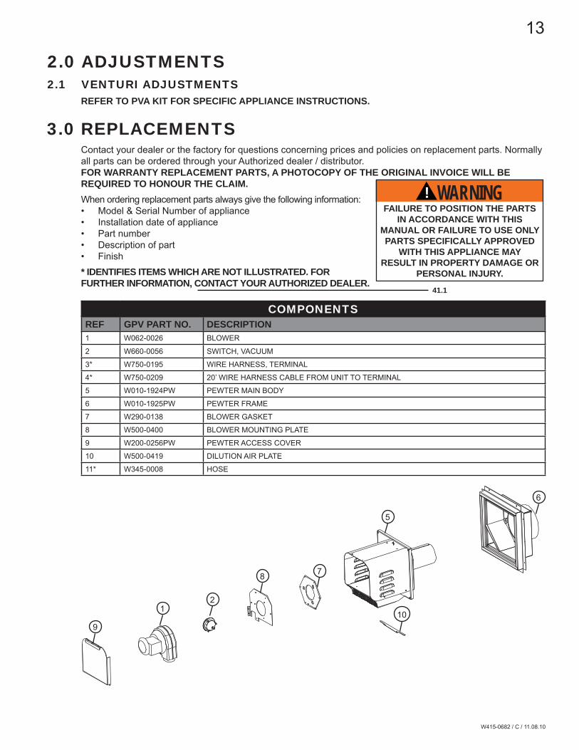
3.0 REPLACEMENTSContact your dealer or the factory for questions concerning prices and policies on replacement parts. Normally all parts can be ordered through your Authorized dealer / distributor. FOR WARRANTY REPLACEMENT PARTS, A PHOTOCOPY OF THE ORIGINAL INVOICE WILL BE REQUIRED TO HONOUR THE CLAIM.When ordering replacement parts always give the following information:• Model & Serial Number of appliance• Installation date of appliance• Part number• Description of part• Finish* IDENTIFIES ITEMS WHICH ARE NOT ILLUSTRATED. FOR FURTHER INFORMATION, CONTACT YOUR AUTHORIZED DEALER.
41.1
FAILURE TO POSITION THE PARTS IN ACCORDANCE WITH THIS
MANUAL OR FAILURE TO USE ONLY PARTS SPECIFICALLY APPROVED
WITH THIS APPLIANCE MAY RESULT IN PROPERTY DAMAGE OR
PERSONAL INJURY.
! WARNING
COMPONENTSREF GPV PART NO. DESCRIPTION1 W062-0026 BLOWER
2 W660-0056 SWITCH, VACUUM
3* W750-0195 WIRE HARNESS, TERMINAL
4* W750-0209 20’ WIRE HARNESS CABLE FROM UNIT TO TERMINAL
5 W010-1924PW PEWTER MAIN BODY
6 W010-1925PW PEWTER FRAME
7 W290-0138 BLOWER GASKET
8 W500-0400 BLOWER MOUNTING PLATE
9 W200-0256PW PEWTER ACCESS COVER
10 W500-0419 DILUTION AIR PLATE
11* W345-0008 HOSE
21
9
8 7
10
5
6

14
W415-0682 / C / 11.08.10
SYMPTOM PROBLEM TEST SOLUTIONMain burner fl ame is a blue lazy transpar-ent fl ame.
Leak in exhaust vent. - Check exhaust vent pipe and all connection seals.Incorrect installation. - Refer to PVA kit for appliance specifi c restrictor.
Carbon is being deposited on glass or combustion chamber surfaces.
Air shutter has become blocked or incorrect setting.
- Ensure air shutter opening is free of lint or other obstructions or has correct setting.
Flame is impinging on the logs or combustion chamber.
- Check that the media is correctly positioned.- Open air shutter to increase the primary air.- Check the input rate: Check the manifold pressure and orifi ce size as specifi ed by the rating plate values.
- Check that the door gasket is not broken or missing and that the seal is tight.
- Check that both 4" and 7" vent liners are free of holes and well sealed at all joints.
- Check that the proper restrictor is usedWhite / Grey fi lm forms.
Sulphur from fuel is being de-posited on glass, logs or com-bustion chamber surfaces.
- Clean the glass with a gas appliance glass cleaner. DO NOT CLEAN GLASS WHEN HOT.
- If deposits are not cleaned off regularly, the glass may become permanently marked.
Exhaust fumes smelled in room, headaches.
Fireplace is spilling. - Check door seal and relief fl ap seal.- Check for proper restrictor.- Check that the paint curing process is complete.
Main burner will not light.
Main door is not installed. - Install main door.
Main burner fl ames are very aggressive.
No restrictor. - Add restrictor.
Main burner won’t light.
Vacuum switch not activated. - Remove blockage. In really cold conditions, ice buildup may occur on the terminal and should be removed as required.
- Test vacuum switch and replace as required.
4.0 TROUBLE SHOOTING
IMPORTANT: Prove all systems check before completely enclosing unit.
! WARNINGALWAYS LIGHT THE PILOT WHETHER FOR THE FIRST TIME OR IF THE GAS SUPPLY HAS RAN OUT,
WITH THE GLASS DOOR OPEN OR REMOVED.IN SOME INSTANCES THE SYSTEM MAY NOT LIGHT PILOT/BURNER WITH THE DOOR OPEN/REMOVED. PARTIALLY BLOCKING THE EXHAUST FLUE COLLAR WILL ALLOW THE SAFETY
PRESSURE SWITCH TO ACTIVATE AND ALLOW GAS FLOW TO THE PILOT DURING THE INITIAL TEST FIRING.

15
W415-0682 / C / 11.08.10
44.1
5.0 NOTES

16
W415-0682 / C / 11.08.10
44.1


![Scholarship Directory[1] Afro American Canadian Carribean](https://img.pdfslide.net/doc/110x75/577ce31d1a28abf1038b5a55/scholarship-directory1-afro-american-canadian-carribean.jpg)

