Embed Size (px)
Citation preview

Cessna 150 Aerobat 250 ARFAssembly Manual
2 E-flite Cessna 150 Aerobat 250 ARF Assembly Manual
Notice
All instructions, warranties and other collateral documents are subject to change at the sole
discretion of Horizon Hobby, Inc. For up-to-date product literature, visit http://www.horizonhobby.com and click on the support tab for this product.
Meaning of Special Language
The following terms are used throughout the product literature to indicate various levels of potential harm
when operating this product:
NOTICE: Procedures, which if not properly followed, create a possibility of physical property damage
AND a little or no possibility of injury.
CAUTION: Procedures, which if not properly followed, create the probability of physical property damage
AND a possibility of serious injury.
WARNING: Procedures, which if not properly followed, create the probability of property damage, collateral
damage, and serious injury OR create a high probability of superficial injury.
WARNING: Read the ENTIRE instruction manual to become familiar with the features of the product before operating. Failure to operate the
product correctly can result in damage to the product, personal property and cause serious injury.
This is a sophisticated hobby product and NOT a toy. It must be operated with caution and common
sense and requires some basic mechanical ability. Failure to operate this Product in a safe
and responsible manner could result in injury or damage to the product or other property. This
product is not intended for use by children without direct adult supervision. Do not attempt disassembly,
use with incompatible components or augment product in any way without the approval of Horizon
Hobby, Inc. This manual contains instructions for safety, operation and maintenance. It is essential to read and follow all the instructions and warnings in the manual, prior to assembly, setup or use, in order to operate correctly and avoid damage or
serious injury.
Warnings
Read and follow all instructions and safety precautions before use. Improper use can result in fire, serious injury and damage to property.
Age Recommendation: Not for children under 14 years. This is not a toy.
COMpONENTS
Use only with compatible components. Should any compatibility questions exist, please refer to the product instructions, the component instructions or contact Horizon Hobby, Inc.
FLIGhT
Fly only in open areas to ensure safety. It is recommended flying be done at AMA (Academy of Model Aeronautics) approved flying sites. Consult local laws and ordinances before choosing a location to fly your aircraft.
pROpELLER
Keep loose items that can get entangled in the propeller away from the prop, including loose clothing or other objects such as pencils and screwdrivers. Especially keep your hands away from the propeller as injury can occur.
BATTERIES
Notes on Lithium polymer Batteries
When misused, lithium polymer batteries are significantly more volatile than alkaline or Ni-Cd/Ni-MH batteries used in RC applications. Always follow the manufacturer’s instructions when using and disposing of any batteries. Mishandling of Li-Po batteries can result in fire causing serious injury and damage.
SMALL pARTS
This kit includes small parts and should not be left unattended near children as choking and serious injury could result.
SAFETy pRECAUTIONS
• Checkallcontrolsurfacespriortoeachtakeoff.
• Donotflyyourmodelnearspectators,parkingareasor any other area that could result in injury to people or damage of property.
• Donotflyduringadverseweatherconditions.Poor visibility and/or strong winds can cause disorientation and loss of control of your aircraft.
• Donottakechances.Ifatanytimeduringflightyouobserve any erratic or abnormal operation, land immediately and do not resume flight until the cause of the problem has been ascertained and corrected. Safety can never be taken lightly.
• Donotflynearpowerlines.
3E-flite Cessna 150 Aerobat 250 ARF Assembly Manual
Important Information Regarding Warranty Information
Please read our Warranty and Liability Limitations section before building this product. If you as the Purchaser or user are not prepared to accept the liability associated with the use of this Product, you are advised to return this Product immediately in new and unused condition to the place of purchase.
SpecificationsWingspan: 37.9 in (960mm)Length: 27.2 in (690mm)Wing Area: 196 sq in (12.6 sq dm)Weight with battery: 12.0–13.7 oz
(340–388 g)Weight w/o battery: 10.9–12.2 oz
(309–346 g)
Using the Manual
This manual is divided into sections to help make assembly easier to understand and to provide breaks between each major section. In addition, check boxes have been placed next to each step to keep track of its completion. Steps with a single circle () are performed once, while steps with two or more circles () indicate the step will require repeating, such as for a right or left wing panel, two servos, etc.
Remember to take your time and follow the directions.
Introduction
The Cessna 150, while designed over 50 years ago, to this day has a personality and spirit all its own. Considered still tame enough for training, the Aerobat version appealed to casual pilots that needed a jolt to become even more proficient. This 250-size ARF version is for RC pilots wanting the thrill of basic aerobatics in a small yet detailed package. This clever, all-wood model remarkably maintains the subtle curves and character of the original aircraft, yet is distinctively detailed with a checker-scheme that honors the character of the Aerobat. Despite its compact size, you get these great features like an: authentic scale outline, laser cut engineering, fiberglass cowl and wheel pants, and a lightweight UltraCote® ParkLite™ trim scheme. The magnetically secured wing panels and cowling make for quick assembly and the oversized quick-release accessory hatch allows easy access for radio and battery installation. The steerable nose strut makes ground handling a breeze and the optional aluminum spinner (EFLSP100) adds the perfect finish to the model.
Table of ContentsNotice ...................................................................... 2Meaning of Special Language ................................... 2Warnings ................................................................. 2Introduction .............................................................. 3Important Information Regarding
Warranty Information ....................................... 3Specifications ........................................................... 3Using the Manual ..................................................... 3Contents of Kit/Parts Layout ...................................... 4Covering Colors ........................................................ 4Hardware/Accessory Sizes ....................................... 4Recommended Radio Equipment ................................ 4Park 250 Motor Setup ............................................... 4Park 280 Motor Setup ............................................... 4Optional Accessories ................................................ 4Required Tools and Adhesives ................................... 4Before Starting Assembly .......................................... 5Aileron Servo Installation .......................................... 5Rudder and Elevator Servo Installation ....................... 8Landing Gear Installation ........................................10Motor and Speed Control Installation .......................14Receiver Installation.................................................15Horizontal Stabilizer Installation ..............................16Vertical Stabilizer Installation ...................................19Rudder, Elevator and Nose Gear
Linkage Installation .........................................21Windscreen, Wing and Wing Strut Installation .........23Motor Battery, Cowl, Propeller and
Spinner Installation .........................................25Decal Installation ....................................................27Center of Gravity ....................................................27Control Throws .......................................................28Preflight ..................................................................28Range Test Your Radio .............................................29Flying Your Model ...................................................29Daily Flight Checks .................................................29Limited Warranty ....................................................30Warranty Services ..................................................30Compliance Information for the European Union ......31Academy of Model Aeronautics
National Model Aircraft Safety Code ..............32Building and Flying Notes ................................. 33–34
4 E-flite Cessna 150 Aerobat 250 ARF Assembly Manual
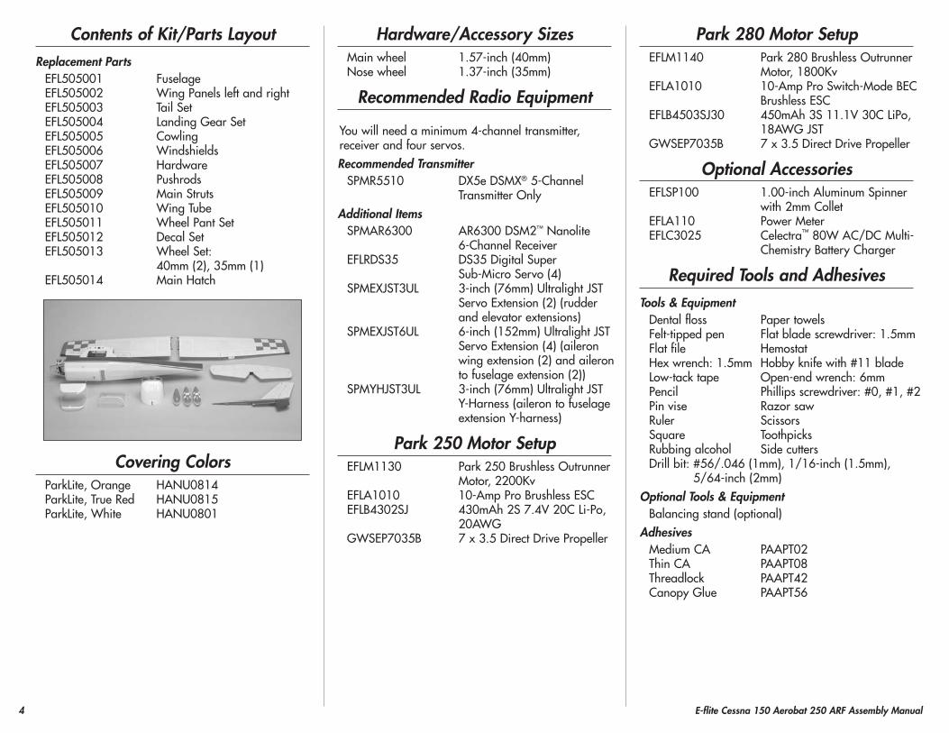
Contents of Kit/parts LayoutReplacement parts
EFL505001 FuselageEFL505002 Wing Panels left and rightEFL505003 Tail SetEFL505004 Landing Gear SetEFL505005 CowlingEFL505006 WindshieldsEFL505007 HardwareEFL505008 PushrodsEFL505009 Main StrutsEFL505010 Wing TubeEFL505011 Wheel Pant SetEFL505012 Decal Set EFL505013 Wheel Set:
40mm (2), 35mm (1)EFL505014 Main Hatch
Covering ColorsParkLite, Orange HANU0814ParkLite, True Red HANU0815ParkLite, White HANU0801
hardware/Accessory SizesMain wheel 1.57-inch (40mm)Nose wheel 1.37-inch (35mm)
Recommended Radio Equipment
You will need a minimum 4-channel transmitter, receiver and four servos.Recommended Transmitter
SPMR5510 DX5e DSMX® 5-Channel Transmitter Only
Additional ItemsSPMAR6300 AR6300 DSM2™ Nanolite
6-Channel ReceiverEFLRDS35 DS35 Digital Super
Sub-Micro Servo (4)SPMEXJST3UL 3-inch (76mm) Ultralight JST
Servo Extension (2) (rudder and elevator extensions)
SPMEXJST6UL 6-inch (152mm) Ultralight JST Servo Extension (4) (aileron wing extension (2) and aileron to fuselage extension (2))
SPMYHJST3UL 3-inch (76mm) Ultralight JST Y-Harness (aileron to fuselage extension Y-harness)
park 250 Motor SetupEFLM1130 Park 250 Brushless Outrunner
Motor, 2200KvEFLA1010 10-Amp Pro Brushless ESCEFLB4302SJ 430mAh 2S 7.4V 20C Li-Po,
20AWGGWSEP7035B 7 x 3.5 Direct Drive Propeller
park 280 Motor SetupEFLM1140 Park 280 Brushless Outrunner
Motor, 1800KvEFLA1010 10-Amp Pro Switch-Mode BEC
Brushless ESCEFLB4503SJ30 450mAh 3S 11.1V 30C LiPo,
18AWG JSTGWSEP7035B 7 x 3.5 Direct Drive Propeller
Optional AccessoriesEFLSP100 1.00-inch Aluminum Spinner
with 2mm ColletEFLA110 Power MeterEFLC3025 Celectra™ 80W AC/DC Multi-
Chemistry Battery Charger
Required Tools and AdhesivesTools & Equipment
Dental floss Paper towelsFelt-tipped pen Flat blade screwdriver: 1.5mmFlat file HemostatHex wrench: 1.5mm Hobby knife with #11 bladeLow-tack tape Open-end wrench: 6mmPencil Phillips screwdriver: #0, #1, #2Pin vise Razor sawRuler ScissorsSquare ToothpicksRubbing alcohol Side cuttersDrill bit: #56/.046 (1mm), 1/16-inch (1.5mm),
5/64-inch (2mm)Optional Tools & Equipment
Balancing stand (optional)Adhesives
Medium CA PAAPT02Thin CA PAAPT08Threadlock PAAPT42Canopy Glue PAAPT56
5E-flite Cessna 150 Aerobat 250 ARF Assembly Manual
Before Starting Assembly
Before beginning the assembly of your model, remove each part from its bag for inspection. Closely inspect the fuselage, wing panels, rudder and stabilizer for damage. If you find any damaged or missing parts, contact the place of purchase.
If you find any wrinkles in the covering, use a heat gun (HAN100) and covering glove (HAN150) or covering iron (HAN101) with a sealing iron sock (HAN141) to remove them. Use caution while working around seams or areas where the colors overlap to prevent pulling the seams.
During the course of building your model, we suggest you use a soft base for the building surface.
Such things as a foam stand, large piece of bedding foam or a thick bath towel will work well and help protect the model from damage during
assembly. This is not shown in the instructions to provide the greatest detail in the photos.
When referencing directions (up, down, left, right, top and bottom), take note that these are in relationship to the pilot sitting in the cockpit
of the aircraft unless noted otherwise.
Aileron Servo InstallationRequired parts
Wing panel (right and left)Transmitter ReceiverReceiver battery Servo with accessories (2)2mm x 5mm self-tapping screw (8)Aileron pushrod, 2.75-inch (78mm) (2)6-inch (152mm) servo extension (2)Pushrod connector with hardware (2)
Required Tools and AdhesivesMedium CA Phillips screwdriver: #0, #1Pin vise Thin CAPencil Dental flossToothpicks Side cuttersDrill bit: 1/16-inch (1.5mm), 5/64-inch (2mm)
1. Use the radio system to center the aileron servos. Use a # 0 Phillips screwdriver to center both of the stock arms so they are centered perpendicular to the servo. Make one of each shown for the left and right wing. Attach the mounting bracket to the servos as shown.
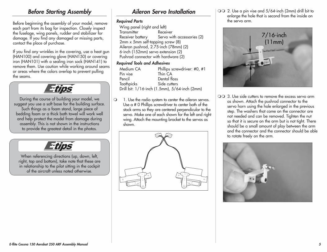
2. Use a pin vise and 5/64-inch (2mm) drill bit to enlarge the hole that is second from the inside on the servo arm.
3. Use side cutters to remove the excess servo arm as shown. Attach the pushrod connector to the servo horn using the hole enlarged in the previous step. The washers that come on the connector are not needed and can be removed. Tighten the nut so that it is secure on the arm but is not tight. There should be a small amount of play between the arm and the connector and the connector should be able to rotate freely on the arm.
6 E-flite Cessna 150 Aerobat 250 ARF Assembly Manual
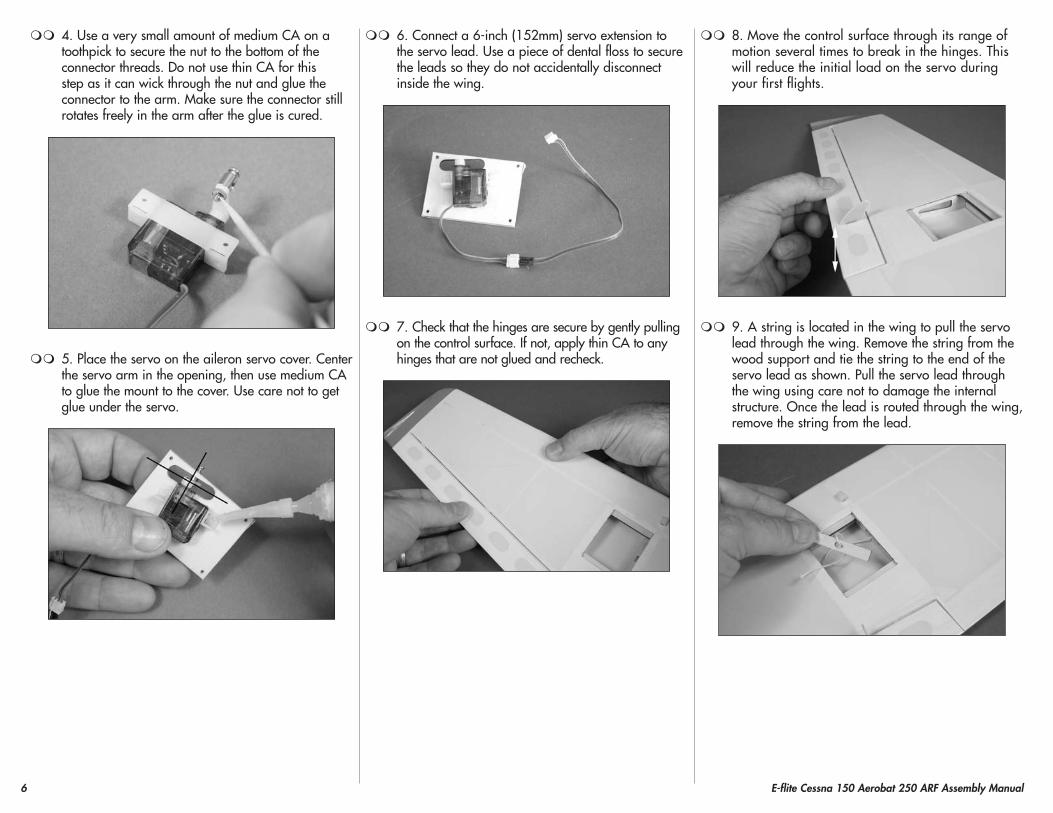
4. Use a very small amount of medium CA on a toothpick to secure the nut to the bottom of the connector threads. Do not use thin CA for this step as it can wick through the nut and glue the connector to the arm. Make sure the connector still rotates freely in the arm after the glue is cured.
5. Place the servo on the aileron servo cover. Center the servo arm in the opening, then use medium CA to glue the mount to the cover. Use care not to get glue under the servo.
6. Connect a 6-inch (152mm) servo extension to the servo lead. Use a piece of dental floss to secure the leads so they do not accidentally disconnect inside the wing.
7. Check that the hinges are secure by gently pulling on the control surface. If not, apply thin CA to any hinges that are not glued and recheck.
8. Move the control surface through its range of motion several times to break in the hinges. This will reduce the initial load on the servo during your first flights.
9. A string is located in the wing to pull the servo lead through the wing. Remove the string from the wood support and tie the string to the end of the servo lead as shown. Pull the servo lead through the wing using care not to damage the internal structure. Once the lead is routed through the wing, remove the string from the lead.
7E-flite Cessna 150 Aerobat 250 ARF Assembly Manual
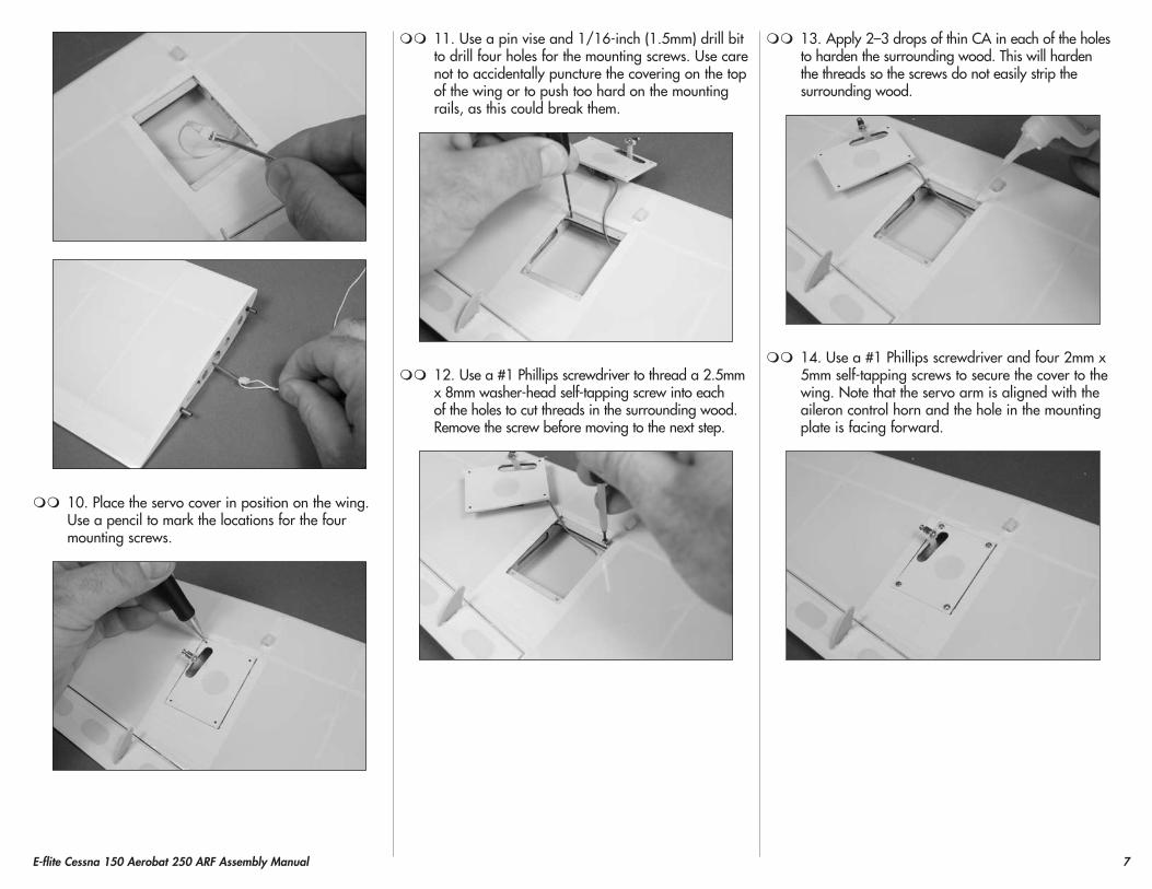
10. Place the servo cover in position on the wing. Use a pencil to mark the locations for the four mounting screws.
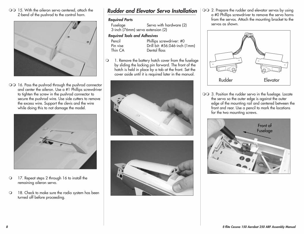
11. Use a pin vise and 1/16-inch (1.5mm) drill bit to drill four holes for the mounting screws. Use care not to accidentally puncture the covering on the top of the wing or to push too hard on the mounting rails, as this could break them.
12. Use a #1 Phillips screwdriver to thread a 2.5mm x 8mm washer-head self-tapping screw into each of the holes to cut threads in the surrounding wood. Remove the screw before moving to the next step.
13. Apply 2–3 drops of thin CA in each of the holes to harden the surrounding wood. This will harden the threads so the screws do not easily strip the surrounding wood.
14. Use a #1 Phillips screwdriver and four 2mm x 5mm self-tapping screws to secure the cover to the wing. Note that the servo arm is aligned with the aileron control horn and the hole in the mounting plate is facing forward.
8 E-flite Cessna 150 Aerobat 250 ARF Assembly Manual
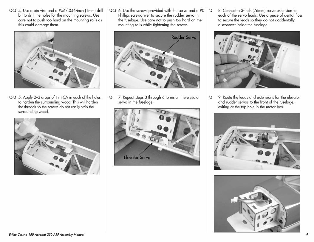
15. With the aileron servo centered, attach the Z-bend of the pushrod to the control horn.
16. Pass the pushrod through the pushrod connector and center the aileron. Use a #1 Phillips screwdriver to tighten the screw in the pushrod connector to secure the pushrod wire. Use side cutters to remove the excess wire. Support the clevis and the wire while doing this to not damage the model.
17. Repeat steps 2 through 16 to install the remaining aileron servo.
18. Check to make sure the radio system has been turned off before proceeding.
Rudder and Elevator Servo InstallationRequired parts
Fuselage Servo with hardware (2)3-inch (76mm) servo extension (2)
Required Tools and AdhesivesPencil Phillips screwdriver: #0Pin vise Drill bit: #56.046-inch (1mm)Thin CA Dental floss
1. Remove the battery hatch cover from the fuselage by sliding the locking pin forward. The front of the hatch is held in place by a tab at the front. Set the cover aside until it is required later in the manual.
2. Prepare the rudder and elevator servos by using a #0 Phillips screwdriver to remove the servo horns from the servos. Attach the mounting bracket to the servos as shown.
Rudder Elevator
3. Position the rudder servo in the fuselage. Locate the servo so the outer edge is against the outer edge of the mounting rail and centered between the front and rear. Use a pencil to mark the locations for the two mounting screws.
9E-flite Cessna 150 Aerobat 250 ARF Assembly Manual
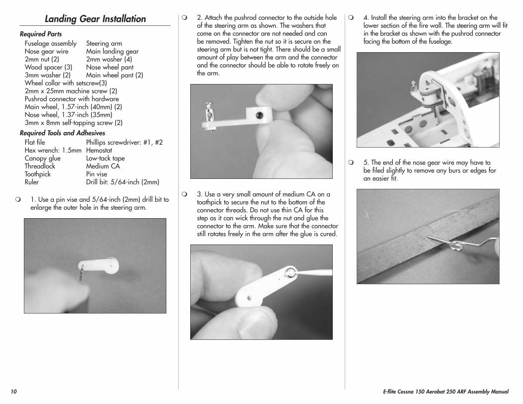
4. Use a pin vise and a #56/.046-inch (1mm) drill bit to drill the holes for the mounting screws. Use care not to push too hard on the mounting rails as this could damage them.
5. Apply 2–3 drops of thin CA in each of the holes to harden the surrounding wood. This will harden the threads so the screws do not easily strip the surrounding wood.
6. Use the screws provided with the servo and a #0 Phillips screwdriver to secure the rudder servo in the fuselage. Use care not to push too hard on the mounting rails while tightening the screws.
7. Repeat steps 3 through 6 to install the elevator servo in the fuselage.
8. Connect a 3-inch (76mm) servo extension to each of the servo leads. Use a piece of dental floss to secure the leads so they do not accidentally disconnect inside the fuselage.
9. Route the leads and extensions for the elevator and rudder servos to the front of the fuselage, exiting at the top hole in the motor box.
10 E-flite Cessna 150 Aerobat 250 ARF Assembly Manual
Landing Gear InstallationRequired parts
Fuselage assembly Steering armNose gear wire Main landing gear2mm nut (2) 2mm washer (4)Wood spacer (3) Nose wheel pant3mm washer (2) Main wheel pant (2)Wheel collar with setscrew(3)2mm x 25mm machine screw (2)Pushrod connector with hardwareMain wheel, 1.57-inch (40mm) (2)Nose wheel, 1.37-inch (35mm)3mm x 8mm self-tapping screw (2)
Required Tools and AdhesivesFlat file Phillips screwdriver: #1, #2Hex wrench: 1.5mm HemostatCanopy glue Low-tack tapeThreadlock Medium CAToothpick Pin vise Ruler Drill bit: 5/64-inch (2mm)
1. Use a pin vise and 5/64-inch (2mm) drill bit to enlarge the outer hole in the steering arm.
2. Attach the pushrod connector to the outside hole of the steering arm as shown. The washers that come on the connector are not needed and can be removed. Tighten the nut so it is secure on the steering arm but is not tight. There should be a small amount of play between the arm and the connector and the connector should be able to rotate freely on the arm.
3. Use a very small amount of medium CA on a toothpick to secure the nut to the bottom of the connector threads. Do not use thin CA for this step as it can wick through the nut and glue the connector to the arm. Make sure that the connector still rotates freely in the arm after the glue is cured.
4. Install the steering arm into the bracket on the lower section of the fire wall. The steering arm will fit in the bracket as shown with the pushrod connector facing the bottom of the fuselage.
5. The end of the nose gear wire may have to be filed slightly to remove any burs or edges for an easier fit.
11E-flite Cessna 150 Aerobat 250 ARF Assembly Manual
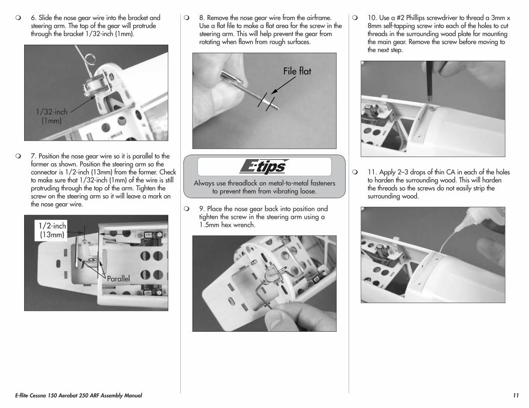
6. Slide the nose gear wire into the bracket and steering arm. The top of the gear will protrude through the bracket 1/32-inch (1mm).
7. Position the nose gear wire so it is parallel to the former as shown. Position the steering arm so the connector is 1/2-inch (13mm) from the former. Check to make sure that 1/32-inch (1mm) of the wire is still protruding through the top of the arm. Tighten the screw on the steering arm so it will leave a mark on the nose gear wire.
8. Remove the nose gear wire from the airframe. Use a flat file to make a flat area for the screw in the steering arm. This will help prevent the gear from rotating when flown from rough surfaces.
Always use threadlock on metal-to-metal fasteners to prevent them from vibrating loose.
9. Place the nose gear back into position and tighten the screw in the steering arm using a 1.5mm hex wrench.
10. Use a #2 Phillips screwdriver to thread a 3mm x 8mm self-tapping screw into each of the holes to cut threads in the surrounding wood plate for mounting the main gear. Remove the screw before moving to the next step.
11. Apply 2–3 drops of thin CA in each of the holes to harden the surrounding wood. This will harden the threads so the screws do not easily strip the surrounding wood.
12 E-flite Cessna 150 Aerobat 250 ARF Assembly Manual
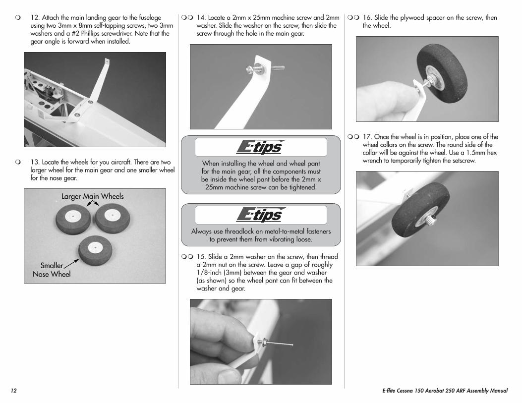
12. Attach the main landing gear to the fuselage using two 3mm x 8mm self-tapping screws, two 3mm washers and a #2 Phillips screwdriver. Note that the gear angle is forward when installed.
13. Locate the wheels for you aircraft. There are two larger wheel for the main gear and one smaller wheel for the nose gear.
14. Locate a 2mm x 25mm machine screw and 2mm washer. Slide the washer on the screw, then slide the screw through the hole in the main gear.
When installing the wheel and wheel pant for the main gear, all the components must be inside the wheel pant before the 2mm x
25mm machine screw can be tightened.
Always use threadlock on metal-to-metal fasteners to prevent them from vibrating loose.
15. Slide a 2mm washer on the screw, then thread a 2mm nut on the screw. Leave a gap of roughly 1/8-inch (3mm) between the gear and washer (as shown) so the wheel pant can fit between the washer and gear.
16. Slide the plywood spacer on the screw, then the wheel.
17. Once the wheel is in position, place one of the wheel collars on the screw. The round side of the collar will be against the wheel. Use a 1.5mm hex wrench to temporarily tighten the setscrew.
13E-flite Cessna 150 Aerobat 250 ARF Assembly Manual
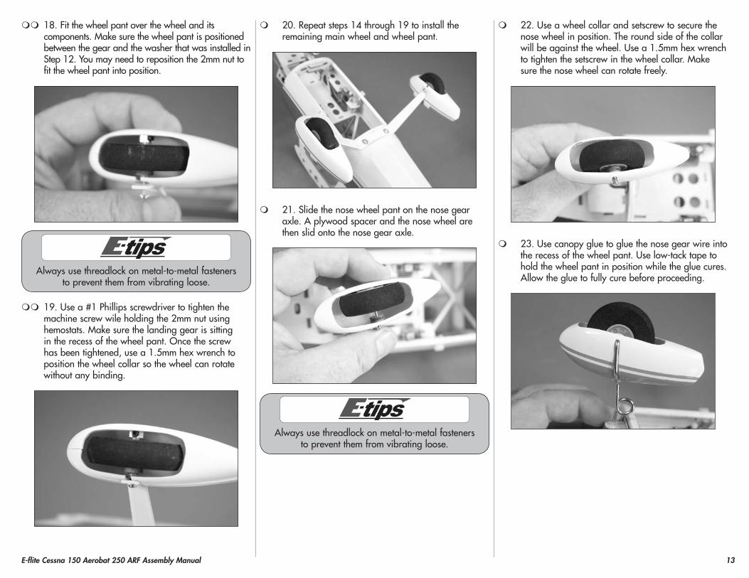
18. Fit the wheel pant over the wheel and its components. Make sure the wheel pant is positioned between the gear and the washer that was installed in Step 12. You may need to reposition the 2mm nut to fit the wheel pant into position.
Always use threadlock on metal-to-metal fasteners to prevent them from vibrating loose.
19. Use a #1 Phillips screwdriver to tighten the machine screw wile holding the 2mm nut using hemostats. Make sure the landing gear is sitting in the recess of the wheel pant. Once the screw has been tightened, use a 1.5mm hex wrench to position the wheel collar so the wheel can rotate without any binding.
20. Repeat steps 14 through 19 to install the remaining main wheel and wheel pant.
21. Slide the nose wheel pant on the nose gear axle. A plywood spacer and the nose wheel are then slid onto the nose gear axle.
Always use threadlock on metal-to-metal fasteners to prevent them from vibrating loose.
22. Use a wheel collar and setscrew to secure the nose wheel in position. The round side of the collar will be against the wheel. Use a 1.5mm hex wrench to tighten the setscrew in the wheel collar. Make sure the nose wheel can rotate freely.
23. Use canopy glue to glue the nose gear wire into the recess of the wheel pant. Use low-tack tape to hold the wheel pant in position while the glue cures. Allow the glue to fully cure before proceeding.
14 E-flite Cessna 150 Aerobat 250 ARF Assembly Manual
Motor and Speed Control InstallationRequired parts
Fuselage assembly Electronic speed controlHook and loop tape Tie-wrap (not included)
Required parts (park 250)Park 250 motor with accessories2mm x 10mm self-tapping screw (2)Plywood motor spacer
Required parts (park 280)Park 280 motor with accessories2mm x 6mm self-tapping screw (2)
Required Tools and AdhesivesThin CA Phillips screwdriver: #1Scissors Flat blade screwdriver: 1.5mm
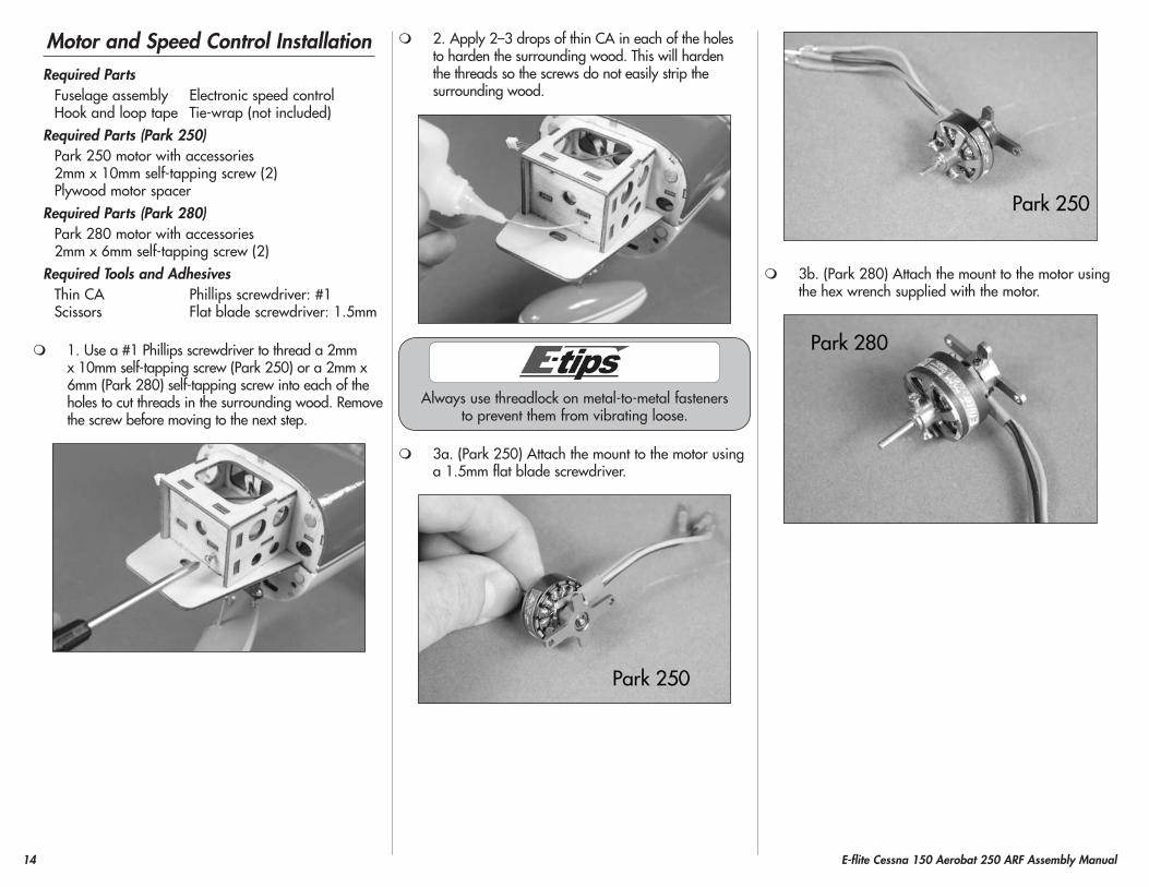
1. Use a #1 Phillips screwdriver to thread a 2mm x 10mm self-tapping screw (Park 250) or a 2mm x 6mm (Park 280) self-tapping screw into each of the holes to cut threads in the surrounding wood. Remove the screw before moving to the next step.
2. Apply 2–3 drops of thin CA in each of the holes to harden the surrounding wood. This will harden the threads so the screws do not easily strip the surrounding wood.
Always use threadlock on metal-to-metal fasteners to prevent them from vibrating loose.
3a. (Park 250) Attach the mount to the motor using a 1.5mm flat blade screwdriver.
3b. (Park 280) Attach the mount to the motor using the hex wrench supplied with the motor.
15E-flite Cessna 150 Aerobat 250 ARF Assembly Manual
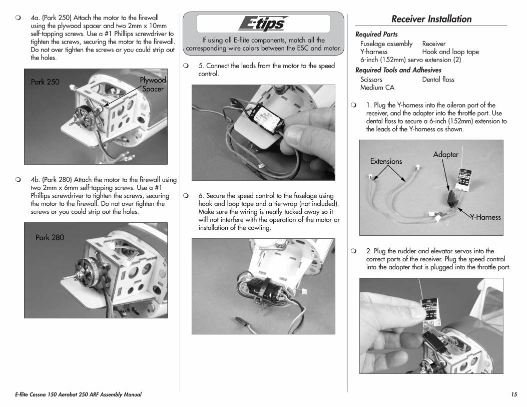
4a. (Park 250) Attach the motor to the firewall using the plywood spacer and two 2mm x 10mm self-tapping screws. Use a #1 Phillips screwdriver to tighten the screws, securing the motor to the firewall. Do not over tighten the screws or you could strip out the holes.
4b. (Park 280) Attach the motor to the firewall using two 2mm x 6mm self-tapping screws. Use a #1 Phillips screwdriver to tighten the screws, securing the motor to the firewall. Do not over tighten the screws or you could strip out the holes.
If using all E-flite components, match all the corresponding wire colors between the ESC and motor.
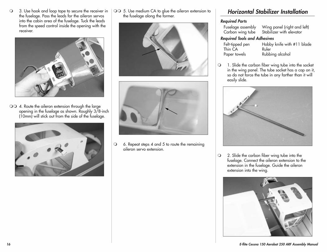
5. Connect the leads from the motor to the speed control.
6. Secure the speed control to the fuselage using hook and loop tape and a tie-wrap (not included). Make sure the wiring is neatly tucked away so it will not interfere with the operation of the motor or installation of the cowling.
Receiver InstallationRequired parts
Fuselage assembly ReceiverY-harness Hook and loop tape6-inch (152mm) servo extension (2)
Required Tools and AdhesivesScissors Dental flossMedium CA
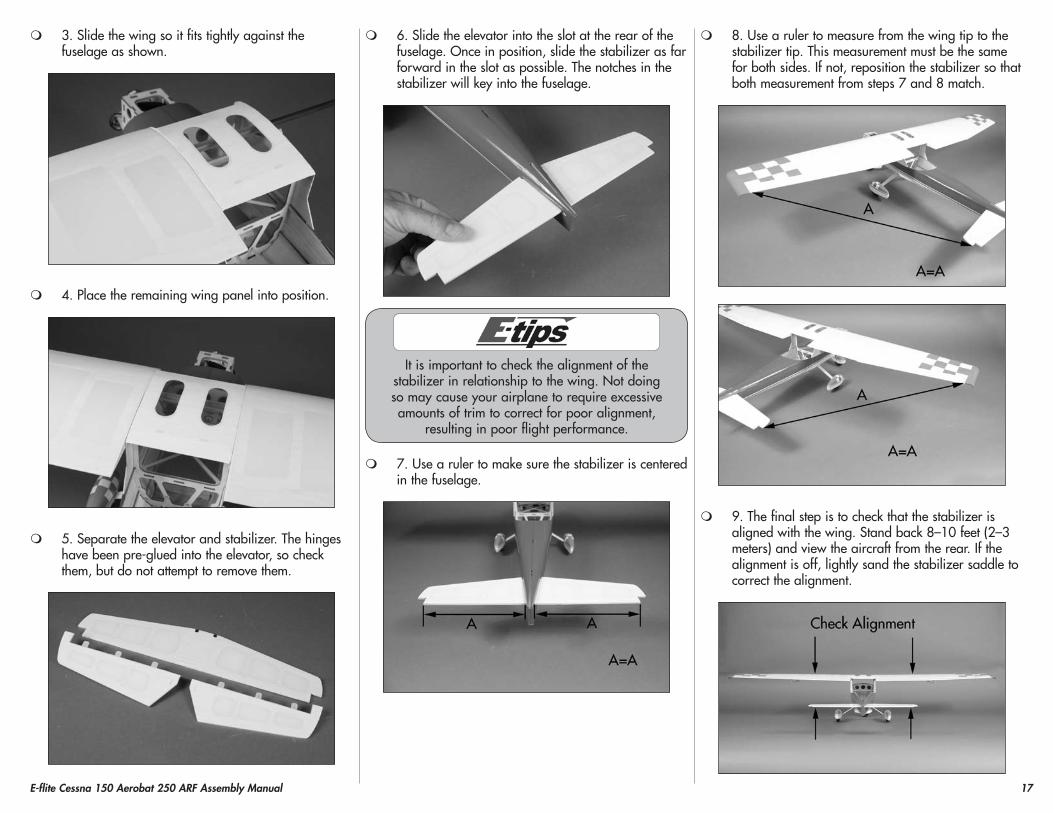
1. Plug the Y-harness into the aileron port of the receiver, and the adapter into the throttle port. Use dental floss to secure a 6-inch (152mm) extension to the leads of the Y-harness as shown.
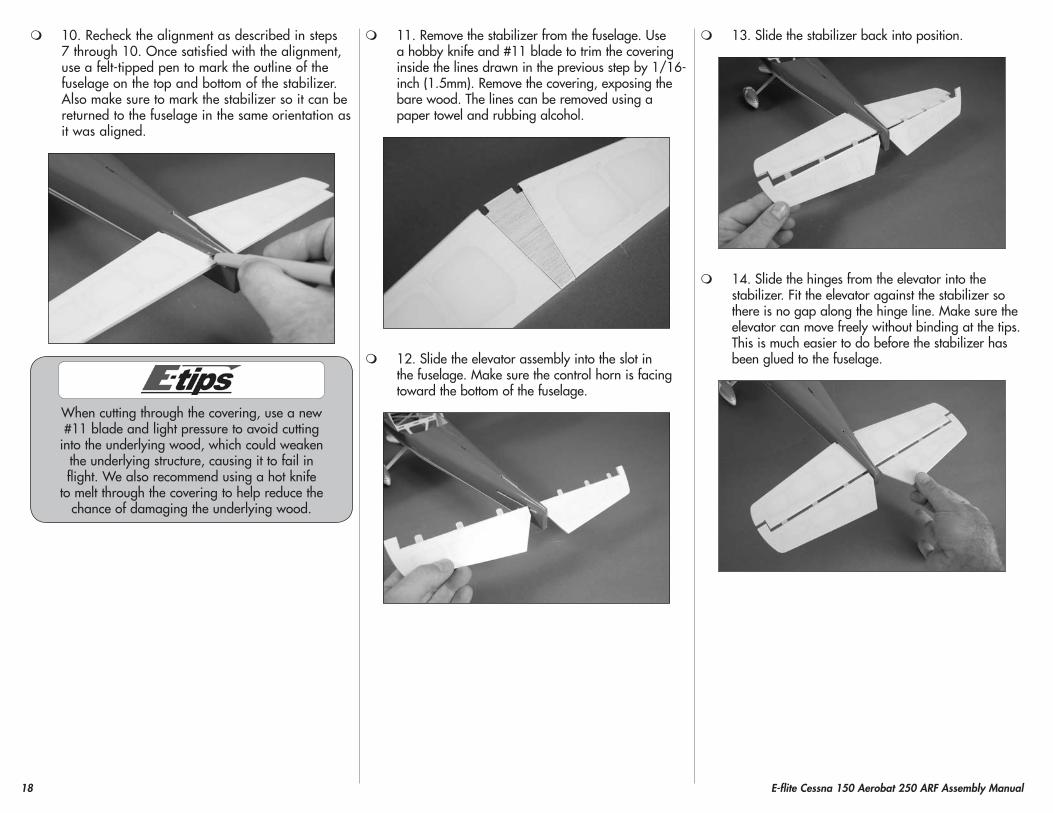
2. Plug the rudder and elevator servos into the correct ports of the receiver. Plug the speed control into the adapter that is plugged into the throttle port.
16 E-flite Cessna 150 Aerobat 250 ARF Assembly Manual
3. Use hook and loop tape to secure the receiver in the fuselage. Pass the leads for the aileron servos into the cabin area of the fuselage. Tuck the leads from the speed control inside the opening with the receiver.
4. Route the aileron extension through the large opening in the fuselage as shown. Roughly 3/8-inch (10mm) will stick out from the side of the fuselage.
5. Use medium CA to glue the aileron extension to the fuselage along the former.
6. Repeat steps 4 and 5 to route the remaining aileron servo extension.
horizontal Stabilizer InstallationRequired parts
Fuselage assembly Wing panel (right and left)Carbon wing tube Stabilizer with elevator
Required Tools and AdhesivesFelt-tipped pen Hobby knife with #11 bladeThin CA RulerPaper towels Rubbing alcohol
1. Slide the carbon fiber wing tube into the socket in the wing panel. The tube socket has a cap on it, so do not force the tube in any farther than it will easily slide.
2. Slide the carbon fiber wing tube into the fuselage. Connect the aileron extension to the extension in the fuselage. Guide the aileron extension into the wing.
17E-flite Cessna 150 Aerobat 250 ARF Assembly Manual
3. Slide the wing so it fits tightly against the fuselage as shown.
4. Place the remaining wing panel into position.
5. Separate the elevator and stabilizer. The hinges have been pre-glued into the elevator, so check them, but do not attempt to remove them.
6. Slide the elevator into the slot at the rear of the fuselage. Once in position, slide the stabilizer as far forward in the slot as possible. The notches in the stabilizer will key into the fuselage.
It is important to check the alignment of the stabilizer in relationship to the wing. Not doing so may cause your airplane to require excessive amounts of trim to correct for poor alignment,
resulting in poor flight performance.
7. Use a ruler to make sure the stabilizer is centered in the fuselage.
8. Use a ruler to measure from the wing tip to the stabilizer tip. This measurement must be the same for both sides. If not, reposition the stabilizer so that both measurement from steps 7 and 8 match.
9. The final step is to check that the stabilizer is aligned with the wing. Stand back 8–10 feet (2–3 meters) and view the aircraft from the rear. If the alignment is off, lightly sand the stabilizer saddle to correct the alignment.
18 E-flite Cessna 150 Aerobat 250 ARF Assembly Manual
10. Recheck the alignment as described in steps 7 through 10. Once satisfied with the alignment, use a felt-tipped pen to mark the outline of the fuselage on the top and bottom of the stabilizer. Also make sure to mark the stabilizer so it can be returned to the fuselage in the same orientation as it was aligned.
When cutting through the covering, use a new #11 blade and light pressure to avoid cutting
into the underlying wood, which could weaken the underlying structure, causing it to fail in flight. We also recommend using a hot knife
to melt through the covering to help reduce the chance of damaging the underlying wood.
11. Remove the stabilizer from the fuselage. Use a hobby knife and #11 blade to trim the covering inside the lines drawn in the previous step by 1/16-inch (1.5mm). Remove the covering, exposing the bare wood. The lines can be removed using a paper towel and rubbing alcohol.
12. Slide the elevator assembly into the slot in the fuselage. Make sure the control horn is facing toward the bottom of the fuselage.
13. Slide the stabilizer back into position.
14. Slide the hinges from the elevator into the stabilizer. Fit the elevator against the stabilizer so there is no gap along the hinge line. Make sure the elevator can move freely without binding at the tips. This is much easier to do before the stabilizer has been glued to the fuselage.
19E-flite Cessna 150 Aerobat 250 ARF Assembly Manual
Do not use CA accelerator when gluing the stabilizer to the fuselage. The CA must be
allowed to soak into the fuselage and stabilizer for the best bond between the two surfaces.
15. Recheck the alignment between the wing and stabilizer. Wick thin CA into the joint between the stabilizer and fuselage. Allow the CA to fully cure before proceeding.
Do not use CA accelerator when gluing the hinges. The CA must be allowed to soak into the hinge for the best bond between the hinge and surrounding wood.
16. Saturate each hinge with thin CA. Apply CA to both the top and bottom of the hinge. Allow the CA to fully cure before proceeding.
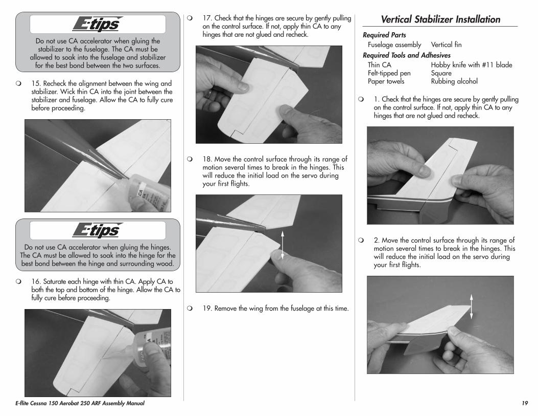
17. Check that the hinges are secure by gently pulling on the control surface. If not, apply thin CA to any hinges that are not glued and recheck.
18. Move the control surface through its range of motion several times to break in the hinges. This will reduce the initial load on the servo during your first flights.
19. Remove the wing from the fuselage at this time.
Vertical Stabilizer InstallationRequired parts
Fuselage assembly Vertical finRequired Tools and Adhesives
Thin CA Hobby knife with #11 bladeFelt-tipped pen SquarePaper towels Rubbing alcohol
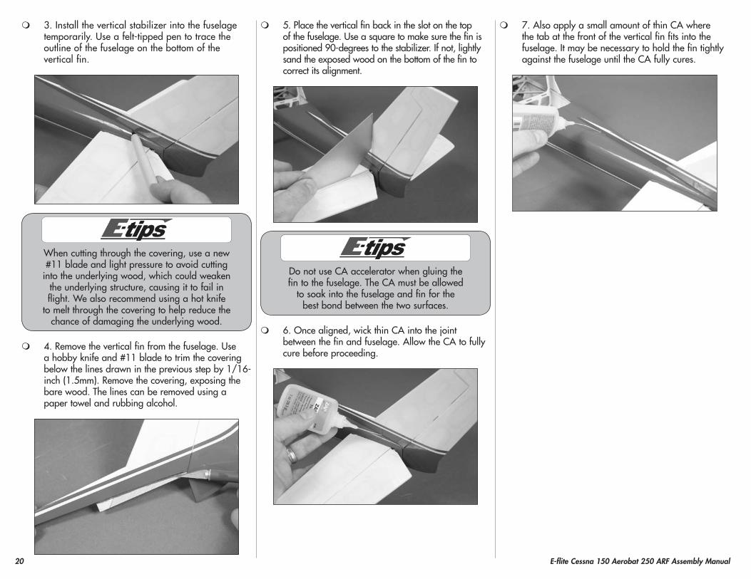
1. Check that the hinges are secure by gently pulling on the control surface. If not, apply thin CA to any hinges that are not glued and recheck.
2. Move the control surface through its range of motion several times to break in the hinges. This will reduce the initial load on the servo during your first flights.
20 E-flite Cessna 150 Aerobat 250 ARF Assembly Manual
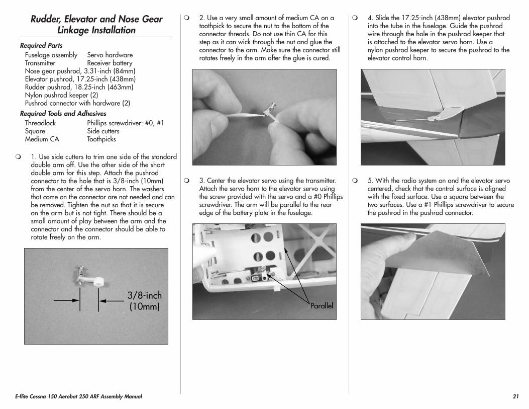
3. Install the vertical stabilizer into the fuselage temporarily. Use a felt-tipped pen to trace the outline of the fuselage on the bottom of the vertical fin.
When cutting through the covering, use a new #11 blade and light pressure to avoid cutting
into the underlying wood, which could weaken the underlying structure, causing it to fail in flight. We also recommend using a hot knife
to melt through the covering to help reduce the chance of damaging the underlying wood.
4. Remove the vertical fin from the fuselage. Use a hobby knife and #11 blade to trim the covering below the lines drawn in the previous step by 1/16-inch (1.5mm). Remove the covering, exposing the bare wood. The lines can be removed using a paper towel and rubbing alcohol.
5. Place the vertical fin back in the slot on the top of the fuselage. Use a square to make sure the fin is positioned 90-degrees to the stabilizer. If not, lightly sand the exposed wood on the bottom of the fin to correct its alignment.
Do not use CA accelerator when gluing the fin to the fuselage. The CA must be allowed
to soak into the fuselage and fin for the best bond between the two surfaces.
6. Once aligned, wick thin CA into the joint between the fin and fuselage. Allow the CA to fully cure before proceeding.
7. Also apply a small amount of thin CA where the tab at the front of the vertical fin fits into the fuselage. It may be necessary to hold the fin tightly against the fuselage until the CA fully cures.
21E-flite Cessna 150 Aerobat 250 ARF Assembly Manual
Rudder, Elevator and Nose Gear Linkage Installation
Required partsFuselage assembly Servo hardwareTransmitter Receiver batteryNose gear pushrod, 3.31-inch (84mm)Elevator pushrod, 17.25-inch (438mm)Rudder pushrod, 18.25-inch (463mm)Nylon pushrod keeper (2)Pushrod connector with hardware (2)
Required Tools and AdhesivesThreadlock Phillips screwdriver: #0, #1Square Side cuttersMedium CA Toothpicks
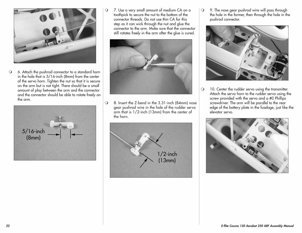
1. Use side cutters to trim one side of the standard double arm off. Use the other side of the short double arm for this step. Attach the pushrod connector to the hole that is 3/8-inch (10mm) from the center of the servo horn. The washers that come on the connector are not needed and can be removed. Tighten the nut so that it is secure on the arm but is not tight. There should be a small amount of play between the arm and the connector and the connector should be able to rotate freely on the arm.
2. Use a very small amount of medium CA on a toothpick to secure the nut to the bottom of the connector threads. Do not use thin CA for this step as it can wick through the nut and glue the connector to the arm. Make sure the connector still rotates freely in the arm after the glue is cured.
3. Center the elevator servo using the transmitter. Attach the servo horn to the elevator servo using the screw provided with the servo and a #0 Phillips screwdriver. The arm will be parallel to the rear edge of the battery plate in the fuselage.
4. Slide the 17.25-inch (438mm) elevator pushrod into the tube in the fuselage. Guide the pushrod wire through the hole in the pushrod keeper that is attached to the elevator servo horn. Use a nylon pushrod keeper to secure the pushrod to the elevator control horn.
5. With the radio system on and the elevator servo centered, check that the control surface is aligned with the fixed surface. Use a square between the two surfaces. Use a #1 Phillips screwdriver to secure the pushrod in the pushrod connector.
22 E-flite Cessna 150 Aerobat 250 ARF Assembly Manual
6. Attach the pushrod connector to a standard horn in the hole that is 5/16-inch (8mm) from the center of the servo horn. Tighten the nut so that it is secure on the arm but is not tight. There should be a small amount of play between the arm and the connector and the connector should be able to rotate freely on the arm.
7. Use a very small amount of medium CA on a toothpick to secure the nut to the bottom of the connector threads. Do not use thin CA for this step as it can wick through the nut and glue the connector to the arm. Make sure that the connector still rotates freely in the arm after the glue is cured.
8. Insert the Z-bend in the 3.31-inch (84mm) nose gear pushrod wire in the hole of the rudder servo arm that is 1/2-inch (13mm) from the center of the horn.
9. The nose gear pushrod wire will pass through the hole in the former, then through the hole in the pushrod connector.
10. Center the rudder servo using the transmitter. Attach the servo horn to the rudder servo using the screw provided with the servo and a #0 Phillips screwdriver. The arm will be parallel to the rear edge of the battery plate in the fuselage, just like the elevator servo.
23E-flite Cessna 150 Aerobat 250 ARF Assembly Manual
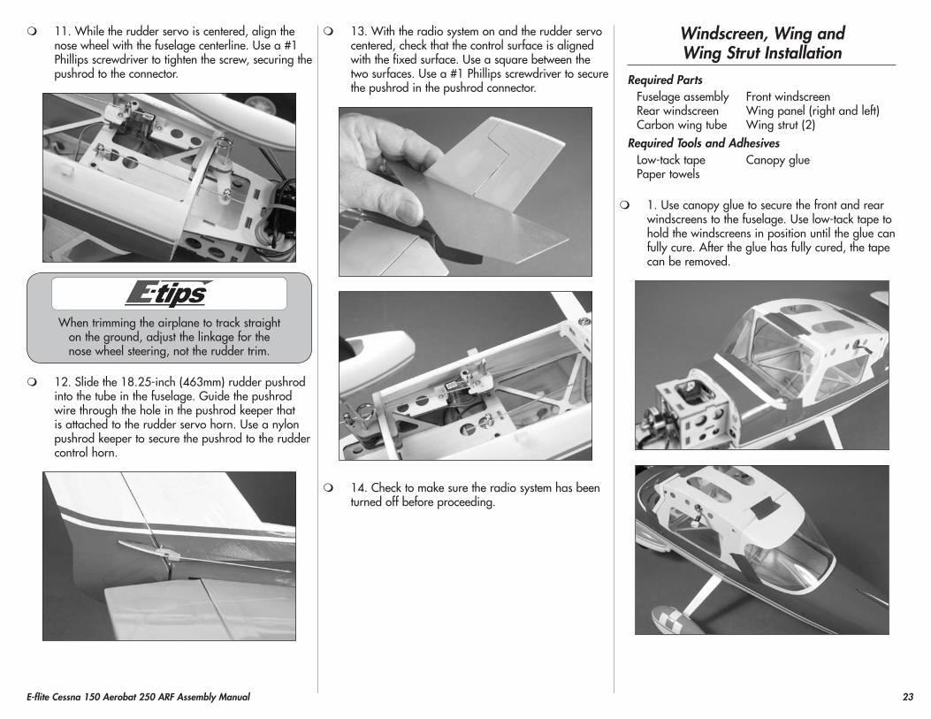
11. While the rudder servo is centered, align the nose wheel with the fuselage centerline. Use a #1 Phillips screwdriver to tighten the screw, securing the pushrod to the connector.
When trimming the airplane to track straight on the ground, adjust the linkage for the nose wheel steering, not the rudder trim.
12. Slide the 18.25-inch (463mm) rudder pushrod into the tube in the fuselage. Guide the pushrod wire through the hole in the pushrod keeper that is attached to the rudder servo horn. Use a nylon pushrod keeper to secure the pushrod to the rudder control horn.
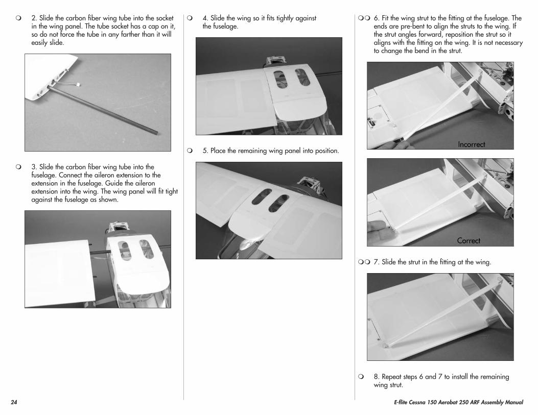
13. With the radio system on and the rudder servo centered, check that the control surface is aligned with the fixed surface. Use a square between the two surfaces. Use a #1 Phillips screwdriver to secure the pushrod in the pushrod connector.
14. Check to make sure the radio system has been turned off before proceeding.
Windscreen, Wing and Wing Strut Installation
Required partsFuselage assembly Front windscreenRear windscreen Wing panel (right and left)Carbon wing tube Wing strut (2)
Required Tools and AdhesivesLow-tack tape Canopy gluePaper towels
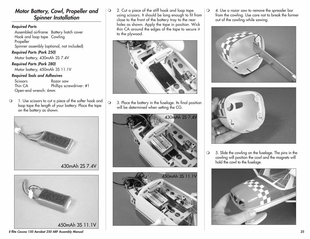
1. Use canopy glue to secure the front and rear windscreens to the fuselage. Use low-tack tape to hold the windscreens in position until the glue can fully cure. After the glue has fully cured, the tape can be removed.
24 E-flite Cessna 150 Aerobat 250 ARF Assembly Manual
2. Slide the carbon fiber wing tube into the socket in the wing panel. The tube socket has a cap on it, so do not force the tube in any farther than it will easily slide.
3. Slide the carbon fiber wing tube into the fuselage. Connect the aileron extension to the extension in the fuselage. Guide the aileron extension into the wing. The wing panel will fit tight against the fuselage as shown.
4. Slide the wing so it fits tightly against the fuselage.
5. Place the remaining wing panel into position.
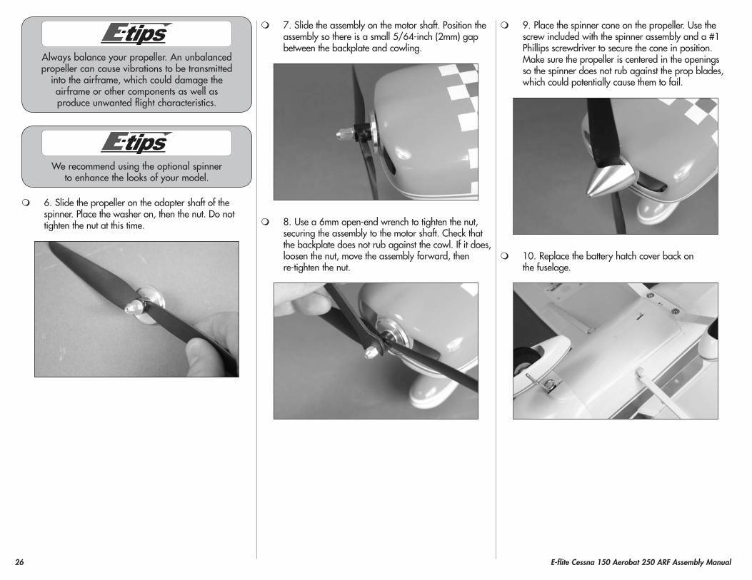
6. Fit the wing strut to the fitting at the fuselage. The ends are pre-bent to align the struts to the wing. If the strut angles forward, reposition the strut so it aligns with the fitting on the wing. It is not necessary to change the bend in the strut.
7. Slide the strut in the fitting at the wing.
8. Repeat steps 6 and 7 to install the remaining wing strut.
25E-flite Cessna 150 Aerobat 250 ARF Assembly Manual
Motor Battery, Cowl, propeller and Spinner Installation
Required partsAssembled airframe Battery hatch coverHook and loop tape CowlingPropellerSpinner assembly (optional, not included)
Required parts (park 250)Motor battery, 430mAh 2S 7.4V
Required parts (park 280)Motor battery, 450mAh 3S 11.1V
Required Tools and AdhesivesScissors Razor sawThin CA Phillips screwdriver: #1Open-end wrench: 6mm
1. Use scissors to cut a piece of the softer hook and loop tape the length of your battery. Place the tape on the battery as shown.
2. Cut a piece of the stiff hook and loop tape using scissors. It should be long enough to fit from close to the front of the battery tray to the rear holes as shown. Apply the tape in position. Wick thin CA around the edges of the tape to secure it to the plywood.
3. Place the battery in the fuselage. Its final position will be determined when setting the CG.
4. Use a razor saw to remove the spreader bar from the cowling. Use care not to break the former out of the cowling while sawing.
5. Slide the cowling on the fuselage. The pins in the cowling will position the cowl and the magnets will hold the cowl to the fuselage.
26 E-flite Cessna 150 Aerobat 250 ARF Assembly Manual
Always balance your propeller. An unbalanced propeller can cause vibrations to be transmitted
into the airframe, which could damage the airframe or other components as well as produce unwanted flight characteristics.
We recommend using the optional spinner to enhance the looks of your model.
6. Slide the propeller on the adapter shaft of the spinner. Place the washer on, then the nut. Do not tighten the nut at this time.
7. Slide the assembly on the motor shaft. Position the assembly so there is a small 5/64-inch (2mm) gap between the backplate and cowling.
8. Use a 6mm open-end wrench to tighten the nut, securing the assembly to the motor shaft. Check that the backplate does not rub against the cowl. If it does, loosen the nut, move the assembly forward, then re-tighten the nut.
9. Place the spinner cone on the propeller. Use the screw included with the spinner assembly and a #1 Phillips screwdriver to secure the cone in position. Make sure the propeller is centered in the openings so the spinner does not rub against the prop blades, which could potentially cause them to fail.
10. Replace the battery hatch cover back on the fuselage.
27E-flite Cessna 150 Aerobat 250 ARF Assembly Manual
Decal InstallationRequired parts
Fuselage assembly Wing assemblyRequired Tools and Adhesives
Spray bottle Dish washing detergentPaper towel Hobby knife with #11 blade
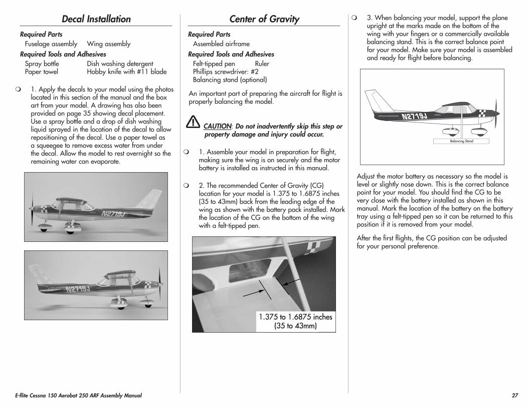
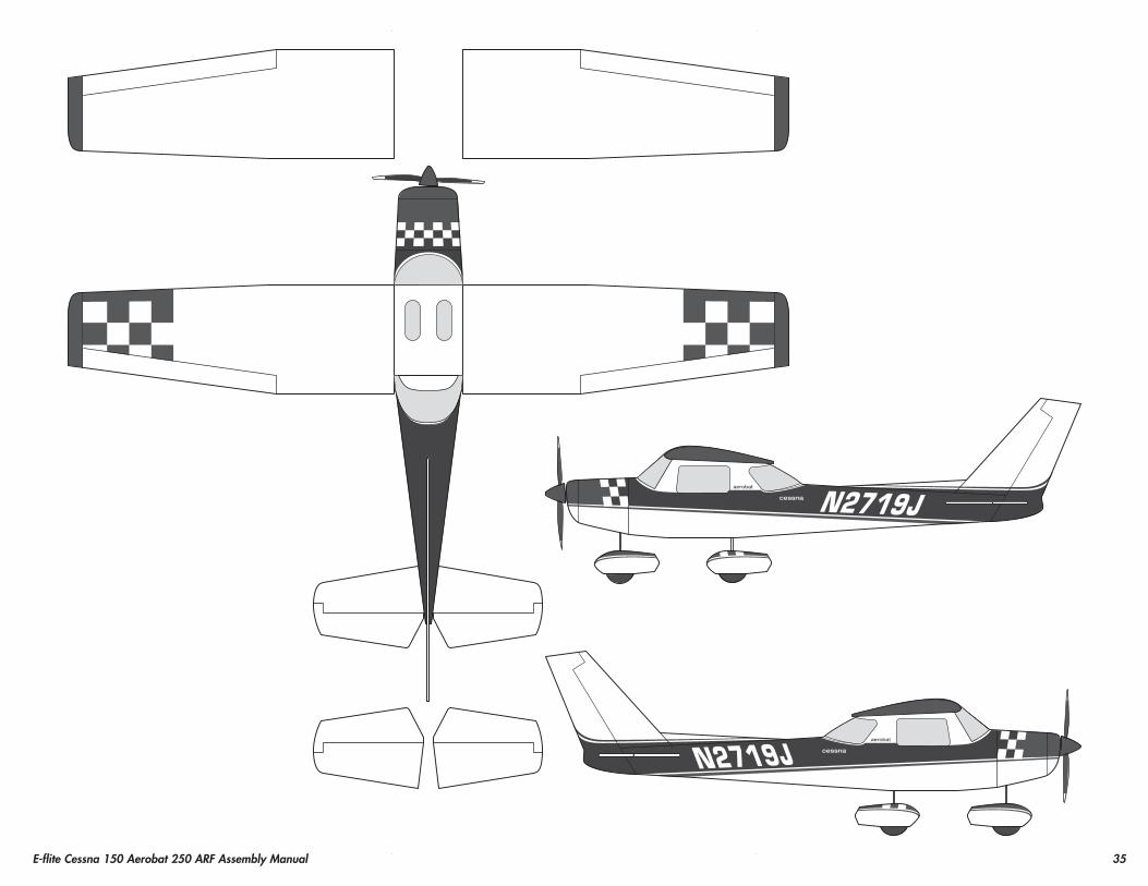
1. Apply the decals to your model using the photos located in this section of the manual and the box art from your model. A drawing has also been provided on page 35 showing decal placement. Use a spray bottle and a drop of dish washing liquid sprayed in the location of the decal to allow repositioning of the decal. Use a paper towel as a squeegee to remove excess water from under the decal. Allow the model to rest overnight so the remaining water can evaporate.
Center of GravityRequired parts
Assembled airframeRequired Tools and Adhesives
Felt-tipped pen RulerPhillips screwdriver: #2Balancing stand (optional)
An important part of preparing the aircraft for flight is properly balancing the model.
CAUTION: Do not inadvertently skip this step or property damage and injury could occur.
1. Assemble your model in preparation for flight, making sure the wing is on securely and the motor battery is installed as instructed in this manual.
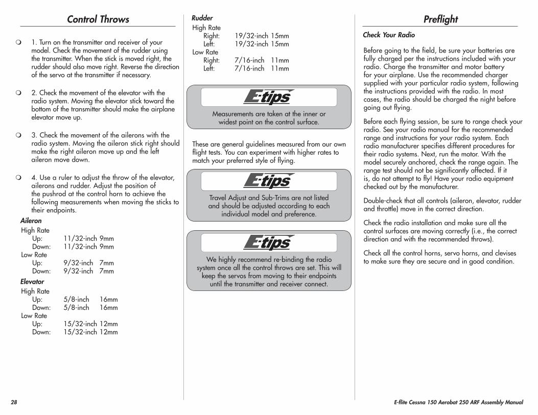
2. The recommended Center of Gravity (CG) location for your model is 1.375 to 1.6875 inches (35 to 43mm) back from the leading edge of the wing as shown with the battery pack installed. Mark the location of the CG on the bottom of the wing with a felt-tipped pen.
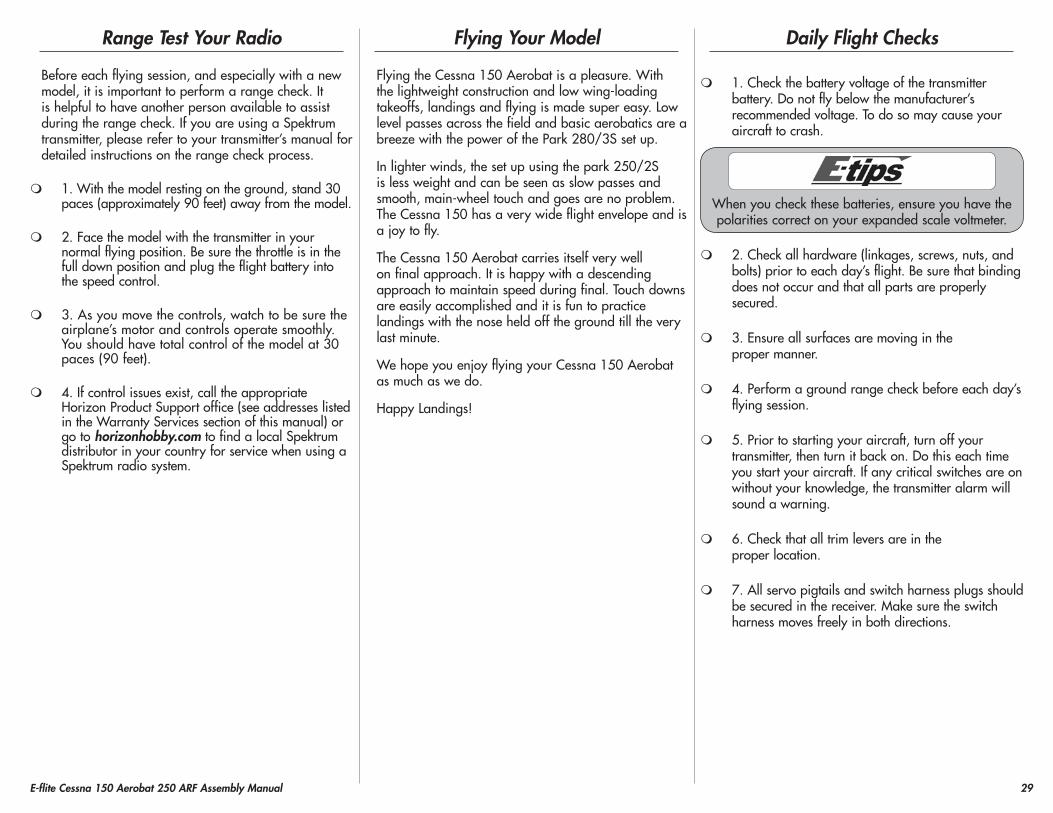
3. When balancing your model, support the plane upright at the marks made on the bottom of the wing with your fingers or a commercially available balancing stand. This is the correct balance point for your model. Make sure your model is assembled and ready for flight before balancing.
Balancing Stand
Adjust the motor battery as necessary so the model is level or slightly nose down. This is the correct balance point for your model. You should find the CG to be very close with the battery installed as shown in this manual. Mark the location of the battery on the battery tray using a felt-tipped pen so it can be returned to this position if it is removed from your model.
After the first flights, the CG position can be adjusted for your personal preference.
28 E-flite Cessna 150 Aerobat 250 ARF Assembly Manual
Control Throws
1. Turn on the transmitter and receiver of your model. Check the movement of the rudder using the transmitter. When the stick is moved right, the rudder should also move right. Reverse the direction of the servo at the transmitter if necessary.
2. Check the movement of the elevator with the radio system. Moving the elevator stick toward the bottom of the transmitter should make the airplane elevator move up.
3. Check the movement of the ailerons with the radio system. Moving the aileron stick right should make the right aileron move up and the left aileron move down.
4. Use a ruler to adjust the throw of the elevator, ailerons and rudder. Adjust the position of the pushrod at the control horn to achieve the following measurements when moving the sticks to their endpoints.
AileronHigh Rate Up: 11/32-inch 9mm Down: 11/32-inch 9mmLow Rate Up: 9/32-inch 7mm Down: 9/32-inch 7mmElevatorHigh Rate Up: 5/8-inch 16mm Down: 5/8-inch 16mmLow Rate Up: 15/32-inch 12mm Down: 15/32-inch 12mm
RudderHigh Rate Right: 19/32-inch 15mm Left: 19/32-inch 15mmLow Rate Right: 7/16-inch 11mm Left: 7/16-inch 11mm
Measurements are taken at the inner or widest point on the control surface.
These are general guidelines measured from our own flight tests. You can experiment with higher rates to match your preferred style of flying.
Travel Adjust and Sub-Trims are not listed and should be adjusted according to each
individual model and preference.
We highly recommend re-binding the radio system once all the control throws are set. This will
keep the servos from moving to their endpoints until the transmitter and receiver connect.
preflightCheck your Radio
Before going to the field, be sure your batteries are fully charged per the instructions included with your radio. Charge the transmitter and motor battery for your airplane. Use the recommended charger supplied with your particular radio system, following the instructions provided with the radio. In most cases, the radio should be charged the night before going out flying.
Before each flying session, be sure to range check your radio. See your radio manual for the recommended range and instructions for your radio system. Each radio manufacturer specifies different procedures for their radio systems. Next, run the motor. With the model securely anchored, check the range again. The range test should not be significantly affected. If it is, do not attempt to fly! Have your radio equipment checked out by the manufacturer.
Double-check that all controls (aileron, elevator, rudder and throttle) move in the correct direction.
Check the radio installation and make sure all the control surfaces are moving correctly (i.e., the correct direction and with the recommended throws).
Check all the control horns, servo horns, and clevises to make sure they are secure and in good condition.
29E-flite Cessna 150 Aerobat 250 ARF Assembly Manual
Range Test your Radio
Before each flying session, and especially with a new model, it is important to perform a range check. It is helpful to have another person available to assist during the range check. If you are using a Spektrum transmitter, please refer to your transmitter’s manual for detailed instructions on the range check process.
1. With the model resting on the ground, stand 30 paces (approximately 90 feet) away from the model.
2. Face the model with the transmitter in your normal flying position. Be sure the throttle is in the full down position and plug the flight battery into the speed control.
3. As you move the controls, watch to be sure the airplane’s motor and controls operate smoothly. You should have total control of the model at 30 paces (90 feet).
4. If control issues exist, call the appropriate Horizon Product Support office (see addresses listed in the Warranty Services section of this manual) or go to horizonhobby.com to find a local Spektrum distributor in your country for service when using a Spektrum radio system.
Flying your Model
Flying the Cessna 150 Aerobat is a pleasure. With the lightweight construction and low wing-loading takeoffs, landings and flying is made super easy. Low level passes across the field and basic aerobatics are a breeze with the power of the Park 280/3S set up.
In lighter winds, the set up using the park 250/2S is less weight and can be seen as slow passes and smooth, main-wheel touch and goes are no problem. The Cessna 150 has a very wide flight envelope and is a joy to fly.
The Cessna 150 Aerobat carries itself very well on final approach. It is happy with a descending approach to maintain speed during final. Touch downs are easily accomplished and it is fun to practice landings with the nose held off the ground till the very last minute.
We hope you enjoy flying your Cessna 150 Aerobat as much as we do.
Happy Landings!
Daily Flight Checks
1. Check the battery voltage of the transmitter battery. Do not fly below the manufacturer’s recommended voltage. To do so may cause your aircraft to crash.
When you check these batteries, ensure you have the polarities correct on your expanded scale voltmeter.
2. Check all hardware (linkages, screws, nuts, and bolts) prior to each day’s flight. Be sure that binding does not occur and that all parts are properly secured.
3. Ensure all surfaces are moving in the proper manner.
4. Perform a ground range check before each day’s flying session.
5. Prior to starting your aircraft, turn off your transmitter, then turn it back on. Do this each time you start your aircraft. If any critical switches are on without your knowledge, the transmitter alarm will sound a warning.
6. Check that all trim levers are in the proper location.
7. All servo pigtails and switch harness plugs should be secured in the receiver. Make sure the switch harness moves freely in both directions.
30 E-flite Cessna 150 Aerobat 250 ARF Assembly Manual
Limited Warranty
WhAT ThIS WARRANTy COVERS
Horizon Hobby, Inc. (“Horizon”) warrants to the original purchaser that the product purchased (the “Product”) will be free from defects in materials and workmanship at the date of purchase.
WhAT IS NOT COVERED
This warranty is not transferable and does not cover (i) cosmetic damage, (ii) damage due to acts of God, accident, misuse, abuse, negligence, commercial use, or due to improper use, installation, operation or maintenance, (iii) modification of or to any part of the Product, (iv) attempted service by anyone other than a Horizon Hobby authorized service center, or (v) Products not purchased from an authorized Horizon dealer.
OTHER THAN THE EXPRESS WARRANTY ABOVE, HORIZON MAKES NO OTHER WARRANTY OR REPRESENTATION, AND HEREBY DISCLAIMS ANY AND ALL IMPLIED WARRANTIES, INCLUDING, WITHOUT LIMITATION, THE IMPLIED WARRANTIES OF NON-INFRINGEMENT, MERCHANTABILITY AND FITNESS FOR A PARTICULAR PURPOSE. THE PURCHASER ACKNOWLEDGES THAT THEY ALONE HAVE DETERMINED THAT THE PRODUCT WILL SUITABLY MEET THE REQUIREMENTS OF THE PURCHASER’S INTENDED USE.
pURChASER’S REMEDy
Horizon’s sole obligation and purchaser’s sole and exclusive remedy shall be that Horizon will, at its option, either (i) service, or (ii) replace, any Product determined by Horizon to be defective. Horizon reserves the right to inspect any and all Product(s) involved in a warranty claim. Service or replacement decisions are at the sole discretion of Horizon. Proof of purchase is required for all warranty claims. SERVICE OR REPLACEMENT AS PROVIDED UNDER THIS WARRANTY IS THE PURCHASER’S SOLE AND EXCLUSIVE REMEDY.
LIMITATION OF LIABILITy
HORIZON SHALL NOT BE LIABLE FOR SPECIAL, INDIRECT, INCIDENTAL OR CONSEQUENTIAL DAMAGES, LOSS OF PROFITS OR PRODUCTION OR COMMERCIAL LOSS IN ANY WAY, REGARDLESS OF WHETHER SUCH CLAIM IS BASED IN CONTRACT, WARRANTY, TORT, NEGLIGENCE, STRICT LIABILITY OR ANY OTHER THEORY OF LIABILITY, EVEN IF HORIZON HAS BEEN ADVISED OF THE POSSIBILITY OF SUCH DAMAGES. Further, in no event shall the liability of Horizon exceed the individual price of the Product on which liability is asserted. As Horizon has no control over use, setup, final assembly, modification or misuse, no liability shall be assumed nor accepted for any resulting damage or injury. By the act of use, setup or assembly, the user accepts all resulting liability. If you as the purchaser or user are not prepared to accept the liability associated with the use of the Product, purchaser is advised to return the Product immediately in new and unused condition to the place of purchase.
LAW
These terms are governed by Illinois law (without regard to conflict of law principals). This warranty gives you specific legal rights, and you may also have other rights which vary from state to state. Horizon reserves the right to change or modify this warranty at any time without notice.
Warranty Services
QUESTIONS, ASSISTANCE, AND SERVICES
Your local hobby store and/or place of purchase cannot provide warranty support or service. Once assembly, setup or use of the Product has been started, you must contact Horizon directly. This will enable Horizon to better answer your questions and service you in the event that you may need any assistance. For questions or assistance, please direct your email to [email protected], or call 877.504.0233 toll free to speak to a Product Support representative. You may also find information on our website at www.horizonhobby.com.
INSpECTION OR SERVICES
If this Product needs to be inspected or serviced, please use the Horizon Online Service Request submission process found on our website or call Horizon to obtain a Return Merchandise Authorization (RMA) number. Pack the Product securely using a shipping carton. Please note that original boxes may be included, but are not designed to withstand the rigors of shipping without additional protection. Ship via a carrier that provides tracking and insurance for lost or damaged parcels, as Horizon is not responsible for merchandise until it arrives and is accepted at our facility. An Online Service Request is available at http://www.horizonhobby.com under the Support tab. If you do not have internet access, please contact Horizon Product Support to obtain a RMA number along with instructions for submitting your product for service. When calling Horizon, you will be asked to provide your complete name, street address, email address and phone number where you can be reached during business hours. When sending product into Horizon, please include your RMA number, a list of the included items, and a brief summary of the problem. A copy of your original sales receipt must be included for warranty consideration. Be sure your name, address, and RMA number are clearly written on the outside of the shipping carton.Notice: Do not ship Lipo batteries to horizon. If you have any issue with a Lipo battery, please contact the appropriate horizon product Support office.
31E-flite Cessna 150 Aerobat 250 ARF Assembly Manual
WARRANTy REQUIREMENTS
For Warranty consideration, you must include your original sales receipt verifying the proof-of-purchase date. Provided warranty conditions have been met, your Product will be serviced or replaced free of charge. Service or replacement decisions are at the sole discretion of Horizon.
NON-WARRANTy SERVICE
Should your service not be covered by warranty service will be completed and payment will be required without notification or estimate of the expense unless the expense exceeds 50% of the retail purchase cost. By submitting the item for service you are agreeing to payment of the service without notification. Service estimates are available upon request. You must include this request with your item submitted for service. Non-warranty service estimates will be billed a minimum of ½ hour of labor. In addition you will be billed for return freight. Horizon accepts money orders and cashiers checks, as well as Visa, MasterCard, American Express, and Discover cards. By submitting any item to Horizon for service, you are agreeing to Horizon’s Terms and Conditions found on our website http://www.horizonhobby.com/Service/Request/.
UNITED STATES(Electronics and engines)Horizon Service Center
4105 Fieldstone RdChampaign, Illinois
61822 [email protected]
877-504-0233Online Repair Request visit:
www.horizonhobby.com/service
(All other products)Horizon Product Support
4105 Fieldstone RdChampaign, Illinois
61822 [email protected]
877-504-0233
UNITED KINGDOMHorizon Hobby LimitedUnits 1-4 Ployters Rd
Staple TyeHarlow, EssexCM18 7NS
United [email protected]+44 (0) 1279 641 097
GERMANyHorizon Technischer Service
Hamburger Str. 1025335 Elmshorn
+49 4121 46199 66
FRANCEHorizon Hobby SAS14 Rue Gustave Eiffel
Zone d’Activité du Réveil Matin91230 Montgeron
+33 (0) 1 60 47 44 70
Compliance Information for the European Union
InstructIons for DIsposal of WEEE by usErs In thE EuropEan unIon
This product must not be disposed of with other waste. Instead, it is the user’s responsibility to dispose of their waste equipment by handing it over to a designated collection point for the recycling of waste electrical and electronic equipment. The separate collection and recycling of your waste equipment at the time of disposal will help to conserve natural resources and ensure that it is recycled in a manner that protects human health and the environment. For more information about where you can drop off your waste equipment for recycling, please contact your local city office, your household waste disposal service or where you purchased the product.
32 E-flite Cessna 150 Aerobat 250 ARF Assembly Manual
Academy of Model Aeronautics National Model Aircraft Safety Code
Effective January 1, 2011A. GENERAL
A model aircraft is a non-human-carrying aircraft capable of sustained flight in the atmosphere. It may not exceed limitations of this code and is intended exclusively for sport, recreation and/or competition. All model flights must be conducted in accordance with this safety code and any additional rules specific to the flying site.
1. Model aircraft will not be flown:(a) In a careless or reckless manner.(b) At a location where model aircraft activities are prohibited.
2. Model aircraft pilots will:(a) Yield the right of way to all man carrying aircraft.b) See and avoid all aircraft and a spotter must be used when appropriate. (AMA Document #540-D-See and Avoid Guidance.)(c) Not fly higher than approximately 400 feet above ground level within three (3) miles of an airport, without notifying the airport operator.(d) Not interfere with operations and traffic patterns at any airport, heliport or seaplane base except where there is a mixed use agreement.(e) Not exceed a takeoff weight, including fuel, of 55 pounds unless in compliance with the AMA Large Model Aircraft program. (AMA Document 520-A)(f) Ensure the aircraft is identified with the name and address or AMA number of the owner on the inside or affixed to the outside of the model aircraft. (This does not apply to model aircraft flown indoors).(g) Not operate aircraft with metal-blade propellers or with gaseous boosts except for helicopters operated under the provisions of AMA Document #555.(h) Not operate model aircraft while under the influence of alcohol or while using any drug which could adversely affect the pilot’s ability to safely control the model.
(i) Not operate model aircraft carrying pyrotechnic devices which explode or burn, or any device which propels a projectile or drops any object that creates a hazard to persons or property.
Exceptions:
•FreeFlightfusesordevicesthatburnproducingsmokeand are securely attached to the model aircraft during flight.
•Rocketmotors(usingsolidpropellant)uptoaG-seriessize may be used provided they remain attached to the model during flight. Model rockets may be flown in accordance with the National Model Rocketry Safety Code but may not be launched from model aircraft.
•OfficiallydesignatedAMAAirShowTeams(AST)areauthorized to use devices and practices as defined within the Team AMA Program Document (AMA Document #718).(j) Not operate a turbine-powered aircraft, unless in compliance with the AMA turbine regulations. (AMA Document #510-A).
3. Model aircraft will not be flown in AMA sanctioned events, air shows or model demonstrations unless:(a) The aircraft, control system and pilot skills have successfully demonstrated all maneuvers intended or anticipated prior to the specific event.(b) An inexperienced pilot is assisted by an experienced pilot.
4. When and where required by rule, helmets must be properly worn and fastened. They must be OSHA, DOT, ANSI, SNELL or NOCSAE approved or comply with comparable standards.
B. RADIO CONTROL (RC)
1. All pilots shall avoid flying directly over unprotected people, vessels, vehicles or structures and shall avoid endangerment of life and property of others.
2. A successful radio equipment ground-range check in accordance with manufacturer’s recommendations will be completed before the first flight of a new or repaired model aircraft.
3. At all flying sites a safety line(s) must be established in front of which all flying takes place (AMA Document #706-Recommended Field Layout):(a) Only personnel associated with flying the model aircraft are allowed at or in front of the safety line.(b) At air shows or demonstrations, a straight safety line must be established.(c) An area away from the safety line must be maintained for spectators.(d) Intentional flying behind the safety line is prohibited.
4. RC model aircraft must use the radio-control frequencies currently allowed by the Federal Communications Commission (FCC). Only individuals properly licensed by the FCC are authorized to operate equipment on Amateur Band frequencies.
5. RC model aircraft will not operate within three (3) miles of any pre-existing flying site without a frequency-management agreement (AMA Documents #922- Testing for RF Interference; #923- Frequency Management Agreement)
6. With the exception of events flown under official AMA Competition Regulations, excluding takeoff and landing, no powered model may be flown outdoors closer than 25 feet to any individual, except for the pilot and the pilot’s helper(s) located at the flight line.
7. Under no circumstances may a pilot or other person touch a model aircraft in flight while it is still under power, except to divert it from striking an individual. This does not apply to model aircraft flown indoors.
8. RC night flying requires a lighting system providing the pilot with a clear view of the model’s attitude and orientation at all times.
9. The pilot of a RC model aircraft shall:(a) Maintain control during the entire flight, maintaining visual contact without enhancement other than by corrective lenses prescribed for the pilot.(b) Fly using the assistance of a camera or First-Person View (FPV) only in accordance with the procedures outlined in AMA Document #550.
33E-flite Cessna 150 Aerobat 250 ARF Assembly Manual
C. FREE FLIGhT
1. Must be at least 100 feet downwind of spectators and automobile parking when the model aircraft is launched.
2. Launch area must be clear of all individuals except mechanics, officials, and other fliers.
3. An effective device will be used to extinguish any fuse on the model aircraft after the fuse has completed its function.
D. CONTROL LINE
1. The complete control system (including the safety thong where applicable) must have an inspection and pull test prior to flying.
2. The pull test will be in accordance with the current Competition Regulations for the applicable model aircraft category.
3. Model aircraft not fitting a specific category shall use those pull-test requirements as indicated for Control Line Precision Aerobatics.
4. The flying area must be clear of all utility wires or poles and a model aircraft will not be flown closer than 50 feet to any above-ground electric utility lines.
5. The flying area must be clear of all nonessential participants and spectators before the engine is started.
Building and Flying Notes
34 E-flite Cessna 150 Aerobat 250 ARF Assembly Manual
Building and Flying Notes
35E-flite Cessna 150 Aerobat 250 ARF Assembly Manual
18126 Created 06/2011
TM
© 2011 Horizon Hobby, Inc.horizonhobby.com www.e-fliterc.com
E-flite, UltraCote, ParkLite, Celectra, DSM2, DSMX and the Horizon Hobby logo are trademarks or registered trademarks of Horizon Hobby, Inc. The Spektrum trademark is used with permission of Bachmann Industries, Inc.
Cessna and Cessna 150 are trademarks or registered trademarks of Textron Innovations, Inc. and are used under license by Horizon Hobby, Inc.
All other trademarks, service marks and logos are the property of their respective owners.