Embed Size (px)
Citation preview
CETECOM Inc. CETECOM Inc. 411 Dixon Landing Road, Milpitas, CA-95035, USA Phone: +1 408 586 6200 Fax: +1 408 586 6299 www.cetecom.com Issued test report consists of 33 Pages Page 1 (33)
Test report no.: EMC_381EN328_2002 ETSI EN 300 328 V1.4.1 (2002-11)
ETSI EN 300 328-2 V1.2.1 (2001-12) (BCM94306CB)
FCC LISTED, REG. NO.: 101450 &
RECOGNIZED BY INDUSTRY CANADA IC – 3925

CETECOM Inc. Test report no.:EMC_381EN328-2002 Issue date:2003-01-10 Page 2 (33)
Table of Contents 1 General information 1.1 Notes 1.2 Testing laboratory 1.3 Details of applicant 1.4 Application details 1.5 Test item 1.6 Test standards 2 Technical test 2.1 Summary of test results 2.2 Test report 1 General information 1.1 Notes The test results of this test report relate exclusively to the test item specified in 1.5. The CETECOM Inc. USA does not assume responsibility for any conclusions and generalisations drawn from the test results with regard to other specimens or samples of the type of the equipment represented by the test item. The test report may only be reproduced or published in full. Reproduction or publication of extracts from the report requires the prior written approval of the CETECOM Inc USA. TEST REPORT PREPARED BY: EMC Engineer: Harpreet Sidhu 1.2 Testing laboratory CETECOM Inc. 411 Dixon Landing Road, Milpitas, CA-95035, USA Phone: +1 408 586 6200 Fax: +1 408 586 6299 E-mail: [email protected] Internet: www.cetecom.com
CETECOM Inc. Test report no.:EMC_381EN328-2002 Issue date:2003-01-10 Page 3 (33)
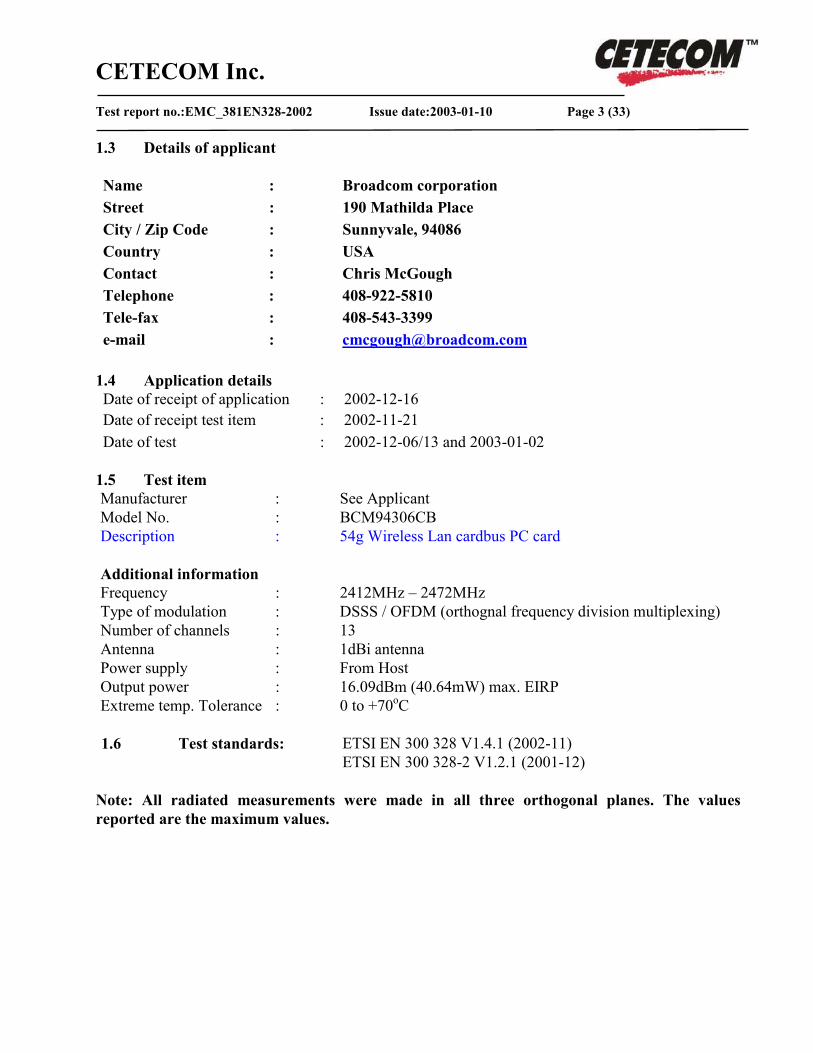
1.3 Details of applicant Name : Broadcom corporation Street : 190 Mathilda Place City / Zip Code : Sunnyvale, 94086 Country : USA Contact : Chris McGough Telephone : 408-922-5810 Tele-fax : 408-543-3399 e-mail : [email protected]
1.4 Application details Date of receipt of application : 2002-12-16 Date of receipt test item : 2002-11-21 Date of test : 2002-12-06/13 and 2003-01-02
1.5 Test item Manufacturer : See Applicant Model No. : BCM94306CB Description : 54g Wireless Lan cardbus PC card Additional information
Frequency : 2412MHz – 2472MHz Type of modulation : DSSS / OFDM (orthognal frequency division multiplexing) Number of channels : 13 Antenna : 1dBi antenna Power supply : From Host Output power : 16.09dBm (40.64mW) max. EIRP Extreme temp. Tolerance : 0 to +70oC
1.6 Test standards: ETSI EN 300 328 V1.4.1 (2002-11)
ETSI EN 300 328-2 V1.2.1 (2001-12)
Note: All radiated measurements were made in all three orthogonal planes. The values reported are the maximum values.
CETECOM Inc. Test report no.:EMC_381EN328-2002 Issue date:2003-01-10 Page 4 (33)
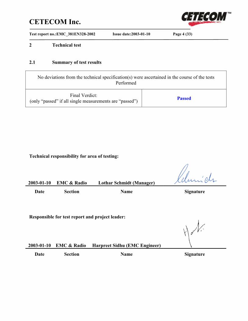
2 Technical test 2.1 Summary of test results
No deviations from the technical specification(s) were ascertained in the course of the tests Performed
Final Verdict: (only “passed” if all single measurements are “passed”) Passed
Technical responsibility for area of testing:
2003-01-10 EMC & Radio Lothar Schmidt (Manager) Date Section Name Signature
Responsible for test report and project leader:
2003-01-10 EMC & Radio Harpreet Sidhu (EMC Engineer) Date Section Name Signature

CETECOM Inc. Test report no.:EMC_381EN328-2002 Issue date:2003-01-10 Page 5 (33)
2.2 Test report
TEST REPORT
Test report no. : EMC_381EN328_2002 (BCM94306CB)
CETECOM Inc. Test report no.:EMC_381EN328-2002 Issue date:2003-01-10 Page 6 (33)
TEST REPORT REFERENCE
LIST OF MEASUREMENTS PAGE
EFFECTIVE ISOTROPIC RADIATED POWER CLAUSE 5.2.1 7
PEAK POWER DENSITY CLAUSE 5.2.2 9
FREQUENCY RANGE CLAUSE 5.2.3 13
SPURIOUS EMISSIONS CLAUSE 5.2.4 16
RECEIVER SPURIOUS EMISSIONS CLAUSE 5.3.2 24
TEST EQUIPMENT AND ANCILLARIES USED FOR TESTS 28
PHOTOGRAPHS 29
BLOCK DIAGRAMS 32
Note: The clause numbers are referenced to ETSI EN 300 328 V1.4.1 (2002-11)
CETECOM Inc. Test report no.:EMC_381EN328-2002 Issue date:2003-01-10 Page 7 (33)
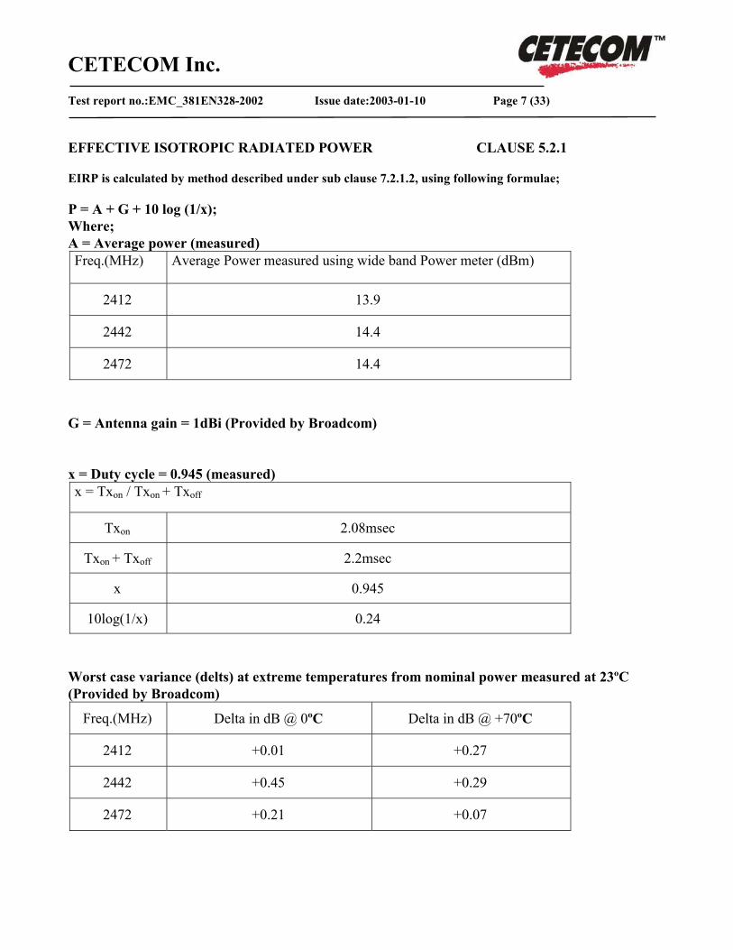
EFFECTIVE ISOTROPIC RADIATED POWER CLAUSE 5.2.1 EIRP is calculated by method described under sub clause 7.2.1.2, using following formulae; P = A + G + 10 log (1/x); Where; A = Average power (measured) Freq.(MHz) Average Power measured using wide band Power meter (dBm)
2412 13.9
2442 14.4
2472 14.4
G = Antenna gain = 1dBi (Provided by Broadcom) x = Duty cycle = 0.945 (measured) x = Txon / Txon + Txoff
Txon 2.08msec
Txon + Txoff 2.2msec
x 0.945
10log(1/x) 0.24
Worst case variance (delts) at extreme temperatures from nominal power measured at 23ºC (Provided by Broadcom)
Freq.(MHz) Delta in dB @ 0ºC Delta in dB @ +70ºC
2412 +0.01 +0.27
2442 +0.45 +0.29
2472 +0.21 +0.07

CETECOM Inc. Test report no.:EMC_381EN328-2002 Issue date:2003-01-10 Page 8 (33)
EFFECTIVE ISOTROPIC RADIATED POWER CLAUSE 5.2.1
TRANSMITTER POWER (dBm) EIRP
TEST CONDITIONS
Low frequency
2412MHz
Mid frequency
2442MHz
High frequency
2472MHz
Tnom( 23 )0C Vnom (3.3) Pk 15.14 Pk 15.64 Pk 15.64
Tmin( 0 )0C Vnom(3.3) Pk 15.15 Pk 16.09 Pk 15.85
Tmax( +70 )0C Vnom(3.3) Pk 15.41 Pk 15.93 Pk 15.71
Av – Average power during Burst
LIMITS: CLAUSE 5.2.1
Under all test conditions ≤ 20dBm / -10dBW / 100mW
CETECOM Inc. Test report no.:EMC_381EN328-2002 Issue date:2003-01-10 Page 9 (33)
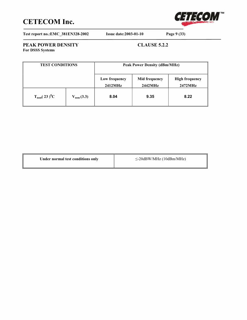
PEAK POWER DENSITY CLAUSE 5.2.2 For DSSS Systems
Peak Power Density (dBm/MHz)
TEST CONDITIONS
Low frequency
2412MHz
Mid frequency
2442MHz
High frequency
2472MHz
Tnom( 23 )0C Vnom (3.3) 8.04 9.35 8.22
Under normal test conditions only
≤-20dBW/MHz (10dBm/MHz)

CETECOM Inc. Test report no.:EMC_381EN328-2002 Issue date:2003-01-10 Page 10 (33)
PEAK POWER DENSITY CLAUSE 5.2.2 Lowest Channel: 2412MHz Notes: -51.96 dBm/Hz is added with 60dB to compensate for the dBm/MHz, therefore 8.04dBm/MHz.
CETECOM Inc. Test report no.:EMC_381EN328-2002 Issue date:2003-01-10 Page 11 (33)
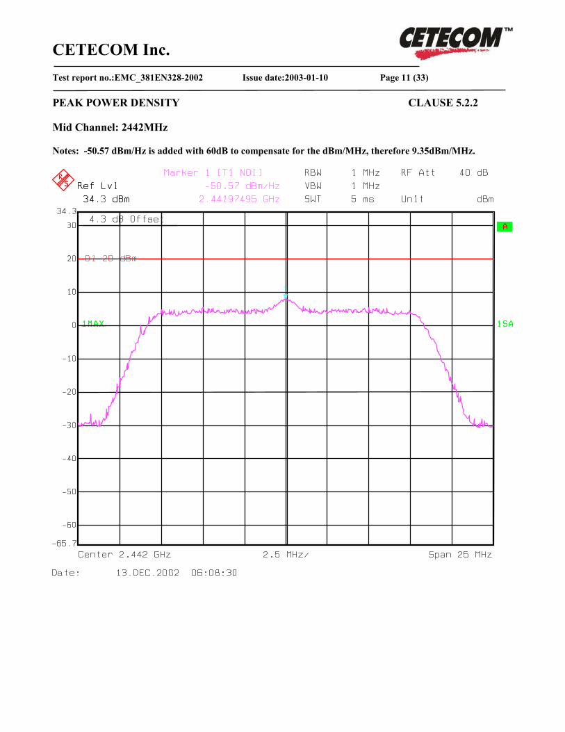
PEAK POWER DENSITY CLAUSE 5.2.2 Mid Channel: 2442MHz Notes: -50.57 dBm/Hz is added with 60dB to compensate for the dBm/MHz, therefore 9.35dBm/MHz.

CETECOM Inc. Test report no.:EMC_381EN328-2002 Issue date:2003-01-10 Page 12 (33)
PEAK POWER DENSITY CLAUSE 5.2.2 Highest Channel: 2472MHz Notes: -51.78 dBm/Hz is added with 60dB to compensate for the dBm/MHz, therefore 8.22dBm/MHz.
CETECOM Inc. Test report no.:EMC_381EN328-2002 Issue date:2003-01-10 Page 13 (33)
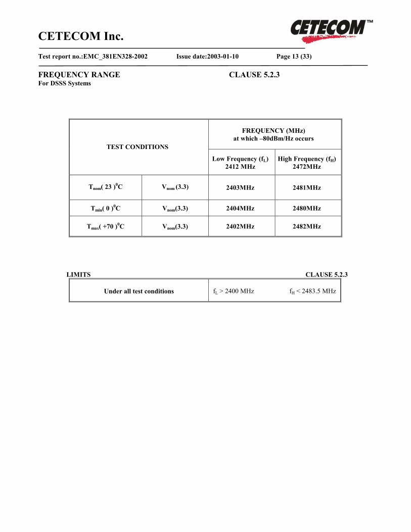
FREQUENCY RANGE CLAUSE 5.2.3 For DSSS Systems
FREQUENCY (MHz) at which –80dBm/Hz occurs
TEST CONDITIONS
Low Frequency (fL) 2412 MHz
High Frequency (fH) 2472MHz
Tnom( 23 )0C Vnom (3.3) 2403MHz 2481MHz
Tmin( 0 )0C Vnom(3.3) 2404MHz 2480MHz
Tmax( +70 )0C Vnom(3.3) 2402MHz 2482MHz
LIMITS CLAUSE 5.2.3
Under all test conditions fL > 2400 MHz fH < 2483.5 MHz
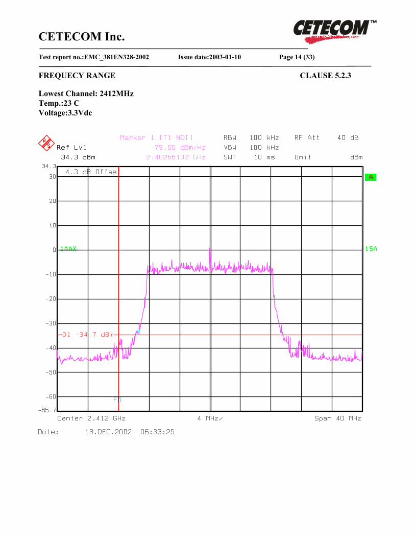
CETECOM Inc. Test report no.:EMC_381EN328-2002 Issue date:2003-01-10 Page 14 (33)
FREQUECY RANGE CLAUSE 5.2.3 Lowest Channel: 2412MHz Temp.:23 C Voltage:3.3Vdc
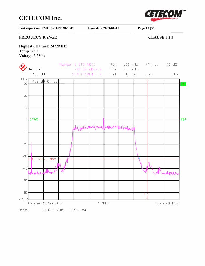
CETECOM Inc. Test report no.:EMC_381EN328-2002 Issue date:2003-01-10 Page 15 (33)
FREQUECY RANGE CLAUSE 5.2.3 Highest Channel: 2472MHz Temp.:23 C Voltage:3.3Vdc
CETECOM Inc. Test report no.:EMC_381EN328-2002 Issue date:2003-01-10 Page 16 (33)
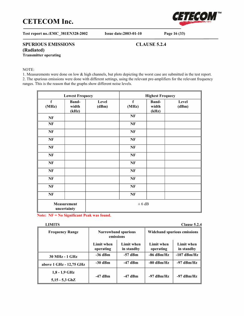
SPURIOUS EMISSIONS CLAUSE 5.2.4 (Radiated) Transmitter operating NOTE: 1. Measurements were done on low & high channels, but plots depicting the worst case are submitted in the test report. 2. The spurious emissions were done with different settings, using the relevant pre-amplifiers for the relevant frequency ranges. This is the reason that the graphs show different noise levels.
Lowest Frequecy Highest Frequecy f
(MHz) Band- width (kHz)
Level (dBm)
f (MHz)
Band- width (kHz)
Level (dBm)
NF NF NF NF NF NF NF NF NF NF NF NF NF NF NF NF NF NF NF NF NF NF
Measurement uncertainty
± 6 dB
Note: NF = No Significant Peak was found.
LIMITS Clause 5.2.4
Narrowband spurious emissions
Wideband spurious emissions Frequency Range
Limit when operating
Limit when in standby
Limit when operating
Limit when in standby
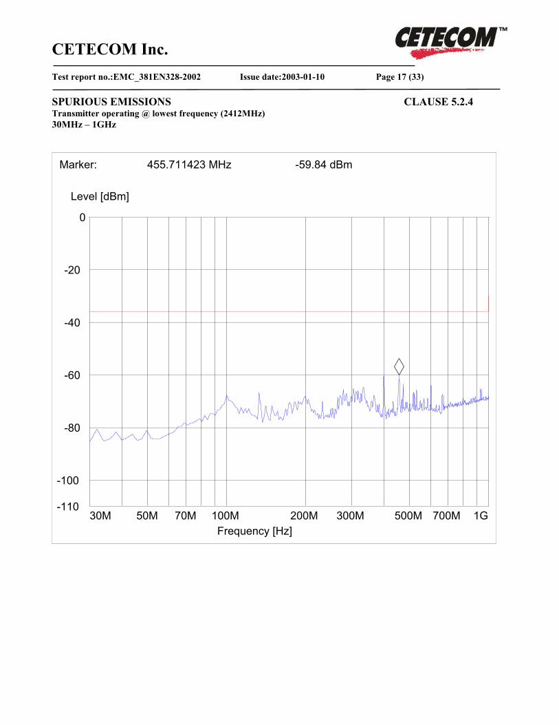
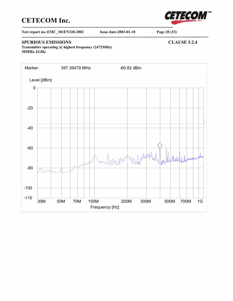
30 MHz - 1 GHz -36 dBm -57 dBm -86 dBm/Hz -107 dBm/Hz
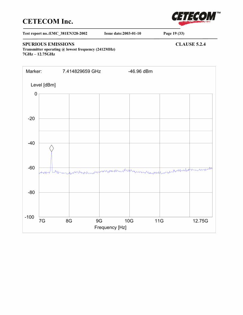
above 1 GHz - 12,75 GHz -30 dBm -47 dBm -80 dBm/Hz -97 dBm/Hz
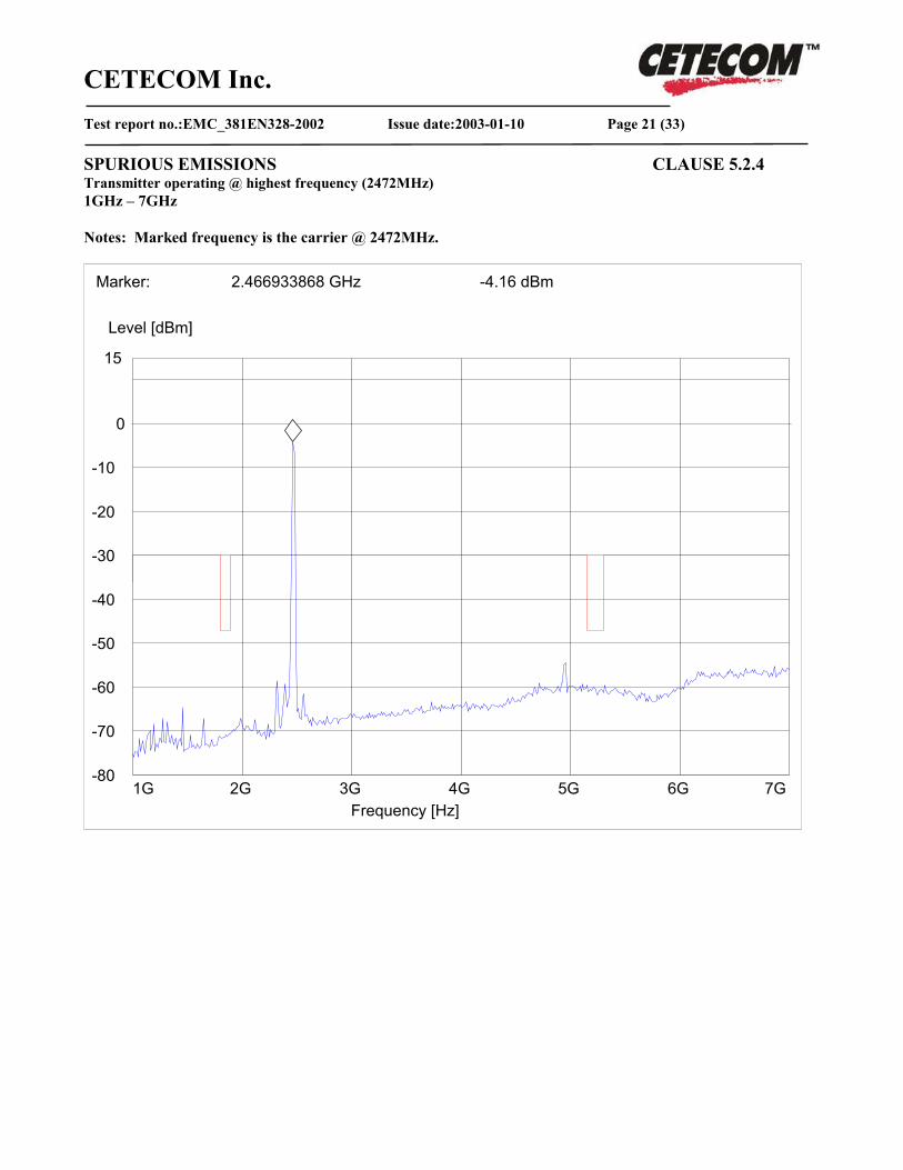
1,8 - 1,9 GHz
5,15 - 5,3 GhZ
-47 dBm
-47 dBm
-97 dBm/Hz
-97 dBm/Hz
CETECOM Inc. Test report no.:EMC_381EN328-2002 Issue date:2003-01-10 Page 17 (33)
SPURIOUS EMISSIONS CLAUSE 5.2.4 Transmitter operating @ lowest frequency (2412MHz) 30MHz – 1GHz
-110
-100
-80
-60
-40
-20
0
Level [dBm]
30M 50M 70M 100M 200M 300M 500M 700M 1GFrequency [Hz]
Marker: 455.711423 MHz -59.84 dBm

CETECOM Inc. Test report no.:EMC_381EN328-2002 Issue date:2003-01-10 Page 18 (33)
SPURIOUS EMISSIONS CLAUSE 5.2.4 Transmitter operating @ lowest frequency (2412MHz) 1GHz – 7GHz Notes: Marked frequency is the carrier @ 2412MHz.
-80
-70
-60
-50
-40
-30
-20
-10
0
15
Level [dBm]
1G 2G 3G 4G 5G 6G 7GFrequency [Hz]
Marker: 2.418837675 GHz -4.23 dBm
CETECOM Inc. Test report no.:EMC_381EN328-2002 Issue date:2003-01-10 Page 19 (33)
SPURIOUS EMISSIONS CLAUSE 5.2.4 Transmitter operating @ lowest frequency (2412MHz) 7GHz – 12.75GHz
-100
-80
-60
-40
-20
0
Level [dBm]
7G 8G 9G 10G 11G 12.75GFrequency [Hz]
Marker: 7.414829659 GHz -46.96 dBm
CETECOM Inc. Test report no.:EMC_381EN328-2002 Issue date:2003-01-10 Page 20 (33)
SPURIOUS EMISSIONS CLAUSE 5.2.4 Transmitter operating @ highest frequency (2472MHz) 30MHz-1GHz
-110
-100
-80
-60
-40
-20
0
Level [dBm]
30M 50M 70M 100M 200M 300M 500M 700M 1GFrequency [Hz]
Marker: 397.39479 MHz -60.82 dBm
CETECOM Inc. Test report no.:EMC_381EN328-2002 Issue date:2003-01-10 Page 21 (33)
SPURIOUS EMISSIONS CLAUSE 5.2.4 Transmitter operating @ highest frequency (2472MHz) 1GHz – 7GHz Notes: Marked frequency is the carrier @ 2472MHz.
-80
-70
-60
-50
-40
-30
-20
-10
0
15
Level [dBm]
1G 2G 3G 4G 5G 6G 7GFrequency [Hz]
Marker: 2.466933868 GHz -4.16 dBm

CETECOM Inc. Test report no.:EMC_381EN328-2002 Issue date:2003-01-10 Page 22 (33)
SPURIOUS EMISSIONS CLAUSE 5.2.4 Transmitter operating @ highest frequency (2472MHz) 7GHz – 12.75GHz
-100
-80
-60
-40
-20
0
Level [dBm]
7G 8G 9G 10G 11G 12.75GFrequency [Hz]
Marker: 7.414829659 GHz -46.96 dBm
CETECOM Inc. Test report no.:EMC_381EN328-2002 Issue date:2003-01-10 Page 23 (33)
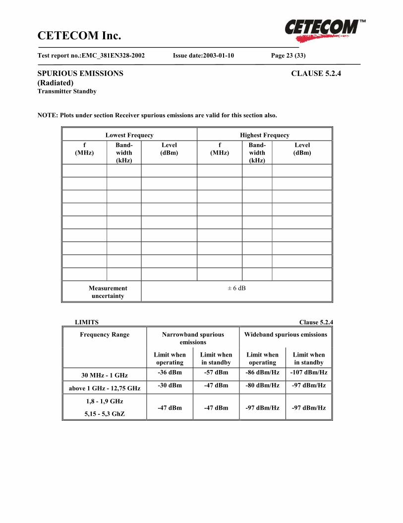
SPURIOUS EMISSIONS CLAUSE 5.2.4 (Radiated) Transmitter Standby NOTE: Plots under section Receiver spurious emissions are valid for this section also.
Lowest Frequecy Highest Frequecy f
(MHz) Band- width (kHz)
Level (dBm)
f (MHz)
Band- width (kHz)
Level (dBm)
Measurement uncertainty
± 6 dB
LIMITS Clause 5.2.4
Narrowband spurious emissions
Wideband spurious emissions Frequency Range
Limit when operating
Limit when in standby
Limit when operating
Limit when in standby
30 MHz - 1 GHz -36 dBm -57 dBm -86 dBm/Hz -107 dBm/Hz
above 1 GHz - 12,75 GHz -30 dBm -47 dBm -80 dBm/Hz -97 dBm/Hz
1,8 - 1,9 GHz
5,15 - 5,3 GhZ
-47 dBm
-47 dBm
-97 dBm/Hz
-97 dBm/Hz
CETECOM Inc. Test report no.:EMC_381EN328-2002 Issue date:2003-01-10 Page 24 (33)
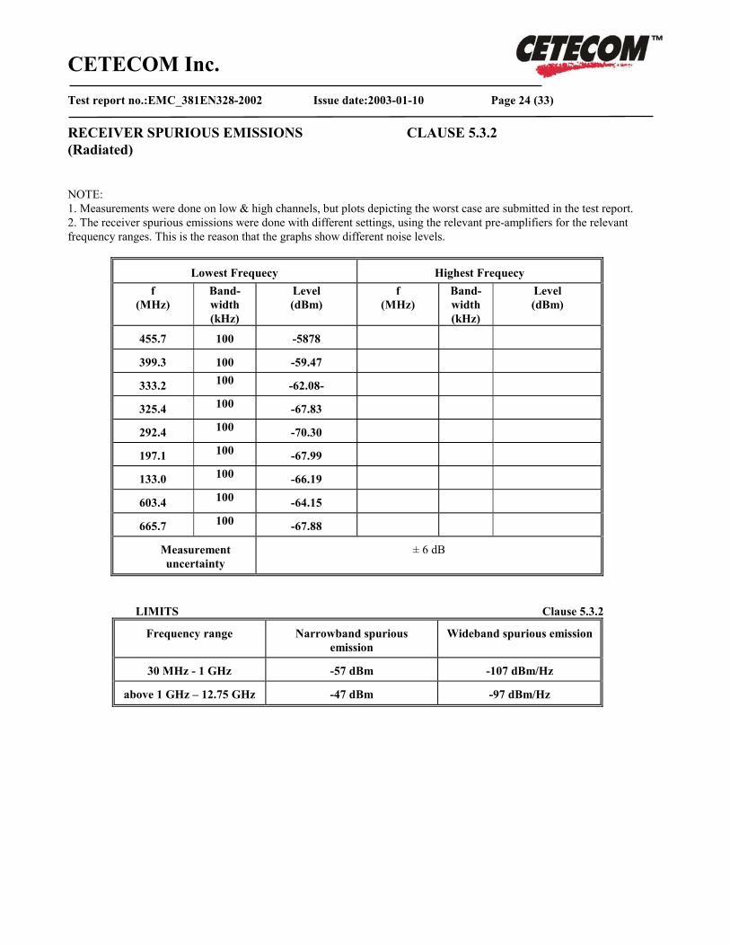
RECEIVER SPURIOUS EMISSIONS CLAUSE 5.3.2 (Radiated) NOTE: 1. Measurements were done on low & high channels, but plots depicting the worst case are submitted in the test report. 2. The receiver spurious emissions were done with different settings, using the relevant pre-amplifiers for the relevant frequency ranges. This is the reason that the graphs show different noise levels.
Lowest Frequecy Highest Frequecy f
(MHz) Band- width (kHz)
Level (dBm)
f (MHz)
Band- width (kHz)
Level (dBm)
455.7 100 -5878
399.3 100 -59.47
333.2 100 -62.08-
325.4 100 -67.83
292.4 100 -70.30
197.1 100 -67.99
133.0 100 -66.19
603.4 100 -64.15
665.7 100 -67.88
Measurement uncertainty
± 6 dB
LIMITS Clause 5.3.2
Frequency range Narrowband spurious emission
Wideband spurious emission
30 MHz - 1 GHz -57 dBm -107 dBm/Hz
above 1 GHz – 12.75 GHz -47 dBm -97 dBm/Hz
CETECOM Inc. Test report no.:EMC_381EN328-2002 Issue date:2003-01-10 Page 25 (33)
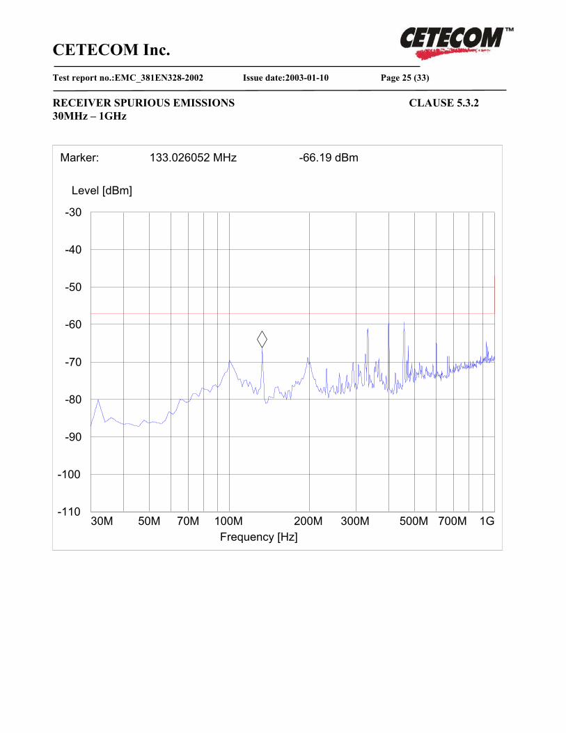
RECEIVER SPURIOUS EMISSIONS CLAUSE 5.3.2 30MHz – 1GHz
-110
-100
-90
-80
-70
-60
-50
-40
-30
Level [dBm]
30M 50M 70M 100M 200M 300M 500M 700M 1GFrequency [Hz]
Marker: 133.026052 MHz -66.19 dBm

CETECOM Inc. Test report no.:EMC_381EN328-2002 Issue date:2003-01-10 Page 26 (33)
RECEIVER SPURIOUS EMISSIONS CLAUSE 5.3.2 1GHz – 7GHz
-100
-80
-60
-40
-20
0
Level [dBm]
1G 2G 3G 4G 5G 6G 7GFrequency [Hz]
Marker: 1.276553106 GHz -66.44 dBm
CETECOM Inc. Test report no.:EMC_381EN328-2002 Issue date:2003-01-10 Page 27 (33)
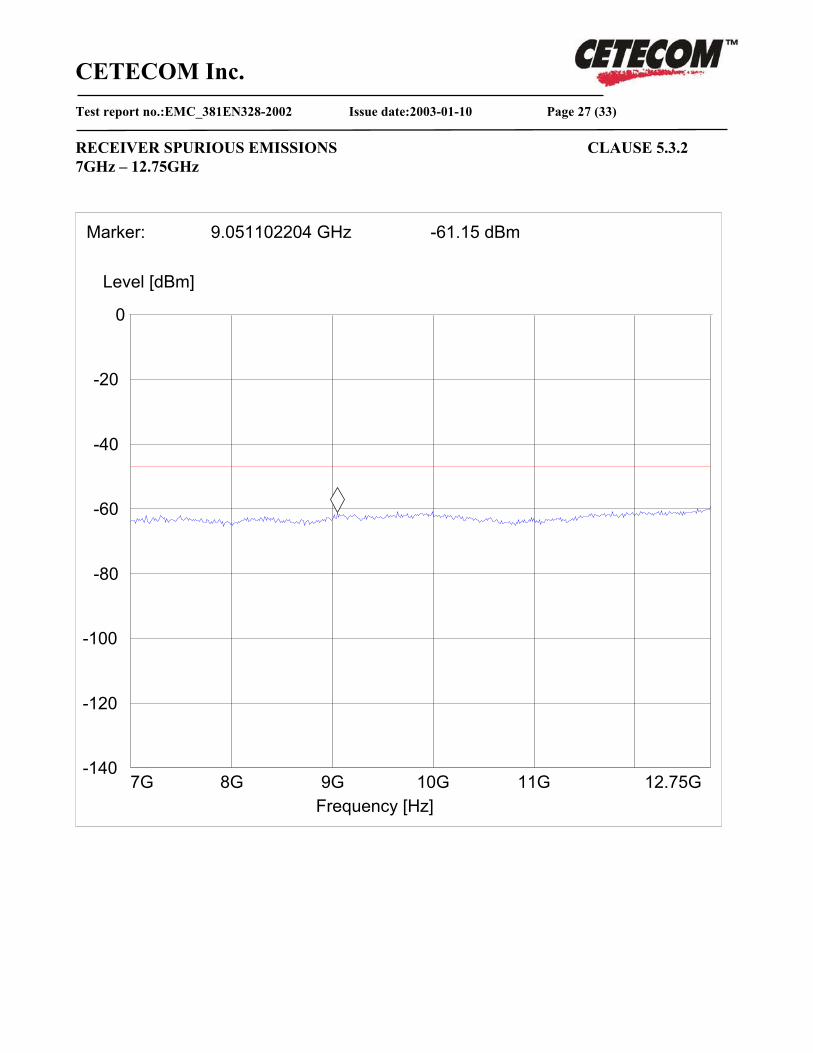
RECEIVER SPURIOUS EMISSIONS CLAUSE 5.3.2 7GHz – 12.75GHz
-140
-120
-100
-80
-60
-40
-20
0
Level [dBm]
7G 8G 9G 10G 11G 12.75GFrequency [Hz]
Marker: 9.051102204 GHz -61.15 dBm
CETECOM Inc. Test report no.:EMC_381EN328-2002 Issue date:2003-01-10 Page 28 (33)
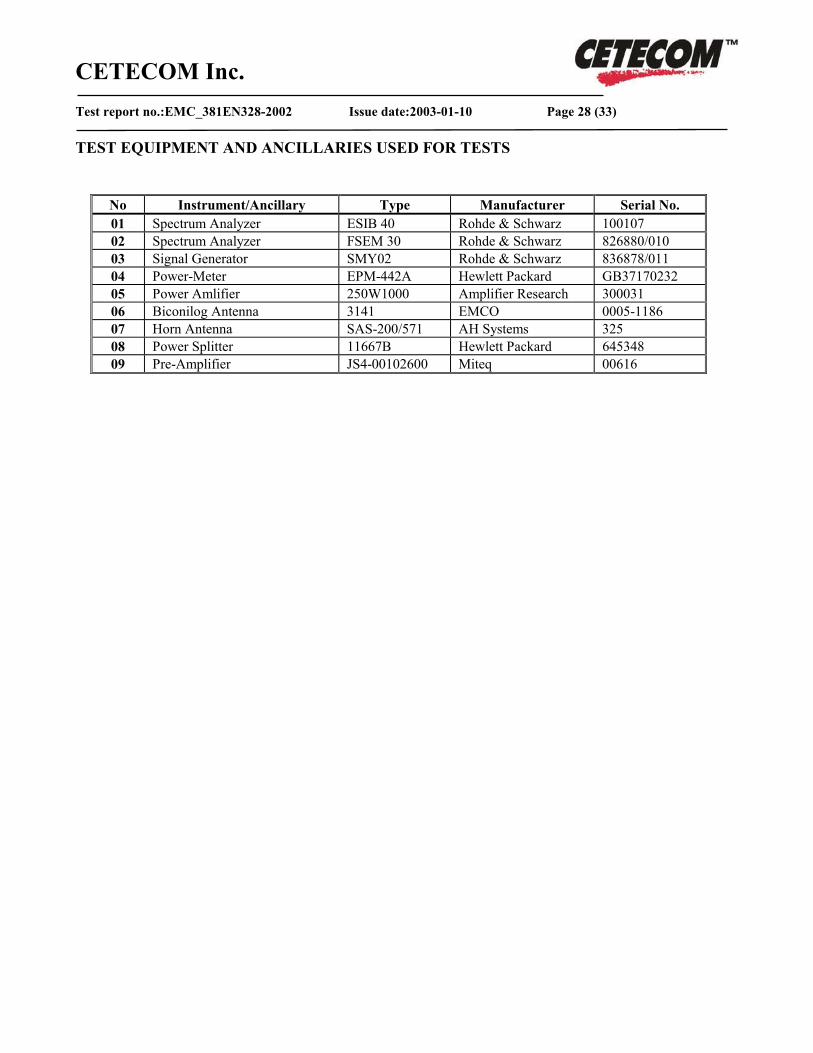
TEST EQUIPMENT AND ANCILLARIES USED FOR TESTS
No Instrument/Ancillary Type Manufacturer Serial No. 01 Spectrum Analyzer ESIB 40 Rohde & Schwarz 100107 02 Spectrum Analyzer FSEM 30 Rohde & Schwarz 826880/010 03 Signal Generator SMY02 Rohde & Schwarz 836878/011 04 Power-Meter EPM-442A Hewlett Packard GB37170232 05 Power Amlifier 250W1000 Amplifier Research 300031 06 Biconilog Antenna 3141 EMCO 0005-1186 07 Horn Antenna SAS-200/571 AH Systems 325 08 Power Splitter 11667B Hewlett Packard 645348 09 Pre-Amplifier JS4-00102600 Miteq 00616
CETECOM Inc. Test report no.:EMC_381EN328-2002 Issue date:2003-01-10 Page 29 (33)
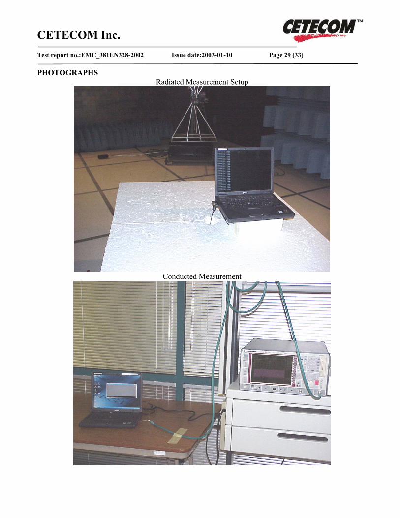
PHOTOGRAPHS Radiated Measurement Setup
Conducted Measurement
CETECOM Inc. Test report no.:EMC_381EN328-2002 Issue date:2003-01-10 Page 30 (33)
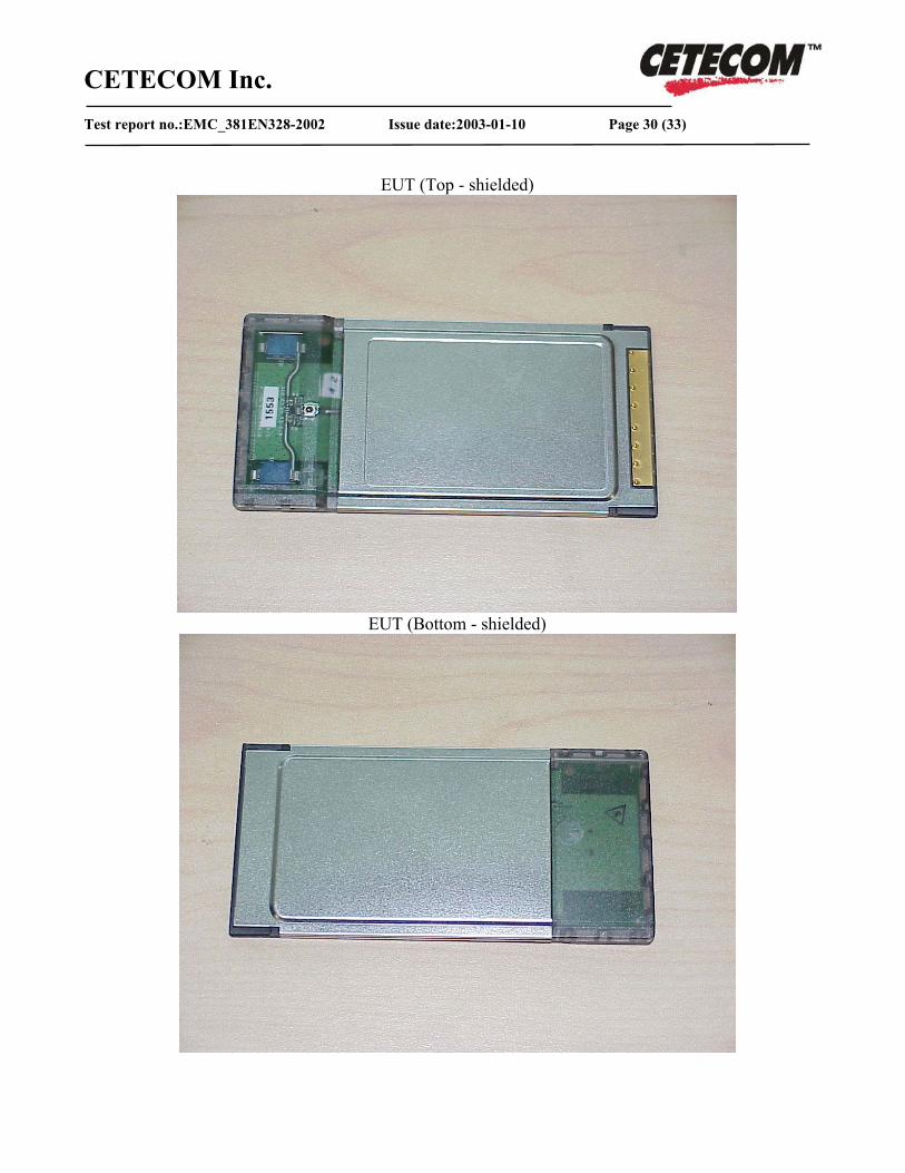
EUT (Top - shielded)
EUT (Bottom - shielded)
CETECOM Inc. Test report no.:EMC_381EN328-2002 Issue date:2003-01-10 Page 31 (33)
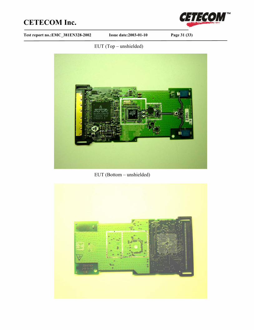
EUT (Top – unshielded) EUT (Bottom – unshielded)
CETECOM Inc. Test report no.:EMC_381EN328-2002 Issue date:2003-01-10 Page 32 (33)
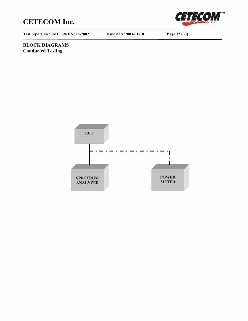
BLOCK DIAGRAMS Conducted Testing
EUT
SPECTRUM ANALYZER
POWER METER

CETECOM Inc. Test report no.:EMC_381EN328-2002 Issue date:2003-01-10 Page 33 (33)
Radiated Testing
Turn Table
EUT Antenna
Measurement Antenna
ANECHOIC CHAMBER
Spectrum Analyzer