Embed Size (px)
Citation preview

Page 1
DEMOCRATIC SOCIALIST REPUBLIC OF SRI LANKA
CEYLON ELECTRICITY BOARD
NATIONAL GRID DEVELOPMENT PROJECT
LOAN AGREEMENT NO:
SHORT INITIAL ENVIRONMENTAL
EXAMINATION
ENVIRONMENT UNIT CEYLON ELECTRICITY BOARD COLOMBO SRI LANKA
March 2008

Page 2
Abbreviations
ADB - Asian Development Bank CDM - Clean Development Mechanism CEA - Central Environmental Authority CEB - Ceylon Electricity Board db(A) - A-weighted sound measurement in decibels DS - Divisional Secretary EIA - Environmental Impact Assessment EPL - Environmental Protection License GIS - Gas Insulated Substation GN - Grama Niladhari GS - Grid Substation IEC - International Electrotechnical Commission IEE - Initial Environmental Examination IPP - Independent Power Producer km - kilometer kV - kilovolt LoI - Letter of Intent m - meter MVA - Megavolt Ampere MW - Megawatt NCRE - Non-Conventional Renewable Energy NEA - National Environment Act PSS/e - Power System Simulation REA - Rapid Environmental Assessment ROW - Right of Way SEA - Sustainable Energy Authority SCC - System Control Centre SLBC - Sri Lanka Broadcasting Corporation SPPA - Small Power Purchase Agreement SPP - Small Power Producer VRR - Victoria, Randenigala, Rantembe
Page 3
CONTENTS
1 INTRODUCTION 5 1.1 Subproject 1: The System Control Centre 5 1.2 Subproject 2: Grid Constraints to Absorb SPPs 6 1.3 Subproject 3: Other Constraints in the Grid 8
2 DESCRIPTION OF THE PROJECT 8 2.1 Subproject 1: The New System Control Centre 9 2.2 Subproject 2: Augmentation of GSs to Absorb Renewable Energy 9 2.3 Subproject 3: Grid Strengthening 10 2.4 Type of Project and the Category 13
3 DESCRIPTION OF THE ENVIRONMENT 13 3.1 The New System Control Centre 15 3.2 Grid Substations to be Augmented 15
3.2.1 Subproject 2 15 3.2.2 Subproject 3 16
3.3 New Grid Substations 17 3.4 New 132 kV Transmission Lines 18
3.4.1 Galle- Matara Line 18 3.4.2 Habarana-Valachchenai Line 19 3.4.3 Puttalam-Maho Line 20 3.4.4 Ukuwela-Pallekelle Line 21 3.4.5 Proposed In and Out Connection at Naula 22
4 POTENTIAL ENVIRONMENTAL IMPACTS AND MITIGATION MEASURES 22 4.1 New System Control Centre 22 4.2 Grid Substations to be Augmented 22
4.2.1 Potential Environmental Impacts and Mitigatory Measures 22 4.3 Transmission Lines 24
4.3.1 Potential Environmental Impacts and Mitigatory Measures 24
5 INSTITUTIONAL REQUIREMENTS AND ENVIRONMENTAL MONITORING PLAN 26
6 PUBLIC CONSULTATION AND INFORMATION DISCLOSURE 37 6.1 Grid Substations 37 6.2 Right-of-Way of the Transmission Lines 37
6.2.1 Preliminary Work Conducted 37 6.2.2 Sri Lanka Environmental Approval Process 38 6.2.3 The Detailed Survey 40 6.2.4 Information Disclosure 40 6.2.5 Public Consultation and Appeal Procedure 41

Page 4
6.3 Procedure to Handle Public Complaints During Implementation Phase 41
7 FINDINGS AND RECOMMENDATIONS 42 7.1 Environmental Impacts of the new SCC, GS Augmentation and New GSs 42 7.2 Transmission Lines 42
8 CONCLUSIONS 42
LIST OF FIGURES
Figure 1.1 - CEB Existing Transmission System 2007 7
Figure 2.1 - Sri Lanka Transmission Map (2011) Showing the Elements of the Project 12
Figure 3.1- Space Available for the Augmentation of GSs 14
LIST OF TABLES
Table 2.1 - Summary Scope of the Subproject 9
Table 2.2- Summary Scope of the Subproject 10
Table 4.1- Land-use Along the Transmission Lines 24
Table 5.1 - Environmental Monitoring Plan 28

Page 5
1 INTRODUCTION The project proponent, The Ceylon Electricity Board (CEB) is the national electricity utility in Sri Lanka responsible for generation and transmission of electricity in the country, and is also responsible for the distribution and supply of electricity to about 90% of the customers. The transmission system comprises 220 kV and 132 kV transmission lines interconnecting Grid Substations (GSs) and power stations. By end 2006, the CEB transmission system consisted of 50 grid substations and about 2050 km of transmission lines. The existing transmission network and the GSs are shown in Figure 1.1. Based on CEB’s 10-year regional demand forecasts, and the annually updated generation expansion plan, CEB’s Transmission Planning Branch prepares a 10-year transmission plan. This plan is updated every year. This plan is prepared at a national level and is a comprehensive plan, using tools such as Power System Simulation Software (PSS/e), and provides information with regard to security analysis, stability, fault levels and reliability of the system. This Short Initial Environmental Examination (SIEE) provides an insight into the expected environmental issues of the project, impacts, mitigatory measures and the implementation/monitoring mechanism to ensure that mitigatory measures are implemented. For the purpose of this SIEE, The Nation Grid Development Project is divided into three subprojects, as follows: Subproject 1: New System Control Centre Subproject 2: Augmentation of Grid Substations for the Absorption of Renewable Energy Subproject 3: Augmentation of Eight Grid Substations, Construction of Three New Grid Substations and Construction of Four New Transmission Lines
1.1 Subproject 1: The System Control Centre CEB’s existing System Control Cenre (SCC) was established in late 1980s, at Kent Road, Colombo 9. The limitations and need for expansion of the facilities at the SCC have been felt from mid 1990s. A study was commissioned recently1, which highlighted that the present SCADA system at SCC has the following shortcomings and inefficiencies.
• The existing SPIDER Micro SCADA is principally designed for small-scale distribution automation and is not suitable for supervision of the nationwide power transmission system.
• At present, only about one third of power stations and substations of the transmission system are supervised by the SCC. The existing SCC cannot be extended to supervise the entire power system.
• Network Security Analysis (NSA) and Energy Management (EMS) software packages required to improve the safety of network operation and to optimise operation of the power system cannot be implemented in the existing system.
1 “Feasibility Study For System Control Centre, Sri Lanka”, FICHTNER.
Page 6
• The existing hardware as well as the existing RTUs at the outstations are obsolete and have reached or exceeded their normal lifetime. The hardware and particularly the RTUs are not supported anymore and spare parts are either not available at all or difficult and expensive to obtain.
• The existing communication network consisting mainly of obsolete and aged analog Power Line Carrier equipment does not provide sufficient communication channels/ capacity required for efficient power system operation.
The feasibility report thus concludes that the existing SCADA system cannot be extended and has to be replaced. At the same time, the feasibility study report recommends the following expansion to ensure continued efficient real time operation.
• Extend supervision from the SCC to larger parts of the network by incorporation of all major power stations and grid substations into SCC.
• Respective software packages should be added for optimum operation of the transmission network and energy management.
1.2 Subproject 2: Grid Constraints to Absorb SPPs In addition to the transmission development requirements identified in regular transmission planning exercises focused on meeting customer needs, additional requirements have emerged owing to the rapid development of grid-connected power plants based on Non-conventional Renewable Energy (NCRE) sources. Small Power Producers (SPPs) use NCRE sources in power plants less than 10 MW. Further to the 63 SPPs already in operation, CEB has signed 37 SPPAs (35 of which are small hydro), which are in various stages of development. In addition to all the above, a further 96 Letters of Intent (LOIs, of which 69 are for small hydro) have been issued by CEB. As it is evident from the above, investors are eager to invest in NCRE-based power generation projects in Sri Lanka under the SPPA mechanism, and this power purchase scheme has a very high potential of further enhancing the development of renewable energy for electricity generation. The Government’s 10-year development plan and the National Energy Policy of Sri Lanka state that the country will endeavor to reach a 10% target of electricity generation from NCRE sources by year 2015. Sri Lanka’s small hydroelectric potential is centered on three provinces: Central, Sabaragamuwa and Uva. CEB has twelve GSs located in these three provinces, and adjacent provinces, to which hydroelectric SPPs are connected: Badulla, Balangoda, Deniyaya, Kiribathkumbura, Kosgama, Mathugama, Nuwara Eliya, Rantembe, Seethawaka, Ratnapura, Ukuwela, Wimalasurendra. Out of these twelve GSs, CEB is no longer issuing LoIs for small hydro SPPs to be connected to the following nine GSs, owing to the firm capacity being exceeded by the LoIs/SPPAs already active: Badulla, Balangoda, Deniyaya, Nuwara Eliya, Rantembe, Seethawaka, Ratnapura, Ukuwela, Wimalasurendra. Out of the above, the capacity constraint at Deniyaya is being relieved through another project.

Page 7
Figure 1.1 - CEB Existing Transmission System 2007
EMBILIPITIYA
MATARA
GALLE
DENIYAYA
SAMANALAWEWA
BALANGODA
MATUGAMA
PANADURA
RANTEMBE
RANDENIGALA
VICTORIA
INGINIYAGALA
AMPARA
BOWATENNA
UKUWELA
KIRIBATHKUMBURA
KOTMALE
WIMALASURENDRABADULLA
N'ELIYA
MADAMPE
BOLAWATTA
THULHIRIYA
KURUNEGALA
VEYANGODA
BIYAGAMA
ORUWALA
KOLONNAWA
KOTUGODA
RATMALANA PANNIPITIYA
TRINCOMALEE
ANURADHAPURA
PUTTALAM HABARANA
RATMALANA
PANNIPITIYA
ORUWALA
BIYAGAMA
FORT
KOLLUPITIYA
KOLONNAWA
S'KANDA
132kV : Underground Cable132kV Line
220kV Line
POLPITIYA
NEWLAXAPANA
CANYON
RATNAPURA
KELANIYA
KOTUGODA
SAPUGASKANDA
KELANITISSA
KHD
ATURUGIRIYA
KOSGAMA
ATURUGIRIYA
VAVUNIA
HAMBANTOTA
LAKDANAWI
LAXAPANA
KUKULE
HORANA
SITHAWAKA
220/132 kV Sub Station 132kV GS Hydro Power Station Thermal Power Station
NEW ANURADHAPURABARGE PS
KELANITISSA
CHUNNAKAM
KILINOCHCHI
VALACHCHANAI
132kV Line (not in operation)
SRI JAYAWARDHANAPURA
MARADANA
HAVELOCK TOWN
DEHIWALA

Page 8
LoIs are no longer issued by CEB to prospective small power producers whose small hydro developments would feed power to any of these eight GSs. In this project, CEB proposes to expand the capacity of seven of the eight grid substations within the existing GS premises themselves. The expansion of one GS (Rantembe) will not be at the same site but will be associated with a new transmission line and a new GS built at Mahiyangana. In general, the absorption capacity of each GS presently limited to 25 W will be raised to 50 MW with the proposed capacity expansion.
1.3 Subproject 3: Other Constraints in the Grid Grid strengthening is a continuous activity in a system where demand growth is about 7% per year, to provide capacity for expanding rural electrification networks, and to improve the quality of supply to already connected customers, both rural and sub-urban. Augmentation of the grid substations in Ampara, Habarana, Kurunegala, Valachchenai and Veyangoda specifically address the capacity requirements to improve the service to predominantly rural customers. Ampara GS and Valachchenai GS serve improve the service to vast areas of the Eastern Province, serving predominantly rural customers in the province which has lower electrification rate, who are presently served with a capacity constraint. New GSs at Maho and Naula have been proposed to serve predominantly rural areas in the North western and Central provinces, respectively, and to improve the quality of supply to existing rural customers and provide capacity to serve new customers in the two provinces, and in the adjoining provinces. Capacity expansion at Horana GS and the new Pallekelle GS is required to serve the adjoining industrial zones, as well as the retail customers in the areas, which remain predominantly rural. Matara and Panadura GSs serve suburban customers of all types and augmentation is required to strengthen the capacity and to improve reliability to these customers. Two new transmission lines are required to be built under this sub-project to serve the new GSs at Maho and Pallekelle. The Habarana-Valachchenai line, along with the augmentation of the Valachchenai GS is required to increase the capacity to serve the northern sector of the Eastern province. The fourth transmission line under this project, Galle-Matara, is required to improve the reliability of the service to both Galle and Matara, both of which are rapidly growing. The necessity and the capacity of all the GS developments and new transmission lines have been identified by extensive planning studies conducted over the past few years, and many of the developments proposed under this project are already behind schedule.
2 DESCRIPTION OF THE PROJECT The project consists of building a new System Control Centre at Sri Jayewardenepura, augmenting five GSs and building one new GS to absorb renewable energy, and the augmentation for a further eight GSs, construction of three new GSs and four new transmission lines.

Page 9
All GSs and transmission lines operate at 132 kV. The transmission line corridor will be 27 m. The project implementation will be in years 2008, 2009 and 2010.
2.1 Subproject 1: The New System Control Centre A new SCC will be built at Sri Jayewardenepura. The summarised scope of work is give below:
(a) Construction of the Masterstation, which includes the control centre building, support facilities, computer hardware, application software and communication interfaces.
(b) Data acquisition and adaptation work in substations and power plants including Remote Terminal Units (RTUs), adaptation control, indications, protection and other station systems and transmission protocols.
(c) Installation of communication equipment, including voice communication, Power Line Carrier (PLC), fiber optic cables and equipment and other modes.
2.2 Subproject 2: Augmentation of GSs to Absorb Renewable Energy Table 2.1 summarises the existing capacity and the status after augmentation, at the eight GSs. The Sri Lanka map with the relevant GS covered in this subproject, is shown later, in Figure 2.5.
Table 2.1 - Summary Scope of the Subproject
Grid Substation Purpose of
Original Design
Existing Transformer
Capacity
Esixting Firm
Capacity (MW)
Proposed Investment
Transformer Capacity after the Proposed Investment
New Firm Capacity
(MW)
1 Balangoda Grid substation
2 x 31.5 MVA 25 Augment with one 31.5 MVA
transformer
3 x 31.5 MVA 50
2 Nuwara Eliya Grid substation
2 x 31.5 MVA 25 Augment with one 31.5 MVA
transformer
3 x 31.5 MVA 50
3 Seethawaka Grid substation
2 x 31.5 MVA 25 Augment with one 31.5 MVA
transformer
3 x 31.5 MVA 50
4 Ukuwela Generation substation + grid substation
2 x 31.5 MVA 25 Augment with one 31.5 MVA
transformer
3 x 31.5 MVA 50
5 Badulla Generation substation + grid substation
2 x 31.5 MVA 25 Augment with one 31.5 MVA Transformer
3 x 31.5 MVA
50
Page 10
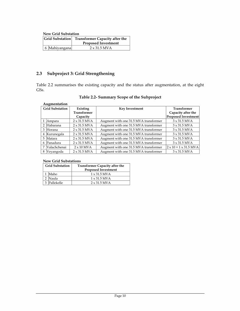
New Grid Substation Grid Substation Transformer Capacity after the
Proposed Investment 6 Mahiyangana 2 x 31.5 MVA
2.3 Subproject 3: Grid Strengthening Table 2.2 summarises the existing capacity and the status after augmentation, at the eight GSs.
Table 2.2- Summary Scope of the Subproject Augmentation Grid Substation Existing
Transformer Capacity
Key Investment Transformer Capacity after the
Proposed Investment 1 Ampara 2 x 31.5 MVA Augment with one 31.5 MVA transformer 3 x 31.5 MVA 2 Habarana 2 x 31.5 MVA Augment with one 31.5 MVA transformer 3 x 31.5 MVA 3 Horana 2 x 31.5 MVA Augment with one 31.5 MVA transformer 3 x 31.5 MVA 4 Kurunegala 2 x 31.5 MVA Augment with one 31.5 MVA transformer 3 x 31.5 MVA 5 Matara 2 x 31.5 MVA Augment with one 31.5 MVA transformer 3 x 31.5 MVA 6 Panadura 2 x 31.5 MVA Augment with one 31.5 MVA transformer 3 x 31.5 MVA 7 Valachchenai 2 x 10 MVA Augment with one 31.5 MVA transformer 2 x 10 + 1 x 31.5 MVA 8 Veyangoda 2 x 31.5 MVA Augment with one 31.5 MVA transformer 3 x 31.5 MVA
New Grid Substations
Grid Substation Transformer Capacity after the Proposed Investment
1 Maho 1 x 31.5 MVA 2 Naula 1 x 31.5 MVA 3 Pallekelle 2 x 31.5 MVA

Page 11
New Transmission Lines
Line Description 1 Galle-Matara 132 kV double circuit line, 34 km 2 Habarana-
Valachchenai 132 kV double circuit line, single
circuit stringing, 100 km 3 Puttalam-
Maho 132 kV double circuit, single circuit
stringing, 42 km 4 Ukuwela-
Pallekelle 132 kV double circuit line, 18 km
5 Naula in and out connection
Short 132 kV double circuit line, 0.5 km
The Sri Lanka map with the relevant GSs covered in project, is shown in Figure 2.1.

Page 12
Figure 2.1 - Sri Lanka Transmission Map (2011) Showing the Elements of the Project
NEW ANURADHAPURA
EMBILIPITIYA
MATARAGALLE
DENIYAYA
SAMANALAWEWA
BALANGODA
MATUGAMA
PANADURA
RANTEMBE
RANDENIGALA
VICTORIA
INGINIYAGALA
AMPARA
BOWATENNA
UKUWELA
KIRIBATHKUMBURA
KOTMALE
WIMALASURENDRABADULLA
N'ELIYA
MADAMPE
BOLAWATTA
THULHIRIYA
KURUNEGALA
VEYANGODA
BIYAGAMA
KOLONNAWA
KOTUGODA
RATMALANA PANNIPITIYA
TRINCOMALEE
ANURADHAPURA
PUTTALAM HABARANA
RATMALANA
PANNIPITIYA
ORUWALA
BIYAGAMA
FORT
KOLLUPITIYA
KELANITISSA
KOLONNAWA
S'KANDA
132kV : Underground Cable132kV Line
220kV Line
POLPITIYA
NEWLAXAPANA
CANYON
RATNAPURA
ANIYAKANDA
KELANIYA
KOTUGODA
SAPUGASKANDA
KELANITISSA
KHD
ATURUGIRIYA
KOSGAMA
ATURUGIRIYA
VAVUNIA
POLONNARUWA
PANNALA
AMBALANGODA
HAMBANTOTA
KERAWALAPITIYA
MEDAGAMA
PALLEKELE
LAXAPANA
KATANA
KUKULE
HORANA
SITHAWAKADEHIWALA
SRI J'PURA
ANIYAKANDAKERAWALAPITIYA
DEHIWALA
MARADANA
220/132 kV Sub Station 132kV GS Hydro Power Station Thermal Power Station
HAVELOCK TOWN
NAULA
KOTAHENA
KEGALLE
BARGE PS
KILINOCHCHI
CHUNNAKAM
VALACHCHANAI
PADDIRIPPU
SUB B
MAHOSRI J'PURA
BELIATTA
PUTTLAM PS
220kV UG Cable
MAHIYANGANE
ORUWALA
GSs to absorb renewable energy New Lines to be built
New GSs to be built
Other GSs to be augmented

Page 13
2.4 Type of Project and the Category This project consists of augmentation of thirteen existing GSs, building four new GSs, and building five new transmission lines over newly established rights-of-way. According to the ADB Environmental Assessment Guidelines2 (clause 142), this subproject can be classified as follows: Project type: Electrical Transmission Category: B
3 DESCRIPTION OF THE ENVIRONMENT Information in this section is presented for groups of substations where appropriate, to avoid repetition of common information. Wherever special situations exist, they are separately stated. A key feature of the proposed subproject is that thirteen GSs to be augmented in this project will be at the present premises, within the available land space already owned by CEB, with no additional land to be acquired. A selection of the GSs showing the space available is shown in Figure 3.1.
2 Environmental Assessment Guidelines, Asian Development Bank, 2003.

Page 14
Figure 3.1- Space Available for the Augmentation of GSs
Balangoda
Horana Kurunegala
Nuwara Eliya
Panadura Veyangoda

Page 15
3.1 The New System Control Centre Available infrastructure facilities: Sri Jayewardenepura is the administrative capital of Sri Lanka, and is linked to the commercial capital Colombo, and to other towns in the western province through a network of highways. The location is within the Municipal Council limits, and has all the facilities of an urban centre. For other information on social and economic infrastructure, please see the information in the section on subproject 2 relevant to Colombo District.
3.2 Grid Substations to be Augmented
3.2.1 Subproject 2 Available Infrastructure Facilities: A-class roads link Badulla with major cities such as Nuwara Eliya, Monaragala, Wellawaya and Balangoda while the railway line also links Badulla with the main city Colombo. Balangoda is linked to Ratnapura, Badulla and Wellawaya through A-class roads while Nuwara Eliya is connected to Kandy, Badulla and Avissawella. Railway network also reaches Nuwara Eliya at Nanu-oya, about 15km from the grid substation location. Sithawaka is accessible through both A-class roads and rail and is located within the district of Colombo itself. Ukuwela GS is located within their respective power plant premises or in close proximity, which are connected to the main road network through B class roads. The primary mode of transportation in all the areas where the grid substations are located is road vehicles. None of these grid substations are close to the main ports or airports of the country. Locations of grid substations and a wide surrounding area have grid electricity supply. Water is also available abundantly in these areas as none of these GSs are located in the dry zone of the country. The wet climate and mountainous topography of the locality provides with ample water resources. In general, the infrastructure availability of the locality of all GSs considered in this report is reasonably good. Industrial Activities: The level of industrial activities in most of the areas in discussion is very low. Except for Sithawaka, where it is declared as an industrial zone, all other areas have minimal industrial activities. Gem industry in Sithawaka and Balangoda has brought in prosperity to these three areas while vegetable farming has been the main source of income generation for Nuwara Eliya area. Ukuwela GS located in Matale and Nuwaraeliya districts, respectively, is a predominantly tea-growing area with considerable income coming from agriculture (paddy and vegetable) as well. Salient feature of all the GSs are the absence of large-scale industries, which are mostly confined to Colombo and other locations in the Western province. Land Use: Use of Land in all these areas is predominantly for agricultural purposes while the balance is either residential or unused. A good portion of the land area consist of mountainous terrain not suitable for any purpose other than agriculture. Badulla, Balangoda, Nuwara Eliya and Ukuwela are areas with vast tea land spread across, while Balangoda and Sithawaka also have rubber estates. Paddy is commonly available in all the above areas, except Nuwara Eliya.
Page 16
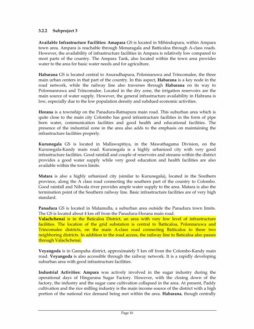
3.2.2 Subproject 3 Available Infrastructure Facilities: Amapara GS is located in Mihindupura, within Ampara town area. Ampara is reachable through Monaragala and Batticaloa through A-class roads. However, the availability of infrastructure facilities in Ampara is relatively low compared to most parts of the country. The Ampara Tank, also located within the town area provides water to the area for basic water needs and for agriculture. Habarana GS is located central to Anuradhapura, Polonnaruwa and Trincomalee, the three main urban centers in that part of the country. In this aspect, Habarana is a key node in the road network, while the railway line also traverses through Habarana on its way to Polonnanruwa and Trincomalee. Located in the dry zone, the irrigation reservoirs are the main source of water supply. However, the general infrastructure availability in Habrana is low, especially due to the low population density and subdued economic activities. Horana is a township on the Panadura-Ratnapura main road. This suburban area which is quite close to the main city Colombo has good infrastructure facilities in the form of pipe born water, communication facilities and good health and educational facilities. The presence of the industrial zone in the area also adds to the emphasis on maintaining the infrastructure facilities properly. Kurunegala GS is located in Mallawapitiya, in the Mawathagama Division, on the Kurunegala-Kandy main road. Kurunegala is a highly urbanized city with very good infrastructure facilities. Good rainfall and couple of reservoirs and streams within the district provides a good water supply while very good education and health facilities are also available within the town limits. Matara is also a highly urbanized city (similar to Kurunegala), located in the Southern province, along the A class road connecting the southern part of the country to Colombo. Good rainfall and Nilwala river provides ample water supply to the area. Matara is also the termination point of the Southern railway line. Basic infrastructure facilities are of very high standard. Panadura GS is located in Malamulla, a suburban area outside the Panadura town limits. The GS is located about 4 km off from the Panadura-Horana main road. Valachchenai is in the Baticaloa District, an area with very low level of infrastructure facilities. The location of the grid substation is central to Batticaloa, Polonnaruwa and Trincomalee districts, on the main A-class road connecting Batticaloa to these two neighboring districts. In addition to the road access, the railway line to Baticaloa also passes through Valachchenai. Veyangoda is in Gampaha district, approximately 5 km off from the Colombo-Kandy main road. Veyangoda is also accessible through the railway network. It is a rapidly developing suburban area with good infrastructure facilities. Industrial Activities: Ampara was actively involved in the sugar industry during the operational days of Hingurana Sugar Factory. However, with the closing down of the factory, the industry and the sugar cane cultivation collapsed in the area. At present, Paddy cultivation and the rice milling industry is the main income source of the district with a high portion of the national rice demand being met within the area. Habarana, though centrally
Page 17
located between Anuradhapura and Polonnaruwa, is predominantly a jungle area with very little industrial activities other than the hospitality industry. In contrast, Horana can be considered a relatively active industrial area with an industrial park operating within the area while several other factories operate outside the industrial park. In addition to these recent developments in industrial facilities, historically, rubber plantation had been the major income source for the area. Kurunegala is well known for its paddy and coconut cultivation and the desiccated coconut industry. Agriculture is a dominant income source for Matara as well. Paddy and tea are grown in Matara district while an industrial park in Koggala area adds an industrial base to the district. There are few industries scattered around Panadura area making it a moderately industrialised area. At present, Valachchenai can be considered an area with minimal industrial activities, though famous for being the location of the largest paper factory in the country. With the existing unstable political situation in the area, paper factory is not operated at present. Similarly, the Veyangoda textile mill, which was a landmark industry in Veyangoda area is also non operational. The general pattern of industrialisation of the country is reflected in the areas in concern as most of the areas are mostly involved in agriculture while the industrial base of the country is concentrated in Colombo and the suburbs.
3.3 New Grid Substations Available Infrastructure Facilities: All three new grid substations will be linked to the national road network through A and B class roads. Location of Maho GS will be 3km away from an A class road linking Anuradhapura and Kurunegala while the rail network also traverse through Maho. Naula GS will be located close to the A class road between Dambulla and Matale. Being close to Dambulla, which is a central location connecting Anuradhapura, Polonnaruwa, Kandy (via Matale) and Colombo (via Kurunegala), Naula GS will be easily accessible from all these major townships. Pallekele GS will be located close to the A class road connecting Kandy and Mahiyangana. Due to the presence of the Industrial Zone, the road accessibility of Pallekele area is maintained with high priority. All the three grid substations are planned to be built in areas already having grid electricity, though at the distribution voltage of 33kV. Both Maho and Pallekele are to be built in association with new transmission lines to connect these areas to the high voltage (132kV) electricity grid while Naula GS will be supplied with high voltage (132kV) supply by tapping off the existing Ukuwela-Valachchena line. Maho is an irrigated land area with adequate rainfall to maintain a constant water supply while Naula and Pallekele have constant water supply due to their location within the Central Province, which has abundant water resources in the form of streams and constant rainfall. Industrial Activities: Both Maho and Naula are areas with minimal industrial activities. Agriculture is the main source of income in these two areas. In contrast, an Industrial Zone is located in Pallekele housing about 20 industrial enterprises mainly focused on export production. However, except for this Industrial Zone, even Pallekele is predominantly an agricultural area with tea and vegetables being grown in large scale.
Page 18
3.4 New 132 kV Transmission Lines
3.4.1 Galle- Matara Line Ecological Resources: The proposed transmission line would traverse mostly paddy fields, some village gardens, a few settlements, and semi-natural habitats generally found in Galle and Matara districts in south-west part of the country. The beginning of the trace is located north of Galle-Akuressa main road and later it cuts across the road and takes a southward position along a narrow stretch of paddy fields. It travels north of Koggala lake, mainly along semi-developed areas. In Matara district, the transmission line goes over a few semi-developed areas and large stretches of paddy fields. The proposed trace cuts across several habitats such as home gardens, agricultural lands, active paddy fields, abandoned paddy fields, scrublands, habitats adjacent to water bodies, flood plains, marshes and abandoned chena. Protected areas or animal migratory pathways were not recorded along the proposed project area. Agro-ecologically the project area lies in the WL4 (wet lowlands). The wet zone receives moderately high mean annual rainfall of over 2500 mm with no rain shadow effect during monsoons and comprises the south-west quadrant of the island. The major soil types in the project area are Red-Yellow Podzolic with soft and hard laterite, and bog and half bog. In addition, Alluvial soils of variable drainage and texture are found along the rivers and small streams in the project area. The entire trace is found in the Floristic Region seven -southern lowland hills and the characteristic natural climax vegetation is tropical wet evergreen (Dipterocarpus community, Mesua-Shorea Community). The most common habitats are paddy fields, home gardens, road-side vegetation and agricultural lands. Infrastructure Facilities: Galle-Matara region has a network of roads that lead to most interior parts of the two districts, though the quality of minor roads is not very high. The total length of roads in the Southern province that encompasses the two districts is 1290 km. At the provincial level, the household electrification rate is 77%. Monthly electricity consumption per household varies from 50-60 kWh per month in both districts. Industrial Activities: Industrial activities are relatively high in both districts. About 90% of the industrial establishments in the two districts are small-scale industries that employ about 60% of the total number of persons engaged in the industrial sector. Socio-economic Conditions: Only a minor part of the population has had no education at all (6-8%). About 65% of the population has had secondary education. Unemployment rate of 10-12% is slightly on the high side given the development status of the region. About 80% of the population derives their income by working in the private sector and through self-employment. Permanent houses account for over 70% of the houses in the district. Over 70% of the houses are built with brick walls, tiled roof and having water-sealed toilets. About 55% of the houses have access to drinking water from a protected well situated within the premises or in close proximity. Close to 90% of the houses are owned by a member of the family.

Page 19
3.4.2 Habarana-Valachchenai Line There is an existing 132 kV single circuit transmission line between Habarana and Valachchenai. The new corridor will be alongside the existing corridor for a certain distance, and would deviate southwards to a route with lower environmental impacts. Ecological Resources: The proposed transmission line from Habarana to Valachchenai is located in the central and eastern dry zone of the country. Agroecologically, the project area belongs to two zones, DL1 and DL2 dry lowlands, receives 1000-1500 and 1500-2000 mm annual rainfall, respectively, mainly during the inter monsoon and northeast monsoon seasons from October to February. The major soil types are Reddish Brown Earth, Low Humic Gley soil, Non Calcic Brown soil, Solodized Solonets and Regosols. Alluvial soils are found in the flood plains of Mahaweli River. The project area is found within the floristic region Dry and arid lowlands. The characteristic vegetation types are: tropical dry -mixed evergreen forests with Manilkara community, mixed community (Chloroxylon-Vitex-Berrya-Schleichera series), tropical thorn forests (Manilkara-Chloroxylon-Salvadora-Randia series), Damana and Villu grasslands, flood-plain wetlands, riverine and gallery forests. The existing and proposed transmission line cuts across several major habitat types such as degraded dry- mixed evergreen forest (e.g. in Minneriya National Park), scrublands including abandoned Chena (shifting cultivation) in different stages of succession, riverine forest especially on the banks of Mahaweli river and other streams, small patches of grasslands, villus, paddy fields, home gardens, forest plantations, road-side vegetation and a few human settlements. Infrastructure Facilities: Polonnaruwa – Batticaloa region has a network of roads that lead to most interior parts of the two districts, though the quality of minor roads is not very high. Household electrification rates in the North Central province that encompasses Polonnaruwa district and Eastern province that encompasses Batticaloa district are 60% and 64% respectively. Monthly electricity consumption per household varies from 50-60 kWh per month in the two districts. Industrial Activities: Industrial activities are relatively low in both districts. Over 90% of the industrial establishments in Polonnaruwa district are small-scale industries that employ about a total of 1500 persons. Batticaloa has 6 comparatively larger industries that employ about 2150 persons. Socio-economic Conditions: Only a minor part of the population has had no education at all (7%). About 70% of the population has had secondary education. Unemployment remains at 8% of the economically active population, which is somewhat lower than in most other regions in the rural dry zone. Over 85% of the population derives their income by working in the private sector and through self-employment. Permanent houses account for over 60% of the houses in the district. Close to 65% of the permanent houses are built with brick walls, tiled roof, cemented floors and having water-sealed toilets. About 55% of the houses have access to drinking water from a protected well situated within the premises or in close proximity.

Page 20
3.4.3 Puttalam-Maho Line Ecological Resources: The proposed corridor for the transmission line is situated mainly in the dry zone and it ends in the Intermediate zone. The average annual rainfall of the proposed project area varies from 1000- 1500mm. Agro-ecologically, the transmission line is in three zones: DL3, DL1 (dry lowlands) and IL3 (intermediate lowlands) with an altitude below 300m. The whole project area lies in the flat and undulating terrain with soil types such as Reddish Brown Earths, Non Calcic Brown soils, Low Humic Gley soil, Red Yellow Latosols and Regosols. Infrastructure Facilities: Puttalam–Kurunegala region has a network of roads that leads to most interior parts of the two districts though most of them are village roads. A large number of village irrigation tanks and a few medium-scale tanks serve the small-scale paddy cultivation in the region. Household electrification rate in the North Western province that encompasses the two districts is 66%. Monthly electricity consumption per household is 60kWh. However, it is likely that the local level household electrification rates and household consumption at the level of DS divisions are below the provincial level rates. Industrial Activities: Industry employs a relatively small part of the population in both districts. Number of industrial establishments in the Puttalam and Kurunegala districts is 807 and 892, respectively. Persons employed in the sector are 11,381 and 18,294 in Puttalam and Kurunegala districts, respectively. Majority of them are small-scale industries that employ less than 25 persons per establishment. Agriculture: As compared to other areas in the dry zone, agriculture plays a relatively modest role in the two districts. Only 43% of the households are classified as “agricultural households” in Puttalam, whereas in Kurunegala, the proportion of agricultural households is 76%. Nearly 90% of the agricultural households operate less than 2 ha indicating that agriculture is a small-scale operation. This conforms to the general trend in the dry zone of Sri Lanka. Socio-economic Conditions: Over 90% of the population in the two districts is classified as “rural and working in estates”. Only a minor part of the population has had no education at all (6%). About 70% of the population in Puttalam has had secondary education whereas it is 60% in Kurunegala. Unemployment in the two districts remains around 7% of the economically active population, which is somewhat lower than in most other regions in the rural dry zone. Over 80% of the population derives their income by working in the private sector and through self-employment. Permanent houses account for over 60% of the houses in the two districts. Almost the same proportion of the houses is built with brick walls, tiled roof, cemented floors and having water-sealed toilets. Majority of the houses have access to drinking water from a protected well situated within the premises or in close proximity. Over 80% of the houses are owned by a member of the family. Education Facilities: Total number of schools operating in the Puttalam and Kurunegala districts is 352 and 959 respectively. Over 95% of these are government schools. About 25% of these schools conduct classes from year 1 to 13. Average number of teachers per school

Page 21
and pupils per school are around 20 and 350 in the two districts. Pupil/teacher ratio is around 20.
3.4.4 Ukuwela-Pallekelle Line Ecological Resources: The proposed Ukuwela- Pallekele transmission line is located in the Intermediate zone of the country that experiences an annual rainfall of 1500- 2000mm. Agro-ecologically, this area is classified as IM3 – the Intermediate Midlands with altitude varying from 300 to 900 m. This area shows steeply dissected, hilly and rolling topography. The common soil types in the area are Immature Brown loams, Reddish Brown Latasolic and Reddish Brown Earths. The project area belongs to the Floristic region XI, Kandy and Upper Mahaweli, and the characteristic vegetation types are Tropical wet evergreen forests and Humid zone dry patana grasslands. The proposed line traverses mainly through roadside vegetation, home gardens, patches of paddy fields and semi - urban areas. It will not cut across any natural undisturbed habitats or protected areas such as National Parks, Sanctuaries or any other nature reserves in the area. The undisturbed old-growth wet evergreen forests are not found within the project area although this is the climax vegetation expected to be seen in floristic region XI. Infrastructure Facilities: Kandy district has an extensive network of roads that leads to most interior parts of the district. The city of Kandy is also served by a regular train service that links the city with major destinations in the hill country and lowland regions in the northern, western and eastern parts. Household electrification rate in the Central province that encompasses the district of Kandy has reached 70%. Provincial level average monthly electricity consumption per household is 55 kWh. Industrial Activities: Kandy district ranks third in the island in terms of the number of industrial establishments. Of the total number of 1699 industrial establishment, 92% belong to the category of small-scale industries that employ less than 25 persons per establishment. The sector employs 28,474 persons of which 50% is employed in the small-scale sector. Agriculture: Tea and paddy account for over 60% of the land under agriculture in the Kandy district. Other crops that are grown in significant quantities include pepper, cloves and fruits. As in other parts of the country, agriculture is a small-scale operation in the district except for large-scale commercial tea plantations. Only 40% of the households refer to agriculture as the source of highest income, which seems to indicate that a sizeable population is also engaged in a variety of non-agriculture-related activities such as small-scale industries, commercial activities, and government and private sector employment. Socio-economic Conditions: Only 7% of the population has had no education at all. About 60% of the population has had secondary education. Unemployment rate of 10% is slightly on the high side given the development status of the region. About 74% of the population derives their income by working in the private sector and through self-employment. Permanent houses account for over 70% of the houses in the district. Close to 70% of the houses are built with tiled roof and cement floors and have water-sealed toilets. About 40% of the houses have access to pipe-borne water supply and 35% get drinking water from a protected well situated within the premises or in close proximity. Close to 80% of the houses are owned by a member of the family.

Page 22
Education Facilities: Total number of schools operating in the district is 719 of which 647 are government schools. Average number of teachers per school and pupils per school are around 19 and 400 respectively. Pupil/teacher ratio is around 21. These indicators are very close to the national averages.
3.4.5 Proposed In and Out Connection at Naula This short in an out connection (0.5Km only)is located adjacent to proposed Naula GS, and the description of Environment for it is covered under Naula Grid Substation in Clause 3.3.
4 POTENTIAL ENVIRONMENTAL IMPACTS AND MITIGATION MEASURES
4.1 New System Control Centre The site for the new SCC was selected to ensure that there will be no requirement for land acquisition. The vacant space within the existing GS at Sri Jayewardenepura was selected to locate the SCC building and associated facilities. The land is already leveled and hence no excavation or backfilling would be required. There are no existing buildings to be demolished, hence would cause no difficulties with the removal of debris. Storm water will be discharged to the nearby pond, as instructed by the Municipal Council. There will be no noise when the SCC is in operation, while specific measures will be taken during construction to minise the noise.
4.2 Grid Substations to be Augmented All the twelve GSs to be augmented are located within the existing premises, without additional land being dedicated. Therefore, while this is the best option to locate the additional facilities to expand the grid substation capacity, there are no specific environmental impacts owing to the project siting. Furthermore, none of these fifteen grid substations are located near environmentally sensitive areas such as cultural sites, protected areas, buffer zones, mangroves, forest reserves, etc. There will be a limited modification to the Rantembe generating substation. Rantembe is already located within the VRR reserve.
4.2.1 Potential Environmental Impacts and Mitigatory Measures All grid substations are already provided with storm water drainage through covered surface drains, and these drains already discharge storm water into pre-existing public drainage systems. There will be no additional impacts or additional releases of storm water from any of seven grid substations to be augmented. There will be no spillage of chemicals, transformer oil or other liquids, which have the potential to pollute surface water resources, during regular operation of all the GSs. In an emergency situation such as a fire, transformer oil may spill outside or would be released as a precautionary measure, and this possible spillage in either small quantities or in large quantities, would be fully contained within the transformer oil containment pit. Possible run-off of filling material (gravel) during construction is possible at three GSs, where substantial filling and compacting of the
Page 23
substation site is required. Precautionary measures taken will include covered piling of gravel and layer-by-layer compaction, so that loose gravel on site at any given time will be minimised. During the operation of all the GSs, the only source of noise would be power frequency vibration emanating from power transformers. Transformer noise levels comply with IEC standards, and are measured as a type test in accordance with IEC 60551. The acceptable noise level is 83db (A). As a further measure to improve safety and noise attenuation, all equipment in a GS is located at least 5 m away from the boundary fence, providing adequate space for noise attenuation. In general, care will be taken to transport gravel and other construction material only in covered trucks, and to take adequate precautions against possible damage to local roads, as some GSs are accessed through local roads. There would be no health hazards either during construction or during operation. Exposure to electromagnetic fields during construction and operation will be negligible as the required electrical clearance is maintained between high voltage equipment and the areas accessible by construction workers, maintenance staff and the public. Accidents including fire, explosions, electric shocks, accidents to project staff and/or general public will be minimised by adopting the following measures. • Selection of project equipment (circuit breakers, insulators, etc.) incorporated with latest
technology in safety aspects. • Awareness programmes on safety in workplace/site for construction and operational
staff • Provision of adequate water supply and sanitation facilities for construction camps • Provision of proper warning signs, tapes and barriers where appropriate, during
construction and energizing the project. Waste Disposal and Removal: The project would not generate any waste liquids or solids during regular operation. However, during construction, small quantities of waste material would be generated, mostly consisting of packing material. Minor alterations to be made to the control buildings at other GSs would also generate debris. Guidance will be sought from each respective local authority (Pradeshiya Sabha, Urban Council or Municipal council) about the dumping areas designated for debris from building sites. Any scrap metal from the augmented GSs will be sold to re-cycling agents, while other construction waste (such as glass and plastic, which would be in very small quantities, if any) would be disposed of as instructed by the respective local authorities. The other possible waste generation is when transformer oils are changed or filtered. Liquid wastes generated in such processes will be taken back to a central location where all CEB waste transformer oils are collected and then disposed of in a method approved by the Central Environmental Authority.

Page 24
4.3 Transmission Lines CEB has identified several optional routes for each transmission corridor, and the three most promising optional routes have been further analysed. Preliminary route selection of each proposed transmission line was based on the topographic sheets. Site visits were also made to verify the land use pattern presented in the maps. Thereafter, based on the criteria listed in the exact section, one of the options has been selected to be the route with the least environmental impact. The land-use patterns along the selected route for the five lines is given in Table 4.1.
Table 4.1- Land-use Along the Transmission Lines
Line 1 Line 2 Line 3 Line 4 Line 5 Approximate line length (km) 36 100 42 16.5 Land use as % of line length
Paddy field 58.1 33.0 33.7 48.8 Tea 1.7 - - - Coconut 2.8 - - - Marsh/Swamp 5.0 1.4 - - Grass lands - 2.5 4.6 - Chena 1.3 29.5 - 33 Other cultivations 6.7 2.3 2.5 - Home garden 20.0 5.5 26.0 45.8 27 Scrub 3.7 38.8 1.0 - 40 Forest - 11.0 - - Sanctuary - - - - Abandoned tanks - - 2.2 - Village settlements 2.0 4.2 0.5 5.5
River crossings 3 7 - - Road crossings (A & B class and minor roads) 20 16 8 10 2 Railway crossings - 3 - 2 Note: Galle – Matara Line 1 Habarana – Valaichchenai Line 2 Puttalam – Maho Line 3 Ukuwela – Pallekelle Line 4 Naula in and out connection Line 5
4.3.1 Potential Environmental Impacts and Mitigatory Measures General impacts common to all lines: This section highlights the potential adverse environmental impacts due to the construction of the proposed 132 kV transmission lines and proposes mitigation measures for those impacts that seem significant. The following principles were adopted when selecting the optimum route:
• Minimise disturbance to human settlements • Avoid monuments of cultural or historical importance • Minimise impacts to any social infrastructure and services such as playgrounds,
schools and hospitals.

Page 25
• Where it is not possible to avoid the line to traverse through sanctuaries, national parks, reserve forests, etc., minimise the route length through such areas
• Route the line through grasslands, paddy fields, tea, cinnamon, chena, shrub and marshes as much as possible to minimise damage to the tree cover, particularly in areas with tall trees.
Every effort was made to comply with the above criteria but compromises were unavoidable in certain situations. As the lines will be built mostly across paddy fields, the need to fell tress has been minimised. As stipulated in the Electricity Act, compensation for removed or pruned trees will be paid at a fair market rate to the respective land owners based on tree type, its’ age and expected income from the tree, as per the assessment made by the Divisional Secretary (DS). Cleared vegetation and any timber will be made available to the owner for his own use. Resettlement and Land-use Restrictions: There will be no dislocation or compulsory resettlement of people, although slight land use restrictions may result in the locations where tower foundations are erected, which has an area of approximately 10m2, spaced between 200-400 meters. The area covered by the tower footing, if placed on a private land, can continue to be used by the land-owner and CEB would not be making an outright purchase of the land. Compensation will be paid as specified in the Electricity Act, for the land-use restriction at tower footings. Along the rights-of-way of the transmission lines, no new buildings above the ground floor would be allowed. However, if there are multi-storey buildings in the line route already in place or approved by the Local Authority for construction, the design of the transmission lines and the towers will be adjusted to ensure that the stipulated safety clearances will be maintained with such buildings. Impacts on Seasonal Agriculture: Action will be taken to plan the timing of construction activities including transportation of equipment and tower parts on agricultural lands to avoid any disturbances/damages of field crops, to the maximum practicable extent. However, when this cannot be achieved and if an agricultural land has to be crossed during a period when crops are cultivated, a crop disturbance allowance will be paid to the respective landowners to compensate for the loss affected, as per the assessment of the DS. Earthworks and Soil Erosion: Earthworks associated with tower construction will be limited to excavation for four sunken concrete footings, and thus the soil disturbance will be confined to the immediate tower base. When the towers are located in sloping terrains (very few in this case), limited cutting and filling will also be required for the tower foundations and access tracks. Best engineering practices would be adopted in the design and construction of the above in order to minimise erosion risks. Appropriate recommendations will be incorporated in contract documentation and will be monitored by CEB during construction. Techniques will include appraisal of any special erosion or slope stability risks during design, minimising clearing of vegetation and turfing and/or re-vegetating to stabilise slopes on completion, and avoidance of earthworks on erosion-prone areas during the rainy season. Monitoring of erosion mitigation measures will be incorporated in the monitoring programme.

Page 26
Temporary Access Roads: Although the line construction will rely on many existing roads, certain new access roads/tracks may be built to reach tower locations, if it is absolutely necessary. Generally, maximum efforts will be made to manually transport equipment in knocked-down state to tower locations, to avoid building new access roads. Building materials to such locations would also be hand-carried wherever possible. These 3-4 m wide temporary access roads will be sited carefully to minimise the disruptions to paddy farming operations. These temporary access roads will be completely removed after the construction, unless the DS makes a special request to retain them on public interest for future use. Noise and Vibrations: Noise and vibrations generated by construction activities will be for a short duration at each tower footing along the transmission line routes. Impacts will be minimised by restricting construction activities to daytime. The noise levels at the boundary of the Mahiyangana substation will be maintained to comply with National Environmental (Noise Control) regulation No.1 of 1996. Noise regulations were described in an earlier section of this IEE report. Health and Safety: Accidents to project staff and/or general public will be minimised by adopting following measures.
• Selection of project equipment incorporated with latest technology in safety aspects. • Awareness programmes on safety in workplace/site for construction and operational
staff • Provision of proper warning signs, tapes and barriers where appropriate during
construction and energising activities of the project.
5 INSTITUTIONAL REQUIREMENTS AND ENVIRONMENTAL MONITORING PLAN The project will be designated as the National Grid Development Project, and will be managed by a Project Director, who will be a Senior Engineer. There will be Project Managers for each of the three subprojects, and project engineers for each element (or groups of elements) within each subproject as the requirement warrants. CEB, through the Project Director and his/her staff, will bear full responsibility for ensuring that the Project complies with best environmental practices and meeting the mitigation and monitoring requirements described in this IEE report during construction. The IIE would be made available to the Project Director and his staff, and the mitigational and management measures mentioned in it would be incorporated into the tender document of the contract, where the contractor’s responsibilities would be clearly mentioned. The selected contractor/s is responsible for implementing appropriate mitigation measures. The obligations of the contractor in this regard will be clearly specified in the bidding documents and contract documents. The Project Approving Agency (PAA) specified under the national environment act will conduct reviews and audits to monitor the project during implementation, to examine compliance with the conditions stipulated in the approval issued.

Page 27
The Environmental Unit of CEB will coordinate all environment-related issues and activities, and the CEB will provide him the necessary manpower and financial resources for the same. The direct responsibility of implementing,
• provisions in this IEE report, • conditions stipulated by the CEA in the approval for the project in terms of the
National Environmental Act • orders issued by the DS with regard to land-use and compensation, and • the local authority regulations
will lie with the Project Director, while the Environmental Unit will provide assistance and play a coordinating role in the process. Assistance of environmental experts will be obtained when necessary, to handle special issues, particularly those related to impacts on biodiversity on sensitive area. The monitoring plan and institutional responsibilities are shown in Table 5.1.
Page 28
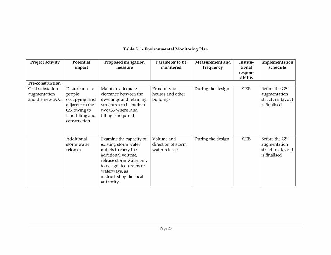
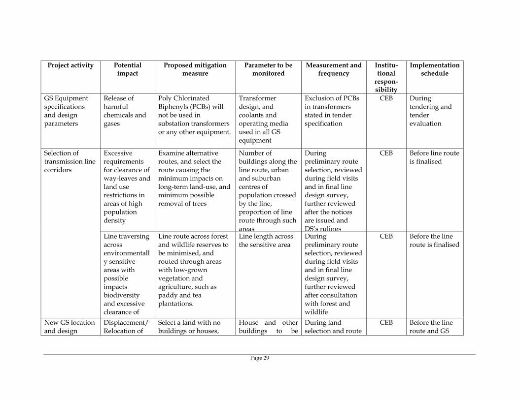
Table 5.1 - Environmental Monitoring Plan
Project activity Potential
impact Proposed mitigation
measure Parameter to be
monitored Measurement and
frequency Institu-tional
respon-sibility
Implementation schedule
Pre-construction Grid substation augmentation and the new SCC
Disturbance to people occupying land adjacent to the GS, owing to land filling and construction
Maintain adequate clearance between the dwellings and retaining structures to be built at two GS where land filling is required
Proximity to houses and other buildings
During the design CEB Before the GS augmentation structural layout is finalised
Additional storm water releases
Examine the capacity of existing storm water outlets to carry the additional volume, release storm water only to designated drains or waterways, as instructed by the local authority
Volume and direction of storm water release
During the design CEB Before the GS augmentation structural layout is finalised
Page 29
Project activity Potential impact
Proposed mitigation measure
Parameter to be monitored
Measurement and frequency
Institu-tional
respon-sibility
Implementation schedule
GS Equipment specifications and design parameters
Release of harmful chemicals and gases
Poly Chlorinated Biphenyls (PCBs) will not be used in substation transformers or any other equipment.
Transformer design, and coolants and operating media used in all GS equipment
Exclusion of PCBs in transformers stated in tender specification
CEB During tendering and tender evaluation
Selection of transmission line corridors
Excessive requirements for clearance of way-leaves and land use restrictions in areas of high population density
Examine alternative routes, and select the route causing the minimum impacts on long-term land-use, and minimum possible removal of trees
Number of buildings along the line route, urban and suburban centres of population crossed by the line, proportion of line route through such areas
During preliminary route selection, reviewed during field visits and in final line design survey, further reviewed after the notices are issued and DS’s rulings
CEB Before line route is finalised
Line traversing across environmentally sensitive areas with possible impacts biodiversity and excessive clearance of
l
Line route across forest and wildlife reserves to be minimised, and routed through areas with low-grown vegetation and agriculture, such as paddy and tea plantations.
Line length across the sensitive area
During preliminary route selection, reviewed during field visits and in final line design survey, further reviewed after consultation with forest and wildlife
CEB Before the line route is finalised
New GS location and design
Displacement/Relocation of
Select a land with no buildings or houses,
House and other buildings to be
During land selection and route
CEB Before the line route and GS

Page 30
Project activity Potential impact
Proposed mitigation measure
Parameter to be monitored
Measurement and frequency
Institu-tional
respon-sibility
Implementation schedule
housing preferably state-owned land
demolished/relocated
selection for each transmission line
location is finalised
New GSS location and augmentation of GSs
Exposure to noise
Design and location of transformers to comply with Sri Lanka noise regulations, noise levels specified in bid docs.
Expected noise emissions based on substation design
During factory tests and after commissioning
CEB Before the GS locations and transformer locations are finalised
Transformers designed with oil spill containment pit, and with emergency oil release and storage system.
Equipment specifications with respect to potential pollutants, and compliance with design specifications
During commissioning tests and compliance checking of civil works
CEB During design of the GSs
Escape of polluting materials
Environmental pollution
GSs to include storm water drainage and sewage disposal systems to avoid surface water pollution.
Substation storm water discharge sewage design
Bid documents to mention detailed specifications, and compliance checking after construction
CEB During design and construction of GSs.
Design of GSs to include fire detection and control systems and firewalls.
Explosions/Fire Hazards to life
Provision of fire fighting equipment to be located close to transformers.
Substation design compliance with fire prevention and control codes in Sri Lanka
Bid document to mention detailed specifications, and compliance checking after construction.
CEB During design and construction of GSs.
Construction
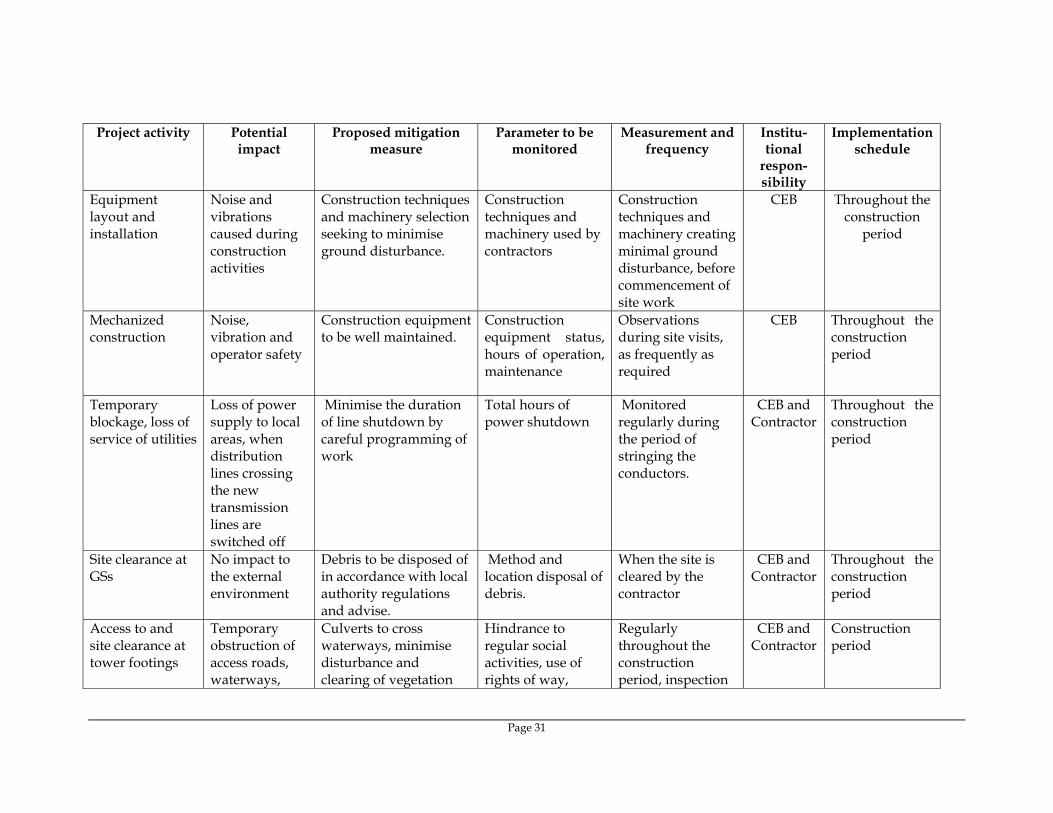
Page 31
Project activity Potential impact
Proposed mitigation measure
Parameter to be monitored
Measurement and frequency
Institu-tional
respon-sibility
Implementation schedule
Equipment layout and installation
Noise and vibrations caused during construction activities
Construction techniques and machinery selection seeking to minimise ground disturbance.
Construction techniques and machinery used by contractors
Construction techniques and machinery creating minimal ground disturbance, before commencement of site work
CEB Throughout the construction
period
Mechanized construction
Noise, vibration and operator safety
Construction equipment to be well maintained.
Construction equipment status, hours of operation, maintenance
Observations during site visits, as frequently as required
CEB Throughout the construction period
Temporary blockage, loss of service of utilities
Loss of power supply to local areas, when distribution lines crossing the new transmission lines are switched off
Minimise the duration of line shutdown by careful programming of work
Total hours of power shutdown
Monitored regularly during the period of stringing the conductors.
CEB and Contractor
Throughout the construction period
Site clearance at GSs
No impact to the external environment
Debris to be disposed of in accordance with local authority regulations and advise.
Method and location disposal of debris.
When the site is cleared by the contractor
CEB and Contractor
Throughout the construction period
Access to and site clearance at tower footings
Temporary obstruction of access roads, waterways,
Culverts to cross waterways, minimise disturbance and clearing of vegetation
Hindrance to regular social activities, use of rights of way,
Regularly throughout the construction period, inspection
CEB and Contractor
Construction period
Page 32
Project activity Potential impact
Proposed mitigation measure
Parameter to be monitored
Measurement and frequency
Institu-tional
respon-sibility
Implementation schedule
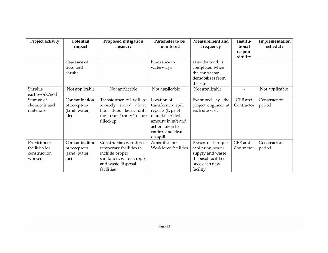
clearance of trees and shrubs
hindrance to waterways
after the work is completed when the contractor demobilises from the site
Surplus earthwork/soil
Not applicable Not applicable Not applicable Not applicable - Not applicable
Storage of chemicals and materials
Contamination of receptors (land, water, air)
Transformer oil will be securely stored above high flood level, until the transformer(s) are filled-up.
Location of transformer; spill reports (type of material spilled, amount in m3) and action taken to control and clean up spill
Examined by the project engineer at each site visit
CEB and Contractor
Construction period
Provision of facilities for construction workers
Contamination of receptors (land, water, air)
Construction workforce temporary facilities to include proper sanitation, water supply and waste disposal facilities.
Amenities for Workforce facilities
Presence of proper sanitation, water supply and waste disposal facilities - once each new facility
CEB and Contractor
Construction period
Page 33
Project activity Potential impact
Proposed mitigation measure
Parameter to be monitored
Measurement and frequency
Institu-tional
respon-sibility
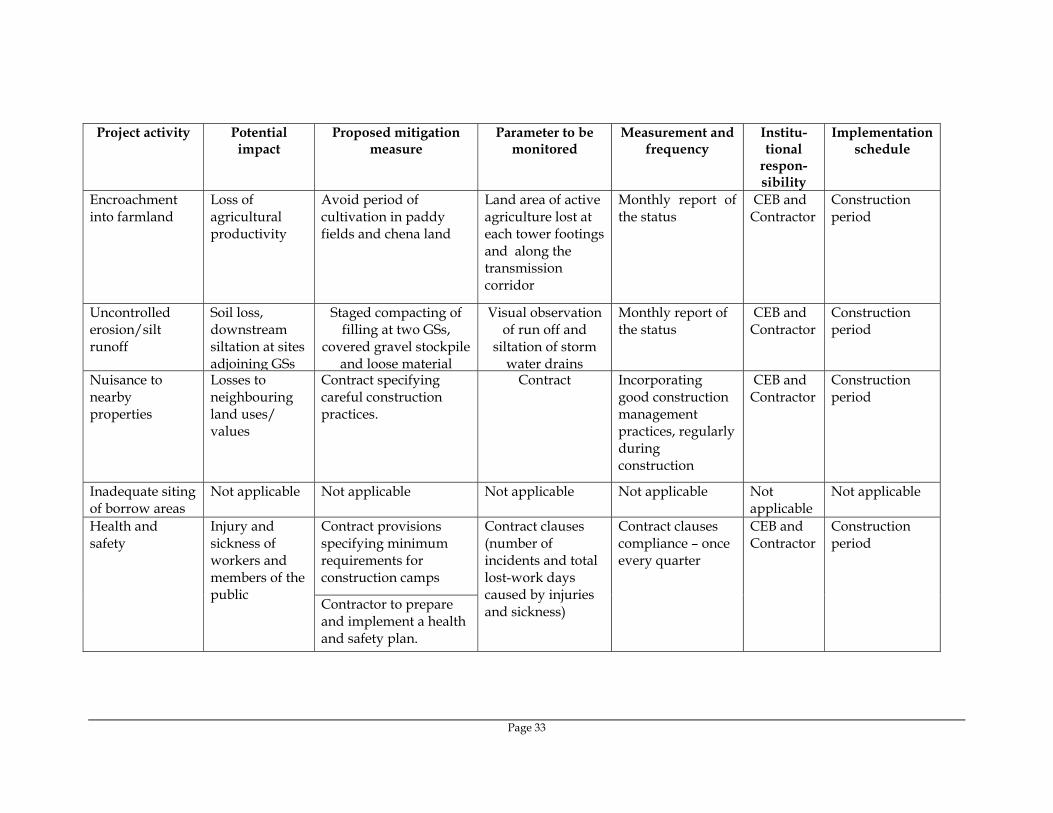
Implementation schedule
Encroachment into farmland
Loss of agricultural productivity
Avoid period of cultivation in paddy fields and chena land
Land area of active agriculture lost at each tower footings and along the transmission corridor
Monthly report of the status
CEB and Contractor
Construction period
Uncontrolled erosion/silt runoff
Soil loss, downstream siltation at sites adjoining GSs
Staged compacting of filling at two GSs,
covered gravel stockpile and loose material
Visual observation of run off and
siltation of storm water drains
Monthly report of the status
CEB and Contractor
Construction period
Nuisance to nearby properties
Losses to neighbouring land uses/ values
Contract specifying careful construction practices.
Contract Incorporating good construction management practices, regularly during construction
CEB and Contractor
Construction period
Inadequate siting of borrow areas
Not applicable Not applicable Not applicable Not applicable Not applicable
Not applicable
Contract provisions specifying minimum requirements for construction camps
Health and safety
Injury and sickness of workers and members of the public
Contractor to prepare and implement a health and safety plan.
Contract clauses (number of incidents and total lost-work days caused by injuries and sickness)
Contract clauses compliance – once every quarter
CEB and Contractor
Construction period

Page 34
Project activity Potential impact
Proposed mitigation measure
Parameter to be monitored
Measurement and frequency
Institu-tional
respon-sibility
Implementation schedule
Contractor to arrange for health and safety training sessions Training of CEB environmental monitoring personnel and project engineers/other staff
Training schedules and training coverage
Number and coverage of programs attended by each person
Implementation of effective environmental monitoring and reporting system using checklist of all contractual environmental requirements
Respective contract checklists and remedial actions taken thereof.
Submission of duly completed checklists of all contracts for each site, once prepared to be used thereafter
Inadequate construction stage monitoring
Likely to increase damages, lost time
Appropriate contact clauses to ensure satisfactory implementation of contractual environmental mitigation measures.
Compliance report related to environmental aspects for the contract
Submission of duly completed compliance report for each contract - once
CEB Construction period
Operation and Maintenance Transformer Oil spillage
Contamination of land/nearby water bodies
Substation transformers located within secure and impervious sump areas with a storage capacity of at least 100%
Transformer oil sump checked through physical measurement of volume and visual
Oil sump volume and permeability, once after completion
CEB During operations
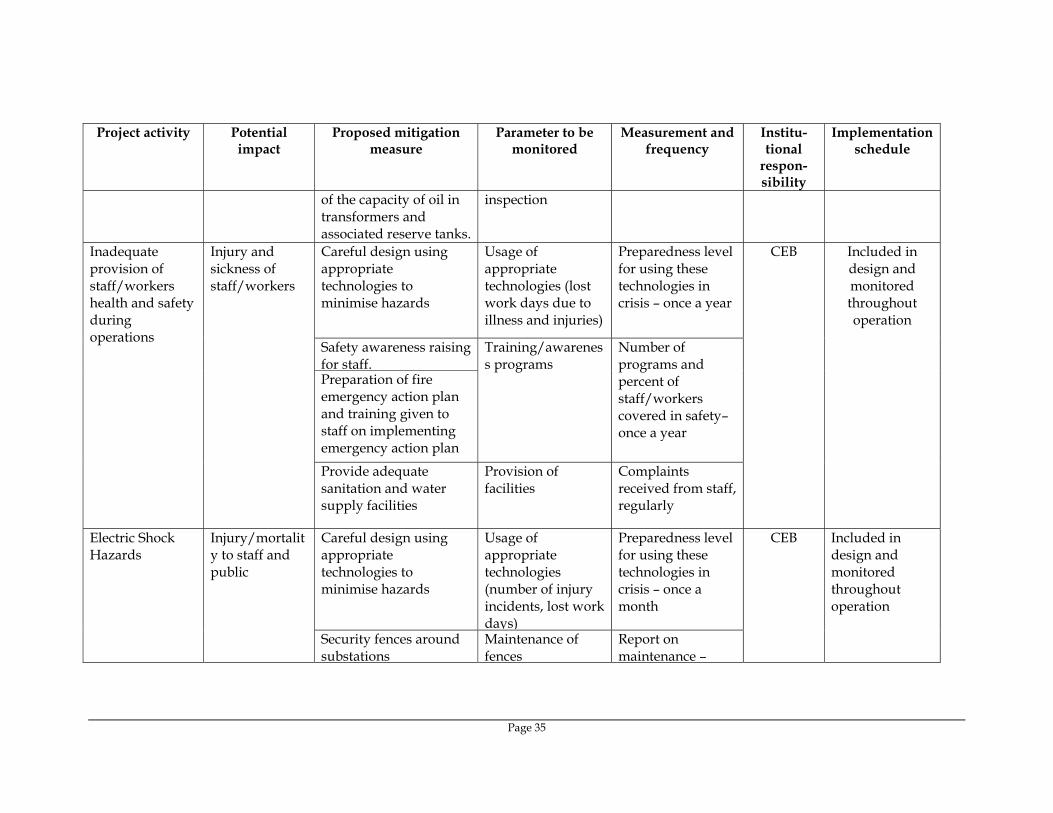
Page 35
Project activity Potential impact
Proposed mitigation measure
Parameter to be monitored
Measurement and frequency
Institu-tional
respon-sibility
Implementation schedule
of the capacity of oil in transformers and associated reserve tanks.
inspection
Careful design using appropriate technologies to minimise hazards
Usage of appropriate technologies (lost work days due to illness and injuries)
Preparedness level for using these technologies in crisis – once a year
Safety awareness raising for staff. Preparation of fire emergency action plan and training given to staff on implementing emergency action plan
Training/awareness programs
Number of programs and percent of staff/workers covered in safety– once a year
Inadequate provision of staff/workers health and safety during operations
Injury and sickness of staff/workers
Provide adequate sanitation and water supply facilities
Provision of facilities
Complaints received from staff, regularly
CEB Included in design and monitored throughout operation
Careful design using appropriate technologies to minimise hazards
Usage of appropriate technologies (number of injury incidents, lost work days)
Preparedness level for using these technologies in crisis – once a month
Electric Shock Hazards
Injury/mortality to staff and public
Security fences around substations
Maintenance of fences
Report on maintenance –
CEB Included in design and monitored throughout operation

Page 36
Project activity Potential impact
Proposed mitigation measure
Parameter to be monitored
Measurement and frequency
Institu-tional
respon-sibility
Implementation schedule
Appropriate warning signs on facilities
Maintenance of warning signs
Electricity safety awareness raising in project areas
Training/awareness programs for all concerned parties
Number of programs and percent of total persons covered – once a year
Adequate training in O&M to all relevant staff of substations maintenance crews.
Operations and maintenance staff skills less than acceptable
Unnecessary environmental losses of various types
Preparation and training in the use of O&M manuals and standard operating
Training/awareness programs for all relevant staff
Number of programs and percent of staff covered – once a year
CEB Throughout operation
Inadequate periodic environmental monitoring.
Diminished ecological and social values.
Staff to receive training in environmental monitoring of project operations and maintenance activities.
Training/awareness programs for all relevant staff
Number of programs and percent of staff covered – once a year
CEB Throughout operation
Noise related Nuisance to neighbouring properties
Substations sited and designed to ensure noise will not be a nuisance.
Noise levels (dB (a))
Noise levels at boundary nearest to properties and consultation with affected parties if any – once a year
CEB Throughout operation

Page 37
6 PUBLIC CONSULTATION AND INFORMATION DISCLOSURE
6.1 Grid Substations Public consultation in case of the augmentation of the existing GSs including the new SCC will be through the application procedure to the Local Authority. The properties are owned by CEB and have presently operational GSs. Once the necessary approvals are obtained from the Local Authority, no specific public consultation is conducted owing to the fact that all new construction and operations are limited to the perimeter of the existing GS. If the members of public require information about the construction work planned or activities related to construction, they will be requested to make a request to CEB if it involves clarifications on the extent of work that is likely to affect the public, especially the owners of lands adjacent to the GS. Any further public consultation, if required, would be arranged and presided by the Divisional Secretary (DS) upon a written request or objection from the public on any aspect related to the project. CEB would be providing the information to the concerned members of public, as directed by the DS.
6.2 Right-of-Way of the Transmission Lines
6.2.1 Preliminary Work Conducted CEB design engineers initially establish several possible alternative routes on a topographical map of the scale 1:50,000. In selecting alternatives, care is taken to avoid areas with significant residential or commercial land-use, and to avoid environmentally sensitive areas such as wildlife sanctuaries and protected areas. The preferred routing any line is always through areas of low-grown agriculture, particularly paddy and tea, and through “chena type” land, where crops are grown in rotation. In the selection of alternative routes selected Habarana-Valachchanai line traverse deviates from the existing corridor, to minimise the traverse through the forest reserve. The width of the corridor for the new 132 kV lines will be 27 meters. A preliminary walk-over survey was conducted for each line, and thereafter, CEB transmission design staff including design engineers examined the ground realities with regard to impacts on land, buildings vegetation, and options available to minimise the impacts. The transmission line corridors are presently at the stage of being finalised with regard to the routing. Environmental approval for the Ukuwela-Pallekelle lines has already been issued.

Page 38
6.2.2 Sri Lanka Environmental Approval Process The first step in the approval process is for Central Environmental Authority (CEA) to appoint a Project Approving Agency (PAA), which is typically a Ministry or a Government Department. A Project Approving Committee (PAC) is established by the PAA, which includes the Divisional Secretaries of all the Divisions traversed by the line, and officials from the relevant state departments and regulatory agencies (such as Department of Forests) and the regional offices of CEA. The DSs will act as the representatives of the public affected by the project. Minutes of PAC meetings are recorded, and circulated to all members of the committee. The PAC in their deliberations, and based on the guidelines provided in the regulations, would specify whether the project would require an Initial Environmental Examination (IEE) or a more comprehensive Environmental Impact Assessment (EIA). Accordingly, a scoping committee is appointed, which may include additional experts in the specific fields of study which the PAC would consider to be important in the context of the project, to prepare the TOR for the IEE/EIA. Then the IEE/EIA is conducted by CEB in accordance with the TOR provided by the scoping committee. In considering the IEE/EIA report for approval, the PAA conducts site visits and stakeholder consultations. Typical participants at these site visits would include the PAA/scoping committee members, the Grama Niladharis (village leaders) of each village traversed by the line, who would represent the public in each village, and the field officers of all the relevant government agencies. Non-governmental agencies and other informal groups such as farmer organisations would also be invited on the recommendation of the officers, as required. During the field visit, all major issues highlighted in previous deliberations and the issues brought to the notice of the PAC during the visit are documented. Minutes are circulated among all the participants. The field visit is immediately followed-up by a site meeting, where certain decisions are made by the PAC with regard to the proposed line. Typical examples are the deviation of a section of the line considering the issues highlighted during the approval process, and relocation of a tower position from a small block of land, which would otherwise make the block of land unusable. Other special situations may include the deviation of a section of the line to avoid a recently-planned housing scheme which was not included in the maps and not noticed during preliminary visits by CEB officials, as construction has not started yet. The PAA and the relevant officers may make more than one field visit either for the same location or different locations along the line route, to adequately cover the issues highlighted in the IEE/EIA and issues directly brought to the notice of the committee by that time. Thereafter, the PAC would either decline approval, or would issues the approval, subject to conditions. In the EIA process, the EIA report is kept open for public comments (announced through newspapers) for a period of one month, and CEB would be required to respond to the written comments from the members of public (which can include comments from NGOs, community-based organisations and institutions, as well) to the satisfaction of the PAC. There is no requirement to open the report for public comments, if the process is IEE.

Page 39
6.2.2.1 Present Status of Environmental Approvals The environmental approval process including public consultations/information disclosure has been completed in July 2006 for the Ukuwela-Pallekelle transmission line, and the minutes of the relevant meetings/discussions and the attendance sheets are attached as Annex 2 & 3 respectively. The Environmental Approval was granted and the transmission line trace (mentioned in this RP) was finalized subsequent to the said public consultation. The environmental approval process for the other transmission lines included in this subproject has already been started. Public consultation / field inspection for proposed Galle – Matara transmission line has been held on 28th and 29th February 2008. The minutes of the meeting / discussion and attendance sheet is attached as Annex 4 & 5 respectively. A summary of the main issues discussed and agreed are given below.
• Soil excavated from the pits for the tower foundations in paddy fields should be removed away in order to avoid adverse effects to the top soil.
• Proposed line route crosses the southern highway in more than three places and adequate clearance has to be provided to the highway with the consultation of the Road Development Authority.
• Proposed line route passes through Kirelakelle area for a short distance (where the existing Matara grid substation is already located), which may be declared as a protected area in future by Dept. of Wildlife Conservation. Views of Department of Wildlife Conservation has to be obtained in construction of the line.
Although a number of issues raised by the stakeholders/DSs/Grama Niladaris etc., has been discussed and agreed upon by CEB(as highlighted in the minutes), no changes to the selected line route was proposed. Public consultation / field inspection for proposed Habarana – Valachchanai transmission line has been held on 24th March 2008. The minutes of the meeting / discussion and attendance sheet is attached as Annex 6 & 7 respectively. A summary of the main issues discussed and agreed are given below.
• Divisional Secretary – Welikanda and GN – Manampitiya suggested to deviate a section of the line in order to avoid it passing through the Welikanda town. A deviation to relevant section, avoiding Welikanda town is suggested by CEB, to which all the participants have agreed. The line route with the proposed deviation is shown in Annex 8.
• It was revealed that the proposed line traverse parallel to the existing HT line, which is closer to the runaway of Hingurkgoda Air strip belonging to the Air Force. CEB officers explained that although new line it is parallel to the existing line, it will be further away to the Air Port than the existing line. However, it has been agreed that the Air Force should be informed and the necessary steps should be taken to get their approval by the CEB, as there may be a proposal to expand the airstrip.
• It was revealed that proposed line crosses the railway line in three locations and the officers from Railway Department has to be consulted in the construction of line. A permanent cradle guard/mesh will be installed by CEB under the transmission line at each point it crosses the railway.
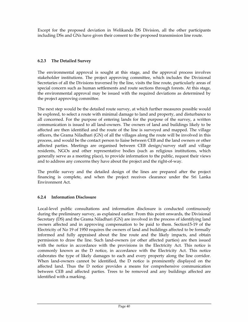
Page 40
Except for the proposed deviation in Welikanda DS Division, all the other participants including DSs and GNs have given their consent to the proposed transmission line route.
6.2.3 The Detailed Survey The environmental approval is sought at this stage, and the approval process involves stakeholder institutions. The project approving committee, which includes the Divisional Secretaries of all the Divisions traversed by the line, visits the line route, particularly areas of special concern such as human settlements and route sections through forests. At this stage, the environmental approval may be issued with the required deviations as determined by the project approving committee. The next step would be the detailed route survey, at which further measures possible would be explored, to select a route with minimal damage to land and property, and disturbance to all concerned. For the purpose of entering lands for the purpose of the survey, a written communication is issued to all land-owners. The owners of land and buildings likely to be affected are then identified and the route of the line is surveyed and mapped. The village officers, the Grama Niladhari (GN) of all the villages along the route will be involved in this process, and would be the contact person to liaise between CEB and the land owners or other affected parties. Meetings are organised between CEB design/survey staff and village residents, NGOs and other representative bodies (such as religious institutions, which generally serve as a meeting place), to provide information to the public, request their views and to address any concerns they have about the project and the right-of-way. The profile survey and the detailed design of the lines are prepared after the project financing is complete, and when the project receives clearance under the Sri Lanka Environment Act.
6.2.4 Information Disclosure Local-level public consultations and information disclosure is conducted continuously during the preliminary survey, as explained earlier. From this point onwards, the Divisional Secretary (DS) and the Grama Niladhari (GN) are involved in the process of identifying land owners affected and in approving compensation to be paid to them. Section15-19 of the Electricity of No 19 of 1950 requires the owners of land and buildings affected to be formally informed and fully appraised about the line route and the likely impacts, and obtain permission to draw the line. Such land-owners (or other affected parties) are then issued with the notice in accordance with the provisions in the Electricity Act. This notice is commonly known as the D notice, in accordance with the Electricity Act. This notice elaborates the type of likely damages to each and every property along the line corridor. When land-owners cannot be identified, the D notice is prominently displayed on the affected land. Thus the D notice provides a means for comprehensive communication between CEB and affected parties. Trees to be removed and any buildings affected are identified with a marking.

Page 41
6.2.5 Public Consultation and Appeal Procedure Affected persons receiving a D notice may submit written submissions within 14 days from the date of the D notice. These objections are received by the Divisional Secretary (DS), who would then hold an inquiry within two weeks upon expiry of the 30-day period allowed in the D notice, in the presence of the affected party (or parties) and CEB officials. The affected parties and CEB are provided an opportunity to explain their position on the issues, and in most cases, an amicable settlement is reached through this formal consultation process. The DS would be the final authority to give a ruling on an issue either to proceed with the activities or prohibiting activities, if no amicable settlement can be reached. Such rulings may be challenged in a court of law. The DS determines the compensation to be awarded, and approves the sums to be paid for trees and buildings affected. More details of this compensation package would be provided in the Resettlement and Compensation Plan to be submitted to ADB in addition to this IEE. The felling of trees will be the responsibility of the owner and any timber would remain the property of the owner, in spite of the compensation that would have been awarded.
6.3 Procedure to Handle Public Complaints During Implementation Phase CEB accords the highest priority to establish a mechanism for accommodating public complaints and comments, both from the affected parties and others, throughout the project implementation period. The first level of contact for members of public or the affected parties would be the project engineers. All representations will be received by the project engineers, and communicated to the DS if the issue warrants intervention or inquiry by Government officials. If the issue requires issuing instructions to the contractors, these will be communicated to the contractors. In general, most public interactions would be on construction-related issues, which are temporary but nevertheless require attention, such as the impacts on minor access roads when heavy equipment or gravel is transported regularly. In case of the transmission line, issues related to tower locations and clearance of tress will continue to be referred to CEB from time to time, which will be resolved through consultation with the affected parties. Temporary obstruction of roadways during stringing of conductors, are typical concerns raised by the public. If any matter that cannot be resolved by the project engineer, it will be referred to the project manager in charge of the sub-project, and if required, will be referred to the Project Director. During project implementation, in case of complaints, CEB would issue written instructions to the contractor(s) in items related to the environmental management plan, requesting compliance. CEB field staff will ensure the contractors and his staff would comply with the instructions, in all work connected with the project, within the project site(s) as well as outside the immediate project siting areas.

Page 42
7 FINDINGS AND RECOMMENDATIONS This IEE study is conducted at the preliminary stage of the National Grid Development Project, proposed to be implemented from year 2008 onwards. The study reveals that the environmental impacts of the project elements during construction and operation can be divided into two distinct categories, namely,
(a) Thirteen Grid Substations (GSs) to be augmented, the new System Control Centre to be built within an existing GSS and four new GSs to be built.
(b) Establishment of new rights-of-way for four 132 kV transmission lines and the construction of lines
7.1 Environmental Impacts of the new SCC, GS Augmentation and New GSs As the SCC and all the GSs are to be augmented within the existing space available, no significant environmental impacts are expected in these projects. Land filling is required at two of the GSs to be augmented, which requires to be managed carefully, so that adjoining lands and houses will not be affected. In the other grid substations, no land preparation is required. Access to all the GSs is available through public highways, and in two locations only, a local public road has to be used to reach the existing GS. Thus no new roadways would be required in the GS augmentations. Similarly, no relocation of assets owned by members of the public would be required, while at two GSs, buildings owned by CEB would have to be relocated. Standard practices would be adopted in the design of the GS to ensure transformer oil spills in an emergency would be fully contained within the containment pit immediately beneath the power transformers. CEB adopts international standards on transformer noise limits, which will be tested during type tests conducted in the factory. CEB will continue to implement and enhance the present safety practices in construction and operation of substations.
7.2 Transmission Lines For the transmission lines, there will be no involuntary relocation of any sort, and the houses below the line can remain and agricultural activities up to a height of 3 m can continue. The most significant impact of the line would be the clearance of trees and other way-leaves permanently, which will be compensated on the basis of their life-long value of lost production.
8 CONCLUSIONS The proposed subproject is a Power Transmission Project of Category B, in the classification under ADB environmental guidelines. There will be no involuntary relocation of private or public buildings, except modifications to CEB’s own buildings within a few grid substations. The main environmental impacts would be the loss of vegetation along the 21 km new line corridor, which has been minimised by selecting the longest possible segment of the route to traverse paddy fields. Careful management of the project construction activities and subsequent management of the assets would make the proposed project to be environmentally acceptable and comparable with any other transmission project.


![CEYLON ELECTRICITY BOARD REGION [1] … · How to contact your service provider 5 3 ... A Region of the Ceylon Electricity Board operates under the ... Northern Province](https://img.pdfslide.net/doc/110x75/5b15e66b7f8b9a961e8be7d7/ceylon-electricity-board-region-1-how-to-contact-your-service-provider-5-3.jpg)


![Sensitivity Analysis - Indico [Home]indico.ictp.it/event/a13196/session/4/contribution/19/material/0/0.pdf · Sensitivity Analysis Thushara De Silva Ceylon Electricity Board, Sri](https://img.pdfslide.net/doc/110x75/5d5184f188c99378448bd5d0/sensitivity-analysis-indico-home-sensitivity-analysis-thushara-de-silva.jpg)


