Embed Size (px)
Citation preview
CF 20/35 CF 35/50
Open Flue Gas Fired Boiler
THIS APPLIANCE IS FOR USE WITH NATURAL GAS ONLY.
Installation and Servicing Instructions
LEAVE THESE INSTRUCTIONS ADJACENT TO THE GAS METER.
Page 1
Page 2
FLAMINGO CF 20/35 G.C. No. 41 .605.59
35/50 G.C. No. 41 .605.60
IMPORTANT
This appliance must be installed by a competent person as stated in the Gas Safety (Installation and Use) Regulations 1984.
Flamingo boilers are certified by BSI for safety. It is therefore important that no external devices (e.g., flue dampers, economisers etc.) be directly connected to theseappliances unless covered by these installation instructions or otherwise recommended in writing.
Any direct connection of a control device not approved by Potterton could invalidate the BSI certificate and the normal warranty.
LIST OF CONTENTS
Page No .
General 3
Accessories 3
Installation Data 3
Boiler Dimensions 4
Site Requirements 6
Technical Data 7
Installation Instructions 12
Commissioning 16
Servicing Instructions 19
Control Systems, Pipework and Wiring Guide Supplied in
User’s Instructions Literature Pack
Page 2
GENERAL - Page 3
Potterton Flamingo Open Flue boilers are automatically controlled, wall-mounted appliances, using a cast iron heat exchanger and are available in two outputs ranging from5.86-14.65 kW (20,000-50,000 Btu/h). Refer to TECHNICAL DATA page 8. The boilers which are designed to provide domestic hot water and/or central heating must beused on INDIRECT hot water systems only. The cast iron heat exchangers are suitable f

or use on sealed or open vented gravity hot water/pumped central heating systems orfully pumped systems.
ACCESSORIES
The following range of Potterton system controls are also available and further information will be provided upon request.
Electronic Programmer EP. 2000, E.P. 3000, E.P. 4000. Programmable Electronic Thermostat PET 1 Thermostatic Radiator Valve PV456 and PH456 Electronic Cylinder Thermostat PTT 1 Electronic Room Thermostat PRT 1 Spring Return Zone Valve PMV2 Spring Return Diverter Valve PMV3
INSTALLATION DATA
The installation of the boiler must be in accordance with the latest relevant requirements of the Gas Safety (Installation and Use) Regulations 1984, local building regulations,current lEE Wiring Regulations and the bye-laws of the local Water Undertaking.
Detailed recommendations are contained in the following British Standards and Codes of Practice.
BS. 6798 1987, BS. 5440 Part 1 1978 BS. 5440 Part 2 1976, BS. 5449 Part 1 1977 BS. 5546 1979, BS. 4814 1979, BS. 6891 BUILDING REGULATIONS MODEL WATER BYE-LAWS BRITISH GAS PUBLICATION DM2 GAS SAFETY (INSTALLATION AND USE) REGULATIONS 1984 BUILDING STANDARDS (SCOTLAND) REGULATIONS.
Page 3
INSTALLATION DATA - Page 4
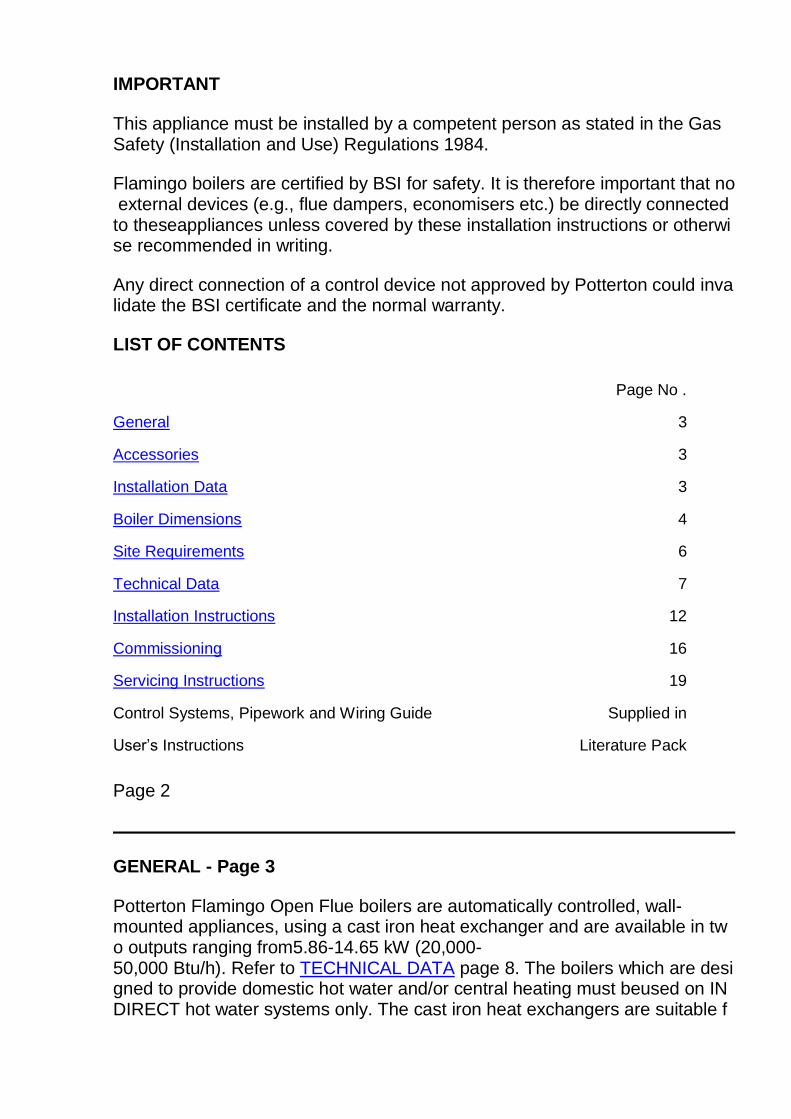
FIG. 1. BOILER DIMENSIONS (mm)
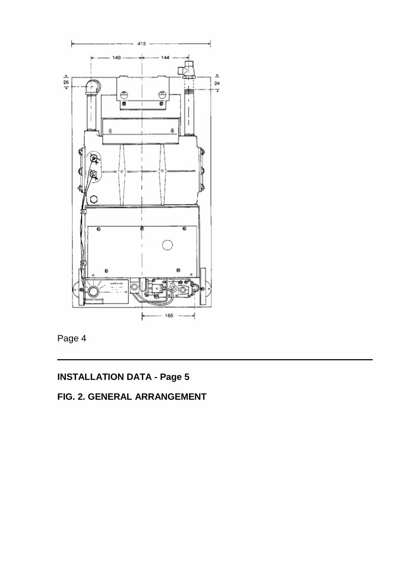
Page 4
INSTALLATION DATA - Page 5
FIG. 2. GENERAL ARRANGEMENT
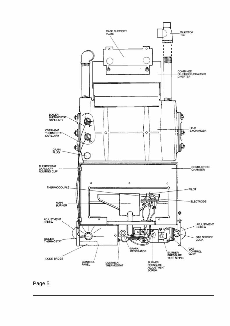
Page 5
SITE REQUIREMENTS - Page 6
These boilers are not suitable for external installation.
This appliance must not be installed in bathrooms, shower rooms, bedrooms, bed-sitting rooms, garages or rooms where highly inflammable materials or vapours are likelyto be present. Fitting in toilets or cloakrooms is not recommended but it is permitted, provided the ventilation and combustion air is taken direct from outside.
Where the installation of the boiler will be in an unusual location special procedures may be necessary and BS. 6798 1987 gives detailed guidance on this aspect.
Ensure that the gas supply pipe and meter are large enough for this appliance and any others that may be run off the same meter. Reference should be made to BS. 6891.
Boiler Mounting Surface
The boiler must be mounted on a flat wall, which may be of combustible material and must be sufficiently robust to take the weight of the boiler. The requirements of the localauthorities and the Building Regulations must be adhered to.
IMPORTANT NOTICE: TIMBER FRAMED HOUSES
If the appliance is to be fitted in a timber framed building it should be fitted in accordance with British Gas Publication. ‘Guide for Gas Installations in Timber Framed Housing’. If in doubt, advice must be sought from the local Gas Region of British Gas.
Clearances Around The Boiler
The following minimum clearances must be maintained after installation for correct operation and servicing of the boiler-
610 mm (2 ft) at the front of the boiler:- 5 mm (0.2 in) each side of the boiler 100 mm (4 in) at the top (measured from the top of boiler case) 100 mm (4 in) at the bottom of boiler
Additional clearances may be required to lift the boiler on to the wall.
COMBUSTION AIR AND VENTILATION REQUIREMENTS
General recommendations are given in BS. 5440 Part 2, and the following notes are given as a general guide.
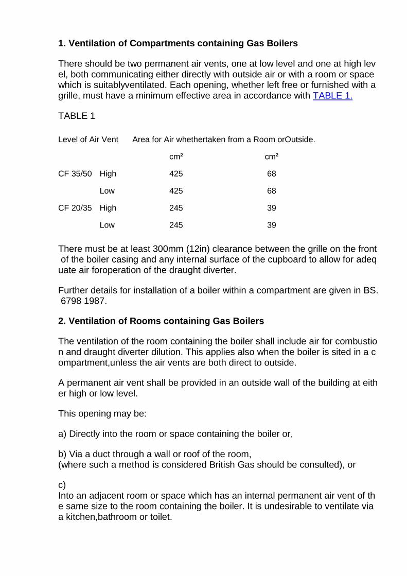
1. Ventilation of Compartments containing Gas Boilers
There should be two permanent air vents, one at low level and one at high level, both communicating either directly with outside air or with a room or space which is suitablyventilated. Each opening, whether left free or furnished with a grille, must have a minimum effective area in accordance with TABLE 1.
TABLE 1
Level of Air Vent Area for Air whethertaken from a Room orOutside.
cm² cm²
CF 35/50 High 425 68
Low 425 68
CF 20/35 High 245 39
Low 245 39
There must be at least 300mm (12in) clearance between the grille on the front of the boiler casing and any internal surface of the cupboard to allow for adequate air foroperation of the draught diverter.
Further details for installation of a boiler within a compartment are given in BS. 6798 1987.
2. Ventilation of Rooms containing Gas Boilers
The ventilation of the room containing the boiler shall include air for combustion and draught diverter dilution. This applies also when the boiler is sited in a compartment,unless the air vents are both direct to outside.
A permanent air vent shall be provided in an outside wall of the building at either high or low level.
This opening may be:
a) Directly into the room or space containing the boiler or,
b) Via a duct through a wall or roof of the room, (where such a method is considered British Gas should be consulted), or
c) Into an adjacent room or space which has an internal permanent air vent of the same size to the room containing the boiler. It is undesirable to ventilate via a kitchen,bathroom or toilet.
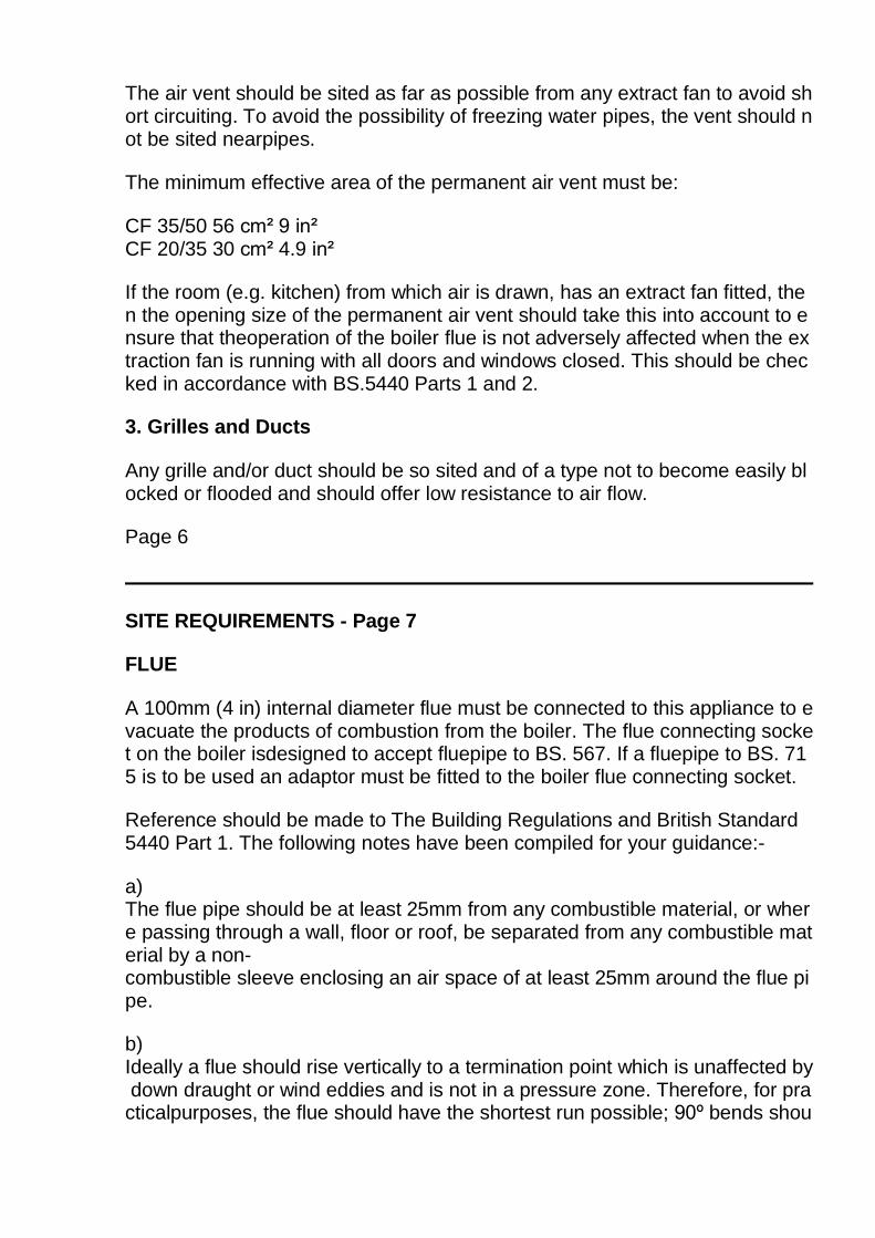
The air vent should be sited as far as possible from any extract fan to avoid short circuiting. To avoid the possibility of freezing water pipes, the vent should not be sited nearpipes.
The minimum effective area of the permanent air vent must be:
CF 35/50 56 cm² 9 in² CF 20/35 30 cm² 4.9 in²
If the room (e.g. kitchen) from which air is drawn, has an extract fan fitted, then the opening size of the permanent air vent should take this into account to ensure that theoperation of the boiler flue is not adversely affected when the extraction fan is running with all doors and windows closed. This should be checked in accordance with BS.5440 Parts 1 and 2.
3. Grilles and Ducts
Any grille and/or duct should be so sited and of a type not to become easily blocked or flooded and should offer low resistance to air flow.
Page 6
SITE REQUIREMENTS - Page 7
FLUE
A 100mm (4 in) internal diameter flue must be connected to this appliance to evacuate the products of combustion from the boiler. The flue connecting socket on the boiler isdesigned to accept fluepipe to BS. 567. If a fluepipe to BS. 715 is to be used an adaptor must be fitted to the boiler flue connecting socket.
Reference should be made to The Building Regulations and British Standard 5440 Part 1. The following notes have been compiled for your guidance:-
a) The flue pipe should be at least 25mm from any combustible material, or where passing through a wall, floor or roof, be separated from any combustible material by a non-combustible sleeve enclosing an air space of at least 25mm around the flue pipe.
b) Ideally a flue should rise vertically to a termination point which is unaffected by down draught or wind eddies and is not in a pressure zone. Therefore, for practicalpurposes, the flue should have the shortest run possible; 90º bends shou

ld be avoided. The terminal must be at least above roof edge level and must be of a type acceptableto British Gas.
c) Whever possible there should be at least 2 ft (600mm) of vertical flue from the boiler flue socket.
NOTE: A split socket should be fitted in this length.
d) Horizontal runs should be avoided. If a near horizontal length is unavoidable, it must be followed by at least twice that length of vertical flue.
e) Wherever possible internal stacks, lined if necessary, should be used.
f) All brick chimneys must be lined with a liner acceptable to British Gas.
g) Where condensation is likely a means of draining must be provided.
h) If an existing flue is being used, ensure that it has been thoroughly swept before lining or connecting the boiler.
ELECTRICITY SUPPLY
A 240V ~ 50 Hz., single phase electricity supply fused at 3A must be provided in accordance with the latest edition of the I.E.E. wiring regulations and any other localregulations that may apply. The current rating of the wiring to the boiler must exceed 3 amperes and have a cross sectional area of at least 0.75 mm² in accordance with BS.6500 1984 Table 16. The method of connection to the electricity supply MUST facilitate complete isolation of the appliance, preferably by the use of a fused three-pin plugand unswitched, shuttered socket outlet, both complying with the requirements of BS. 1363.
Alternatively, connection may be made via a fused double-pole isolator having a contact separation of at least 3 mm in all poles and serving the appliance and systemcontrols only.
TECHNICAL DATA
Maximum working head - 30.5m (100 ft)
Minimum Working Head (Fully Pumped systems) - 305mm (1 ft)
Minimum Circulating Head (Gravity systems) - 1.2m(4ft)
Gas supply pressure - 20 mbar
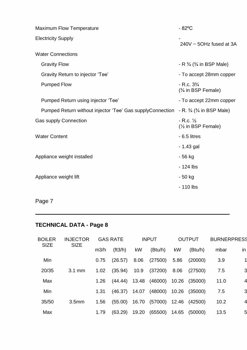
Maximum Flow Temperature - 82ºC
Electricity Supply - 240V ~ 5OHz fused at 3A
Water Connections
Gravity Flow - R ¾ (¾ in BSP Male)
Gravity Return to injector ‘Tee’ - To accept 28mm copper
Pumped Flow - R.c. 3¾ (¾ in BSP Female)
Pumped Return using injector ‘Tee’ - To accept 22mm copper
Pumped Return without injector ‘Tee’ Gas supplyConnection - R. ¾ (¾ in BSP Male)
Gas supply Connection - R.c. ½ (½ in BSP Female)
Water Content - 6.5 litres
- 1.43 gal
Appliance weight installed - 56 kg
- 124 lbs
Appliance weight lift - 50 kg
- 110 lbs
Page 7
TECHNICAL DATA - Page 8
BOILER SIZE
INJECTOR SIZE
GAS RATE INPUT OUTPUT BURNERPRESSURE
m3/h (ft3/h) kW (Btu/h) kW (Btu/h) mbar in wg
Min
3.1 mm
0.75 (26.57) 8.06 (27500) 5.86 (20000) 3.9 1.6
20/35 1.02 (35.94) 10.9 (37200) 8.06 (27500) 7.5 3.0
Max 1.26 (44.44) 13.48 (46000) 10.26 (35000) 11.0 4.4
Min
3.5mm
1.31 (46.37) 14.07 (48000) 10.26 (35000) 7.5 3.0
35/50 1.56 (55.00) 16.70 (57000) 12.46 (42500) 10.2 4.1
Max 1.79 (63.29) 19.20 (65500) 14.65 (50000) 13.5 5.4
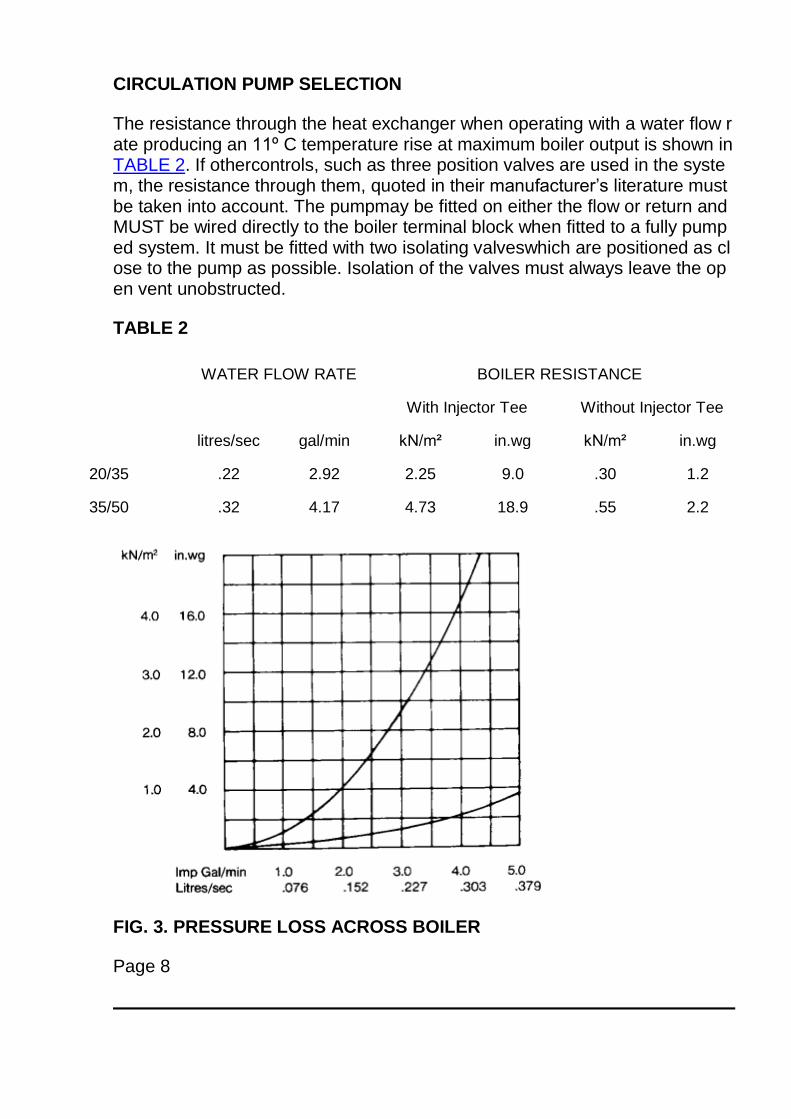
CIRCULATION PUMP SELECTION
The resistance through the heat exchanger when operating with a water flow rate producing an 11º C temperature rise at maximum boiler output is shown in TABLE 2. If othercontrols, such as three position valves are used in the system, the resistance through them, quoted in their manufacturer’s literature must be taken into account. The pumpmay be fitted on either the flow or return and MUST be wired directly to the boiler terminal block when fitted to a fully pumped system. It must be fitted with two isolating valveswhich are positioned as close to the pump as possible. Isolation of the valves must always leave the open vent unobstructed.
TABLE 2
WATER FLOW RATE BOILER RESISTANCE
With Injector Tee Without Injector Tee
litres/sec gal/min kN/m² in.wg kN/m² in.wg
20/35 .22 2.92 2.25 9.0 .30 1.2
35/50 .32 4.17 4.73 18.9 .55 2.2
FIG. 3. PRESSURE LOSS ACROSS BOILER
Page 8
TECHNICAL DATA - Page 9
THE SYSTEM
The boiler must be used on Indirect hot water systems only. It is suitable for use on sealed or open vented gravity domestic hot water/pumped central heating systems or fullypumped systems.
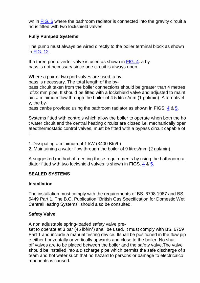
The system should be designed so that the maximum static head does not exceed 30.5m (100 ft) and a minimum on fully pumped systems of 305mm (1 ft.). See FIG. 4.
If a minimum 305 mm (1 ft) head is used extra care should be taken when designing the system to ensure that pumping over or sucking down at the vent pipe cannot occur.
Gravity domestic hot water circuits should have a minimum circulating head of 1.2 m (4 ft). SEE FIG. 6. To prevent reverse circulation in the gravity circuit when the pump isrunning, an injector tee is provided. This must be installed as shown in FIG 10a.
To prevent nuisance operation of the overheat thermostat, it is important that where electrically operated zone valves are used the boiler is wired so that it does not cyclewhen the zone valves are closed. Also systems fitted with controls that close both hot water and central heating circuits while the boiler is still hot must be fitted with a by-passcircuit to dissipate the residual heat within the boiler.
Further information on by-pass arrangements is provided in later notes and illustrations.
Drain-off taps should be fitted in the pipework close to the boiler if it is in a low point of the system.
Note:
Although the system can be emptied using the drain-off taps installed in the pipework around the system, to empty the boiler it is necessary to remove the drain-off plug in thefront lower left of the casting. SEE FIG. 2.
Combined Gravity Hot Water and Pumped Central Heating systems.
Where a cylinder thermostat and zone valve are fitted to control the temperature of the domestic hot water it is recommended that a by-pass be installed in the gravity circuit.A suggested method of doing this is sho
wn in FIG. 6 where the bathroom radiator is connected into the gravity circuit and is fitted with two lockshield valves.
Fully Pumped Systems
The pump must always be wired directly to the boiler terminal block as shown in FIG. 12.
If a three port diverter valve is used as shown in FIG. 4. a by-pass is not necessary since one circuit is always open.
Where a pair of two port valves are used, a by-pass is necessary. The total length of the by-pass circuit taken from the boiler connections should be greater than 4 metres of22 mm pipe. It should be fitted with a lockshield valve and adjusted to maintain a minimum flow through the boiler of 4.5 litres/mm (1 gal/min). Alternatively, the by-pass canbe provided using the bathroom radiator as shown in FIGS. 4 & 5.
Systems fitted with controls which allow the boiler to operate when both the hot water circuit and the central heating circuits are closed i.e. mechanically operatedthermostatic control valves, must be fitted with a bypass circuit capable of:-
1 Dissipating a minimum of 1 kW (3400 Btu/h). 2. Maintaining a water flow through the boiler of 9 litres/mm (2 gal/min).
A suggested method of meeting these requirements by using the bathroom radiator fitted with two lockshield valves is shown in FIGS. 4 & 5.
SEALED SYSTEMS
Installation
The installation must comply with the requirements of BS. 6798 1987 and BS. 5449 Part 1. The B.G. Publication "British Gas Specification for Domestic Wet CentralHeating Systems" should also be consulted.
Safety Valve
A non adjustable spring-loaded safety valve pre-set to operate at 3 bar (45 lbf/in²) shall be used. It must comply with BS. 6759 Part 1 and include a manual testing device. Itshall be positioned in the flow pipe either horizontally or vertically upwards and close to the boiler. No shut-off valves are to be placed between the boiler and the safety valve.The valve should be installed into a discharge pipe which permits the safe discharge of steam and hot water such that no hazard to persons or damage to electricalcomponents is caused.
Pressure Gauge
A pressure gauge incorporating a fill pressure indicator, covering the range 0-4 bar (60 lbf/in²) shall be fitted to the system. It should be connected to the system, preferably atthe same point as the expansion vessel. Its location should be visible from the filling point.
Expansion Vessel
A diaphragm type vessel to BS. 4814 Part 1 shall be fitted close to the inlet side of the pump. The connecting pipework should not be less than 15 mm (½ in nominal).Pipework connecting the expansion vessel should not incorporate valves of any sort. Methods of supporting the vessel are supplied by the manufacturer. The nitrogen or aircharge pressure of the expansion vessel shall not be less than the hydrostatic head, (height of the top point of the system above the expansion vessel). To size the expansionvessel it is first necessary to calculate the volume of water in the system in litres. The following volumes may be used as a conservative guide to calculating the systemvolume.
Boiler Heat Exchanger 6.5 litres
Small Bore Pipework 1 litre per kW of system output
Micro Bore Pipework 7 litres output
Steel Panel Radiators 8 litres per kW of systemoutput
Low Water CapacityRadiators 2 litres per kW of systemoutput
Hot Water Cylinder 2 litres
If the system is extended the expansion vessel volume may have to be increased unless previous provision has been made for the extension. Where a vessel of thecalculated size is not available, the next available larger size should be used.
Page 9
TECHNICAL DATA - Page 10
The boiler flow temperature is controlled at approximately 82˚C. The vessel size can now be determined from the following table where V = system volume in litres.
Vessel Charge Pressure (bar) 0.5 1.0
Initial System Pressure (bar) 1.0 1.0
Expansion Vessel Volume (litres)
V X 0.11 V X 0.087
Cylinder
The hot water cylinder must be an indirect coil type or a direct cylinder fitted with an immersion calorifier suitable for operating at a gauge pressure of 0.3 bar (5 lbf/in²) inexcess of safety valve setting. Single feed indirect cylinders are not suitable for sealed systems.
Method of Make-Up
Provision shall be made for replacing water loss from the system either:
i) from a make-up vessel or tank mounted in a position higher than the top point of the system, and connected through a non-return valve either to the system on the returnside of hot water cylinder or the return side of all heat emitters.
or
ii) where access to a make-up vessel would be difficult, by using the mains top up method or a remote automatic pressurisation and make up unit as illustrated in FIG. 5METHODS 1 and 2.
Mains Connection
There shall be no connection to the mains water supply or to the water storage tank which supplies domestic water even through a non-return valve, without the approval ofthe local Water Authority.
Filling Point
The system shall be fitted with a filling point at low level which incorporates a stop valve to BS. 1010 and a double check valve (approved by the National Water Council) tobe fitted in this order from the system mains. Refer to FIG. 5 METHOD 1.
FIG. 4 OPEN VENTED FULLY PUMPED SYSTEM FITTED WITH A COMBINED FEED AND VENT
Page 10
TECHNICAL DATA - Page 11
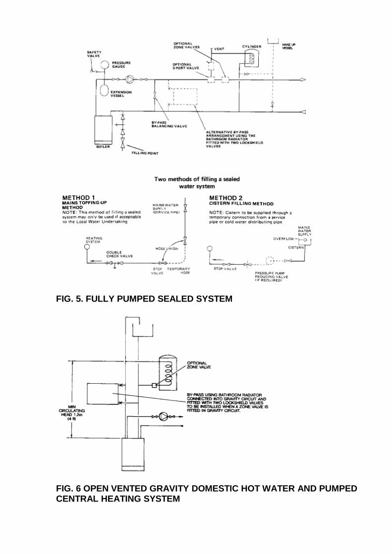
FIG. 5. FULLY PUMPED SEALED SYSTEM
FIG. 6 OPEN VENTED GRAVITY DOMESTIC HOT WATER AND PUMPED CENTRAL HEATING SYSTEM
Page 11
INSTALLATION INSTRUCTIONS - Page 12
The boiler and its associated equipment will arrive on site in two cardboard cartons. The contents of each carton is as follows:
CARTON 1 CARTON 2
Boiler Literature Pack containing:
Case Support Plate Installation and Servicing Instructions
Boiler Mounting Bracket User’s Instructions
Polythene Bag containing: Control Systems Pipework and WiringGuide
Injector Tee Template
Adjustment Screws -2 off Accessory Packs
Gas Service Cock Boiler Casing
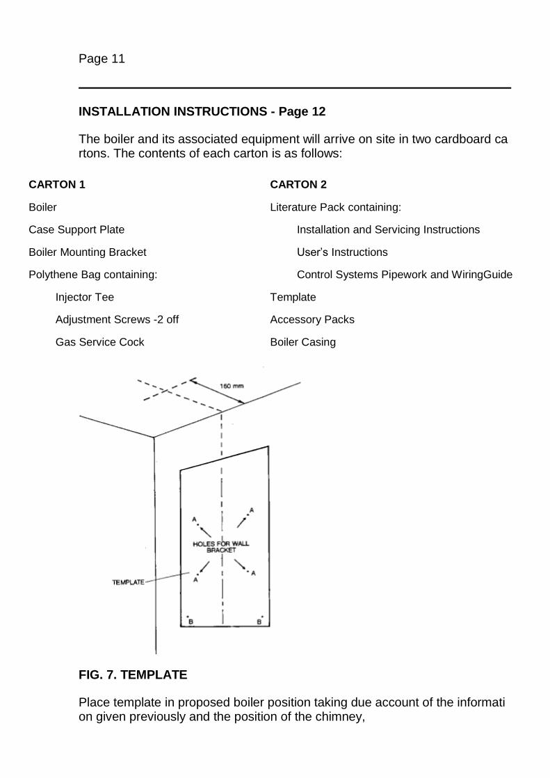
FIG. 7. TEMPLATE
Place template in proposed boiler position taking due account of the information given previously and the position of the chimney,
(the minimum side clearances areautomatically allowed for). Refer to page 6 for top and bottom clearances which can be measured from the template.
Ensure that the template is level and mark hole positions ‘A’. ‘B’, and centre of boiler reference line through the slot in the bottom edge of the template.
If the flue is to rise through the ceiling, mark out centre line of hole for flue by extending the dotted line on template vertically and measure out 160mm from rear wall asillustrated.
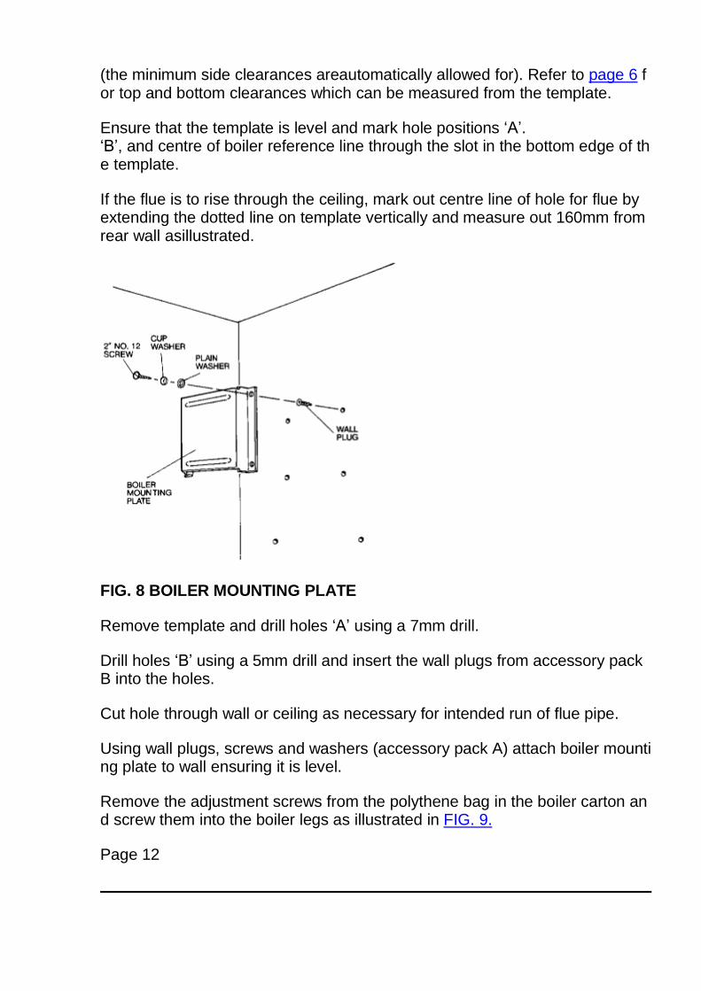
FIG. 8 BOILER MOUNTING PLATE
Remove template and drill holes ‘A’ using a 7mm drill.
Drill holes ‘B’ using a 5mm drill and insert the wall plugs from accessory pack B into the holes.
Cut hole through wall or ceiling as necessary for intended run of flue pipe.
Using wall plugs, screws and washers (accessory pack A) attach boiler mounting plate to wall ensuring it is level.
Remove the adjustment screws from the polythene bag in the boiler carton and screw them into the boiler legs as illustrated in FIG. 9.
Page 12
INSTALLATION INSTRUCTIONS - Page 13
LIFTING THE BOILER
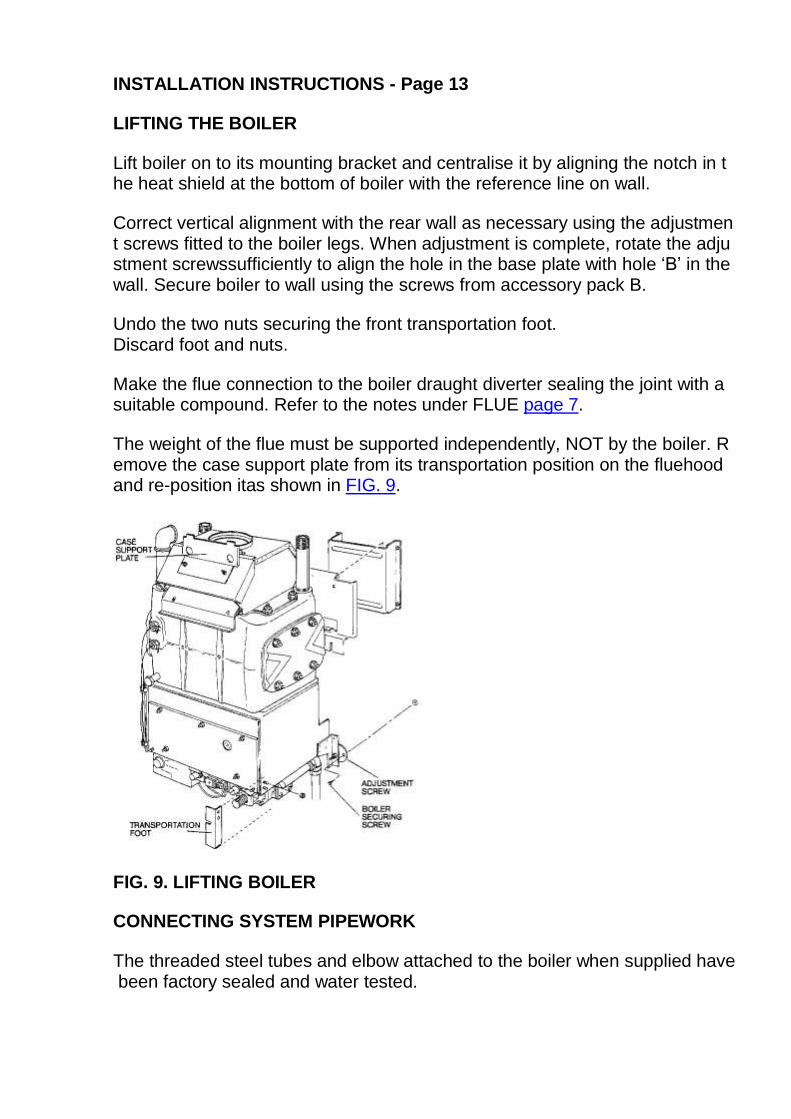
Lift boiler on to its mounting bracket and centralise it by aligning the notch in the heat shield at the bottom of boiler with the reference line on wall.
Correct vertical alignment with the rear wall as necessary using the adjustment screws fitted to the boiler legs. When adjustment is complete, rotate the adjustment screwssufficiently to align the hole in the base plate with hole ‘B’ in the wall. Secure boiler to wall using the screws from accessory pack B.
Undo the two nuts securing the front transportation foot. Discard foot and nuts.
Make the flue connection to the boiler draught diverter sealing the joint with a suitable compound. Refer to the notes under FLUE page 7.
The weight of the flue must be supported independently, NOT by the boiler. Remove the case support plate from its transportation position on the fluehood and re-position itas shown in FIG. 9.
FIG. 9. LIFTING BOILER
CONNECTING SYSTEM PIPEWORK
The threaded steel tubes and elbow attached to the boiler when supplied have been factory sealed and water tested.
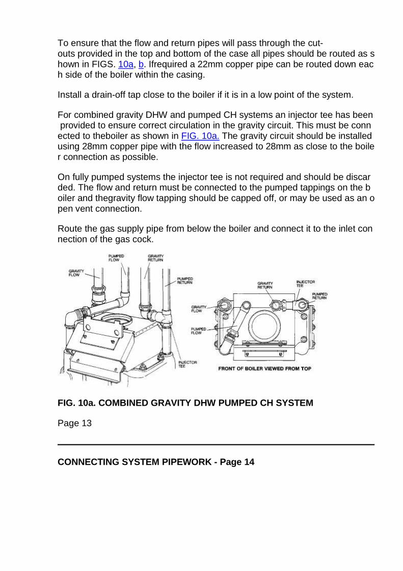
To ensure that the flow and return pipes will pass through the cut-outs provided in the top and bottom of the case all pipes should be routed as shown in FIGS. 10a, b. Ifrequired a 22mm copper pipe can be routed down each side of the boiler within the casing.
Install a drain-off tap close to the boiler if it is in a low point of the system.
For combined gravity DHW and pumped CH systems an injector tee has been provided to ensure correct circulation in the gravity circuit. This must be connected to theboiler as shown in FIG. 10a. The gravity circuit should be installed using 28mm copper pipe with the flow increased to 28mm as close to the boiler connection as possible.
On fully pumped systems the injector tee is not required and should be discarded. The flow and return must be connected to the pumped tappings on the boiler and thegravity flow tapping should be capped off, or may be used as an open vent connection.
Route the gas supply pipe from below the boiler and connect it to the inlet connection of the gas cock.
FIG. 10a. COMBINED GRAVITY DHW PUMPED CH SYSTEM
Page 13
CONNECTING SYSTEM PIPEWORK - Page 14
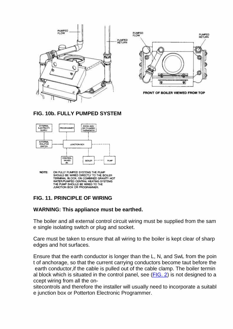
FIG. 10b. FULLY PUMPED SYSTEM
FIG. 11. PRINCIPLE OF WIRING
WARNING: This appliance must be earthed.
The boiler and all external control circuit wiring must be supplied from the same single isolating switch or plug and socket.
Care must be taken to ensure that all wiring to the boiler is kept clear of sharp edges and hot surfaces.
Ensure that the earth conductor is longer than the L, N, and SwL from the point of anchorage, so that the current carrying conductors become taut before the earth conductor,if the cable is pulled out of the cable clamp. The boiler terminal block which is situated in the control panel, see (FIG. 2) is not designed to accept wiring from all the on-sitecontrols and therefore the installer will usually need to incorporate a suitable junction box or Potterton Electronic Programmer.
The principle of wiring is shown in FIG. 11. It should be noted that the pump must be wired directly to the boiler terminal block on FULLY PUMPED systems and to thejunction box or programmer on combined GRAVITY HOT WATER/PUMPED CENTRAL HEATING systems.
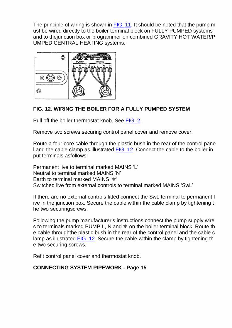
FIG. 12. WIRING THE BOILER FOR A FULLY PUMPED SYSTEM
Pull off the boiler thermostat knob. See FIG. 2.
Remove two screws securing control panel cover and remove cover.
Route a four core cable through the plastic bush in the rear of the control panel and the cable clamp as illustrated FIG. 12. Connect the cable to the boiler input terminals asfollows:
Permanent live to terminal marked MAINS ‘L’ Neutral to terminal marked MAINS ‘N’ Earth to terminal marked MAINS ‘ ’ Switched live from external controls to terminal marked MAINS ‘SwL’
If there are no external controls fitted connect the SwL terminal to permanent live in the junction box. Secure the cable within the cable clamp by tightening the two securingscrews.
Following the pump manufacturer’s instructions connect the pump supply wires to terminals marked PUMP L, N and on the boiler terminal block. Route the cable throughthe plastic bush in the rear of the control panel and the cable clamp as illustrated FIG. 12. Secure the cable within the clamp by tightening the two securing screws.
Refit control panel cover and thermostat knob.
CONNECTING SYSTEM PIPEWORK - Page 15
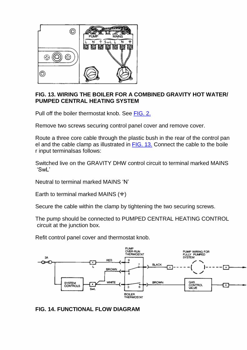
FIG. 13. WIRING THE BOILER FOR A COMBINED GRAVITY HOT WATER/PUMPED CENTRAL HEATING SYSTEM
Pull off the boiler thermostat knob. See FIG. 2.
Remove two screws securing control panel cover and remove cover.
Route a three core cable through the plastic bush in the rear of the control panel and the cable clamp as illustrated in FIG. 13. Connect the cable to the boiler input terminalsas follows:
Switched live on the GRAVITY DHW control circuit to terminal marked MAINS ‘SwL’
Neutral to terminal marked MAINS ‘N’
Earth to terminal marked MAINS ( )
Secure the cable within the clamp by tightening the two securing screws.
The pump should be connected to PUMPED CENTRAL HEATING CONTROL circuit at the junction box.
Refit control panel cover and thermostat knob.
FIG. 14. FUNCTIONAL FLOW DIAGRAM
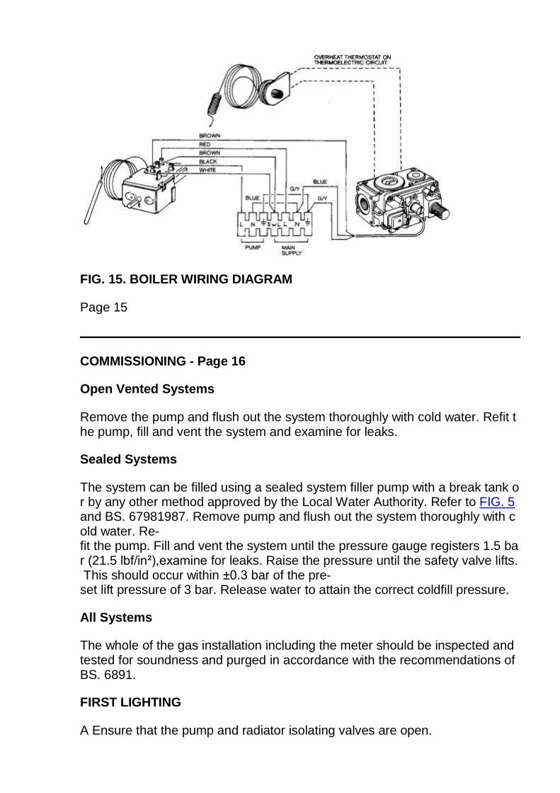
FIG. 15. BOILER WIRING DIAGRAM
Page 15
COMMISSIONING - Page 16
Open Vented Systems
Remove the pump and flush out the system thoroughly with cold water. Refit the pump, fill and vent the system and examine for leaks.
Sealed Systems
The system can be filled using a sealed system filler pump with a break tank or by any other method approved by the Local Water Authority. Refer to FIG. 5 and BS. 67981987. Remove pump and flush out the system thoroughly with cold water. Re-fit the pump. Fill and vent the system until the pressure gauge registers 1.5 bar (21.5 lbf/in²),examine for leaks. Raise the pressure until the safety valve lifts. This should occur within ±0.3 bar of the pre-set lift pressure of 3 bar. Release water to attain the correct coldfill pressure.
All Systems
The whole of the gas installation including the meter should be inspected and tested for soundness and purged in accordance with the recommendations of BS. 6891.
FIRST LIGHTING
A Ensure that the pump and radiator isolating valves are open.
B Turn the boiler thermostat to the ‘O’ position.
C Turn on the main gas supply and the gas service cock on boiler.
D Ensure that the time control, if fitted is in an ‘ON’ condition, and that the room and/or cylinder thermostats, where fitted are set to high temperatures.
E Switch on the external electricity Supply to the boiler. In the event of an electrical fault after installation of the appliance, preliminary electrical system checks must be carriedout as described in the BG multimeter instruction book. The checks to be carried out are: A - Earth Continuity, B - Short Circuit, C - Polarity, D - Resistance to Earth.
F Partly depress and turn the gas control knob clock-wise ensuring the symbol lines up with the datum mark on the gas valve body. See FIG. 16. This ensures that the valveis in the ‘OFF’ condition.
G Partly depress and turn the control knob anti-clockwise until the symbol lines up with the datum mark on the gas valve body. Press and hold in the control knob and pressthe spark generator button until a click is heard. Release the spark generator button and repeat operation until the pilot ignites. See FIGS. 2 and 16
Hold in the control knob for a further 15 seconds. On release the pilot should remain alight.
Partly depress and turn the control knob anti-clockwise until the symbol lines up with the datum mark on the gas valve body.
NOTE:
On first lighting, establishment of the pilot flame may be slightly delayed due to the presence of air in the pipework. If the pilot fails to light or goes out at any time, immediatelyturn the control knob clockwise as far as possible, then release it and wait three minutes before repeating the lighting procedure. The control knob should not be touchedduring this period.
H Turn the boiler thermostat on and to a high setting and the main burner will light.
I Set the boiler thermostat and the room and/or cylinder thermostat(s) and time control, where fitted, to their required operating conditions.
J After the boiler has operated for five minutes check that there is no spillage or leakage of combustion products in accordance with BS 5440 Part 1.
Check soundness of all appliance gas carrying components and joints using leak detection fluid and a mirror where necessary.
K Switch off the boiler, using the thermostat knob.
FINAL ADJUSTMENT
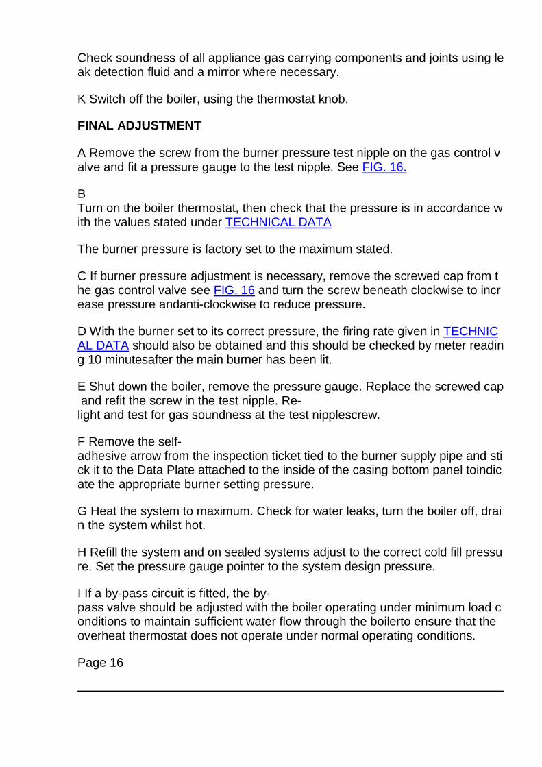
A Remove the screw from the burner pressure test nipple on the gas control valve and fit a pressure gauge to the test nipple. See FIG. 16.
B Turn on the boiler thermostat, then check that the pressure is in accordance with the values stated under TECHNICAL DATA
The burner pressure is factory set to the maximum stated.
C If burner pressure adjustment is necessary, remove the screwed cap from the gas control valve see FIG. 16 and turn the screw beneath clockwise to increase pressure andanti-clockwise to reduce pressure.
D With the burner set to its correct pressure, the firing rate given in TECHNICAL DATA should also be obtained and this should be checked by meter reading 10 minutesafter the main burner has been lit.
E Shut down the boiler, remove the pressure gauge. Replace the screwed cap and refit the screw in the test nipple. Re-light and test for gas soundness at the test nipplescrew.
F Remove the self-adhesive arrow from the inspection ticket tied to the burner supply pipe and stick it to the Data Plate attached to the inside of the casing bottom panel toindicate the appropriate burner setting pressure.
G Heat the system to maximum. Check for water leaks, turn the boiler off, drain the system whilst hot.
H Refill the system and on sealed systems adjust to the correct cold fill pressure. Set the pressure gauge pointer to the system design pressure.
I If a by-pass circuit is fitted, the by-pass valve should be adjusted with the boiler operating under minimum load conditions to maintain sufficient water flow through the boilerto ensure that the overheat thermostat does not operate under normal operating conditions.
Page 16
COMMISSIONING - Page 17
FIG. 16. GAS CONTROL VALVE
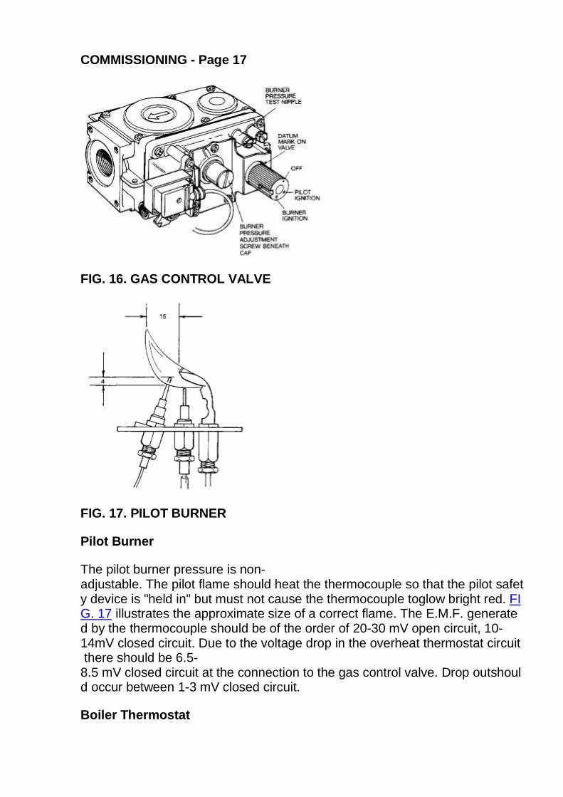
FIG. 17. PILOT BURNER
Pilot Burner
The pilot burner pressure is non-adjustable. The pilot flame should heat the thermocouple so that the pilot safety device is "held in" but must not cause the thermocouple toglow bright red. FIG. 17 illustrates the approximate size of a correct flame. The E.M.F. generated by the thermocouple should be of the order of 20-30 mV open circuit, 10-14mV closed circuit. Due to the voltage drop in the overheat thermostat circuit there should be 6.5-8.5 mV closed circuit at the connection to the gas control valve. Drop outshould occur between 1-3 mV closed circuit.
Boiler Thermostat
At its minimum and maximum settings, the thermostat should control the water flow temperature at approximately 55ºC-82ºC (130º F- 180º F). The thermostat has beencalibrated by the makers and no attempt should be made to re-calibrate it on site. Turn the thermostat to the ‘O’ position and check that the main burner shuts down.
Pump Over-run Thermostat (Applicable on fully pumped systems only)
The over-run thermostat will keep the pump running when the boiler has shut down, as long as the water temperature within the boiler is above approximately 79ºC (174ºF). Adrop of approximately 11ºC (20ºF) will occur before the thermostat will switch off the pump.
Overheat Thermostat
The overheat thermostat is pre-set and no adjustment is possible. It will require manually re-setting and the pilot re-lighting if an overheat condition occurs. The re-set buttoncan be found on the right hand side of the control panel. See FIG. 2.
Gas Control Valve
1) Main Solenoid
Check the operation of the valve by turning off the electricity supply, either by the isolating switch or time control, where installed. The main burner must shut downimmediately.
2) Flame Failure Valve
Turn the gas control knob to the ‘off’ position. The pilot must shut down, and a "click" indicating thermocouple drop out, should be heard within 60 seconds.
External Controls
Check that any other external controls connected in the system such as time clocks and thermostats, control the boiler as required.
Ensure that the electrical supply to the boiler is switched ‘off’.
Fitting Boiler Case
Fit the boiler case by engaging the holes in the case top panel over the lugs on the support plate which is attached to the fluehood. See FIG. 18.
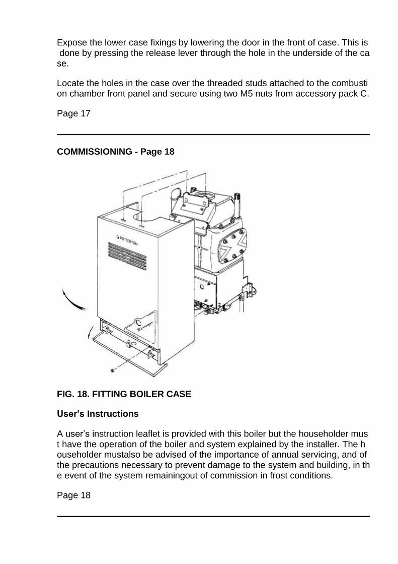
Expose the lower case fixings by lowering the door in the front of case. This is done by pressing the release lever through the hole in the underside of the case.
Locate the holes in the case over the threaded studs attached to the combustion chamber front panel and secure using two M5 nuts from accessory pack C.
Page 17
COMMISSIONING - Page 18
FIG. 18. FITTING BOILER CASE
User’s Instructions
A user’s instruction leaflet is provided with this boiler but the householder must have the operation of the boiler and system explained by the installer. The householder mustalso be advised of the importance of annual servicing, and of the precautions necessary to prevent damage to the system and building, in the event of the system remainingout of commission in frost conditions.
Page 18
SERVICING INSTRUCTIONS - Page 19
To ensure continued safe and efficient operation of the boiler, it is necessary to carry out servicing and cleaning at regular intervals. The frequency of cleaning will dependupon the particular installation conditions, and the use to which the boiler is put, but in general, once per year should be adequate.
Servicing is best arranged by a contract placed with Potterton International Limited and further details are available from the local Potterton Regional Service Office.
The boiler DATA PLATE and WIRING DIAGRAM are attached to the inside of the casing bottom panel. The boiler CODE NUMBER which should be quoted when orderingspares or requesting information is on the front of the control panel below the boiler thermostat knob.
The following notes apply to the boiler and its controls but it should be remembered that attention must also be paid to the heating circuit itself including radiator valves,thermostats, the time control and the expansion and feed water system. It is advisable to clean the boiler immediately after the end of the heating season.
In all cases prior to servicing, light up the boiler and check that the pilot and main burners have a clean, even flame and that the gas rate and main burner pressure is correctlyset.
Before the start of any servicing work, switch off at the external electricity supply by disconnecting the plug at the socket or switching off external isolating switch. Turn off thegas service cock.
NOTE:
After completing any servicing or replacement of components check for gas soundness and carry out functional checks.
1. PREPARING THE BOILER FOR SERVICING
A Expose the lower case securing nuts by lowering the door in the front of casing. Remove the two securing nuts. See FIG. 18. Remove case by lifting it from the locating lugsat the top of the boiler.
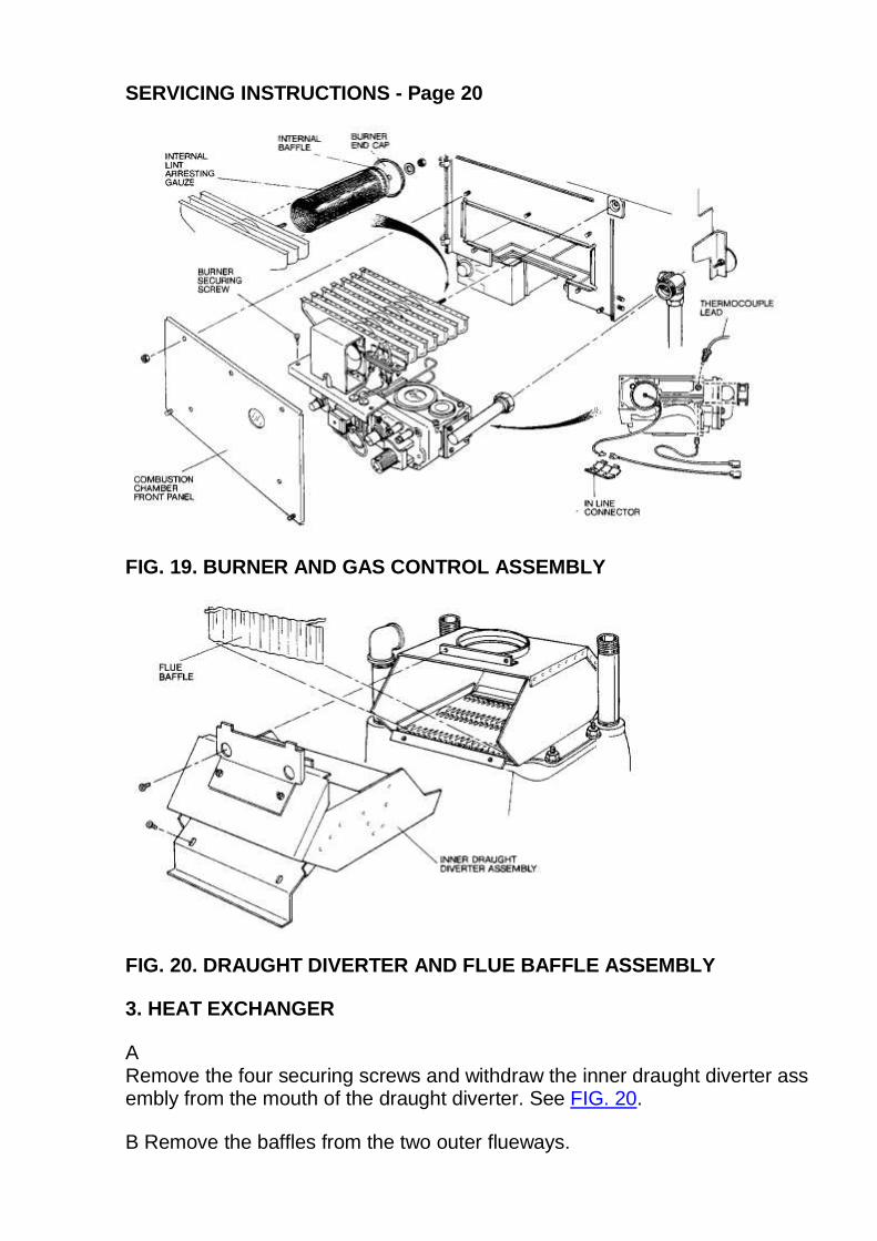
B Remove the 5 nuts securing the combustion chamber front panel and remove panel. See FIG. 19. Inspect the rope seal on the front panel and replace if damaged.
2. MAIN BURNER ASSEMBLY - REMOVAL AND CLEANING
Refer to FIG. 19 and carry out the following:
A Undo the union of the gas service cock outlet.
B Disconnect the two blue wires from the overheat thermostat. Release the wires from rear of control panel by sliding the retaining grommet from slotted hole.
C Unplug the electrical lead from the gas valve.
D Remove the two main burner securing screws, lift out the main burner and gas control assembly.
E Unscrew the M5 nut on CF 35/50 or hexagonal locating peg on CF 20/35 which secure the burner end cap. Remove burner end cap. Withdraw the internal baffle and gauzefrom within the burner. See FIG. 19. Thoroughly clean the gauze using a brush or vacuum cleaner.
F. Clean all deposits from the surface of the burner flame strip with a soft brush or vacuum cleaner and ensure there is no fluff in the entry of the burner venturi.
G. Remove the main burner injector and ensure the orifice is clean.
H. PILOT BURNER
The following operations are only necessary if the pilot flame is distorted or the wrong size. See FIG. 17.
Remove the pilot assembly from the burner by unscrewing the two pilot mounting screws and nuts, disconnect the electrode lead from electrode, uncouple the thermocoupleand pilot gas tube nuts at the base of the pilot assembly. Flex pilot assembly forward to clear bracket, and withdraw assembly upwards. The pilot injector sits loosely on top ofthe pilot tube, or may be retained in the pilot head itself. Remove and inspect the pilot injector for dirt deposits and clean if necessary. Likewise inspect and clean theelectrode and thermocouple using a soft brush.
I. Re-assemble the injector, pilot, gauze, internal baffle and end cap to the burner but do not re-fit the main burner assembly to the boiler at this stage as the flueways in theheat exchanger have first to be cleaned.
Page 19
SERVICING INSTRUCTIONS - Page 20
FIG. 19. BURNER AND GAS CONTROL ASSEMBLY
FIG. 20. DRAUGHT DIVERTER AND FLUE BAFFLE ASSEMBLY
3. HEAT EXCHANGER
A Remove the four securing screws and withdraw the inner draught diverter assembly from the mouth of the draught diverter. See FIG. 20.
B Remove the baffles from the two outer flueways.
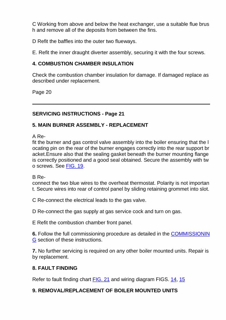
C Working from above and below the heat exchanger, use a suitable flue brush and remove all of the deposits from between the fins.
D Refit the baffles into the outer two flueways.
E. Refit the inner draught diverter assembly, securing it with the four screws.
4. COMBUSTION CHAMBER INSULATION
Check the combustion chamber insulation for damage. If damaged replace as described under replacement.
Page 20
SERVICING INSTRUCTIONS - Page 21
5. MAIN BURNER ASSEMBLY - REPLACEMENT
A Re-fit the burner and gas control valve assembly into the boiler ensuring that the locating pin on the rear of the burner engages correctly into the rear support bracket.Ensure also that the sealing gasket beneath the burner mounting flange is correctly positioned and a good seal obtained. Secure the assembly with two screws. See FIG. 19.
B Re-connect the two blue wires to the overheat thermostat. Polarity is not important. Secure wires into rear of control panel by sliding retaining grommet into slot.
C Re-connect the electrical leads to the gas valve.
D Re-connect the gas supply at gas service cock and turn on gas.
E Refit the combustion chamber front panel.
6. Follow the full commissioning procedure as detailed in the COMMISSIONING section of these instructions.
7. No further servicing is required on any other boiler mounted units. Repair is by replacement.
8. FAULT FINDING
Refer to fault finding chart FIG. 21 and wiring diagram FIGS. 14, 15
9. REMOVAL/REPLACEMENT OF BOILER MOUNTED UNITS
MAIN BURNER
Refer to FIG. 19 and carry out the following:
a) Switch off the external electricity supply by disconnecting the plug at the socket or switching off external isolating switch.
b) Carry out operations A and B as described in section 1 PREPARING THE BOILER FOR SERVICING.
c Turn off the gas service cock and remove burner and gas control assembly as described in section 2. MAIN BURNER ASSEMBLY - REMOVAL AND CLEANING,operations A, B, C, D, G. Separate the pilot from the main burner as described in the same section, operation H.
d) Remove split grommets sealing the thermocouple lead, pilot tube and electrode lead to the burner mounting flange.
e) Remove the four screws securing the burner manifold flange to the gas control valve. Note: A spacer is used at this joint requiring the use of two sealing gaskets.
f) Lift burner away from the gas control valve while feeding the thermocouple lead, electrode lead and pilot tube through the holes in the burner mounting flange.
g) Remove the rear locking nut securing the spark generator to the mounting bracket on the burner and withdraw the spark generator.
h Replacement is the reverse of removal. Use new sealing gaskets on reassembly. Ensure that the thermocouple lead, electrode lead and pilot tube are correctly replaced inthe split grommets. Ensure also that the sealing gasket beneath the burner mounting flange is correctly positioned and a good seal is obtained.
i) Follow the full commissioning procedure as detailed in the COMMISSIONING section of these instructions.
LINT ARRESTING GAUZE
To remove the lint arresting gauze follow the procedures described in section 1 PREPARING THE BOILER FOR SERVICING and section 2 MAIN BURNER ASSEMBLY -REMOVAL and CLEANING operations A, B, C, D, E.
Replacement is the reverse of removal.
GAS CONTROL VALVE
This operation is most easily carried out by first removing the burner and gas control valve assembly as follows:-
a) Switch off the external electricity supply by disconnecting the plug at the socket or switching off external isolating switch.
b) Remove boiler case and combustion chamber front panel as described in 1 PREPARING THE BOILER FOR SERVICING operations A and B.
c) Turn off the gas service cock and remove main burner assembly as described in 2. MAIN BURNER ASSEMBLY - REMOVAL AND CLEANING, operations A, B, C, D.
d) Disconnect the pilot supply tube at the gas valve.
e) Disconnect the thermocouple from the interrupter at the rear of the gas control valve.
f) Slide the blue wire with its plastic insulating boot from the thermocouple connection point at the rear of the gas control. Disconnect the black thermocouple interrupter wirefrom the blue overheat thermostat wire at in-line connector.
g) Remove the four screws securing the burner manifold flange to the flange on the gas control valve outlet pipe. Note: A spacer is used at this joint requiring the use of twosealing gaskets.
h) Remove the four screws securing the inlet pipe to the gas control valve. Replacement is the reverse of removal. Use new sealing gaskets on reassembly. Do notovertighten the rear thermocouple connection.
i) Follow the full commissioning procedure as detailed in the COMMISSIONING section of these instructions.
Page 21
SERVICING INSTRUCTIONS - Page 22
PILOT ASSEMBLY and INJECTOR
Refer to section in SERVICING INSTRUCTIONS.
PILOT FILTER
The pilot burner is protected from blockage by a pilot filter situated within the gas control valve. The filter is large and designed to last the life of the gas control valve undernormal operating conditions. It is therefore unlikely to need replacing. However in the event of pilot filter blockage being suspected the complete control valve will need to bereplaced.
THERMOCOUPLE
a ) Switch off the external electricity supply by disconnecting the plug at the socket or switching off external isolating switch.
b) Remove boiler case and combustion chamber front panel as described in 1 PREPARING THE BOILER FOR SERVICING (operations A and B).
c) Disconnect the thermocouple lead from the gas control valve and pilot. Withdraw thermocouple lead through grommet in burner mounting flange, noting the route the leadtakes so that the replacement can be routed in a similar manner to eliminate sharp bends.
d) Replacement is the reverse of removal. Ensure that the thermocouple capillary is correctly replaced in the split grommet.
Do not overtighten the thermocouple nut.
ELECTRODE
a) Switch off the external electricity supply by disconnecting the plug at the socket or switching off external isolating switch.
b ) Remove boiler case and combustion chamber front panel as described in 1 PREPARING THE BOILER FOR SERVICING (operations A and B).
c) Pull off the electrode lead from electrode.
d) Unscrew the nut securing the electrode to the pilot and withdraw the electrode.
e) Replacement is the reverse of removal.
COMBUSTION CHAMBER INSULATION
a) Switch off the external electricity supply by disconnecting the plug at the socket or switching off the external isolating switch.
b) Remove boiler case and combustion chamber front panel as described in section 1 PREPARING THE BOILER FOR SERVICING operations A and B.
c) Remove the burner assembly as described in section 2. MAIN BURNER ASSEMBLY - REMOVAL AND CLEANING operations A, B, C, D.
d) To remove the insulation from the front, rear and door, bend back the retaining tabs and lift out.
To replace the side insulation it is necessary to first remove the front and rear insulation as previously described. Then remove the clips securing heat reflector plates to thelocating studs on the base of the combustion chamber and lift out reflector plates. Bend back retaining tabs and lift out insulation.
e) Replacement is the reverse of removal.
f) Follow the full commissioning procedure as detailed in the COMMISSIONING section of these instructions.
PILOT VIEWING WINDOW
a) Switch off the external electricity supply by disconnecting the plug at the socket or switching off external isolating switch.
b) Remove boiler case and combustion chamber front panel as described in 1 PREPARING THE BOILER FOR SERVICING (operations A and B).
c) Release the viewing window retaining frame by straightening the tabs which pass through the combustion chamber front panel. Remove the frame and lift out the glass.Take care not to damage the sealing gaskets when dismantling.
d) Replacement is the reverse of removal.
ELECTRODE LEAD
a) Switch off the external electricity supply by disconnecting the plug at the socket or switching off external isolating switch.
b) Remove boiler case and combustion chamber front panel as described in 1 PREPARING THE BOILER FOR SERVICING (operations A and B.)
c) Pull off electrode lead from spark generator and electrode. Remove the split grommet and withdraw the electrode lead through the hole in burner mounting flange.
d) Replacement is the reverse of removal. Ensure that the end of the electrode lead covered with black sleeving is att ached to the spark generator and that the lead iscorrectly replaced in the split grommet.
SPARK GENERATOR
a) Switch off the external electricity supply by disconnecting the plug at the socket or switching off external isolating switch.
b) Remove boiler case as described in section 1 PREPARING THE BOILER FOR SERVICING operation A.
c Pull off electrode lead from spark generator, remove rear locking nut securing spark generator to its mounting bracket and withdraw spark generator.
d) Replacement is the reverse of removal.
Page 22
SERVICING INSTRUCTIONS - Page 23
BOILER THERMOSTAT
a) Switch off the external electricity supply by disconnecting the plug at the socket or switching off external isolating switch.
b) Remove boiler case as described in section 1 PREPARING THE BOILER FOR SERVICING operation A.
c) Pull off the thermostat knob and remove the two screws securing the control panel cover and remove cover. Remove the two screws securing the thermostat to the controlpanel.
d) Disconnect the electrical connections as follows:- White from terminal No.3, Brown from 6, Black from 7, Brown from 8, Red from 9.
e) Remove the split pin retaining the thermostat bulb and withdraw bulb from its pocket. Remove capillary from its routing clips. See FIG. 2
f) Replacement is the reverse of removal. The bulb of the new thermostat should be coated in heat conducting paste.
OVERHEAT THERMOSTAT
a) Switch off the external electricity supply by disconnecting the plug at the socket or switching off external isolating switch.
b) Remove boiler case as described in section 1 PREPARING THE BOILER FOR SERVICING operation A.
c) Remove locking nut securing thermostat to control panel.
d) Disconnect the two blue wires from the thermostat terminals.
f) Remove the split pin retaining the thermostat bulb and withdraw the bulb with its spacer from the pocket. Remove capillary from its routing clips. See FIG. 2.
g) Replacement is the reverse of removal. Ensure that the spacer is correctly positioned to retain the thermostat bulb in the bottom of pocket.
Page 23
SERVICING INSTRUCTIONS - Page 24
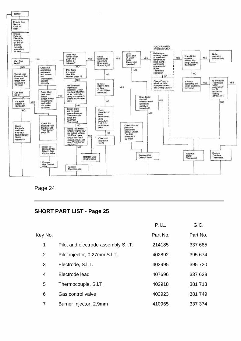
FIG. 21. FAULT FINDING CHART
Page 24
SHORT PART LIST - Page 25
P.I.L. G.C.
Key No. Part No. Part No.
1 Pilot and electrode assembly S.l.T. 214185 337 685
2 Pilot injector, 0.27mm S.l.T. 402892 395 674
3 Electrode, S.l.T. 402995 395 720
4 Electrode lead 407696 337 628
5 Thermocouple, S.l.T. 402918 381 713
6 Gas control valve 402923 381 749
7 Burner Injector, 2.9mm 410965 337 374
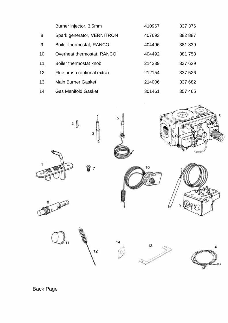
Burner injector, 3.5mm 410967 337 376
8 Spark generator, VERNITRON 407693 382 887
9 Boiler thermostat, RANCO 404496 381 839
10 Overheat thermostat, RANCO 404492 381 753
11 Boiler thermostat knob 214239 337 629
12 Flue brush (optional extra) 212154 337 526
13 Main Burner Gasket 214006 337 682
14 Gas Manifold Gasket 301461 357 465
Back Page

Page 25