Embed Size (px)
Citation preview
INTERNATIONAL JOURNAL OF PROFESSIONAL ENGINEERING STUDIES Volume 10 /Issue 2 / SEP 2019
IJPRES
CFD ANALYSIS OF A CENTRIFUGAL PUMP BY USING NON-NEWTONIAN FLUIDS
1Revnth kumar Yepuri (M.Tech) 2 Dr. Mahesh Mallampati Professor 3Dr.C.Govinda Rajulu Head of the dept 1,2,3 Guntur Engineering College, Yanamadala, Andhra Pradesh, , INDIA
1revnth.yepuri @Gmail.Com [email protected] [email protected]
ABSTRACT
Centrifugal pumps are a sub-class of dynamic axisymmetric work-absorbing turbo machinery. Centrifugal pumps are used to transport fluids by the conversion of rotational kinetic energy to the hydrodynamic energy of the fluid flow. The rotational energy typically comes from an engine or electric motor. The fluid enters the pump impeller along or near to the rotating axis and is accelerated by the impeller, flowing radially outward into a diffuser or volute chamber (casing), from where it exits. Common uses include water, sewage, petroleum and petrochemical pumping; a centrifugal fan is commonly used to implement a vacuum cleaner. The reverse function of the centrifugal pump is a water turbine converting potential energy of water pressure into mechanical rotational energy.
The purpose of this paper is to identify /observe and determine the pattern of velocity profile and pressure distribution by using CFD solid works simulation module by using non-Newtonian fluids, such as olive oil, and slurry after the 3D design and modeling of the pump is made using solid works 2016 software. Basically, this paper revolves around the idea of investigating the effect and distribution of velocity profile and pressure within a pump by using water and non-Newtonian fluids.
1.INTRODUCTION
A Centrifugal pump is a mechanical device for moving air or other gases or fluid. They use the kinetic energy of the impellers or the rotating blade to increase the pressure of the air/gas/liquid stream
which in turn moves them against the resistance caused by ducts, dampers and other components. Centrifugal fans accelerate air radically, changing the direction (typically by 90°) of the airflow. They are sturdy, quiet, reliable, and capable of operating over a wide range of conditions.
Centrifugal pump are constant displacement devices or constant volume devices, meaning that, at a constant fan speed, a centrifugal fan will pump a constant volume of air or water rather than a constant mass. This means that the velocity in a system is fixed even though mass flow rate through the fan is not.Centrifugal pumps which belong to wider group of fluid machines called turbo machines are the most common type of pump used to move liquids through a piping system. The fluid enters the pump impeller along or near to the rotating axis and is accelerated by the impeller, flowing radially outward or axially into a diffuser or volute chamber, from where it exits into the downstream piping system. Centrifugal pumps are typically used for large discharge through smaller heads.
2. WORKING PRINCPLE
A centrifugal pump is also known as a Roto-dynamic pump or dynamic pressure pump. It works on the principle of centrifugal force. In this type of pump, the liquid is subjected to whirling motion by the rotating impeller which is made of a number of backward curved vanes. The liquid enters this impeller at its center or the eye and gets discharged into the casing enclosing the outer edge of the impeller. The rise in the pressure head at any
INTERNATIONAL JOURNAL OF PROFESSIONAL ENGINEERING STUDIES Volume 10 /Issue 2 / SEP 2019
IJPRES
point/outlet of the impeller is Proportional to the square of the tangential velocity of the liquid at that point Hence at the outlet of the impeller where the radius is more the rise In pressure head will be more and the liquid will be discharged at the outlet with a high pressure head. Due to this high-pressure head, the liquid can be lifted to a higher level. that has been widely used in industry is the most typical type of fluid machinery that transforms machinery energy into fluid pressure and kinetic energy via impellers. A centrifugal pump, the most common type of pumps, has been used in industrial areas, such as water, sewage, drainage, and the chemical industry. Accordingly, numerous studies have been performed for the designs of various models of centrifugal pumps. Due to the needs of the industry, optimization using mechanical concepts has recently been studied in order to make higher efficiency pumps with higher heads. An impeller, among all of the components of the pump, has the biggest influence on performance, since fluid flow in the pump generates energy through it.
3. CLASSIFICATION
3.1 TYPES OF CENTRIFUGAL PUMP
Vertical centrifugal pump:
Vertical centrifugal pumps are also referred to as cantilever pumps. They utilize a unique shaft and bearing support configuration that allows the volute to hang in the sump while the bearings are outside the sump. This style of pump uses no stuffing box to seal the shaft but instead utilizes a "throttle bushing". A common application for this style of pump is in a part washer.
Froth pumps:
In the mineral industry, or in the extraction of oil sand, froth is generated to separate the rich minerals or bitumen from the sand and clays. Froth contains air that tends to block conventional pumps and cause loss of prime. Over history, industry has developed different ways to deal with this problem. In the pulp and paper industry holes are drilled in the impeller. Air escapes to the back of the impeller and a special expeller discharges the air back to the suction tank. The impeller may also feature special small vanes between the primary vanes called split vanes or
secondary vanes. Some pumps may feature a large eye, an inducer or recirculation of pressurized froth from the pump discharge back to the suction to break the bubbles.
4. PROBLEMS OF CENTRIFUGAL PUMP
These are some difficulties faced in centrifugal pumps.
Cavitations the net positive suction head (NPSH) of the system is too low for the selected pump
Wear of the impeller can be worsened by suspended solids
Corrosion inside the pump caused by the fluid properties
Overheating due to low flow Leakage along rotating shaft. Lack of prime centrifugal pumps must be filled
(with the fluid to be pumped) in order to operate Surge
4.1 Priming:
Most centrifugal pumps are not self-priming. In other words, the pump casing must be filled with liquid before the pump is started, or the pump will not be able to function. If the pump casing becomes filled with vapors or gases, the pump impeller becomes gas-bound and incapable of pumping. To ensure that a centrifugal pump remains primed and does not become gas-bound, most centrifugal pumps are located below the level of the source from which the pump is to take its suction. The same effect can be gained by supplying liquid to the pump suction under pressure supplied by another pump placed in the suction line.
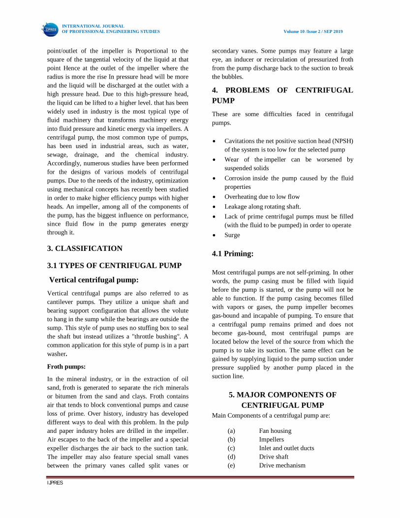
5. MAJOR COMPONENTS OF CENTRIFUGAL PUMP
Main Components of a centrifugal pump are:
(a) Fan housing (b) Impellers (c) Inlet and outlet ducts (d) Drive shaft (e) Drive mechanism
INTERNATIONAL JOURNAL OF PROFESSIONAL ENGINEERING STUDIES Volume 10 /Issue 2 / SEP 2019
IJPRES
Other components used may include bearings, couplings, impeller locking device, fan discharge casing, shaft seal plates etc.
Components of a centrifugal pump
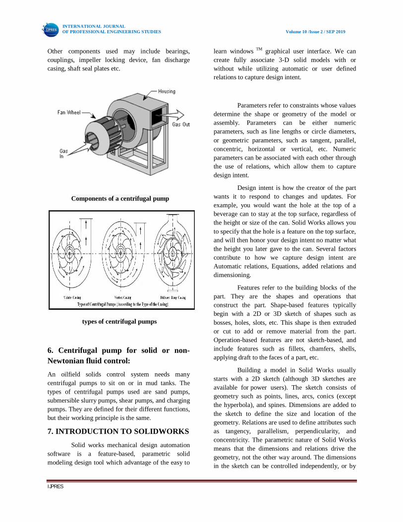
types of centrifugal pumps
6. Centrifugal pump for solid or non-Newtonian fluid control:
An oilfield solids control system needs many centrifugal pumps to sit on or in mud tanks. The types of centrifugal pumps used are sand pumps, submersible slurry pumps, shear pumps, and charging pumps. They are defined for their different functions, but their working principle is the same.
7. INTRODUCTION TO SOLIDWORKS
Solid works mechanical design automation software is a feature-based, parametric solid modeling design tool which advantage of the easy to
learn windows TM graphical user interface. We can create fully associate 3-D solid models with or without while utilizing automatic or user defined relations to capture design intent.
Parameters refer to constraints whose values determine the shape or geometry of the model or assembly. Parameters can be either numeric parameters, such as line lengths or circle diameters, or geometric parameters, such as tangent, parallel, concentric, horizontal or vertical, etc. Numeric parameters can be associated with each other through the use of relations, which allow them to capture design intent.
Design intent is how the creator of the part wants it to respond to changes and updates. For example, you would want the hole at the top of a beverage can to stay at the top surface, regardless of the height or size of the can. Solid Works allows you to specify that the hole is a feature on the top surface, and will then honor your design intent no matter what the height you later gave to the can. Several factors contribute to how we capture design intent are Automatic relations, Equations, added relations and dimensioning.
Features refer to the building blocks of the part. They are the shapes and operations that construct the part. Shape-based features typically begin with a 2D or 3D sketch of shapes such as bosses, holes, slots, etc. This shape is then extruded or cut to add or remove material from the part. Operation-based features are not sketch-based, and include features such as fillets, chamfers, shells, applying draft to the faces of a part, etc.
Building a model in Solid Works usually starts with a 2D sketch (although 3D sketches are available for power users). The sketch consists of geometry such as points, lines, arcs, conics (except the hyperbola), and spines. Dimensions are added to the sketch to define the size and location of the geometry. Relations are used to define attributes such as tangency, parallelism, perpendicularity, and concentricity. The parametric nature of Solid Works means that the dimensions and relations drive the geometry, not the other way around. The dimensions in the sketch can be controlled independently, or by
INTERNATIONAL JOURNAL OF PROFESSIONAL ENGINEERING STUDIES Volume 10 /Issue 2 / SEP 2019
IJPRES
relationships to other parameters inside or outside of the sketch.
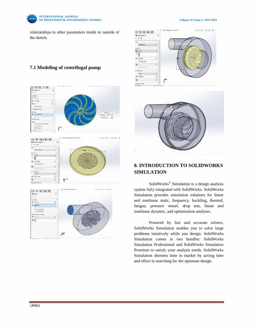
7.1 Modeling of centrifugal pump
8. INTRODUCTION TO SOLIDWORKS SIMULATION
SolidWorks® Simulation is a design analysis system fully integrated with SolidWorks. SolidWorks Simulation provides simulation solutions for linear and nonlinear static, frequency, buckling, thermal, fatigue, pressure vessel, drop test, linear and nonlinear dynamic, and optimization analyses.
Powered by fast and accurate solvers, SolidWorks Simulation enables you to solve large problems intuitively while you design. SolidWorks Simulation comes in two bundles: SolidWorks Simulation Professional and SolidWorks Simulation Premium to satisfy your analysis needs. SolidWorks Simulation shortens time to market by saving time and effort in searching for the optimum design.
INTERNATIONAL JOURNAL OF PROFESSIONAL ENGINEERING STUDIES Volume 10 /Issue 2 / SEP 2019
IJPRES
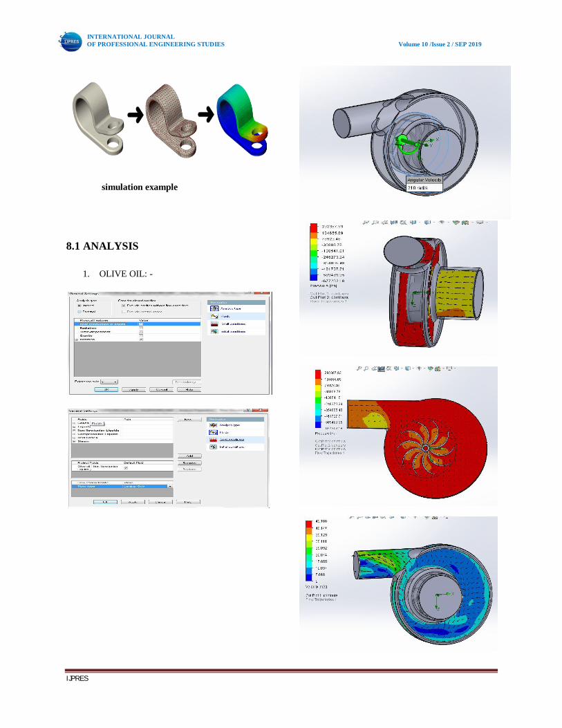
simulation example
8.1 ANALYSIS
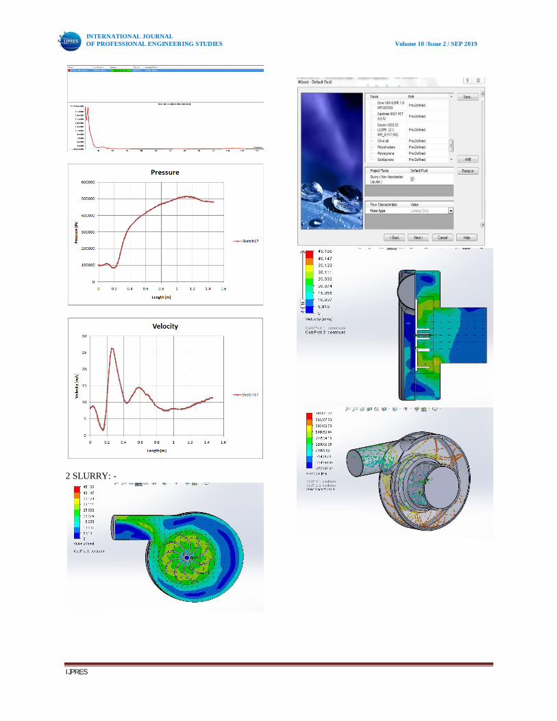
1. OLIVE OIL: -
INTERNATIONAL JOURNAL OF PROFESSIONAL ENGINEERING STUDIES Volume 10 /Issue 2 / SEP 2019
IJPRES
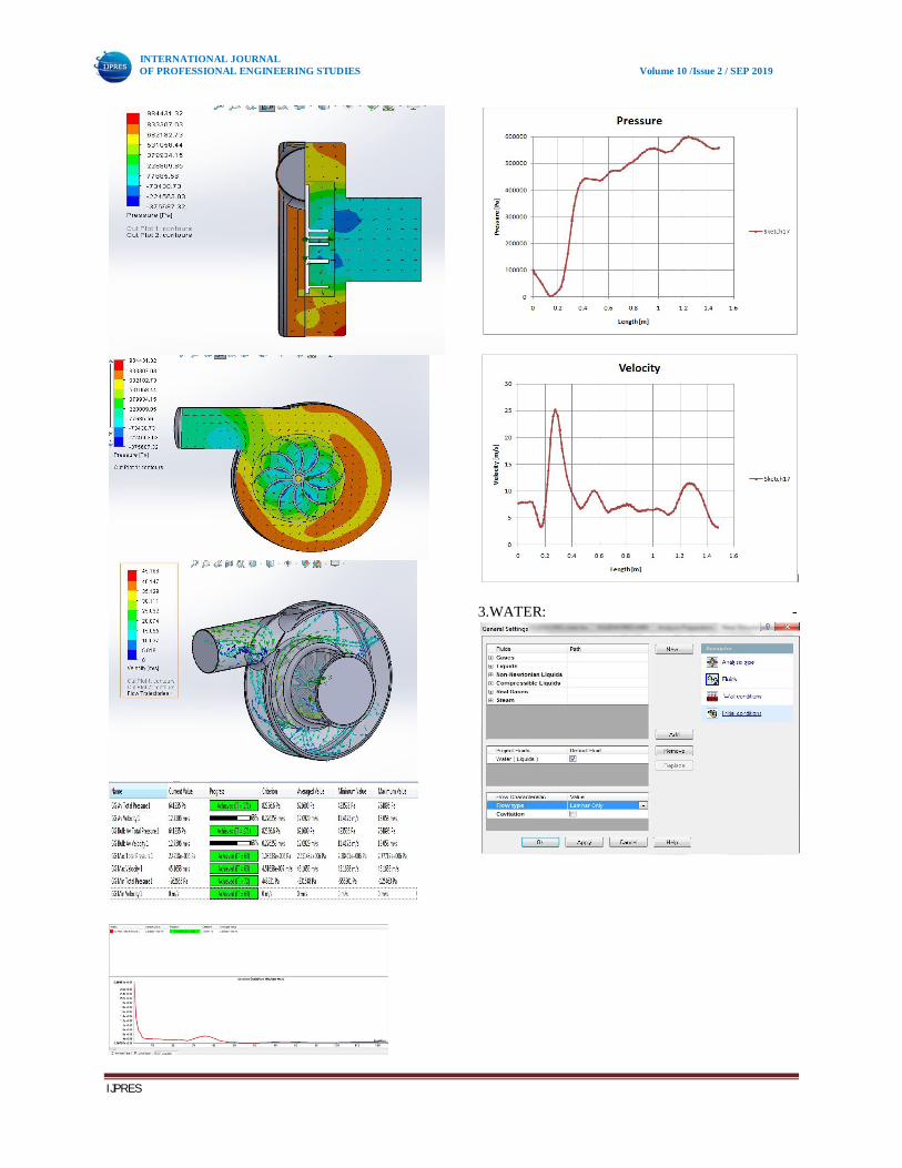
2 SLURRY: -
INTERNATIONAL JOURNAL OF PROFESSIONAL ENGINEERING STUDIES Volume 10 /Issue 2 / SEP 2019
IJPRES
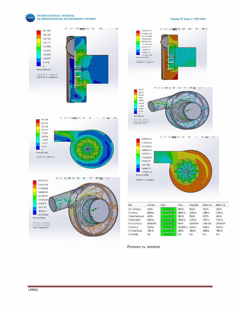
3.WATER: -
INTERNATIONAL JOURNAL OF PROFESSIONAL ENGINEERING STUDIES Volume 10 /Issue 2 / SEP 2019
IJPRES
Pressure vs. iteration
INTERNATIONAL JOURNAL OF PROFESSIONAL ENGINEERING STUDIES Volume 10 /Issue 2 / SEP 2019
IJPRES
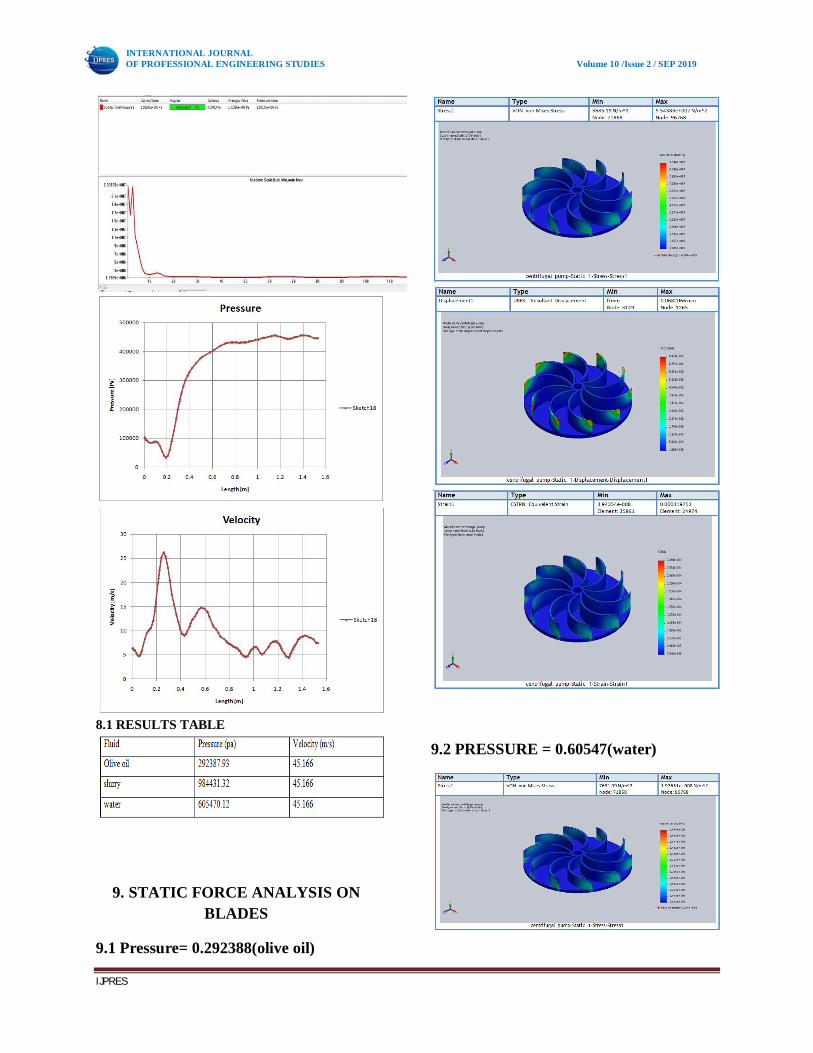
8.1 RESULTS TABLE
9. STATIC FORCE ANALYSIS ON BLADES
9.1 Pressure= 0.292388(olive oil)
9.2 PRESSURE = 0.60547(water)
INTERNATIONAL JOURNAL OF PROFESSIONAL ENGINEERING STUDIES Volume 10 /Issue 2 / SEP 2019
IJPRES
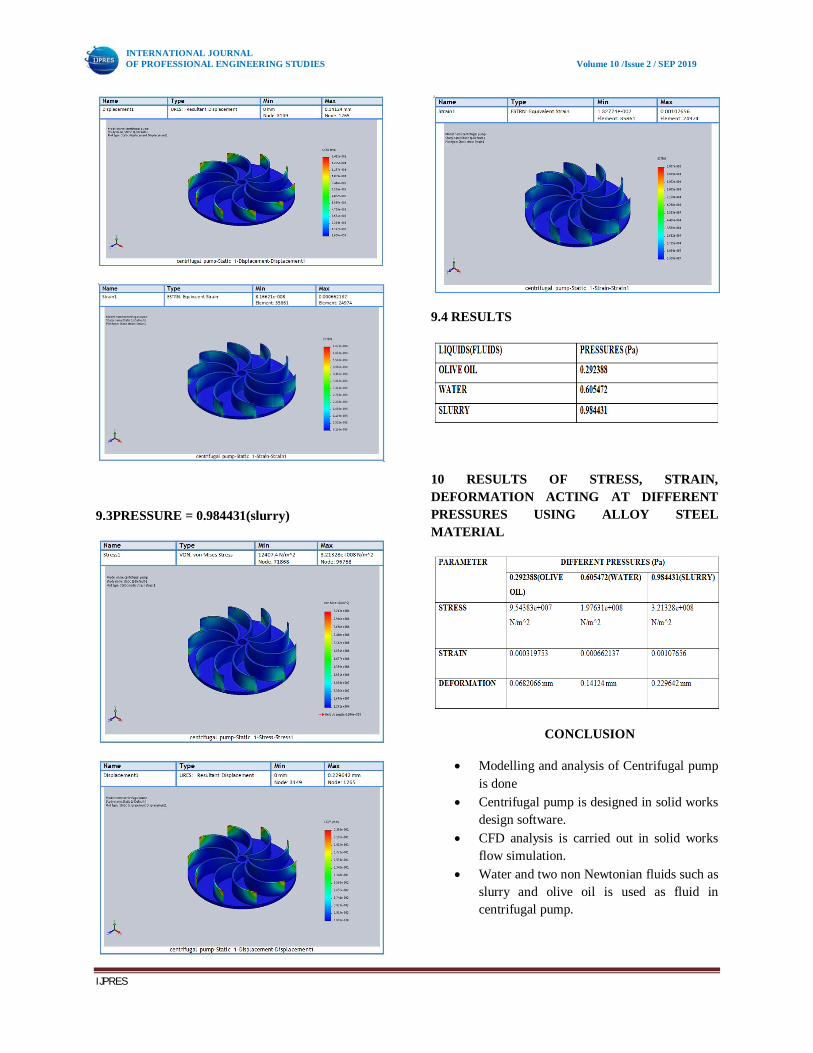
9.3PRESSURE = 0.984431(slurry)
9.4 RESULTS
10 RESULTS OF STRESS, STRAIN, DEFORMATION ACTING AT DIFFERENT PRESSURES USING ALLOY STEEL MATERIAL
CONCLUSION
Modelling and analysis of Centrifugal pump is done
Centrifugal pump is designed in solid works design software.
CFD analysis is carried out in solid works flow simulation.
Water and two non Newtonian fluids such as slurry and olive oil is used as fluid in centrifugal pump.
INTERNATIONAL JOURNAL OF PROFESSIONAL ENGINEERING STUDIES Volume 10 /Issue 2 / SEP 2019
IJPRES
Pressure and velocity trajectories inside the pump are shown values are noted and tabulated.
The pressure acting on blades thus stress strain and deformation is also distributed on blades.
The stress strain and deformation at each pressure is determined.
The maximum pressure is for the olive oil fluid.
References
1. Design of a mixed flow pump impeller and its validation using FEM analysis By Sambhrant Srivastava, Apurb Kumar Roy and Kaushik KumarResearch Scholar, Department of Mechanical Engineering, Birla Institute of Technology, Mesra, Ranchi, 835215 India © 2014 The Authors. Published by Elsevier Ltd
2. Design and Analysis on Hydraulic Model of The Ultra -low Specific-speed Centrifugal Pump presented in International Conference on Advances in Computational Modeling and Simulation By Jie Jina Ying Fana Wei Hana Jiaxin Hub Available online at www.sciencedirect.com Procedia Engineering 31 2012 (110 – 114)
3. Optimum design on impeller blade of mixed-flow pump based on CFD, presented in International Conference on Advances in Computational Modeling and Simulation By Jidong Lia, Yongzhong Zenga, Xiaobing Liua, Huiyan Wanga © 2011 Published by Elsevier Ltd.
4 Numerical study of the effects of some geometric characteristics of a centrifugal pump impeller that pumps a viscous fluid. presented by M.H. Shojaeefard, M. Tahani, M.B. Ehghaghi , M.A. Fallahian, M. Beglari Department of Mechanical Engineering, Tabriz University, Tabriz, Iran Available online 7 March 2012
5 Improving centrifugal pump efficiency by impeller trimming By Mario Šavar Hrvoje Kozmar Igor Sutlović University of Zagreb, Faculty of Mechanical Engineering and Naval Architecture, Contents lists
available at ScienceDirect Available online 6 October 2009
6 Estimation of radial load in centrifugal pumps using computational fluid dynamics by R. Barrio , J. Fernández , E. Blanco J. Parrondo a Departamento de Energía, Universidad de Oviedo, Campus de Viesques, 33203 Gijón, Asturias, Spain Available online 14 January 2011 Contents lists available at Science Direct
7. S.Rajendranand Dr.K.Purushothaman, “Analysis of a centrifugal pump impeller using ANSYS - CFX,” International Journal of Engineering Research & Technology, Vol. 1 Issue 3, 2012.
8. S R Shah, S V Jain and V J Lakhera, “CFD based flow analysis of centrifugal pump,” Proceedings of the 37th National & 4th
9. E.C. Bacharoudis, A.E. Filios, M.D. Mentzos and D.P. Margaris, “Parametric Study of a Centrifugal Pump Impeller by Varying the Outlet Blade Angle,” The Open Mechanical Engineering Journal, no 2, 75-83, 2008.
10. Somashekar and Dr. H. R. Purushothama, “Numerical Simulation of Cavitation Inception on Radial Flow Pump,” IOSR Journal of Mechanical and Civil Engineering, Vol. 1, Issue 5, pp. 21- 26,2012.
11 Liu Houlin, Wang Yong, Yuan Shouqi, Tan Minggao and Wang Kai, “Effects of Blade Number on Characteristics of Centrifugal Pumps,” Chinese journal of mechanical engineering, Vol. 23, 2010.