Embed Size (px)
Citation preview
i
CFD Analysis of a vertical tube having internal fins for
the Natural Convection
A project report submitted in the partial fulfillment of the requirements for the degree of
Bachelor of Technology
(Mechanical Engineering)
By
Shashank Deorah
Roll No. 108ME081
Department of Mechanical Engineering
National Institute of Technology, Rourkela
2012
ii
CFD Analysis of a vertical tube having internal fins for
the Natural Convection
A project report submitted in the partial fulfillment of the requirements for the degree of
Bachelor of Technology
(Mechanical Engineering)
By
Shashank Deorah
Roll No. 108ME081
Under the supervision of
Prof. Ashok Ku. Satapathy
Associate Professor
Department of Mechanical Engineering
NIT Rourkela
Department of Mechanical Engineering
National Institute of Technology, Rourkela
2012

iii
National Institute of Technology
Rourkela
C E R T I F I C A T E This is to certify that the work in this thesis entitled “CFD analysis of natural
convection through vertical tube with internal helical fins” by Shashank
Deorah, has been carried out under my supervision in partial fulfillment of the
requirements for the degree of Bachelor of Technology in Mechanical
Engineering during session 2011-2012 in the Department of Mechanical
Engineering, National Institute of Technology, Rourkela.
To the best of my knowledge, this work has not been submitted to any other
University/ Institute for the award of any degree or diploma.
Prof. Ashok Ku. Satapathy
(Supervisor)
Associate Professor
Department of Mechanical Engineering
NIT, Rourkela
iv
ACKNOWLEDGEMENT
I would like to express my deep sense of gratitude and respect to my
supervisor Prof. ASHOK SATAPATHY for his excellent guidance, valuable
suggestions and endless support.
I am also thankful to Prof. K.P. MAITY, H.O.D, Department of
Mechanical Engineering, N.I.T Rourkela for his constant support and
encouragement.
Last, but not the least I extend my sincere thanks to other faculty
members of the Department of Mechanical Engineering, NIT Rourkela, for their
valuable advice in every stage for successful completion of this project report.
Shashank Deorah
108ME081
Mechanical Engineering Department
National Institute of Technology, Rourkela
v
CONTENTS
Chapter 1 1
1. Introduction 2
Chapter 2 4
2. Literature survey 5
Chapter 3 8
3. Theory 9
3.1 Natural Convection 9
3.2 Fluid flow 10
3.3 Dimensionless parameters 12
Chapter 4 14
4. Theoretical formulation 15
4.1 Rectangular fin 15
4.2 Parabolic fin 16
4.3 Trapezoidal fin 18
4.4 Fin effectiveness 19
4.5 Fin efficiency 19
Chapter 5 20
5. Results and discussion 20
5.1 Temperature contours for different tubes 24
5.2 Surface Nusselt number 29
5.3 Surface heat transfer coefficient 32
5.4 Heat transfer rate 35
Chapter 6 36
6. Conclusion 37
References 38
vi
Nomenclature
Wall temperature
Surrounding temperature
k Thermal conductivity
Surface heat transfer coefficient
Boundary layer thickness
β Coefficient of thermal expansion
ρ Density
X Vertical distance
R Radial distance
U Axial velocity of liquid
V Radial velocity of liquid
g Acceleration due to gravity
ν Kinematic viscosity
α Thermal diffusivity
Cross sectional area
Surface area
Q Rate of heat flux
Fin efficiency
Bessel function
vii
ABSTRACT
The heat transfer rate to a fluid flowing in pipe can be enhanced by the use of internal fins. This
thesis concerned with computer simulation study of vertical tube with helical fins used to
enhance their heat transfer performance subjected to natural convection heat transfer. All the
main parameters which can significantly influence the heat transfer performance of finned tube
has been analyzed. Natural convection in a vertical tube without fins was taken as the reference
tube and different fin patterns such as a single fin with large no. of turns like coiled shape and
large no. of fins with single turn is compared with reference tube on the basis of different
parameters such as heat transfer rate, surface nusselt number, heat transfer coefficient, fin
effectiveness etc. There are some dimensionless numbers which affect the natural convection
such as nusselt number which is the function of Reynolds number, grashof number and prandlt
number, Rayleigh number which is the product of grashoff and prandtl number. After getting
best fin configuration compared it with different fin profile such as rectangular cross section,
tapered fin with trapezoidal cross section and hyperbolic cross section. All the computer
simulation has been done on the ANSYS 13.0 . The Navier-stokes equations were used to solve
for the fluid flow inside the tube and the Boussinesq approximation was used to get the
buoyancy effect. Aluminium is used for the fin material and air is taken as the fluid flowing
inside the tube and the flow is taken as laminar. It was found that the large number of fins with
single turn is more efficient then other fin patterns, as there is less flow resistance, high heat
transfer rate.

1
CHAPTER~1

2
1. INTRODUCTION
Convection is a process which involves mass movement of fluids. Natural convection occurs due
to temperature difference which produces the density difference which results in mass
movement, this process is called natural or free convection. For example, assume a plate which
is maintained isothermal at temperature and the surrounding temperature is . On
getting heated, the fluid near the wall moves up due to the effect of buoyancy and this hot fluid
is replaced by cold fluid moving towards the wall. Hence a circular current is set up due to
density difference. There is a boundary layer adjacent to the plate where the velocity and
temperature and velocity vary from plate to free stream. Initially the velocity increase with
increasing distance from the surface and reaches a maximum and then decrease to approach
zero value. This is because of action of viscosity diminishes rapidly with distance from plate,
while density difference decreases more slowly.
The used of heat transfer enhancement has become widespread during the last so many years.
The need of heat transfer enhancement is to reduce the size and cost of heat exchanger
equipment, or increase the heat duty for a give size heat exchanger. This goal can be achieve in
two ways active and passive enhancement. The active enhancement is less common because it
requires addition of external power (e.g., an electromagnetic field) to cause a desired flow
modification. In the passive enhancement, it consists of alteration to the heat transfer surface
or incorporation of a device whose presence results in a flow field modification. The most
popular enhancement is the fin.
Fins are the extended surfaces which are used to enhance the rate of heat transfer dissipation
from heated surfaces to air. Fins can be placed on plane surfaces, tubes, or other geometries.
These surfaces have been used to increase heat transfer rate by adding additional surface area
3
and encouraging mixing. When number of fins are used to enhance heat transfer under natural
convection conditions the optimum geometry of fins (corresponding to a maximum rate of heat
transfer) should be used, provided this is compatible with available space and financial
limitations. The common fins used extensively to increase the rates of natural convection heat
transfer from systems are rectangular fins because such fins are simple and cheap, to
manufacture. The heat transfer to the fluid flowing through a cylindrical pipe by the heat
dissipating surfaces can be obtained mainly by using the mechanisms of heat transfer by forced
convection, natural convection and by radiation heat transfer. This paper mainly concerned
with those issues related to the heat transfer obtained mainly by natural convection.
A great number of experimental and analytical work has been done on vertical and horizontal
finned tube subjected to natural convection. Kayansayan [2] studied the thermal characteristic
of fin and tube heat exchanger, Rao [3] studied the heat transfer from horizontal fin array, Yang
[4] conducted an experiment on mixed convective cooling of a fin in a channel, Sharif and
Bergman [5] worked on enhancement of PCM melting in enclosure with horizontal finned
internal surface. Myhren [6] worked on improving thermal performance of ventilation radiators
using internal fins. Baek [7] studied on heat transfer enhancement using straight and twisted
internal fins.
Applications of internal fins
1. Internal fins are used in compact heat exchangers.
2. Internal fins are used in phase change material storages (PCM). PCM are used to balance
the temporary temperature alteration and to store energyin several practical fields like
automobile industries.
3. The rate of heat transfer from fluid flowing through the microchannels can be greatly
enhanced by use of internal fins.
4. Internal fins used in Improving the thermal performance of ventilation radiators.

4
CHAPTER~2
5
2. LITERATURE SURVEY
Muñoz et al. [8] done analytical work on internal helically finned tubes for parabolic trough
design by CFD tools. The application of finned tubes to the design of parabolic trough collectors
has some losses as the pressure losses, thermal losses and thermo-mechanical stress and
thermal fatigue. The result shows an improvement potential in parabolic trough solar plants
efficiency by the application of internal finned tubes.
SAZALI [9] experimental study of a vertical internally finned tube subjected to natural
convection heat transfer. The length of tube was 100mm. the tube taken for the experiment
has inner diameter 80mm and the outer diameter 90mm. The tube contains four radial,
straight, and equally spaced around the circumference of the tube. Other dimensions like
height of the fins are 100mm and the length of the fins are 25mm. Air was used as a working
fluid in the experiment. The result shows that the value of Nu for vertical cylinder under
variables time varies with the temperature is increasing.
Myhren et al. [6] studied heat output optimization of a ventilation radiator by varying the
distribution of vertical, longitudinal convection fins. The investigation was made using
Computational Fluid Dynamics simulations while analytical calculations were used for different
flow and heat transfer mechanisms. The results showed that heat transfer can be increased in
the section where ventilation air is brought into the room by slightly changing the geometry of
the fins like decreasing the fin to fin distance. The small change in internal design could mean
considerable increase in thermal efficiency for the ventilation radiator as a whole.
Wang et al. [10] studied heat transfer performance of internally finned tubes with blocked core-
tube was numerically investigated by the realizable k–e turbulence model with wall function
6
method using FLUENT. By using 3 kinds of lateral fin profiles, S-shape, Z-shape and V-shape,
were studied and compared. The corresponding correlations of Nusselt number and friction
factor were obtained for different-shape internally finned tubes. The result showed that tubes
with S-shape fins and Z-shape fins were best profile as compared with V-shape fins, and
moreover, tube with Z-shape fins had the best performance.
Giri et al. [11] worked on the role of natural convection in many applications like ice-storage
air-conditioning. A mathematical formulation of natural convection heat and mass transfer over
a shrouded vertical fin array is developed. The base plate were kept at a temperature below the
dew point of the surrounding moist air due to this, occurrence of condensation of moisture on
the base plate, while the fins may be partially or fully wet. The results showed that beyond a
certain stream wise distance, further fin length does not improve the sensible and latent heat
transfer performance, and that if dry fin analysis is used under moisture condensation
conditions, the overall heat transfer will be lowballed by about 50% even at low buoyancy
ratios.
Papadopoulous et al. [12] done the Numerical study of laminar fluid flow in a curved elliptic
duct with internal fins. The study of the fully developed laminar incompressible flow inside a
curved duct of elliptical cross-section with four thin and internal longitudinal fins is done using
the improved CVP method. Results showed that the friction factor increases for large fins and
for high Dean numbers and in some cases, it has dependent on the cross-sectional aspect ratio.
The thermal results show that the heat transfer rate is increased by the internal fins and that it
depends on the aspect ratio.
Foong et al. [13] conducted the numerical study to investigate the fluid flow and heat transfer
characteristics of a square micro channel with four longitudinal internal fins. 3-D numerical
simulations were performed on the micro channel with variable fin height ratio in the presence
of a developed laminar flow. Constant heat flux boundary conditions were assumed on the
external walls of the square micro channel. Results obtained of the average local Nusselt
7
number distribution along the channel length are as a function of the fin height ratio. The
analytical study was carried out for different fin heights and flow parameters.
Aziz [14] et al. measured the heat transfer rate for different fin profile such as rectangular,
trapezoidal, and concave parabolic (finite tip thickness). Results obtained from the comparison
based on the relationship between the dimensionless heat flux, the fin parameter, and
dimensionless tip temperature for all three geometries.

8
CHAPTER~3
9
3. THEORY
The science of heat transfer is concerned with the generation, use, exchange, and conversion
of heat and thermal energy between physical systems. Heat transfer is the discipline of thermal
engineering that concerns the calculation of rate at which heat flows within the medium, across
the interface or from one surface to another. There are different modes of heat transfer which
includes:
a. Heat transfer through conduction
b. Heat transfer through convection
c. Heat transfer through radiation
3.1 Natural convection
Convective heat transfer is the transfer of heat from one place to another place by the fluid
movement. Convection is usually occurred in liquids and gases. The causes of convection can be
described as either natural (free) or forced convection. The difference between natural and
forced convection is important for heat transfer through convection. The main cause of Natural
convection or free convection is due to temperature differences which affect the density and
the relative buoyancy of the fluid. Heavier components move down while the lighter
components rise which leads to fluid movement. Hence gravitational field plays an important
role in natural convection. The examples of natural convection is the rise of smoke from a fire,
boiling water in the pot in which the hot and less dense water from the bottom layer moves
downward and the cool and high dense water moves upward to the top of the pot. Natural
convection will occur due to variation in density between the two fluids, the acceleration due to
gravity that drives the convection to a larger distance through the convecting medium.The of
convection can be determined by the Rayleigh number (Ra).
Consider a plate maintained isothermal at temperature and the surrounding temperature is
. The fluid near the wall moves up on getting heated because of the effect of buoyancy and
this hot fluid is replaced by the cold fluid moving towards the wall. Thus there is a loop creates
10
due to the density difference. There will always be a boundary layer adjacent to the wall, either
in the natural convection or forced convection, where the temperature and velocity vary from
plate to the free stream.
The thermal boundary layer is considered as the stationary fluid film which is responsible for
heat conduction and then heat is transported by fluid motion.
Heat transfer rate from wall to fluid is :
(1)
Thermal boundary layer thickness is defined as the thickness at which:
(2)
Let
(3)
The rate of heat transfer Qc increase with increase in value of heat transfer coefficient hc. On
increasing the velocity of fluid, the film thickness decreases and value of heat transfer
coefficient increases.
3.2 Fluid flow
All the numerical simulation done on the CFD for the fluid flow were based on the Navier-
stokes Equation. Donaldson [15] worked on the free convection in the case of vertical cylinder
with linear wall temperature gradient. The equations which describe the problem of steady

11
natural convection about a vertical cylinder of radius R with a prescribed wall temperature, are
as follows:
Density variation with temperature is:
(4)
The equation of continuity, momentum and energy in cylindrical co-ordinates which apply to
the fluid flow with boundary conditions are:
Continuity equation:
(5)
Momentum equation:
(6)
Energy equation:
(7)
Where X is vertical distance measured upward from origin, R is radial distance, U is the axial
velocity upward of the fluid, V is the radial velocity of the fluid.
Boundary conditions are as follows:
U=0, V=0 : at R=a,
U=0 : at X=0,
T=Ts(X) : at R=a,
T=To : at X=0, (8)
From boundary conditions, we can see that equation (6) reduce to
(9)
12
From equation (7) and (9)
(10)
3.3 Dimensionless parameters
Reynolds number:
The Reynolds number (Re) [16][17] is a dimensionless number which is defined as the
ratio of inertial forces to viscous force.
Prandtl number:
Prandtl number is the ratio of kinematic or momentum diffusivity ( ) to the thermal diffusivity
(
Grashoff number:
Grashoff number is the ratio of buoyancy force to the viscous force acting on the fluid.
Rayleigh number:
Rayleigh number is the product of grashoff number and the prandtl number. In natural
convection Rayleigh number is used instead of grashoff number to correlate heat transfer.
13
Nusselt number:
The Nusselt number is defined as the ratio of convective to conductive heat transfer across
the boundary.
In natural convection, the transition from laminar to turbulent flow is determine by critical
value of grshoff number.
When,
, Forced convection
, Natural convection
, Natural and forced convection are of same order of
Magnitude

14
CHAPTER ~4
15
4. Theoretical Formulation
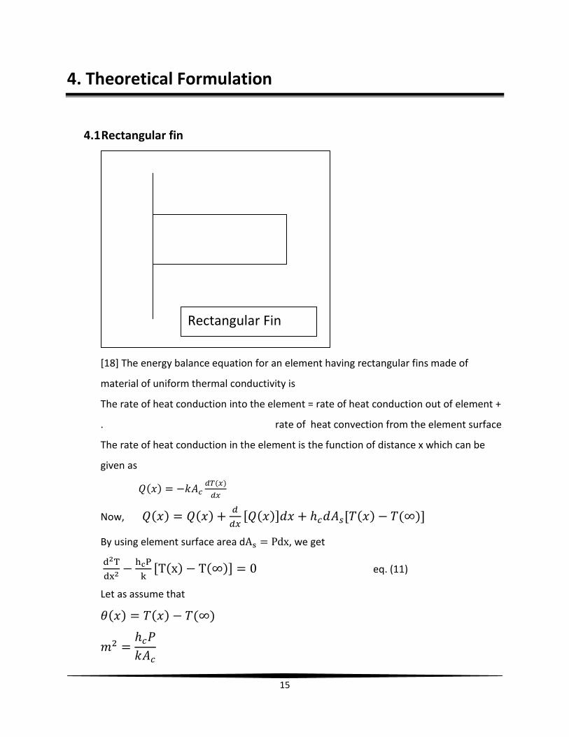
4.1 Rectangular fin
[18] The energy balance equation for an element having rectangular fins made of
material of uniform thermal conductivity is
The rate of heat conduction into the element = rate of heat conduction out of element +
. rate of heat convection from the element surface
The rate of heat conduction in the element is the function of distance x which can be
given as
Now,
By using element surface area d , we get
eq. (11)
Let as assume that
Rectangular Fin
16
Hence eq. (11) becomes
eq. (12)
The general solution of this equation is
eq. (13)
Let us assume that the fin is of finite length and loss of heat from its tip is convective.
The boundary conditions are:
By using this boundary condition and rearranging the equation, we get
And,
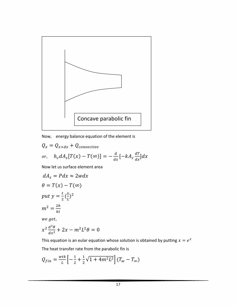
4.2 Parabolic Fin
[18] Let us consider a fin has length ‘L’, thickness ‘t’ which is at the base and width ‘w’
which is perpendicular to the plane of the paper has base temperature and
surrounding temperature . consider the thickness is the function of x.
is the surface area and is the cross sectional area.
The eq. of the profile of the fin is
At x=0, y=0
X=L, y=
17
Now, energy balance equation of the element is
Now let us surface element area
This equation is an eular equation whose solution is obtained by putting
The heat transfer rate from the parabolic fin is
Concave parabolic fin

18
In the designing of parabolic fins the following observations should be noted
carefully:
1. The fin must have the minimum material for the most economical fins.
2. The heat flux is independent of fin thickness, and heat conduction rate is
independent of distance from the fin base.
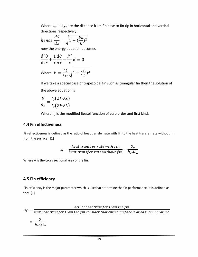
4.3 Trapezoidal fin
[19] Consider a trapezoidal fin of cross sectional area A, surface S, length L. For
variable fin area energy balance equation is at a distance x from the fin base is given
as:
Where, A is the cross sectional area and S is the surface area of the element.
Trapezoidal fin
19
Where are the distance from fin base to fin tip in horizontal and vertical
directions respectively.
now the energy equation becomes
Where,
If we take a special case of trapezoidal fin such as triangular fin then the solution of
the above equation is
Where is the modified Bessel function of zero order and first kind.
4.4 Fin effectiveness
Fin effectiveness is defined as the ratio of heat transfer rate with fin to the heat transfer rate without fin
from the surface. [1]
Where A is the cross sectional area of the fin.
4.5 Fin efficiency
Fin efficiency is the major parameter which is used yo determine the fin performance. It is defined as
the: [1]

20
CHAPTER~5
21
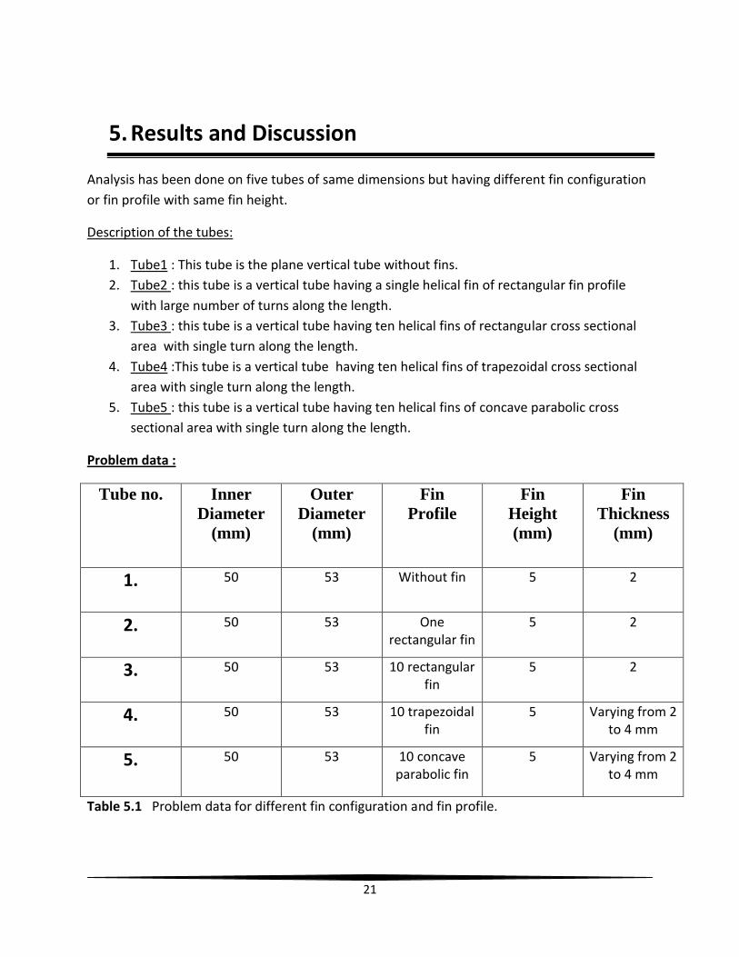
5. Results and Discussion
Analysis has been done on five tubes of same dimensions but having different fin configuration
or fin profile with same fin height.
Description of the tubes:
1. Tube1 : This tube is the plane vertical tube without fins.
2. Tube2 : this tube is a vertical tube having a single helical fin of rectangular fin profile
with large number of turns along the length.
3. Tube3 : this tube is a vertical tube having ten helical fins of rectangular cross sectional
area with single turn along the length.
4. Tube4 :This tube is a vertical tube having ten helical fins of trapezoidal cross sectional
area with single turn along the length.
5. Tube5 : this tube is a vertical tube having ten helical fins of concave parabolic cross
sectional area with single turn along the length.
Problem data :
Tube no. Inner
Diameter
(mm)
Outer
Diameter
(mm)
Fin
Profile
Fin
Height
(mm)
Fin
Thickness
(mm)
1. 50 53 Without fin 5 2
2. 50 53 One rectangular fin
5 2
3. 50 53 10 rectangular fin
5 2
4. 50 53 10 trapezoidal fin
5 Varying from 2 to 4 mm
5. 50 53 10 concave parabolic fin
5 Varying from 2 to 4 mm
Table 5.1 Problem data for different fin configuration and fin profile.

22
Fig 5.1 One helical fin with large number of turns
Fig. 5.2 Ten helical fins with single turn
23
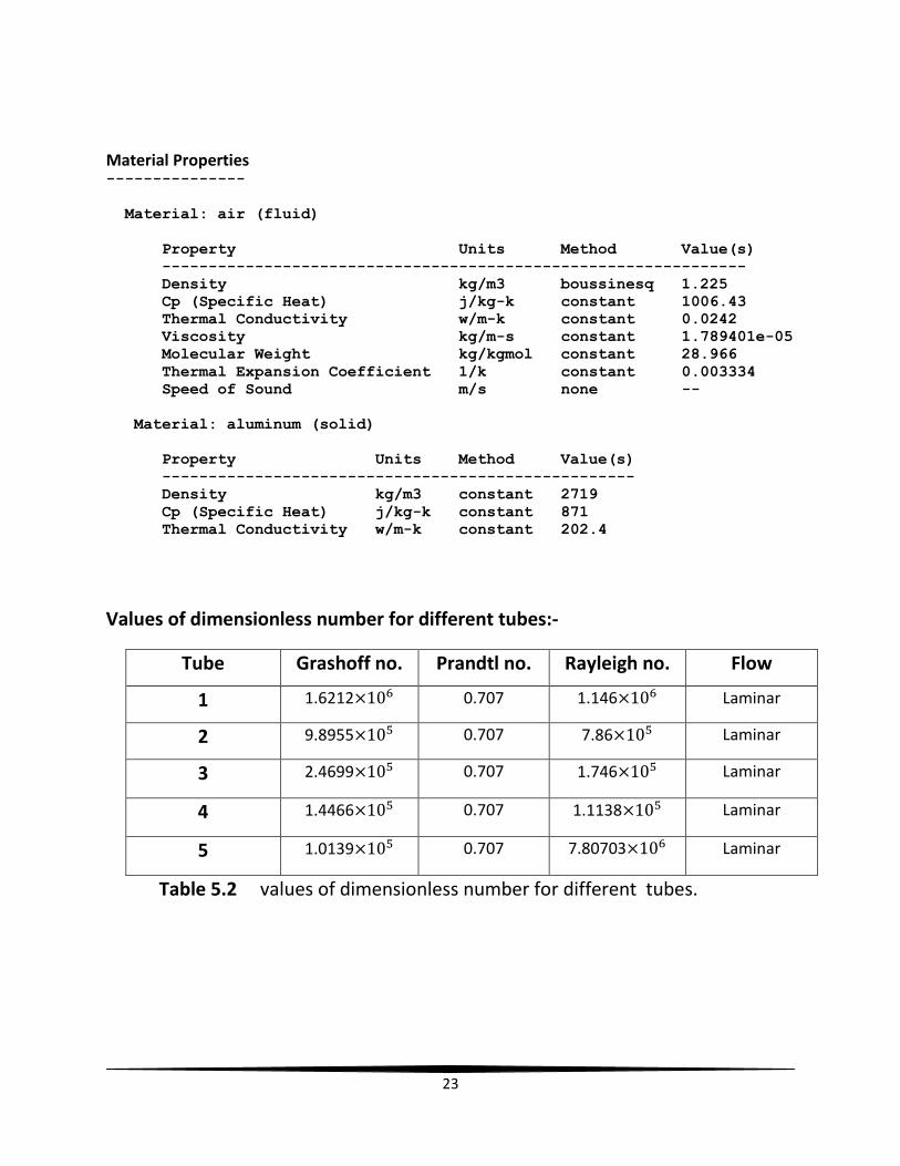
Material Properties ---------------
Material: air (fluid)
Property Units Method Value(s)
---------------------------------------------------------------
Density kg/m3 boussinesq 1.225
Cp (Specific Heat) j/kg-k constant 1006.43
Thermal Conductivity w/m-k constant 0.0242
Viscosity kg/m-s constant 1.789401e-05
Molecular Weight kg/kgmol constant 28.966
Thermal Expansion Coefficient 1/k constant 0.003334
Speed of Sound m/s none --
Material: aluminum (solid)
Property Units Method Value(s)
---------------------------------------------------
Density kg/m3 constant 2719
Cp (Specific Heat) j/kg-k constant 871
Thermal Conductivity w/m-k constant 202.4
Values of dimensionless number for different tubes:-
Tube Grashoff no. Prandtl no. Rayleigh no. Flow
1 1.6212× 0.707 1.146× Laminar
2 9.8955× 0.707 7.86× Laminar
3 2.4699× 0.707 1.746× Laminar
4 1.4466× 0.707 1.1138× Laminar
5 1.0139× 0.707 7.80703× Laminar
Table 5.2 values of dimensionless number for different tubes.
24
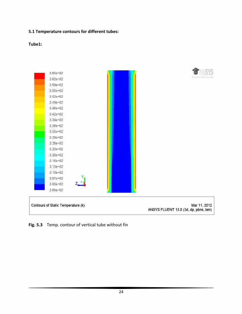
5.1 Temperature contours for different tubes:
Tube1:
Fig. 5.3 Temp. contour of vertical tube without fin
25
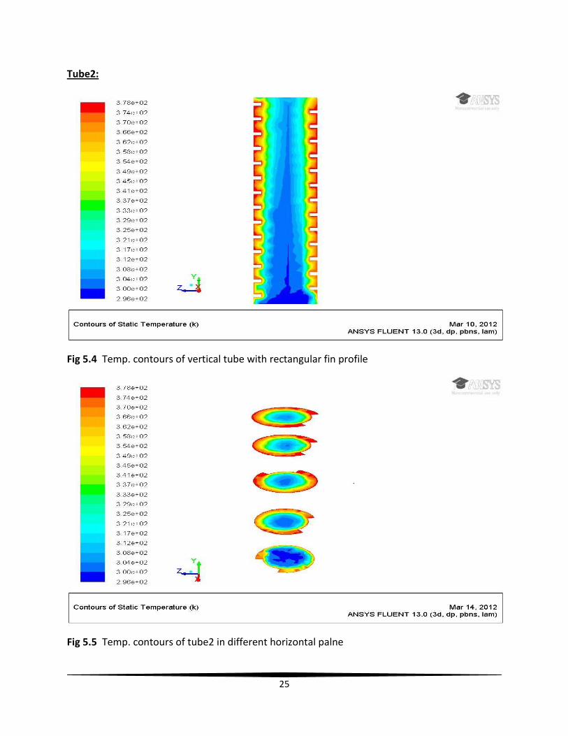
Tube2:
Fig 5.4 Temp. contours of vertical tube with rectangular fin profile
Fig 5.5 Temp. contours of tube2 in different horizontal palne
26
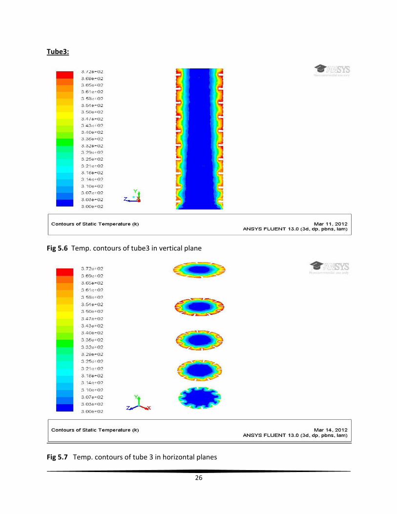
Tube3:
Fig 5.6 Temp. contours of tube3 in vertical plane
Fig 5.7 Temp. contours of tube 3 in horizontal planes
27
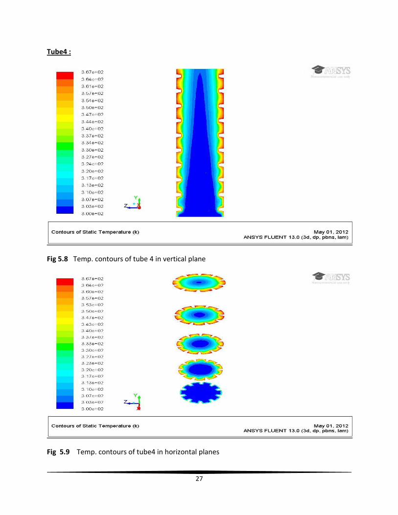
Tube4 :
Fig 5.8 Temp. contours of tube 4 in vertical plane
Fig 5.9 Temp. contours of tube4 in horizontal planes
28
Tube5 :
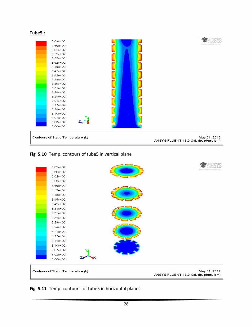
Fig 5.10 Temp. contours of tube5 in vertical plane
Fig 5.11 Temp. contours of tube5 in horizontal planes
29
5.2 Surface Nusselt number:
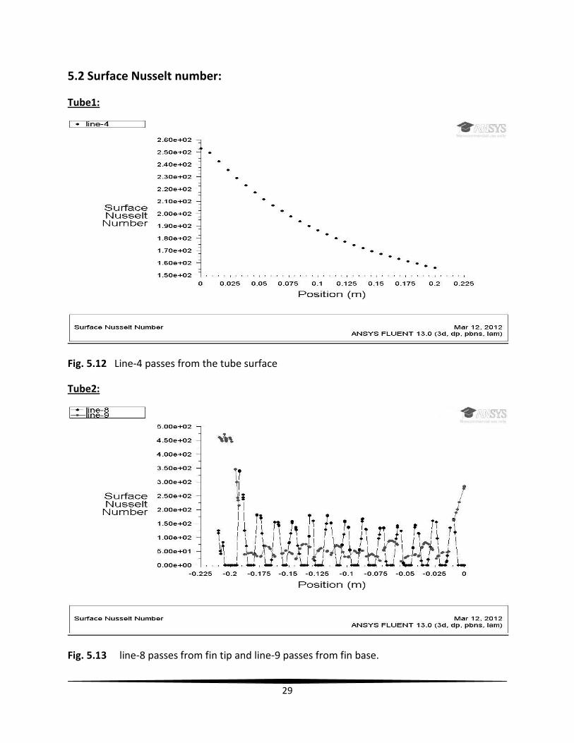
Tube1:
Fig. 5.12 Line-4 passes from the tube surface
Tube2:
Fig. 5.13 line-8 passes from fin tip and line-9 passes from fin base.
30
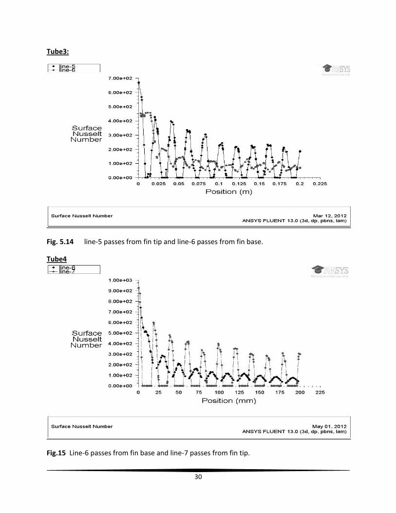
Tube3:
Fig. 5.14 line-5 passes from fin tip and line-6 passes from fin base.
Tube4
Fig.15 Line-6 passes from fin base and line-7 passes from fin tip.
31
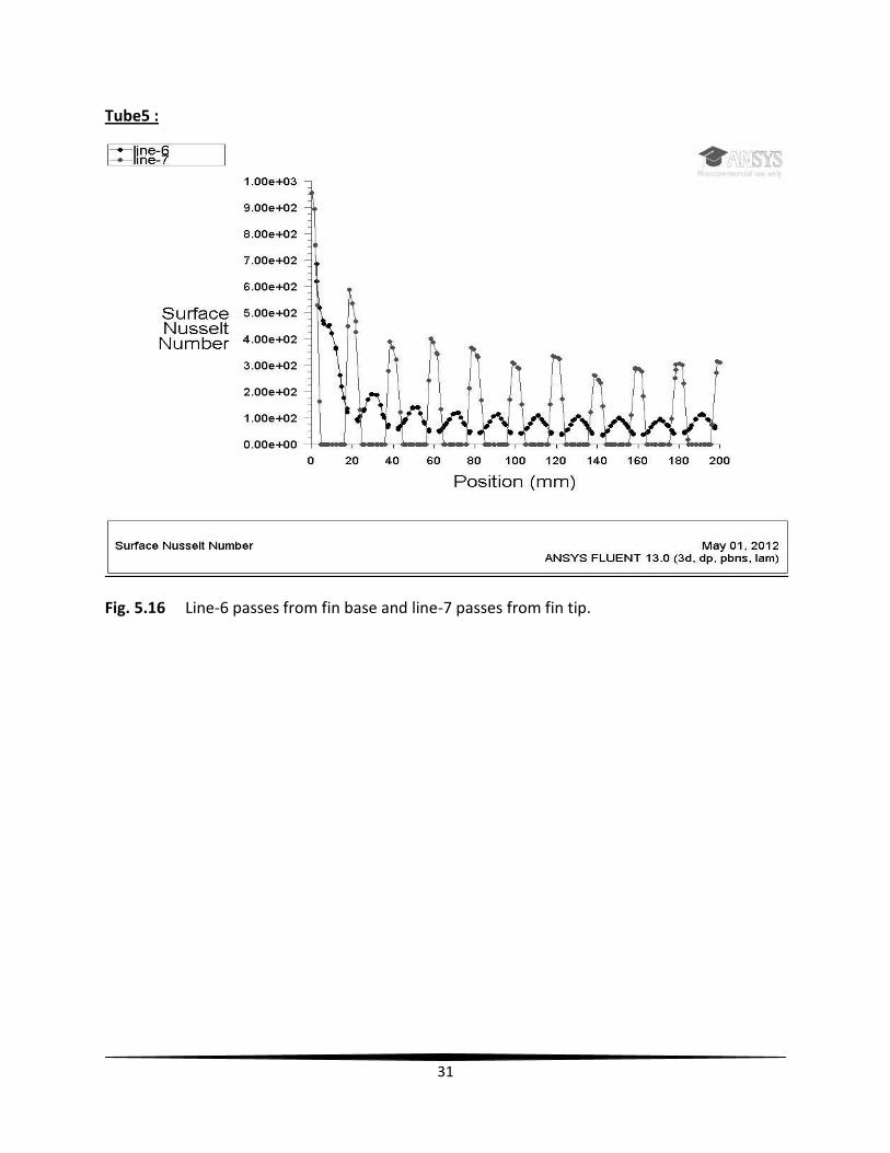
Tube5 :
Fig. 5.16 Line-6 passes from fin base and line-7 passes from fin tip.
32
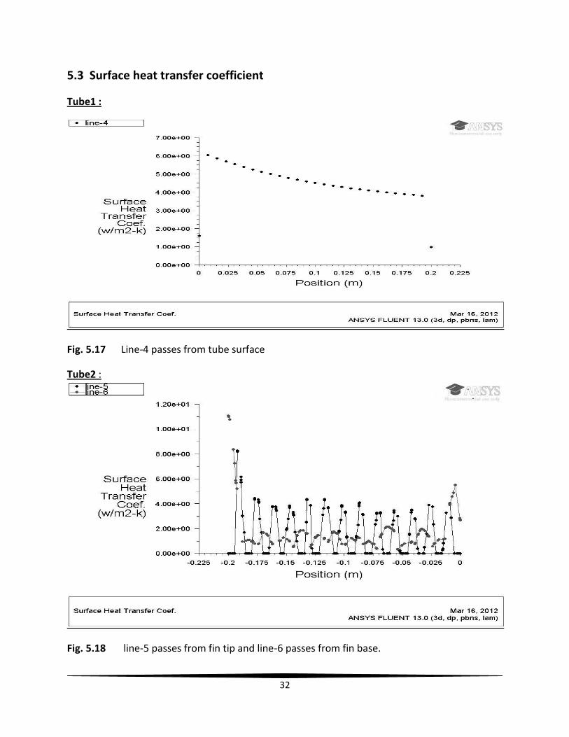
5.3 Surface heat transfer coefficient
Tube1 :
Fig. 5.17 Line-4 passes from tube surface
Tube2 :
Fig. 5.18 line-5 passes from fin tip and line-6 passes from fin base.

33
Tube3 :
Fig. 5.19 line-5 passes from fin base and line-6 passes from fin tip.
Tube4 :
Fig. 5.20 line-6 passes from fin base and line-7 passes from fin tip.

34
Tube5 :
Fig. 5.21 line-6 passes from fin base and line 7 passes from fin tip.
35
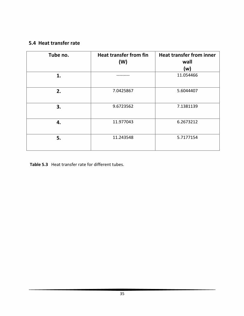
5.4 Heat transfer rate
Tube no. Heat transfer from fin (W)
Heat transfer from inner wall (w)
1. --------- 11.054466
2. 7.0425867 5.6044407
3. 9.6723562 7.1381139
4. 11.977043 6.2673212
5. 11.243548 5.7177154
Table 5.3 Heat transfer rate for different tubes.

36
CHAPTER~6
37
6. Conclusion
1. The tube1, tube2 and tube3 have been compared on the basis of different graphs
governed from the CFD analysis and it has seen that from fig. 5.3, 5.4 and fig. 5.5, fin
configuration in tube3 is more effective than other two tubes. The geometry of fins used
in Tube2 has more restricted path for the air flow which increases the flow resistance
and decreases the air flow rate and that downs the heat transfer rate. From fig. 5.12, fig.
5.13 and fig. 5.14, it can be seen that value of surface nusselt number has maximum
value for tube3 as compared to tube1 and tube2. For tube3, near the bottom point of
the tube, it is more than 300 which is greater than the tube2 which has nearly equal to
250. The surface heat transfer coefficient is compared at different position on the tube,
and has more value for tube3, nearly equal to 9W/ -k at the lowest position of the
tube, as compared to 5.5W/ -k and 4.5W/ -k for the tube1 and tube2 respectively.
Heat transfer rate is 11.05 W, 12.647 W and 16.81 W respectively for the tube1, tube2
and tube3. Tube3 has maximum heat transfer rate. Hence the results showed that, for
tubes having different fin configurations, the tube having ten equally spaced internal
helical fins is more effective as compared to the tube without fin and tube2 which has
one helical fin with large number of turns.
2. Tube3, tube4, tube5 having same fin configuration, which already had been concluded,
have been compared for best fin profile. Tube3, tube4 and tube5 have rectangular,
trapezoidal and concave parabolic fin profiles respectively. From fig. 5.14, fig. 5.15 and
fig. 5.16, it has seen that at the position of 20mm from the bottom point of the tube the
value of surface nusselt number is 450 for tube3, for tube4 it is more than 600 which is
greater than tube5 which has less than 600. The value of surface heat transfer
coefficient has approximately equal values for tube4 and tube5 of approximately equal
to 14W/ -k as compared to tube3 of approximately equal to 10W/ -k. Heat transfer
rate from tube4 is 18.244 W which is more than 17.061 W and 16.81 W for tube5 and
tube3 respectively. Hence the overall performance of the fins and heat transfer rate
from different fin profile has maximum value for trapezoidal fins for natural convection
through internal fins for the given case.
38
References
1. Nag P.K., Heat and mass transfer, New Delhi, TMH, 2010
2. Kayansayan N., Thermal characteristics of fin and tube heat exchanger, Experimental
thermal and fluid science, 1993, Vol. 7, pg. 177-188
3. Rao V.D., Naidu S.V., Rao B.G., Sharma K.V., Heat transfer from a horizontal fin array by
natural convection and radiation, International journal of heat and mass transfer, 2006,
Vol. 49, pg. 3379-3391
4. Yang M.H., Yeh R.H., Hwang J.J., Mixed convective cooling of a fin in a channel,
International journal of heat and mass transfer, 2009, vol. 53, 760-771
5. Sharif N., Bergman T.L., Faghri A., Enhancement of PCM melting in enclosure with
horizontally fixed internal surfaces, International journal of heat and mass transfer,
2011, vol. 54, pg. 4182-4192
6. Myhren J.A., Holmberg S., Improving the thermal performance of ventilation radiator-
the role of internal convective fins, International journal of heat and mass transfer,
2010, vol. 50, pg. 115-123
7. Tijing L.D., Baek B.J., A study on heat transfer enhancement using straight and twisted
internal fins inserts, International journal of heat and mass transfer, 2006, vol.33, pg.
719-726
8. Munoz J., Abanader A., Analysis of helical finned tubes for parabolic through designed
by CFD tools, Applied energy, 2011, vol. 88, pg. 4139-4149
9. Sazali N., Experimental study of natural convection heat transfer in a vertical internally
finned tube, 2009
10. Wang Q., Zeng M., Lin M., Effect of lateral fin profiles on turbulent flow and heat
transfer performance of internally finned tubes, Applied thermal energy, 2009, vol.29,
pg. 3006-3013
39
11. Giri A., Narasimhan G., Murthy M., Combined natural convection heat and mass transfer
from vertical fin arrays, International journal of heat and mass transfer, 2003, vol. 24,
pg. 100-113
12. Papadopoulous P.K., Hatzikonstantinou P.M., Numerical study of laminar fluid flow in a
curved elliptical duct with internal fins, International journal of heat and fluid flow, vol.
29, April 2009, pg. 540-544
13. Andrew J.L., Ramesh N., Chandratilleke T.T., Laminar convective heat transfer rate in a
micro channel with internal longitudinal fins, International journal of thermal sciences,
October 2009, vol. 48, pg. 1908-1913
14. Aziz A., Fang T., Alternative solution for longitudinal fins of rectangular, trapezoidal and
concave parabolic profiles, Energy conversion and management, 2010, vol. 51, pg. 2188-
2194
15. Donalson I.G., Free convection in a vertical tube with linear wall temperature gradient,
1961
16. Stokes G.G., On the effect of the internal friction of fluids or the motion of pendulums,
Transactions of Cambridge Philosophical Society, 1851, vol. 9, page 8
17. Reynolds, Osbrone(1883), An experimental investigation of circumstances which
determine whether the motion of water shall be direct or sinuous and law of resistance
in parallel channels, philosophical transaction of royal society, vol. 174, pg. 935-982
18. Rathore M. M., Kapuno R., Engineering heat transfer, Jones & Bartlett publishers (2012)
19. Venketashan S. P., Heat transfer, Ane books India