Embed Size (px)
Citation preview

Chapter 5
CFD Simulation of Flows in Stirred Tank ReactorsThrough Prediction of Momentum Source
Weidong Huang and Kun Li
Additional information is available at the end of the chapter
http://dx.doi.org/10.5772/51754
1. Introduction
The mixing and agitation of fluid in a stirred tank have raised continuous attention. Startingwith Harvey and Greaves, Computational Fluid Dynamics (CFD) has been applied as a power‐ful tool for investigating the detailed information on the flow in the tank [1-2]. In their work,the impeller boundary condition (IBC) approach has been proposed for the impeller modeling,in which the flow characteristics near the impeller are experimentally measured, and are speci‐fied as the boundary conditions for the whole flow field computation [1-4]. Because it dependson the experimental data, IBC can hardly predict the flow in the stirred tank and its applicabili‐ty is inherently limited. To overcome this drawback, the multiple rotating reference frames ap‐proach (MRF) has been developed, in which the vessel is divided into two parts: the inner zoneusing a rotating frame and the outer zone associated with a stationary frame, for a steady statesimulation. Although it can predict the flow field, the computation result is slightly lack of ac‐curacy and needs a longer time for convergence [5]. Sliding mesh approach (SM) is anotheravailable approach, in which the inner grid is assumed to rotate with the impeller speed, andthe full transient simulations are carried out [6-7]. SM approach gives an improved result, butit suffers from the large computational expense [8]. Moving-deforming grid technique wasproposed by Perng and Murthy [9], in which the grid throughout the vessel moves with the im‐peller and deforms. This approach requires a rigorous grid quality and the computational ex‐penses are even higher than SM [10-11].
Momentum source term approach adds momentum source in the computational cells to rep‐resent the impeller propelling and the real blades are ignored. In the approach, the genera‐tions of the vessel configuration and grids are simpler, and the computational time is shorterand the computational accuracy is higher. However, the determination of the momentumsource depends on experimental data or empirical coefficients presently [12-13]. The ap‐
© 2013 Huang and Li; licensee InTech. This is an open access article distributed under the terms of theCreative Commons Attribution License (http://creativecommons.org/licenses/by/3.0), which permitsunrestricted use, distribution, and reproduction in any medium, provided the original work is properly cited.

proach proposed by Pericleous and Patel is based on the airfoil aerodynamics and originallyaimed at the two-dimensional flow in the stirred vessels. Xu, McGrath [14] and Patwardhan[15] applied this approach to simulate the three-dimensional flow pattern in a tank with thepitched blade turbines. Revstedt et al. [16] modified the approach for the three-dimensionalsimulation in a Rushton turbine stirred vessel. In their approach, the determination of themomentum source depends on the specified power number. Dhainaut et al. [13] reported akind of momentum source term approach in which the fluid velocity is linearly proportionalto the radius with an empirical coefficient. In our previous study, we proposed to calculatethe momentum source term according to the ideal propeller equation [17], which is relatedto the rotation speed and radius of the blade [18-20], however, the prediction accuracy is justa little better than MRF method.
Besides, other methods, such as inner-outer approach, snapshot approach and adaptiveforce field technique, have been developed, but are less applied[1, 21].
In this study, an equation is proposed to calculate the momentum source term after consid‐ering both impeller propelling force and the radial friction effect between the blades and flu‐id. The flow field in the Rushton turbine stirred vessel was simulated with the CFD model.The available experimental data near the impeller tip and in the bulk region were applied tovalidate this approach. Moreover, the comparisons of the computational accuracy and timewith MRF and SM were carried out.
2. Model and methods
2.1. Stirred tank and grid generation
Fig.1 shows the geometry of the investigated standard six-bladed Rushton turbine stirredtank with four equally spaced baffles. The diameter of cylindrical vessel T = 0.30 m, the di‐ameter of rotating shaft d = 0.012 m, the hub diameter b = 0.020 mm, and the detailed sizeproportions are listed in Table 1. The working fluid is water with density ρ = 998.2 kg m-3
and viscosity μ = 1.003×10⁻³ Pa s. The rotational speed of the impeller N = 250 rpm, leading toa tip speed u tip = 1.31 m s-1 and Reynolds number Re = 41,467 (Re = ρND 2 /μ). Eight axiallocations in the bulk region are also shown in Fig.1. They are the same as the experimentalstudy of Murthy and Joshi [22],
It is well known that sufficiently fine grids and lower-dissipation discretization schemes cansignificantly reduce the numerical errors [23]. And the grid resolution on the blades has animportant influence on capturing the details of flow near the impeller [23-24]. Grid inde‐pendence study has been carried out for momentum source term approach with the stand‐ard k-ε model with different grid resolutions. In this paper, the results of the grid resolutionof 1,429,798 hexahedral cells (r×θ×z ≈ 88×120×131) with the impeller blade covered with96000 cells (r×θ×z = 32×120×25) have been reported for the simulations of standard k-ε modeland Reynolds stress model (RSM). In the region encompassing the impeller dischargestream, contained within 1.5 blade heights above and below the impeller and extending hor‐
Nuclear Reactor Thermal Hydraulics and Other Applications136
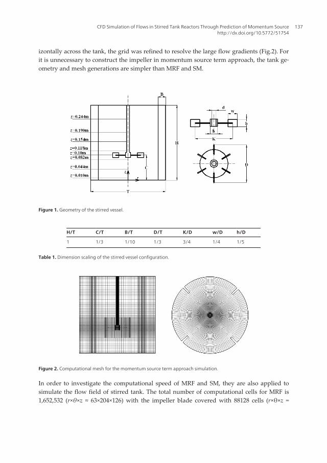
izontally across the tank, the grid was refined to resolve the large flow gradients (Fig.2). Forit is unnecessary to construct the impeller in momentum source term approach, the tank ge‐ometry and mesh generations are simpler than MRF and SM.
Figure 1. Geometry of the stirred vessel.
H/T C/T B/T D/T K/D w/D h/D
1 1/3 1/10 1/3 3/4 1/4 1/5
Table 1. Dimension scaling of the stirred vessel configuration.
Figure 2. Computational mesh for the momentum source term approach simulation.
In order to investigate the computational speed of MRF and SM, they are also applied tosimulate the flow field of stirred tank. The total number of computational cells for MRF is1,652,532 (r×θ×z ≈ 63×204×126) with the impeller blade covered with 88128 cells (r×θ×z =
CFD Simulation of Flows in Stirred Tank Reactors Through Prediction of Momentum Sourcehttp://dx.doi.org/10.5772/51754
137

24×204×18), and for SM is 606,876 (r×θ×z ≈ 60×106×90) with the impeller blade covered with33920 cells (r×θ×z = 20×106×16).
2.2. Momentum source model and control equations
Following the assumptions of Euler equation for turbomachinery [25], the momentumsource term from the driving of blade is determined as following. For a small area of bladedS, assuming that a force exerted by the impeller on the fluid is perpendicular to the bladesurface [14], the propelling force from the impeller dF is considered to be equal to the prod‐uct of the mass flow rate across the interaction section dQ and the fluid velocity variationalong the normal direction of the area element dS:
d dF Q u®
= ×D (1)
Since the rigid body rotational motion of the blade is considered, it is a reasonable as‐sumption that the fluid velocity after being acted on is the same as the velocity of the im‐peller blade, thus Δu can be obtained. For the present study on the vertical blade, Eq.(1)can be written as:
d d ( )F S u u vqr= × × × - (2)
where u is linear velocity of the area element on the blade surface dS, v θ is fluid tangentialvelocity rotating with the impeller before the fluid was propelled by impeller, dS is cross-section area of the interface between fluid and the impeller blade. A similar equation hasbeen applied to describe the propelling effect of the ship’s impeller [26] which we applied itto calculate the momentum source term [18-19].
Furthermore, the fluid is continuously impelled out from the impeller region, so there is a rela‐tive motion of the fluid along the radial direction of the blade. In order to consider the frictioneffect on the fluid movement, the friction resistance equation about the finite flat plate based onthe boundary layer theory is introduced to calculate the friction force approximately [27]:
21d d2 r ff v C Sr= × × (3)
where f is friction force in the computational cells; v r is radial velocity of the fluid; C f is localresistance coefficient related to Rex, which is calculated approximately by:
0.5
5
0.664 Re
Re 5 10f x
x
C -= ×
<= ´(4)
Nuclear Reactor Thermal Hydraulics and Other Applications138

0.2
5 7
0.0577 Re
5 10 Re 1 10f x
x
C -= ×
´ < < ´(5)
where Rex = ρv r x/μ , x is distance between cell center and the center of rotation axis. Inthis paper, we mainly consider the radial friction resistance, ignoring the axial effect forsimplicity. Adding the momentum sources of the both direction into the computationalcells, the real blade is replaced.
In the previous study, the difference between the ensemble-averaged flow field calculatedwith the steady-state and the time-dependent approaches was found to be negligible [28-30].Here, the continuity and momentum equations of motion for three-dimensional incompres‐sible flow, as well as the standard k–ε turbulence equation [31] or Reynolds stress transportequations [32], were solved to calculate single phase flow of the stirred vessel.
The free surface was treated as a flat and rigid lid, so a slip wall was given to the surface.The disc, hub and shaft of the Rushton turbine are specified as moving walls. A standardwall function was given to the other solid walls, including the bottom surface, the sidewalland baffles. Second order upwind discretization scheme was adopted for pressure interpola‐tion and the convection term of momentum, turbulent kinetic energy and energy dissipationrate equations, and the discretized equations were solved iteratively by using the SIMPLEalgorithm for pressure-velocity coupling.
2.3. Power number prediction
The power number N P is an important parameter of the stirred tank, which is generally ap‐plied to validate the CFD predictions [33-34]. One method for calculating the power number isbased on the energy balance, in which the power number of the impeller is calculated from theintegration of the turbulent energy dissipation rate (ε) predicted from the CFD model [35]:
2 /2
0 0 03 5
H T
P
rdrd dzN
N D
pre q
r= ò ò ò (6)
In MRF and SM approaches, the power number is usually calculated from the predictedtorque [36]:
3 5
2p
NmMNN Dpr
= (7)
in which m is the number of the blades, M is the torque of each blade.
In the present study, since the force from blade results in the fluid movement, the impellerpower can be calculated from the integration of the momentum source in the impeller re‐
CFD Simulation of Flows in Stirred Tank Reactors Through Prediction of Momentum Sourcehttp://dx.doi.org/10.5772/51754
139

gion [14], which is called integral power based approach, so the power number is calculatedin the following manner in our study:
/2 2 /2
/2 0 /23 5
( 2 ) d d dC h D
C h D wp
F Nr r r zN
N D
p
q p q
r
+
- -×
= ò ò ò (8)
in which F θ is tangential momentum source term.
3. Results and discussion
3.1. Numerical validation of the flow field near the impeller tip
Fig.3 shows the profiles of the predicted and experimental flow data in the impeller region.Fig.3a gives the comparison of the radial velocity. Escudie and Line [37] summarized theprevious experimental works and found due to the differences of the experimental techni‐que and the stirred-vessel configuration, there existed some inconsistencies among the re‐ported results, whereas the maximum of radial velocity was in the range of 0.7-0.87u tip.
Their experiment study gave a maximal radial velocity of 0.80u tip, while Wu and Patterson[38] 0.75u tip. In present work, momentum source term approach with standard k-ε and RSMpredicts a maximum radial velocity of 0.79u tip and 0.75u tip, respectively, which means thatmomentum source term approach predicts the maximal radial velocity rather well. From fig.3a, the distribution of radial velocity predictions based on momentum source term approachagrees rather well with the experimental data, which outperforms MRF predictions.
With regard to tangential velocity, the maxima from Wu and Patterson [38], and Escudieand Line [37] are 0.66u tip and 0.72u tip respectively. For momentum source term approachwith standard k-ε and RSM, both gave a maximum of 0.63u tip. From Fig. 3b, it can be foundthat the calculated results of momentum source term approach are in good agreement withthe two sets of experimental data, better than MRF predictions.
Fig.3c shows the comparison of axial velocity. The measured results from Wu and Patterson[38], Escudie and Line [37] are almost the same. The momentum source term approach re‐sults match the measured data well in most regions, but predicting the change from themaximum to minimum with several deviations. Compared to standard k-ε model, RSM pre‐dictions of momentum source term approach make some improvements, while MRF predic‐tions are not provided.
In fig.3d, it can be observed that there are two maxima of different magnitudes in the pro‐files of turbulent kinetic energy, thus the curve is not symmetrical. RSM simulations of mo‐mentum source term approach are in accordance with those of standard k-ε model.Momentum source term approach and MRF both successfully predict the variations be‐tween two maxima, but momentum source term approach exhibits a better prediction of theturbulent kinetic energy than MRF.
Nuclear Reactor Thermal Hydraulics and Other Applications140

Figure 3. Comparison of the results predicted by different impeller approaches and experimental data around impel‐ler tip (a) radial velocity, (b) tangential velocity, (c) axial velocity and (d) turbulence kinetic energy: ○ experimental da‐ta (Escudie and Line, 2003), experimental data (Wu and Patterson, 1989), standard k-ε momentum source termapproach predictions, RSM momentum source term approach predictions, MRF predictions (Deglon and Meyer, 2006)
3.2. Numerical validation of the flow field in the bulk region
Fig.4 shows the radial profiles of the mean axial velocity at various axial levels. Here, z<0.10m is in the lower parts of the tank, while z>0.10 m is in the upper parts. It can be noted thatcurve changes in two parts are just opposite, indicating that axial velocity directions are op‐posite. The result shows that the predictions of momentum source term approach withstandard k-ε model and RSM are both in favorable agreement with the experimental data,similar to the predicted results of SM.
Fig.5 depicts the comparison of predicted and experimental radial velocity component. Thehigh speed impeller discharge streams radially. Radial velocity initially increases and thendecreases, attaining the maximum at r/R = 0.6-0.8 near blade. It can be seen that compared tothe experimental data, both the standard k-ε model predictions of momentum source termapproach and SM exhibit some disparity, particularly at the levels in the upper part. At thetop axial levels (z = 0.154 m and z = 0.244 m), there are the largest differences between thepredictions of momentum source term approach and SM, while they have similar accuracyin other positions. However, the results of momentum source term approach and SM pre‐dicted with RSM are consistent with the experimental data.
CFD Simulation of Flows in Stirred Tank Reactors Through Prediction of Momentum Sourcehttp://dx.doi.org/10.5772/51754
141

Figure 4. Comparison of the results predicted by different impeller approaches and experimental data of the dimen‐sionless mean axial velocity in the bulk region: experimental data [39] (Murthy and Joshi, 2008) standard k-ε momen‐tum source term approach predictions, RSM momentum source term approach predictions, standard k-ε SMpredictions (Murthy and Joshi, 2008), RSM SM predictions (Murthy and Joshi, 2008).
Nuclear Reactor Thermal Hydraulics and Other Applications142

Figure 5. Comparison of the results predicted by different impeller approaches and experimental data of the dimen‐sionless mean radial velocity in the bulk region: experimental data (Murthy and Joshi, 2008) standard k-ε momentumsource term approach predictions, RSM momentum source term approach predictions, standard k-ε SM predictions(Murthy and Joshi, 2008), RSM SM predictions (Murthy and Joshi, 2008).
CFD Simulation of Flows in Stirred Tank Reactors Through Prediction of Momentum Sourcehttp://dx.doi.org/10.5772/51754
143

Figure 6. Comparison of the results predicted by different impeller approaches and experimental data of the dimen‐sionless mean tangential velocity in the bulk region: experimental data (Murthy and Joshi, 2008) standard k-ε momen‐tum source term approach predictions, RSM momentum source term approach predictions, standard k-ε SMpredictions (Murthy and Joshi, 2008), RSM SM predictions (Murthy and Joshi, 2008).
Fig.6 illustrates the radial profiles of the tangential velocity component. Yianneskis et al [40]pointed out that the baffles reduce the vessel cross-section, which results in higher valuesfor tangential velocity and a reduced pressure, thus generating reverse flows. It may be thereason that negative velocities exist at the levels of z = 0.01 m and z = 0.044 m. It can be seenthat the computational results of momentum source term approach and SM with standard k-ε model are similar, and both of them predict the reverse flows. They agree rather well withthe experimental data at the lower levels, whereas deviate at the upper levels. For RSM sim‐ulations, the prediction accuracy of two modeling methods have been improved, and theirresults are in good agreement with the experimental results.
Nuclear Reactor Thermal Hydraulics and Other Applications144

Figure 7. Comparison of the results predicted by different impeller approaches and experimental data of the dimen‐sionless mean turbulent kinetic energy in the bulk region: experimental data (Murthy and Joshi, 2008) standard k-εmomentum source term approach predictions, RSM momentum source term approach predictions, standard k-ε SMpredictions (Murthy and Joshi, 2008), RSM SM predictions (Murthy and Joshi, 2008).
Fig.7 shows the numerical comparison of turbulent kinetic energy in various positions. At z= 0.082m, it can be noticed that there are two maxima of turbulent kinetic energy, similar tothe case of tangential velocity (Fig.6). They are generated by the interactions between fluidand blades a, fluid and wall, respectively. Overall, the CFD results which predicted bystandard k-ε model are not satisfying, significantly underpredicting the turbulent kinetic en‐ergy at almost all positions. However, the results of momentum source term approach andSM are similar. Although RSM predictions of momentum source term approach and SMhave reduced the errors, both still underestimate turbulent kinetic energy, and their results
CFD Simulation of Flows in Stirred Tank Reactors Through Prediction of Momentum Sourcehttp://dx.doi.org/10.5772/51754
145

are similar. Due to unsteady and complex nature of flow characteristics in the impeller re‐gion and the continuous conversion of kinetic energy [37], the k-ε model and RSM both failto capture the transfer details of kinetic energy, so the momentum source term approachand SM model underpredict the turbulent kinetic energy with similar deviations when thek-ε and RSM turbulent model are applied.
From the comparisons above, it can be found that predictions of momentum source term ap‐proach with RSM turbulent model are in good agreement with the experimental data as wellas SM model, although both SM and our model have some deviations in prediction of theupper part for the radial and tangential velocity. The models combined with k-ε turbulentmodel have less prediction accuracy, Murthy and Joshi [22] attributed these numerical er‐rors to the overestimation of the eddy viscosity of the k-ε model. It is suggested that thestandard k−ε model performs well when the flow is unidirectional that is with less swirl andweak recirculation [11, 22].
3.3. Velocity vectors
Fig.8 shows velocity vectors of the vertical plane in the middle of two baffles. It can be seenthat after exerting on the momentum source, fluid velocity in the impeller region is veryhigh, and flow gradients are large.
Figure 8. Velocity vectors of stirred tank in the middle plane.
As the high speed fluid jets outward, initially almost not affected by the surrounding fluid, thevelocity contours are dense. The flow impinges on the tank wall, splits up into two parts andchanges the direction. The split water flows at last return to impeller region and accelerated
Nuclear Reactor Thermal Hydraulics and Other Applications146

again, repeating above-mentioned process which generates two circulation loops of differentdirections in the upper and lower part of the tank, respectively. It can be observed that the cir‐culation loop ranges above the z/T value of 0.9, which is consistent with the simulations by Nget al. [24] (1998) (Re = 40,000) and Yapici et al. [41] (2008) (Re = 60,236). Reynolds numbers ofprevious and present studies can ensure that the flow in a stirred vessel is fully developed tur‐bulence, so the circulation pattern predictions can be considered properly.
Fig.9 shows the flow field of stirred tank near the impeller tip. It can be noticed that velocitydistributions are not symmetrical about the impeller centre plate (z = 0.1 m), but shift up‐wards slightly. This result is in agreement with the previous experimental works, that theimpeller is not symmetrically located, the top of the tank is a free surface, and the hub ispresent on the top side of the impeller [38, 42-43]. In this study, this detail has been success‐fully captured in the velocity field near impeller tip, further indicating that momentumsource term approach prediction is in good agreement with experimental results.
Figure 9. Velocity vectors in the middle plane near impeller tip.
3.4. Comparison of power numbers
Table 2 shows the comparison of predicted power numbers with the experimental value.Here, the experimental power numbers reported by Rushton et al. [44-45], Murthy and Joshi[22] are applied in the reference. The quantities obtained by SM model through integral εbased approach are considerably lower than the reported experimental results. Similar re‐sults have been observed in earlier studies [29, 46-47]. These deviations are usually attribut‐ed to underestimation of the turbulent quantities associated to the k–ε model [46, 48]. Thepower number predictions of integral power based approach in the momentum source termapproach with standard k–ε model and RSM are 5.72 and 5.64, respectively, both betweenthe experimental data 5.1 and 6.07, so they are better than those of SM.
Fig.10 shows a log-log plot of the experimentally obtained and predicted power numbers fornine kinds of Reynolds numbers which cover laminar and turbulent flow regimes. It can be ob‐served that at lower Reynolds numbers the power numbers predicted by momentum sourceterm approach are in good agreement with the experimental data of Rushton et al. [44].
CFD Simulation of Flows in Stirred Tank Reactors Through Prediction of Momentum Sourcehttp://dx.doi.org/10.5772/51754
147

Methods N P Error/%
Experimental value (Rushton et al., 1950) 6.07 /
Experimental value (Murthy and Joshi, 2008) 5.1 /
SM torque based approach (Murthy and Joshi, 2008) 4.9 12.26
SM integral ε based approach (Murthy and Joshi, 2008) 3.9 30.17
MRF torque based approach (Deglon and Meyer, 2006) 5.40 3.31
Standard k-ε integral power based approach 5.72 2.42
RSM integral power based approach 5.64 0.98
Table 2. Power number predictions for different approaches at Re=41,467.
Figure 10. Comparison of experimental and predicted power numbers.
3.5. Computational speed
The simulations were carried out on a 100 node AMD64 cluster, each node including 2 four-core processors with 2.26 GHz clock speed and 2 GB memory. 80 processors were applied inall the computations. Present study compared the computational speeds of momentumsource term approach, MRF and SM, and the required expenses are shown in Table 3. It canbe seen that momentum source term approach and MRF using steady state simulations needless computational requirements than SM, and the computational time of momentum sourceterm approach is the least.
Approach Momentum source term MRF SM
Standard k-ε 48 72 340
RSM 60 86 410
Table 3. Comparison of the computational time required by different approaches, h.
Nuclear Reactor Thermal Hydraulics and Other Applications148

4. Conclusions
An equation to predict the momentum source term is proposed without the help of experimen‐tal data in the paper. So the momentum source term approach for CFD prediction of the impel‐ler propelling action has been developed as a tool with predictive capacity. The predictionresults of the approach have been compared with the experimental data, MRF and SM modelpredictions in the literatures. The following conclusions can be drawn from the present work:
1. For the plate blade of the Rushton turbine stirred vessel, the tangential momentumsource added by blade is proposed to be calculated by:
in which u is the linear velocity of the area element on the blade surface dS; v θ is the flu‐id tangential velocity rotating with the impeller before the fluid was propelled by impel‐ler; dS is cross-section area of the interface between fluid and the impeller blade. Theradial friction force of the impeller blade is proposed to be calculated approximately(Wang et al., 2002) as following:
In which f is the friction force in the computational cells, v r is the radial velocity of the fluid.
2. The numerical comparisons of flow field show that the momentum source term ap‐proach predictions are in good agreement with the experimental data. It has been alsofound that the prediction accuracy of momentum source term approach is better thanMRF and similar to SM, whereas the computational time of momentum source term ap‐proach is the least of the three.
Acknowledgements
This work is supported by the Ministry of Science and Technology of the People’s Republicof China (grants No. 2006BAC19B02). The authors would like to thank professor TaohongYe for helpful discussion, the supercomputing center of University of Science and Technolo‐gy of China for their help in computing.
Author details
Weidong Huang* and Kun Li
*Address all correspondence to: [email protected]
Department of Geochemistry and Environmental Science, University of Science and Tech‐nology of China, P. R. China
CFD Simulation of Flows in Stirred Tank Reactors Through Prediction of Momentum Sourcehttp://dx.doi.org/10.5772/51754
149

References
[1] Harvey, P. S., & Greaves, M. (1982). Turbulent-Flow in an Agitated Vessel.1. A Pre‐dictive Model. Transactions of the Institution of Chemical Engineers, 60(4), 195-200.
[2] Harvey, P. S., & Greaves, M. (1982). Turbulent-Flow in an Agitated Vessel.2. Numeri‐cal-Solution and Model Predictions. Transactions of the Institution of Chemical Engi‐neers, 60(4), 201-210.
[3] Ranade, V. V., & Joshi, J. B. (1990). Flow generated by a disc turbine Part II: mathe‐matical modelling and comparison with experimental data. Institution of Chemical En‐gineering [68A], 34-43.
[4] Kresta, S. M., & Wood, P. E. (1991). Prediction of the three-dimensional turbulentflow in stirred tanks. Aiche Journal, 37, 448-460.
[5] Luo, J. Y., Issa, R. I., & Gosman, A. D. (1994). Prediction of impeller-induced flows inmixing vessels using multiple frames of reference. Cambridge, UK. in Proceeding of8th Europe Conference on Mixing, 155-162.
[6] Luo, J. Y., Gosman, A. D., Issa, R. I., et al. (1993). Full Flow-Field Computation ofMixing in Baffled Stirred Vessels. Chemical Engineering Research & Design, 71(A3),342-344.
[7] Murthy, J. Y., Mathur, S. R., & Choudhary, D. (1994). CFD simulation of flows in stir‐red tank rectors using a sliding mesh technique. in Proceeding of 8th Europe Conferenceon Mixing, Cambridge, UK, 155-162.
[8] Mostek, M., Kukukova, A., Jahoda, M., et al. (2005). Comparison of different techni‐ques for modelling of flow field and homogenization in stirred vessels. Chemical Pa‐pers, 59(6A), 380-385.
[9] Perng, C. Y., & Murthy, J. Y. (1994). A moving deforming mesh technique for simula‐tion of flow in mixing tanks. Cambridge, UK. in Proceeding of 8th Europe Conference onMixing, 37-39.
[10] Joshi, J. B., Nere, N. K., Rane, C. V., et al. (2011). Cfd Simulation of Stirred Tanks:Comparison of Turbulence Models. Part II: Axial Flow Impellers, Multiple Impellersand Multiphase Dispersions. Canadian Journal of Chemical Engineering, 89(4), 754-816.
[11] Joshi, J. B., Nere, N. K., Rane, C. V., et al. (2011). Cfd Simulation of Stirred Tanks:Comparison of Turbulence Models. Part I: Radial Flow Impellers. Canadian Journal ofChemical Engineering, 89(1), 23-82.
[12] Pericleous, K. A., & Patel, M. K. (1987). The modelling of tangential and axial agita‐tors in chemical reactors. Physico-chimie Chemical Hydrodynamics, 8, 105-123.
[13] Dhainaut, M., Tetlie, P., & Bech, K. (2005). Modeling and experimental study of a stir‐red tank reactor. International Journal of Chemical Reactor Engineering, 3.
Nuclear Reactor Thermal Hydraulics and Other Applications150

[14] Xu, Y., & Mc Grath, G. (1996). CFD predictions in stirred tank flows. Chemical Engi‐neering Research and Design., 74, 471-475.
[15] Patwardhan, A. W. (2001). Prediction of flow characteristics and energy balance for avariety of downflow impellers. Industrial & Engineering Chemistry Research, 40(17),3806-3816.
[16] Revstedt, J., Fuchs, L., & Tragardh, C. (1998). Large eddy simulations of the turbulentflow in a stirred reactor. Chemical Engineering Science, 53(24), 4041-4053.
[17] Schneekluth, H. (1988). Hydromechanik zum Schiffsentwurf : Vorlesungen. 3., verb. underw. Aufl. ed., Herford: Koehler. ix, 1076.
[18] Jiang, C. Y. (2007). Study of several CFD models in the oxidation ditch system, Universityof Science and Technology of China, Hefei, China.
[19] Jiang, C. Y., Huang, W. D., Wang, G., et al. (2010). Numerical computation of flowfields in an oxidation ditch by computational fluid dynamics model. EnvironmentalScience & Technology, 33, 135-140.
[20] Gou, Q. (2008). Numerical simulation of the propellers in oxidation ditch using Computa‐tional fluid dynamics models in Department of Earth and Space Science, University of Sci‐ence and Technology of China, Hefei.
[21] Li, B., Zhang, Q. W., Hong, H. S., & You, T. (2009). Several factors of CFD numericalsimulation in stirred tank. Chemical Industry and Engineering Progress, 28, 7-12.
[22] Joshi, J. B., & Murthy, B. N. (2008). Assessment of standard k-epsilon, RSM and LESturbulence models in a baffled stirred vessel agitated by various impeller designs.Chemical Engineering Science, 63(22), 5468-5495.
[23] Deglon, D. A., & Meyer, C. J. (2006). CFD modelling of stirred tanks: Numerical con‐siderations. Minerals Engineering, 19(10), 1059-1068.
[24] Ng, K., Fentiman, N. J., Lee, K. C., et al. (1998). Assessment of sliding mesh CFD pre‐dictions and LDA measurements of the flow in a tank stirred by a Rushton impeller.Chemical Engineering Research & Design, 76(A6), 737-747.
[25] Ding, Z. R. (2002). Hydrodynamics, Beijing, China, Higher Education Press.
[26] Schneekluth, H. (1997). Hydromechanik zum schiffsentwurf, Herford, Koehler BookCompany, 3, In Chinese, translated by Xian P.L., Shanghai, China: Publishing com‐pany of Shanghai Jiao Tong University, 1988.
[27] Wang, Y. D., Luo, G. S., & Liu, Q. (2002). Principles of transport processes in chemicalengineering, Beijing, China, Tsinghua University Press.
[28] Wechsler, K., Breuer, M., & Durst, F. (1999). Steady and unsteady computations ofturbulent flows induced by a 4/45 degrees pitched-blade impeller. Journal of FluidsEngineering, 121, 318-329.
CFD Simulation of Flows in Stirred Tank Reactors Through Prediction of Momentum Sourcehttp://dx.doi.org/10.5772/51754
151

[29] Montante, G, Coroneo, M, Paglianti, A, et al. (2011). CFD prediction of fluid flow andmixing in stirred tanks: Numerical issues about the RANS simulations. Computers &Chemical Engineering, 35(10), 1959-1968.
[30] Aubin, J., Fletcher, D. F., & Xuereb, C. (2004). Modeling turbulent flow in stirredtanks with CFD: the influence of the modeling approach, turbulence model and nu‐merical scheme. Experimental Thermal and Fluid Science, 28(5), 431-445.
[31] Launder, B. E., & Spalding, D. B. (1974). Numerical computation of turbulent flows.Computer Methods in Applied Mechanics and Engineering, 3, 269-289.
[32] Speziale, C. G., Sarkar, S., & Gatski, T. B. (1991). Modelling the pressure-strain corre‐lation of turbulence: an invariant dynamical systems approach. Journal of Fluid Me‐chanics, 227, 245-272.
[33] Brucato, A. M. C. F. G., et al. (1998). Numerical prediction of flows in baffled stirredvessels: a comparison of alternative modelling approaches. Chemical Engineering Sci‐ence, 53, 3653-3684.
[34] Bartels, C., Breuer, M., Wechsler, K., et al. (2002). Computational fluid dynamics ap‐plications on parallel-vector computers: computations of stirred vessel flows. Com‐puters & Fluids, 31(1), 69-97.
[35] Xuereb, C., & Bertrand, J. (1996). D hydrodynamics in a tank stirred by a double-pro‐peller system and filled with a liquid having evolving rheological properties. Chemi‐cal Engineering Science, 51(10), 1725-1734.
[36] Shekhar, S. M., & Jayanti, S. (2002). CFD study of power and mixing time for paddlemixing in unbaffled vessels. Chemical Engineering Research & Design, 80(A5), 482-498.
[37] Line, A., & Escudie, R. (2003). Experimental analysis of hydrodynamics in a radiallyagitated tank. Aiche Journal, 49(3), 585-603.
[38] Wu, H, & Patterson, G.K. (1989). Laser-doppler measurements of turbulent flow pa‐rameters in a stirred mixer. Chemical Engineering Science, 44, 2207-2221.
[39] Murthy, B. N., & Joshi, J. B. (2008). Assessment of standard k-ε, RSM and LES turbu‐lence models in a baffled stirred vessel agitated by various impeller designs. ChemicalEngineering Science, 63, 5468-5495.
[40] Yianneskis, M., Popiolek, Z., & Whitelaw, J. H. (1987). An experimental study of thesteady and unsteady flow characteristics of stirred reactors. Journal of Fluid mechanics,175, 537-555.
[41] Yapici, K., Karasozen, B., Schafer, M., et al. (2008). Numerical investigation of the ef‐fect of the Rushton type turbine design factors on agitated tank flow characteristics.Chemical Engineering and Processing, 47, 1340-1349.
[42] Stoots, C. M., & Calabresc, R. V. (1995). Mean velocity field relative to a rushton tur‐bine blade. Aiche Journal, 41, 1-11.
Nuclear Reactor Thermal Hydraulics and Other Applications152

[43] Derksen, J. J., Doelman, M. S., & Van den Akker, H. E. A. (1999). Three-dimensionalLDA measurements in the impeller region of a turbulently stirred tank. Experimentsin Fluids, 27(6), 522-532.
[44] Rushton, J. H., Costich, E. W., & Everett, H. J. (1950). Power Characteristics of MixingImpellers.1. Chemical Engineering Progress, 46(8), 395-404.
[45] Rushton, J. H., Costich, E. W., & Everett, H. J. (1950). Power Characteristics of MixingImpellers.2. Chemical Engineering Progress, 46(9), 467-476.
[46] Kukukova, A., Mostek, M., Jahoda, M., et al. (2005). CFD prediction of flow and ho‐mogenization in a stirred vessel: Part I vessel with one and two impellers. ChemicalEngineering & Technology, 28(10), 1125-1133.
[47] Uludag, Y., Yapici, K., Karasozen, B., et al. (2008). Numerical investigation of the ef‐fect of the Rushton type turbine design factors on agitated tank flow characteristics.Chemical Engineering and Processing, 47(8), 1346-1355.
[48] Sommerfeld, M., & Decker, S. (2004). State of the art and future trends in CFD simu‐lation of stirred vessel hydrodynamics. Chemical Engineering & Technology, 27(3),215-224.
CFD Simulation of Flows in Stirred Tank Reactors Through Prediction of Momentum Sourcehttp://dx.doi.org/10.5772/51754
153