Embed Size (px)
Citation preview
CFD with OpenSource software
A course at Chalmers University of TechnologyTaught by Hakan Nilsson
Project work:
The implementation of interFoam solver as a flow model
of the fsiFoam solver for strong fluid-structure interaction
Developed for foam-extend-3.1Requires: Paraview
Author:Thomas Vyzikas
Peer reviewed by:Hakan NilssonJelena Andric
Disclaimer: This is a student project work, done as part of a course where OpenFOAM and someother OpenSource software are introduced to the students. Any reader should be aware that it
might not be free of errors. Still, it might be useful for someone who would like learn some detailssimilar to the ones presented in the report and in the accompanying files. The material has gone
through a review process. The role of the reviewer is to go through the tutorial and make sure thatit works, that it is possible to follow, and to some extent correct the writing. The reviewer has no
responsibility for the contents.
January 22, 2015
Contents
1 Introduction 21.1 Basics of the Fluid-Structure Interaction problem . . . . . . . . . . . . . . . . . . . . 21.2 Scope of the work . . . . . . . . . . . . . . . . . . . . . . . . . . . . . . . . . . . . . . 3
2 The FSI package 52.1 Installation of the FSI package . . . . . . . . . . . . . . . . . . . . . . . . . . . . . . 52.2 Overview of the FSI package . . . . . . . . . . . . . . . . . . . . . . . . . . . . . . . 6
2.2.1 Overview of the fluidStructureInteraction library . . . . . . . . . . . . . . . . 7
3 An insight of the flow models 103.1 The fsiFoam and its connection to the flow models . . . . . . . . . . . . . . . . . . . 103.2 The existing flow models . . . . . . . . . . . . . . . . . . . . . . . . . . . . . . . . . . 12
3.2.1 Description of the existing flow models . . . . . . . . . . . . . . . . . . . . . . 123.2.2 Comparison of the flow models with the corresponding solvers . . . . . . . . . 14
3.3 Running the beamInCrossFlow tutorial with all the existing flow models . . . . . . . 223.3.1 beamInCrossFlow with icoFoam and consistentIcoFlow . . . . . . . . . . . . 223.3.2 beamInCrossFlow with pisoFlow . . . . . . . . . . . . . . . . . . . . . . . . . 25
4 Building and testing interFlow 284.1 Introduction of a new flow model . . . . . . . . . . . . . . . . . . . . . . . . . . . . . 284.2 Introduction of the two phase fluid flow . . . . . . . . . . . . . . . . . . . . . . . . . 29
4.2.1 Comparison of the source code of interDyMFoam and interFlow . . . . . . . 294.2.2 Modifications in the interFlow.C interFlow.H file . . . . . . . . . . . . . . . . 30
4.2.2.1 Modifications in the constructors . . . . . . . . . . . . . . . . . . . . 304.2.2.2 Modifications in the member functions . . . . . . . . . . . . . . . . 34
4.3 Preparation of the interFlow tutorial . . . . . . . . . . . . . . . . . . . . . . . . . . . 374.3.1 Introducing the fields . . . . . . . . . . . . . . . . . . . . . . . . . . . . . . . 374.3.2 Modifications in the boundary conditions . . . . . . . . . . . . . . . . . . . . 384.3.3 Modifications in the constant directory . . . . . . . . . . . . . . . . . . . . . . 404.3.4 Modifications in the system directory . . . . . . . . . . . . . . . . . . . . . . 42
5 Conclusions and future work 48
1
Chapter 1
Introduction
1.1 Basics of the Fluid-Structure Interaction problem
The Fluid-Structure Interaction (FSI) problem is a very commonly faced engineering problem span-ning from aerospace engineering to biomechanics. The approaches that OpenFOAM has incorpo-rated for solving the interaction between the fluid and the structure were presented during the thirdoccasion of the ”CFD with OpenSource software” course by Hua-Dong Yao [3] in 2014.
The idea behind the FSI problem is that the flow deforms an elastic structure, which by deforming in-fluences the flow around it. As a result, FSI is a problem of both fluid mechanics and solid mechanics.
The FSI simulation approaches are discussed in Zeljko Tukovic’s presentation in a previous Open-FOAM course [7]. The methods that can be considered are split in two approaches:
1. The simultaneous or monolithic approach, where the interaction of the fluid and the structureat the mutual interface is treated synchronously, through a unified mathematical model and aunified discretisation method. The system of equations is solved iteratively, which guaranteesunconditional stability. In general, monolithic schemes are accurate and stable, but computa-tionally expensive. The monolithic approach is ideal for strong coupling between the fluid andthe solid.
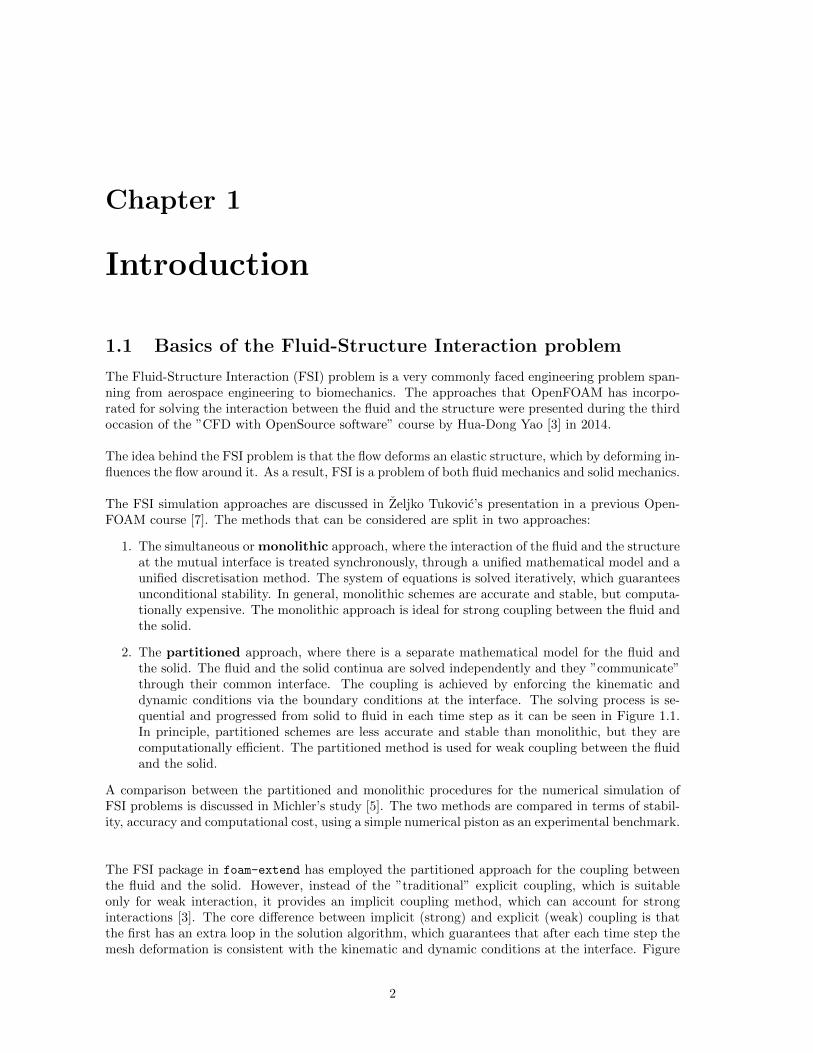
2. The partitioned approach, where there is a separate mathematical model for the fluid andthe solid. The fluid and the solid continua are solved independently and they ”communicate”through their common interface. The coupling is achieved by enforcing the kinematic anddynamic conditions via the boundary conditions at the interface. The solving process is se-quential and progressed from solid to fluid in each time step as it can be seen in Figure 1.1.In principle, partitioned schemes are less accurate and stable than monolithic, but they arecomputationally efficient. The partitioned method is used for weak coupling between the fluidand the solid.
A comparison between the partitioned and monolithic procedures for the numerical simulation ofFSI problems is discussed in Michler’s study [5]. The two methods are compared in terms of stabil-ity, accuracy and computational cost, using a simple numerical piston as an experimental benchmark.
The FSI package in foam-extend has employed the partitioned approach for the coupling betweenthe fluid and the solid. However, instead of the ”traditional” explicit coupling, which is suitableonly for weak interaction, it provides an implicit coupling method, which can account for stronginteractions [3]. The core difference between implicit (strong) and explicit (weak) coupling is thatthe first has an extra loop in the solution algorithm, which guarantees that after each time step themesh deformation is consistent with the kinematic and dynamic conditions at the interface. Figure
2
Structural solver
Fluid mesh motion solver
Fluid solver
Structural mesh update
residual>SMALLStructural solver
Fluid mesh motion solver
Fluid solver
Structural mesh update
Next time step Next time step
Weak coupling Strong couplingPrevious time step Previous time step Previous time step Previous time step
Figure 1.1: FSI solving process with weak and strong coupling using the partitioned approach
1.1 demonstrates the difference between the weak and the strong coupling. The solution strategy ofthe explicit method is analytically described in Hua-Dong Yao’s presentation [3]. It is also importantto underline the use of the Aitken adaptive under-relaxation technique to accelerate the couplingprocess.
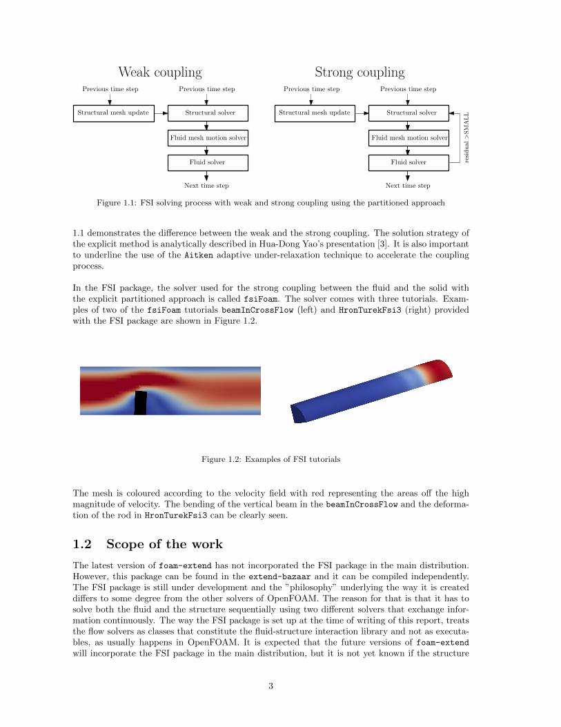
In the FSI package, the solver used for the strong coupling between the fluid and the solid withthe explicit partitioned approach is called fsiFoam. The solver comes with three tutorials. Exam-ples of two of the fsiFoam tutorials beamInCrossFlow (left) and HronTurekFsi3 (right) providedwith the FSI package are shown in Figure 1.2.
Figure 1.2: Examples of FSI tutorials
The mesh is coloured according to the velocity field with red representing the areas off the highmagnitude of velocity. The bending of the vertical beam in the beamInCrossFlow and the deforma-tion of the rod in HronTurekFsi3 can be clearly seen.
1.2 Scope of the work
The latest version of foam-extend has not incorporated the FSI package in the main distribution.However, this package can be found in the extend-bazaar and it can be compiled independently.The FSI package is still under development and the ”philosophy” underlying the way it is createddiffers to some degree from the other solvers of OpenFOAM. The reason for that is that it has tosolve both the fluid and the structure sequentially using two different solvers that exchange infor-mation continuously. The way the FSI package is set up at the time of writing of this report, treatsthe flow solvers as classes that constitute the fluid-structure interaction library and not as executa-bles, as usually happens in OpenFOAM. It is expected that the future versions of foam-extend
will incorporate the FSI package in the main distribution, but it is not yet known if the structure
3
of the package will remain the same or change substantially to conform with the OpenFOAM norms.
The FSI problem has great applications for ocean and coastal engineering. The response of flexiblestructures for coastal protection, wave & tidal energy harnessing and oil industry under the waveimpact is of significant importance for the survivability of these structures. However, none of theexisting flow models in the FSI package allows free surface modelling. This becomes possible withthe inclusion of a two phase flow model in the FSI package. Therefore, this study focuses on theimplementation of a two phase flow solver in the FSI package for foam-extend-3.1.
In this work, the flow solver used as the basis to build a two-phase flow model is interFoam.It is a solver designed for two incompressible, isothermal immiscible fluids using a VOF (volume offluid) phase-fraction based interface capturing approach, allowing for mesh motion (interDyMFoam)and turbulence modelling (i.e. laminar, Reynolds Averaged Simulation (RAS) and Large Eddy Sim-ulation (LES)). The new flow model, namely interFlow, is part of the fluid-structure interactionlibrary and it has similar structure as the existing flow models: icoFlow, consistentIcoFlow andpisoFlow.
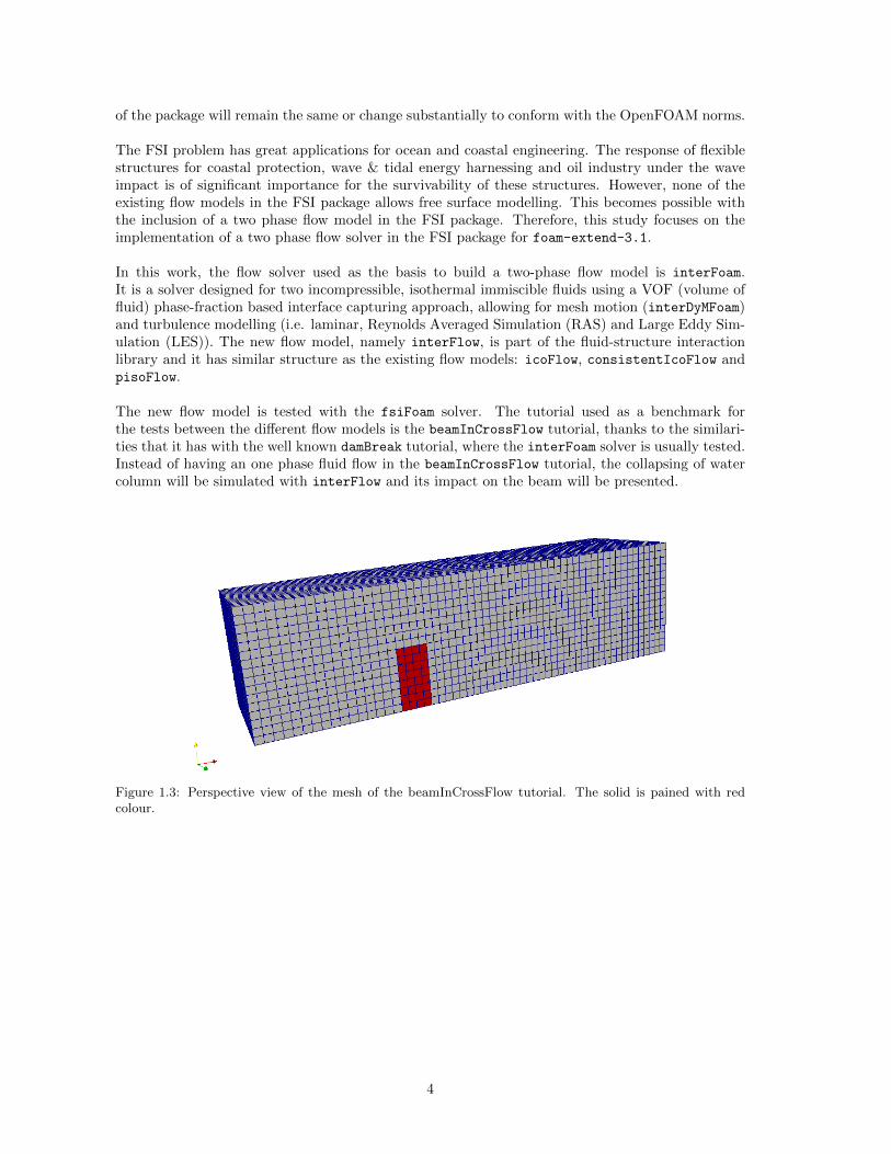
The new flow model is tested with the fsiFoam solver. The tutorial used as a benchmark forthe tests between the different flow models is the beamInCrossFlow tutorial, thanks to the similari-ties that it has with the well known damBreak tutorial, where the interFoam solver is usually tested.Instead of having an one phase fluid flow in the beamInCrossFlow tutorial, the collapsing of watercolumn will be simulated with interFlow and its impact on the beam will be presented.
Figure 1.3: Perspective view of the mesh of the beamInCrossFlow tutorial. The solid is pained with redcolour.
4
Chapter 2
The FSI package
This section begins with the necessary guidelines needed to install the FSI package for foam-extend-3.1 and continues with the overview of the structure of the FSI package.
2.1 Installation of the FSI package
The FSI package can be downloaded independently from http://openfoamwiki.net/index.php/
Extend-bazaar/Toolkits/Fluid-structure_interaction or it can be found in the $WM_PROJECT_DIR/extend-bazaar/FluidStructureInteraction directory.
Provided that foam-extend-3.1 is downloaded and compiled, the user has to compile the FSI pack-age independently. It is recommended to copy the FSI package in the user directory and compile itthere to avoid damaging the central installation of foam, to keep the original package untouched andto avoid messing with permission rights. One can also compile the package at the $WM_PROJECT_DIR
and the libraries and executables will still be created in the user’s directory. To compile FSI in$WM_PROJECT_DIR execute the following commands:
. $HOME/foam/foam-extend-3.1/etc/bashrc
cd $WM_PROJECT_DIR/extend-bazaar
./Allwmake
This basically downloads and compiles the FSI package and cfMesh, which is not necessary. Asstated above, the package can be downloaded from the repository and later unpacked, which isactually what happens when the previous ./Allwmake script is executed. The commands are:
wget http://openfoamwiki.net/images/5/52/Fsi_31.tar.gz
tar zxvf Fsi_31.tar.gz
rm Fsi_31.tar.gz
To compile the FSI package at the user’s directory, copy it and compile it there:
cd $WM_PROJECT_USER_DIR
cp -r $WM_PROJECT_DIR/extend-bazaar/FluidStructureInteraction/ .
Now that the FSI package is copied in the user’s directory, the compilation can be done. Beforestarting, make sure that all the executables will be created in the $(FOAM_USER_APPBIN) and all thelibraries in the $(FOAM_USER_LIBBIN).
To compile the package in the user’s directory execute the following commands:
5
cd $WM_PROJECT_USER_DIR/FluidStructureInteraction/src
chmod 755 *
./Allwclean
./Allwmake
At this point, it is important to mention that the FSI package contains numerous source files thathave the same name with files of the central installation. Some of these files contain significantdifferences and some others are identical. However, not all the files contained in the FSI package arecompiled and some of the corresponding original OpenFOAM files are used, despite the fact thatsome of them contain substantial modifications. Moreover, by looking inside the source files of theFSI package, one can notice that there are many parts commented out. It is expected that a clean-ing up of the FSI packae will take place in the future before it becomes part of the main distribution.
A second point is that there is a chance that one faces problems compiling the fluidStructure
Interaction library. If this library is not created further problems will occur in the compilation.The conflict has to do with the IOReferencer in the constitutiveModel.C. constitutiveModel.Cis also included in the main installation in the $FOAM_SOURCE/solidModels/constitutiveModel/
with a few changes. A rough solution is to use the latter file. There are of course some differences,between the two constitutive models, however, the fsiFoam can still run without using the file fromthe FSI package. This is achieved my commenting out the stressModels/constitutiveModel/
constitutiveModel.C file in the src/fluidStructureInterface/Make/files like that:/*stressModels/constitutiveModel/constitutiveModel.C*/.No further changes are required and the file~/foam /foam-extend-3.1/src/solidModels/constitutiveModel/constitutiveModel.C
is used instead.
2.2 Overview of the FSI package
The FluidStructureInteraction directory contains two subdirectories: run, where all the tu-torials are located, and src, where the source code is found. src contains three directories:fluidStructureInteraction, solvers, and utilities. The compilation of the fluidStructure
Interaction library is prerequisite for the compilation of the solvers and some utilities.
After compiling the FSI package there is a series of solvers, utilities and libraries that are cre-ated. Taking a look at the ./Allwmake script gives a good idea of the result of the compilation.
Allwmake#!/bin/sh
set -x
wmake libso fluidStructureInteraction
wmake solvers/fsiFoam
wmake solvers/weakFsiFoam
wmake solvers/flowFoam
wmake solvers/stressFoam
wmake solvers/crackStressFoam
wmake solvers/thermalStressFoam
wmake utilities/set2dMeshThickness
wmake utilities/decomposePar
wmake utilities/reconstructPar
6
wmake libso utilities/foamCalcFunctions
wmake libso utilities/meshTools
wmake libso utilities/functionObjects/pointHistory
wmake libso utilities/functionObjects/energyHistory
wmake libso utilities/functionObjects/patchAvgTractionHistory
As it can be seen, the solvers fsiFoam, weakFsiFoam, flowFoam, stressFoam, crackStressFoam andthermalStressFoam are created and the utilities set2dMeshThickness, decomposePar, reconstructPar, foamCalcFunctions, meshTools, pointHistory, energyHistory and patchAvgTractionHistory
are compiled.
The result of the compilation of the FSI package is the creation of the executables and librariesin the $FOAM_USER_APPBIN and $FOAM_USER_LIBBIN directories respectively, as listed in Table 2.1.
Table 2.1: Application and libraries created with the FSI package
Applications LibrariescrackStressFoam libenergyHistory.sodecomposeParFsi libfluidStructureInteraction.so
flowFoam libfoamStressCalcFunctions.sofsiFoam libmeshTools.so
reconstructParFsi libpatchAvgTractionHistory.soset2dMeshThickness libpointHistory.so
stressFoamthermalStressFoam
weakFsiFoam
2.2.1 Overview of the fluidStructureInteraction library
As mentioned before, this study focuses on the fsiFoam and the fluidStructureInteraction li-brary. Actually, all the modifications in the source code will take place in the fluidStructureInteraction directory. However, it is strongly recommended not to try to isolate these applicationsand compile them separately from the FSI package, because they are strongly bonded with manyother source files and libraries.
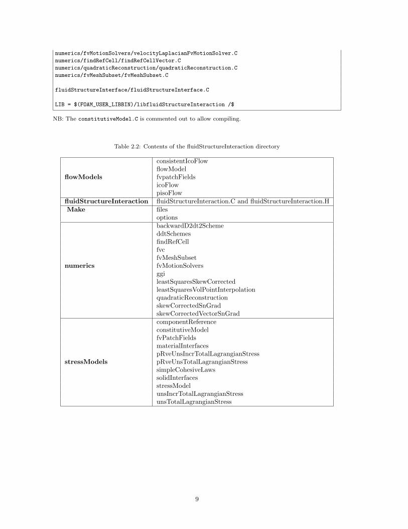
The fluidStructureInteraction directory contains the following directories: flowModels, fluidStructureInterface, numerics and stressModels. The contents of these directories are shownin Table 2.2. It also contains the Make directory, which indicates that it can be compiled using thecommand wmake libso.
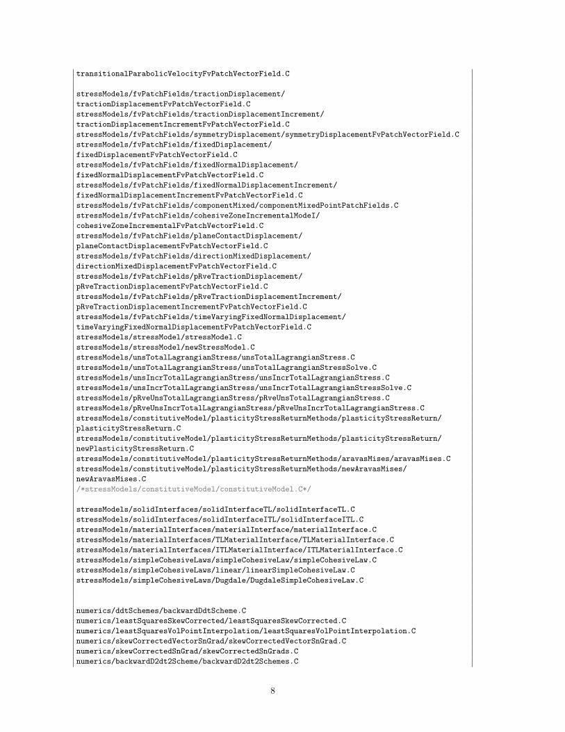
Each of the subdirectories listed in the Table 2.2 contains further subdirectories or source files.It is out of the scope of this document to present the contents in detail and the links between them.However, as it was mentioned before, not all of these files in the FSI package are compiled. There-fore, it is important to know which of these files are actually compiled. For this reason, a look atthe Make/files is useful in order to realise which of them are actually compiled:
fluidStructureInteraction/Make/filesflowModels/flowModel/flowModel.C
flowModels/flowModel/newFlowModel.C
flowModels/icoFlow/icoFlow.C
flowModels/pisoFlow/pisoFlow.C
flowModels/consistentIcoFlow/consistentIcoFlow.C
flowModels/fvPatchFields/extrapolatedPressure/extrapolatedPressureFvPatchScalarField.C
flowModels/fvPatchFields/transitionalParabolicVelocity/
7
transitionalParabolicVelocityFvPatchVectorField.C
stressModels/fvPatchFields/tractionDisplacement/
tractionDisplacementFvPatchVectorField.C
stressModels/fvPatchFields/tractionDisplacementIncrement/
tractionDisplacementIncrementFvPatchVectorField.C
stressModels/fvPatchFields/symmetryDisplacement/symmetryDisplacementFvPatchVectorField.C
stressModels/fvPatchFields/fixedDisplacement/
fixedDisplacementFvPatchVectorField.C
stressModels/fvPatchFields/fixedNormalDisplacement/
fixedNormalDisplacementFvPatchVectorField.C
stressModels/fvPatchFields/fixedNormalDisplacementIncrement/
fixedNormalDisplacementIncrementFvPatchVectorField.C
stressModels/fvPatchFields/componentMixed/componentMixedPointPatchFields.C
stressModels/fvPatchFields/cohesiveZoneIncrementalModeI/
cohesiveZoneIncrementalFvPatchVectorField.C
stressModels/fvPatchFields/planeContactDisplacement/
planeContactDisplacementFvPatchVectorField.C
stressModels/fvPatchFields/directionMixedDisplacement/
directionMixedDisplacementFvPatchVectorField.C
stressModels/fvPatchFields/pRveTractionDisplacement/
pRveTractionDisplacementFvPatchVectorField.C
stressModels/fvPatchFields/pRveTractionDisplacementIncrement/
pRveTractionDisplacementIncrementFvPatchVectorField.C
stressModels/fvPatchFields/timeVaryingFixedNormalDisplacement/
timeVaryingFixedNormalDisplacementFvPatchVectorField.C
stressModels/stressModel/stressModel.C
stressModels/stressModel/newStressModel.C
stressModels/unsTotalLagrangianStress/unsTotalLagrangianStress.C
stressModels/unsTotalLagrangianStress/unsTotalLagrangianStressSolve.C
stressModels/unsIncrTotalLagrangianStress/unsIncrTotalLagrangianStress.C
stressModels/unsIncrTotalLagrangianStress/unsIncrTotalLagrangianStressSolve.C
stressModels/pRveUnsTotalLagrangianStress/pRveUnsTotalLagrangianStress.C
stressModels/pRveUnsIncrTotalLagrangianStress/pRveUnsIncrTotalLagrangianStress.C
stressModels/constitutiveModel/plasticityStressReturnMethods/plasticityStressReturn/
plasticityStressReturn.C
stressModels/constitutiveModel/plasticityStressReturnMethods/plasticityStressReturn/
newPlasticityStressReturn.C
stressModels/constitutiveModel/plasticityStressReturnMethods/aravasMises/aravasMises.C
stressModels/constitutiveModel/plasticityStressReturnMethods/newAravasMises/
newAravasMises.C
/*stressModels/constitutiveModel/constitutiveModel.C*/
stressModels/solidInterfaces/solidInterfaceTL/solidInterfaceTL.C
stressModels/solidInterfaces/solidInterfaceITL/solidInterfaceITL.C
stressModels/materialInterfaces/materialInterface/materialInterface.C
stressModels/materialInterfaces/TLMaterialInterface/TLMaterialInterface.C
stressModels/materialInterfaces/ITLMaterialInterface/ITLMaterialInterface.C
stressModels/simpleCohesiveLaws/simpleCohesiveLaw/simpleCohesiveLaw.C
stressModels/simpleCohesiveLaws/linear/linearSimpleCohesiveLaw.C
stressModels/simpleCohesiveLaws/Dugdale/DugdaleSimpleCohesiveLaw.C
numerics/ddtSchemes/backwardDdtScheme.C
numerics/leastSquaresSkewCorrected/leastSquaresSkewCorrected.C
numerics/leastSquaresVolPointInterpolation/leastSquaresVolPointInterpolation.C
numerics/skewCorrectedVectorSnGrad/skewCorrectedVectorSnGrad.C
numerics/skewCorrectedSnGrad/skewCorrectedSnGrads.C
numerics/backwardD2dt2Scheme/backwardD2dt2Schemes.C
8
numerics/fvMotionSolvers/velocityLaplacianFvMotionSolver.C
numerics/findRefCell/findRefCellVector.C
numerics/quadraticReconstruction/quadraticReconstruction.C
numerics/fvMeshSubset/fvMeshSubset.C
fluidStructureInterface/fluidStructureInterface.C
LIB = $(FOAM_USER_LIBBIN)/libfluidStructureInteraction /$
NB: The constitutiveModel.C is commented out to allow compiling.
Table 2.2: Contents of the fluidStructureInteraction directory
consistentIcoFlowflowModel
flowModels fvpatchFieldsicoFlowpisoFlow
fluidStructureInteraction fluidStructureInteraction.C and fluidStructureInteraction.HMake files
optionsbackwardD2dt2SchemeddtSchemesfindRefCellfvcfvMeshSubset
numerics fvMotionSolversggileastSquaresSkewCorrectedleastSquaresVolPointInterpolationquadraticReconstructionskewCorrectedSnGradskewCorrectedVectorSnGradcomponentReferenceconstitutiveModelfvPatchFieldsmaterialInterfacespRveUnsIncrTotalLagrangianStress
stressModels pRveUnsTotalLagrangianStresssimpleCohesiveLawssolidInterfacesstressModelunsIncrTotalLagrangianStressunsTotalLagrangianStress
9
Chapter 3
An insight of the flow models
3.1 The fsiFoam and its connection to the flow models
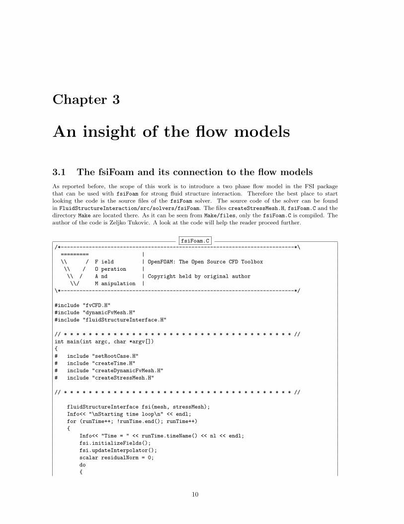
As reported before, the scope of this work is to introduce a two phase flow model in the FSI packagethat can be used with fsiFoam for strong fluid structure interaction. Therefore the best place to startlooking the code is the source files of the fsiFoam solver. The source code of the solver can be foundin FluidStructureInteraction/src/solvers/fsiFoam. The files createStressMesh.H, fsiFoam.C and thedirectory Make are located there. As it can be seen from Make/files, only the fsiFoam.C is compiled. Theauthor of the code is Zeljko Tukovic. A look at the code will help the reader proceed further.
fsiFoam.C/*---------------------------------------------------------------------------*\
========= |
\\ / F ield | OpenFOAM: The Open Source CFD Toolbox
\\ / O peration |
\\ / A nd | Copyright held by original author
\\/ M anipulation |
\*---------------------------------------------------------------------------*/
#include "fvCFD.H"
#include "dynamicFvMesh.H"
#include "fluidStructureInterface.H"
// * * * * * * * * * * * * * * * * * * * * * * * * * * * * * * * * * * * * * //
int main(int argc, char *argv[])
{
# include "setRootCase.H"
# include "createTime.H"
# include "createDynamicFvMesh.H"
# include "createStressMesh.H"
// * * * * * * * * * * * * * * * * * * * * * * * * * * * * * * * * * * * * * //
fluidStructureInterface fsi(mesh, stressMesh);
Info<< "\nStarting time loop\n" << endl;
for (runTime++; !runTime.end(); runTime++)
{
Info<< "Time = " << runTime.timeName() << nl << endl;
fsi.initializeFields();
fsi.updateInterpolator();
scalar residualNorm = 0;
do
{
10
fsi.outerCorr()++;
fsi.updateDisplacement();
fsi.moveFluidMesh();
fsi.flow().evolve();
fsi.updateForce();
fsi.stress().evolve();
residualNorm =
fsi.updateResidual();
}
while
(
(residualNorm > fsi.outerCorrTolerance())
&& (fsi.outerCorr() < fsi.nOuterCorr())
);
fsi.stress().updateTotalFields();
runTime.write();
Info<< "ExecutionTime = " << runTime.elapsedCpuTime() << " s"
<< " ClockTime = " << runTime.elapsedClockTime() << " s"
<< nl << endl;
}
Info<< "End\n" << endl;
return(0);
}
// ************************************************************************* //
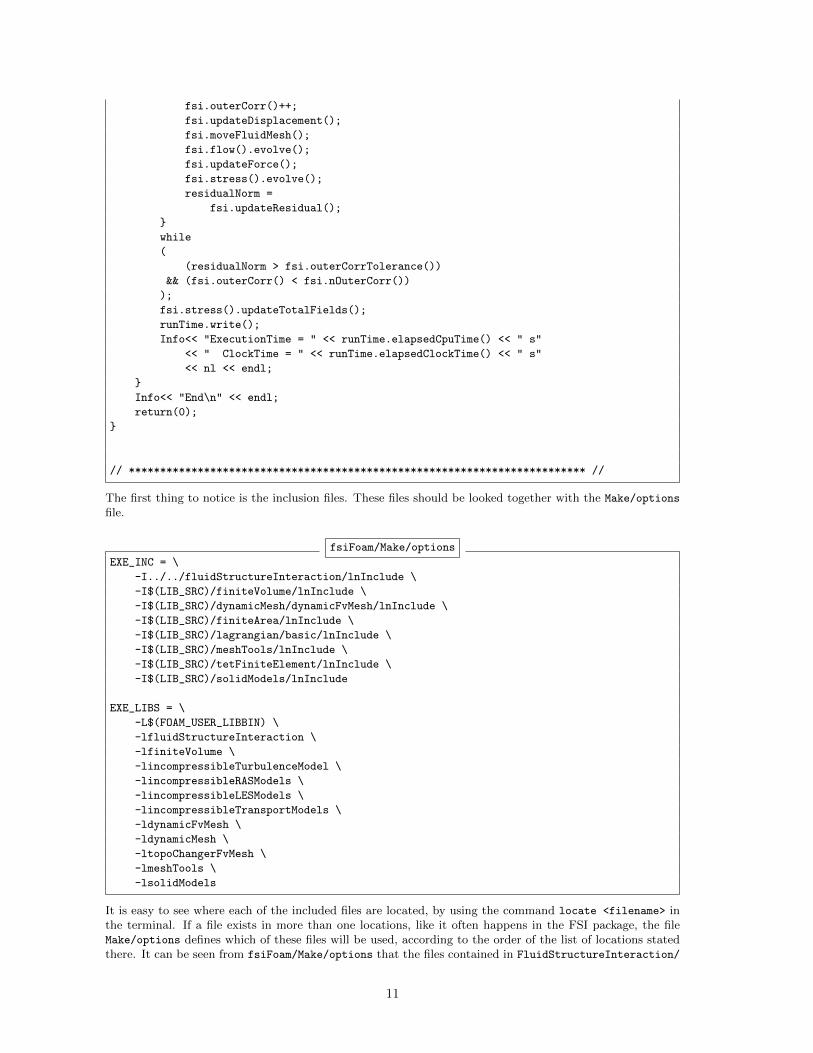
The first thing to notice is the inclusion files. These files should be looked together with the Make/options
file.
fsiFoam/Make/options
EXE_INC = \
-I../../fluidStructureInteraction/lnInclude \
-I$(LIB_SRC)/finiteVolume/lnInclude \
-I$(LIB_SRC)/dynamicMesh/dynamicFvMesh/lnInclude \
-I$(LIB_SRC)/finiteArea/lnInclude \
-I$(LIB_SRC)/lagrangian/basic/lnInclude \
-I$(LIB_SRC)/meshTools/lnInclude \
-I$(LIB_SRC)/tetFiniteElement/lnInclude \
-I$(LIB_SRC)/solidModels/lnInclude
EXE_LIBS = \
-L$(FOAM_USER_LIBBIN) \
-lfluidStructureInteraction \
-lfiniteVolume \
-lincompressibleTurbulenceModel \
-lincompressibleRASModels \
-lincompressibleLESModels \
-lincompressibleTransportModels \
-ldynamicFvMesh \
-ldynamicMesh \
-ltopoChangerFvMesh \
-lmeshTools \
-lsolidModels
It is easy to see where each of the included files are located, by using the command locate <filename> inthe terminal. If a file exists in more than one locations, like it often happens in the FSI package, the fileMake/options defines which of these files will be used, according to the order of the list of locations statedthere. It can be seen from fsiFoam/Make/options that the files contained in FluidStructureInteraction/
11
src/fluidStructureInteraction/lnInclude are taken into account first. The location of the source filesof fsiFoam are shown bellow.
fvCFD.H → $(LIB SRC)/finiteVolume/lnIncludedynamicFvMesh.H → $(LIB SRC)/dynamicMesh/dynamicFvMesh/lnIncludefluidStructureInterface.H → FluidStructureInteraction/src/fluidStructureInteraction/lnIncludesetRootCase.H → $(LIB SRC)/foam/lnIncludecreateDynamicFvMesh.H → $(LIB SRC)/dynamicMesh/dynamicFvMesh/lnIncludecreateStressMesh.H → fsiFoam directory (Header file)
All the other files apart from createStressMesh.H and fluidStructureInterface.H are located in thecentral installation of OpenFOAM. If there are any extra inclusions can only exist in the two files mentioned.createStressMesh.H does not include extra files. The case is not the same for fluidStructureInterface.H.It is useful to take a look at this file and its inclusions. The included files and their locations are listed below.
flowModel.H → /src/fluidStructureInteraction/flowModels/flowModelstressModel.H → /src/fluidStructureInteraction/stressModels/stressModelIOdictionary.H → $(LIB SRC)/foam/lnIncludepatchToPatchInterpolation.H → $(LIB SRC)/foam/lnIncludedynamicFvMesh.H → $(LIB SRC)/dynamicMesh/dynamicFvMesh/lnIncludeggiInterpolation.H → $(LIB SRC)/foam/lnIncludeextendedGgiInterpolation.H → src/fluidStructureInteraction/numerics/ggi/ExtendedGGIInterpolation
NB: The Make/options file for the fluidStructureInterface.H is one level up from the location that it isfound, i.e. in the src/fluidStructureInteraction directory.
As it can be seen, most of the included files in fluidStructureInterface.H belong to the FSI package.If one continues looking into each one of these files, he would realise that they point to other files in theFSI package. Keeping in mind that the scope is to adjust the flow models, the most reasonable step is tofurther look only in the flowModel.H, which is the header file of flowModel.C, and both of them are locatedin /src/fluidStructureInteraction/flowModels/flowModel directory. In this directory, the source filenewFlowModel.C exists, which recognises the available flow models and ensures that the dictionary is notentered twice in the database.
The flowModel.H is used for the declaration of the flowModel class. This file dictates that the dictio-nary flowProperties is read, where the flow model in use is stated. At the end of flowModel.H the memberfunction evolve is defined. At this point, one should return to the fsiFoam.C, where the only reference tothe fluid solver is the fsi.flow().evolve() and realise how the two files are linked.
The connection between the fsiFoam solver and the flow models should be clear:The fsiFoam.C file includes the fluidStructureInterface.H, which includes the flowModel.H.
Now, the question is how a flow model is compiled and becomes available in the FSI package. Goingback to the fluidStructureInteraction/Make/files file, one can see that the flow models are compiledindependently: icoFlow.C, pisoFlow.C etc. The corresponding header files of the flow models (icoFlow.H,pisoFlow.H etc) declare the classes of the flow models. In the declaration the name of each model is defined(icoFlow, pisoFlow etc) which is recognised as a flow model through the flowModel.H.
3.2 The existing flow models
3.2.1 Description of the existing flow models
The available flow models in the FSI package are icoFlow, pisoFlow and consistentIcoFlow. This canbe confirmed by looking at the fluidStructureInteraction/flowModels direcory or by putting a dummyas a flow model in the flowProperties file in the fluid/constant directory of one of the existing tutori-als of the FSI package. Unfortunately, all the flow models lack description at the beginning of the source files.
12
The icoFlow flow model is based on the icoFoam solver, which is a transient solver for incompressible,laminar flow of Newtonian fluids.
The consistentIcoFlow flow model is again based on the icoFoam solver, as it is declared in the consistentIcoFlow.H file. However, there are significant differences between icoFlow.C and consistentIcoFlow.C.This can be easily seen by comparing the source file using the tool kompare. Assuming that the user isin the FluidStructureInteractionsrc/fluidStructureInteraction/flowModels the kompare program isexecuted as follows:
kompare icoFlow/icoFlow.C consistentIcoFlow/consistentIcoFlow.C
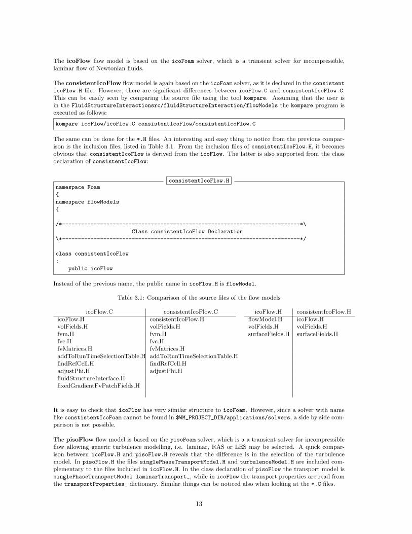
The same can be done for the *.H files. An interesting and easy thing to notice from the previous compar-ison is the inclusion files, listed in Table 3.1. From the inclusion files of consistentIcoFlow.H, it becomesobvious that consistentIcoFlow is derived from the icoFlow. The latter is also supported from the classdeclaration of consistentIcoFlow:
consistentIcoFlow.Hnamespace Foam
{
namespace flowModels
{
/*---------------------------------------------------------------------------*\
Class consistentIcoFlow Declaration
\*---------------------------------------------------------------------------*/
class consistentIcoFlow
:
public icoFlow
Instead of the previous name, the public name in icoFlow.H is flowModel.
Table 3.1: Comparison of the source files of the flow models
icoFlow.C consistentIcoFlow.C icoFlow.H consistentIcoFlow.HicoFlow.H consistentIcoFlow.H flowModel.H icoFlow.HvolFields.H volFields.H volFields.H volFields.Hfvm.H fvm.H surfaceFields.H surfaceFields.Hfvc.H fvc.HfvMatrices.H fvMatrices.HaddToRunTimeSelectionTable.H addToRunTimeSelectionTable.HfindRefCell.H findRefCell.HadjustPhi.H adjustPhi.HfluidStructureInterface.HfixedGradientFvPatchFields.H
It is easy to check that icoFlow has very similar structure to icoFoam. However, since a solver with namelike constistentIcoFoam cannot be found in $WM_PROJECT_DIR/applications/solvers, a side by side com-parison is not possible.
The pisoFlow flow model is based on the pisoFoam solver, which is a a transient solver for incompressibleflow allowing generic turbulence modelling, i.e. laminar, RAS or LES may be selected. A quick compar-ison between icoFlow.H and pisoFlow.H reveals that the difference is in the selection of the turbulencemodel. In pisoFlow.H the files singlePhaseTransportModel.H and turbulenceModel.H are included com-plementary to the files included in icoFlow.H. In the class declaration of pisoFlow the transport model issinglePhaseTransportModel laminarTransport_, while in icoFlow the transport properties are read fromthe transportProperties_ dictionary. Similar things can be noticed also when looking at the *.C files.
13
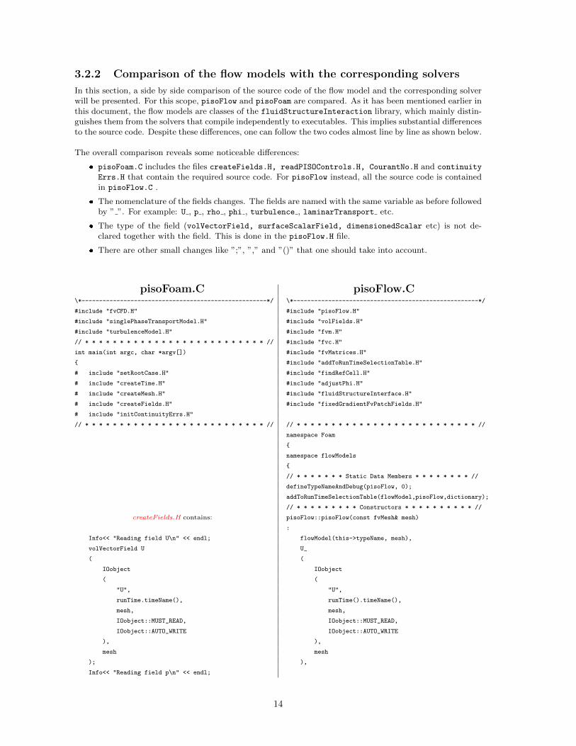
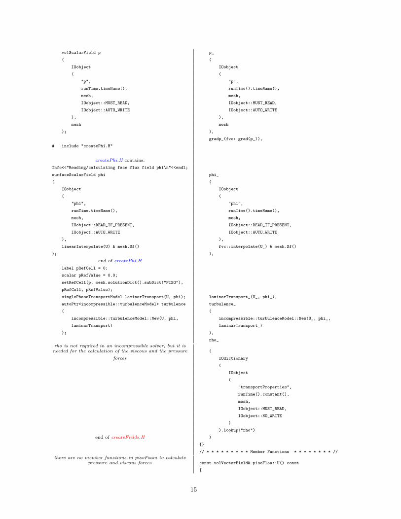
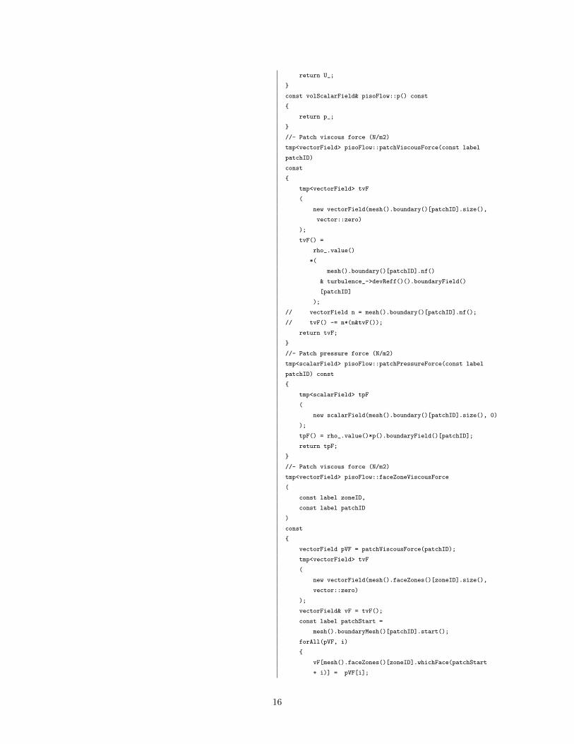
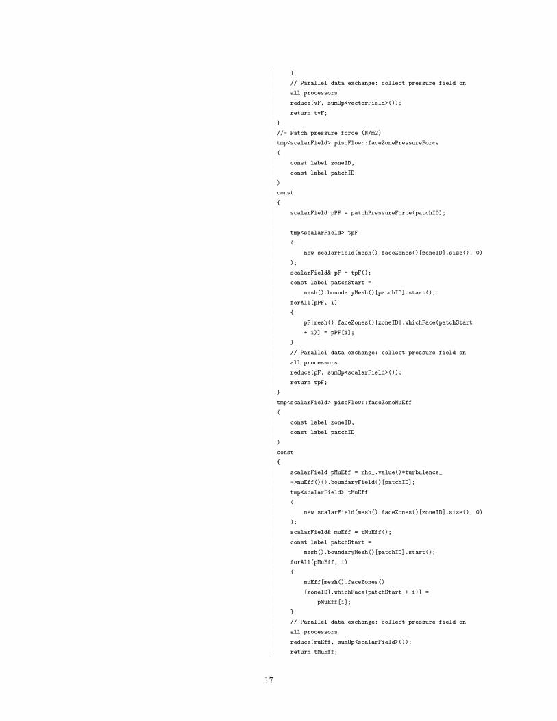
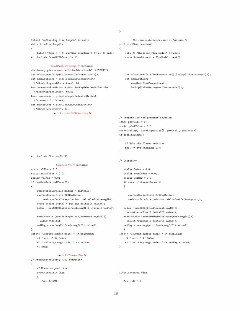
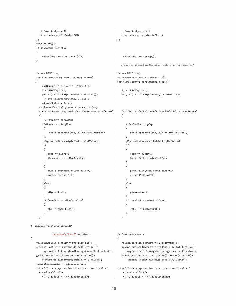
3.2.2 Comparison of the flow models with the corresponding solvers
In this section, a side by side comparison of the source code of the flow model and the corresponding solverwill be presented. For this scope, pisoFlow and pisoFoam are compared. As it has been mentioned earlier inthis document, the flow models are classes of the fluidStructureInteraction library, which mainly distin-guishes them from the solvers that compile independently to executables. This implies substantial differencesto the source code. Despite these differences, one can follow the two codes almost line by line as shown below.
The overall comparison reveals some noticeable differences:
� pisoFoam.C includes the files createFields.H, readPISOControls.H, CourantNo.H and continuity
Errs.H that contain the required source code. For pisoFlow instead, all the source code is containedin pisoFlow.C .
� The nomenclature of the fields changes. The fields are named with the same variable as before followedby ” ”. For example: U , p , rho , phi , turbulence , laminarTransport etc.
� The type of the field (volVectorField, surfaceScalarField, dimensionedScalar etc) is not de-clared together with the field. This is done in the pisoFlow.H file.
� There are other small changes like ”;”, ”,” and ”()” that one should take into account.
pisoFoam.C pisoFlow.C\*-----------------------------------------------------*/ \*-----------------------------------------------------*/
#include "fvCFD.H" #include "pisoFlow.H"
#include "singlePhaseTransportModel.H" #include "volFields.H"
#include "turbulenceModel.H" #include "fvm.H"
// * * * * * * * * * * * * * * * * * * * * * * * * * * // #include "fvc.H"
int main(int argc, char *argv[]) #include "fvMatrices.H"
{ #include "addToRunTimeSelectionTable.H"
# include "setRootCase.H" #include "findRefCell.H"
# include "createTime.H" #include "adjustPhi.H"
# include "createMesh.H" #include "fluidStructureInterface.H"
# include "createFields.H" #include "fixedGradientFvPatchFields.H"
# include "initContinuityErrs.H"
// * * * * * * * * * * * * * * * * * * * * * * * * * * // // * * * * * * * * * * * * * * * * * * * * * * * * * * //
namespace Foam
{
namespace flowModels
{
// * * * * * * * Static Data Members * * * * * * * * //
defineTypeNameAndDebug(pisoFlow, 0);
addToRunTimeSelectionTable(flowModel,pisoFlow,dictionary);
// * * * * * * * * * Constructors * * * * * * * * * * //
createFields.H contains: pisoFlow::pisoFlow(const fvMesh& mesh)
:
Info<< "Reading field U\n" << endl; flowModel(this->typeName, mesh),
volVectorField U U_
( (
IOobject IOobject
( (
"U", "U",
runTime.timeName(), runTime().timeName(),
mesh, mesh,
IOobject::MUST_READ, IOobject::MUST_READ,
IOobject::AUTO_WRITE IOobject::AUTO_WRITE
), ),
mesh mesh
); ),
Info<< "Reading field p\n" << endl;
14
volScalarField p p_
( (
IOobject IOobject
( (
"p", "p",
runTime.timeName(), runTime().timeName(),
mesh, mesh,
IOobject::MUST_READ, IOobject::MUST_READ,
IOobject::AUTO_WRITE IOobject::AUTO_WRITE
), ),
mesh mesh
); ),
gradp_(fvc::grad(p_)),
# include "createPhi.H"
createPhi.H contains:
Info<<"Reading/calculating face flux field phi\n"<<endl;
surfaceScalarField phi phi_
( (
IOobject IOobject
( (
"phi", "phi",
runTime.timeName(), runTime().timeName(),
mesh, mesh,
IOobject::READ_IF_PRESENT, IOobject::READ_IF_PRESENT,
IOobject::AUTO_WRITE IOobject::AUTO_WRITE
), ),
linearInterpolate(U) & mesh.Sf() fvc::interpolate(U_) & mesh.Sf()
); ),
end of createPhi.H
label pRefCell = 0;
scalar pRefValue = 0.0;
setRefCell(p, mesh.solutionDict().subDict("PISO"),
pRefCell, pRefValue);
singlePhaseTransportModel laminarTransport(U, phi); laminarTransport_(U_, phi_),
autoPtr<incompressible::turbulenceModel> turbulence turbulence_
( (
incompressible::turbulenceModel::New(U, phi, incompressible::turbulenceModel::New(U_, phi_,
laminarTransport) laminarTransport_)
); ),
rho_
rho is not required in an incompressible solver, but it isneeded for the calculation of the viscous and the pressure (
forces IOdictionary
(
IOobject
(
"transportProperties",
runTime().constant(),
mesh,
IOobject::MUST_READ,
IOobject::NO_WRITE
)
).lookup("rho")
end of createFields.H )
{}
// * * * * * * * * * Member Functions * * * * * * * * //
there are no member functions in pisoFoam to calculatepressure and viscous forces const volVectorField& pisoFlow::U() const
{
15
return U_;
}
const volScalarField& pisoFlow::p() const
{
return p_;
}
//- Patch viscous force (N/m2)
tmp<vectorField> pisoFlow::patchViscousForce(const label
patchID)
const
{
tmp<vectorField> tvF
(
new vectorField(mesh().boundary()[patchID].size(),
vector::zero)
);
tvF() =
rho_.value()
*(
mesh().boundary()[patchID].nf()
& turbulence_->devReff()().boundaryField()
[patchID]
);
// vectorField n = mesh().boundary()[patchID].nf();
// tvF() -= n*(n&tvF());
return tvF;
}
//- Patch pressure force (N/m2)
tmp<scalarField> pisoFlow::patchPressureForce(const label
patchID) const
{
tmp<scalarField> tpF
(
new scalarField(mesh().boundary()[patchID].size(), 0)
);
tpF() = rho_.value()*p().boundaryField()[patchID];
return tpF;
}
//- Patch viscous force (N/m2)
tmp<vectorField> pisoFlow::faceZoneViscousForce
(
const label zoneID,
const label patchID
)
const
{
vectorField pVF = patchViscousForce(patchID);
tmp<vectorField> tvF
(
new vectorField(mesh().faceZones()[zoneID].size(),
vector::zero)
);
vectorField& vF = tvF();
const label patchStart =
mesh().boundaryMesh()[patchID].start();
forAll(pVF, i)
{
vF[mesh().faceZones()[zoneID].whichFace(patchStart
+ i)] = pVF[i];
16
}
// Parallel data exchange: collect pressure field on
all processors
reduce(vF, sumOp<vectorField>());
return tvF;
}
//- Patch pressure force (N/m2)
tmp<scalarField> pisoFlow::faceZonePressureForce
(
const label zoneID,
const label patchID
)
const
{
scalarField pPF = patchPressureForce(patchID);
tmp<scalarField> tpF
(
new scalarField(mesh().faceZones()[zoneID].size(), 0)
);
scalarField& pF = tpF();
const label patchStart =
mesh().boundaryMesh()[patchID].start();
forAll(pPF, i)
{
pF[mesh().faceZones()[zoneID].whichFace(patchStart
+ i)] = pPF[i];
}
// Parallel data exchange: collect pressure field on
all processors
reduce(pF, sumOp<scalarField>());
return tpF;
}
tmp<scalarField> pisoFlow::faceZoneMuEff
(
const label zoneID,
const label patchID
)
const
{
scalarField pMuEff = rho_.value()*turbulence_
->nuEff()().boundaryField()[patchID];
tmp<scalarField> tMuEff
(
new scalarField(mesh().faceZones()[zoneID].size(), 0)
);
scalarField& muEff = tMuEff();
const label patchStart =
mesh().boundaryMesh()[patchID].start();
forAll(pMuEff, i)
{
muEff[mesh().faceZones()
[zoneID].whichFace(patchStart + i)] =
pMuEff[i];
}
// Parallel data exchange: collect pressure field on
all processors
reduce(muEff, sumOp<scalarField>());
return tMuEff;
17
}
Info<< "\nStarting time loop\n" << endl; the info statements exist in fsiFoam.C
while (runTime.loop()) void pisoFlow::evolve()
{ {
Info<< "Time = " << runTime.timeName() << nl << endl; Info << "Evolving flow model" << endl;
# include "readPISOControls.H" const fvMesh& mesh = flowModel::mesh();
readPISOControls.H contains:
dictionary piso = mesh.solutionDict().subDict("PISO");
int nCorr(readInt(piso.lookup("nCorrectors"))); int nCorr(readInt(flowProperties().lookup("nCorrectors")));
int nNonOrthCorr = piso.lookupOrDefault<int> int nNonOrthCorr =
("nNonOrthogonalCorrectors", 0); readInt(flowProperties().
bool momentumPredictor = piso.lookupOrDefault<Switch> lookup("nNonOrthogonalCorrectors"));
("momentumPredictor", true);
bool transonic = piso.lookupOrDefault<Switch>
("transonic", false);
int nOuterCorr = piso.lookupOrDefault<int>
("nOuterCorrectors", 1);
end of readPISOControls.H
// Prepare for the pressure solution
label pRefCell = 0;
scalar pRefValue = 0.0;
setRefCell(p_, flowProperties(), pRefCell, pRefValue);
if(mesh.moving())
{
// Make the fluxes relative
phi_ -= fvc::meshPhi(U_);
}
# include "CourantNo.H"
// CourantNo
CourantNo.H contains: {
scalar CoNum = 0.0; scalar CoNum = 0.0;
scalar meanCoNum = 0.0; scalar meanCoNum = 0.0;
scalar velMag = 0.0; scalar velMag = 0.0;
if (mesh.nInternalFaces()) if (mesh.nInternalFaces())
{ {
surfaceScalarField magPhi = mag(phi);
surfaceScalarField SfUfbyDelta = surfaceScalarField SfUfbyDelta =
mesh.surfaceInterpolation::deltaCoeffs()*magPhi; mesh.surfaceInterpolation::deltaCoeffs()*mag(phi_);
const scalar deltaT = runTime.deltaT().value();
CoNum = max(SfUfbyDelta/mesh.magSf()).value()*deltaT; CoNum = max(SfUfbyDelta/mesh.magSf()).
value()*runTime().deltaT().value();
meanCoNum = (sum(SfUfbyDelta)/sum(mesh.magSf())). meanCoNum = (sum(SfUfbyDelta)/sum(mesh.magSf())).
value()*deltaT; value()*runTime().deltaT().value();
velMag = max(magPhi/mesh.magSf()).value(); velMag = max(mag(phi_)/mesh.magSf()).value();
} }
Info<< "Courant Number mean: " << meanCoNum Info<< "Courant Number mean: " << meanCoNum
<< " max: " << CoNum << " max: " << CoNum
<< " velocity magnitude: " << velMag << " velocity magnitude: " << velMag << endl;
<< endl; }
end of CourantNo.H
// Pressure-velocity PISO corrector
{
// Momentum predictor
fvVectorMatrix UEqn fvVectorMatrix UEqn
( (
fvm::ddt(U) fvm::ddt(U_)
18
+ fvm::div(phi, U) + fvm::div(phi_, U_)
+ turbulence->divDevReff(U) + turbulence_->divDevReff(U_)
); );
UEqn.relax();
if (momentumPredictor)
{
solve(UEqn == -fvc::grad(p)); solve(UEqn == -gradp_);
}
gradp is defined in the constructors as fvc::grad(p )
// --- PISO loop // --- PISO loop
for (int corr = 0; corr < nCorr; corr++) volScalarField rUA = 1.0/UEqn.A();
{ for (int corr=0; corr<nCorr; corr++)
volScalarField rUA = 1.0/UEqn.A(); {
U = rUA*UEqn.H(); U_ = rUA*UEqn.H();
phi = (fvc::interpolate(U) & mesh.Sf()) phi_ = (fvc::interpolate(U_) & mesh.Sf());
+ fvc::ddtPhiCorr(rUA, U, phi);
adjustPhi(phi, U, p);
// Non-orthogonal pressure corrector loop
for (int nonOrth=0; nonOrth<=nNonOrthCorr;nonOrth++) for (int nonOrth=0; nonOrth<=nNonOrthCorr; nonOrth++)
{ {
// Pressure corrector
fvScalarMatrix pEqn fvScalarMatrix pEqn
( (
fvm::laplacian(rUA, p) == fvc::div(phi) fvm::laplacian(rUA, p_) == fvc::div(phi_)
); );
pEqn.setReference(pRefCell, pRefValue); pEqn.setReference(pRefCell, pRefValue);
if if
( (
corr == nCorr-1 corr == nCorr-1
&& nonOrth == nNonOrthCorr && nonOrth == nNonOrthCorr
) )
{ {
pEqn.solve(mesh.solutionDict(). pEqn.solve(mesh.solutionDict().
solver("pFinal")); solver("pFinal"));
} }
else else
{ {
pEqn.solve(); pEqn.solve();
} }
if (nonOrth == nNonOrthCorr) if (nonOrth == nNonOrthCorr)
{ {
phi -= pEqn.flux(); phi_ -= pEqn.flux();
} }
} }
# include "continuityErrs.H"
continuityErrs.H contains: // Continuity error
{ {
volScalarField contErr = fvc::div(phi); volScalarField contErr = fvc::div(phi_);
sumLocalContErr = runTime.deltaT().value()* scalar sumLocalContErr = runTime().deltaT().value()*
mag(contErr)().weightedAverage(mesh.V()).value(); mag(contErr)().weightedAverage(mesh.V()).value();
globalContErr = runTime.deltaT().value()* scalar globalContErr = runTime().deltaT().value()*
contErr.weightedAverage(mesh.V()).value(); contErr.weightedAverage(mesh.V()).value();
cumulativeContErr += globalContErr;
Info<< "time step continuity errors : sum local =" Info<< "time step continuity errors : sum local = "
<< sumLocalContErr << sumLocalContErr
<< ", global = " << globalContErr << ", global = " << globalContErr
19
<< ", cumulative = " << cumulativeContErr
<< endl; << endl;
} }
end of continuityErrs.H
gradp_ = fvc::grad(p_);
U -= rUA*fvc::grad(p); U_ -= rUA*gradp_;
U.correctBoundaryConditions(); U_.correctBoundaryConditions();
} }
}
turbulence->correct(); turbulence_->correct();
runTime.write();
Info<< "ExecutionTime = " << runTime.elapsedCpuTime()
<< " s"
<< " ClockTime = " << runTime.elapsedClockTime() }
<< " s"
<< nl << endl; // * * * * * * * * * * * * * * * * * * * * * * * * * //
}
Info<< "End\n" << endl; } // End namespace flowModels
return 0; } // End namespace Foam
}
// *************************************************** // // ************************************************ //
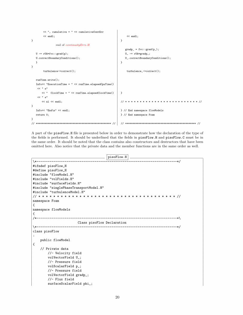
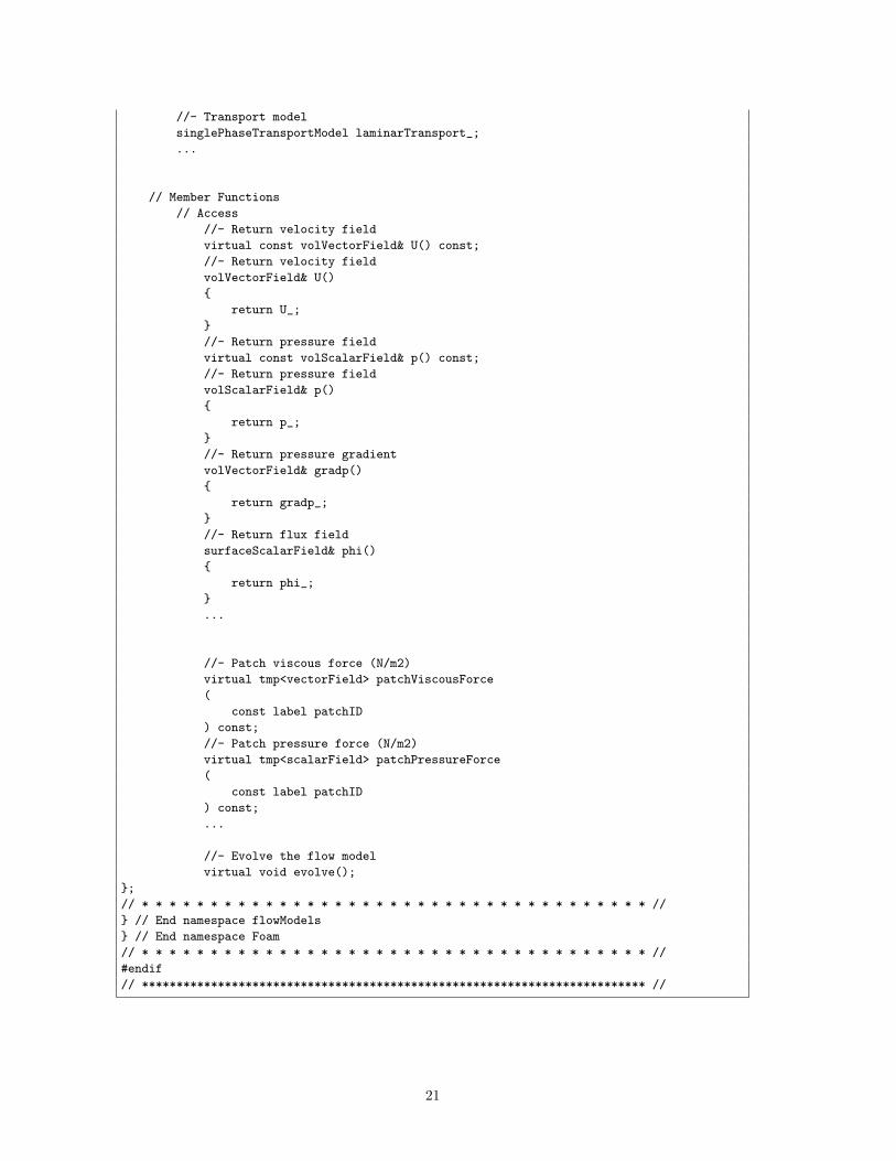
A part of the pisoFlow.H file is presented below in order to demonstrate how the declaration of the type ofthe fields is performed. It should be underlined that the fields in pisoFlow.H and pisoFlow.C must be inthe same order. It should be noted that the class contains also constructors and destructors that have beenomitted here. Also notice that the private data and the member functions are in the same order as well.
pisoFlow.H
\*---------------------------------------------------------------------------*/
#ifndef pisoFlow_H
#define pisoFlow_H
#include "flowModel.H"
#include "volFields.H"
#include "surfaceFields.H"
#include "singlePhaseTransportModel.H"
#include "turbulenceModel.H"
// * * * * * * * * * * * * * * * * * * * * * * * * * * * * * * * * * * * * * //
namespace Foam
{
namespace flowModels
{
/*---------------------------------------------------------------------------*\
Class pisoFlow Declaration
\*---------------------------------------------------------------------------*/
class pisoFlow
:
public flowModel
{
// Private data
//- Velocity field
volVectorField U_;
//- Pressure field
volScalarField p_;
//- Pressure field
volVectorField gradp_;
//- Flux field
surfaceScalarField phi_;
20
//- Transport model
singlePhaseTransportModel laminarTransport_;
...
// Member Functions
// Access
//- Return velocity field
virtual const volVectorField& U() const;
//- Return velocity field
volVectorField& U()
{
return U_;
}
//- Return pressure field
virtual const volScalarField& p() const;
//- Return pressure field
volScalarField& p()
{
return p_;
}
//- Return pressure gradient
volVectorField& gradp()
{
return gradp_;
}
//- Return flux field
surfaceScalarField& phi()
{
return phi_;
}
...
//- Patch viscous force (N/m2)
virtual tmp<vectorField> patchViscousForce
(
const label patchID
) const;
//- Patch pressure force (N/m2)
virtual tmp<scalarField> patchPressureForce
(
const label patchID
) const;
...
//- Evolve the flow model
virtual void evolve();
};
// * * * * * * * * * * * * * * * * * * * * * * * * * * * * * * * * * * * * * //
} // End namespace flowModels
} // End namespace Foam
// * * * * * * * * * * * * * * * * * * * * * * * * * * * * * * * * * * * * * //
#endif
// ************************************************************************* //
21
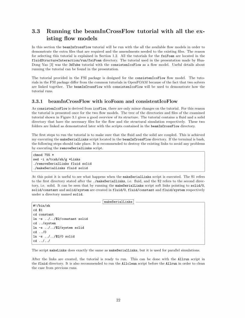
3.3 Running the beamInCrossFlow tutorial with all the ex-isting flow models
In this section the beamInCrossFlow tutorial will be run with the all the available flow models in order todemonstrate the extra files that are required and the amendments needed to the existing files. The reasonfor selecting this tutorial is explained in Section 1.2. All the tutorials for the fsiFoam are located in thefluidStructureInteraction/run/fsiFoam directory. The tutorial used in the presentation made by Hua-Dong Yao [3] was the 3dTube tutorial with the consistenIcoFlow as a flow model. Useful details aboutrunning the tutorial can be found in the presentation.
The tutorial provided in the FSI package is designed for the consistenIcoFlow flow model. The tuto-rials in the FSI package differ from the common tutorials in OpenFOAM because of the fact that two solversare linked together. The beamInCrossFlow with consistenIcoFlow will be used to demonstrate how thetutorial runs.
3.3.1 beamInCrossFlow with icoFoam and consistentIcoFlow
As consistenIcoFlow is derived from icoFlow, there are only minor changes on the tutorial. For this reasonthe tutorial is presented once for the two flow models. The tree of the directories and files of the examinedtutorial shown in Figure 3.1 gives a good overview of its structure. The tutorial contains a fluid and a soliddirectory that have the necessary files for the flow and the structural simulation respectively. These twofolders are linked as demonstrated later with the scripts contained in the beamInCrossFlow directory.
The first steps to run the tutorial is to make sure that the fluid and the solid are coupled. This is achievedmy executing the makeSerialLinks script located in the beamInCrossFlow directory. If the terminal is bash,the following steps should take place. It is recommended to destroy the existing links to avoid any problemsby executing the removeSerialLinks script.
chmod 755 *
sed -i s/tcsh/sh/g *Links
./removeSerialLinks fluid solid
./makeSerialLinks fluid solid
At this point it is useful to see what happens when the makeSerialLinks script is executed. The $1 refersto the first directory stated after the ./makeSerialLinks, i.e. fluid, and the $2 refers to the second direc-tory, i.e. solid. It can be seen that by running the makeSerialLinks script soft links pointing to solid/0,solid/constant and solid/system are created in fluid/0, fluid/constant and fluid/system respectivelyunder a directory named solid.
makeSerialLinks#!/bin/sh
cd $1
cd constant
ln -s ../../$2/constant solid
cd ../system
ln -s ../../$2/system solid
cd ../0
ln -s ../../$2/0 solid
cd ../../
The script makeLinks does exactly the same as makeSerialLinks, but it is used for parallel simulations.
After the links are created, the tutorial is ready to run. This can be done with the Allrun script inthe fluid directory. It is also recommended to run the Allclean script before the Allrun in order to cleanthe case from previous runs.
22
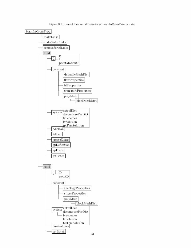
Figure 3.1: Tree of files and directories of beamInCrossFlow tutorial
beamInCrossFlow
makeLinks
makeSerialLinks
removeSerialLinks
fluid
0pUpointMotionU
constant
dynamicMeshDict
flowProperties
fsiProperties
transportProperties
polyMesh
blockMeshDict
systemcntrolDictdecomposeParDictfvSchemesfvSolutiontetFemSolution
Allclean
Allrun
createZones
gpDeflection
gpForce
setBatch
solid
0 DpointD
constant
rheologyProperties
stressProperties
polyMesh
blockMeshDict
systemcntrolDictdecomposeParDictfvSchemesfvSolutiontetFemSolution
createZones
setBatch23
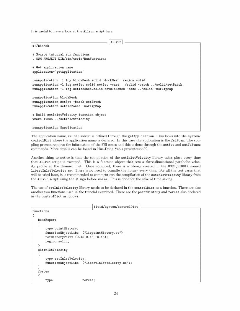
It is useful to have a look at the Allrun script here.
Allrun#!/bin/sh
# Source tutorial run functions
. $WM_PROJECT_DIR/bin/tools/RunFunctions
# Get application name
application=`getApplication`
runApplication -l log.blockMesh.solid blockMesh -region solid
runApplication -l log.setSet.solid setSet -case ../solid -batch ../solid/setBatch
runApplication -l log.setToZones.solid setsToZones -case ../solid -noFlipMap
runApplication blockMesh
runApplication setSet -batch setBatch
runApplication setsToZones -noFlipMap
# Build setInletVelocity function object
wmake libso ../setInletVelocity
runApplication $application
The application name, i.e. the solver, is defined through the getApplication. This looks into the system/
controlDict where the application name is declared. In this case the application is the fsiFoam. The cou-pling process requires the information of the FSI zones and this is done through the setSet and setToZones
commands. More details can be found in Hua-Dong Yao’s presentation[3].
Another thing to notice is that the compilation of the setInletVelocity library takes place every timethat Allrun script is executed. This is a function object that sets a three-dimensional parabolic veloc-ity profile at the channel inlet. Once compiled, there is a library created in the USER_LIBBIN namedlibsetInletVelocity.so. There is no need to compile the library every time. For all the test cases thatwill be tried later, it is recommended to comment out the compilation of the setInletVelocity library fromthe Allrun script using the # sign before wmake. This is done for the sake of time saving.
The use of setInletVelocity library needs to be declared in the controlDict as a function. There are alsoanother two functions used in the tutorial examined. These are the pointHistory and forces also declaredin the controlDict as follows.
fluid/system/controlDict
functions
(
beamReport
{
type pointHistory;
functionObjectLibs ("libpointHistory.so");
refHistoryPoint (0.45 0.15 -0.15);
region solid;
}
setInletVelocity
{
type setInletVelocity;
functionObjectLibs ("libsetInletVelocity.so");
}
forces
{
type forces;
24
functionObjectLibs ( "libforces.so" );
outputControl timeStep;
outputInterval 1;
patches (interface);
pName p;
UName U;
rhoName rhoInf;
log true;
rhoInf 1000;
CofR (0.5 0.1 0);
}
);
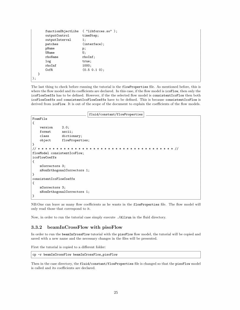
The last thing to check before running the tutorial is the flowProperties file. As mentioned before, this iswhere the flow model and its coefficients are declared. In this case, if the flow model is icoFlow, then only theicoFlowCoeffs has to be defined. However, if the the selected flow model is consistentIcoFlow then bothicoFlowCoeffs and consistentIcoFlowCoeffs have to be defined. This is because consistentIcoFlow isderived from icoFlow. It is out of the scope of the document to explain the coefficients of the flow models.
fluid/constant/flowProperties
FoamFile
{
version 2.0;
format ascii;
class dictionary;
object flowProperties;
}
// * * * * * * * * * * * * * * * * * * * * * * * * * * * * * * * * * * * * * //
flowModel consistentIcoFlow;
icoFlowCoeffs
{
nCorrectors 3;
nNonOrthogonalCorrectors 1;
}
consistentIcoFlowCoeffs
{
nCorrectors 3;
nNonOrthogonalCorrectors 1;
}
NB:One can leave as many flow coefficients as he wants in the flowProperties file. The flow model willonly read those that correspond to it.
Now, in order to run the tutorial case simply execute ./Allrun in the fluid directory.
3.3.2 beamInCrossFlow with pisoFlow
In order to run the beamInCrossFlow tutorial with the pisoFlow flow model, the tutorial will be copied andsaved with a new name and the necessary changes in the files will be presented.
First the tutorial is copied to a different folder:
cp -r beamInCrossFlow beamInCrossFlow_pisoFlow
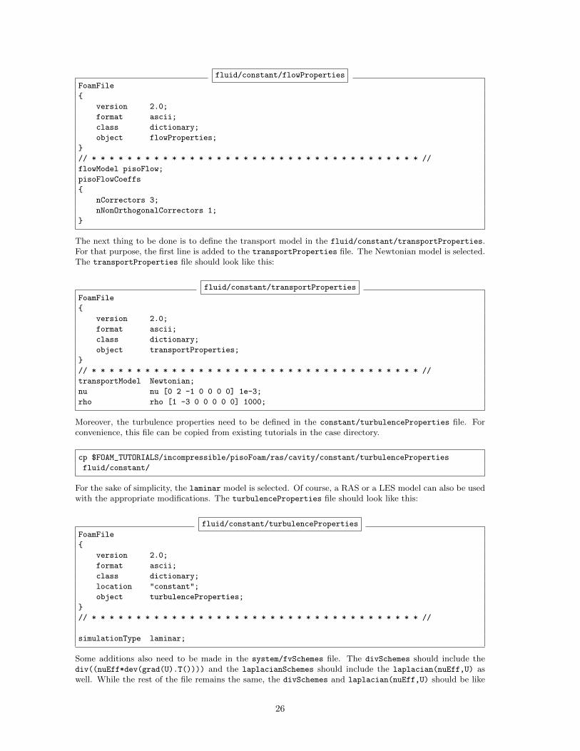
Then in the case directory, the fluid/constant/flowProperties file is changed so that the pisoFlow modelis called and its coefficients are declared.
25
fluid/constant/flowProperties
FoamFile
{
version 2.0;
format ascii;
class dictionary;
object flowProperties;
}
// * * * * * * * * * * * * * * * * * * * * * * * * * * * * * * * * * * * * * //
flowModel pisoFlow;
pisoFlowCoeffs
{
nCorrectors 3;
nNonOrthogonalCorrectors 1;
}
The next thing to be done is to define the transport model in the fluid/constant/transportProperties.For that purpose, the first line is added to the transportProperties file. The Newtonian model is selected.The transportProperties file should look like this:
fluid/constant/transportProperties
FoamFile
{
version 2.0;
format ascii;
class dictionary;
object transportProperties;
}
// * * * * * * * * * * * * * * * * * * * * * * * * * * * * * * * * * * * * * //
transportModel Newtonian;
nu nu [0 2 -1 0 0 0 0] 1e-3;
rho rho [1 -3 0 0 0 0 0] 1000;
Moreover, the turbulence properties need to be defined in the constant/turbulenceProperties file. Forconvenience, this file can be copied from existing tutorials in the case directory.
cp $FOAM_TUTORIALS/incompressible/pisoFoam/ras/cavity/constant/turbulenceProperties
fluid/constant/
For the sake of simplicity, the laminar model is selected. Of course, a RAS or a LES model can also be usedwith the appropriate modifications. The turbulenceProperties file should look like this:
fluid/constant/turbulenceProperties
FoamFile
{
version 2.0;
format ascii;
class dictionary;
location "constant";
object turbulenceProperties;
}
// * * * * * * * * * * * * * * * * * * * * * * * * * * * * * * * * * * * * * //
simulationType laminar;
Some additions also need to be made in the system/fvSchemes file. The divSchemes should include thediv((nuEff*dev(grad(U).T()))) and the laplacianSchemes should include the laplacian(nuEff,U) aswell. While the rest of the file remains the same, the divSchemes and laplacian(nuEff,U) should be like
26
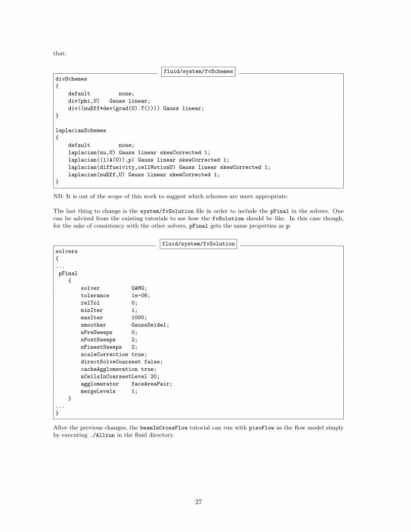
that:
fluid/system/fvSchemes
divSchemes
{
default none;
div(phi,U) Gauss linear;
div((nuEff*dev(grad(U).T()))) Gauss linear;
}
laplacianSchemes
{
default none;
laplacian(nu,U) Gauss linear skewCorrected 1;
laplacian((1|A(U)),p) Gauss linear skewCorrected 1;
laplacian(diffusivity,cellMotionU) Gauss linear skewCorrected 1;
laplacian(nuEff,U) Gauss linear skewCorrected 1;
}
NB: It is out of the scope of this work to suggest which schemes are more appropriate.
The last thing to change is the system/fvSolution file in order to include the pFinal in the solvers. Onecan be advised from the existing tutorials to see how the fvSolution should be like. In this case though,for the sake of consistency with the other solvers, pFinal gets the same properties as p:
fluid/system/fvSolution
solvers
{
...
pFinal
{
solver GAMG;
tolerance 1e-06;
relTol 0;
minIter 1;
maxIter 1000;
smoother GaussSeidel;
nPreSweeps 0;
nPostSweeps 2;
nFinestSweeps 2;
scaleCorrection true;
directSolveCoarsest false;
cacheAgglomeration true;
nCellsInCoarsestLevel 20;
agglomerator faceAreaPair;
mergeLevels 1;
}
...
}
After the previous changes, the beamInCrossFlow tutorial can run with pisoFlow as the flow model simplyby executing ./Allrun in the fluid directory.
27
Chapter 4
Building and testing interFlow
In this section, the creation and compilation of a new flow model is demonstrated. The necessary steps forcreating a tutorial for two phase flow will be presented at the end of the chapter.
4.1 Introduction of a new flow model
As it was briefly discussed in the last paragraph of Section 3.1, a flow model is compiled independently andit belongs to the fluidStructureInteraction library. The source code for any flow model consists only ofthe *.C and *.H files. The compilation of a new flow model does not affect the existing models.
For this case the interFlow flow model will be compiled, but one can use exactly the same process tocompile the flow model of his needs. The only thing that needs to be changed is the name. It is importantto remember that once the FSI package is compiled, only the fluidStructureInteraction library has tobe recompiled to include the new flow model and not the whole package. To start with, the new flow modelwill be the exact copy of an existing one. The names of the source files and the class names will be updatedwith the new names. The process is showed below:
cd fluidStructureInteraction/src/fluidStructureInteraction/flowModels
cp -r pisoFlow interFlow
cd interFlow
mv pisoFlow.C interFlow.C
mv pisoFlow.H interFlow.H
sed -i s/pisoFlow/interFlow/g interFlow.*
Up to this point, the source files for the interFlow flow model exist. Of course they are identical to thepisoFlow flow model. Now the compiler needs the extra information required to include interFlow in theflow models. One can manually add the flowModels/interFlow/interFlow.C in the Make/files of thefluidStructureInteraction library or use the terminal command below and compile the library assumingthat he is in the src/fluidStructureInteraction directory.
echo "flowModels/interFlow/interFlow.C" >> Make/files
wmake libso
The fluidStructureInteraction library is now updated containing the interFlow flow model. No changesto the Make/Options were required, since the flow model is a copy of an existing one and all the essentialpaths already exist. In the next section, the the Make/Options file will be updated according to the changesin the source code of the flow model.
The reason that pisoFlow is selected as a starting point is that it allows turbulence modelling, whichwill appear to be useful in the next steps of the work.
NB: One can change the name of the library at the bottom of the Make/files, however it has not been done
28
here for two reasons: a) the library is already compiled in a $FOAM_USER_LIBBIN, so there is no way to harmthe central installation and b) the library already exists and even in the case that the new flow models failto compile the existing can still work. One can change the name of the library, but then he needs to includethe name of the new library in other parts of the FSI package, for example the Make/Options file of thefsiFoam solver. For convenience the original name of the library is kept here.
4.2 Introduction of the two phase fluid flow
Probably, the best way to start working on the introduction of two phase flow in the existing flow model,is to find an existing two phase flow solver. Having a look at $FOAM_SOLVERS/multiphase there is a list ofdifferent solvers. The twoPhaseEulerFoam and the interFoam solver appear to be the most obvious choices.
The interFoam solver is selected as a well tested solver for free surface modelling. More precisely theinterDyMFoam solver, which is similar to the interFoam, but it also allows mesh motion that is necessaryfor the FSI problem. According to its description, interDyMFoam is a solver for 2 incompressible, isothermalimmiscible fluids using a VOF (volume of fluid) phase-fraction based interface capturing approach, withoptional mesh motion and mesh topology changes including adaptive re-meshing.
4.2.1 Comparison of the source code of interDyMFoam and interFlow
In this section, the changes required to the source code of the recently generated interFlow flow model willbe presented. For the sake of clarity, when reference is done to the interFlow code, it will correspond to thecurrent version of interFlow and not its final functional one. It is reminded that at this stage, interFlowis just a copy of pisoFlow.
The first thing to notice when comparing the directory of the source code of a flow model (interFlow)and a flow solver (interDyMFoam) is that the flow model has only the *.C and *.H files, while the solverhas many more *.H files and its own Make directory, since it compiles independently to an executable. Thestrategy that is going to be followed is to merge all the necessary code contained in the *.H files of the flowsolver to the only two files of the flow model, i.e.interFlow.C and interFlow.H. The *.H files contained inthe interDyMFoam source code directory are listed in Table 4.1. It is also important to notice that there area few *.H files that are used from the interFoam source code directory. The latter are in italics.
Table 4.1: Source files of interDyMFoam and interFlow
interDyMFoam interFlowinterDyMFoam.C interFlow.C
correctPhi.H interFlow.HcreateFields.H
pEqn.HreadControls.H
alphaEqnSubCycle.HUEqn.H
It is important to mention that alphaEqn.H is not included directly in the interDyMFoam source code, butit is included in the alphaEqnSubCycle.H file and therefore it should not be omitted.
As mentioned before interFlow is a class and because of that, it cannot include any other source filesafter the namespace in the class declaration, static data members, constructors and member functions.That means that the necessary content of the *.H and *.C files should be copied into the interFlow.C andinterFlow.H files. Another reason that one cannot directly use the existing code of interDyMFoam is thatmany variables have different names in the FSI package. This will be shown later.
The next thing to take into account is the additions required in the fluidStructureInteraction/Make/optionsfile in order to include all the necessary paths that the two phase flow model will need for compiling. Thecorresponding Make/options file of the interDyMFoam solver is presented bellow. The files in blue are thosethat are not initially listed in fluidStructureInteraction/Make/options. These files need to be added.
29
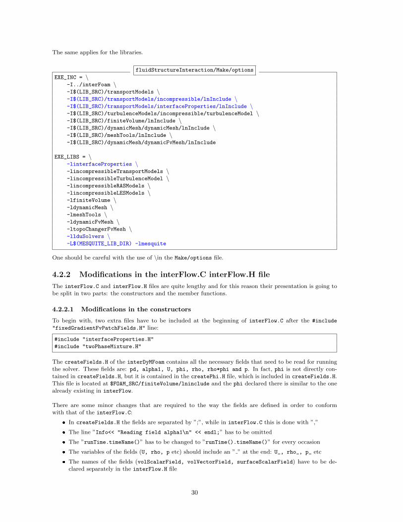
The same applies for the libraries.
fluidStructureInteraction/Make/options
EXE_INC = \-I../interFoam \-I$(LIB_SRC)/transportModels \-I$(LIB_SRC)/transportModels/incompressible/lnInclude \-I$(LIB_SRC)/transportModels/interfaceProperties/lnInclude \-I$(LIB_SRC)/turbulenceModels/incompressible/turbulenceModel \-I$(LIB_SRC)/finiteVolume/lnInclude \-I$(LIB_SRC)/dynamicMesh/dynamicMesh/lnInclude \-I$(LIB_SRC)/meshTools/lnInclude \-I$(LIB_SRC)/dynamicMesh/dynamicFvMesh/lnInclude
EXE_LIBS = \-linterfaceProperties \-lincompressibleTransportModels \-lincompressibleTurbulenceModel \-lincompressibleRASModels \-lincompressibleLESModels \-lfiniteVolume \-ldynamicMesh \-lmeshTools \-ldynamicFvMesh \-ltopoChangerFvMesh \-llduSolvers \-L$(MESQUITE_LIB_DIR) -lmesquite
One should be careful with the use of \in the Make/options file.
4.2.2 Modifications in the interFlow.C interFlow.H file
The interFlow.C and interFlow.H files are quite lengthy and for this reason their presentation is going tobe split in two parts: the constructors and the member functions.
4.2.2.1 Modifications in the constructors
To begin with, two extra files have to be included at the beginning of interFlow.C after the #include
"fixedGradientFvPatchFields.H" line:
#include "interfaceProperties.H"
#include "twoPhaseMixture.H"
The createFields.H of the interDyMFoam contains all the necessary fields that need to be read for runningthe solver. These fields are: pd, alpha1, U, phi, rho, rho*phi and p. In fact, phi is not directly con-tained in createFields.H, but it is contained in the createPhi.H file, which is included in createFields.H.This file is located at $FOAM_SRC/finiteVolume/lninclude and the phi declared there is similar to the onealready existing in interFlow.
There are some minor changes that are required to the way the fields are defined in order to conformwith that of the interFlow.C:
� In createFields.H the fields are separated by ”;”, while in interFlow.C this is done with ”,”
� The line ”Info<< "Reading field alpha1\n" << endl;” has to be omitted
� The ”runTime.timeName()” has to be changed to ”runTime().timeName()” for every occasion
� The variables of the fields (U, rho, p etc) should include an ” ” at the end: U_, rho_, p_ etc
� The names of the fields (volScalarField, volVectorField, surfaceScalarField) have to be de-clared separately in the interFlow.H file
30
The names and types of the fields have to be consistent between interFlow.C and interFlow.H. Moreover,they must have the same order in the two files. It is recommended to add the fields one by one and tocompile the fluidStructureInteraction library after every change. Any errors can be seen in a log file ifthe ”wmake libso > make.log 2>&1” is executed for compiling.
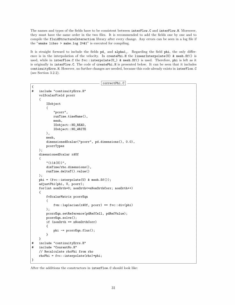
It is straight forward to include the fields pd_ and alpha1_. Regarding the field phi, the only differ-ence is in the interpolation of the velocity. In createPhi.H the linearInterpolate(U) & mesh.Sf() isused, while in interFlow.C the fvc::interpolate(U_) & mesh.Sf() is used. Therefore, phi is left as itis originally in interFlow.C. The code of createPhi.H is presented below. It can be seen that it includescontinuityErrs.H. However, no further changes are needed, because this code already exists in interFlow.C
(see Section 3.2.2).
correctPhi.C{
# include "continuityErrs.H"
volScalarField pcorr
(
IOobject
(
"pcorr",
runTime.timeName(),
mesh,
IOobject::NO_READ,
IOobject::NO_WRITE
),
mesh,
dimensionedScalar("pcorr", pd.dimensions(), 0.0),
pcorrTypes
);
dimensionedScalar rAUf
(
"(1|A(U))",
dimTime/rho.dimensions(),
runTime.deltaT().value()
);
phi = (fvc::interpolate(U) & mesh.Sf());
adjustPhi(phi, U, pcorr);
for(int nonOrth=0; nonOrth<=nNonOrthCorr; nonOrth++)
{
fvScalarMatrix pcorrEqn
(
fvm::laplacian(rAUf, pcorr) == fvc::div(phi)
);
pcorrEqn.setReference(pdRefCell, pdRefValue);
pcorrEqn.solve();
if (nonOrth == nNonOrthCorr)
{
phi -= pcorrEqn.flux();
}
}
# include "continuityErrs.H"
# include "CourantNo.H"
// Recalculate rhoPhi from rho
rhoPhi = fvc::interpolate(rho)*phi;
}
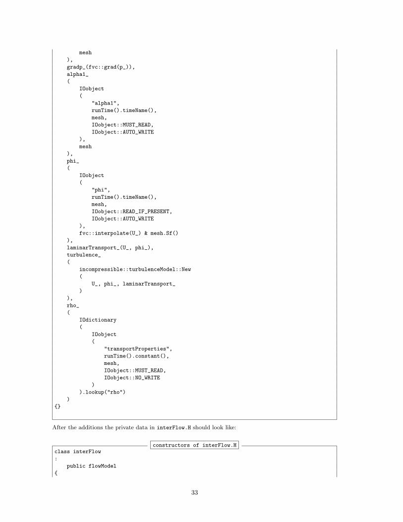
After the additions the constructors in interFlow.C should look like:
31
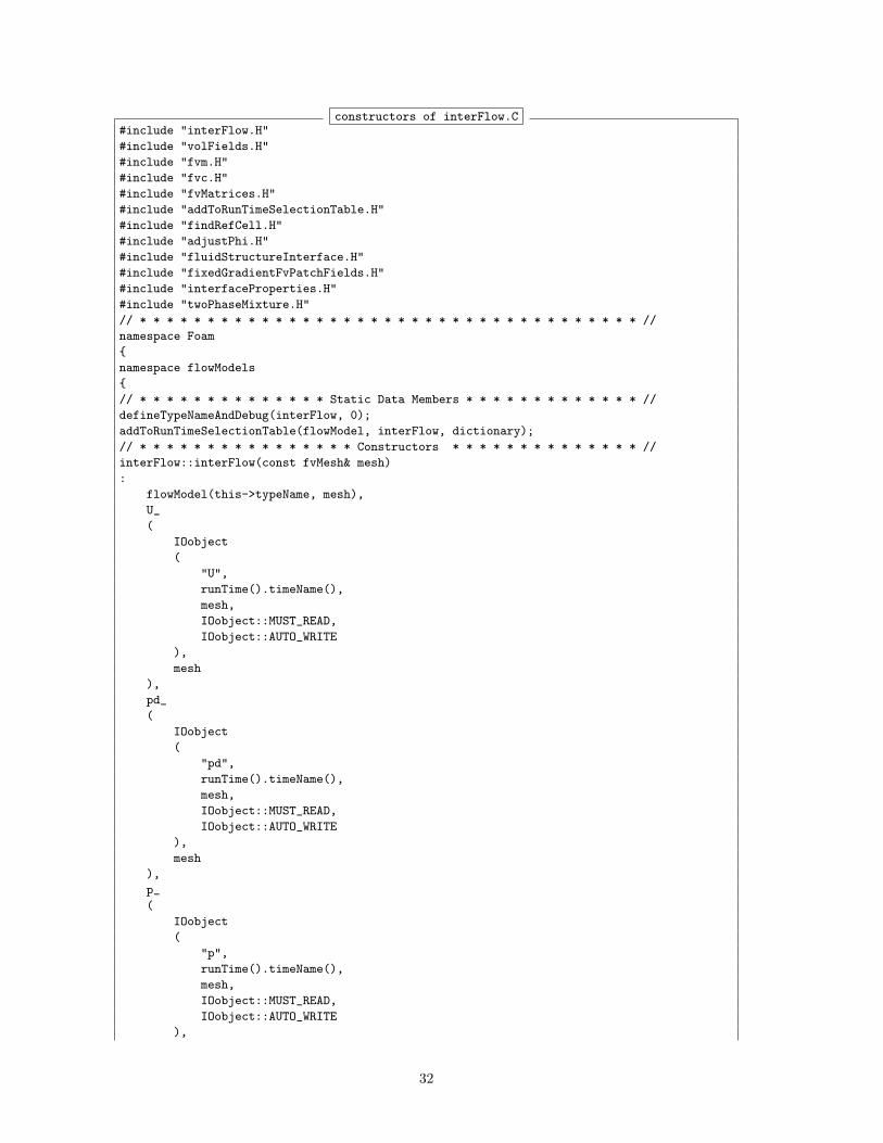
constructors of interFlow.C#include "interFlow.H"
#include "volFields.H"
#include "fvm.H"
#include "fvc.H"
#include "fvMatrices.H"
#include "addToRunTimeSelectionTable.H"
#include "findRefCell.H"
#include "adjustPhi.H"
#include "fluidStructureInterface.H"
#include "fixedGradientFvPatchFields.H"
#include "interfaceProperties.H"
#include "twoPhaseMixture.H"
// * * * * * * * * * * * * * * * * * * * * * * * * * * * * * * * * * * * * * //
namespace Foam
{
namespace flowModels
{
// * * * * * * * * * * * * * * Static Data Members * * * * * * * * * * * * * //
defineTypeNameAndDebug(interFlow, 0);
addToRunTimeSelectionTable(flowModel, interFlow, dictionary);
// * * * * * * * * * * * * * * * * Constructors * * * * * * * * * * * * * * //
interFlow::interFlow(const fvMesh& mesh)
:
flowModel(this->typeName, mesh),
U_
(
IOobject
(
"U",
runTime().timeName(),
mesh,
IOobject::MUST_READ,
IOobject::AUTO_WRITE
),
mesh
),
pd_
(
IOobject
(
"pd",
runTime().timeName(),
mesh,
IOobject::MUST_READ,
IOobject::AUTO_WRITE
),
mesh
),
p_
(
IOobject
(
"p",
runTime().timeName(),
mesh,
IOobject::MUST_READ,
IOobject::AUTO_WRITE
),
32
mesh
),
gradp_(fvc::grad(p_)),
alpha1_
(
IOobject
(
"alpha1",
runTime().timeName(),
mesh,
IOobject::MUST_READ,
IOobject::AUTO_WRITE
),
mesh
),
phi_
(
IOobject
(
"phi",
runTime().timeName(),
mesh,
IOobject::READ_IF_PRESENT,
IOobject::AUTO_WRITE
),
fvc::interpolate(U_) & mesh.Sf()
),
laminarTransport_(U_, phi_),
turbulence_
(
incompressible::turbulenceModel::New
(
U_, phi_, laminarTransport_
)
),
rho_
(
IOdictionary
(
IOobject
(
"transportProperties",
runTime().constant(),
mesh,
IOobject::MUST_READ,
IOobject::NO_WRITE
)
).lookup("rho")
)
{}
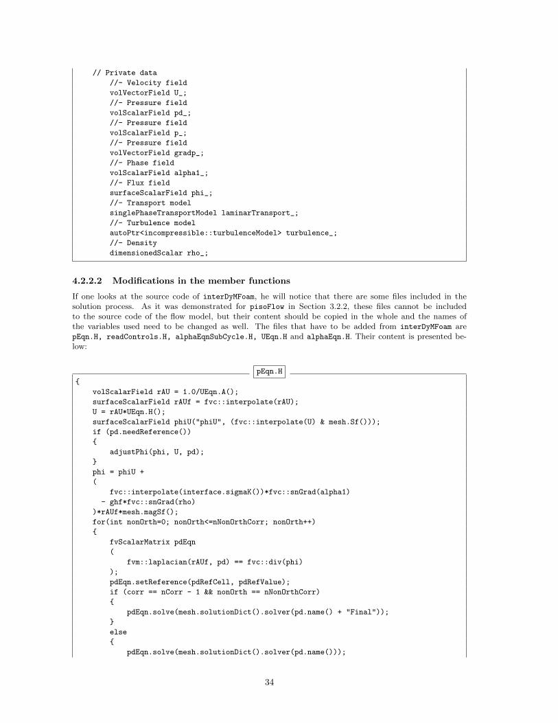
After the additions the private data in interFlow.H should look like:
constructors of interFlow.Hclass interFlow
:
public flowModel
{
33
// Private data
//- Velocity field
volVectorField U_;
//- Pressure field
volScalarField pd_;
//- Pressure field
volScalarField p_;
//- Pressure field
volVectorField gradp_;
//- Phase field
volScalarField alpha1_;
//- Flux field
surfaceScalarField phi_;
//- Transport model
singlePhaseTransportModel laminarTransport_;
//- Turbulence model
autoPtr<incompressible::turbulenceModel> turbulence_;
//- Density
dimensionedScalar rho_;
4.2.2.2 Modifications in the member functions
If one looks at the source code of interDyMFoam, he will notice that there are some files included in thesolution process. As it was demonstrated for pisoFlow in Section 3.2.2, these files cannot be includedto the source code of the flow model, but their content should be copied in the whole and the names ofthe variables used need to be changed as well. The files that have to be added from interDyMFoam arepEqn.H, readControls.H, alphaEqnSubCycle.H, UEqn.H and alphaEqn.H. Their content is presented be-low:
pEqn.H
{
volScalarField rAU = 1.0/UEqn.A();
surfaceScalarField rAUf = fvc::interpolate(rAU);
U = rAU*UEqn.H();
surfaceScalarField phiU("phiU", (fvc::interpolate(U) & mesh.Sf()));
if (pd.needReference())
{
adjustPhi(phi, U, pd);
}
phi = phiU +
(
fvc::interpolate(interface.sigmaK())*fvc::snGrad(alpha1)
- ghf*fvc::snGrad(rho)
)*rAUf*mesh.magSf();
for(int nonOrth=0; nonOrth<=nNonOrthCorr; nonOrth++)
{
fvScalarMatrix pdEqn
(
fvm::laplacian(rAUf, pd) == fvc::div(phi)
);
pdEqn.setReference(pdRefCell, pdRefValue);
if (corr == nCorr - 1 && nonOrth == nNonOrthCorr)
{
pdEqn.solve(mesh.solutionDict().solver(pd.name() + "Final"));
}
else
{
pdEqn.solve(mesh.solutionDict().solver(pd.name()));
34
}
if (nonOrth == nNonOrthCorr)
{
phi -= pdEqn.flux();
}
}
U += rAU*fvc::reconstruct((phi - phiU)/rAUf);
U.correctBoundaryConditions();
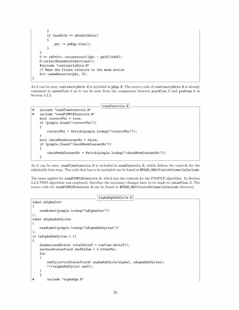
#include "continuityErrs.H"
// Make the fluxes relative to the mesh motion
fvc::makeRelative(phi, U);
}
As it can be seen, continuityErrs.H is included in pEqn.H. The source code of continuityErrs.H is alreadycontained in interFlow.C as it can be seen from the comparison between pisoFlow.C and pisFoam.C inSection 3.2.2.
readControls.H# include "readTimeControls.H"
# include "readPIMPLEControls.H"
bool correctPhi = true;
if (pimple.found("correctPhi"))
{
correctPhi = Switch(pimple.lookup("correctPhi"));
}
bool checkMeshCourantNo = false;
if (pimple.found("checkMeshCourantNo"))
{
checkMeshCourantNo = Switch(pimple.lookup("checkMeshCourantNo"));
}
As it can be seen, readTimeControls.H is included in readControls.H, which defines the controls for theadjustable time step. The code that has to be included can be found in $FOAM_SRC/finiteVolume/lnInclude.
The same applies for readPIMPLEControls.H, which has the controls for the PIMPLE algorithm. In Section3.2.2 PISO algorithm was employed, therefore the necessary changes have to be made to interFlow.C. Thesource code for readPIMPLEControls.H can be found in $FOAM_SRC/finiteVolume/lnInclude directory.
alphaEqnSubCycle.H
label nAlphaCorr
(
readLabel(pimple.lookup("nAlphaCorr"))
);
label nAlphaSubCycles
(
readLabel(pimple.lookup("nAlphaSubCycles"))
);
if (nAlphaSubCycles > 1)
{
dimensionedScalar totalDeltaT = runTime.deltaT();
surfaceScalarField rhoPhiSum = 0.0*rhoPhi;
for
(
subCycle<volScalarField> alphaSubCycle(alpha1, nAlphaSubCycles);
!(++alphaSubCycle).end();
)
{
# include "alphaEqn.H"
35
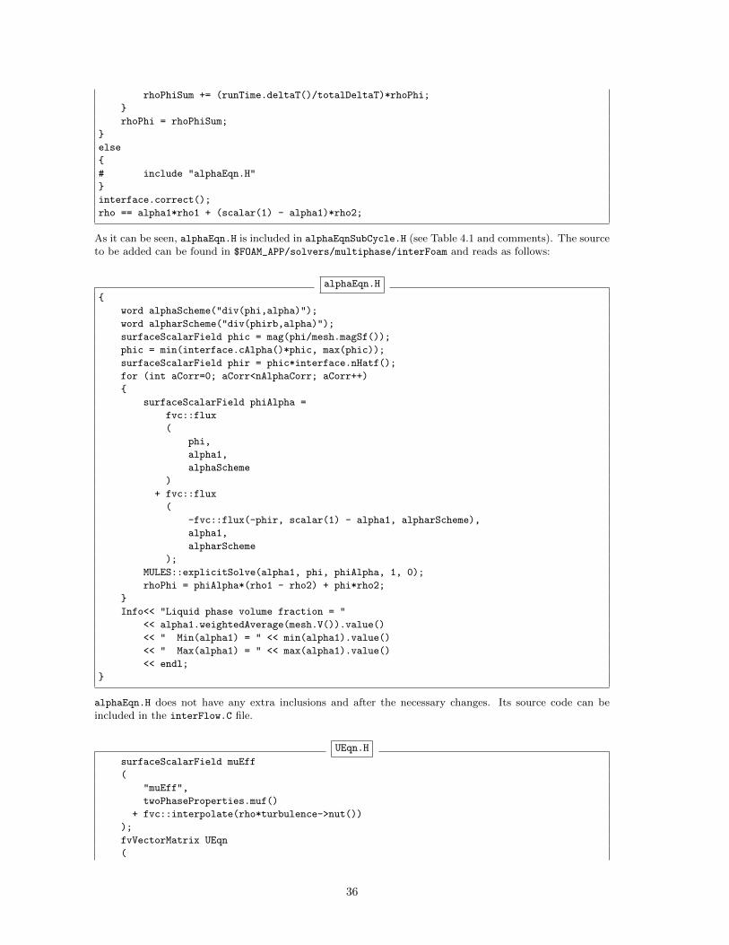
rhoPhiSum += (runTime.deltaT()/totalDeltaT)*rhoPhi;
}
rhoPhi = rhoPhiSum;
}
else
{
# include "alphaEqn.H"
}
interface.correct();
rho == alpha1*rho1 + (scalar(1) - alpha1)*rho2;
As it can be seen, alphaEqn.H is included in alphaEqnSubCycle.H (see Table 4.1 and comments). The sourceto be added can be found in $FOAM_APP/solvers/multiphase/interFoam and reads as follows:
alphaEqn.H
{
word alphaScheme("div(phi,alpha)");
word alpharScheme("div(phirb,alpha)");
surfaceScalarField phic = mag(phi/mesh.magSf());
phic = min(interface.cAlpha()*phic, max(phic));
surfaceScalarField phir = phic*interface.nHatf();
for (int aCorr=0; aCorr<nAlphaCorr; aCorr++)
{
surfaceScalarField phiAlpha =
fvc::flux
(
phi,
alpha1,
alphaScheme
)
+ fvc::flux
(
-fvc::flux(-phir, scalar(1) - alpha1, alpharScheme),
alpha1,
alpharScheme
);
MULES::explicitSolve(alpha1, phi, phiAlpha, 1, 0);
rhoPhi = phiAlpha*(rho1 - rho2) + phi*rho2;
}
Info<< "Liquid phase volume fraction = "
<< alpha1.weightedAverage(mesh.V()).value()
<< " Min(alpha1) = " << min(alpha1).value()
<< " Max(alpha1) = " << max(alpha1).value()
<< endl;
}
alphaEqn.H does not have any extra inclusions and after the necessary changes. Its source code can beincluded in the interFlow.C file.
UEqn.H
surfaceScalarField muEff
(
"muEff",
twoPhaseProperties.muf()
+ fvc::interpolate(rho*turbulence->nut())
);
fvVectorMatrix UEqn
(
36
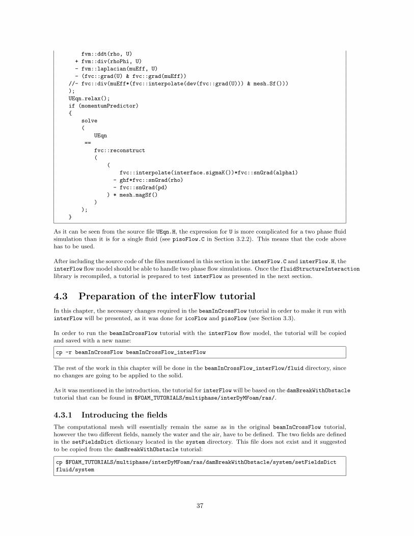
fvm::ddt(rho, U)
+ fvm::div(rhoPhi, U)
- fvm::laplacian(muEff, U)
- (fvc::grad(U) & fvc::grad(muEff))
//- fvc::div(muEff*(fvc::interpolate(dev(fvc::grad(U))) & mesh.Sf()))
);
UEqn.relax();
if (momentumPredictor)
{
solve
(
UEqn
==
fvc::reconstruct
(
(
fvc::interpolate(interface.sigmaK())*fvc::snGrad(alpha1)
- ghf*fvc::snGrad(rho)
- fvc::snGrad(pd)
) * mesh.magSf()
)
);
}
As it can be seen from the source file UEqn.H, the expression for U is more complicated for a two phase fluidsimulation than it is for a single fluid (see pisoFlow.C in Section 3.2.2). This means that the code abovehas to be used.
After including the source code of the files mentioned in this section in the interFlow.C and interFlow.H, theinterFlow flow model should be able to handle two phase flow simulations. Once the fluidStructureInteractionlibrary is recompiled, a tutorial is prepared to test interFlow as presented in the next section.
4.3 Preparation of the interFlow tutorial
In this chapter, the necessary changes required in the beamInCrossFlow tutorial in order to make it run withinterFlow will be presented, as it was done for icoFlow and pisoFlow (see Section 3.3).
In order to run the beamInCrossFlow tutorial with the interFlow flow model, the tutorial will be copiedand saved with a new name:
cp -r beamInCrossFlow beamInCrossFlow_interFlow
The rest of the work in this chapter will be done in the beamInCrossFlow_interFlow/fluid directory, sinceno changes are going to be applied to the solid.
As it was mentioned in the introduction, the tutorial for interFlow will be based on the damBreakWithObstacletutorial that can be found in $FOAM_TUTORIALS/multiphase/interDyMFoam/ras/.
4.3.1 Introducing the fields
The computational mesh will essentially remain the same as in the original beamInCrossFlow tutorial,however the two different fields, namely the water and the air, have to be defined. The two fields are definedin the setFieldsDict dictionary located in the system directory. This file does not exist and it suggestedto be copied from the damBreakWithObstacle tutorial:
cp $FOAM_TUTORIALS/multiphase/interDyMFoam/ras/damBreakWithObstacle/system/setFieldsDict
fluid/system
37
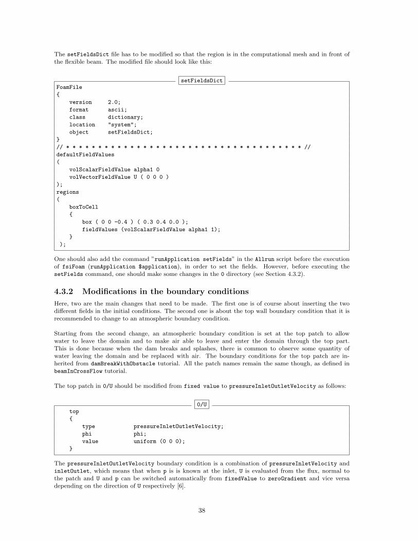
The setFieldsDict file has to be modified so that the region is in the computational mesh and in front ofthe flexible beam. The modified file should look like this:
setFieldsDictFoamFile
{
version 2.0;
format ascii;
class dictionary;
location "system";
object setFieldsDict;
}
// * * * * * * * * * * * * * * * * * * * * * * * * * * * * * * * * * * * * * //
defaultFieldValues
(
volScalarFieldValue alpha1 0
volVectorFieldValue U ( 0 0 0 )
);
regions
(
boxToCell
{
box ( 0 0 -0.4 ) ( 0.3 0.4 0.0 );
fieldValues (volScalarFieldValue alpha1 1);
}
);
One should also add the command ”runApplication setFields” in the Allrun script before the executionof fsiFoam (runApplication $application), in order to set the fields. However, before executing thesetFields command, one should make some changes in the 0 directory (see Section 4.3.2).
4.3.2 Modifications in the boundary conditions
Here, two are the main changes that need to be made. The first one is of course about inserting the twodifferent fields in the initial conditions. The second one is about the top wall boundary condition that it isrecommended to change to an atmospheric boundary condition.
Starting from the second change, an atmospheric boundary condition is set at the top patch to allowwater to leave the domain and to make air able to leave and enter the domain through the top part.This is done because when the dam breaks and splashes, there is common to observe some quantity ofwater leaving the domain and be replaced with air. The boundary conditions for the top patch are in-herited from damBreakWithObstacle tutorial. All the patch names remain the same though, as defined inbeamInCrossFlow tutorial.
The top patch in 0/U should be modified from fixed value to pressureInletOutletVelocity as follows:
0/Utop
{
type pressureInletOutletVelocity;
phi phi;
value uniform (0 0 0);
}
The pressureInletOutletVelocity boundary condition is a combination of pressureInletVelocity andinletOutlet, which means that when p is is known at the inlet, U is evaluated from the flux, normal tothe patch and U and p can be switched automatically from fixedValue to zeroGradient and vice versadepending on the direction of U respectively [6].
38
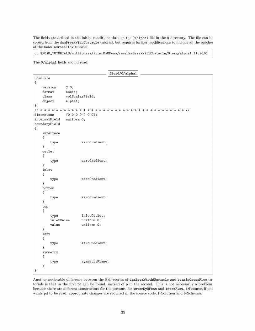
The fields are defined in the initial conditions through the 0/alpha1 file in the 0 directory. The file can becopied from the damBreakWithObstacle tutorial, but requires further modifications to include all the patchesof the beamInCrossFlow tutorial.
cp $FOAM_TUTORIALS/multiphase/interDyMFoam/ras/damBreakWithObstacle/0.org/alpha1 fluid/0
The 0/alpha1 fields should read:
fluid/0/alpha1
FoamFile
{
version 2.0;
format ascii;
class volScalarField;
object alpha1;
}
// * * * * * * * * * * * * * * * * * * * * * * * * * * * * * * * * * * * * * //
dimensions [0 0 0 0 0 0 0];
internalField uniform 0;
boundaryField
{
interface
{
type zeroGradient;
}
outlet
{
type zeroGradient;
}
inlet
{
type zeroGradient;
}
bottom
{
type zeroGradient;
}
top
{
type inletOutlet;
inletValue uniform 0;
value uniform 0;
}
left
{
type zeroGradient;
}
symmetry
{
type symmetryPlane;
}
}
Another noticeable difference between the 0 diretories of damBreakWithObstacle and beamInCrossFlow tu-torials is that in the first pd can be found, instead of p in the second. This is not necessarily a problem,because there are different constructors for the pressure for interDyMFoam and interFlow. Of course, if onewants pd to be read, appropriate changes are required in the source code, fvSolution and fvSchemes.
39
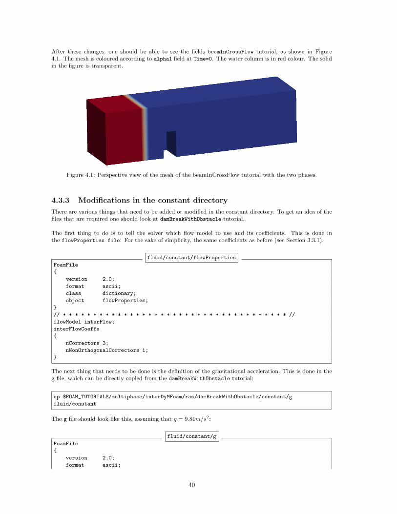
After these changes, one should be able to see the fields beamInCrossFlow tutorial, as shown in Figure4.1. The mesh is coloured according to alpha1 field at Time=0. The water column is in red colour. The solidin the figure is transparent.
Figure 4.1: Perspective view of the mesh of the beamInCrossFlow tutorial with the two phases.
4.3.3 Modifications in the constant directory
There are various things that need to be added or modified in the constant directory. To get an idea of thefiles that are required one should look at damBreakWithObstacle tutorial.
The first thing to do is to tell the solver which flow model to use and its coefficients. This is done inthe flowProperties file. For the sake of simplicity, the same coefficients as before (see Section 3.3.1).
fluid/constant/flowProperties
FoamFile
{
version 2.0;
format ascii;
class dictionary;
object flowProperties;
}
// * * * * * * * * * * * * * * * * * * * * * * * * * * * * * * * * * * * * * //
flowModel interFlow;
interFlowCoeffs
{
nCorrectors 3;
nNonOrthogonalCorrectors 1;
}
The next thing that needs to be done is the definition of the gravitational acceleration. This is done in theg file, which can be directly copied from the damBreakWithObstacle tutorial:
cp $FOAM_TUTORIALS/multiphase/interDyMFoam/ras/damBreakWithObstacle/constant/g
fluid/constant
The g file should look like this, assuming that g = 9.81m/s2:
fluid/constant/g
FoamFile
{
version 2.0;
format ascii;
40
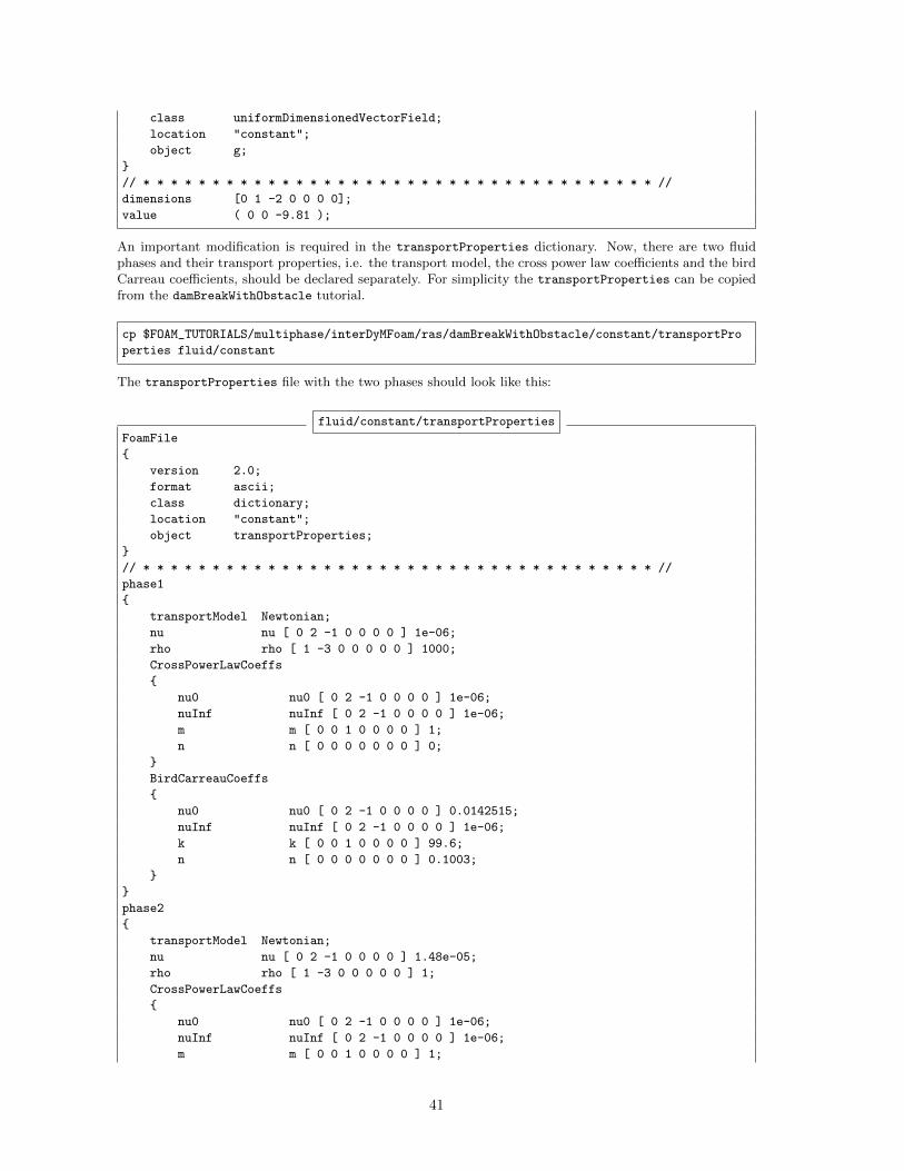
class uniformDimensionedVectorField;
location "constant";
object g;
}
// * * * * * * * * * * * * * * * * * * * * * * * * * * * * * * * * * * * * * //
dimensions [0 1 -2 0 0 0 0];
value ( 0 0 -9.81 );
An important modification is required in the transportProperties dictionary. Now, there are two fluidphases and their transport properties, i.e. the transport model, the cross power law coefficients and the birdCarreau coefficients, should be declared separately. For simplicity the transportProperties can be copiedfrom the damBreakWithObstacle tutorial.
cp $FOAM_TUTORIALS/multiphase/interDyMFoam/ras/damBreakWithObstacle/constant/transportPro
perties fluid/constant
The transportProperties file with the two phases should look like this:
fluid/constant/transportProperties
FoamFile
{
version 2.0;
format ascii;
class dictionary;
location "constant";
object transportProperties;
}
// * * * * * * * * * * * * * * * * * * * * * * * * * * * * * * * * * * * * * //
phase1
{
transportModel Newtonian;
nu nu [ 0 2 -1 0 0 0 0 ] 1e-06;
rho rho [ 1 -3 0 0 0 0 0 ] 1000;
CrossPowerLawCoeffs
{
nu0 nu0 [ 0 2 -1 0 0 0 0 ] 1e-06;
nuInf nuInf [ 0 2 -1 0 0 0 0 ] 1e-06;
m m [ 0 0 1 0 0 0 0 ] 1;
n n [ 0 0 0 0 0 0 0 ] 0;
}
BirdCarreauCoeffs
{
nu0 nu0 [ 0 2 -1 0 0 0 0 ] 0.0142515;
nuInf nuInf [ 0 2 -1 0 0 0 0 ] 1e-06;
k k [ 0 0 1 0 0 0 0 ] 99.6;
n n [ 0 0 0 0 0 0 0 ] 0.1003;
}
}
phase2
{
transportModel Newtonian;
nu nu [ 0 2 -1 0 0 0 0 ] 1.48e-05;
rho rho [ 1 -3 0 0 0 0 0 ] 1;
CrossPowerLawCoeffs
{
nu0 nu0 [ 0 2 -1 0 0 0 0 ] 1e-06;
nuInf nuInf [ 0 2 -1 0 0 0 0 ] 1e-06;
m m [ 0 0 1 0 0 0 0 ] 1;
41
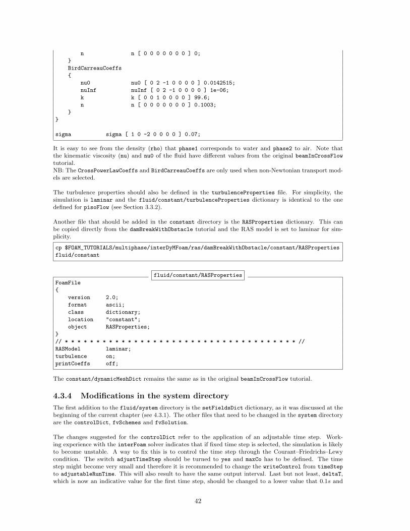
n n [ 0 0 0 0 0 0 0 ] 0;
}
BirdCarreauCoeffs
{
nu0 nu0 [ 0 2 -1 0 0 0 0 ] 0.0142515;
nuInf nuInf [ 0 2 -1 0 0 0 0 ] 1e-06;
k k [ 0 0 1 0 0 0 0 ] 99.6;
n n [ 0 0 0 0 0 0 0 ] 0.1003;
}
}
sigma sigma [ 1 0 -2 0 0 0 0 ] 0.07;
It is easy to see from the density (rho) that phase1 corresponds to water and phase2 to air. Note thatthe kinematic viscosity (nu) and nu0 of the fluid have different values from the original beamInCrossFlowtutorial.NB: The CrossPowerLawCoeffs and BirdCarreauCoeffs are only used when non-Newtonian transport mod-els are selected.
The turbulence properties should also be defined in the turbulenceProperties file. For simplicity, thesimulation is laminar and the fluid/constant/turbulenceProperties dictionary is identical to the onedefined for pisoFlow (see Section 3.3.2).
Another file that should be added in the constant directory is the RASProperties dictionary. This canbe copied directly from the damBreakWithObstacle tutorial and the RAS model is set to laminar for sim-plicity.
cp $FOAM_TUTORIALS/multiphase/interDyMFoam/ras/damBreakWithObstacle/constant/RASProperties
fluid/constant
fluid/constant/RASProperties
FoamFile
{
version 2.0;
format ascii;
class dictionary;
location "constant";
object RASProperties;
}
// * * * * * * * * * * * * * * * * * * * * * * * * * * * * * * * * * * * * * //
RASModel laminar;
turbulence on;
printCoeffs off;
The constant/dynamicMeshDict remains the same as in the original beamInCrossFlow tutorial.
4.3.4 Modifications in the system directory
The first addition to the fluid/system directory is the setFieldsDict dictionary, as it was discussed at thebeginning of the current chapter (see 4.3.1). The other files that need to be changed in the system directoryare the controlDict, fvSchemes and fvSolution.
The changes suggested for the controlDict refer to the application of an adjustable time step. Work-ing experience with the interFoam solver indicates that if fixed time step is selected, the simulation is likelyto become unstable. A way to fix this is to control the time step through the Courant–Friedrichs–Lewycondition. The switch adjustTimeStep should be turned to yes and maxCo has to be defined. The timestep might become very small and therefore it is recommended to change the writeControl from timeStep
to adjustableRunTime. This will also result to have the same output interval. Last but not least, deltaT,which is now an indicative value for the first time step, should be changed to a lower value that 0.1s and
42
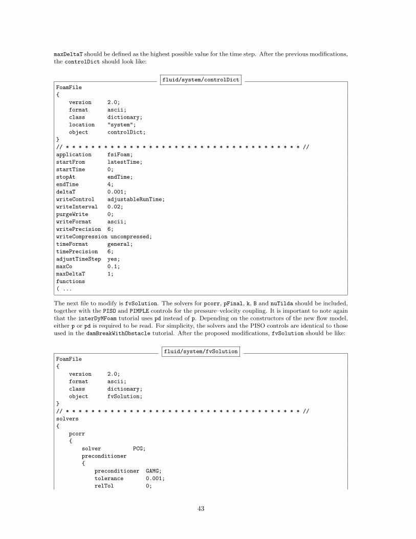
maxDeltaT should be defined as the highest possible value for the time step. After the previous modifications,the controlDict should look like:
fluid/system/controlDict
FoamFile
{
version 2.0;
format ascii;
class dictionary;
location "system";
object controlDict;
}
// * * * * * * * * * * * * * * * * * * * * * * * * * * * * * * * * * * * * * //
application fsiFoam;
startFrom latestTime;
startTime 0;
stopAt endTime;
endTime 4;
deltaT 0.001;
writeControl adjustableRunTime;
writeInterval 0.02;
purgeWrite 0;
writeFormat ascii;
writePrecision 6;
writeCompression uncompressed;
timeFormat general;
timePrecision 6;
adjustTimeStep yes;
maxCo 0.1;
maxDeltaT 1;
functions
( ...
The next file to modify is fvSolution. The solvers for pcorr, pFinal, k, B and nuTilda should be included,together with the PISO and PIMPLE controls for the pressure–velocity coupling. It is important to note againthat the interDyMFoam tutorial uses pd instead of p. Depending on the constructors of the new flow model,either p or pd is required to be read. For simplicity, the solvers and the PISO controls are identical to thoseused in the damBreakWithObstacle tutorial. After the proposed modifications, fvSolution should be like:
fluid/system/fvSolution
FoamFile
{
version 2.0;
format ascii;
class dictionary;
object fvSolution;
}
// * * * * * * * * * * * * * * * * * * * * * * * * * * * * * * * * * * * * * //
solvers
{
pcorr
{
solver PCG;
preconditioner
{
preconditioner GAMG;
tolerance 0.001;
relTol 0;
43
smoother GaussSeidel;
nPreSweeps 0;
nPostSweeps 2;
nBottomSweeps 2;
cacheAgglomeration false;
nCellsInCoarsestLevel 10;
agglomerator faceAreaPair;
mergeLevels 1;
}
tolerance 0.0001;
relTol 0;
maxIter 100;
}
p
{
solver GAMG;
tolerance 1e-06;
relTol 0;
minIter 1;
maxIter 1000;
smoother GaussSeidel;
nPreSweeps 0;
nPostSweeps 2;
nFinestSweeps 2;
scaleCorrection true;
directSolveCoarsest false;
cacheAgglomeration true;
nCellsInCoarsestLevel 20;
agglomerator faceAreaPair;
mergeLevels 1;
}
pFinal
{
solver PCG;
preconditioner
{
preconditioner GAMG;
tolerance 1e-08;
relTol 0;
nVcycles 2;
smoother GaussSeidel;
nPreSweeps 0;
nPostSweeps 2;
nFinestSweeps 2;
cacheAgglomeration false;
nCellsInCoarsestLevel 10;
agglomerator faceAreaPair;
mergeLevels 1;
}
tolerance 1e-08;
relTol 0;
maxIter 20;
}
cellMotionU
{
solver GAMG;
tolerance 1e-06;
relTol 0.001;
minIter 1;
44
maxIter 100;
smoother GaussSeidel;
nPreSweeps 0;
nPostSweeps 2;
nFinestSweeps 2;
scaleCorrection true;
directSolveCoarsest false;
cacheAgglomeration true;
nCellsInCoarsestLevel 20;
agglomerator faceAreaPair;
mergeLevels 1;
}
U
{
solver PBiCG;
preconditioner DILU;
tolerance 1e-06;
relTol 0;
minIter 1;
}
k
{
solver PBiCG;
preconditioner DILU;
tolerance 1e-08;
relTol 0;
}
B
{
solver PBiCG;
preconditioner DILU;
tolerance 1e-08;
relTol 0;
}
nuTilda
{
solver PBiCG;
preconditioner DILU;
tolerance 1e-08;
relTol 0;
}
}
PISO
{
cAlpha 1;
}
PIMPLE
{
momentumPredictor yes;
nOuterCorrectors 1;
nCorrectors 4;
nNonOrthogonalCorrectors 0;
nAlphaCorr 1;
nAlphaSubCycles 3;
cAlpha 1;
pRefPoint (0.51 0.51 0.51);
pRefValue 0;
}
45

The last file to modify is fvSchemes. Once again, a comparison between the two tutorials (using the programkompare) will reveal the additions required. The main change is that the field alpha1 has been introduced, to-gether with rho*phi (see the new constructors at Section 4.2.2.1). This affects the gradSchemes, divSchemesand the fluxRequired. After the necessary modifications the fvSchemes dictionary should read in whole:
fluid/system/fvSchemes
FoamFile
{
version 2.0;
format ascii;
class dictionary;
object fvSchemes;
}
// * * * * * * * * * * * * * * * * * * * * * * * * * * * * * * * * * * * * * //
ddtSchemes
{
default Euler;
}
gradSchemes
{
default Gauss linear;
grad(U) Gauss linear;
grad(alpha) Gauss linear;
}
divSchemes
{
default none;
div(phi,U) Gauss linear;
div(rho*phi,U) Gauss upwind;
div(phi,alpha) Gauss vanLeer;
div(phirb,alpha) Gauss interfaceCompression;
}
laplacianSchemes
{
default none;
laplacian(nu,U) Gauss linear skewCorrected 1;
laplacian((1|A(U)),p) Gauss linear skewCorrected 1;
laplacian(diffusivity,cellMotionU) Gauss linear skewCorrected 1;
}
interpolationSchemes
{
default linear;
interpolate(y) linear;
interpolate(U) skewCorrected linear;
}
snGradSchemes
{
default skewCorrected 1;
}
fluxRequired
{
default no;
p;
pcorr;
alpha;
}
Of course, if pd is used instead of p, appropriate changes should be made.
46
Chapter 5
Conclusions and future work
This work showed a detailed presentation of the new FSI package created for foam-extend-3.1. As it hasbeen discussed, the FSI package is still under development and it is expected to be included in main dis-tribution of foam-extend. In this case, there is a chance that substantial changes to the structure of thepackage will take place. Therefore, any future users of the FSI package that want to consult this documentshould be aware of the changes made after the present date.
Future work should be carried out to complete the modifications required in the interFlow package tomake it functional. Future tutorials should include other classic problems like free surface current and waveloading on a beam. This requires implementation of new boundary conditions in the FSI package thatwill expand its applicability. Boundary conditions for waves and currents can be found in the packageswaves2Foam [4] and IHFOAM [2].
47

48
Bibliography
[1] Robert L. Campbell (2010): Fluid-Structure Interaction and inverse design simulations for flexible tur-bomachinery, PhD Thesis, Pennsylvania State University, College of Engineering
[2] Pablo Higuera and Javier L. Lara and Inigo J. Losada (2013): Realistic wave generation and activewave absorption for Navier Stokes models: Application to OpenFOAM, Coastal Engineering, Volume71, Pages 102 - 118
[3] Hua-Dong Yao: Simulation of Fluid-Structural Interaction using OpenFOAM, Presentation (2014)http://www.tfd.chalmers.se/~hani/kurser/OS_CFD/OFLecFSI-1.pdf
[4] Jacobsen, N G and Fuhrman, D R and Fredse, J (2014): A Wave Generation Toolbox for the Open-SourceCFD Library: OpenFoam®, Int. J. Numerl. Meth. Fluids, Volume 70, Pages 1073-1088
[5] C. Michler, S.J. Hulshoff, E.H. van Brummelen, R. de Borst (2003): A monolithic approach to fluid-structure interaction, Preprint submitted to Elsevier Science, 25 March 2003
[6] OpenFOAM Foundation (2012): OpenFOAM, The Open Source CFD Toolbox User Guide, Version 2.1.1,16 May 2012
[7] Zeljko Tukovic: FVM for FSI with large structural displacements, Presentation (2009)http://www.tfd.chalmers.se/~hani/kurser/OS_CFD_2009/FSIslides.pdf
49