Embed Size (px)
Citation preview
CFE Generator Protection Guidelines for Setting 40 and 64G Elements Based on
Simulations and Field Experience
Mauricio Sosa-Aguiluz Comisión Federal de Electricidad
Armando Guzmán and Jean León Schweitzer Engineering Laboratories, Inc.
© 2015 IEEE. Personal use of this material is permitted. Permission from IEEE must be obtained for all other uses, in any current or future media, including reprinting/republishing this material for advertising or promotional purposes, creating new collective works, for resale or redistribution to servers or lists, or reuse of any copyrighted component of this work in other works.
This paper was presented at the 68th Annual Conference for Protective Relay Engineers and can be accessed at: http://dx.doi.org/10.1109/CPRE.2015.7102182.
For the complete history of this paper, refer to the next page.

Published in the proceedings of the 69th Annual Georgia Tech Protective Relaying Conference as an alternate
Atlanta, Georgia April 29–May 1, 2015
Previously presented at the 68th Annual Conference for Protective Relay Engineers, March 2015
Previous revised edition released October 2014
Originally presented at the 41st Annual Western Protective Relay Conference, October 2014

1
CFE Generator Protection Guidelines for Setting 40 and 64G Elements Based on
Simulations and Field Experience Mauricio Sosa-Aguiluz, Comisión Federal de Electricidad
Armando Guzmán and Jean León, Schweitzer Engineering Laboratories, Inc.
Abstract—This paper presents guidelines developed by Comisión Federal de Electricidad, the national utility of Mexico, to improve and standardize generator protection through a better understanding of generator protection performance during normal operation and fault conditions. Based on the results of simulations and field experiences, we propose setting guidelines and improved protection schemes for loss-of-field (40) and stator ground fault (64G) protection that take advantage of the flexibility of multifunction generator protection relays.
I. INTRODUCTION The first version of the Comisión Federal de Electricidad
(CFE) generator protection setting guide was released in 2011 and applied to generators and generator groups, including main and auxiliary transformers [1]. The overall results of applying the guide show that primary equipment damage has been minimized. However, CFE found some challenges when applying the guide because of the limitations of older protective relays. This paper presents improvements to the original setting guide based on the lessons learned when applying the guide to multiple generator protection schemes.
CFE simulated loss-of-field conditions and stator ground faults and validated these simulations using field events [2]. Based on the results of these simulations and field experiences, we propose setting guidelines and improved protection schemes for loss-of-field (40) and stator ground fault (64G) protection that take advantage of the flexibility of multifunction generator protection relays. The proposed settings and schemes improve the performance of traditional generator protection as follows:
• The operating characteristic of the Zone 2 mho loss-of-field element is set according to the capability curve of the generator to better detect undesired generator operating conditions.
• The operating time of the Zone 2 mho loss-of-field element decreases for low positive-sequence voltage or high current level at the generator terminals.
• The 64G element includes logic to detect intermittent faults, as well as logic to speed up the 64G when the breaker between the generator and the step-up transformer is open.
• Dedicated logic reduces the operating time of the 64G element when the zero-sequence voltage magnitude is greater than 0.07 per unit (pu) and the negative-sequence voltage magnitude is less than 0.05 pu.
We share CFE experiences of applying the proposed guidelines to an installed base of 175 generating units. The paper also demonstrates how field event records provide information to analyze and improve the performance of generator protection.
II. CFE POWER PLANT INSTALLATIONS CFE, the Mexican electrical utility, is in charge of the
generation, transmission, and distribution of electrical energy to more than 37.8 million customers and a population of 118 million people. CFE covers all of the Mexican territory and has a growth of one million customers every year, with the mission of providing electricity for the progress of Mexico. The utility was created in 1937 and has over 75,000 employees. CFE owns 868,000 kilometers of transmission and distribution lines as well as 451 generating units that are part of 131 power plants with several types of energy sources (hydroelectric, oil, coal, dual, geothermal, gas, diesel, wind, solar, and nuclear), for a total of 40,568.3 MW of installed capacity. Fig. 1 shows the geographical locations of some of these power plants. CFE also receives energy from independent power producers (IPPs). IPP generation consists of 453 generating units located in 28 power plants (mainly plants with combined generation cycles and wind farms), for a total installed capacity of 12,850 MW.
Coal
Combined Cycle
DieselDualWind
GeothermalHydroelectric
Petroleum
Gas
Fig. 1. Types of power plants in Mexico, excluding nuclear generation.
CFE installations include turbines, generators, transformers, protective relays, excitation controls, and auxiliary systems from different manufacturers with vintage

2
and modern technology. Because of the equipment diversity, CFE needs to standardize its generator protection schemes. Additionally, CFE has access to information about power system disturbances, equipment faults, and other failure events and uses this information to improve protective relaying practices.
Since 2009, CFE protection engineers have been working to standardize generator protection practices to increase the life of their generators [1]. Up to now, the recommendations of the guide have been implemented on 175 units, with capacities that vary from 5 to 350 MW.
CFE owns several old machines that are protected with electromechanical or analog electronic relays, and CFE realized that protection personnel cannot implement several of the requirements of the guide using this technology. On the other hand, these requirements can be implemented using the functionality and programmability available in microprocessor-based relays.
A. Generator Connections to the Power System
1) Direct Connection to the Network In this power plant layout, the generators are connected to
the distribution network directly without a power transformer. The generators are connected to the load bus to feed auxiliary services and local loads (see Fig. 2).
G LoadLoadGenerator (G) Auxiliary Load
Load Bus
Power System
Fig. 2. Direct generator connection to the distribution network.
2) Connection Through a Step-Up Transformer This is the typical connection for most CFE installations,
where the generator is connected with a single step-up transformer (see Fig. 3). There are very few exceptions where two or more machines are connected to a single transformer or where very small generators are connected to distribution network or loads.
G
Generator Auxiliary Load
Power System
Generator Step-Up Transformer (GSU)
Fig. 3. Typical connection of most CFE generators with a step-up transformer.
B. Types of Generator Grounding
1) Ungrounded Neutral An ungrounded generator does not have a connection
between its neutral and ground. However, it still has phase-to-ground capacitance because of the generator winding, transformer winding, bus, cable, and auxiliary transformer capacitances. For this type of system, ground faults are limited to very low current values that depend on the phase-to-ground capacitance. Phase-to-ground faults cause full neutral voltage displacement, and the voltage of the unfaulted phases rises to phase-to-phase voltage levels. Ungrounded systems need to be insulated for full phase-to-phase voltage levels. These installations are not common in Mexico; therefore, they are not covered by the CFE guide.
2) Solid Grounding A solid connection to ground limits the voltage rise on the
unfaulted phases for phase-to-ground faults. The ground fault current is limited only by the generator impedance. Because generator zero-sequence impedance is normally low, high ground fault currents are common. Additionally, even if protective relays trip fast, fault currents are present for several seconds, causing major machine damage. This connection is usually limited to low-capacity generator applications and is not covered by the CFE guide.
3) Low-Impedance Grounding In this type of grounding, the generator neutral is
connected to ground through a resistor or reactor to limit the generator ground fault contribution to values close to 150 percent of the generator nominal current. It is commonly used in industrial systems where several generators are connected to a common bus and loads without transformers, providing ground source to the system (see Fig. 2). It is not used in CFE power plants and is not covered by the CFE guide.
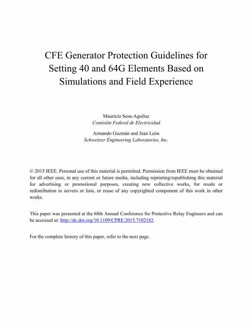
4) High-Impedance Grounding Fig. 4 depicts a generator neutral connected to ground
through a transformer (commonly a distribution transformer) with a resistor connected to its secondary winding. The grounding resistor can be an inexpensive low-voltage, low-resistance resistor because its value reflects to the primary side of the transformer multiplied by the square of the transformer turn ratio. The resistor and transformer are chosen to limit phase-to-ground fault currents to values between 2 and 15 A to minimize generator damage. The ground fault current magnitudes are similar or slightly greater than the magnitudes of the generator winding phase-to-ground capacitance currents to avoid overvoltages. This is the most common generator grounding in CFE installations, and it is the only type of grounding covered in the CFE guide.
3
Grounding Transformer and Resistor
Generator Windings
Fig. 4. High-impedance generator grounding.
III. LOSS OF EXCITATION Originally, generator protection focused mainly on
protecting the armature winding of the machine without paying much attention to loss-of-field effects on the machine and on the power system. Crossman, Lindemuth, and Webb pointed out the need to disconnect the machine for loss-of-field conditions to avoid system disturbances and machine damage [3]. In this section of the paper, we focus our discussion on the protection of turbogenerators to avoid generator damage due to partial or complete loss of field.
A. Generator Stress Caused by Loss of Excitation Internal short circuits in a section of the field winding can
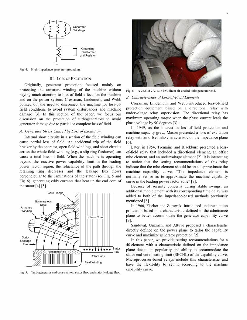
cause partial loss of field. An accidental trip of the field breaker by the operator, open field windings, and short circuits across the whole field winding (e.g., a slip-ring flashover) can cause a total loss of field. When the machine is operating beyond the reactive power capability limit in the leading power factor region, the reluctance of the path through the retaining ring decreases and the leakage flux flows perpendicular to the laminations of the stator (see Fig. 5 and Fig. 6), generating eddy currents that heat up the end core of the stator [4] [5].
Armature Winding
Nonmagnetic Steel
Core Flange
Rotor Body
Stator FluxRetaining Ring
Stator Leakage
Flux
Field Winding
Stator Core
Fig. 5. Turbogenerator end construction, stator flux, and stator leakage flux.
Fig. 6. A 26.6 MVA, 13.8 kV, direct air-cooled turbogenerator end.
B. Characteristics of Loss-of-Field Elements Crossman, Lindemuth, and Webb introduced loss-of-field
protection equipment based on a directional relay with undervoltage relay supervision. The directional relay has maximum operating torque when the phase current leads the phase voltage by 90 degrees [3].
In 1949, as the interest in loss-of-field protection and machine capacity grew, Mason presented a loss-of-excitation relay with an offset mho characteristic on the impedance plane [6].
Later, in 1954, Tremaine and Blackburn presented a loss-of-field relay that included a directional element, an offset mho element, and an undervoltage element [7]. It is interesting to notice that the setting recommendations of this relay indicate that the mho element should be set to approximate the machine capability curve: “The impedance element is normally set so as to approximate the machine capability curve in the leading power factor zone” [7].
Because of security concerns during stable swings, an additional mho element with its corresponding time delay was added to both of the impedance-based methods previously mentioned [8].
In 1966, Fischer and Zurowski introduced underexcitation protection based on a characteristic defined in the admittance plane to better accommodate the generator capability curve [9].
Sandoval, Guzmán, and Altuve proposed a characteristic directly defined on the power plane to tailor the capability curve and maximize generator protection [2].
In this paper, we provide setting recommendations for a 40 element with a characteristic defined on the impedance plane due to its popularity and ability to accommodate the stator end-core heating limit (SECHL) of the capability curve. Microprocessor-based relays include this characteristic and have the flexibility to set it according to the machine capability curve.

4
Of the vintage impedance-based elements, the element proposed by Tremaine and Blackburn is the one that can be set closer to the generator SECHL. Fig. 7 shows the characteristics of this element and its traditionally recommended settings [10]. The system impedance Xsys includes the step-up transformer impedance plus the system equivalent impedance. Zone 1 includes a negative offset equal to half the nonsaturated transient direct-axis synchronous reactance dX′ . Zone 2 includes a positive offset equal to Xsys and has a diameter equal to Xsys + 1.1 • Xd, where Xd is the direct-axis synchronous reactance.
Zone 1 1.1 Xd
X
R
Zone 2
Xsys
′− dX / 2
Fig. 7. Two-zone loss-of-field protection using positive- and negative-offset mho elements supervised by a directional element.
C. Setting Recommendations of Original CFE Guide The original CFE guide provided the following setting
recommendations based on the capability curve shown in Fig. 8:
• Use a mho element characteristic with two offset mho elements, Zone 1 and Zone 2.
• Set the Zone 1 negative offset equal to dX /2′ . • Set the Zone 1 diameter equal to Xd. • Set the Zone 1 delay equal to 0.75 seconds. • Set the Zone 2 positive offset according to (1). • Set the Zone 2 diameter according to (2). • Set the Zone 2 delay equal to 5 seconds. • Set the Zone 2 delay equal to 2 seconds when the
positive-sequence voltage is less than 0.9 pu.
• Set the Zone 2 delay equal to 2 seconds when any phase current is greater than 1.1 pu.
• Set the directional element angle according to (3).
( )
2 2
K Q2 Q1Offset
P2 Q2 Q1• Q2−
=+ −
(1)
( )
( )
2 2
2 2
K Q2 Q1 P2Diameter
Q1 Q1• Q2 P2 Q2
− + =− −
(2)
Q2Angle atanP2
=
(3)
Notice that the recommendation to set the diameter and offset of Zone 1 is similar to the settings proposed in [8] but with the diameter set to Xd instead of 1 pu. Appendix A describes the derivations of (1) and (2) and defines K. Fig. 8 shows how to obtain the values of P2, Q1, and Q2 used in (1), (2), and (3) from the capability curve. P2 is in megawatts (MW), and Q1 and Q2 are in megavolt-ampere reactive (MVAR).
–50 0 50 100 150 200 250–150
–100
–50
0
50
100
150
MW
MV
AR
0
0
0
(P1,Q1)
(P2,Q2)
Fig. 8. P and Q reference points to calculate Zone 2 and directional element settings based on the capability curve with maximum power output.
Notice that the offset of Zone 2 is independent of Xsys. Therefore, it is not affected by changes in the network topology.

5
D. Field Experience CFE experienced two undesired generator trips during
routine black start and minimum excitation limiter (MEL) tests. The generator trip during the black start test was caused by human error, and the misoperation of the 40 element during the MEL test was caused by lack of margin between the MEL and Zone 2 characteristics.
1) Generator Trip During Black Start Testing One of the generators of the Mérida II power plant tripped
during black start testing as a result of power oscillations while the operator was increasing power output with the automatic voltage regulator (AVR) inadvertently operating in manual control. Fig. 9 shows the basic automatic and manual excitation controls of the excitation system of the generator that was involved in the black start procedure. Appendix B includes data about the generator, excitation system, and power system and the settings of the 40 element.
52
System
Automatic Channel
Manual Channel
Excitation Transformer
Pulse Generator
Pulse Amplifier
Excitation System Bridge
Vdc
Adc
Initial Excitation
Field Breaker
AC Breaker
Fig. 9. Basic components of the static AVR control.
When the AVR is operating in manual control, the excitation voltage remains constant if the operator does not change its field current. Under these conditions, the excitation voltage magnitude corresponds to the voltage magnitude at the time when the machine was synchronized to the power system. This voltage magnitude limits the maximum power output of the machine. If the power output increases without increasing the field current, the machine will reach its steady-state stability limit (SSSL) and will start oscillating. When the AVR is in manual control, the MEL activation cannot prevent
dangerous volt-ampere reactive (VAR) flow into the machine. The 40 element can detect this undesired operating condition and trip the generator.
Fig. 10 shows the current and voltage oscillations of the machine when the SSSL was exceeded while the operator was increasing the machine power output with the AVR inadvertently operating in manual control. The power oscillations continue until Zone 2 of the 40 element operates and the generator and field breakers open, avoiding machine damage.
Fig. 10. Current and voltage oscillations and operation of the 40 element to avoid generator damage.
Fig. 11 and Fig. 12 depict the system oscillation trajectories on the power and impedance planes, respectively, as well as the MEL characteristic and the characteristics of Zone 1 and Zone 2 of the 40 element. Fig. 12 shows how the operating point enters these characteristics and remains there until the Zone 2 time expires and the generator breaker trips. The characteristic of Zone 2 was set according to (1), (2), and (3).
–10 0 10 20 30 40 50 60–30
–20
–10
0
10
20
30
40
MW
MV
AR
0
0
0
MEL
Capability Curve
Fig. 11. Power oscillations and operating point entering the MEL operating region on the power plane.

6
–20 –10 0 10 20–30
–20
–10
0
10
Real (secondary ohms)
Imag
inar
y (s
econ
dary
ohm
s )
Zone 1 Zone 2 Directional Element
Fig. 12. Power oscillations and operating point entering the Zone 1 and Zone 2 operating regions on the impedance plane.
2) Generator Trip During MEL Testing CFE routinely performs AVR tests at different power
loading levels of its generators to verify that all AVR functionality is working correctly. According to CFE maintenance practices, AVRs should be tested at least every two years. These tests include the verification of the MEL at different loading levels. To perform the MEL test, the power plant operator lowers the terminal voltage by varying the AVR voltage reference for the generator to absorb reactive power until the MEL operates.
CFE tested the AVR of one of the generators at the Mérida II power plant. Appendix C shows data about the generator, excitation system, power system, and relay settings.
Tests were performed at 50 and 90 percent loading. While performing the 90 percent loading test (which corresponds to 75 MW), the unit was disconnected from the power system because of the operation of Zone 2 of the 40 element. The settings of this element corresponded to the original CFE setting guide [1].
Fig. 13 shows the MEL assertion for a voltage equal to 0.95 pu of the 13.8 kV nominal voltage of the machine. Fig. 14 shows the trip of the generator due to the 40 element operation.
Fig. 13. MEL operation while testing the generator at 90 percent loading.
Fig. 14. Operation of Zone 2 of the 40 element, causing an undesired trip.

7
Fig. 15 and Fig. 16 show the operating point for the event on the power and impedance planes, respectively. The blue dots correspond to the initial assertion of the MEL, and the red dots correspond to the trip event.
0 20 40 60 80 100–80
–60
–40
–20
0
20
40
60
80
MW
MV
AR
MELZone 1Zone 2Capability Curve
Fig. 15. The operating point enters the operating region of Zone 2, causing an undesired generator trip (as illustrated on the power plane).
–30 –20 –10 0 10 20 30–50
–40
–30
–20
–10
0
10
20
30
Real (secondary ohms)
Imag
inar
y (s
econ
dary
ohm
s)
MELZone 1Zone 2
Capability CurveDirectional Element
Fig. 16. The operating point enters the operating region of Zone 2, causing an undesired generator trip (as illustrated on the impedance plane).
Notice that the representation of the relay characteristics on the power plane according to (4) uses the magnitude of the positive-sequence operating voltage |V1| and not the nominal voltage magnitude. In (4), Z1 is the positive-sequence impedance of the characteristic in primary ohms, V1 is in primary volts, and the complex power S is expressed in megavolt amperes. Because of the reduced voltage, the pre-existing margin between the MEL and the Zone 2 element characteristics disappears, causing the incursion of the operating point into the Zone 2 characteristic.
2
6*
V1
2 1S 310Z1
=
(4)
E. New Setting Recommendation Typically, CFE sets the MEL characteristic between 90 and
95 percent of the machine reactive capability in the underexcited region. In order to increase the margin between the MEL and Zone 2 characteristics in these typical applications, CFE increased the Q1, P2, and Q2 values by 110 percent and recalculated the settings using (1), (2), and (3). With this additional margin, the generator rides through the MEL tests without 40 element misoperation, as Fig. 17 and Fig. 18 illustrate. When the MEL characteristic is set to 80 percent or less of the machine reactive capability, CFE uses the original values of Q1, P2, and Q2 to calculate the Zone 2 settings of the 40 element.
0 20 40 60 80 100–80
–60
–40
–20
0
20
40
60
80
MW
MV
AR
MELZone 1Zone 2Capability Curve
Fig. 17. The operating point enters the MEL operating region but does not enter the Zone 2 operating region, avoiding an undesired generator trip (as illustrated on the power plane).

8
–30 –20 –10 0 10 20 30–50
–40
–30
–20
–10
0
10
20
30
Real (secondary ohms)
Imag
inar
y (s
econ
dary
ohm
s)
MELZone 1Zone 2
Capability CurveDirectional Element
Fig. 18. The operating point enters the MEL operating region but does not enter the Zone 2 operating region, avoiding an undesired generator trip (as illustrated on the impedance plane).
IV. STATOR GROUND FAULT PROTECTION Stator ground fault protection depends on the type of
generator grounding. As Section II describes, most CFE machines use high-impedance grounding; hence, the CFE guide focuses on the protection of generators with this type of grounding. In these applications, there are four major methods for stator ground fault protection: neutral fundamental frequency overvoltage, neutral third-harmonic undervoltage, third-harmonic differential, and current injection. In this paper, we focus on CFE proposed improvements for neutral fundamental frequency overvoltage element settings (64G).
A. Generator Stress Caused by Stator Ground Faults The goal of high-impedance grounding is to minimize core
and winding damage to the generator by limiting ground fault currents to values below its thermal and mechanical limits. These values are typically between 2 and 15 primary amperes. Because the fault current is limited to very low values, it was common practice in the past to use neutral fundamental frequency overvoltage relays to alert operators about the occurrence of a stator ground fault so they could shut down the machine manually. This practice is not recommended today, and most utilities choose to trip because of the increased risk of the occurrence of a second ground fault. The second ground fault causes very high currents and major generator damage. The probability of a second ground fault increases after the first one because the voltage on the healthy phases increases to values close to phase-to-phase nominal voltages. In addition, the arc restrike of intermittent faults produces high overvoltages in the healthy phases that stress the winding insulation [11].
Generators are designed to withstand overvoltage conditions during phase-to-ground faults. However, any weak insulation condition that does not evolve to a ground fault at normal operating voltage may cause a fault when subject to this additional stress. These weak insulation conditions can be caused by contamination by lubrication oil, humidity, dust, and other contaminants as well as insulation degradation in older machines that are at the end of their service life.
A current differential element will detect a second ground fault on a different phase because of the high phase-to-phase fault current. A second fault on the same phase at a different winding location will also cause high current because the first ground bypasses the high-impedance grounding resistor. However, this fault will not be detected by the phase differential element because fault current will flow only between the first and second grounds and not through the protection current transformers (CTs). For these faults, the stator ground fault protection will determine the fault detection time.
In addition, transient overvoltages may increase beyond phase-to-phase nominal voltage values during arcing or intermittent fault conditions and may contribute to insulation stress and failure. Faster trip times always reduce generator damage and the risk of a second fault. The long delays required for 64G coordination for out-of-zone faults lead to increased equipment damage and a higher probability of a second fault. Furthermore, the fault current keeps flowing for some time after the relay trips until the magnetic energy stored in the generator completely decays. For generators with brushless excitation systems, this energy remains for several seconds. For generators with modern solid-state control systems, the terminal voltage and stored energy decay much faster.
Fig. 19 and Fig. 20 show the significant damage caused to a generator by a phase-to-ground fault that evolved to a phase-to-phase fault. This fault occurred before applying the protection schemes proposed in the CFE guide.
Fig. 19. Generator damage after phase-to-ground and phase-to-phase faults at different winding locations. CFE engineers in charge of fault diagnosis concluded that the fault started as a phase-to-ground fault (because of the failure pattern on the winding) and evolved to a phase-to-phase fault.

9
Fig. 20. Another view of the generator damage after phase-to-ground and phase-to-phase faults at different winding locations.
B. Neutral Overvoltage Element Fig. 21 shows a high-impedance grounded generator with
its step-up transformer and voltage transformer (VT) circuit. The figure also shows the connection of the overvoltage element (64G) in the secondary of a distribution transformer.
64G
Distribution Transformer
Generator
Generator Winding
Capacitance
VT and Fuses
Fig. 21. High-impedance grounded generator with its step-up transformer, VT circuit, and phase-to-ground capacitance.
In this installation, the fault current is limited to very low values and the voltage that appears on the generator neutral is proportional to the percentage of winding between the neutral and the fault location. The neutral voltage is close to the nominal phase-to-ground value for faults close to the terminals and close to zero for faults close to the neutral.
A sensitive overvoltage relay (64G) connected across the secondary of the grounding transformer can detect the neutral overvoltage conditions and trip for phase-to-ground faults.
With the typical setting (0.05 pu), the 64G element covers 90 to 95 percent of the generator winding. Other methods that provide additional coverage of stator winding neutral include neutral third-harmonic undervoltage, third-harmonic differential, and current injection. These methods are not covered in this paper.
Generators produce different harmonics during normal operation, including a considerable amount of zero-sequence type harmonic voltages like third and multiples of third harmonic. These triplen-harmonic voltages will appear across the overvoltage element. This element filters harmonics and responds only to fundamental quantities to obtain maximum sensitivity.
Typical neutral overvoltage elements have a delay for coordination with VT fuses to prevent generator tripping for ground faults on VTs or VT secondary circuits. This coordination requirement may lead to long tripping delays (1 to 2 seconds). Furthermore, coordination is not possible when secondary VT circuit faults cause very low currents [12].
Additionally, the neutral overvoltage element needs to be coordinated with ground fault relays beyond the high-voltage side of the step-up transformer. Even if the step-up transformer has a delta-wye connection, the capacitive coupling between the primary and secondary windings causes some zero-sequence voltage to appear at the generator terminals and neutral. This voltage is usually low because the grounding resistor impedance is much less than the impedance of the transformer interwinding capacitance. Usually this low voltage does not exceed the pickup value of the overvoltage element. Because transformer interwinding capacitance is seldom available for the protection engineer, delay is used to ensure coordination margin without knowledge of the exact neutral voltage value for external network faults.
C. Setting Recommendations and Improvements CFE generators experienced several phase-to-ground faults
that caused significant machine damage because it took a long time for the traditional protection schemes to detect these faults; some of these faults were intermittent.
We were able to analyze some of the fault event records and learn more about intermittent faults. We developed detailed models that were validated using field events. Our simulation results showed that we can improve generator protection performance by taking advantage of the flexibility of modern microprocessor-based relays.
CFE uses a neutral overvoltage element connected to the secondary of the grounding transformer to detect ground faults. Its pickup is set to 5 percent of nominal phase-to-neutral voltage with a typical delay of 0.5 seconds to coordinate with adjacent protection devices, such as VT fuses and external network relays, for out-of-zone faults.
CFE complements the described overvoltage element with three additional schemes (outlined in the following subsections) to improve the protection of the generator.

10
1) Trip Acceleration for Intermittent Faults In high-impedance grounded networks, arcing faults with
low current levels are common. The arc can be totally extinguished and reignite a few cycles later. Under these conditions, the neutral overvoltage element can pick up and drop out several times but never satisfy the required time to operate. The overvoltage element sends a trip command only when the fault becomes more prevalent or evolves to a phase-to-phase fault.
Fig. 22 shows an intermittent fault in one of the generators at the Nachi Cocom power plant during the machine startup process. The machine was unloaded at the time of the fault, and the breaker between the generator and the step-up transformer was open. The overvoltage element asserted for less than 100 milliseconds; the neutral voltage increased up to 3 kV and dropped to zero three times, showing arc extinction and restrike.
Fig. 22. Intermittent phase-to-ground fault at Nachi Cocom power plant.
The CFE guide proposes the logic depicted in Fig. 23 for faster detection of intermittent faults. If the overvoltage element deasserts, the logic opens a 5-second window that allows activating the trip command should a second assertion of this element occur with a duration longer than 3 cycles.
0
2 cyc
0
5 s 0
3 cycAND 2AND 1
64GTRIP
Fig. 23. Logic to accelerate detection of intermittent ground faults
The logic also accelerates the trip command for high-impedance arcing faults, where the neutral voltage magnitude is close to the element pickup value and the random nature of the arc causes the element to pick up and drop out.
Fig. 24 shows the generator neutral voltage and the 64G element operation for a stator ground fault. The magnitude of the neutral voltage changes between 100 and 750 V. The 64G element that is set to 462 V picked up for fewer than 5 consecutive cycles and was not able to detect the fault until it evolved to a lower resistance fault.
Fig. 24. The 64G element picks up and drops out for a high-resistance fault, and it is not able to promptly detect the fault.
It is recognized that the described logic may cause loss of coordination with VT fuses for VT or VT secondary circuit intermittent faults. Given that these VT faults are very infrequent, CFE decided to apply the logic to minimize the damage to its generators by stator ground faults.
2) Trip Acceleration Based on Sequence Voltage Magnitudes
The event report in Fig. 25 shows a ground fault at the generator bus in one CFE power plant and shows that the zero-sequence voltage magnitude is greater than the negative-sequence voltage magnitude for this fault location. The zero-sequence voltage magnitude is also greater than the negative-sequence voltage for ground faults at any point inside the generator protection zone. Appendix D explains the reason for this voltage magnitude difference in high-impedance grounded generators with delta-wye step-up transformers and why this conclusion can be generalized for any internal fault.
Fig. 25. The magnitude of the zero-sequence voltage is greater than the negative-sequence voltage magnitude for a ground fault at the generator bus.

11
On the other hand, for faults on the high side of the step-up transformer, the negative-sequence voltage magnitude is greater than the zero-sequence voltage magnitude. The event report in Fig. 26 shows an example of the faulted phase voltage and the zero- and negative-sequence voltage magnitudes for this type of fault. Appendix D explains the reason for this voltage magnitude difference and also explains why this conclusion can be generalized for any external fault.
0 0.05 0.1 0.15 0.2 0.25 0.3 0.35 0.4 0.45 0.5–20
–10
0
10
20
kV
0 0.05 0.1 0.15 0.2 0.25 0.3 0.35 0.4 0.45 0.50
0.5
1
1.5
kV
Seconds
V0V2
A-Phase Voltage
Fig. 26. The magnitude of the negative-sequence voltage is greater than the magnitude of the zero-sequence voltage for a ground fault on the high side of the step-up transformer.
The CFE guide proposes logic that uses the negative- and zero-sequence voltage magnitudes to differentiate between faults inside the generator protection zone and faults outside of this zone (see Fig. 27). This logic provides accelerated tripping for ground faults inside the generator protection zone when the zero-sequence voltage is greater than 0.07 pu and the negative-sequence voltage is less than 0.05 pu. The logic includes a delay that needs to be coordinated only with the VT fuses.
The logic in Fig. 27 is only suitable for applications where the VTs have a grounded wye-grounded wye connection, which is a common CFE practice.
0
DelayAND 1
64GTRIPV2 < 0.05 pu
V0 > 0.07 pu60 LOP
Fig. 27. Logic using negative- and zero-sequence voltage magnitudes to accelerate the trip command for ground faults inside the generator protection zone.
3) Trip Acceleration While the Breaker Is Open The CFE guide proposes additional trip acceleration logic
for ground faults when the generator breaker is open, taking advantage of the fact that there is no need for time coordination for external faults. This logic uses the generator breaker status information to enable faster tripping of the overvoltage element. Fig. 28 shows the logic that generates a trip command 3 cycles after the operation of the ground overvoltage element while the breaker is open. It is recognized that this logic does not coordinate with VT fuses or VT secondary circuit faults. However, CFE decided to use it
because there is no effect on the network. For this application, double contact logic [52A AND (NOT 52B)] and undercurrent element supervision are recommended to confirm that the breaker is open.
0
3 cycAND 164G TRIPBreaker Open
Fig. 28. Logic using generator breaker status information to accelerate the trip command for stator ground faults while the generator breaker is open.
The event report in Fig. 29 shows the successful operation of the described logic during machine start up and open breaker. The fault clears when the voltage exceeds the pickup value of 400 V for longer than 3 cycles. Fig. 30 depicts the cable failure that generated this report. The cable repair was simple because of its limited damage.
Fig. 29. Cable fault during machine startup.
Fig. 30. Fast tripping for a cable failure at the generator bus limited its damage; the cable repair cost was minimal.
V. CONCLUSION Field event reports and programmable logic capability
available in microprocessor-based relays aid in analyzing existing faults and improving generator protection.
The operation of the loss-of-field (40) element requires coordination with the MEL characteristic. When determining the settings of the 40 element characteristic to coordinate with the MEL characteristic, consider the reduced voltage operating condition that is present during MEL testing to avoid undesired operations of this element.
Fast detection of ground faults reduces the risk of having multiple winding faults and minimizes generator and

12
equipment damage. This paper proposes the following logic to reduce the operating time of the 64G element:
• Detection of intermittent faults upon deassertion and reassertion of the neutral overvoltage element.
• Detection of a zero-sequence voltage magnitude greater than 0.07 pu and a negative-sequence voltage magnitude of less than 0.05 pu at the generator terminals.
• Fast assertion of the trip command while the generator breaker is open upon assertion of the neutral overvoltage element.
VI. APPENDIX A: LOSS-OF-FIELD ELEMENT SETTINGS The loss-of-field (40) element settings that define the
Zone 2 characteristic are offset, diameter, and angle. We determine the offset and diameter settings based on the SECHL and use circle equations to approximate this limit.
Fig. 31 shows the SECHL of the capability curve and two points: (P1,Q1) and (P2,Q2). With these points, we determine the circle equation to approximate the SECHL.
Q
(P2,Q2)
C
P
R
(P1,Q1)
γ
Fig. 31. Approximation of the SECHL circle.
The SECHL curve shown in Fig. 31 can be approximated with the circle equation (5).
( ) i 3S R • e i • C for 2
ββ = + π ≤ β ≤ −γ (5)
where: R is the radius of the circle. C defines the location of the center of the circle. –γ defines the circle upper limit.
We obtain (6) and (7) from Fig. 31 and solve these equations to obtain R using (8).
( )22 2R C Q2 P2= − + (6)
C R Q1= + (7)
( )
( )
22P2 Q1 Q2R
2 Q2 Q1+ −
=−
(8)
With the radius, we calculate the offset value according to (9).
KOffset2 • R Q1
=+
(9)
The K factor in (9) scales the offset value to secondary ohms according to (10).
2 Current Transformer RatioK kVVoltage Transformer Ratio
= (10)
where: kV is the machine terminal voltage.
With the offset value, we calculate the diameter value according to (11).
KDiameter OffsetQ1
= − (11)
VII. APPENDIX B: POWER SYSTEM AND GENERATOR DATA (BLACK START TEST)
Table I through Table VIII show the power system and generator data for the equipment involved in the black start test.
TABLE I POWER SYSTEM EQUIVALENT DATA
Parameter Data
Positive-sequence equivalent impedance 0.3086 + j3.95052 Ω at 115 kV
Equivalent source (phase voltage) 115 kV
TABLE II GENERATOR DATA
Parameter Data
Rated voltage (kV) 13.8
Rated MVA 41.825
Rated active power (turbine) (MW) 30
Power factor (PF) 0.8
Poles 2
Xd (pu) 1.8
Xq (pu) 1.734
Xd' (pu) 0.241
Xq' (pu) 0.543
Xd'' (pu) 0.172
Tdo' (s) 5.9
Tdo'' (s) 0.033
Tqo'' (s) 0.076
Total inertia constant (H) 2.5 kW-s/kVA

13
TABLE III STEP-UP TRANSFORMER DATA
Parameter Data
Rated MVA 24/32/40
Rated voltage (kV) 13.8/115
Impedance (%) 7.09/10.8/13.45% at 24/32/40 MVA
Connection Yd11
TABLE IV GOVERNOR DATA
Parameter Data
Droop 5%
TABLE V FIELD CIRCUIT AND EXCITATION SYSTEM
Parameter Data
Nominal field voltage 201 Vdc
Nominal field current 501 Adc
Field resistance 0.36 Ω
Field discharge resistance Varistor type discharge capacity of 90,000 J
Control systems RAV 1101 1P 220K/400
TABLE VI INSTRUMENT TRANSFORMER RATIOS
Parameter Ratio
CTR 2000/5
VTR 13800/110
TABLE VII 40 ELEMENT ZONE 1 SETTINGS
Parameter Setting
Offset (secondary Ω) –1.75
Diameter (secondary Ω) 26.13
Delay (s) 0.75
TABLE VIII 40 ELEMENT ZONE 2 SETTINGS
Parameter Original Revised
Offset (secondary Ω) 3.5 2.37
Diameter (secondary Ω) 31.74 30.61
Delay (s) 5 5
Angle (degrees) –18.1 19.7
VIII. APPENDIX C: POWER SYSTEM AND GENERATOR DATA (MEL TEST)
Table IX through Table XVI show the power system and generator data for equipment involved in the MEL test.
TABLE IX POWER SYSTEM EQUIVALENT DATA
Parameter Data
Positive-sequence equivalent impedance 0.3086 + j3.95052 Ω at 115 kV
Equivalent source (phase voltage) 115 kV
TABLE X GENERATOR DATA
Parameter Data
Rated voltage (kV) 13.8
Rated MVA 93.333
Rated active power (turbine) (MW) 84
Power factor (PF) 0.9
Poles 2
Xd (pu) 1.316
Xq (pu) 1.21
Xd' (pu) 0.162
Xq' (pu) 0.243
Xd'' (pu) 0.130
Tdo' (s) 6.68
Tdo'' (s) 0.026
Tqo'' (s) 0.06
Total inertia constant (H) 2.96 kW-s/kVA
TABLE XI STEP-UP TRANSFORMER DATA
Parameter Data
Rated MVA 86/107.5
Rated voltage (kV) 13.8/115
Impedance (%) 6.63/8.46% at 86/107.5 MVA
Connection Dy11
TABLE XII GOVERNOR DATA
Parameter Data
Droop 5%

14
TABLE XIII FIELD CIRCUIT AND EXCITATION SYSTEM DATA
Parameter Data
Nominal field voltage 275 Vdc
Nominal field current 965 Adc
Field resistance 0.226 Ω
Field discharge resistance Varistor type discharge capacity of 450,000 J
Control systems RAV 1111 2P 550K/360
TABLE XIV INSTRUMENT TRANSFORMER RATIOS
Parameter Ratio
CTR 6000/5
VTR 14400/120
TABLE XV 40 ELEMENT ZONE 1 SETTINGS
Parameter Setting
Offset (secondary Ω) –1.65
Diameter (secondary Ω) 26.85
Delay (s) 0.75
TABLE XVI 40 ELEMENT ZONE 2 SETTINGS
Parameter Original Revised
Offset (secondary Ω) 7.13 6.51
Diameter (secondary Ω) 46.4 43.13
Delay (s) 5 5
Angle (degrees) 12.15 15.95
IX. APPENDIX D: GROUND FAULTS INSIDE AND OUTSIDE THE GENERATOR PROTECTION ZONE
A. Internal Faults The sequence diagram for a ground fault inside the
generator protection zone (see Fig. 32) helps to explain why V0 will be always greater than V2 for internal faults. The positive-, negative-, and zero-sequence networks are in series for phase-to-ground faults, and the total sequence currents are equal (I1 = I2 = I0).
The grounding resistor in high-impedance grounded systems introduces a high impedance in the zero-sequence network. Its value equals three times the neutral resistance seen at the high-voltage side of the neutral grounding transformer (R0 = 3Rn). This value limits the ground fault current to a value similar to the generator winding capacitive current to ground. There are also generator winding capacitances in the positive- and negative-sequence networks, but their impedance values are much greater than the corresponding generator winding impedances. Therefore, these capacitances are not included in the analysis because their effect is negligible.
Zg1 Zt1 Zs1
Zg2 Zt2 Zs2
Zg0
R0
V1
V2
I0
I2
I1
V0 Zt0
Zs0
Xc
Ig0
I1 = I2 = I0R0 >> Zg2V0 >> V2
Fig. 32. Sequence diagram for internal phase-to-ground faults.
Because R0 is much greater than the generator impedances Zg1 and Zg2, the voltage drop V0 at the zero-sequence network is always much greater than the voltage drop V2 at the negative-sequence network for ground faults.
We will use a Nachi Cocom generator unit for our numeric example. Table XVII through Table XX show the generator data, step-up transformer data, grounding transformer data, and instrument transformer ratios that we used in this example.
TABLE XVII GENERATOR DATA
Parameter Data
Rated voltage (kV) 13.8
Rated MVA 47
Xd (pu) 1.8
Xq (pu) 1.734
Xd' (pu) 0.241
Xd'' (pu) 0.172
TABLE XVIII STEP-UP TRANSFORMER DATA
Parameter Data
Rated MVA 40
Rated voltage (kV) 13.2/110
Impedance (%) 12
Interwinding capacitance (pF) 19320

15
TABLE XIX GROUNDING TRANSFORMER DATA
Parameter Data
Rated voltage (V) 12000/240
Grounding resistance (Ω) 0.6
TABLE XX INSTRUMENT TRANSFORMER RATIOS
Parameter Ratio
CTR 3000/5
VTR 14400/120
For simplicity, we assume for this example that there is no
power system contribution. The Xd of the Nachi Cocom generator (used in this example for the positive- and negative-sequence networks) is 1.8 pu or 7.29 ohms, while R0 = 3Rn equals 4,500 ohms. This value is designed to be equal to the generator winding capacitive reactance to ground.
For a ground fault at the generator terminals:
I0 I2 2.5 AV2 Ig2 • Zg2 2.5• 7.29 18 VV0 Ig0 • Z0 2.5•3,181 7,967 V
= == = == = =
(12)
where: Z0 is the equivalent impedance of the parallel circuit of R0 + Zg0 with Xc.
For faults inside the generator winding, V0/V2 is equal to Z0/Zg2. If there is system contribution to the fault, V2 at the generator terminals will be even lower because Ig2 will be smaller than Ig0.
B. External Faults For external faults on the high-voltage side of the step-up
transformer, the positive- and negative-sequence voltage magnitudes are much greater that the zero-sequence voltage magnitude.
The sequence diagram in Fig. 33 corresponds to a phase-to-ground fault on the high-side bus of the step-up transformer. The positive- and negative-sequence networks include the step-up transformer impedance between the generator and the fault location. In the zero-sequence network, the step-up transformer is normally shown as an open circuit because of its delta-grounded wye connection. However, the transformer interwinding capacitance allows some zero-sequence current to flow through the transformer.
At the fault location, I1 = I2 = I0. However, the zero-sequence current contribution Ig0 of the generator is limited by the transformer interwinding capacitance, which has very high impedance compared with the generator grounding impedance (Z0 is R0 + Zg0 in parallel with Xc). Ig0 will be very low, and the voltage divider between Xcw and Z0 will cause V0 at generator terminal to be very low for any external fault, with most of the voltage drop at Xcw. On the other
hand, Ig2 is limited only by generator and transformer impedances Zg2 plus Zt2, and it will always be greater than Ig0 for external faults. V2 at the generator terminals is the voltage drop caused by Ig2 at Zg2, and it is always greater than V0.
Zg1 Zt1 Zs1
Zg2 Zt2 Zs2
Zg0
R0
V1
V2
I0
I2
I1
V0 Zt0
Zs0
Xc
Ig0
Z0 = (R0 + Zg0)//XcV0 = Vh0 • Z0/(Z0 – jXcw)Xcw >> Z0 and Ig2 >> Ig0
V2 >> V0
Ig2
Ig1
Vh0
Xcw
Fig. 33. Sequence network for a phase-to-ground fault on the high-side bus of the step-up transformer.
We calculate Ig0 and Ig2 contributions to develop a numeric example and estimate V0 and V2 at the generator terminals. For simplicity, we will assume that there is no contribution from the power system for a fault at the transformer high-voltage-side terminals. We will use dX′ as generator impedance.
1I0 I2 I1 0.5408 puZt0 Zg2 Zt2 Zg1 Zt1
Vh0 I0 • Zt0 0.1484 pu 9.86 kVCw 19,390 PFXcw 136,802 at 60 Hz
Vh0Ig0 0.000002020 puZ0 jXcw
V 0 Ig 0 • Z0 0.003374 pu 27.5 VIg 2 I 2 0.5408 puV 2 Ig 2 • Zg 2 0.28 pu 2.21 kV
= = = =+ + + +
= = === Ω
= =−
= = == == = =
(13)
An example considering system contribution will lead to similar conclusions.

16
X. REFERENCES [1] CFE Procedure G0 100-07, CFE Ajustes de Protecciones Electricas de
las Unidades Generadoras, Transformadores de Unidad e Interruptores de Potencia, May 2011.
[2] R. Sandoval, A. Guzmán, and H. J. Altuve, “Dynamic Simulations Help Improve Generator Protection,” proceedings of the 33rd Annual Western Protective Relay Conference, Spokane, WA, October 2006.
[3] G. C. Crossman, H. F. Lindemuth, and R. L. Webb, “Loss-of-Field Protection for Generators,” Electrical Engineering, Vol. 61, Issue 5, May 1942, pp. 261–266.
[4] V. F. Estcourt, C. H. Holley, W. R. Johnson, and P. H. Light, “Underexcited Operation of Large Turbine Generators on Pacific Gas and Electric Company’s System,” Transactions of the American Institute of Electrical Engineers: Power Apparatus and Systems, Part III, Vol. 72, Issue 2, January 1953.
[5] S. B. Farnham and R. W. Swarthout, “Field Excitation in Relation to Machine and System Operation,” Transactions of the American Institute of Electrical Engineers: Power Apparatus and Systems, Part III, Vol. 72, Issue 2, January 1953.
[6] C. R. Mason, “A New Loss-of-Excitation Relay for Synchronous Generators,” Transactions of the American Institute of Electrical Engineers, Vol. 68, Issue 2, July 1949, pp. 1240−1245.
[7] R. L. Tremaine and J. L. Blackburn, “Loss-of-Field Protection for Synchronous Machines,” Transactions of the American Institute of Electrical Engineers: Power Apparatus and Systems, Part III, Vol. 73, Issue 11, November 1954, pp. 765–772.
[8] J. Berdy, “Loss of Excitation Protection for Modern Synchronous Generators,” IEEE Transactions on Power Apparatus and Systems, Vol. 94, Issue 5, September 1975, pp. 1457–1463.
[9] H. J. Herrmann and D. Gao, “Underexcitation Protection Based on Admittance Measurements – Excellent Adaptation on Generator Capability Curves.” Available: http://www.lici.com.cn/asp/ext/images/78.pdf.
[10] IEEE C37.102–1995, IEEE Guide for AC Generator Protection. [11] G. Koeppl and D. Braun, “New Aspects for Neutral Grounding of
Generators Considering Intermittent Faults,” proceedings of the Congreso Internacional de Distribución Eléctrica, Buenos Aires, Argentina, September 2010.
[12] D. Reimert, Protective Relaying for Power Generation Systems. CRC Press Taylor & Francis Group, Boca Raton, Florida, 2006.
XI. BIOGRAPHIES Mauricio Sosa-Aguiluz received his BSEE at the Orizaba Institute of Technology, Mexico, in 1993, and he also completed postgraduate course work in power systems at Morelia Institute of Technology, Mexico, in 2011. He worked as a transmission protection field engineer from 1995 to 2002. Since 2002, he has been the Chief of the Generation Protection Department for the Comisión Federal de Electricidad (CFE) in the Yucatan Peninsula and has been working on the modernization of protection and control for more than 30 generation units. He is part of the Mexican protective relay committee that developed the CFE generator protection guide.
Armando Guzmán received his BSEE with honors from Guadalajara Autonomous University (UAG), Mexico. He received a diploma in fiber-optics engineering from Monterrey Institute of Technology and Advanced Studies (ITESM), Mexico, and his MSEE and MECE from the University of Idaho, USA. He served as regional supervisor of the protection department in the Western Transmission Region of the Comisión Federal de Electricidad (the Mexican electrical utility company) in Guadalajara, Mexico, for 13 years. He lectured at UAG and the University of Idaho in power system protection and power system stability. Since 1993, he has been with Schweitzer Engineering Laboratories, Inc., in Pullman, Washington, where he is a fellow research engineer. He holds numerous patents in power system protection and metering. He is a senior member of IEEE.
Jean León is the research and development director for Schweitzer Engineering Laboratories, Inc. (SEL) in Mexico. Prior to joining SEL in 1998, he worked for the Comisión Federal de Electricidad (CFE) power systems studies office in protection and control corporate management. While he was at CFE from 1991 to 1998, he worked with wide-area network protection schemes, single-pole trip and reclose studies, and database validation for short circuit, load flow, and dynamic simulation, including generator and control model validation for most CFE generators. He received his BSEE from the National Autonomous University of Mexico (UNAM), where he also completed postgraduate course work in power systems. He received training in power system simulation from Power Technologies, Inc. He has authored numerous technical papers on the topics of power system protection, simulation, and synchronized phasor measurement applications.
Previously presented at the 2015 Texas A&M Conference for Protective Relay Engineers.
© 2015 IEEE – All rights reserved. 20150210 • TP6663-01