Embed Size (px)
Citation preview

A Novel Abutment Construction Technique for Rapid Bridge Construction: CLSM with Full-Height Concrete Panels
CFIRE CFIRE 03-12 January 2012
National Center for Freight & Infrastructure Research & Education
Department of Civil and Environmental Engineering
College of Engineering
University of Wisconsin–Madison
Authors:
Sam Helwany, Al Ghorbanpoor, and Vahid Alizadeh, University of Wisconsin–Milwaukee
Mike Oliva, University of Wisconsin-Madison
Principal Investigator:
Sam Helwany, University of Wisconsin–Milwaukee


Technical Report Documentation Page
1. Report No. CFIRE 03-12
2. Government Accession No.
3. Recipient’s Catalog No. CFDA 20.701 5. Report Date January 2012
4. Title and Subtitle A Novel Abutment Construction Technique for Rapid Bridge Construction: Controlled Low Strength Materials (CLSM) with Full-Height Concrete Panels
6. Performing Organization Code
7. Author/s Sam Helwany, Al Ghorbanpoor, Vahid Alizadeh, UW-Milwaukee; Mike Oliva, UW-Madison
8. Performing Organization Report No. CFIRE 03-12 10. Work Unit No. (TRAIS)
9. Performing Organization Name and Address
National Center for Freight and Infrastructure Research and Education (CFIRE) University of Wisconsin-Madison 1415 Engineering Drive, 2205 EH Madison, WI 53706
11. Contract or Grant No. DTRT06-G-0020
13. Type of Report and Period Covered
Final Report [8/1/2009 – 12/31/2011]
12. Sponsoring Organization Name and Address
Research and Innovative Technology Administration United States Department of Transportation 1200 New Jersey Avenue, SE Washington, DC 20590
14. Sponsoring Agency Code
15. Supplementary Notes Project completed for the USDOT’s RITA by CFIRE. 16. Abstract
One of the major obstacles facing rapid bridge construction for typical span type bridges is the time required to construct bridge abutments and foundations. This can be remedied by using the controlled low strength materials (CLSM) bridge abutment. The CLSM bridge abutment comprises full-height precast concrete panels attached to a CLSM backfill via epoxy-coated steel anchors. The main objective of this study is to examine the application of the CLSM bridge system in typical span type bridges used in railroad and highway situations. To do so, an instrumented, large-scale laboratory test was performed on a CLSM bridge abutment to investigate its performance due to the application of a monotonically increasing sill (foundation) pressure. The test results show that the CLSM bridge abutment, with a relatively short cure time of 7 days, is capable of carrying bridge loads with a reasonably large safety margin, and with minimal deformations. 17. Key Words CLSM, Bridge Abutment, Rapid Bridge Construction
18. Distribution Statement No restrictions. This report is available through the Transportation Research Information Services of the National Transportation Library.
19. Security Classification (of this report) Unclassified
20. Security Classification (of this page) Unclassified
21. No. Of Pages 78
22. Price -0-
Form DOT F 1700.7 (8-72) Reproduction of form and completed page is authorized.


DISCLAIMER This research was funded by the National Center for Freight and Infrastructure Research and Education. The contents of this report reflect the views of the authors, who are responsible for the facts and the accuracy of the information presented herein. This document is disseminated under the sponsorship of the Department of Transportation, University Transportation Centers Program, in the interest of information exchange. The U.S. Government assumes no liability for the contents or use thereof. The contents do not necessarily reflect the official views of the National Center for Freight and Infrastructure Research and Education, the University of Wisconsin, the Wisconsin Department of Transportation, or the USDOT’s RITA at the time of publication. The United States Government assumes no liability for its contents or use thereof. This report does not constitute a standard, specification, or regulation. The United States Government does not endorse products or manufacturers. Trade and manufacturers names appear in this report only because they are considered essential to the object of the document.

TABLE OF CONTENTS
EXECUTIVE SUMMARY 1 CHAPTER 1: INTRODUCTION 9
1 PROBLEM STATEMENT...................................................................................9 2 RESEARCH OBJECTIVES .................................................................................9 3 BACKGROUND ..................................................................................................9 3.1 What is CLSM?...............................................................................................9 3.2 What is a CLSM Bridge Abutment?.............................................................13 4 CONSTRUCTION PROCEDURE FOR CLSM ABUTMENTS.......................14 5 RECOMMENDATIONS FOR FUTURE RESEARCH.....................................15
CHAPTER 2: SELECTION OF A CLSM MIXTURE 17
1 INTRODUCTION ..............................................................................................17 2 EXPERIMENTAL PROGRAM .........................................................................19 2.1 Materials .......................................................................................................20 2.2 Mixture Proportioning ..................................................................................21 2.3 Preparation of CLSM Mixtures ....................................................................22 2.4 Test Methods.................................................................................................23 2.4.1 Flowability Tests...................................................................................23 2.4.3 Bond behavior between steel rebar and CLSM ....................................31 2.4.3.1 Pull-out test type 1 ........................................................................31 2.4.3.2 Pull-out test type 2 ........................................................................35 2.4.3.3 Pull-out test type 3 ........................................................................38
CHAPTER 3: A LARGE-SCALE LABORATORY TEST FOR RAPID CONSTRUCTION OF CLSM BRIDGE ABUTMENTS 43
1 INTRODUCTION ..............................................................................................43 2 CONTROLLED LOW STRENGTH MATERIAL (CLSM) BRIDGE ABUTMENT ......................................................................................................44 3 CONTROLLED LOW STRENGTH MATERIALS (CLSM) ...........................47 4 LARGE SCALE CLSM BRIDGE ABUTMENT TEST....................................48 5 RESULTS AND DISCUSSION.........................................................................62 6 SUMMARY AND CONCLUSIONS .................................................................72
REFERENCES 74

1
EXECUTIVE SUMMARY
A Novel Abutment Construction Technique for Rapid Bridge Construction:
Controlled Low Strength Materials (CLSM) with Full-Height Concrete Panels
PROBLEM STATEMENT
Rapid construction/replacement methods for railroad and highway bridges are essential to
maintaining freight m ovement with m inimal adverse eco nomic effects. Prefab ricated
bridge components, including bridge girders, bridge decks, and segm ental piers, have
been used successfully in the U.S. and abroad for rapid bridge construction, and adequate
information is currently available for the us e of such bridge com ponents; however, there
is a major obstacle facing rapid bridge cons truction for “typical” span type bridges used
in railroad and highway app lications: constructing bridge abutm ents and their deep
foundations (piles) is very tim e-consuming, thereby rendering any rapid bridge
construction method less effective. Therefore, there is an urgent need to develop and use
a novel method of accelerated construction for bridge abutments and foundations.
RESEARCH OBJECTIVES
To reduce the tim e required to construct brid ge abutments, a “controlled low strength
materials (CLSM) bridge abutment” can be used. The CLSM bridge abutment comprises
full-height precast concrete panels attached to a CLSM backfill via epo xy-coated steel
anchors. The main objective of this study is to examine the application of the CLSM
bridge system in typical span type bridges used in railroad and highway situations. To do
so, an instrumented, large-scale laboratory test is performed on a CLSM bridge abutment
to investigate its perform ance due to the a pplication of a monotoni cally increasing sill
(foundation) pressure.
BACKGROUND
The proposed CLSM bridge abutment provides a load-bearing mechanism for the bridge
sill, thereby eliminating the need for piling, and the abutment does not require the use of

2
a deep foundation, even if the underlying soil is weak. The CLSM abutment can be used
in railroad applications as well as highways. Because of system flexibility and lack of
piling, the long-term settlement of the sill is likely to occur at the same rate of the
settlement of the roadway bed thus reducing the differential settlement and the associated
“bumps” at the ends of the bridge.
CLSM bridge abutm ents can be co nstructed in a very sho rt time because they do not
require heavy machinery for excavation and co mpaction, and, most importantly, they do
not require the use of piles and pilin g equipment. It is antic ipated that with the CLSM
bridge system a complete bridge can be constructed in less than a week compared with a
typical construction time of several months for a conventional bridge of the same size. In
our large-scale laboratory test performed as part of this research, we applied very high
foundation loads on the seventh day after placing the CLSM fill; shorter waiting times are
also possible.
It is noteworthy that CLSM has been used by several state DOTs as self-leveling backfill
behind conventional pile-supported bridge abutme nts to alleviate the “bump” at the end
of the bridge (i.e., approach settlements). In the proposed CLSM abutment, however, the
CLSM abutment itself will prov ide the bea ring mechanism for the bridge s ill. This
unique approach has never been attem pted previously, but it has the potential to
profoundly reduce the cost and construction tim e of bridge abutm ents. The large-scale
laboratory test provided in-d epth understanding of the behavior of the proposed C LSM
abutment and showed that it can carry bridge loads with a large safety margin (FS>3) and
with minimal deformations (<0.25 inch).
Controlled Low Strength Materials (CLSM)
CLSM (aka: flowable fill) is defined as self-compacting cementitious material that is in a
flowable state at the time of placement and has a specified compressive strength of 1200
psi or less at 28 days, but is defined as excavatable if the compressive strength is 300 psi
or less at 28 days (ACI 1999). CLSM contai ns water, cement, fly ash, adm ixtures, and

3
aggregates. ACI (1999) reports that the wet density of CLSM ranges between 85 and 145
pcf, but the dry density is substantially less than the wet density due to water loss.
CLSM is durable, excavatable, erosion-resistant, self-leveling; it cures rapidly and is
incompressible after curing, and flowable around confined spaces. It also can reduce
possible cave-ins, and it uses environmentally impacted materials such as fly ash within
its mix. When flowable fill is used the need for compaction is eliminated, thereby
reducing equipment needs, labor costs, and the amount of inspection. CLSM also can be
placed all in one pour.
CLSM Bridge Abutment
The proposed CLSM bridge abutm ent comprises full-height precast concrete panels
attached to a CLSM backfill via epoxy-coated steel anchors. The CLSM bridge abutment
provides a load-bearing mechanism for the brid ge sill, thereby elim inating the need for
piling, and the CLSM abutment itself does not require the use of a deep foundation, even
if the underlying soil is weak. If the foundation soil is found unacceptable, a flowable fill
foundation may be used to provide a stronger platform for the construction. The flowable
fill foundation may involve removing about a 3- ft thick layer of the foundation s oil and
simply replacing it with a flowable fill.
The interlocking full-height concrete panels provide a form that contains the newly
poured CLSM backfill u ntil setting. The theory behind CLSM bridge ab utments is that
the epoxy-coated steel anchors make the CLSM mass and the full-height concrete panels
behave as a single unit. The concrete facing panels and the reinforced CLSM m ass are
then treated as one unit and analyzed as a large gravity wall, which must be analyzed for
stability in sliding and overt urning. In addition, the nu mber of epoxy-coated steel
anchors required and their spacing must be determ ined based on internal stability. The
internal stability of the CLSM wall m ust be ensured, as well. Rupture occurs when
excessive forces exceed the ultim ate tensile strength of the epoxy-coated steel anchors.
Slippage of reinforcement in the CLSM-re inforcement composite can occur when th e
interface friction (bond ) is insufficient. Fina lly, the bearing pressure of such a larg e

4
gravity wall m ust be ch ecked to en sure that it does not ex ceed the allowable bearing
capacity of the soil.
Construction Procedure For CLSM Abutments
The construction sequence of a CLSM bridge abutment is very si mple and involves the
following steps:
1. Level the foundation soil and place a precas t concrete leveling pad for the precast
concrete panels.
2. Install interlocking full-height concrete panels (Example: 18-ft high panels) with
temporary lateral supports.
3. Place a 6-ft thick layer of CLSM (flowable fill).
4. Install the first row of epoxy-coated ¾-inch diameter steel anchors (insert through the
opening from outside). This can be done even before the flowable fill is set since the
guide hole in the concrete panel will keep the anchor in a horizontal position.
5. Place the second 6-ft thick layer of flowable fill.
6. Install the second row of epoxy-coated ¾-inch diameter steel anchors.
7. Place the last 6-ft thick layer of flowable fill.
8. Wait for the flowable fill to set (usually 24-48 hours) then remove lateral supports.
9. Place the precast concrete bridge sill, place the approach fill behind the sill, and place
the precast concrete bridge on elastomeric pads (or the equivalent) affixed to the sill.
The bridge does not need to have an approach slab, as road base material can b e
compacted directly b ehind the b ridge sill to form the approach way and to create a
gradual transition from the roadway to the bridg e. Asphalt pavement can then be placed
on the bridge and approach without a convent ional joint system (approach slab) at the
bridge ends. The in tent is to allow the bridge and the adja cent road to settle toge ther,
providing a smooth, bump-free ride for drivers traveling on and off the bridge.
WORK PERFORMED
Numerous CLSM mixes were tested for mechanical properties including compressive
strength (1 day, 7 days, and 28 days), flow consistency, and pullout strength of rebars

5
embedded in CLSM (Chapter 2). T he selection criteria for a final m ix was based on its
excavatability as well as its relative high early strength. Th e selected CLSM mixture has
a flow of 14 inches according to the Sta ndard Test Method for Flow Consistency of
CLSM (ASTM D 6103) and has a seven-day compressive strength of 55 psi.
In Chapter 3, the application of a CLSM br idge abutment in norm al-span bridges is
examined through a full-scale laboratory test . An instrumented CLSM bridge abutm ent
(8.8 ft 8.8 ft in plan, and 9 ft in height) with full-height prefabricated concrete panels
was constructed to investigate the performance of the abutm ent due to application of a
monotonically increasing sill pr essure. Full-height precast conc rete panels were attached
to the CLSM backfill via steel anchors. The objectives of the test were: (1) to determine
the constructability of the proposed CLSM br idge abutment, and (2) to determ ine the
behavior of CLSM br idge abutments, in terms of load carry ing capacity and
deformations, after 7 days of CLSM setting time. The latter objective is of great interest
since it will provide evidence about the behavi or of the CLSM abutment shortly after the
CLSM was poured--a critical issue with respect to rapid construction of the abutment.
The CLSM bridge abutm ent and the concrete sill were instrum ented to m easure their
behavior during construction and upon application of brid ge loads. Instrum entation
included load cells, pr essure cells, strain gauges, LVDTs and high-resolution digital
video cameras. Of particular interest was th e displacement of the sill and the latera l
pressure and displacement of the facing wall . Also, because of the three-d imensional
behavior of the abutm ent, the wing walls were instrum ented to m easure their lateral
displacements.
Up to 175 kips of vertical load was applied to the CLSM abutment without any failure or
damage in the system. This load is equivale nt to an expected reaction force in a 100-ft-
long single-span highway bridge. The averag e final settlem ent of the bridge sill was
about 0.25 inches.

6
The maximum lateral displacement of the f ront facing panel occurred at the top o f the
panel and was about 0.12 inches. The lateral displacem ent at the m iddle and the bottom
of the panel were considerably sm aller. Lateral displacements of the wing walls were
negligible with the maximum value of 0.04 inches at the top.
The lateral pressure of backfill against the front facing panel was monitored during and
after the p lacement of the CLSM m aterial as well as during the load ing stage of the
experiment. It is known that a freshly placed concrete behaves temporarily like a fluid,
producing a hydrostatic pressure th at acts laterally on a wall. For flowable fills, Schmitz
et al. (2004) concluded that the lateral pr essure on a wall after the curing stage is
negligible. However, during the p lacement of CLSM, the structure m ust be designed to
temporarily support the fluid pressures. Our measured data indicated that the fresh
flowable fill resulted in sm aller lateral pressure on the abutm ent than that from normal
fluid pressure. The m aximum lateral pressure of about 3.5 psi was m easured at the
bottom of the facing panel initially but it was gradually reduced to about 1 psi.
During the application of bridge loading, the la teral pressures were very sm all in general
with the maximum value of 4 psi recorded ne ar the middle of the panel. Upon applying
the bridge load, the lateral pressure at the top of the panel was unchanged in the
beginning and then started to increase approa ching about 1.5 psi at 175 kips load. The
pressure at the bottom of the panel rem ained unchanged. It is interesting to note the
pressures elsewhere con sistently decreased as the bridge lo ad increased. This m ay be
attributed to the lateral (outside) deflection of the facing panel.
Several strain gauges were used to m easure the strains at the top and bottom sides of
several steel anchors at thei r points of attachm ent with the facing panels. The two
gauges, one at the top and one at the bottom side of the anchor, are necessary to calculate
the axial force in the anchors. The measured strains indicated that steel anchors installed
at higher elevations experienced both axial and bending loads while those at the lower
elevation experienced mainly axial loads.

7
SUMMARY AND CONCLUSIONS
One of the major obstacles facing rapid bridge construction for typical span type bridges
is the time required to construct bridge abutments and foundations. This can be remedied
by using the controlled low strength materials (CLSM) bridge abutment.
A suitable CLSM m ixture with op timum strength and flowability was designed by
performing a series of unconfined compression, flowability, and pull-out tests. Using the
selected CLSM mix, an instrumented, large-scale CLSM bridge abutment with full-height
concrete panels was construc ted to test its p erformance due to the applic ation of a
gradually increasing bridge load.
The measured lateral pressure against the abutment wall panels was very small in general,
and was higher in the mid-height layers of the flowable fill during the curing time due to
limited shrinkage that could have taken place in such regions. After curing, the lateral
pressure decreased to negligible levels due to shrinkage. It was f ound that it is easy to
remove the CLSM m aterial after the test was done, indicating that the selec ted CLSM
mix was indeed excavatable.
The test results show that the CLSM bridge abutment, with a relatively short cure time of
7 days, is capable of carrying bridge loads with a reasonab ly large safety m argin, and
with minimal deformations. The CLSM bridge abutment in this study resisted 175 kips of
static load without any failure and with minimal settlement (0.25 in ches) of the bridg e
superstructure. This load corresponds to an applied pressure of 77.6 psi on the bridge sill.
In contrast, an average sill pressure of 13.5 psi is calculated from the dead load of a large
single-span bridge of 80 ft length and 35 ft width supported by a 35 ft 5 ft bridge sill.
This sill pressure is nearly six times smaller than the pressure applied in the labor atory
test. Such a small pressure will cause extremely small sill settlements.
RECOMMENDATIONS FOR FUTURE RESEARCH
The research team suggests a full-scale field construction of a CLSM bridge system to
demonstrate its feasibility as a rapid bridge construction method. In addition to showing

8
the short- and long-term performance of the CLSM bridge system , the field work will
also enable bridge engineers and geotechnical engineers to gain e xperience and become
familiar with the propo sed rapid construc tion method. The work will also improved
current understanding of the behavior of CLSM bridge abutm ents carrying realistic
bridge loads.
9
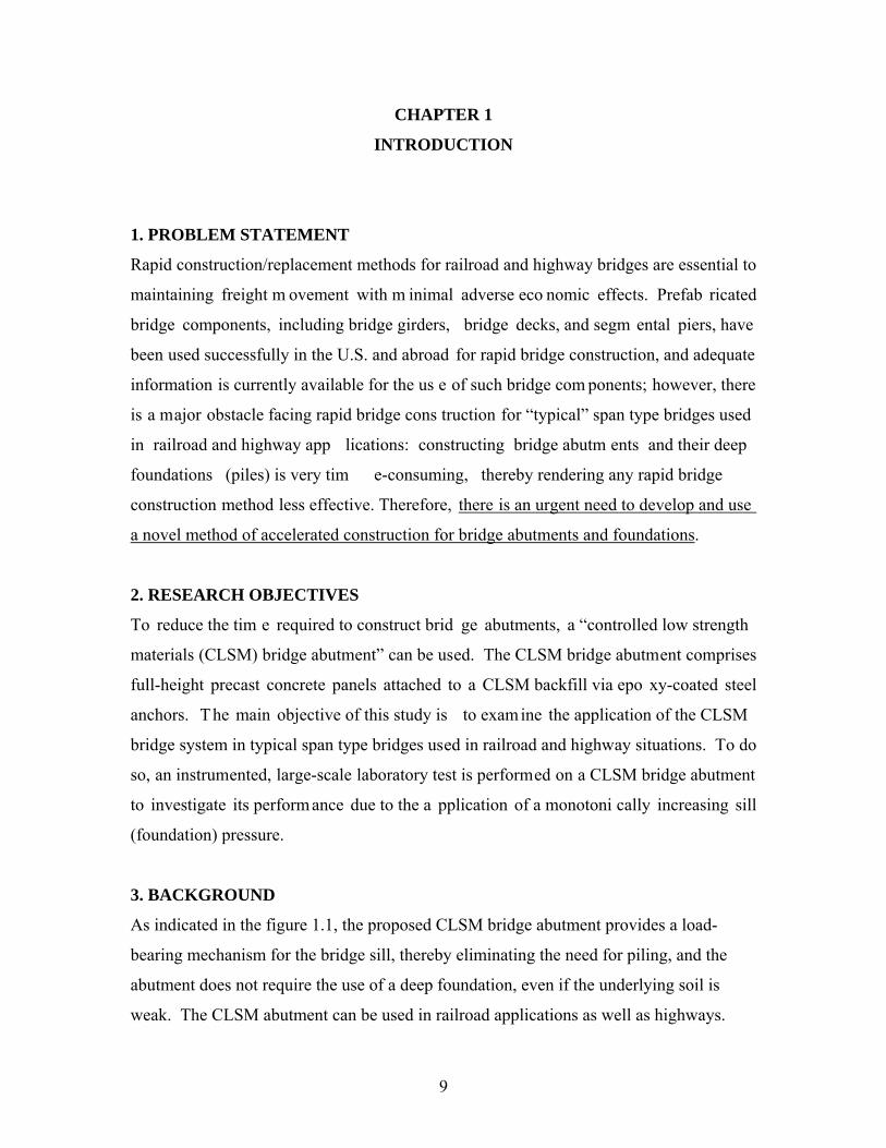
CHAPTER 1
INTRODUCTION
1. PROBLEM STATEMENT
Rapid construction/replacement methods for railroad and highway bridges are essential to
maintaining freight m ovement with m inimal adverse eco nomic effects. Prefab ricated
bridge components, including bridge girders, bridge decks, and segm ental piers, have
been used successfully in the U.S. and abroad for rapid bridge construction, and adequate
information is currently available for the us e of such bridge com ponents; however, there
is a major obstacle facing rapid bridge cons truction for “typical” span type bridges used
in railroad and highway app lications: constructing bridge abutm ents and their deep
foundations (piles) is very tim e-consuming, thereby rendering any rapid bridge
construction method less effective. Therefore, there is an urgent need to develop and use
a novel method of accelerated construction for bridge abutments and foundations.
2. RESEARCH OBJECTIVES
To reduce the tim e required to construct brid ge abutments, a “controlled low strength
materials (CLSM) bridge abutment” can be used. The CLSM bridge abutment comprises
full-height precast concrete panels attached to a CLSM backfill via epo xy-coated steel
anchors. The main objective of this study is to examine the application of the CLSM
bridge system in typical span type bridges used in railroad and highway situations. To do
so, an instrumented, large-scale laboratory test is performed on a CLSM bridge abutment
to investigate its perform ance due to the a pplication of a monotoni cally increasing sill
(foundation) pressure.
3. BACKGROUND
As indicated in the figure 1.1, the proposed CLSM bridge abutment provides a load-
bearing mechanism for the bridge sill, thereby eliminating the need for piling, and the
abutment does not require the use of a deep foundation, even if the underlying soil is
weak. The CLSM abutment can be used in railroad applications as well as highways.

10
Because of system flexibility and lack of piling, the long-term settlement of the sill is
likely to occur at the same rate of the settlement of the roadway bed thus reducing the
differential settlement and the associated “bumps” at the edges of the bridge.
CLSM bridge abutm ents can be co nstructed in a very sho rt time because they do not
require heavy machinery for excavation and co mpaction, and, most importantly, they do
not require the use of piles and pilin g equipment. It is antic ipated that with the CLSM
bridge system a complete bridge can be constructed in less than a week compared with a
typical construction time of several months for a conventional bridge of the same size. In
our large-scale laboratory test performed as part of this research, we applied very high
foundation loads on the seventh day after placing the CLSM fill; shorter waiting times are
also possible.
It is noteworthy that CLSM has been used by several state DOTs as self-leveling backfill
behind conventional pile-supported bridge abutme nts to alleviate the “bump” at the end
of the bridge (i.e., approach settlements). In the proposed CLSM abutment, however, the
CLSM abutment itself will prov ide the bea ring mechanism for the bridge s ill. This
unique approach has never been attem pted previously, but it has the potential to
profoundly reduce the cost and construction tim e of bridge abutm ents. The large-scale
laboratory test provided in-d epth understanding of the behavior of the proposed C LSM
abutment and showed that it can carry bridge loads with a large safety margin (FS>3) and
with minimal deformations (<0.2 inch).
3.1 What is CLSM?
CLSM (flowable fill) is def ined as self-compacting cementitious material that is in a
flowable state at the time of placement and has a specified compressive strength of 1200
psi or less at 28 days, but is defined as excavatable if the compressive strength is 300 psi
or less at 28 days (ACI 1999). CLSM contai ns water, cement, fly ash, adm ixtures, and
aggregates. ACI (1999) reports that the wet density of CLSM ranges between 85 and 145
pcf, but the dry density is substantially less than the wet density due to water loss.

11
CLSM is durable, excavatable, erosion-resistant, self-leveling; it cures rapidly and is
incompressible after curing, and flowable around confined spaces. It also can reduce
possible cave-ins, and it uses environmentally impacted materials such as fly ash within
its mix (Trejo et al., 2004; Hajafi and Tia 2004; and Newman et al., 1993). Hajafi and
Tia (2004) noted that when flowable fill is used the need for compaction is eliminated,
Figure 1.1: Comparison between Conventional and CLSM Bridge Abutments
12
thereby reducing equipment needs, labor costs, and the amount of inspection. CLSM also
can be placed all in one pour.
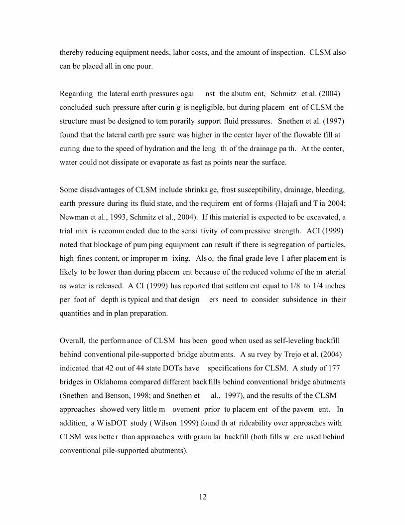
Regarding the lateral earth pressures agai nst the abutm ent, Schmitz et al. (2004)
concluded such pressure after curin g is negligible, but during placem ent of CLSM the
structure must be designed to tem porarily support fluid pressures. Snethen et al. (1997)
found that the lateral earth pre ssure was higher in the center layer of the flowable fill at
curing due to the speed of hydration and the leng th of the drainage pa th. At the center,
water could not dissipate or evaporate as fast as points near the surface.
Some disadvantages of CLSM include shrinka ge, frost susceptibility, drainage, bleeding,
earth pressure during its fluid state, and the requirem ent of forms (Hajafi and T ia 2004;
Newman et al., 1993, Schmitz et al., 2004). If this material is expected to be excavated, a
trial mix is recomm ended due to the sensi tivity of com pressive strength. ACI (1999)
noted that blockage of pum ping equipment can result if there is segregation of particles,
high fines content, or improper m ixing. Als o, the final grade leve l after placem ent is
likely to be lower than during placem ent because of the reduced volume of the m aterial
as water is released. A CI (1999) has reported that settlem ent equal to 1/8 to 1/4 inches
per foot of depth is typical and that design ers need to consider subsidence in their
quantities and in plan preparation.
Overall, the perform ance of CLSM has been good when used as self-leveling backfill
behind conventional pile-supported bridge abutments. A su rvey by Trejo et al. (2004)
indicated that 42 out of 44 state DOTs have specifications for CLSM. A study of 177
bridges in Oklahoma compared different backfills behind conventional bridge abutments
(Snethen and Benson, 1998; and Snethen et al., 1997), and the results of the CLSM
approaches showed very little m ovement prior to placem ent of the pavem ent. In
addition, a W isDOT study ( Wilson 1999) found th at rideability over approaches with
CLSM was bette r than approache s with granu lar backfill (both fills w ere used behind
conventional pile-supported abutments).

13
3.2 What is a CLSM Bridge Abutment?
Figure 1.1(b) shows a sc hematic diagram of a typical CLSM bridge abutment with full-
height precast concrete panel facing; in contrast, Figure 1.1(a) shows a schem atic
diagram of a conventional bridge abutm ent with pile foundation. As indicated in Figure
1.1(b), the CLSM bridge abutment provides a load-bearing mechanism for the bridge sill,
thereby eliminating the need for p iling, and the CLSM abutm ent itself does not require
the use of a deep foundation, even if the underlying soil is weak. If the foundation soil is
found unacceptable, a flowable fill foundation may be used to provide a stronger platform
for the cons truction. T he flowable fill f oundation may involve rem oving about a 3-ft
thick layer of the foundation soil and simply replacing it with a flowable fill. The sill can
be precast or cast-in-place reinforced concrete.
The interlocking full-height concrete panels provide a form that contains the newly
poured CLSM backfill u ntil setting. The theory behind CLSM bridge ab utments is that
the epoxy-coated steel anchors make the CLSM mass and the full-height concrete panels
behave as a single unit. The concrete facing panels and the reinforced CLSM m ass are
then treated as one unit and analyzed as a large gravity wall, which must be analyzed for
stability in sliding and overt urning. In addition, the nu mber of epoxy-coated steel
anchors required and their spacing must be de termined. Finally, the bearing pressure of
such a large gravity wall m ust be checked to ensure that it does not exceed the allowable
bearing capacity of the soil. The in ternal stability of the CLSM wall m ust be ensured, as
well. Rupture occu rs when excessive forces exceed the ultim ate tensile strength of the
epoxy-coated steel anchors. Slippage of reinforcement in the CLSM-reinforcem ent
composite can occur when the interface friction (bond) is insufficient.
The proposed CLSM bridge abu tments have great pro mise in term s of ductility,
flexibility, constructability, and costs. One major advantage of CLSM abutm ents is that
they can be constructed rapidly without the need for compaction, piling, and heavy
machinery.

14
4. CONSTRUCTION PROCEDURE FOR CLSM ABUTMENTS
The construction sequence of a CLSM bridge abutment is very si mple and involves the
following steps (see Figure 1.2):
1. Level the foundation soil and place a precas t concrete leveling pad for the precast
concrete panels.
2. Install interlocking full-height concrete panels (Example: 18-ft high panels) with
temporary lateral supports.
3. Place a 6-ft thick layer of CLSM (flowable fill).
4. Install the first row of epoxy-coated ¾-inch diameter steel anchors (insert through the
opening from outside). This can be done even before the flowable fill is set since the
guide hole in the concrete panel will keep the anchor in a horizontal position.
5. Place the second 6-ft thick layer of flowable fill.
6. Install the second row of epoxy-coated ¾-inch diameter steel anchors.
7. Place the last 6-ft thick layer of flowable fill.
8. Wait for the flowable fill to set (usually 24-48 hours) then remove lateral supports.
9. Place the precast concrete bridge sill, place the approach fill behind the sill, and place
the precast concrete bridge on elastomeric pads (or the equivalent) affixed to the sill.
The bridge does not need to have an approach slab, as road base material can b e
compacted directly b ehind the b ridge sill to form the approach way and to create a
gradual transition from the roadway to the bridg e. Asphalt pavement can then be placed
on the bridge and approach without a convent ional joint system (approach slab) at the
bridge ends. The in tent is to allow the bridge and the adja cent road to settle toge ther,
providing a smooth, bump-free ride for drivers traveling on and off the bridge.
The CLSM bridge system does not use piles an d is more suited for single-span bridges in
critical crossings. Single-span br idges are m ore tolerant of settlement than m ulti-span
structures, and the CLSM bridge system is designed to compensate for post-construction
settlement; the bridge, abutm ent, and a pproach are supported on the sam e foundation
system. The bridge is designed for uniform settlement
between the sub- and superstructures.

15
5. RECOMMENDATIONS FOR FUTURE RESEARCH
The research team suggests a full-scale field construction of a CLSM bridge syste m
(Figure 1.3) to dem onstrate its feasibility as a rapid bridge cons truction method. In
addition to showing the short- and long-term performance of the CLSM bridge system,
the field work will als o enable br idge engineers and geo technical engineers to gain
experience and become familiar with the proposed rapid construction method. The work
will also im proved current understanding of th e behavior of CLSM bridge abu tments
carrying realistic bridge loads.
Figure 1.2: Construction Sequence

16
The CLSM bridge abutm ents, the concrete sl ab (deck), an d the br idge girders can be
instrumented, as shown in Figure 1.3, with st rain gauges, pressure cells, displacem ent
gauges, and surveying points to measure th eir behavior during construction and upon
application of construction and service loads. Measurements should continue for several
years after com pletion of the construction to investigate the long-term behavior of the
prefabricated bridge elem ents and the CLSM a butments. Of particular interest is the
vertical displacement of the bridg e and the la teral displacement of the full-height facing
panels. An extensive array of displacem ent gauges and surveying targets can be used to
measure horizontal and vertical d isplacements of the bridge , the appro ach fill, and the
abutment facing. The displacem ent gauges can be mounted on a reference steel fram e
supported by two piles driven near the bridge abutm ent (not shown in the figure). A
pavement profiler can be used to quantify a pproach settlements. Also, because of the
three-dimensional nature of the proposed construction, the wing walls should be
instrumented with surveying targets to measure their lateral displacements. Based on the
results of the field testing and monitoring, an updated design guide can be developed.
Figure 1.3: Proposed Field Test with CLSM Bridge Abutments
17
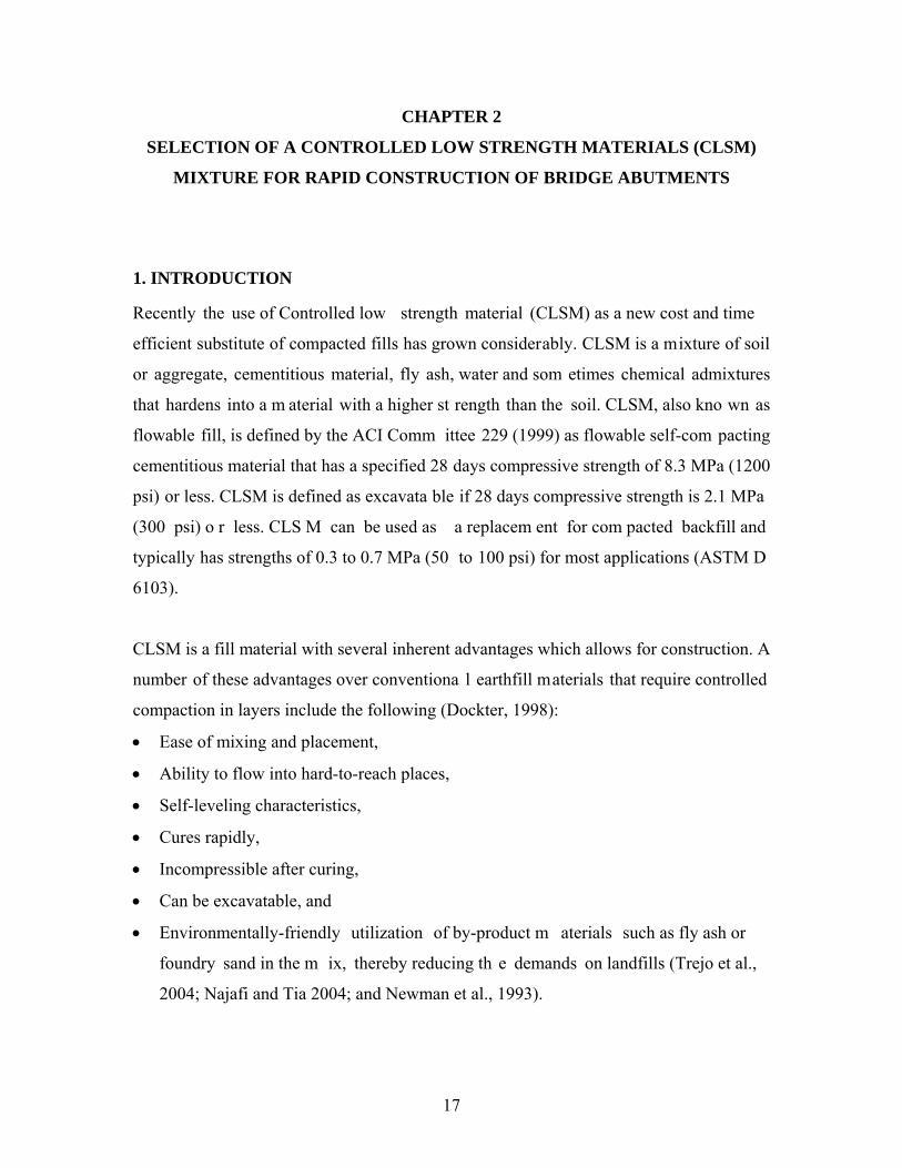
CHAPTER 2
SELECTION OF A CONTROLLED LOW STRENGTH MATERIALS (CLSM)
MIXTURE FOR RAPID CONSTRUCTION OF BRIDGE ABUTMENTS
1. INTRODUCTION
Recently the use of Controlled low strength material (CLSM) as a new cost and time
efficient substitute of compacted fills has grown considerably. CLSM is a mixture of soil
or aggregate, cementitious material, fly ash, water and som etimes chemical admixtures
that hardens into a m aterial with a higher st rength than the soil. CLSM, also kno wn as
flowable fill, is defined by the ACI Comm ittee 229 (1999) as flowable self-com pacting
cementitious material that has a specified 28 days compressive strength of 8.3 MPa (1200
psi) or less. CLSM is defined as excavata ble if 28 days compressive strength is 2.1 MPa
(300 psi) o r less. CLS M can be used as a replacem ent for com pacted backfill and
typically has strengths of 0.3 to 0.7 MPa (50 to 100 psi) for most applications (ASTM D
6103).
CLSM is a fill material with several inherent advantages which allows for construction. A
number of these advantages over conventiona l earthfill materials that require controlled
compaction in layers include the following (Dockter, 1998):
Ease of mixing and placement,
Ability to flow into hard-to-reach places,
Self-leveling characteristics,
Cures rapidly,
Incompressible after curing,
Can be excavatable, and
Environmentally-friendly utilization of by-product m aterials such as fly ash or
foundry sand in the m ix, thereby reducing th e demands on landfills (Trejo et al.,
2004; Najafi and Tia 2004; and Newman et al., 1993).

18
Najafi and Tia (2004) noted that when flowable fill is us ed the need for compaction is
eliminated. This reduces equipment needs, labor costs and the associated inspections.
Although CLSM m ixtures provide numerous advantages, there are som e technical
challenges. The major challenge in application of CLSM is that this material behaves like
a compacted soil. Therefore, m uch of the available knowledge and publications on its
applications had f allen between the concr ete materials engineering and geotechnical
engineering and it is often not given the leve l of attention it deserve s by either g roup
(Javed et al., 2002).
Some disadvantages of CLSM hindering extens ive use of this material, include (Najafi
and Tia 2004; Newman et al., 1993, Schmitz et al., 2004):
Susceptibility to segregation and bleeding,
High lateral pressures during placement,
High shrinkage,
Potential leaching of constituent materials, and
Reduced durability of CLSM subjected to freezing and thawing cycles.
Investigation using trial mix is often recommended especially if CLSM is expected to be
excavated in the future. Excessive long-term strength gain makes it difficult to excavate
CLSM at later stages. ACI Co mmittee 229 (1999) noted that segregation of particles,
high fines content, or improper m ixing may result in blockage of pumping equipm ent.
Halmen et al. (2005) believes that the m ajor challenge in implementation of the use of
CLSM is the lack of knowledge on the corros ion performance of steel pipe m aterials
embedded in CLSM.
CLSM is a multipurpose construction m aterial that has been used in a wide variety of
applications that are well documented in the literature. The primary application of CLSM
is as a ba ckfill in place of compacted soil. Among the many applications of CLSM, the
following are the most important (ACI Committee 229, 1999 and NRMCA, 1989):
Backfill for sewer trenches, conduit trenches , utility trenches, building excavations,
bridge abutments and retaining walls;

19
Structural fill for foundation footings, sub f ootings, floor slab bases, road bases,
subbases, subgrades, and utility bedding;
Void-filling for underground storage tanks, abandoned sewers, abandoned utility,
voids under pavement, basements or other underground structures;
Bridge approaches; either as a subbase for the bridge approach slab or as backfill with
other elements.
Utility bedding applications involve the us e of CLSM as a bedding m aterial for p ipes,
electrical and other types of utilities, and conduits. Because it resis ts erosion better than
many other f ill materials, CLSM can be used for erosion c ontrol in e mbankments and
slopes, and to fill voids under culverts, pav ements, sidewalks, bridges and other
structures where natu ral soil or noncohesi ve granular fill has eroded away (ACI
Committee 229, 1999). It was also indicated th at appropriate CLSM m ixtures can be
designed as anti co rrosion fill, thermal and isolation f ill (Brewer, 19 94). The us e of
CLSM for encapsulation of contaminated soil was also docum ented in the lite rature
(Melton, 2005). CLSM is used in nuclear facilities for conventional applications because
it decreases personnel exposure to radiation (ACI Committee 229, 1999).
2. EXPERIMENTAL PROGRAM
Material specification tests were conducted to design the appropriate CLSM mix for rapid
construction of bridge abutments (CLSM Abutments), and to obtain required engineering
properties of the m ixtures for future num erical analysis. The e ngineering properties
investigated include flo wability, density, unconfined com pressive strength and stress–
strain behavior. The CLSM bridge abutm ent comprises full-height precast concrete
panels that are attached to a CLSM backfill via steel anchors, Figure 2.1. Therefore, the
bond capacity of steel anchors embedded in the CLSM was also investigated.

20
Figure 2.1: Embedded Anchors in CLSM Backfilled Abutment
2.1 Materials
The selected materials include Type I Portla nd cement, Class F fly ash, fine aggregates
and water. Selection of materials for CLSM should be based on availability, cost, specific
application and the n ecessary characteristics of the m ixture including flowability,
strength, excavatablity, density, etc (ACI Committee 229, 1999).
The Type I Portland cem ent used in this research meets all applicable chem ical and
physical requirements of ASTM C 150, “Sta ndard Specification for Portland Cem ent”
and is manufactured by Lafarge Cement Co. Fly ash is one of the by-products generated
from the coal com bustion in electric power generating plants. Fl y ash used in this
research was Class F ty pe from We Energies, the Elm Road Generating Station (ERGS),
Concrete Panels

21
located along the shore of Lake Michig an near the ex isting Oak Creek Power Plant
(OCPP), Wisconsin.
Concrete sand was used as fine aggregates. This sand was in the labo ratory at a r oom
temperature; the m oisture content was 1.16%. Potable tap water at approxim ate room
temperature of 23 ºC (75 ºF) was used as m ixing water for production of the flowable fill
mixtures.
2.2 Mixture Proportioning
CLSM mixtures are usually designed base d on developm ent of com pressive strength.
Digioia and Brenda (1992) noted that the appropriate control of strength in flowable fill is
a main criterion in a m ix design. To design CLSM mix, it is not just required to m eet
minimal strengths to m aintain and provide suitable structural support, but also the
ultimate strength must be controlle d to a llow for future excavation (Lovencin et al.,
2006).
Due to the sensitivity of compressive strength and other properties, trial and error process
has been recommended for proportioning of flowable fill mixtures (FHWA, 1997). When
a CLSM m ixture is designed, a number of e ngineering parameters must be evaluated
prior to, du ring, and after p lacement in the field (Javed et al., 2002 ). Depending on
specific application of flowable fill in this project, the f ollowing criteria were se t for
CLSM mixture:
Strength development;
Time of set;
Flowability; and
Bond behavior between the rebar and CLSM
Initial mixtures were tested for flowability and compressive strength to identify the key
components and com positions of CLSM wh ich can reach the target strength and
flowability. Trial m ixtures were evaluated and then ad justed to achieve the target
properties (ACI Committee 229, 1999).

22
Initially, excavatable and nonexcavatable m ixtures were examined. The selection criteria
favored the m ix with high early s trength and with 28 day s strength not exceeding 8.3
MPa (1200 psi). Besides, it was desired to obtain the m ixture proportions with lower
ultimate strength to allow for future excavatable construction option. Finally, 20 different
CLSM mixtures with different levels of cement content, fly ash dosage and water to
cement (w/c) ratios were produced.
In this study, 100 × 200 mm (4 8 in.) cylindrical molds were used to cast the specimens
for the determ ination of com pressive strength (ASTM D 4832). The specim ens were
cured for varying periods, 1 day, 7 days and 28 days, before the com pressive strength
tests. For each curing period, three cylindrical samples, so totally nine specim ens were
produced and tested p er each m ix. Therefore, for the whole research study, 180
cylindrical CLSM specimens were cast.
2.3 Preparation of CLSM Mixtures
The test cylinder m olds were always prope rly cleaned and grease d with m ineral oil
before preparation of CLSM mixtures. All constituent materials, cement, fly ash and sand
were carefully weighed and placed into buckets with sealed lids.
The batching sequence was to p lace the sa nd into the m ixer and it was m ixed for ½
minute to make the sand uniform, and then most of the mixing water was added followed
by the addition of cement and fly ash. After placement of the materials into the mixer, the
mixer was kept rotating for three m inutes, then the remaining mixing water was added.
The mixing was resumed for 2½ additional minutes.
Immediately after mixing, flowable fill was poured into a large container ready to cast the
prepared specimen molds. Prior to pouring into specim en molds, a sample of the fresh
mix was tested to m easure plastic properties including unit weight (ASTM D 6023) and
flowability (ASTM D 6103). Each specim en was properly m arked and lab eled for
identification and testing purposes.

23
Because of the self-leveling characteris tic of CLSM, castin g the cylinder molds did not
require densification as is norm ally needed for concrete samples. After specimens were
cast, they were cured at room temperature. Specimens were kept in th e molds until the
testing age.
2.4 Test Methods
2.4.1 Flowability Tests
Flowability tests had to be conducted in order to assure the CLSM ability to fill the whole
abutment in one lift and to prevent blocka ge of pum ping equipment. Flowability of
mixtures was measured according to the “Standard Test Method for Flow Consistency of
CLSM” (ASTM D 6103) and the desired flowability was 350 mm (14 in.), see Figure 2.2.
Figure 2.2: Standard Test Method for Flow Consistency of CLSM
2.4.2 Compressive Strength
Cylindrical specimens were tested to determine the compressive strength of the m aterial
(Figures 2.3 and 2.4). Rem oving the specimen from the mold involved careful handling

24
due to its low strength (as com pared to hardened concrete cylinders). The cylinders were
then tested to obtain the compressive strengths (ASTM D 4832). Three 100 × 200 mm (4
8 in.) cylindrical specim ens from each batch were tes ted at 1, 7 and 28 days exc ept
when obstructed by cylinder dam age from demolding. The com pression tests were
performed using a rela tively low-load capacity computerized testing machine with load
control loading. Table 2.1 shows different CL SM mixture proportions tested in this
research study, flowability and compressive strength results for 1, 3 and 28 days age.
Table 2.1: Mixture proportions and performance of investigated CLSM
Compressive Strength, MPa (psi)
Mix
#
Cem
ent,
kg/m
3 ,
(lb/y
d3 )
Fly
ash,
kg/
m3 ,
(lb/y
d3 )
Sand
, kg/
m3 ,
(lb/y
d3 )
Wat
er, k
g/m
3 ,
(lb/y
d3 )
Plas
ticiz
er (m
l)
Flow
, mm
(in.
)
Den
sity
kg/
m3 ,
(lb/ft
3 )
w/c
m
1 da
y
7 da
ys
28 d
ays
1 82 20 14 98 210 - 159 1810 2.05 - 0.20.03 0.510.05
(138) (35) (2525) (354) (6.25) (113) (294.4) (747.5)
2 79 20 14 58 452 - 241 2009 4.60 - 0.160.04 0.390.02
(133) (33) (2458) (762) (9.5) (125.4) (23.25.9) (562.9)
3 123 31 1215 706 - 140 2074 4.58 - 0.240.02 0.590.05
(208) (52) (2047) (1189) (5.5) (129.5) (353.6) (867.4)
4 92 23 13 55 527 - 178 1996 4.60 - 0.210.03 0.560.04
(154) (39) (2284) (888) (7) (124.6) (30.34.3) (816.1)
5 50 270 1569 245 - 210 2134 0.76 0.160.06 0.210.05 -
(85) (455) (2644) (413) (8.25) (133.2) (22.78.7) (317.5)
5R 50 269 1562 259 - 210 2140 0.81 0.200.02 0.270.02 1.890.29
(84) (453) (2633) (437) (8.25) (133.6) (29.42.5) (39.42.4) (27442)
6 50 260 1514 303 - 432 2127 0.99 0.100.01 0.560.07 1.480.11
(84) (439) (2552) (510) (17) (132.8) (15.11.4) (8110.2) (21416)
7 274 51 1594 229 135 210 2148 0.71 0.410.05 4.280.19 9.760.32
(462) (86) (2686) (387) (8.25) (134.1) (59.36.6) (62127.1) (141647)
8 268 50 1556 268 50 203 2142 0.84 1.870.04 13.290.29 -
(451) (84) (2623) (451) (8) (133.7) (2716.3) (192742)
9 279 465 1115 297 12.5 241 2156 0.40 1.280.07 16.264.18 -
(470) (783) (1880) (501) (9.5) (134.6) (1869.8) (2358606)

25
10 172 576 1122 299 12.5 222 2169 0.40 0.290.02 6.460.22 9.110.88
(290) (971) (1891) (504) (8.75) (135.4) (42.32.7) (93731.3) (1322127)
11 47 268 1579 221 12.5 191 2116 0.70 0.140.03 1.000.12 2.090.10
(80) (452) (2662) (373) (7.5) (132.1) (20.24.9) (14517.8) (30315)
12 56 319 1501 263 19 267 2139 0.70 0.130.00 1.020.04 2.140.13
(95) (538) (2529) (443) (10.5) (133.5) (18.30.5) (1486.2) (31119)
13 75 300 1499 267 19 267 2142 0.71 0.120.01 1.490.03 2.850.08
(126) (505) (2527) (451) (10.5) (133.7) (17.92) (2164.8) (41412)
14 45 258 1516 303 - 356 2122 1.00 0.080.00 0.380.01 0.850.09
(77) (434) (2555) (511) (14) (132.5) (110.6) (551.8) (12413)
15 76 497 1338 287 21 330 2198 0.50 0.190.01 1.970.02 4.390.69
(129) (838) (2255) (483) (13) (137.2) (27.61.2) (2852.9) (636100)
16 95 572 1240 267 25 305 2175 0.40 0.420.00 3.680.21 8.200.18
(161) (965) (2091) (450) (12) (135.8) (60.50.7) (53430.5) (119026)
17 87 299 1545 251 12.5 229 2182 0.65 0.440.01 1.920.04 3.900.32
(146) (504) (2603) (423) (9) (136.2) (63.42.1) (2796.1) (56547)
18 57 323 1521 266 12.5 330 2167 0.70 0.160.01 0.940.06 1.880.02
(96) (545) (2564) (449) (13) (135.3) (23.51.3) (1368) (2723.1)
19 58 331 1557 234 12.5 191 2180 0.60 0.300.00 1.410.07 2.870.27
(98) (558) (2625) (394) (7.5) (136.1) (43.30.7) (20510.7) (41739)
Note: R in mixture number = mixtures that were replicated.
w/cm = water/cementitious materials
Strength is the main parameter to design a c oncrete and flowable fill m ixture. Figure 2.5
shows that the ratio of water to cementitious material (cement and fly ash) is an important
factor affecting the strength of flowable fill (like concrete). The plot illustrates that as the
water to c ementitious ratio (w/cm) increases, strength of CLSM decreases. The other
important factor in determ ining bearing strength is cement content. Figure 2.6 indicates
that CLSM m ixtures with the sam e levels of w/cm , gain hi gher strength when ce ment
content is increased. Also strength of CLSM improves by adding fly ash to a mix (Figure
2.7). In addition to s trength, it was noted th rough visual observation that the mixes
containing higher fly ash content have less bleeding and segregation.

26
Figure 2.3: Unconfined Compression Test Apparatus

27
Figure 2.4: Crushed CLSM Specimen

28
Figure 2.5: Relationship between 28-day compressive strength and w/cm ratio
Figure 2.6: Relationship between 28-day compressive strength and cement content at
given w/cm

29
Figure 2.7: Relationship between 28-day compressive strength and fly ash content
Initially six mixtures were sele cted based on strength and f lowability. Compressive
strength of these m ixtures was ranged from a low strength of 0.85 MPa (124 psi) to a
high strength of 8.2 MPa (1190 psi). F igure 2.8 dem onstrates the developm ent of
compressive strength with the curing age of the selected mixtures.
In addition to com pressive strength, the st ress-strain response of all cylinders was
obtained. A typical behavior of all tested mixtures was a changing stress-strain response
with the curing tim e. Early-age CLSM cylinders showed more ducti le response like soil
samples, but with age, CLSM behaved more like concrete with higher strength and lower
ductility. This behavior is illustrated in Figure 2.9 for mixture #14. This change in stress-
strain behavior is also not ed by F olliard et al (1999). St ress-strain curve would also
provide the elastic modules of the mixtures which is useful in the finite element analysis.

30
Figure 2.8: Compressive strength development for selected CLSM mixtures
Figure 2.9: Stress-strain responses for mix #14 at 1, 7 and 28 days

31
2.4.3 Bond behavior between steel rebar and CLSM
Due to the special design of the CLSM bridge abutment, steel rebar anchors are in contact
with CLSM, as illus trated by Figure 2.1. Pull-ou t tests of the steel anchors were
conducted to ensure the internal stabilit y of the CLSM abutm ent. Slippage of
reinforcement in the CLSM-steel composite can occur when the interface friction (bond)
is insufficient. The res ults of these tests would also be used to obtain the in terface
parameters needed for the finite element analysis.
Due to the importance of the bonding strength, three different pull-out test set-ups were
implemented to achieve reliable results.
2.4.3.1 Pull-out test type 1
From the six selected m ixtures, two mixtures, #14 and #16, were tested. Mix #16 has a
high compressive strength equal to 8.2 MPa (1190 psi) to m ake a strong backfill and
could be used if excavation is not intende d. Mix # 14 has the aver age strength of 0.85
MPa (124 psi) which is within the range of excavatable CLSM.
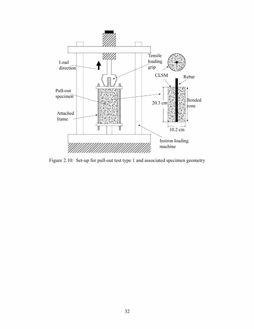
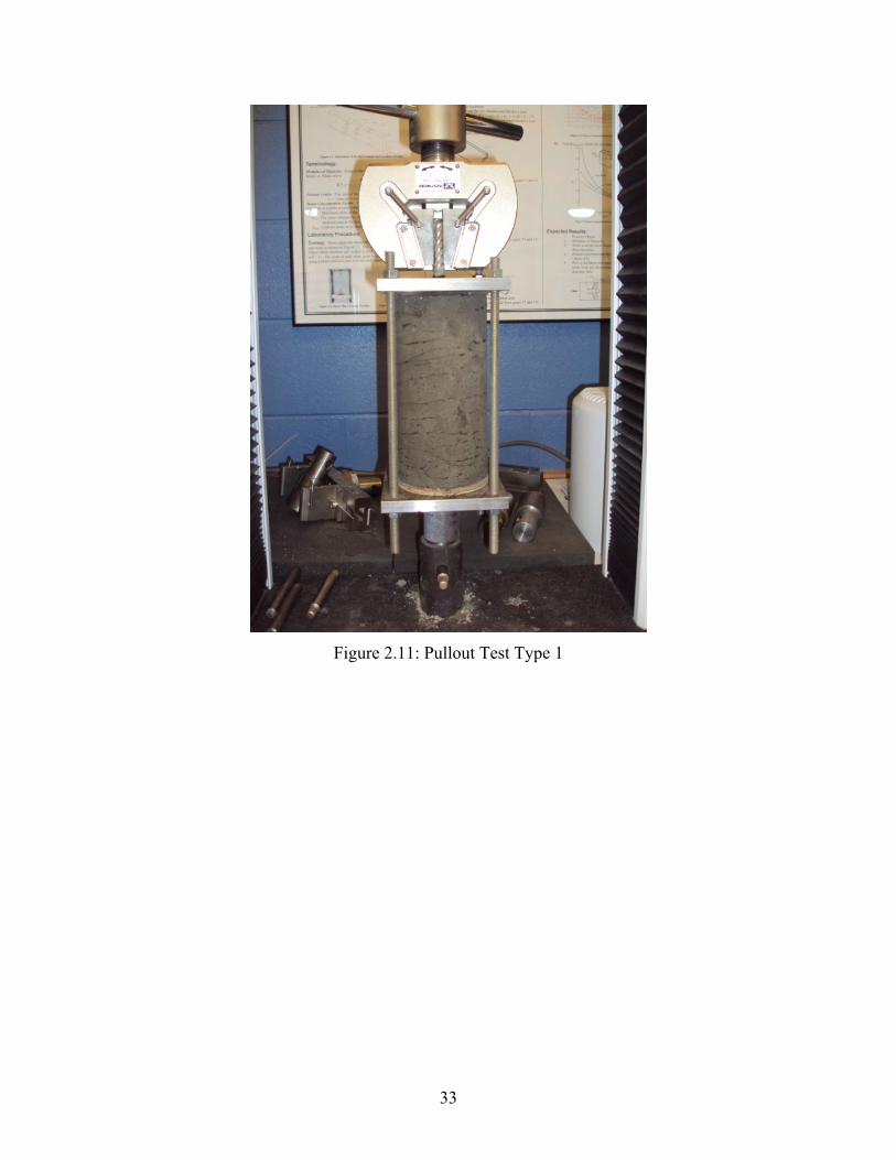
In order to measure the pullout resistance of a steel bar embedded in the CLSM mixtures
a special set-up was m ade and attached to the Instron m achine, see Figures 2.10-2.12.
Cylindrical CLSM samples, 100 × 200 mm (4 8 in.), with ribbed steel bar, 12.7 mm
diameter and 27.9 cm length, placed in the center, were cast and cured for 1, 7 and 28
days. For each curing period 3 pull-out tests were performed for each. Pull-out load
versus slip of the rebar f or both mixtures is illustrated in Figure 2.13. Table 2.2 provides
the average pull-ou t resistance results at each cu ring period for both mixtures. In this
test, the failure of the sample was clearly affected by the boundaries (Figure 2.12), which
indicates that prior to the slip failure of the rebar, the cylinder in fact had failed. This
inaccuracy presented th e need for another pull-out test set-up which can im plement
CLSM specimens with larger cross sectional area.
32
Figure 2.10: Set-up for pull-out test type 1 and associated specimen geometry
33
Figure 2.11: Pullout Test Type 1

34
Figure 2.12: Effect of Pullout on CLSM Specimen
Figure 2.13: Pull-out load vs. slip for mix #14 and #16 (pull-out test 1)
Mix #14 Mix #16

35
Table 2. Results of pull-out test 1
Mix
#
Pullout resistance,
1- day, kN, (lb)
Pullout resistance,
7-days, kN, (lb)
Pullout resistance,
28-days, kN, (lb)
14 0.45 (101) 1.35 (304) 2.7 (606)
16 1.57 (352) 6.48 (1457) 14.18 (3187)
2.4.3.2 Pull-out test type 2
The excavatable m ixture, mix #14, was further investigated for large-scale testing. A
wooden box of 0.61 m × 0.61 m × 0.91 m (2 ft × 2 ft × 3 ft ) was made and divided into
four equal partitions. Four ribbed rebars, 12.7 mm (0.5 in.) diam eter and 1.1 m (3.5 ft )
length, were placed and secured in the center of each partition, Figure 2.14 and 2.15. The
box was filled with CLSM while s ome cylindrical molds were filled and placed in the
center of the box for com pression test. It was intended to compare the strength of the
material inside the mass backfill with the known compressive strength of the mixture.
A frame was made over the box to set up th e loading device and in strumentations, see
Figure 2.16. A hydraulic jack wa s used for the loading. Afte r 7 days curing, the tension
load was applied gradually to each rebar and the slip wa s measured. Figure 2.15 shows
the condition of the CLSM after a pullout test. Figure 2.17 illustrates the typical result of
the tests. The average pull-out load for slip failure of the rebars was 21.3 kN (4800 lb)
(with the coefficient of vari ation of 6.28%). After the pu ll-out tests, the cylinders
embedded inside the box were retrieved to measure their com pressive strength. The
average compressive strength of the samples at 7 days was about 75 psi which is more
than the strength found through standard sam pling for compression test. This m ight be
due to the temperature, drainage and coverage condition inside of the fill.

36
Figure 2.14: Pullout Test Type 2

37
Figure 2.15: CLSM Specimen After Pullout
Figure 2.16: Set-up for Pull-out test type 2

38
Figure 2.17: Pull-out load vs. slip (pull-out test type 2)
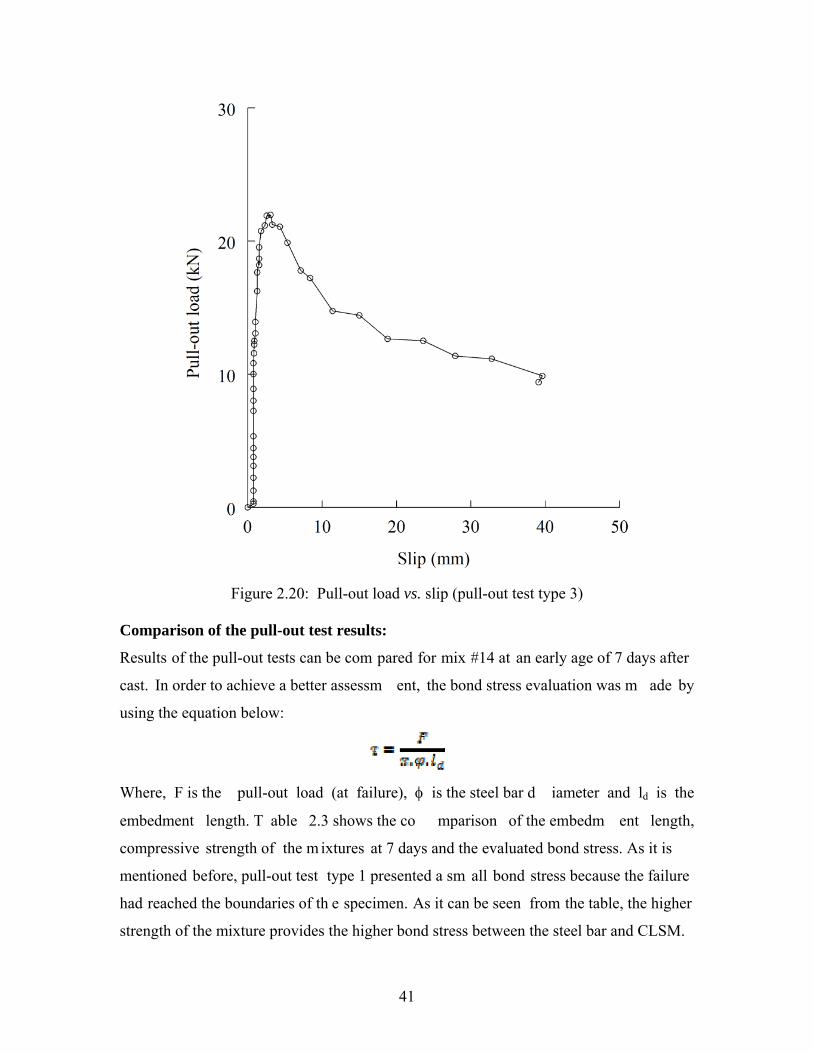
2.4.3.3 Pull-out test type 3
In order to verify the results of the last pull-out test se t-up, it was decided to perform a
real scale pull-out test with the same length of em bedment as the steel ancho rs in the
large-scale CLSM bridge abut ment test. Two extra steel anchors, 12.7 mm (0.5 in.)
diameter and 1.25 m (49 in.) length, were pl aced inside the abutm ent at wing w alls
through drilled holes in the concrete pane ls. These anchors were long enough to extend
beyond the concrete face to allow the attach ment of required testing equipm ent for the
pull-out test.
Seven days after CLSM placement (mix #14) behind the testing abutment and prior to the
main test, a hydraulic jack loading device, a load cell and a Linear Variable Differential
Transformer (LVDT) were attached to the anchors (Figure 2.18 and 2.19) and the tension

39
load was monotonically increased until the pull-out rupture occurred. The measured pull-
out load versus slip of the steel anchor is shown in Figure 2.20. The average load for pull-
out rupture of the rebars was about 21.8 kN (4900 lbs).
It was anticipated to get m ore pull-out load for this real-scale test because the length of
embedment of steel bars was larger. The reason is that ev en though a ready mix concrete
was asked to make mix #14, the collected samples during the placement, revealed that the
batched mix had less 7-days compressive strength.
Figure 2.18: Set-up for pull-out test type 3

40
Figure 2.19: Pullout Test Type 3
41
Figure 2.20: Pull-out load vs. slip (pull-out test type 3)
Comparison of the pull-out test results:
Results of the pull-out tests can be com pared for mix #14 at an early age of 7 days after
cast. In order to achieve a better assessm ent, the bond stress evaluation was m ade by
using the equation below:
Where, F is the pull-out load (at failure), is the steel bar d iameter and ld is the
embedment length. T able 2.3 shows the co mparison of the embedm ent length,
compressive strength of the m ixtures at 7 days and the evaluated bond stress. As it is
mentioned before, pull-out test type 1 presented a sm all bond stress because the failure
had reached the boundaries of th e specimen. As it can be seen from the table, the higher
strength of the mixture provides the higher bond stress between the steel bar and CLSM.

42
Table 2.3: Comparison of the bond stress in pull-out tests for mix #14.
Pull-out
Test type
ld, m,
(in.)
fc, MPa, (psi)
, MPa,
(psi)
1 0.2, (8) 61, (0.42) 24.2, (0.17)
2 0.91, (36) 61, (0.42) 84.9, (0.58)
3 1.24, (49) 26, (0.18) 63.7, (0.44)
Note: fc = Compressive strength at 7 days

43
CHAPTER 3
A LARGE-SCALE LABORATORY TEST FOR RAPID CONSTRUCTION OF
CLSM BRIDGE ABUTMENTS
1. INTRODUCTION
Aging bridges with growing traffic dem ands has presented an increasing need for rapid
construction/replacement of bridg es to accomm odate traffic flow a nd maintain freight
movement with least adverse econom ic impact. Acco rding to the National Bridge
Inspection Standards (NBIS), m ost bridges in the U.S. are inspected at least once every
two years following the federal guidelines . In the December 2010 bridge inspection
report by the U.S. Depa rtment of Transportation, it is stated that a qua rter of the bridges
in the U.S. are classified as deficient. Or, of the 604,474 bridges in the United States,
146,633 are classified as deficien t, including 69,223 id entified as structurally deficient
and 77,410 as functionally obsolete bridges. Although all deficient bridges are not unsafe
for travel, the num bers reveal the p otential for many bridge replacement projects in the
forthcoming years. The traveling public demands that these construction and replacement
projects be com pleted more quickly to reduce congestion and to i mprove safety
(Okumus, 2008).
Conventional cast in place construction of the foundation, substructure, superstructure
components and other elem ents of bridges, demands a substantial amount of time as it
requires the sequential labor-intensive proce sses of forming, placing and curing tim e to
complete the pro ject. This m ay cause di sruption to the freight m ovement, and
inconvenience to the traveling public during the construction period.
To mitigate the traffic congestion problem s, it has been s hown that the use of precas t
concrete components in bridge s, including bridge girders, bridge decks, and segmental
piers, could be a good solution. Since these components can be fabr icated off-site, the
number of labor and tim e consuming construction tasks that must be fulfilled on-site is
reduced significantly. In addition to accelerat ed construction, the use of prefabricated
bridge systems can allow for better in-plant quality control, improved durability, reduced

44
life-cycle costs, use of innovative m aterials, better work-zone safety and m inimum
impact to the environment (Cheng and Capers, 2009).
The concept of using prefabricated elements in modern bridge construction has long been
researched and has produced ample volume of information. Normally, most of the bridge
construction duration is contro lled by the construction of the substructure that consists
typically of reinforced concrete abutm ents and piers with pile foundations. As such,
utilizing rapid construction of only the bridge superstructure can only result in minor time
saving. Hence, there is a vital need fo r developing and utilizing a novel m ethod of
accelerated construction for bridge substructures including bridge abutments.
2. CONTROLLED LOW STRENGTH MATERIAL (CLSM) BRIDGE
ABUTMENT
Effective rapid bridge construction m ay be achieved by using the “controlled low
strength materials (CLSM) bridge abutm ent”. The CLSM bridge abutm ent construction
is defined as using full-height precast concrete panels that are attached to a CLSM
backfill via steel anchors. The CLSM bridge abutm ent provides a load -bearing support
for the bridge sill, thus e liminating the need for piling systems. CLSM bridge abutments
can be con structed in a shorter time becaus e they do not require heav y machinery for
excavation, compaction, and piling equipment. Depending on the project s ize, it is
anticipated that several week s or even m onths may be sa ved with the construction of
CLSM integrated bridge system as com pared with the construction of a conventional
bridge abutment.
Figures 3.1(a) and 3.1(b) show schem atic diagrams of a conventional bridge abutm ent
with pile f oundation and a typical CLSM br idge abutment with full-height precast
concrete panel facing elem ents, respectively. As shown in Figure 3.1(b), the C LSM
bridge abutment provides a load-bearing support for the bridge sill, thu s eliminating the
need for pile foundations. It should be not ed that the CLSM abut ment does not require
the use of a deep foundation, ev en if the underlying soil is relatively weak. If the
underlying soil is weak , a flowable fill foundation m ay be used to provide a stro nger

45
platform for the construction. The flowable fill foundation may involve removing about
a 1-m (3-ft) thick layer of the foundation soil and simply replacing it with a flowable fill.
Figure 3.1: Comparison Between (a) Conventional Bridge Abutment and (b)
CLSM Bridge Abutment
The interlocking full-height precast concrete panels serve as for mwork that hold the
newly poured CLSM backfill in place un til the setting of the b ackfill materials is
complete. The concept behind the f avorable behavior of CLSM bridge abutment is based
on having the CLSM mass, the steel anchors, and the full-height concrete panels act as a
monolith. Accordingly, the concrete facing panels and the reinforced CLSM m ass are
then treated as one unit and analy zed as a large gravity wall. The required analysis
includes the effects of strength, and stabil ity in sliding and overturning. There are

46
external and internal stability requirements for the CLSM bridge abutm ent. External
stability of the CLSM abutment with bridge loading must be statisfied in terms of sliding,
overturning, and bearing capacity of the underlying soil. Internal s tability under bridge
loading must be satisf ied as well. I nternal stability is based on the tie-back concept in
which the s teel anchors are theo retically holding in place the concrete panels and the
CLSM wedge (behind the concrete panels) that is on the verge of ac tive failure (i.e., the
wedge is sliding towards the panels). Due to internal stability requirements, the anchors
are designed to (1) resist yielding with a pre-specified safety factor, and (2) resist pullout
with a pre-specified safety factor.
CLSM abutments have a number of distinct advantages over the conventional reinforced
concrete abutments, including: (1) Construction of CLSM a butments is fast and requires
only simple construction equipment, (2) When properly designed and constructed, CLSM
abutments can withstand bridge loads with minimal deformations, (3) W hen properly
designed and constructed, CLSM abutm ents can alleviate differential settlements at
bridge approaches, and (4) CLSM abutm ents do not require em bedment into the
foundation soil to achieve stability. This is advantageous in terms of speedy construction
and when involving contaminated soil.
Najafi and Tia (2004) noted that when a flowable fill is us ed the need for com paction is
eliminated. This reduces additional equipm ent needs, lab or costs an d the am ount of
inspection. It has been shown that CLSM m aterials have performed well when used as
self-leveling backfill behind conventional pile -supported bridge abutments. A survey by
Trejo et al. (2004) indicated that 42 out of 44 state DOTs have standard specifications for
the use of CLSM as backfill m aterials. A study of 177 bridges in Oklahom a compared
different backfill m aterials behind conventional bridge abutments and the res ults
indicated little movement at the CLSM approaches prior to the placement of the roadway
pavement (Snethen an d Benson, 1998; and Snethen et al., 1997). In add ition, a
Wisconsin Department of Transportation (WisDOT) study found that rideability over
approaches with CLSM was bette r than appro aches with granula r backfill when used
behind the conventional pile-supported abutments (Wilson 1999).

47
3. CONTROLLED LOW STRENGTH MATERIALS (CLSM)
CLSM (or flowable fill) is defined as self-compacting cementitious material that is in a
flowable state at the time of placement and has a specified compressive strength of 8.3
MPa (1200 psi) or less at 28 days . It is also defined as able to be excavatable if the
compressive strength is 2.1 MPa (300 psi) or less at 28 days. CLSM contains water,
cement, fly ash, other adm ixtures, and aggreg ates. The Am erican Concrete Institute
Committee 229 requires that the wet density of CLSM should range between 1360 and
2320 kg/m3 (85 and 145 pcf), but the dry density is ex pected to be substantially less than
the wet density due to water loss. CLSM is durable, self-leveling, incompressible after
curing, flowable around confined spaces and ca n be excavated and cures rapidly. CLSM
makes use of environm entally impacted materials such as fly ash within its mix thereby
reducing the demands on landf ills, where these materials might otherwise be deposited
(Trejo et al., 2004; Najafi and Tia 2004; and Newman et al., 1993).
Some disadvantages of CLSM include shrinka ge, frost susceptibility, drainage, bleeding,
and earth pressure during its fluid stat e (Najafi and Tia 2004; Newm an et al., 1993,
Schmitz et al., 2004 ). ACI Comm ittee 229 ( 1999) noted that blo ckage of pu mping
equipment can resu lt if there is segregation of particles, high fine m aterials content, or
improper mixing. Also, the final g rade level after placement will likely be lower than
during the placem ent stage because of the red uction in the volume of the m aterial as
water is released. ACI Committee 229 (1999) has reported that a settlement equal to 3 to
6 mm (1/8 to 1/4 in.) per ft of depth is t ypical and that designers need to con sider
subsidence in their quantities and in plan preparation.
In this study, several CLSM mixes were tes ted for m echanical properties including
compressive strength (1 day, 7 days, and 28 da ys), flow consistency, and pullout strength
of rebars embedded in CLSM. The selection criteria for a final mix was based on a mixed
being able to be excavated as well as rela tively high early strength. The selected C LSM
mixture has a flow of 350 mm (14 in.) accord ing to the Standard Test Method for Flow

48
Consistency of CLSM (ASTM D 6103) and ha s a compressive strength of 0.38 MPa (55
psi) after seven days as shown in Table 3.1.
Table 3.1: Selected CLSM Mix
Cement, kg/m3 (lb/yd3) 46 (78)
Fly Ash (type F), kg/m3 (lb/yd3) 261 (440)
Sand, kg/m3 (lb/yd3) 1535 (2588)
Water, kg/m3 (lb/yd3) 307 (518)
Compressive strength at 1 day, MPa (psi) 0.08 (11)
Compressive strength at 7 days, MPa (psi) 0.4 (55)
Compressive strength at 28 days, MPa (psi) 0.8 (124)
4. LARGE SCALE CLSM BRIDGE ABUTMENT TEST
In this paper, the application of a CLSM bridge abutment in norm al-span bridges is
examined through a full-scale laboratory test . An instrumented CLSM bridge abutm ent
(2.7 m (8.8 ft) x 2.7 m (8.8 ft) in plan, and 2.75 m (9 ft) in height) with full-height
prefabricated concrete panels was constructed to investig ate the p erformance of the
abutment due to application of a monotonically increasing sill pressure (Figure 3.2). Full-
height precast concrete panels were attached to the CLSM backfill via steel an chors
(Figure 3.2(b)). Figure 3.3 shows design details of the reinforced concrete panel and the
corner unit. The obje ctives of the test were: (1) to determine the constructability of the
proposed CLSM bridge abutm ent, and (2) to determine the behavior of CLSM bridge
abutments, in terms of load carryin g capacity and deformations, after 7 days of CLSM
setting time. The latter objective is of great interest since it will provide evidence about
the behavior of the CLSM abutm ent shortly after the CLSM was pour ed--a critical issue
with respect to rapid construction of the abutment.
The CLSM bridge abutment and the concrete sill were instrumented, as shown in Figures
3.2(a) and 2(c), to m easure their behavior during construction a nd upon application of
bridge loads. Instrum entation included load cells, pressure cells (Figure 3.4), strain
gauges (Figure 3.5), L VDTs and high-resolution digital vide o cameras. Of particular

49
interest was the displacement of the sill and the lateral pressure and displacement of the
facing wall. Also, because of the three-d imensional behavior of th e abutment, the wing
walls were also ins trumented to m easure their lateral d isplacements. In addition, one
LVDT was insta lled on the bas e leveling pad at th e front facing wall to m easure the
settlement of the 20-cm-thick (8 in.) foundation soil.
The construction sequence of the CLSM bridge abutment was as follow:
Step 1; Prefabrication: Reinforced concrete panels a nd corner units with tongue-and-
groove connection type, Figures 3.3 and 3.6, were designed to w ithstand the fluid
pressure of the CLSM material and the lateral pressure due to the bridge load. Each panel
had six openings to accomm odate the installation of threaded steel bar anchors pr ior to
the placement of the CLSM m aterial (Figure 3.2 (b)). Ma tching nuts were cast in the
panels at the position of the openings (Figure 3. 7). The system is designed in a way that
the anchors can be installed from outside the abutment during the gradual pouring of
CLSM. Additional components included concrete leveling pad modules and a 30-cm (1-
ft) thick reinforced concrete bridge sill.

50
Figure 3.2: Configuration of the CLSM Bridge Abutment Test
Figure 3.3: Reinforced Concrete Panel and Corner Unit Detail

51
Figure 3.4: Pressure Cells
Step 2; Base Preparation: A 20-cm (8-in.) thick layer of compacted soil was placed on the
laboratory’s strong floor to serve as the ba se for the CLSM abutm ent (Figure 3.8). A
layer of geomembrane was installed prior to the installation of the soil layer, as shown in
the same figure, to ensure a water-tight te sting environment. The leveling pad was then
installed on top of the soil layer as shown in Figure 3.9.
Step 3; Pan els Installation: The facing panels were asse mbled using the laboratory’s
overhead crane (Figures 3.10 and 3.11). A temporary bracing system was used to support
the panels laterally, as shown in Figure 3.12, to ensure a safe working environment. After
all the panels were installed, a geo textile layer (Typar 3301) was installed as a filter in

52
one-piece cover for the interior side of the abutment to let the wate r drain and keep the
fine grained materials of the backfill (Figure 3.5).
Figure 3.5: Strain Gauges mounted on Steel Anchors
Step 4; Anchor Installation: As shown in Figure 3.5, steel anchors were threaded through
the nuts in the panels from the outside of the abutment.
Step 5; CLSM Placement: The entire abutment was backfilled in one continuous pour by
pumping of the CLSM m aterial as show n in Figures 3.13 and 3.14. Sa mples were
collected during the placement of the CLSM m aterial to compare the strength with that
from the designed mix. Unconfined compression strengths of the sam ples were 0.2 MPa
(30 psi) and 0.4 MPa (58 psi) at 7 days and 28 days, respectively. Flowability of the m ix
was controlled frequently in order to be kept around 350 mm (14 in.) according to the
Standard Test Method for Flow Consiste ncy of CLSM (ASTM D 6103). The excess
water of the placed CLSM was released throu gh anchor openings of the panels (F igure
3.15).

53
Step 6; Loading Frame: A loading frame was assembled using steel columns and beams.
Two hydraulic jacks were m ounted under the fram e to allow application of load to the
bridge sill, see Figures 3.16 and 3.17.
Step 7; Bridge Sill Pla cement: After six days from the tim e of the placem ent of the
CLSM material, the p recast concrete b ridge sill was installed on to p of the C LSM
abutment as shown in Figure 3.16. LVDTs were mounted on the four corners of the sill to
measure its settlement, and also on the front face and wing walls to measure their lateral
displacements. A wooden fram e was used as a reference base against which all LVDTs
were mounted (Figure 3.18). Positions of the LVDTs are shown in Figure 2(c).
Figure 3.6: Reinforced Concrete Panels and a Corner Unit

54
Figure 3.7: Reinforced Concrete Panels Form Work
Figure 3.8: Compaction of the Base Soil Layer

55
Figure 3.9: Leveling Pads

56
Figure 3.10: Panel Installation

57
Figure 3.11: Panel Installation

58
Figure 3.12: Temporary Lateral Support of Concrete Panels

59
Figure 3.13: CLSM Pouring

60
Figure 3.14: Continuous Pouring of CLSM
Figure 3.15: Released Water through Holes in the Panels

61
Figure 3.16: Reinforced Concrete Sill Placement

62
Figure 3.17: Loading Frame
Step 8; Application of L oad: Seven days after the installati on of the CLSM material, the
lateral supports were removed from the abutm ent panels. Figure 3.18 shows the CL SM
abutment just prior to the loading test. Static loads were applied to the bridge sill in steps
using hydraulic jacks. All m easurements including applied loads, lateral pressures on
panels, displacements and strains were record ed using a data acquis ition system. Dial
displacement gauges were recorded manually.
Step 9; Excavation: After completing the test, the panels were detached, and the backfill
was easily excavated because of the low strength of the CLSM, see Figure 3.19.
5. RESULTS AND DISCUSSION
Up to 780 kN (175 kips) of vertical load wa s applied to the CLSM abutment without any
failure or damage in the system. This load is equivalent to an expected reaction force in a
single-span highway bridge of 30 m (100 ft). Settlements at the four corners of the sill are
shown in Figure 3.20. T he observed small variation in settlements is possibly due to the
initial gap(s) between the sill and the top surface of CLSM. The average final settlement

63
of the bridge sill was about 6 mm (1/4 in.). Also the data from the LVDT on the leveling
pad, as illustrated in F igure 3.21, shows that the underlying soil experienced only
negligible settlement, as small as 0.4 mm (0.017 in.).
Figure 3.18: Large Scale CLSM Bridge Abutment Prior to Test

64
Figure 3.19: Excavation of the CLSM Backfill

65
Figure 3.20: Settlement of the Bridge sill at Corners
The maximum lateral displacement of the f ront facing panel occurred at the top o f the
panel and was about 3 mm (0.12 in.) as shown in Figure 3.22. The lateral displacement at
the middle and the bottom of the panel were co nsiderably smaller as shown in the s ame
figure. Lateral displacements of the wing walls were negligible with the m aximum value
of 1 mm (0.04 in.) at the top.
While the CLSM material cured, the pressure at the mid-height of the panel increased to
24 kPa (3.5 psi), see Figures 3.23 and 3.24. This hi gher lateral pressure at the mid-height
areas is due to the speed of hydration and blee d water seepage at areas closer to the top
and bottom of the abutm ent. This was veri fied by the large volum e of drained water
observed at the base of the test abutm ent. Past studies have also shown that at the m id-

66
height regions of CLSM abutments, water cannot dissipate or evaporate as fast as regions
near the surface (Snethen et al. 1997).
The lateral pressure of backfill against the front facing panel was monitored during and
after the p lacement of the CLSM m aterial as well as during the load ing stage of the
experiment. It is known that a freshly placed concrete behaves temporarily like a fluid,
producing a hydrostatic pressure th at acts laterally on a wall. For flowable fills, Schmitz
et al. (2004) concluded that the lateral pr essure on a wall after the curing stage is
negligible. However, during the p lacement of CLSM, the structure m ust be designed to
temporarily support the fluid pressures. The varying profile of the m easured lateral
pressure of the CSLM material as a function of age against the abutment panels is shown
in Figure 3.23 and compared with the hydros tatic pressure. As it can be seen, fresh
flowable fill results in s maller lateral pressure on the abutm ent than that f rom normal
fluid pressure. The maximum lateral pressure of about 24 kPa (3.5 psi) was m easured at
the bottom of the facing panel initially but it was gradually reduced to about 7 kPa (1
psi).

67
Figure 3.21: Settlement of the Foundation Soil

68
Figure 3.22: (a) Lateral Deflection of the Front Facing Wall, (b) Deflection Profile of the
Panel

69
Figure 3.23: Lateral Pressure Against Abutment with CLSM Age

70
Figure 3.24: Lateral Pressure at Different Heights with CLSM Age
Figure 3.25 shows the lateral pressure on the fr ont panel during the application of bridge
loading. The figure shows that the lateral pr essures are very sm all in general with the
maximum value of 30 kPa (4 psi) recorded near the middle of the panel. As illustrated in
Figure 3.25, upon applying the bridge load, the lateral pressure at the top of the panel was
unchanged in the beginning and then started to increase approaching about 10 kPa (1.5
psi) at 790 kN (177 kips) load. The pre ssure at the bottom of the panel rem ained
unchanged. It is interesting to note the pressu res elsewhere consistently decreased as the
bridge load increased. This m ay be attribut ed to the latera l (outside) deflection of the
facing panel.

71
Figure 3.25: Lateral Pressure on the Front Wall with Applied Load
Several strain gauges were used to m easure the strains at the top and bottom sides of
several steel anchors at their points of attachment with the facing panels (Figure 3.26).
The two gauges, one at the top and one at the bottom side of the anchor, are necessary to
calculate the axial force in the anchors. The measured strains indicated that steel anchors
installed at higher elevations experienced both axial and bending loads while those at the
lower elevation experienced mainly axial loads. Figure 3.26 shows the measured strains,
as function of the applied bridge load, in the steel anchors installed at different heights of
the facing panel.

72
Figure 3.26: Measured strains at the Anchors Installed at (a) top, (b) middle and (c)
bottom of the Front Wall Panel
6. SUMMARY AND CONCLUSIONS
One of the major obstacles facing rapid bridge construction for typical span type bridges
is the time required to construct bridge abutments and foundations. This can be remedied
by using the controlled low strength materials (CLSM) bridge abutment.
A suitable CLSM m ixture with op timum strength and flowability was designed by
performing a series of unconfined compression, flowability, and pull-out tests. Using the
selected CLSM mix, an instrumented, large-scale CLSM bridge abutment with full-height
concrete panels was construc ted to test its p erformance due to the applic ation of a
gradually increasing bridge load.
The measured lateral pressure against the abutment wall panels was very small in general,
and was higher in the mid-height layers of the flowable fill during the curing time due to
limited shrinkage that could have taken place in such regions. After curing, the lateral
pressure decreased to negligible levels due to shrinkage. It was f ound that it is easy to
remove the CLSM m aterial after the test was done, indicating that the selec ted CLSM
mix was indeed excavatable.

73
The test results show that the CLSM bridge abutment, with a relatively short cure time of
7 days, is capable of carrying bridge loads with a reasonab ly large safety m argin, and
with minimal deformations. The CLSM bridge abutm ent in this study resisted 780 kN
(175 kips) of static load without any failure and with minimal settlement (6 mm ) of the
bridge superstructure. This load corresponds to an applied pressure of 535 kPa (77.6 psi)
on the bridge sill. In contrast, an average sill pressure of 93 kPa ( 13.5 psi) is calculated
from the dead load of a large single-span bridge of 24 m (80 ft) length and 11 m (35 ft)
width supported by a 11 m 1.5 m (35 ft 5 ft) bridge sill. This sill pressure is nearly six
times smaller than the pressure applied in the laboratory test. Such a small pressure will
cause extremely small sill settlements.
ACKNOWLEDGMENT
This research was funded by the National Center for Freight & Infrastructure Research &
Education (CFIRE).

74
REFERENCES
1. Adaska, W. S. (1997). “Controlled Low Stre ngth Materials” Concrete International,
Vol. 19, No. 4, pp. 41–43.
2. American Concrete Institute (ACI) Co mmittee 229. (1999). “ACI 229R-99 report in
controlled low-strength materials (CLSMs).” American Concrete Inst.
3. Brewer, W.E., 1994. "Durability Factors Affecting CLSM," Controlled Low-Strength
Materials, ACI SP 150, W.S. Adaska, ed., Am erican Concrete Institute, Detroit, MI,
113 pp.
4. Cheng, H., Capers, H. (2009). “Overnight Delivery – New Jersey DOT Rapid Bridge
Replacement.” Proc., 25th US-Japan Bridge Engineering Workshop, Tsukuba, Japan,
163-172.
5. Digioia, Jr., A. M., and Brenda, G. F ., Fly As h Design Manual for Road and Site
Applications, Vol. 2: Slurried Plac ement, EPRI Report Tr-100472, Electric and
Power Research Institute, Palo Alto, CA, 1992.
6. Dockter, B.A., “Comparison of Dry Scr ubber And Class C Fly Ash in Controlled
Low-Strength Materials (CLSM) Applicat ions,” The Design and Application of
Controlled Low-Strength Materials (Flowable Fill), ASTM STP 1331, A. K. Howard
and J. L. Hitch, eds., Am erican Society for Testing and Materials, W est
Conshohocken, PA, 1998.
7. Federal Highway Administration (1997). “User Guidelines for Waste and By-Product
Materials in Pavement Construction,” Report No. FHWA-RD-97-148.
8. Federal Highway Adm inistration (FHWA). (2004). "National Bridge Inspection
Standards (NBIS)." < http:// www.fhwa.dot.gov/bridge/nbis.htm>
9. Folliard, K. J., Trejo, D., Sabol, S. A., and Du., L., (1999). Controlled Low-Strength
Material for Backfill, Utility Bedding, Vo id Fill, and Brid ge Approaches, NCHRP
Phase I Inte rim Report, Delaware Transportation Institute, University of Delaware,
Newark.
10. Halmen, C, Trejo, D., Folliard, K.J., and Du, L. (2005), “Corrosio n of Metallic
Materials in Controlled Low-Strength Materials- Part 3,” American Concrete Institute
(ACI) Materials Journal, Volume 102, Issue 6, pp. 429-437.
75
11. Hitch, J. L., “Test Methods for Controll ed Low-Strength Material (CLSM): Past,
Present, and Future,” The Design and Application of Controlled Low-Strength
Materials (Flowable Fill), ASTM STP 1331, A. K. Howar d and J. L. Hitch, eds.,
American Society for Testing and Materials, West Conshohocken, PA, 1998.
12. Javed, A., Lovencin, W ., and Najafi, F.T., “C urrent Status of A ccelerated Flowable
Fill in the P avement Section,” Proceedings, Canadian Society for Civil Engineerin g
20th Annual Conference, Montreal, Quebec, Canada, June 5-9, 2002.
13. Lovencin, W., Najafi, F.T., and Chaudhry, H. (2006). “Assessment of Flowable Fill
Strength in Pavement Construction.” Journal of the TRB 1979, National Academ ies,
NRC, Washington, DC, 84-92.
14. Melton, J. S., Nourse, W. A., Gardner, K. H., and Seager, T. P., 2005, "A Rational
Mix Design for Flowable Fill Contai ning Contaminated Sediment." Third
International Conference on Re mediation of Contaminated Sediments, Jan. 24-27,
New Orleans, LA.
15. Najafi, F.T, and Tia, M. (2004). “Use of Accelerated Flowable Fill in pav ement
Section.” Final Report, Volume 1, Florida Department of Transportation,
Tallahassee, 124 pp.
16. Newman, F.B., Rojas-Gonzalez, L.F ., and Knott, D.L. (1993). “Implementation Plan
for Design and Use of Flowable Backf ills by PennDOT f or Highway and Bridg e
Construction.” Report No. FHWA-PA-91-007+90-12, FHWA, Washington, D.C. and
Pennsylvania Department of Transportation, Harrisburg, 9 pp.
17. NRMCA, 1989, “W hat, Why, and How? Flowable Fill Materials,” Concrete in
Practice No. 17, National Ready Mixed Concrete Association, Silver Spring, MD.
18. Okumus, Pinar. (2008). “Rapid Bridge C onstruction Technology: Precast Elem ents
for Substructures.” M.S. thesis. Univ. of Wisconsin-Madison, Madison, WI.
19. Schmitz, M.E., Parsons, R.L., Ramierz, G., Zhao, Y. (2004). “Use of Controlled Low-
Strength Material as Abutm ent Backfill.” Report No. K-TRAN: KU-02-6, Kansas
Department of Transportation, Topeka, 76 pp.
20. Snethen, D.R. and Benson, J.M. (1998). “Construction of CLSM Approach
Embankment to Minim ize the Bump at the End of the Bridge.” The Design and

76
Application of Controlled Low-Strength Materials (Flowable Fill), American Society
of Testing Materials (ASTM), STP 1331, pp. 165-179.
21. Snethen, D.R., Schwi dder, A.J., Benson, J.M., and Koening, S.A. (1997).
“Performance of Experimental Approach Embankments at Slat River Bridges on U.S.
177- Final Rept. Jul 93-Jun 97.” Final Report FHWA/OK-97(04), Oklahoma
Department of Transportation, Oklahoma City, 240 pp.
22. Trejo, D., Folliard, K.J, and Du, L. (2004). “Sustainab le Development Using
Controlled Low-Strength Material.” Proceedings of International Workshop on
Sustainable Development and Concrete Technology, Beijing, China, 231-250.
23. Wilson, J. (1999). “Flowable Fill as Backfill fo r Bridge Abutments.” Report No. WI-
16-99, Wisconsin Department of Transportation, Madison, 26 pp.

CFIRE
University of Wisconsin-Madison Department of Civil and Environmental Engineering
1410 Engineering Drive, Room 270 Madison, WI 53706
Phone: 608-263-3175 Fax: 608-263-2512 cfire.wistrans.org