Embed Size (px)
Citation preview
Ch. 2 – 802.11 and NICsPart 2 – 802.11 MAC
This presentation was originally developed by Prof. Rick Graziani, and modified by Prof Yousif
802.11 Overview and MAC Layer
Part 1 – 802.11 MAC and Cisco Client Adapters
• (Separate Presentation)• 2.1 Online Curriculum
– 802.11 Standards• Overview of WLAN Topologies
– IBSS– BSS– ESS– Access Points
• 802.11 Medium Access Mechanisms– DCF Operations– Hidden Node Problem– RTS/CTS– Frame Fragmentation
• 2.4 – 2.6 Online Curriculum– Client Adapters– Aironet Client Utility (ACU)– ACU Monitoring and
Troubleshooting Tools
Part 2 – 802.11 MAC
• 802.11 Data Frames and Addressing
• 802.11 MAC Layer Operations– Station Connectivity– Power Save Operations– 802.11 Frame Formats
• Non-standard devices (Brief)

Recommended Reading and Sources for this Presentation
• To understand WLANs it is important to understand the 802.11 protocols and their operations.
• These two books do an excellent job in presenting this information and is used throughout this and other presentations.
Matthew S. Gast
ISBN: 0596001835
Pejman Roshan Jonathan Leary
ISBN: 1587050773

Acknowledgements
• Thanks to Pejman Roshan and Jonathan Leary at Cisco Systems, authors of 802.11 Wireless LAN Fundamentals for allowing me to use their graphics and examples for this presentation.
• Also thanks to Matthew Gast for author of 802.11 Wireless Networks, The Definitive Guide for allowing me to use their graphics and examples for this presentation.
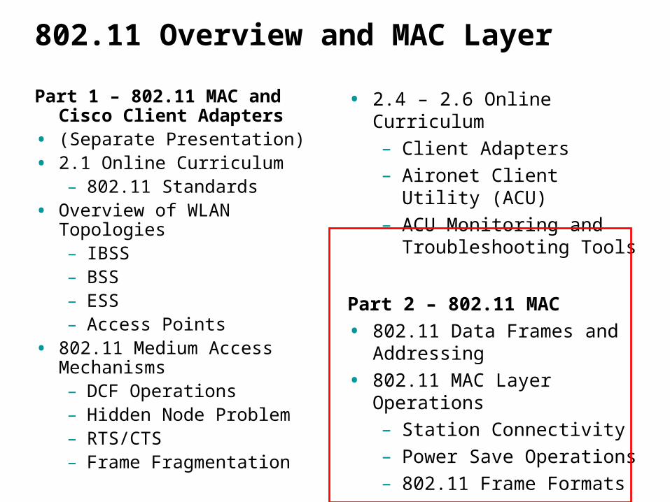
802.11 Frames – This isn’t Ethernet!
802.11 Frames
• Data Frames (most are PCF)
– Data
– Null data
– Data+CF+Ack
– Data+CF+Poll
– Data+CF+Ac+CF+Poll
– CF-Ack
– CF-Poll
– CF-Cak+CF-Poll
• Control Frames
– RTS
– CTS
– ACK
– CF-End
– CF-End+CF-Ack
• Management Frames
– Beacon
– Probe Request
– Probe Response
– Authentication
– Deauthentication
– Association Request
– Association Response
– Reassociation Request
– Reassociation Response
– Disassociation
– Announcement Traffic Indication
802.11 Data Frames and Addressing
802.11 MAC Addressing
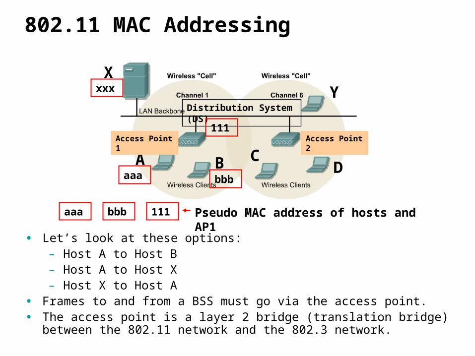
• Let’s look at these options:– Host A to Host B– Host A to Host X– Host X to Host A
• Frames to and from a BSS must go via the access point.• The access point is a layer 2 bridge (translation bridge) between the 802.11
network and the 802.3 network.
Distribution System (DS)
A B CD
Access Point 1 Access Point 2
XY
aaa bbb 111 Pseudo MAC address of hosts and AP1
aaa bbb
xxx
111

802.11 MAC Addressing
• Each BSS is assigned a BSSID. – Not to be confused with SSID or ESSID.
• BSSID – 48 bit identifier which distinguishes it from other BSSs in the network.
• Some BSSs may overlap and the APs need to know which AP the frame is for.
• In a BSS, the BSSID is the MAC address of the wireless interface, I.e. the MAC address of the AP - wireless (translating) bridge.
• Remember, normal switches (bridges) may have MAC addresses, but these addresses are only used for management purposes and not for layer 2 frame forwarding (addressing).
Distribution System (DS)
A B CD
Access Point 1 Access Point 2
XY
General 802.11 Frame aaa bbb
xxx
The BSSID111
802.11 MAC Addressing
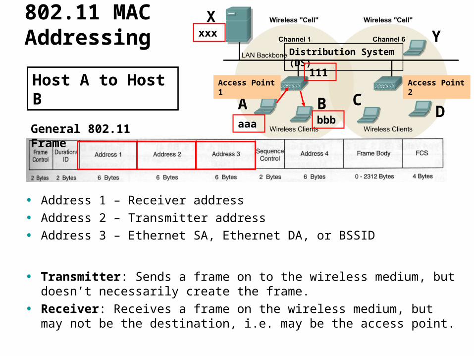
• Address 1 – Receiver address
• Address 2 – Transmitter address
• Address 3 – Ethernet SA, Ethernet DA, or BSSID
• Transmitter: Sends a frame on to the wireless medium, but doesn’t necessarily create the frame.
• Receiver: Receives a frame on the wireless medium, but may not be the destination, i.e. may be the access point.
Distribution System (DS)
A B CD
Access Point 1 Access Point 2
XY
General 802.11 Frame
Host A to Host B
aaa bbb
xxx
111

802.11 MAC Addressing
• Address 1 – Receiver address
• Address 2 – Transmitter address
• Address 3 – Ethernet SA, Ethernet DA, or BSSID
Distribution System (DS)
A B CD
Access Point 1 Access Point 2
XY
Host A to Host B
aaa bbb
aaa111 bbbHost A to AP 1
AP1 to Host B111bbb aaa
xxx
Trans.Rec.
Rec. Trans.
DA
SA
111
0 0
0 0

802.11 MAC Addressing
Distribution System (DS)
A B CD
Access Point 1 Access Point 2
XY
Host A to Host X
aaa bbb
aaa111 xxx
Host A to AP 1
Host A to AP 1
aaaxxx
802.11 Frame
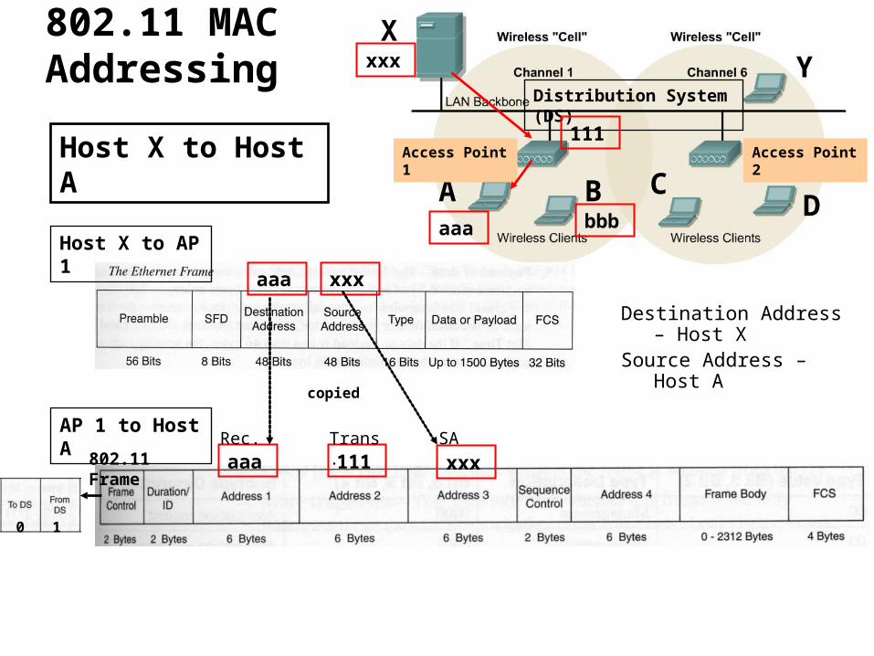
• The Ethernet DA and SA are the source and destination addresses just like on traditional Ethernet networks.– Destination Address – Host X– Source Address – Host A
xxx
Rec. Trans. DA
copied
111
1 0

802.11 MAC Addressing
Distribution System (DS)
A B CD
Access Point 1 Access Point 2
XY
Host A to Host X
aaa bbb
• The AP (bridge) knows which MAC address on on its wireless interface and maintains a table with those MAC addresses. (from the Association process – later)
• When the AP receives an 802.11 frame, it examines the Address 3 address. • If Address 3 is not in its table of wireless MACs it knows it needs to translate the
frame to an Ethernet frame.• The AP copies the Address 3 address to the Ethernet Destination Address, and
Address 2 (Transmitter address) is copied to the Ethernet Source Address.
xxx
aaa111 xxx
Host A to AP 1
802.11 FrameRec. Trans. DA
Host A to AP 1aaaxxx
copied
111
1 0

802.11 MAC Addressing
Distribution System (DS)
A B CD
Access Point 1 Access Point 2
XY
Host X to Host A
aaa bbb
xxx
111
802.11 MAC Addressing
Distribution System (DS)
A B CD
Access Point 1 Access Point 2
XY
Host X to Host A
aaa bbb
aaa 111 xxx
AP 1 to Host A
802.11 Frame
Destination Address – Host X
Source Address – Host A
xxx
Host X to AP 1
aaa xxx
SARec. Trans.
copied
111
0 1

802.11 MAC Layer Operations
Station Connectivity
Power Save Operations

Station Connectivity
• Earlier we stated, at a minimum a client station and the access point must be configured to be using the same SSID.
• How does the client find these APs?• Before connecting to any network, you must find it.• Ethernet, the cable does that for you, but of course there is no cable
with wireless.• There are various applications and utilities that will do it, but what is
actually happening in the 802.11 MAC operations?• Let’s take a look…

Station Connectivity
• Station connectivity is an explanation of how 802.11 stations select and communicate with APs.
State 1 Unauthenticated
Unassociated
State 2 Authenticated Unassociated
State 3 Authenticated
Associated
Successful Authentication
Successful Association
Deauthentication Disassociation

Station Connectivity
• We will look at three processes:– Probe Process (or scanning)– The Authentication Process– The Association Process
• Only after a station has both authenticated and associated with the access point can it use the Distribution System (DS) services and communicate with devices beyond the access point.
State 1 Unauthenticated
Unassociated
State 2 Authenticated Unassociated
State 3 Authenticated
Associated
Successful Authentication
Successful Association
Deauthentication Disassociation
Probe process
Authentication process
Association process
Station Connectivity – Probe Process
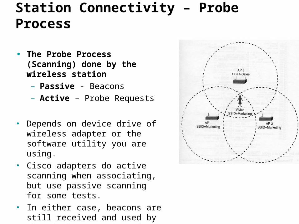
• The Probe Process (Scanning) done by the wireless station– Passive - Beacons– Active – Probe Requests
• Depends on device drive of wireless adapter or the software utility you are using.
• Cisco adapters do active scanning when associating, but use passive scanning for some tests.
• In either case, beacons are still received and used by the wireless stations for other things besides scanning (coming).

Station Connectivity – Passive Scanning
• Passive Scanning– Saves battery power– Station moves to each channel and
waits for Beacon frames from the AP.
– Records any beacons received.• Beacon frames allow a station to find
out every thing it needs to begin communications with the AP including:– SSID– Supported Rates
• Kismet/KisMAC uses passive scanning
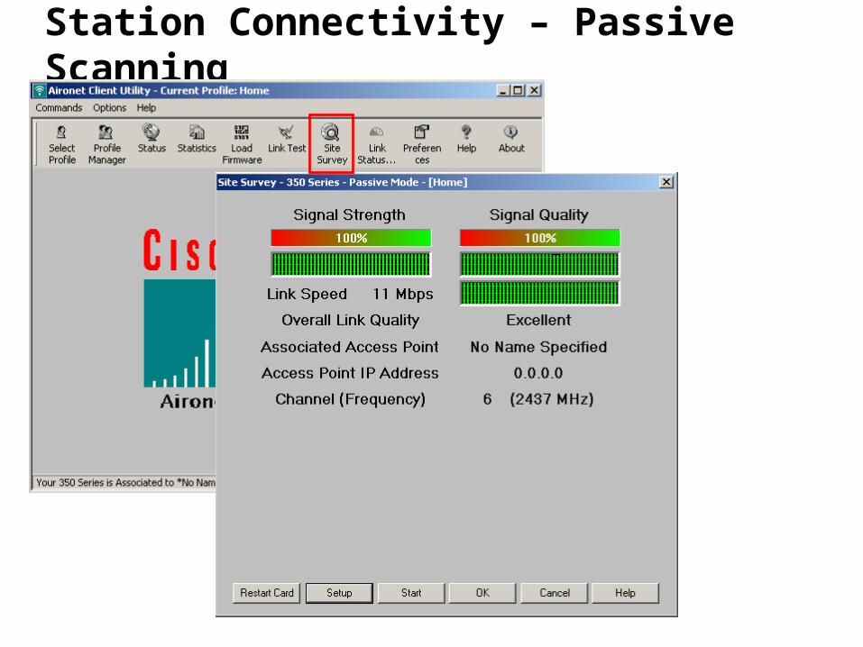
Station Connectivity – Passive Scanning

Station Connectivity – Passive Scanning
Note: Most of these beacons are received via normal operations and not through passive scanning.

Station Connectivity – Passive Scanning
• Passive scans, carried out by listening to Beacons from APs, are not usually displayed by a network analyzer (Ethereal, Airopeek, etc.) but can be.
• Microsecond – millionth of a second• Millisecond – thousandth of a second• A common beacon interval is 100 time units.• Beacon interval is the number of time units between beacon
transmissions.– One unit of time is 1 millisecond.– A beacon interval of 100 is equivalent to 100 milliseconds or 0.1
seconds.– That would be 10 beacons per second.
Station Connectivity – Passive Scanning
• AP features (options)– The SSID can be “hidden” or “cloaked” in the beacon frame (can
be done on Cisco APs)• From some mailing lists:
– “SSID cloaking and beacon hiding isn't necessarily a bad thing, but too many places use it as the only protection because it leads to a false sense of security.”
– “Obscurity != security. Too many companies blindly trust that no beaconing or hiding their SSID means they're automatically safe.”
Station Connectivity – Active Scanning
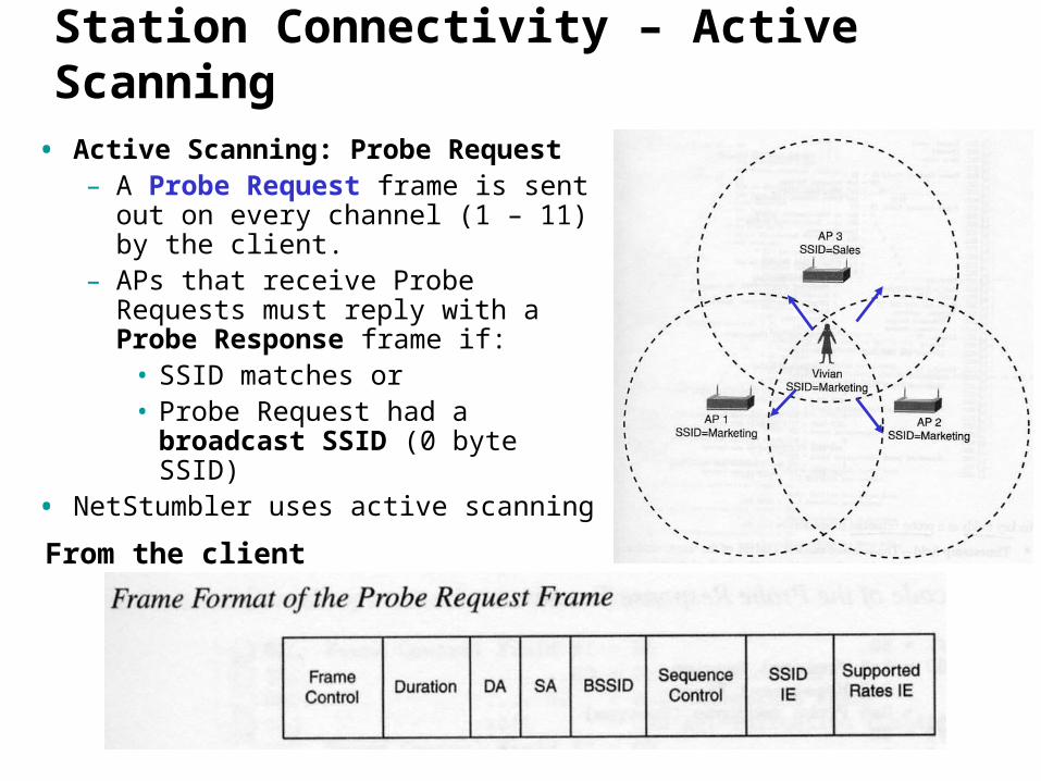
• Active Scanning: Probe Request– A Probe Request frame is sent out
on every channel (1 – 11) by the client.
– APs that receive Probe Requests must reply with a Probe Response frame if:
• SSID matches or• Probe Request had a broadcast
SSID (0 byte SSID)• NetStumbler uses active scanning
From the client
Station Connectivity – Active Scanning
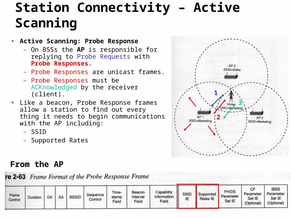
• Active Scanning: Probe Response– On BSSs the AP is responsible for
replying to Probe Requests with Probe Responses.
– Probe Responses are unicast frames.– Probe Responses must be
ACKnowledged by the receiver (client).• Like a beacon, Probe Response frames
allow a station to find out every thing it needs to begin communications with the AP including:– SSID– Supported Rates
1
2
3
From the AP

Station Connectivity
• Access Points can be configured whether or not to allow clients with broadcast SSIDs to continue the connectivity process.– If there is no authentication on the AP, then the client will most likely
“associate” and be on their network! • Cisco APs use a default SSID of tsunami known as the “guest mode” SSID.
(coming) • Unless this feature is disabled or authentication is enabled, anyone can easily
associate with your AP and access your network (or the Internet).
Probe Request Broadcast (no) SSID Probe Response
SSID = tsunamiACK
No SSID
Hey, I didn’t do anything and I am on the Internet!

Authentication Process
• On a wired network, authentication is implicitly provided by the physical cable from the PC to the switch.
• Authentication is the process to ensure that stations attempting to associate with the network (AP) are allowed to do so.
• 802.11 specifies two types of authentication:– Open-system– Shared-key (makes use of WEP)
Authentication Process – Open-System
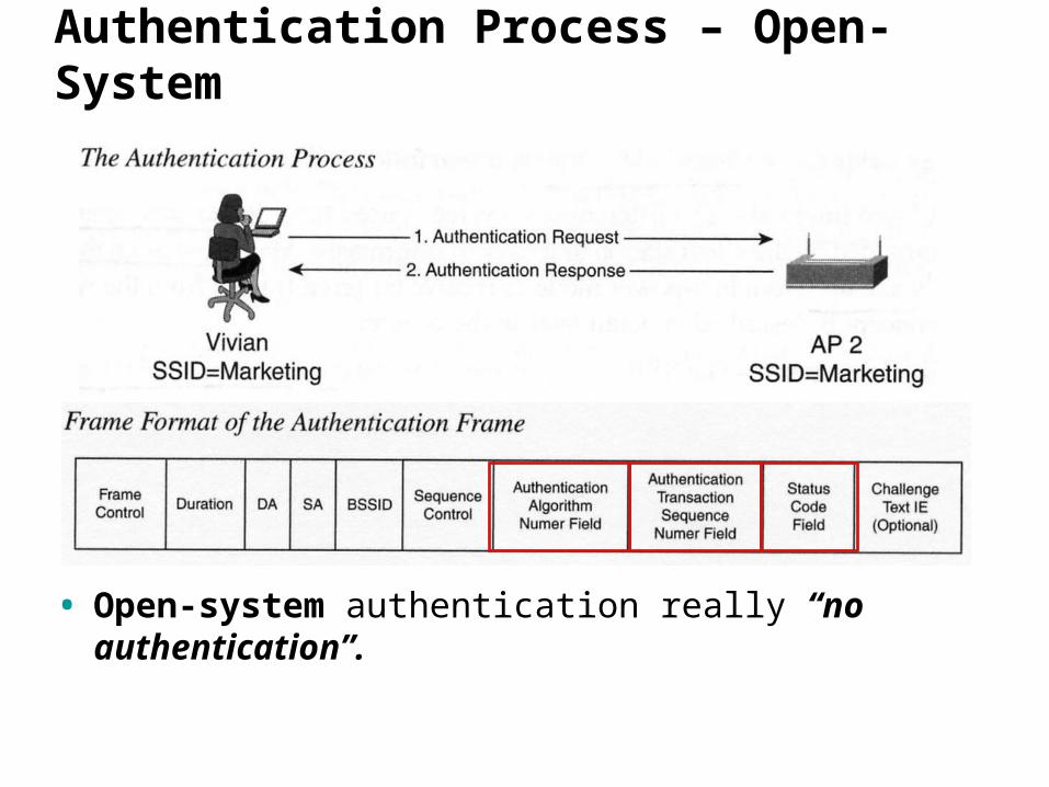
• Open-system authentication really “no authentication”.
Authentication Process – Shared-Key
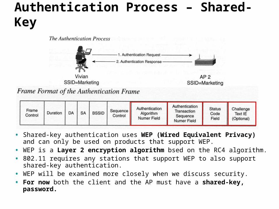
• Shared-key authentication uses WEP (Wired Equivalent Privacy) and can only be used on products that support WEP.
• WEP is a Layer 2 encryption algorithm bsed on the RC4 algorithm.• 802.11 requires any stations that support WEP to also support shared-
key authentication.• WEP will be examined more closely when we discuss security.• For now both the client and the AP must have a shared-key, password.

Authentication Process
• We’ll look at the configuration of the client and AP later!
• Example of open-system authentication.
• Note: On “some” systems you can configure authentication (WEP) and WEP encryption separately. On the ACU you can have open-system authentication and also have WEP encryption. However, if you have Shared-key (WEP) authentication, you must use WEP encryption.
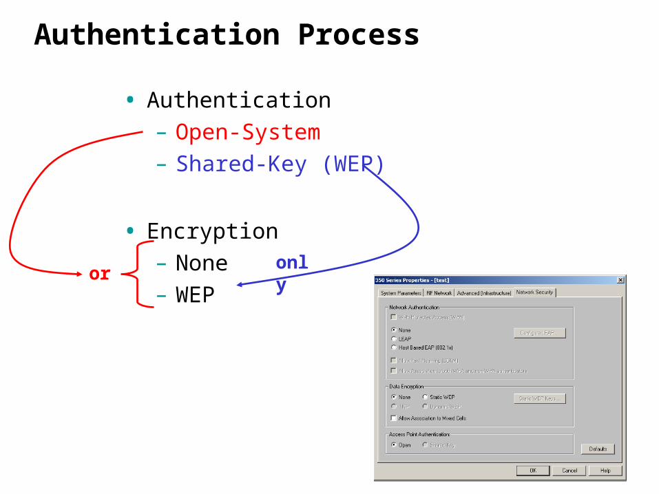
Authentication Process
• Authentication– Open-System– Shared-Key (WEP)
• Encryption– None– WEP
oronly
Association Process
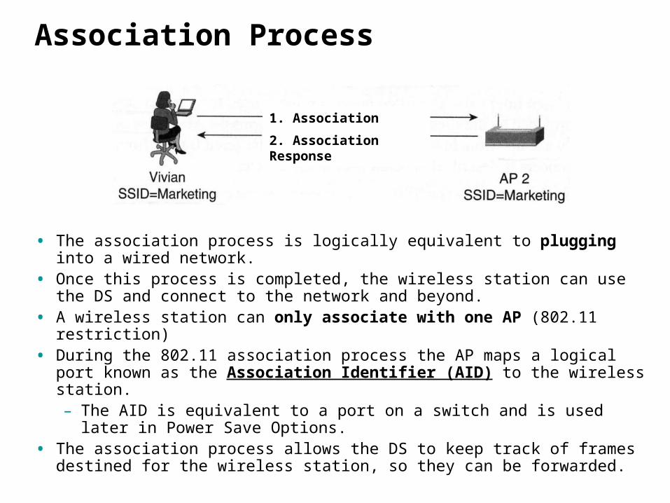
• The association process is logically equivalent to plugging into a wired network.
• Once this process is completed, the wireless station can use the DS and connect to the network and beyond.
• A wireless station can only associate with one AP (802.11 restriction)• During the 802.11 association process the AP maps a logical port
known as the Association Identifier (AID) to the wireless station.– The AID is equivalent to a port on a switch and is used later in
Power Save Options.• The association process allows the DS to keep track of frames
destined for the wireless station, so they can be forwarded.
1. Association Request
2. Association Response

Association Process
– At this point the AP adds the source address of the wireless client to its Source Address Table.
– This is how the AP knows to forward frames destined to the client out the wireless interface (802.11) and not the wired interface (802.3/Ethernet).
– The AP usually learns the wireless client’s Source Address sooner, either in the Probe Request or Authentication Request frames, but this is where it “officially” adds the wireless client to it MAC table.


![[Portfolio] Yousif J AlSaleem](https://img.pdfslide.net/doc/110x75/568c3a9a1a28ab0235a6debf/portfolio-yousif-j-alsaleem.jpg)