Embed Size (px)
Citation preview
1Korea Aerospace University Mobile Communications Lab.
CH 4. Principle of Code Division Multiple Access
2Korea Aerospace University Mobile Communications Lab.
Contents
What is CDMA? Basic Concept of Spread Spectrum Techniques Spreading Codes Used for CDMA
Walsh Codes Pseudo-random Noise (PN) Codes, etc.
Classification of CDMA Systems CDMA Features Summary: CDMA System Benefits
3Korea Aerospace University Mobile Communications Lab.
What is CDMA?
CDMA (Code Division Multiple Access) is a type of multiple access schemes in which each user expands the signal bandwidth in excess of minimum necessary to send the information and shares the same spectrum at the same time.
In CDMA, each user can be differentiated by its own unique spreading code.
Spreading a signal in CDMA is, in usual, accomplished by means of PN (pseudo-random noise) codes, which are generated by using a linear feedback shift register (LFSR).
4Korea Aerospace University Mobile Communications Lab.
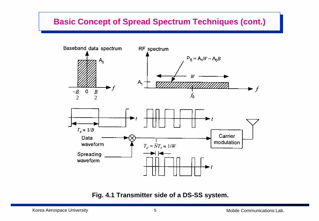
Basic Concept of Spread Spectrum Techniques [4]
Definition Spread-spectrum is a radio transmission technology in which the signal
bandwidth is expanded in excess of the minimum necessary to send the information.
Primarily used for military purpose due to its intrinsic natures such as low probability of detection and robustness to jamming, etc.
Since 1990s, applied to commercial mobile communication systems called CDMA.
Types of spread-spectrum systems; direct-sequence spread spectrum (DS-SS), frequency-hopping spread spectrum (FH-SS), hybrid type spread-spectrum, and chirp spread-spectrum systems.
5Korea Aerospace University Mobile Communications Lab.
Basic Concept of Spread Spectrum Techniques (cont.)
Fig. 4.1 Transmitter side of a DS-SS system.
22
1
6Korea Aerospace University Mobile Communications Lab.
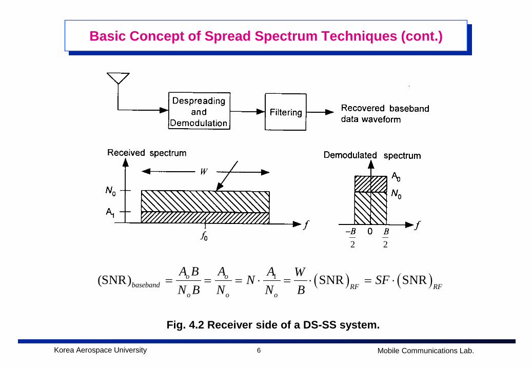
Basic Concept of Spread Spectrum Techniques (cont.)
Fig. 4.2 Receiver side of a DS-SS system.
( ) ( )1(SNR) SNR SNRo obaseband RF RF
o o o
A B A A WN SFN B N N B
= = = ⋅ = ⋅ = ⋅
22
Noise
7Korea Aerospace University Mobile Communications Lab.
Spreading Codes for CDMA [1],[2]
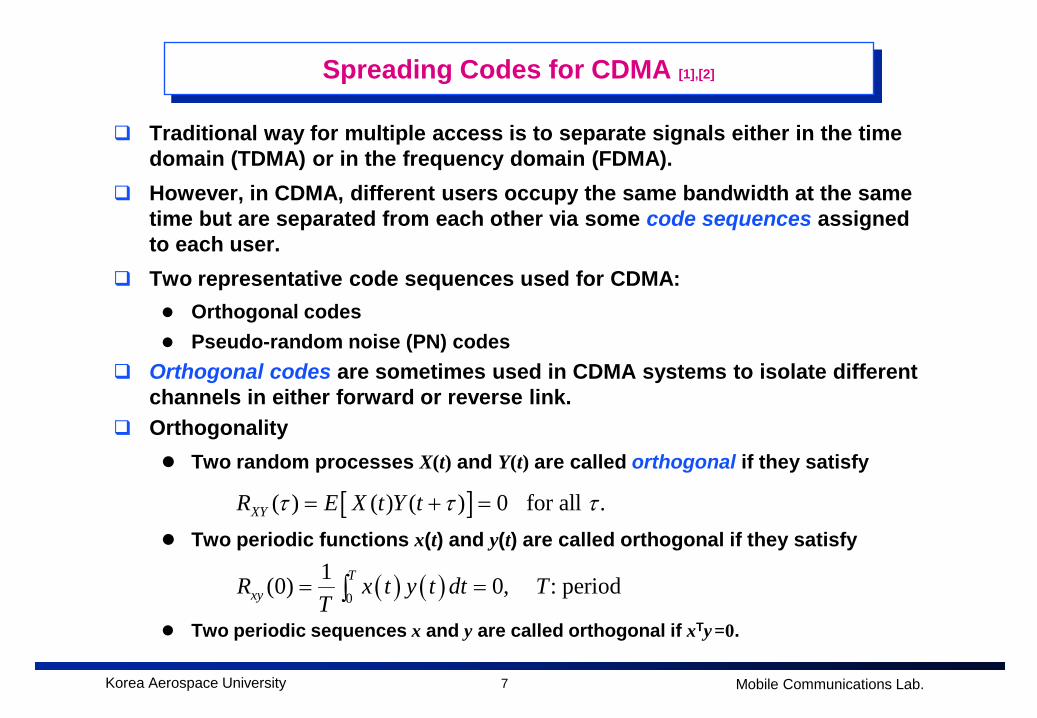
Traditional way for multiple access is to separate signals either in the time domain (TDMA) or in the frequency domain (FDMA).
However, in CDMA, different users occupy the same bandwidth at the same time but are separated from each other via some code sequences assigned to each user.
Two representative code sequences used for CDMA: Orthogonal codes Pseudo-random noise (PN) codes
Orthogonal codes are sometimes used in CDMA systems to isolate different channels in either forward or reverse link.
Orthogonality Two random processes X(t) and Y(t) are called orthogonal if they satisfy
Two periodic functions x(t) and y(t) are called orthogonal if they satisfy
Two periodic sequences x and y are called orthogonal if xTy =0.
( ) ( )0
1(0) 0, : period TxyR x t y t dt T
T= =∫
[ ]( ) ( ) ( ) 0 for all . XYR E X t Y tτ τ τ= + =
8Korea Aerospace University Mobile Communications Lab.
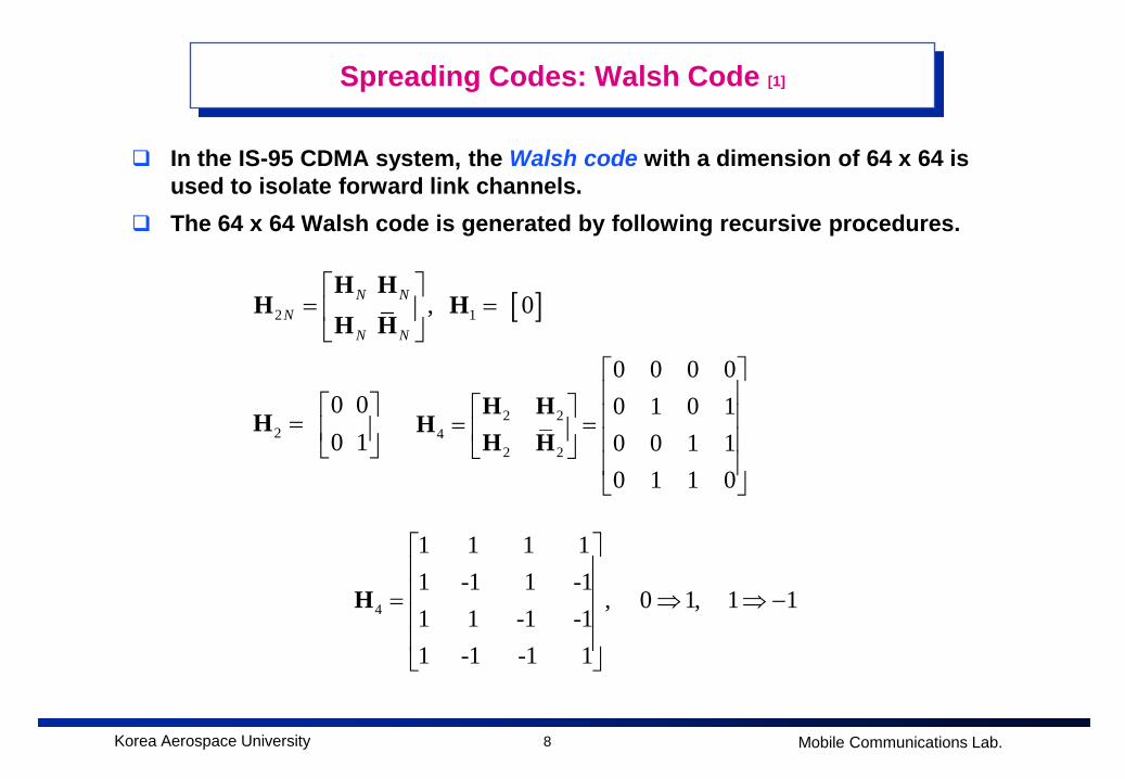
Spreading Codes: Walsh Code [1]
In the IS-95 CDMA system, the Walsh code with a dimension of 64 x 64 is used to isolate forward link channels.
The 64 x 64 Walsh code is generated by following recursive procedures.
[ ]2 1
, 0
N N
NN N
= =
H HH H
H H
2 24
2 2
0 0 0 00 1 0 10 0 1 10 1 1 0
= =
H HH
H H2
0 0
0 1
=
H
4
1 1 1 11 -1 1 -1
, 0 1, 1 11 1 -1 -11 -1 -1 1
= ⇒ ⇒ −
H
9Korea Aerospace University Mobile Communications Lab.
Spreading Codes: Walsh Code (cont.)
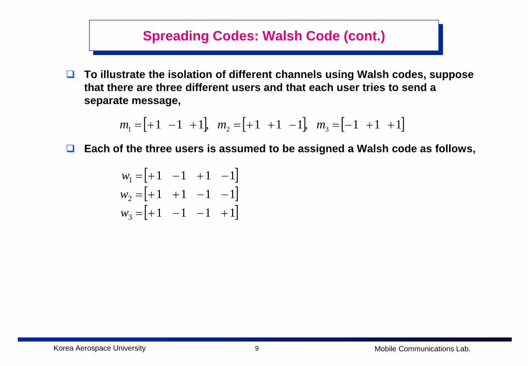
To illustrate the isolation of different channels using Walsh codes, suppose that there are three different users and that each user tries to send a separate message,
Each of the three users is assumed to be assigned a Walsh code as follows,
[ ] [ ] [ ]1 1 1 ,1 1 1 ,1 1 1 321 ++−=−++=+−+= mmm
[ ][ ][ ]1111
11111111
3
2
1
+−−+=−−++=−+−+=
www
10Korea Aerospace University Mobile Communications Lab.
Spreading Codes: Walsh Code (cont.)
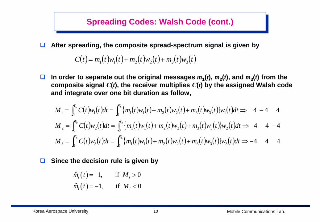
After spreading, the composite spread-spectrum signal is given by
In order to separate out the original messages m1(t), m2(t), and m3(t) from the composite signal C(t), the receiver multiplies C(t) by the assigned Walsh code and integrate over one bit duration as follow,
Since the decision rule is given by
( ) ( ) ( ) ( ) ( ) ( ) ( )twtmtwtmtwtmtC 332211 ++=
( ) ( ) ( ) ( ) ( ) ( ) ( ) ( ){ } ( )
( ) ( ) ( ) ( ) ( ) ( ) ( ) ( ){ } ( )
( ) ( ) ( ) ( ) ( ) ( ) ( ) ( ){ } ( ) 4 4 4
4 4 4
4 4 4
0 33322110 33
0 23322110 22
0 13322110 11
−⇒++==
−⇒++==
−⇒++==
∫∫∫∫∫∫
bb
bb
bb
TT
TT
TT
dttwtwtmtwtmtwtmdttwtCM
dttwtwtmtwtmtwtmdttwtCM
dttwtwtmtwtmtwtmdttwtCM
( )( )
ˆ 1, if 0ˆ 1, if 0
i i
i i
m t M
m t M
= >
= − <
11Korea Aerospace University Mobile Communications Lab.
Spreading Codes: Walsh Code (cont.)
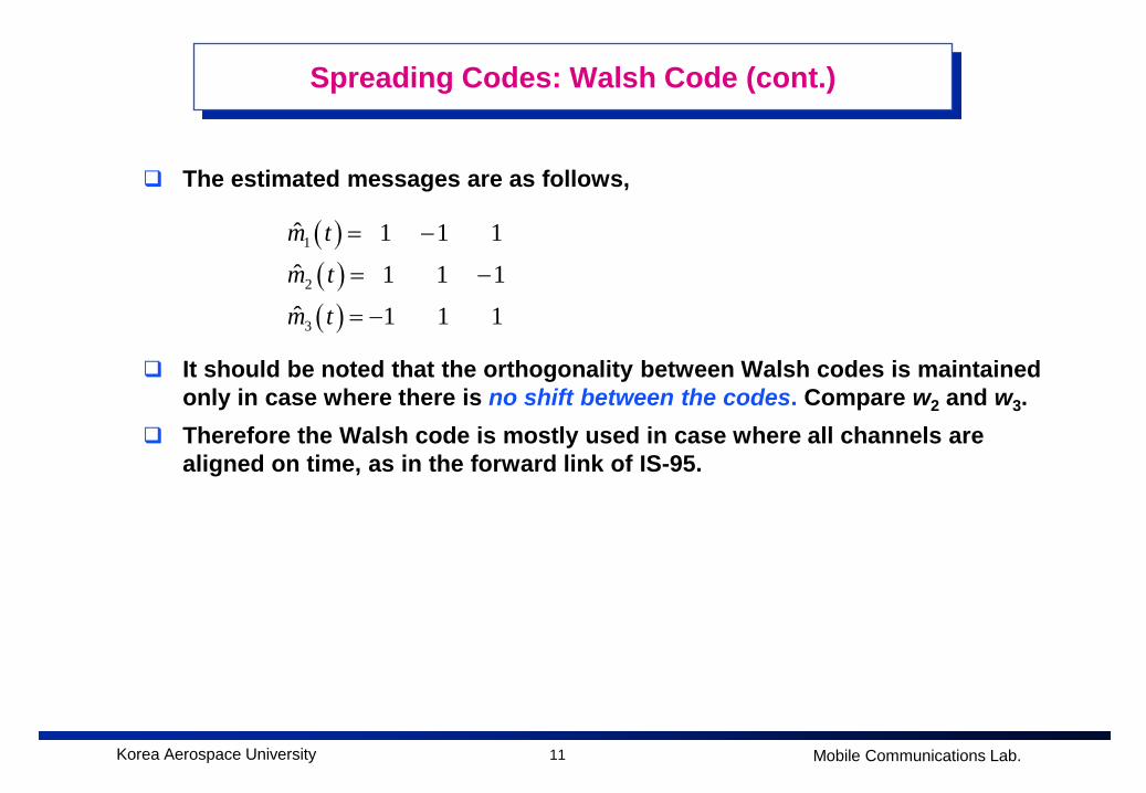
The estimated messages are as follows,
It should be noted that the orthogonality between Walsh codes is maintained only in case where there is no shift between the codes. Compare w2 and w3.
Therefore the Walsh code is mostly used in case where all channels are aligned on time, as in the forward link of IS-95.
( )( )( )
1
2
3
ˆ 1 1 1 ˆ 1 1 1ˆ 1 1 1
m t
m t
m t
= −
= −
= −
12Korea Aerospace University Mobile Communications Lab.
Spreading Codes: PN Code [1],[2]
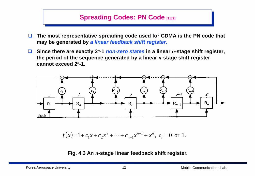
The most representative spreading code used for CDMA is the PN code that may be generated by a linear feedback shift register.
Since there are exactly 2n-1 non-zero states in a linear n-stage shift register, the period of the sequence generated by a linear n-stage shift register cannot exceed 2n-1.
Fig. 4.3 An n-stage linear feedback shift register.
( ) .1or 0 ,1 11
221 =+++++= −
− inn
n cxxcxcxcxf
13Korea Aerospace University Mobile Communications Lab.
Spreading Codes: PN Code (cont.)
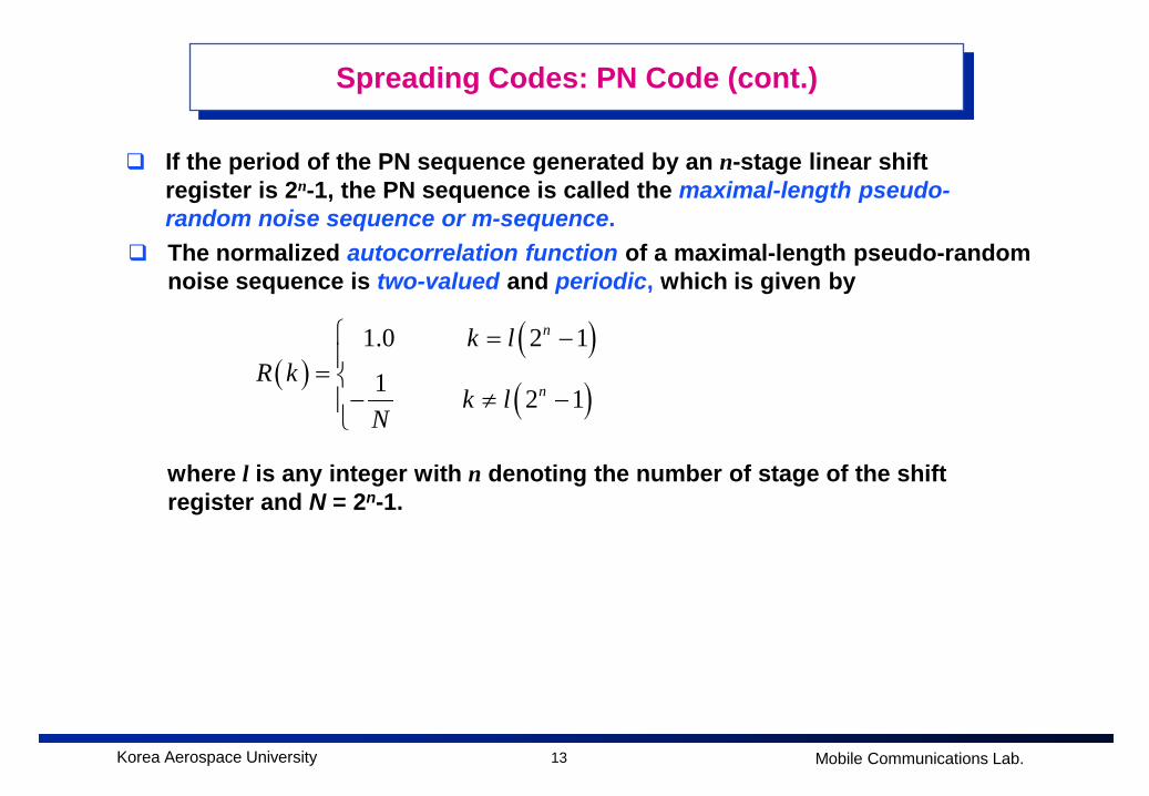
If the period of the PN sequence generated by an n-stage linear shift register is 2n-1, the PN sequence is called the maximal-length pseudo-random noise sequence or m-sequence.
The normalized autocorrelation function of a maximal-length pseudo-random noise sequence is two-valued and periodic, which is given by
where l is any integer with n denoting the number of stage of the shift register and N = 2n-1.
( )( )( )
1.0 2 1
1 2 1
n
n
k lR k
k lN
= −= − ≠ −
14Korea Aerospace University Mobile Communications Lab.
Spreading Codes: PN Code (cont.)
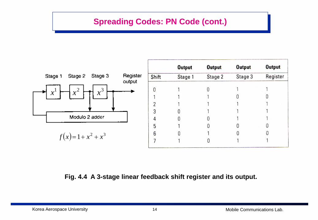
Fig. 4.4 A 3-stage linear feedback shift register and its output.
1x 2x 3x
( ) 321 xxxf ++=
15Korea Aerospace University Mobile Communications Lab.
Spreading Codes: PN Code (cont.)
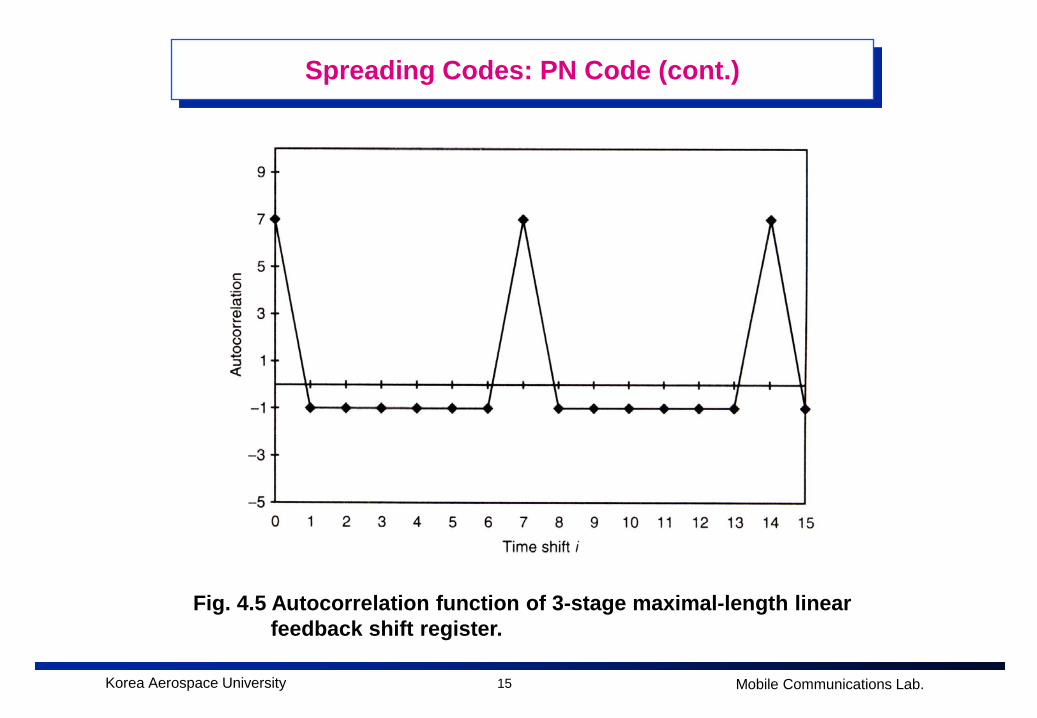
Fig. 4.5 Autocorrelation function of 3-stage maximal-length linear feedback shift register.
16Korea Aerospace University Mobile Communications Lab.
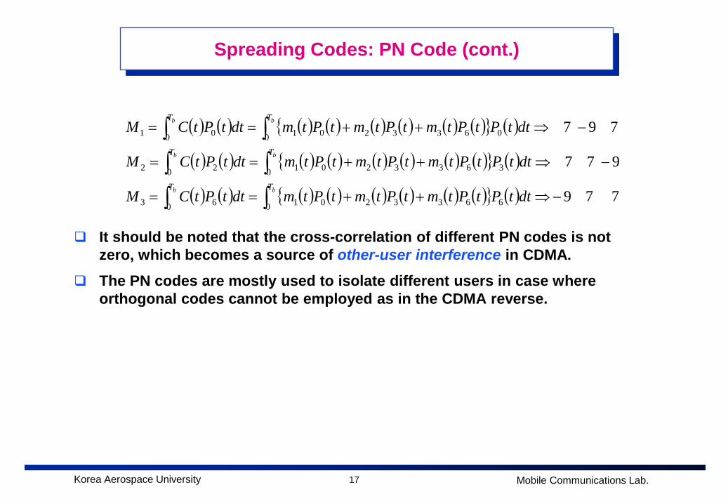
Spreading Codes: PN Code (cont.)
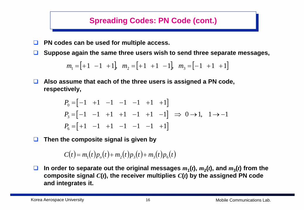
PN codes can be used for multiple access. Suppose again the same three users wish to send three separate messages,
Also assume that each of the three users is assigned a PN code, respectively,
Then the composite signal is given by
In order to separate out the original messages m1(t), m2(t), and m3(t) from the composite signal C(t), the receiver multiplies C(t) by the assigned PN code and integrates it.
[ ] [ ] [ ]1 1 1 ,1 1 1 ,1 1 1 321 ++−=−++=+−+= mmm
[ ][ ][ ]
0
3
6
1 1 1 1 1 1 1
1 1 1 1 1 1 1 0 1, 1 1
1 1 1 1 1 1 1
P
P
P
= − + − − − + +
= − − + + − + − ⇒ → → −
= + − + − − − +
( ) ( ) ( ) ( ) ( ) ( ) ( )tptmtptmtptmtC o 63321 ++=
17Korea Aerospace University Mobile Communications Lab.
Spreading Codes: PN Code (cont.)
It should be noted that the cross-correlation of different PN codes is not zero, which becomes a source of other-user interference in CDMA.
The PN codes are mostly used to isolate different users in case where orthogonal codes cannot be employed as in the CDMA reverse.
( ) ( ) ( ) ( ) ( ) ( ) ( ) ( ){ } ( )
( ) ( ) ( ) ( ) ( ) ( ) ( ) ( ){ } ( )
( ) ( ) ( ) ( ) ( ) ( ) ( ) ( ){ } ( ) 7 7 9
9 7 7
7 9 7
0 66332010 63
0 36332010 22
0 06332010 01
−⇒++==
−⇒++==
−⇒++==
∫∫∫∫∫∫
bb
bb
bb
TT
TT
TT
dttPtPtmtPtmtPtmdttPtCM
dttPtPtmtPtmtPtmdttPtCM
dttPtPtmtPtmtPtmdttPtCM
18Korea Aerospace University Mobile Communications Lab.
Classification of CDMA Systems
CDMA systems can be classified into the synchronous CDMA system and the asynchronous CDMA system.
Synchronous CDMA System All base stations are synchronized with each other by using the time
information obtained from GPS satellites. All base stations use the same PN code with different phase shifts so that the
initial synchronization at the mobile is relatively easy. IS-95 and cdma2000 systems
Asynchronous CDMA System Unlike synchronous systems, GPS satellites are not used for synchronization
while base stations are roughly synchronized with each other by using a network clock.
Each base station should employ a different PN code ==> Initial synchronization requires a long time and a special synchronization circuit so called the matched filter should be used.
WCDMA system
19Korea Aerospace University Mobile Communications Lab.
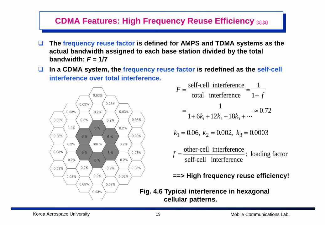
CDMA Features: High Frequency Reuse Efficiency [1],[2]
The frequency reuse factor is defined for AMPS and TDMA systems as the actual bandwidth assigned to each base station divided by the total bandwidth: F = 1/7
In a CDMA system, the frequency reuse factor is redefined as the self-cell interference over total interference.
1 2 3
self-cell interference 1total interference 1
1 0.721 6 12 18
Ff
k k k
= =+
= ≈+ + + +
k k k1 2 30 06 0 002 0 0003= = =. , . , . 100 %
6 %
6 %
6 %
6 %
6 %
6 %
0.2%
0.2%
0.2%
0.2%
0.2%
0.2%
0.2%
0.2%
0.2%
0.2%
0.2%
0.2%
0.03%
0.03%
0.03%
0.03%
0.03%
0.03%
0.03%
0.03%
0.03%
0.03%
0.03%
0.03%
0.03%
0.03%
0.03%
0.03%
0.03%
0.03%
Fig. 4.6 Typical interference in hexagonal cellular patterns.
==> High frequency reuse efficiency!
other-cell interference : loading factorself-cell interference
f =

20Korea Aerospace University Mobile Communications Lab.
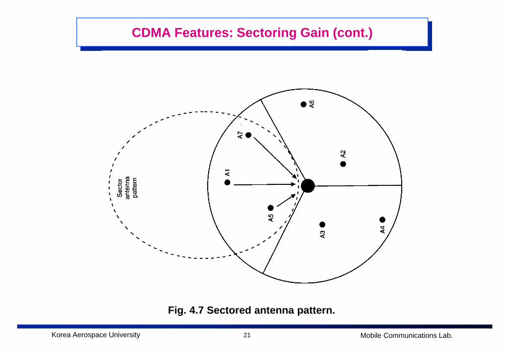
CDMA Features: Sectoring Gain [1],[2]
The interference at the base station can be reduced significantly if the cell is sectored.
Three sector antenna is typically used so that each sector receives the signals coming over only 120 degrees as shown in Fig. 4.7.
This arrangement decreases the interference by a factor of approximately 1/3, meaning that sectoring gain Ga is 3.
If the cell is sectored to six sectors, then the interference is decreased by a factor of approximately 1/6.
In actual, however, the sectoring gain becomes about 2.5 for three-sector antenna and 5 for six-sector antenna due to overlapping of antenna beam-pattern.
21Korea Aerospace University Mobile Communications Lab.
CDMA Features: Sectoring Gain (cont.)
Fig. 4.7 Sectored antenna pattern.
22Korea Aerospace University Mobile Communications Lab.
CDMA Features: Voice Activity Gain [1],[2]
The voice activity is defined as the actual talking time normalized by the user’s overall holding time in voice communications.
CDMA systems can reduce interference effectively by using the voice activity in such a way that the system does not transmit any signal while a user is not actually talking.
The voice activity is about 0.4 so that the channel capacity can be increased up to 2.5 times by simply utilizing the voice activity.
23Korea Aerospace University Mobile Communications Lab.
CDMA Features: Power Control [1],[2]
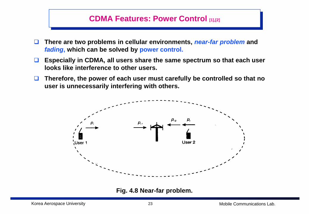
There are two problems in cellular environments, near-far problem and fading, which can be solved by power control.
Especially in CDMA, all users share the same spectrum so that each user looks like interference to other users.
Therefore, the power of each user must carefully be controlled so that no user is unnecessarily interfering with others.
Fig. 4.8 Near-far problem.
24Korea Aerospace University Mobile Communications Lab.
CDMA Features: Power Control (cont.)
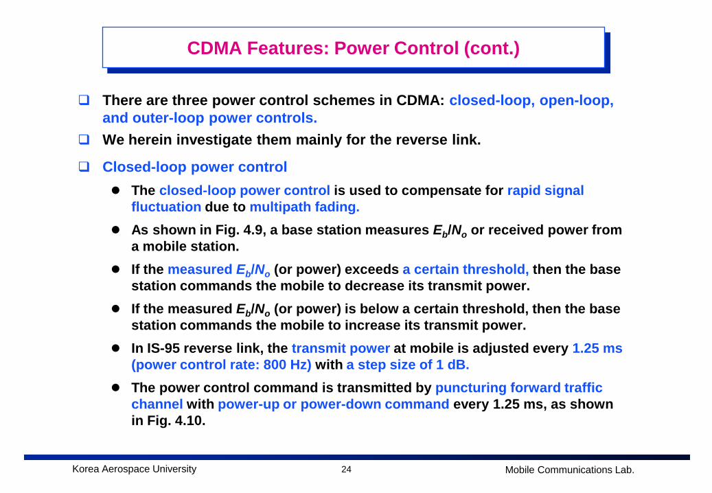
There are three power control schemes in CDMA: closed-loop, open-loop, and outer-loop power controls.
We herein investigate them mainly for the reverse link.
Closed-loop power control The closed-loop power control is used to compensate for rapid signal
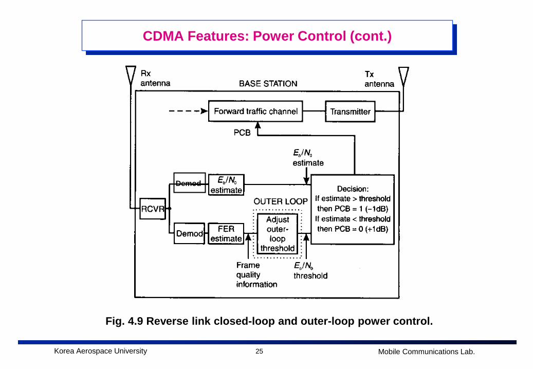
fluctuation due to multipath fading. As shown in Fig. 4.9, a base station measures Eb/No or received power from
a mobile station. If the measured Eb/No (or power) exceeds a certain threshold, then the base
station commands the mobile to decrease its transmit power. If the measured Eb/No (or power) is below a certain threshold, then the base
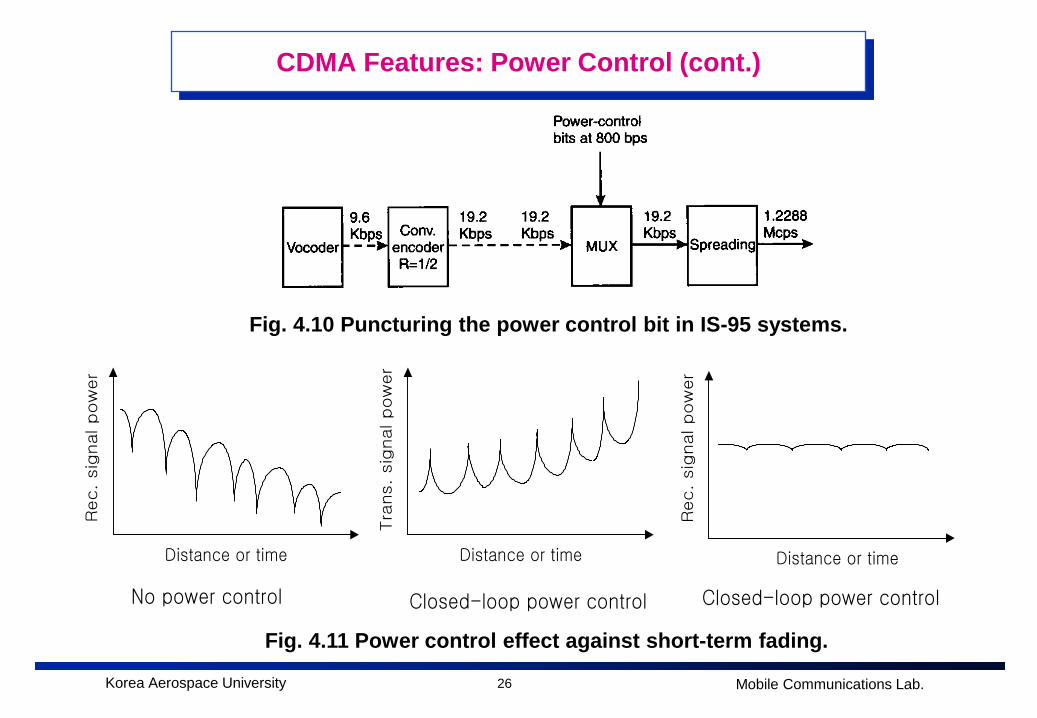
station commands the mobile to increase its transmit power. In IS-95 reverse link, the transmit power at mobile is adjusted every 1.25 ms
(power control rate: 800 Hz) with a step size of 1 dB. The power control command is transmitted by puncturing forward traffic
channel with power-up or power-down command every 1.25 ms, as shown in Fig. 4.10.
25Korea Aerospace University Mobile Communications Lab.
CDMA Features: Power Control (cont.)
Fig. 4.9 Reverse link closed-loop and outer-loop power control.
Demod
26Korea Aerospace University Mobile Communications Lab.
CDMA Features: Power Control (cont.)
Distance or time Distance or time
Rec.
sig
nal pow
er
Rec.
sig
nal pow
er
No power control Closed-loop power control
Distance or time
Tra
ns.
sig
nal pow
er
Closed-loop power control
Fig. 4.11 Power control effect against short-term fading.
Fig. 4.10 Puncturing the power control bit in IS-95 systems.
27Korea Aerospace University Mobile Communications Lab.
CDMA Features: Power Control (cont.)
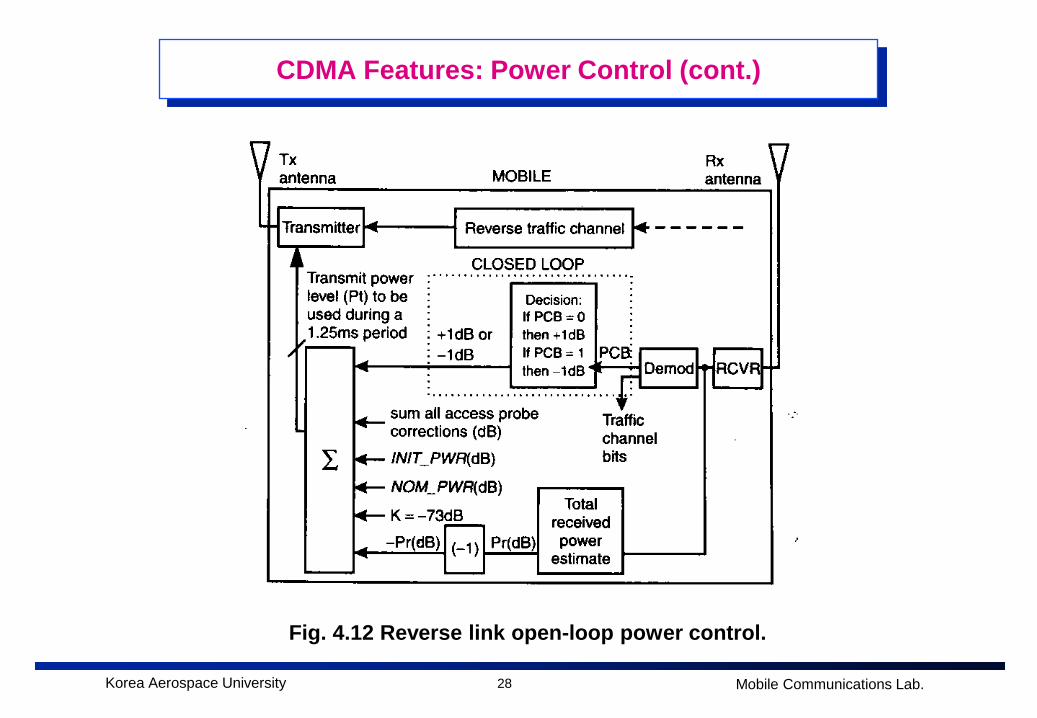
Open-loop power control The open-loop power control is used to compensate for a large fluctuation of
the signal due to long-term fading where there is a high correlation between the forward and reverse links.
As shown in Fig. 4.12, a mobile station continuously monitors the received power from the base station and adjusts transmit power in response to the change in received power from base station.
The term open-loop is used in that it is purely a mobile-controlled operationand does not involve the base station at all.
Outer-loop power control In CDMA systems, the quality of link is finally determined by the FER (frame
error rate) or BER (bit error rate). The outer-loop power control is the process to adjust target Eb/No (or
threshold) in response to the FER measurements at the base station, as shown in Fig. 4.9.
That is, if the measured FER at the base station is larger than a certain threshold (10-2 FER for voice for example) for a given target Eb/No (or threshold), then the base station increases the target Eb/No.
Otherwise, the base station decreases the target Eb/No.
28Korea Aerospace University Mobile Communications Lab.
CDMA Features: Power Control (cont.)
Fig. 4.12 Reverse link open-loop power control.
29Korea Aerospace University Mobile Communications Lab.
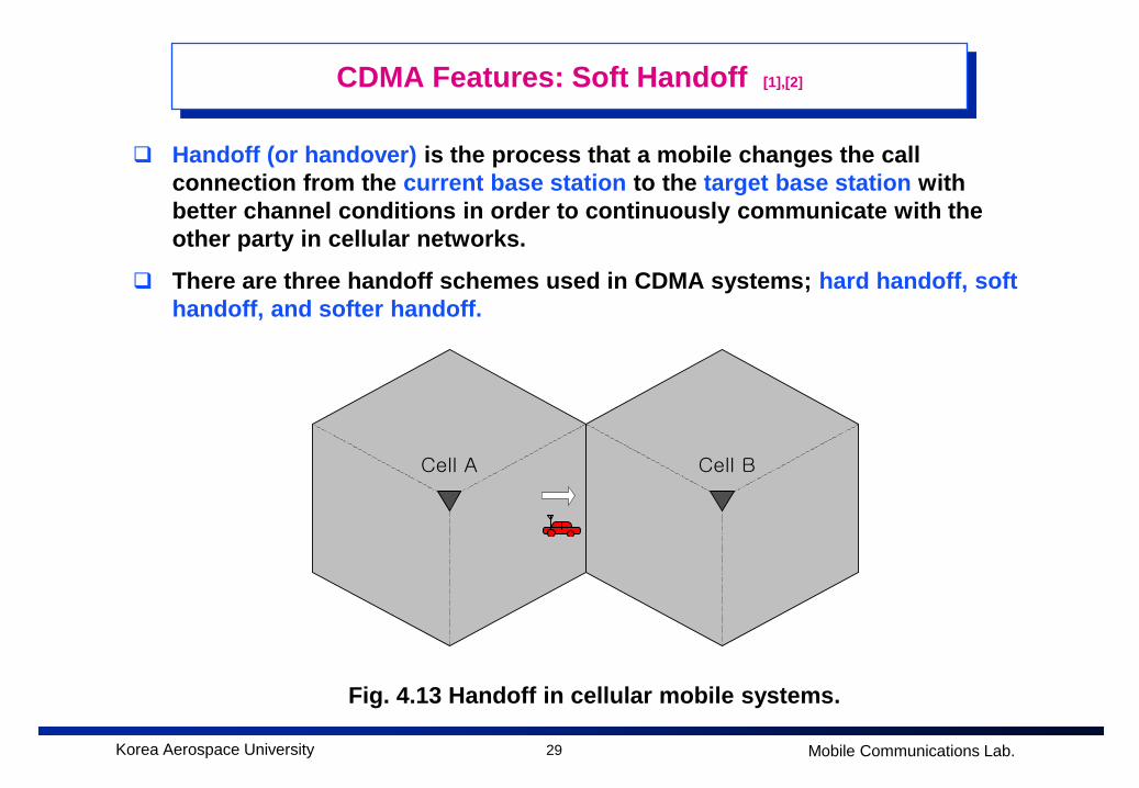
CDMA Features: Soft Handoff [1],[2]
Cell A Cell B
Fig. 4.13 Handoff in cellular mobile systems.
Handoff (or handover) is the process that a mobile changes the call connection from the current base station to the target base station with better channel conditions in order to continuously communicate with the other party in cellular networks.
There are three handoff schemes used in CDMA systems; hard handoff, soft handoff, and softer handoff.
30Korea Aerospace University Mobile Communications Lab.
CDMA Features: Soft Handoff (cont.)
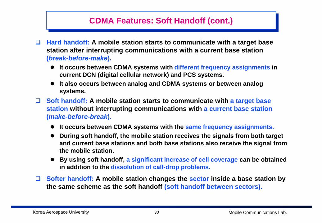
Hard handoff: A mobile station starts to communicate with a target base station after interrupting communications with a current base station (break-before-make). It occurs between CDMA systems with different frequency assignments in
current DCN (digital cellular network) and PCS systems. It also occurs between analog and CDMA systems or between analog
systems. Soft handoff: A mobile station starts to communicate with a target base
station without interrupting communications with a current base station (make-before-break). It occurs between CDMA systems with the same frequency assignments. During soft handoff, the mobile station receives the signals from both target
and current base stations and both base stations also receive the signal from the mobile station.
By using soft handoff, a significant increase of cell coverage can be obtained in addition to the dissolution of call-drop problems.
Softer handoff: A mobile station changes the sector inside a base station by the same scheme as the soft handoff (soft handoff between sectors).
31Korea Aerospace University Mobile Communications Lab.
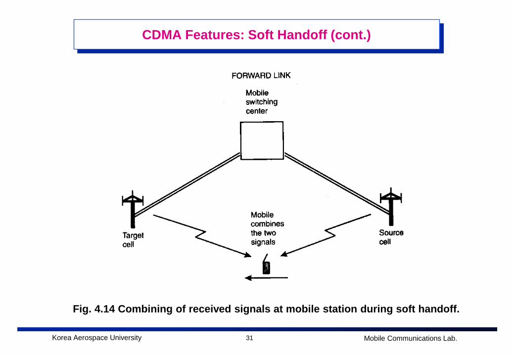
CDMA Features: Soft Handoff (cont.)
Fig. 4.14 Combining of received signals at mobile station during soft handoff.
32Korea Aerospace University Mobile Communications Lab.
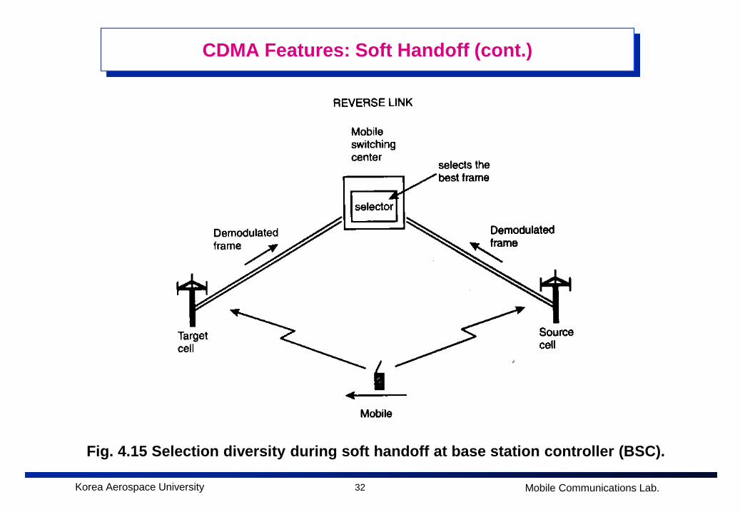
CDMA Features: Soft Handoff (cont.)
Fig. 4.15 Selection diversity during soft handoff at base station controller (BSC).
33Korea Aerospace University Mobile Communications Lab.
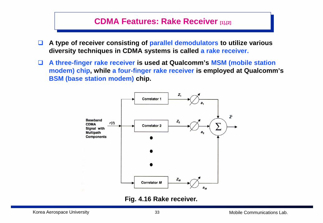
CDMA Features: Rake Receiver [1],[2]
A type of receiver consisting of parallel demodulators to utilize various diversity techniques in CDMA systems is called a rake receiver.
A three-finger rake receiver is used at Qualcomm’s MSM (mobile station modem) chip, while a four-finger rake receiver is employed at Qualcomm’s BSM (base station modem) chip.
Fig. 4.16 Rake receiver.
34Korea Aerospace University Mobile Communications Lab.
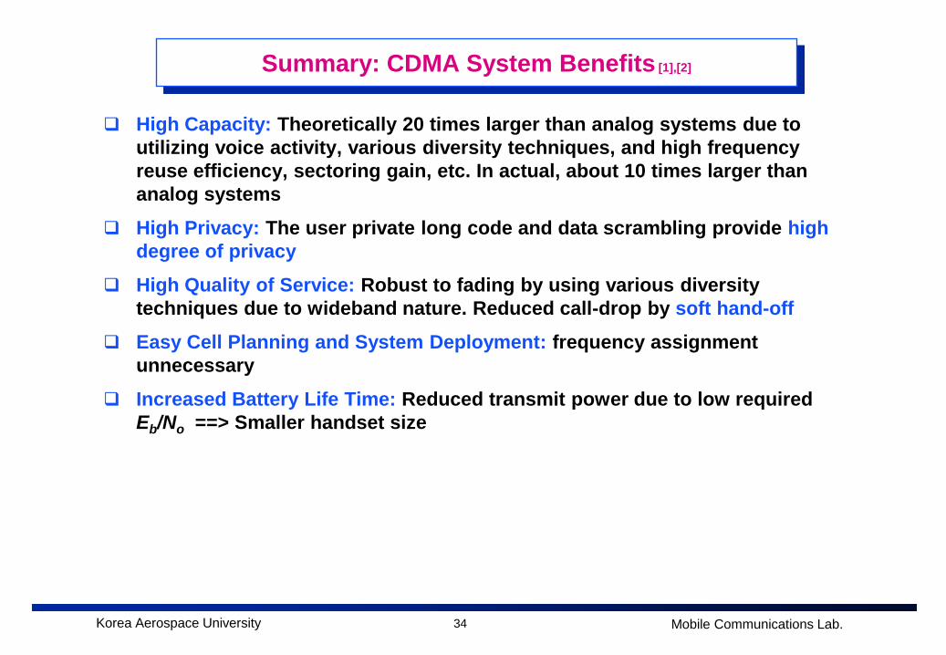
Summary: CDMA System Benefits [1],[2]
High Capacity: Theoretically 20 times larger than analog systems due to utilizing voice activity, various diversity techniques, and high frequency reuse efficiency, sectoring gain, etc. In actual, about 10 times larger than analog systems
High Privacy: The user private long code and data scrambling provide high degree of privacy
High Quality of Service: Robust to fading by using various diversity techniques due to wideband nature. Reduced call-drop by soft hand-off
Easy Cell Planning and System Deployment: frequency assignment unnecessary
Increased Battery Life Time: Reduced transmit power due to low required Eb/No ==> Smaller handset size
35Korea Aerospace University Mobile Communications Lab.
References
1. Samuel C. Yang, CDMA RF System Engineering, Artech House, 1998.
2. Qualcomm, CDMA System Training Handbook-vol. 1, 1993.


![1학기 12주.ppt [호환 모드] - KOCW](https://img.pdfslide.net/doc/110x75/6255c2426b8560665557be79/1-12ppt-kocw.jpg)