Embed Size (px)
DESCRIPTION
Celestial Navigation Book
Citation preview
Chapter 8 CELESTIAL NAVIGATION
Navigation (Advanced) for Mates / Masters Nadeem Anwar
CELESTIAL NAVIGATION The positions and motion of heavenly bodies are predictable. Since the positions of these bodies can be referenced to the earth, the heavenly bodies can be used for navigational purposes.
8.1 THE CELSETIAL SPHERE An imaginary sphere with the earth at its centre and an infinite radius is called the celestial sphere. Its reference marks are linked to earth or the terrestrial sphere. Projection of plane of the equator to the celestial sphere forms the celestial equator. It is also referred to as the equinoctial.
N = Nadir
Pn
Ps
X
ZZenith
Qw
Qe
Pn
Celestial
Equator
Observer's M
eridian
Figure 8.1. Celestial Sphere and Components
Parallel of
Declination
UpperMeridian
LowerMeridian
Hour C
ircle
Decl
inatio
n
The celestial meridian is formed by projection of the plane of the terrestrial meridian to the celestial sphere. The celestial meridians are arcs of great circles passing through poles of the celestial sphere. If a line from the centre of the earth is drawn through the position of the observer, it reaches the celestial sphere at a point called the zenith, i.e., a point vertically overhead of the observer. A point on the opposite side to zenith on the celestial sphere is called the nadir.
The part of celestial meridian that contains the zenith is called the upper celestial meridian (or upper branch) and the one containing the nadir is the lower celestial meridian (or lower branch). A great circle that passes through a point or any heavenly body on the celestial sphere as well as the celestial poles is termed the hour circle. It moves with the body or the point as the celestial sphere rotates about the earth, where as the celestial meridian remains fixed with respect to the earth. A circle parallel to the celestial equator and passing through the body is called the parallel of declination. 8.1.1 CELESTIAL CO-ORDINATES As latitude and longitude indicate position on the terrestrial sphere; their celestial equivalents are declination and hour angle. Declination of a body is the arc of the hour circle or angle at the centre of the earth between the equinoctial or the celestial equator and the parallel of declination through the body. It is measured 0º to 90º north or south of the celestial equator. The
Chapter 8 CELESTIAL NAVIGATION
Navigation (Advanced) for Mates / Masters Nadeem Anwar
angular distance between parallel of declination and the celestial pole is called the polar distance and is 90º plus or minus the declination, depending upon the pole being used. The declination of few bodies changes significantly, e.g., sun, moon and planets. For this reason the hourly values of declination of these bodies are noted in the nautical almanac. The declination of stars changes very slowly, if at all, hence it is noted once every three days for the selected stars.
Using North celestial pole: Polar distance = 90º - 34º 20´ N = 55º 40´ Polar distance = 90º + 34º 20´ S = 124º 20´
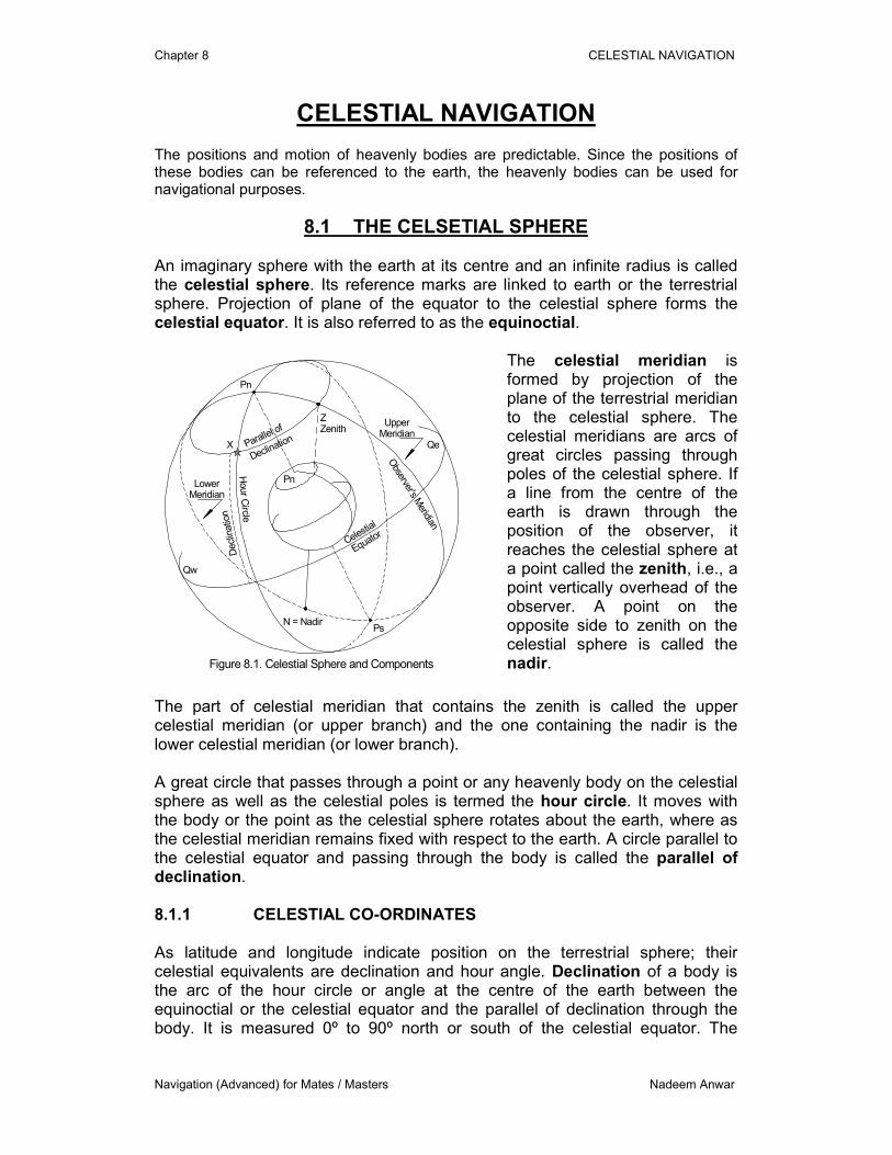
The local hour angle (LHA) is the arc of the equinoctial or the angle at the celestial pole measured westwards between the observers meridian and the hour circle through the body. Due to rotation of the earth on its axis and the revolution around the sun, the hour angle of the bodies changes quite frequently. As there are numerous heavenly bodies, the hour angle data for each would require a huge publication. Two further references are used to minimise hour angle data. For the sun, moon, planets and the First Point of Aries, hourly data is noted with reference to the Greenwich meridian, where as for stars the data is noted with reference to the First Point of Aries every three days. Greenwich hour angle (GHA) of a body is the arc of the equinoctial or the angle at the celestial pole measured westward from the Greenwich meridian to the hour circle through the body. Sidereal hour angle (SHA) of a body is the arc of the equinoctial or the angle at the celestial pole measured westward from the hour circle through First Point of Aries to the hour circle through the body.
G G
Pn Pn
Aries Aries
O O
a
b wc
d
e f
g
a
b e
c
d
e
fg
a = LHA Star
b e = Longitude East
b w = Longitude West
c = GHA Sun
d = GHA Aries
e = SHA Star
f = LHA Sun
g = LHA Aries
Figure 8.2. Longitude, GHA, SHA and LHA
For LHA: Longitude East GHA Least Longitude West GHA Best GHA = 145º 30´ 145º 30´ Longitude = 030º 15´ E 030º 15´ W LHA = 175º 45´ 115º 15º
Example 8.1 (geographical position) Find the geographical position of Venus on 4th May 2006, at 06h 28m 15s GMT.
Chapter 8 CELESTIAL NAVIGATION
Navigation (Advanced) for Mates / Masters Nadeem Anwar
Solution
GMT (Date / Time) 4-5-06 / 06 28 15
Declination 00º 55´.1 S 0600
d Corrn – 0´.5 Decreasing 1.0
Latitude 00º 54´.6 S
GHA 310º 35´.0 0600
Increment 7º 03´.8 28m 15s
v Corrn / SHA - 0´.1 -0.2
Sub total 317º 38´.7
(360º -) - 360º
Longitude 042º 21´.3 E
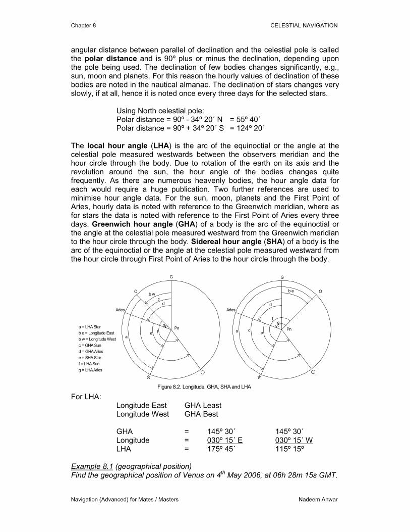
8.2 HORIZONS and ALTITUDES Since the celestial sphere is referred to the centre of the earth, horizon can be used as a reference point for navigational purposes. There are a number of different horizons and all are perpendicular to the line between the zenith and nadir. Visible horizon is the line where the earth and sky appear to meet. It is also referred to as the apparent horizon. It varies with the height of the observer’s eye above the sea and the refraction. Sensible horizon is an imaginary line through the observer’s eye and geoidal horizon is the line tangent to the earth at the observer’s position. Celestial (or rational) horizon is the line through the centre of the earth and is the reference horizon for the celestial calculations. The celestial horizon in the reference system is the primary great circle. There may be other great circles called vertical circles which are perpendicular to the celestial horizon and passing through the zenith and nadir. The arc of vertical circle through the body between the celestial horizon and the zenith is 90º. The arc between the celestial horizon and the body is the true altitude and the arc between the body and the zenith is the zenith distance. Zenith distance of a body is 90º minus the true altitude, where the body is above the celestial horizon. It can be 90º plus the true altitude, where the body is below the celestial horizon.
Z
N
Sensible Horizon
Geoidal Horizon
Geometrical Horizon
Celestial Horizon
Visible Horizon(may not always be the same as geometrical)
Figure 8.3. Horizons
Example 8.2 If the sextant altitude of Jupiter was 35º 37´.4, find the true altitude if the index error of the sextant was 1´.8 off the arc and height of eye was 14.2 m:
Using total correction table A2. Using table A4 if pressure was 1020 mb and temperature was - 4ºC.
Chapter 8 CELESTIAL NAVIGATION
Navigation (Advanced) for Mates / Masters Nadeem Anwar
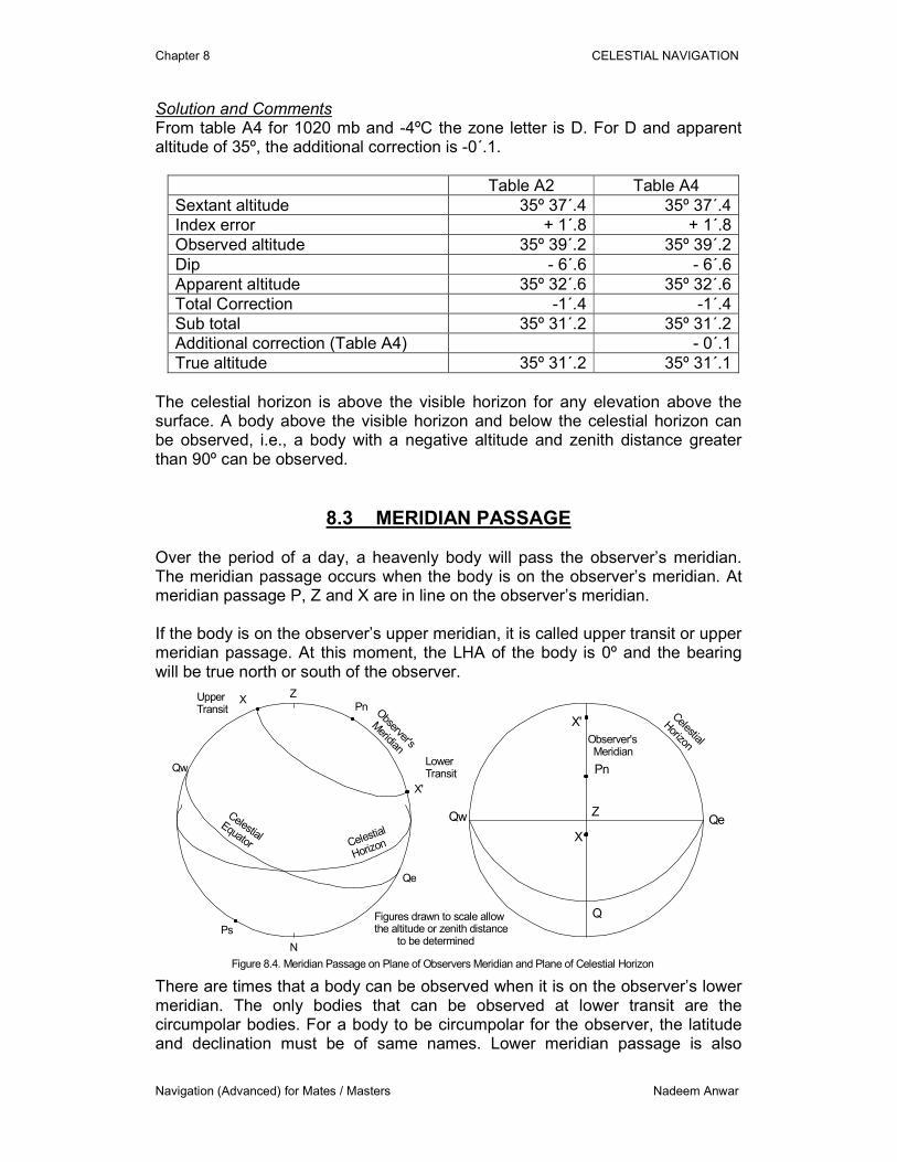
Solution and Comments From table A4 for 1020 mb and -4ºC the zone letter is D. For D and apparent altitude of 35º, the additional correction is -0´.1.
Table A2 Table A4
Sextant altitude 35º 37´.4 35º 37´.4
Index error + 1´.8 + 1´.8
Observed altitude 35º 39´.2 35º 39´.2
Dip - 6´.6 - 6´.6
Apparent altitude 35º 32´.6 35º 32´.6
Total Correction -1´.4 -1´.4
Sub total 35º 31´.2 35º 31´.2
Additional correction (Table A4) - 0´.1
True altitude 35º 31´.2 35º 31´.1
The celestial horizon is above the visible horizon for any elevation above the surface. A body above the visible horizon and below the celestial horizon can be observed, i.e., a body with a negative altitude and zenith distance greater than 90º can be observed.
8.3 MERIDIAN PASSAGE Over the period of a day, a heavenly body will pass the observer’s meridian. The meridian passage occurs when the body is on the observer’s meridian. At meridian passage P, Z and X are in line on the observer’s meridian. If the body is on the observer’s upper meridian, it is called upper transit or upper meridian passage. At this moment, the LHA of the body is 0º and the bearing will be true north or south of the observer.
Z
N
Figure 8.4. Meridian Passage on Plane of Observers Meridian and Plane of Celestial Horizon
Z
Q
X
Pn
PnQw
Qe
Qw Qe
Celestial
Horizon
CelestialEquator
X
X'
UpperTransit
LowerTransit
Ps
X'Celestial
Horizon
Observer's
Meridian
Observer's Meridian
Figures drawn to scale allowthe altitude or zenith distance to be determined
There are times that a body can be observed when it is on the observer’s lower meridian. The only bodies that can be observed at lower transit are the circumpolar bodies. For a body to be circumpolar for the observer, the latitude and declination must be of same names. Lower meridian passage is also
Chapter 8 CELESTIAL NAVIGATION
Navigation (Advanced) for Mates / Masters Nadeem Anwar
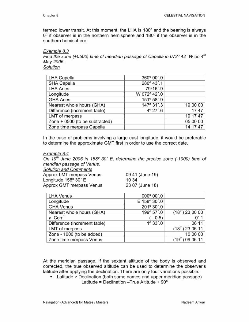
termed lower transit. At this moment, the LHA is 180º and the bearing is always 0º if observer is in the northern hemisphere and 180º if the observer is in the southern hemisphere. Example 8.3 Find the zone (+0500) time of meridian passage of Capella in 072º 42´ W on 4th May 2006. Solution
LHA Capella 360º 00´.0
SHA Capella 280º 43´.1
LHA Aries 79º16´.9
Longitude W 072º 42´.0
GHA Aries 151º 58´.9
Nearest whole hours (GHA) 147º 31´.3 19 00 00
Difference (increment table) 4º 27´.6 17 47
LMT of merpass 19 17 47
Zone + 0500 (to be subtracted) 05 00 00
Zone time merpass Capella 14 17 47
In the case of problems involving a large east longitude, it would be preferable to determine the approximate GMT first in order to use the correct date. Example 8.4 On 19th June 2006 in 158º 30´ E, determine the precise zone (-1000) time of meridian passage of Venus. Solution and Comments Approx LMT merpass Venus 09 41 (June 19) Longitude 158º 30´ E 10 34 Approx GMT merpass Venus 23 07 (June 18)
LHA Venus 000º 00´.0
Longitude E 158º 30´.0
GHA Venus 201º 30´.0
Nearest whole hours (GHA) 199º 57´.0 (18th) 23 00 00
v Corrn ( - 0.5) 0´.1
Difference (increment table) 1º 33´.0 06 11
LMT of merpass (18th) 23 06 11
Zone - 1000 (to be added) 10 00 00
Zone time merpass Venus (19th) 09 06 11
At the meridian passage, if the sextant altitude of the body is observed and corrected, the true observed altitude can be used to determine the observer’s latitude after applying the declination. There are only four variations possible:
� Latitude > Declination (both same names and upper meridian passage) Latitude = Declination –True Altitude + 90º
Chapter 8 CELESTIAL NAVIGATION
Navigation (Advanced) for Mates / Masters Nadeem Anwar
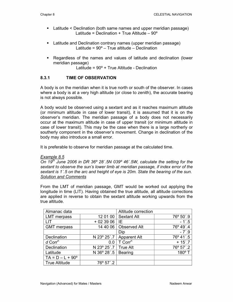
� Latitude < Declination (both same names and upper meridian passage) Latitude = Declination + True Altitude – 90º
� Latitude and Declination contrary names (upper meridian passage)
Latitude = 90º – True altitude – Declination
� Regardless of the names and values of latitude and declination (lower meridian passage)
Latitude = 90º + True Altitude - Declination 8.3.1 TIME OF OBSERVATION A body is on the meridian when it is true north or south of the observer. In cases where a body is at a very high altitude (or close to zenith), the accurate bearing is not always possible. A body would be observed using a sextant and as it reaches maximum altitude (or minimum altitude in case of lower transit), it is assumed that it is on the observer’s meridian. The meridian passage of a body does not necessarily occur at the maximum altitude in case of upper transit (or minimum altitude in case of lower transit). This may be the case when there is a large northerly or southerly component in the observer’s movement. Change in declination of the body may also introduce a small error. It is preferable to observe for meridian passage at the calculated time. Example 8.5 On 19th June 2006 in DR 36º 28´.5N 039º 46´.5W, calculate the setting for the sextant to observe the sun’s lower limb at meridian passage, if index error of the sextant is 1´.5 on the arc and height of eye is 20m. State the bearing of the sun. Solution and Comments From the LMT of meridian passage, GMT would be worked out applying the longitude in time (LIT). Having obtained the true altitude, all altitude corrections are applied in reverse to obtain the sextant altitude working upwards from the true altitude.
Almanac data Altitude correction
LMT merpass 12 01 00 Sextant Alt 76º 50´.9
LIT + 02 39 06 IE - 1´.5
GMT merpass 14 40 06 Observed Alt 76º 49´.4
Dip - 7´.9
Declination N 23º 25´.7 Apparent Alt 76º 41´.5
d Corrn 0.0 T Corrn + 15´.7
Declination N 23º 25´.7 True Alt 76º 57´.2
Latitude N 36º 28´.5 Bearing 180º T
TA = D – L + 90º
True Altitude 76º 57´.2
Chapter 8 CELESTIAL NAVIGATION
Navigation (Advanced) for Mates / Masters Nadeem Anwar
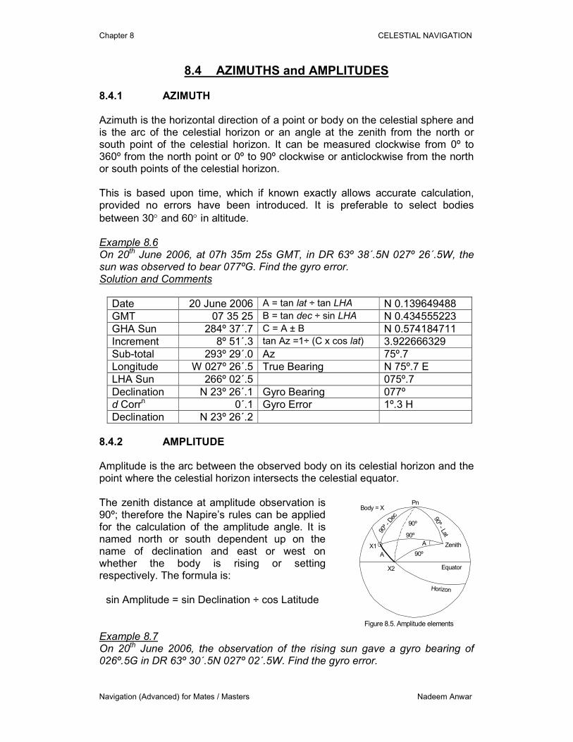
8.4 AZIMUTHS and AMPLITUDES 8.4.1 AZIMUTH Azimuth is the horizontal direction of a point or body on the celestial sphere and is the arc of the celestial horizon or an angle at the zenith from the north or south point of the celestial horizon. It can be measured clockwise from 0º to 360º from the north point or 0º to 90º clockwise or anticlockwise from the north or south points of the celestial horizon. This is based upon time, which if known exactly allows accurate calculation, provided no errors have been introduced. It is preferable to select bodies
between 30° and 60° in altitude. Example 8.6 On 20th June 2006, at 07h 35m 25s GMT, in DR 63º 38´.5N 027º 26´.5W, the sun was observed to bear 077ºG. Find the gyro error. Solution and Comments
Date 20 June 2006 A = tan lat ÷ tan LHA N 0.139649488
GMT 07 35 25 B = tan dec ÷ sin LHA N 0.434555223
GHA Sun 284º 37´.7 C = A ± B N 0.574184711
Increment 8º 51´.3 tan Az =1÷ (C x cos lat) 3.922666329
Sub-total 293º 29´.0 Az 75º.7
Longitude W 027º 26´.5 True Bearing N 75º.7 E
LHA Sun 266º 02´.5 075º.7
Declination N 23º 26´.1 Gyro Bearing 077º
d Corrn 0´.1 Gyro Error 1º.3 H
Declination N 23º 26´.2
8.4.2 AMPLITUDE Amplitude is the arc between the observed body on its celestial horizon and the point where the celestial horizon intersects the celestial equator. The zenith distance at amplitude observation is 90º; therefore the Napire’s rules can be applied for the calculation of the amplitude angle. It is named north or south dependent up on the name of declination and east or west on whether the body is rising or setting respectively. The formula is:
sin Amplitude = sin Declination ÷ cos Latitude
A
Pn
Horizon
90º -
Dec 90º - Lat
Zenith
Body = X
A
90º
90º
Equator
90º
X1
X2
Figure 8.5. Amplitude elements Example 8.7 On 20th June 2006, the observation of the rising sun gave a gyro bearing of 026º.5G in DR 63º 30´.5N 027º 02´.5W. Find the gyro error.
Chapter 8 CELESTIAL NAVIGATION
Navigation (Advanced) for Mates / Masters Nadeem Anwar
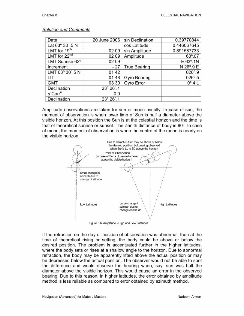
Solution and Comments
Date 20 June 2006 sin Declination 0.39770844
Lat 63º 30´.5 N cos Latitude 0.446067645
LMT for 19th 02 09 sin Amplitude 0.891587733
LMT for 22nd 02 09 Amplitude 63º.07
LMT Sunrise 62º 02 09 E 63º.1N
Increment - 27 True Bearing N 26º.9 E
LMT 63º 30´.5 N 01 42 026º.9
LIT 01 48 Gyro Bearing 026º.5
GMT 03 30 Gyro Error 0º.4 L
Declination 23º 26´.1
d Corrn 0.0
Declination 23º 26´.1
Amplitude observations are taken for sun or moon usually. In case of sun, the moment of observation is when lower limb of Sun is half a diameter above the visible horizon. At this position the Sun is at the celestial horizon and the time is
that of theoretical sunrise or sunset. The Zenith distance of body is 90°. In case of moon, the moment of observation is when the centre of the moon is nearly on the visible horizon.
High LatitudesLow Latitudes
Small change inazimuth due tochange of altitude
Large change inazimuth due tochange of altitude
Point of Observation(In case of Sun - LL semi-diameter above the visible horizon)
Due to refraction Sun may be above or below the desired position, but bearing observed when Sun's LL is SD above the horizon
Figure 8.6. Amplitude - High and Low Latitudes
If the refraction on the day or position of observation was abnormal, then at the time of theoretical rising or setting, the body could be above or below the desired position. The problem is accentuated further in the higher latitudes, where the body sets or rises at a shallow angle to the horizon. Due to abnormal refraction, the body may be apparently lifted above the actual position or may be depressed below the actual position. The observer would not be able to spot the difference and would observe the bearing when, say, sun was half the diameter above the visible horizon. This would cause an error in the observed bearing. Due to this reason, in higher latitudes, the error obtained by amplitude method is less reliable as compared to error obtained by azimuth method.
Chapter 8 CELESTIAL NAVIGATION
Navigation (Advanced) for Mates / Masters Nadeem Anwar
If the Examples 8.6 and 8.7 relate to the same ship and as the gyro error was obtained on the same day, at this high latitude the results of azimuth observation would be more reliable as compared to the amplitude observation.
8.5 ASTRONOMICAL POSITION LINES 8.5.1 NAVIGATIONAL TRIANGLE
Pn
Ps
X
Z = Zenith
N = Nadir
Qw
Qe
AP
GPPn
Celestial
Equator
CelestialHorizon
Obs
erve
r's
Mer
idia
n
Declination
Alti
tude
Azimuth
LHA
Figure 8.7. PZX Triangle on Plane of Observer'sMeridian with corresponding Assumed Position and Geographical Position on the Earth
HourCircle
Vertical Circle
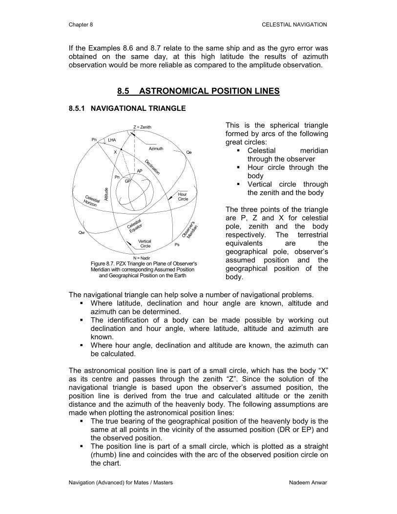
This is the spherical triangle formed by arcs of the following great circles:
� Celestial meridian through the observer
� Hour circle through the body
� Vertical circle through the zenith and the body
The three points of the triangle are P, Z and X for celestial pole, zenith and the body respectively. The terrestrial equivalents are the geographical pole, observer’s assumed position and the geographical position of the body.
The navigational triangle can help solve a number of navigational problems.
� Where latitude, declination and hour angle are known, altitude and azimuth can be determined.
� The identification of a body can be made possible by working out declination and hour angle, where latitude, altitude and azimuth are known.
� Where hour angle, declination and altitude are known, the azimuth can be calculated.
The astronomical position line is part of a small circle, which has the body “X” as its centre and passes through the zenith “Z”. Since the solution of the navigational triangle is based upon the observer’s assumed position, the position line is derived from the true and calculated altitude or the zenith distance and the azimuth of the heavenly body. The following assumptions are made when plotting the astronomical position lines:
� The true bearing of the geographical position of the heavenly body is the same at all points in the vicinity of the assumed position (DR or EP) and the observed position.
� The position line is part of a small circle, which is plotted as a straight (rhumb) line and coincides with the arc of the observed position circle on the chart.
Chapter 8 CELESTIAL NAVIGATION
Navigation (Advanced) for Mates / Masters Nadeem Anwar
� The direction of the intercept is part of a great circle forming the true bearing to or from the body and is plotted as a straight (rhumb) line.
� When a number of position lines are to be plotted for a common time of position, these position lines are run onwards or backwards.
There are a few methods of determining the position lines. Examples for only two are provided below. 8.5.1 INTERCEPT METHOD (Marq St Hilaire) In this method, the calculated zenith distance and azimuth are worked out from the observer’s DR (assumed position). The calculated zenith distance (CZD) is compared with true zenith distance (TZD) to determine the intercept. The position line is plotted perpendicular to the azimuth, from the intercept terminal point. The intercept is plotted towards or away depending whether the TZD is less than or more than the CZD respectively. TZD less than CZD: Intercept Towards TZD more than CZD: Intercept Away True Altitude less than Calculated Altitude: Intercept Away True Altitude more than Calculated Altitude: Intercept Towards Cosine method can be used for the zenith distance:
cos ZX = cos PZ cos PX + sin PZ sin PX cos ZPX or
cos ZX = sin Lat sin Dec +/- cos Lat cos Dec cos LHA 8.5.2 LONGITUDE BY CHRONOMETRE This method provides a calculated longitude through the DR latitude for plotting the position line. The plotting is simplified as no intercept is involved. The method is not suitable for a body approaching the meridian as a large displacement of longitude may be generated due to small errors. The calculation involves working out the LHA which provides the calculated longitude:
LHA – GHA = East Longitude GHA – LHA = West Longitude cos LHA = sin True Altitude – (sin Dec sin Lat)
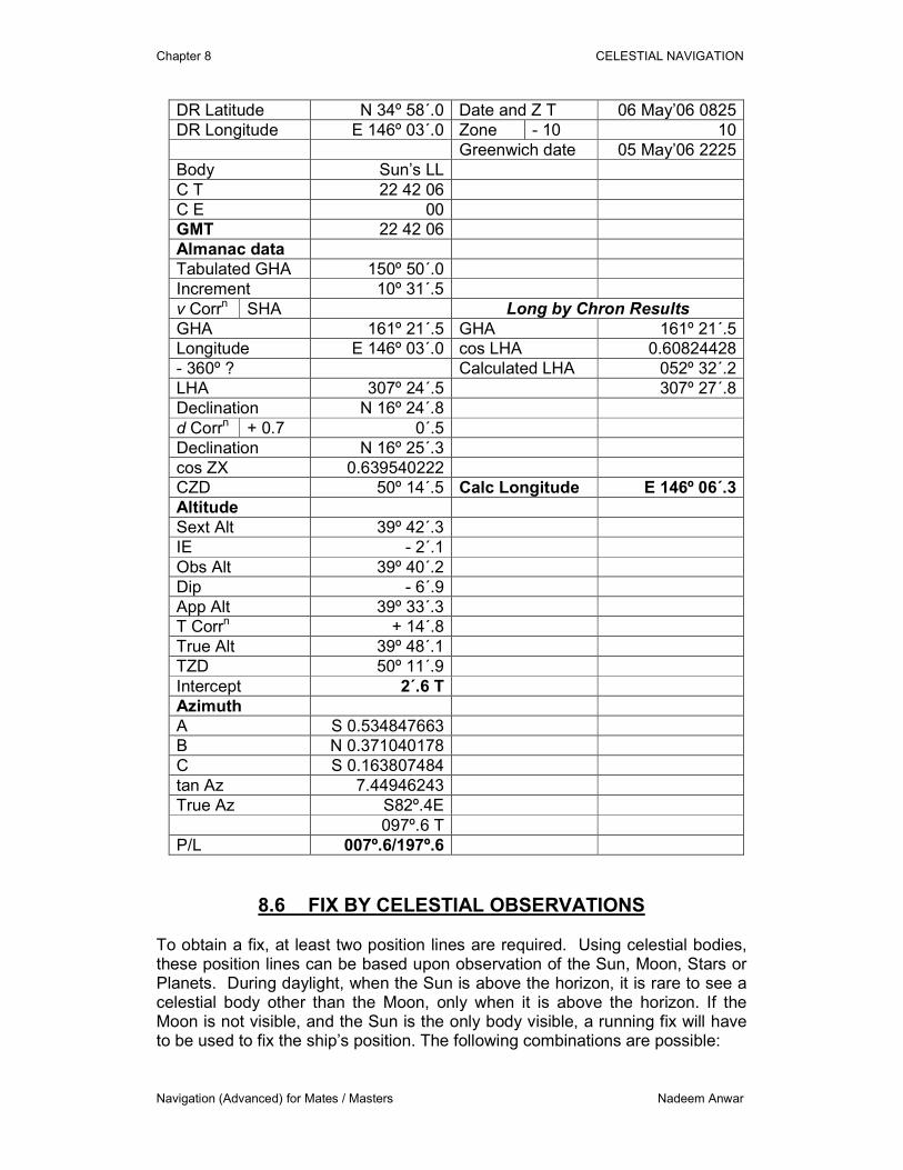
cos Dec cos Lat Calculations involving long by chron have been added to Example 8.8 solution. Example 8.8 At 0825 on 06th May 2006, in DR 34º 58´.0 N 146º 03´.0 E, the sextant altitude of the Sun’s lower limb was 39º 42´.3 when the chronometer showed 10h 42m 06s. The chronometer has no error. Find the intercept and direction of position line if the index error is 2´.1 on the arc and the height of eye is 15.4m. Solution and Comments
Chapter 8 CELESTIAL NAVIGATION
Navigation (Advanced) for Mates / Masters Nadeem Anwar
DR Latitude N 34º 58´.0 Date and Z T 06 May’06 0825
DR Longitude E 146º 03´.0 Zone - 10 10
Greenwich date 05 May’06 2225
Body Sun’s LL
C T 22 42 06
C E 00
GMT 22 42 06
Almanac data
Tabulated GHA 150º 50´.0
Increment 10º 31´.5
v Corrn SHA Long by Chron Results
GHA 161º 21´.5 GHA 161º 21´.5
Longitude E 146º 03´.0 cos LHA 0.60824428
- 360º ? Calculated LHA 052º 32´.2
LHA 307º 24´.5 307º 27´.8
Declination N 16º 24´.8
d Corrn + 0.7 0´.5
Declination N 16º 25´.3
cos ZX 0.639540222
CZD 50º 14´.5 Calc Longitude E 146º 06´.3
Altitude
Sext Alt 39º 42´.3
IE - 2´.1
Obs Alt 39º 40´.2
Dip - 6´.9
App Alt 39º 33´.3
T Corrn + 14´.8
True Alt 39º 48´.1
TZD 50º 11´.9
Intercept 2´.6 T
Azimuth
A S 0.534847663
B N 0.371040178
C S 0.163807484
tan Az 7.44946243
True Az S82º.4E
097º.6 T
P/L 007º.6/197º.6
8.6 FIX BY CELESTIAL OBSERVATIONS To obtain a fix, at least two position lines are required. Using celestial bodies, these position lines can be based upon observation of the Sun, Moon, Stars or Planets. During daylight, when the Sun is above the horizon, it is rare to see a celestial body other than the Moon, only when it is above the horizon. If the Moon is not visible, and the Sun is the only body visible, a running fix will have to be used to fix the ship’s position. The following combinations are possible:
Chapter 8 CELESTIAL NAVIGATION
Navigation (Advanced) for Mates / Masters Nadeem Anwar
Sun – run – Sun Sun – run – Meridian Altitude of Sun Meridian Altitude of Sun – run – Sun Sun – run – Moon or Moon – run – Sun Sun – run – Star/Planet Star/Planet – run – Sun (stars/planets during twilight only)
At night the horizon is not distinct to obtain the altitudes required for working out sights – the only exception being within three days of Full Moon, when the horizon can be clear for taking altitudes. As during the day, stars and planets are not visible and at night the horizon is not visible, sights of stars and planets can only be take when both are distinct, i.e., during twilight. The twilights are categorised as (when sun is):
Civil : Sunset to 6º below the horizon Nautical : Sun 6º to 12º below the horizon Astronomical : Sun 12º to 18º below the horizon
Total darkness occurs when the sun is 18º or more below the horizon. The best time for observation is the beginning of nautical twilight in the evening and end of nautical twilight in the morning. Since a number of bodies may have to be observed, a time window should be allowed when sun is between 3º and 9º below the horizon, i.e., half way between period of civil twilight to or from half way between periods of nautical twilight. Just like the circumpolar concept, twilight may also last all night, allowing sights to be observed more frequently. 8.6.1 PLANNING SIGHTS 8.6.1.1 SELECTION OF HEAVENLY BODIES For a fix to be reliable, the selection of stars and planets needs some consideration. The following points should be considered when planning a morning or an evening sight:
� Using a star chart or globe, the stars and planets to be used should be determined.
� 3 or more stars and/or planets should be selected. Select 4 standby stars in addition, in case of partly cloudy sky.
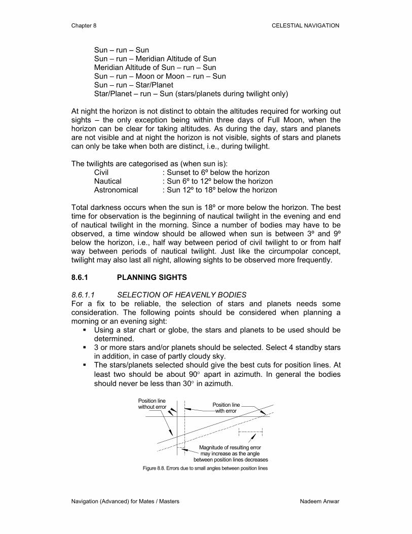
� The stars/planets selected should give the best cuts for position lines. At
least two should be about 90° apart in azimuth. In general the bodies
should never be less than 30° in azimuth.
Position linewithout error Position line
with error
Magnitude of resulting error may increase as the anglebetween position lines decreases
Figure 8.8. Errors due to small angles between position lines
Chapter 8 CELESTIAL NAVIGATION
Navigation (Advanced) for Mates / Masters Nadeem Anwar
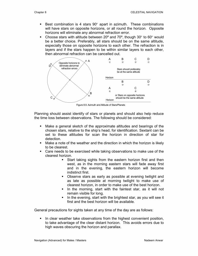
� Best combination is 4 stars 90° apart in azimuth. These combinations will have stars on opposite horizons, or all round the horizon. Opposite horizons will eliminate any abnormal refraction error.
� Choose stars with altitude between 20º and 70º, though 30° to 60° would be a better choice. Preferably, all stars should be on the same altitude, especially those on opposite horizons to each other. The refraction is in layers and if the stars happen to be within similar layers to each other, then abnormal refraction can be cancelled out.
Opposite horizons to eliminate abnormal refraction errors
A
B
C
D
Stars should preferablybe at the same altitude
or Stars on opposite horizons should be the same altitude
A B C D
A
B
C
D
Figure 8.9. Azimuth and Altitude of Stars/Planets
Horizon
Horizon
Planning should assist identify of stars or planets and should also help reduce the time loss between observations. The following should be considered:
� Make a general sketch of the approximate altitudes and bearings of the chosen stars, relative to the ship’s head, for identification. Sextant can be set to these altitudes for scan the horizon in direction of star for detection.
� Make a note of the weather and the direction in which the horizon is likely to be clearest.
� Care needs to be exercised while taking observations to make use of the clearest horizon.
� Start taking sights from the eastern horizon first and then west, as in the morning eastern stars will fade away first and in the evening, the eastern horizon will become indistinct first.
� Observe stars as early as possible at evening twilight and as late as possible at morning twilight to make use of clearest horizon, in order to make use of the best horizon.
� In the morning, start with the faintest star, as it will not remain visible for long.
� In the evening, start with the brightest star, as you will see it first and the best horizon will be available.
General precautions for sights taken at any time of the day are as follows:
� In clear weather take observations from the highest convenient position, to take advantage of the clear distant horizon. This avoids errors due to high waves obscuring the horizon and parallax.

Chapter 8 CELESTIAL NAVIGATION
Navigation (Advanced) for Mates / Masters Nadeem Anwar
� Always swing the sextant a few degrees each side of vertical plane, as the body is brought to the horizon. Adjustments to the altitude should then be made by micrometer, until it just touches the horizon.
� When possible, check the sextant for side error before taking sights. � When possible, take the index error before and after sights. � When observing the Sun, use sufficiently strong shades to avoid any
possibility of dazzle. � If the identity of a body is uncertain after taking altitude, take its bearing. � When the ship is rolling heavily, observations should be taken from close
to the centre line of the vessel to minimise errors due to changing DIP.
In hazy conditions sightfrom lowest level reducesthe distance to geometric horizon allowing use of clearer horizon
In clear visibility sight fromhighest level increases the distance to geometric horizon allowing use of clearest horizon
Figure 8.10. Observation points on ship in different conditions 8.6.2 SIGHTS IN HAZY CONDITIONS
� In haze or mist, take observations from the lowest convenient position, as the nearer horizon is likely to be clearer.
� With an indistinct, cloudy or hazy sun, align the middle of the disk with the horizon instead of UL or LL. (Altitude corrections, less than for SD, must be applied separately).
� When possible, take observations of a heavenly body in sets of three or five at approximately equal time intervals.
� When the horizon is poor, it is essential to take several altitudes of each body and to set the sextant to a given increase or decrease or increase between each observation. If time intervals are not equal, sights should be either discarded or used with extreme caution.
8.6.3 ABNORMAL REFRACTION
� Opposite horizons: A pair of stars on opposite sides of horizon (almost 180º apart in azimuth) should be observed to cancel out the effect of refraction. When the two position lines are plotted, the linear or angular distance between them should be halved. A second pair 90º different in azimuth from the first pair should be observed and plotted in the same manner as the first pair (Example 8. illustrates this point).
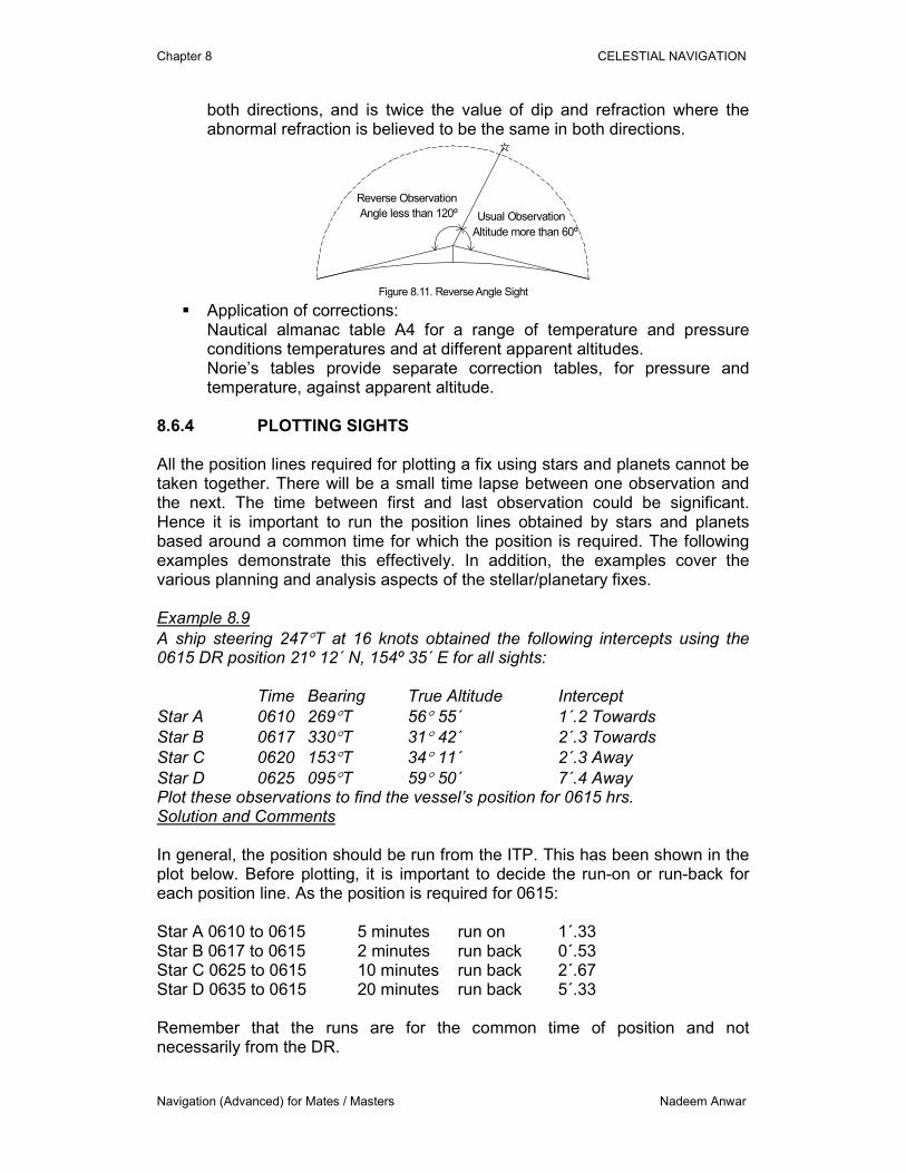
� Reverse angle sight: A body at an altitude higher than 60º should be observed twice – once the normal observation of least altitude and once the reverse observation (180º - least altitude) on the opposite horizon. (NB: Sextant can only measure angles up to 120º. 180º - >60º = <120º). The two altitudes (corrected for index error) should be added and their sum subtracted from 180º. The resulting difference is the sum of dip and refraction in
Chapter 8 CELESTIAL NAVIGATION
Navigation (Advanced) for Mates / Masters Nadeem Anwar
both directions, and is twice the value of dip and refraction where the abnormal refraction is believed to be the same in both directions.
Usual Observation
Reverse Observation
Angle less than 120º
Altitude more than 60º
Figure 8.11. Reverse Angle Sight � Application of corrections:
Nautical almanac table A4 for a range of temperature and pressure conditions temperatures and at different apparent altitudes. Norie’s tables provide separate correction tables, for pressure and temperature, against apparent altitude.
8.6.4 PLOTTING SIGHTS All the position lines required for plotting a fix using stars and planets cannot be taken together. There will be a small time lapse between one observation and the next. The time between first and last observation could be significant. Hence it is important to run the position lines obtained by stars and planets based around a common time for which the position is required. The following examples demonstrate this effectively. In addition, the examples cover the various planning and analysis aspects of the stellar/planetary fixes. Example 8.9
A ship steering 247°T at 16 knots obtained the following intercepts using the 0615 DR position 21º 12´ N, 154º 35´ E for all sights: Time Bearing True Altitude Intercept
Star A 0610 269°T 56° 55´ 1´.2 Towards
Star B 0617 330°T 31° 42´ 2´.3 Towards
Star C 0620 153°T 34° 11´ 2´.3 Away
Star D 0625 095°T 59° 50´ 7´.4 Away Plot these observations to find the vessel’s position for 0615 hrs. Solution and Comments In general, the position should be run from the ITP. This has been shown in the plot below. Before plotting, it is important to decide the run-on or run-back for each position line. As the position is required for 0615: Star A 0610 to 0615 5 minutes run on 1´.33 Star B 0617 to 0615 2 minutes run back 0´.53 Star C 0625 to 0615 10 minutes run back 2´.67 Star D 0635 to 0615 20 minutes run back 5´.33 Remember that the runs are for the common time of position and not necessarily from the DR.
Chapter 8 CELESTIAL NAVIGATION
Navigation (Advanced) for Mates / Masters Nadeem Anwar
DR 0615
All stars plotted from
A
B
C
D
Scale = nm
1.00.5North
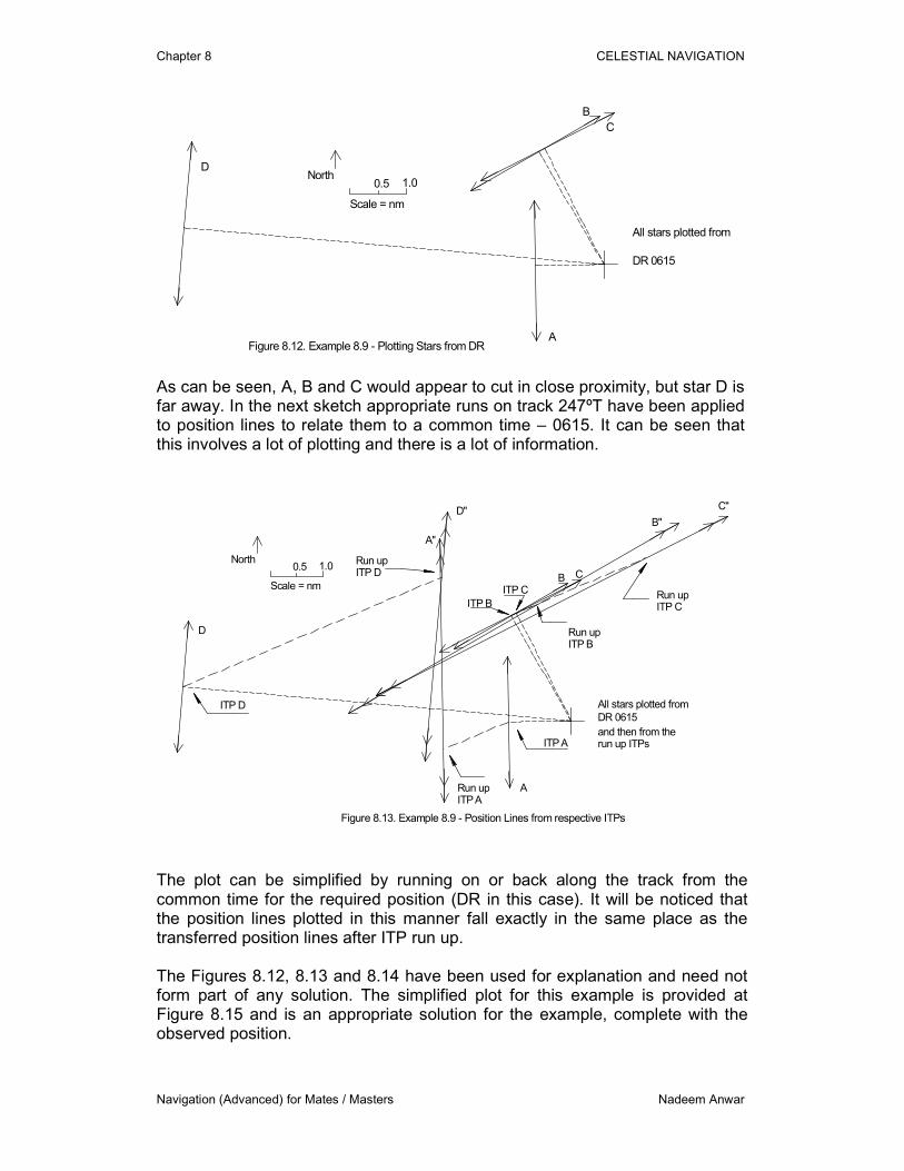
Figure 8.12. Example 8.9 - Plotting Stars from DR As can be seen, A, B and C would appear to cut in close proximity, but star D is far away. In the next sketch appropriate runs on track 247ºT have been applied to position lines to relate them to a common time – 0615. It can be seen that this involves a lot of plotting and there is a lot of information.
DR 0615
All stars plotted from
A
B C
D
North
ITP A
ITP B
ITP C
ITP D
Run upITP A
Run upITP B
Run upITP C
Run upITP D
Scale = nm
1.00.5
C"
B"D"
A"
and then from therun up ITPs
Figure 8.13. Example 8.9 - Position Lines from respective ITPs
The plot can be simplified by running on or back along the track from the common time for the required position (DR in this case). It will be noticed that the position lines plotted in this manner fall exactly in the same place as the transferred position lines after ITP run up. The Figures 8.12, 8.13 and 8.14 have been used for explanation and need not form part of any solution. The simplified plot for this example is provided at Figure 8.15 and is an appropriate solution for the example, complete with the observed position.
Chapter 8 CELESTIAL NAVIGATION
Navigation (Advanced) for Mates / Masters Nadeem Anwar
Run upITP A
Run upITP C
Run upITP B
Run upITP D
ITP D
DR 0615
All original position lines left in place as plotted from DR. Transferred position lineslinked to run on and run back along the track
A
B C
D
North
ITP B
ITP CScale = nm
1.00.5
C"
B"
D"
A"
ITP A
Run on A
Run back B
Run back C
Run back D
247º T @ 16 kts
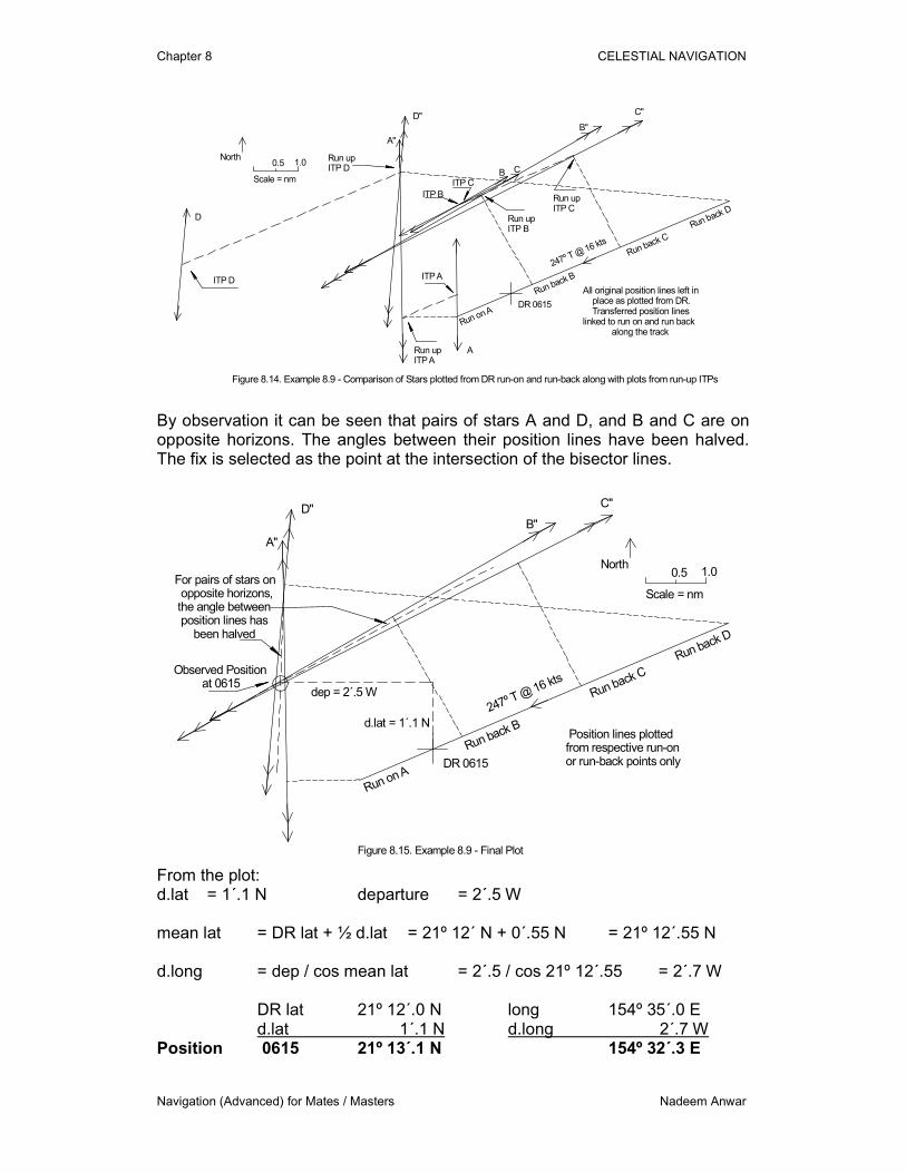
Figure 8.14. Example 8.9 - Comparison of Stars plotted from DR run-on and run-back along with plots from run-up ITPs
By observation it can be seen that pairs of stars A and D, and B and C are on opposite horizons. The angles between their position lines have been halved. The fix is selected as the point at the intersection of the bisector lines.
DR 0615
Position lines plottedfrom respective run-onor run-back points only
North
Scale = nm
1.00.5
C"
B"
D"
A"
Run on A
Run back B
Run back C
Run back D
247º T @ 16 kts
For pairs of stars on opposite horizons, the angle between position lines has been halved
Observed Position at 0615
dep = 2´.5 W
d.lat = 1´.1 N
Figure 8.15. Example 8.9 - Final Plot
From the plot: d.lat = 1´.1 N departure = 2´.5 W mean lat = DR lat + ½ d.lat = 21º 12´ N + 0´.55 N = 21º 12´.55 N d.long = dep / cos mean lat = 2´.5 / cos 21º 12´.55 = 2´.7 W
DR lat 21º 12´.0 N long 154º 35´.0 E d.lat 1´.1 N d.long 2´.7 W
Position 0615 21º 13´.1 N 154º 32´.3 E
Chapter 8 CELESTIAL NAVIGATION
Navigation (Advanced) for Mates / Masters Nadeem Anwar
Reliability of Position In case it was required to comment on the reliability of an observed position, the following should be argued:
� Number of stars � Azimuth between stars, 90º, but not less than 30º � Opposite horizons � Altitude between 20º and 70º � Altitude of stars same or at least same for opposite horizon stars � Resultant angle of cut between bisector lines
Example 8.10
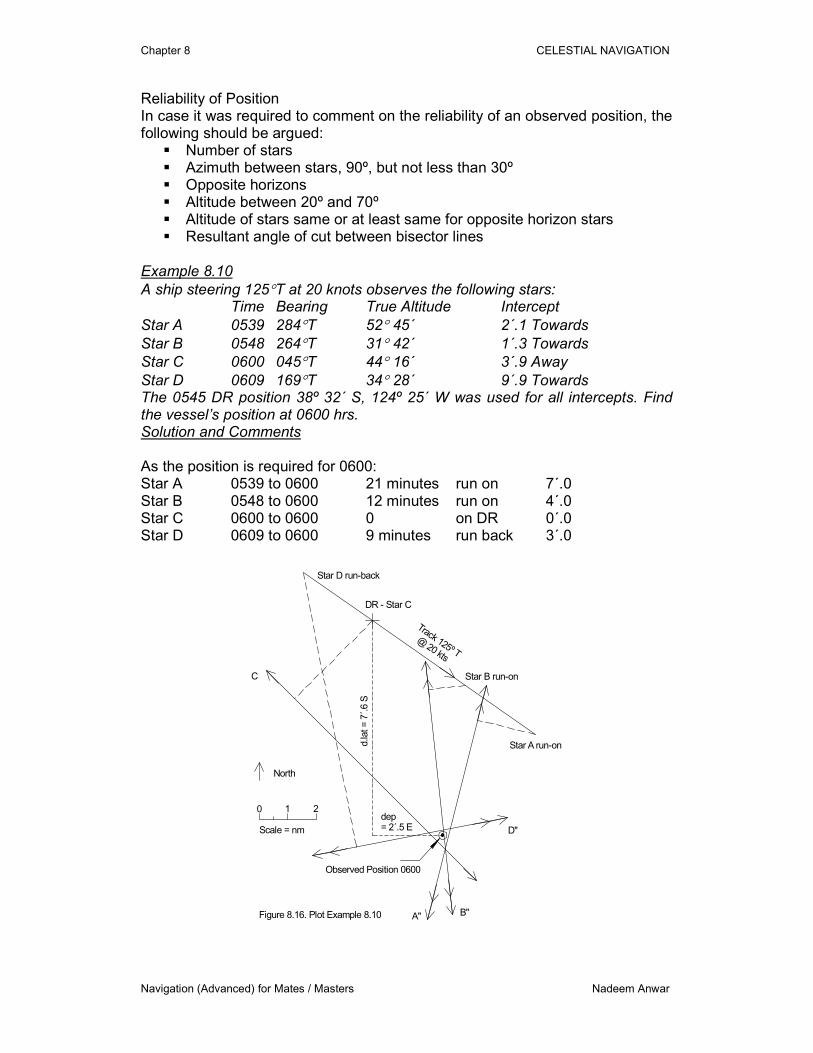
A ship steering 125°T at 20 knots observes the following stars: Time Bearing True Altitude Intercept
Star A 0539 284°T 52° 45´ 2´.1 Towards
Star B 0548 264°T 31° 42´ 1´.3 Towards
Star C 0600 045°T 44° 16´ 3´.9 Away
Star D 0609 169°T 34° 28´ 9´.9 Towards The 0545 DR position 38º 32´ S, 124º 25´ W was used for all intercepts. Find the vessel’s position at 0600 hrs. Solution and Comments As the position is required for 0600: Star A 0539 to 0600 21 minutes run on 7´.0 Star B 0548 to 0600 12 minutes run on 4´.0 Star C 0600 to 0600 0 on DR 0´.0 Star D 0609 to 0600 9 minutes run back 3´.0
Figure 8.16. Plot Example 8.10
DR - Star C
Star B run-on
Star A run-on
Star D run-back
C
D"
B"A"
d.la
t = 7
´.6 S
dep= 2´.5 E
Observed Position 0600
North
0 1 2
Scale = nm
Track 125º T
@ 20 kts
Chapter 8 CELESTIAL NAVIGATION
Navigation (Advanced) for Mates / Masters Nadeem Anwar
At first glance (having worked Example 8.9), it may appear to an inexperienced navigator that stars A and B are on opposite horizon. This may lead to a serious error as the navigator may simply halve the angle between these two stars. For opposite horizons, it is the azimuth that needs to be considered and not the angle between position lines. In this case, stars B and D are almost at right angle and the stars A and C have an angle of 65º and 56º with star D respectively. Similarly stars A and C have an angle of 59º between them. The position has been plotted close to the intersection of B and D with allowance made for A and C. The actual intersection between position lines of A, B and C is not the observed position. Remember that a position line should not be discarded as it is away from an intersection. In this case position line D has the best angles of cut with all other position lines. From the plot: d.lat = 7´.6 S departure = 2´.5 E mean lat = DR lat + ½ d.lat = 38º 32´ S + 3´.8 S = 38º 35´.8 S d.long = dep / cos mean lat = 2´.5 / cos 38º 35´.8 = 3´.2 W
DR lat 38º 32´.0 S long 124º 25´.0 W d.lat 7´.6 S d.long 3´.2 W
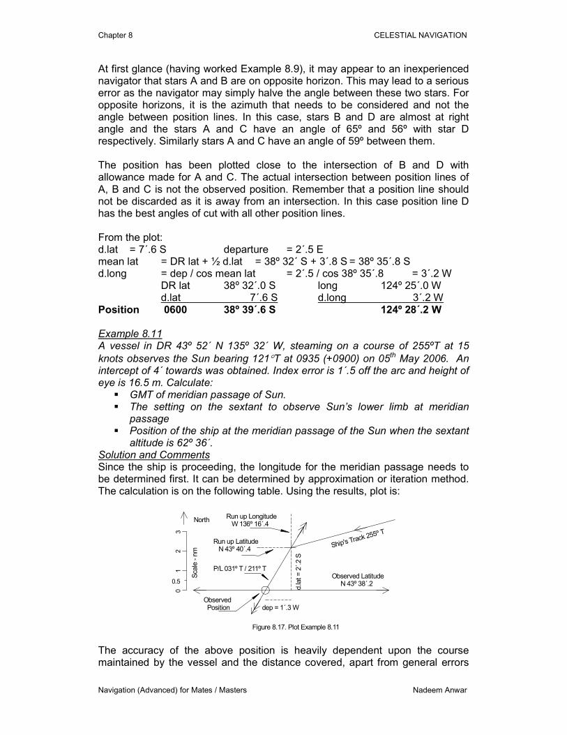
Position 0600 38º 39´.6 S 124º 28´.2 W Example 8.11 A vessel in DR 43º 52´ N 135º 32´ W, steaming on a course of 255ºT at 15
knots observes the Sun bearing 121°T at 0935 (+0900) on 05th May 2006. An intercept of 4´ towards was obtained. Index error is 1´.5 off the arc and height of eye is 16.5 m. Calculate:
� GMT of meridian passage of Sun. � The setting on the sextant to observe Sun’s lower limb at meridian
passage � Position of the ship at the meridian passage of the Sun when the sextant
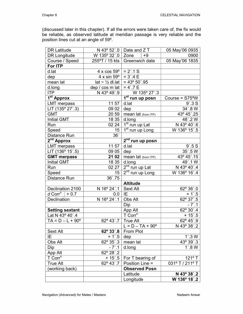
altitude is 62º 36´. Solution and Comments Since the ship is proceeding, the longitude for the meridian passage needs to be determined first. It can be determined by approximation or iteration method. The calculation is on the following table. Using the results, plot is:
Observed Latitude N 43º 38´.2
Run up Latitude N 43º 40´.4
Run up Longitude W 136º 16´.4
Ship's Track 255º T
P/L 031º T / 211º T
d.la
t = 2
´.2 S
dep = 1´.3 WObserved Position
Figure 8.17. Plot Example 8.11
0.5
01
23
North
Sca
le -
nm
The accuracy of the above position is heavily dependent upon the course maintained by the vessel and the distance covered, apart from general errors
Chapter 8 CELESTIAL NAVIGATION
Navigation (Advanced) for Mates / Masters Nadeem Anwar
(discussed later in this chapter). If all the errors were taken care of, the fix would be reliable, as observed latitude at meridian passage is very reliable and the position lines cut at an angle of 59º.
DR Latitude N 43º 52´.0 Date and Z T 05 May’06 0935
DR Longitude W 135º 32´.0 Zone +9 0900
Course / Speed 255ºT / 15 kts Greenwich date 05 May’06 1835
For ITP
d.lat 4 x cos 59º = 2´.1 S
dep 4 x sin 59º = 3´.4 E
mean lat lat ~ ½ dl.lat = 43º 50´.95
d.long dep / cos m lat = 4´.7 E
ITP N 43º 49´.9 W 135º 27´.3
1st Approx 1st run up posn Course = S75ºW
LMT merpass 11 57 d.lat 9´.3 S
LIT (135º 27´.3) 09 02 dep 34´.8 W
GMT 20 59 mean lat (from ITP) 43º 45´.25
Initial GMT 18 35 d.long 48´.2 W
Run 02 24 1st run up Lat N 43º 40´.6
Speed 15 1st run up Long W 136º 15´.5
Distance Run 36´
2nd Approx 2nd run up posn
LMT merpass 11 57 d.lat 9´.5 S
LIT (136º 15´.5) 09 05 dep 35´.5 W
GMT merpass 21 02 mean lat (from ITP) 43º 45´.15
Initial GMT 18 35 d.long 49´.1 W
Run 02 27 2nd run up Lat N 43º 40´.4
Speed 15 2nd run up Long W 136º 16´.4
Distance Run 36´.75
Altitude
Declination 2100 N 16º 24´.1 Sext Alt 62º 36´.0
d Corrn + 0.7 0.0 IE + 1´.5
Declination N 16º 24´.1 Obs Alt 62º 37´.5
Dip - 7´.1
Setting sextant App Alt 62º 30´.4
Lat N 43º 40´.4 T Corrn + 15´.5
TA = D – L + 90º 62º 43´.7 True Alt 62º 45´.9
L = D – TA + 90º N 43º 38´.2
Sext Alt 62º 33´.8 From Plot
IE + 1´.5 dep 1´.3 W
Obs Alt 62º 35´.3 mean lat 43º 39´.3
Dip - 7´.1 d.long 1´.8 W
App Alt 62º 28´.2
T Corrn + 15´.5 For T bearing of 121º T
True Alt 62º 43´.7 Position Line = 031º T / 211º T
(working back) Observed Posn
Latitude N 43º 38´.2
Longitude W 136º 18´.2
Chapter 8 CELESTIAL NAVIGATION
Navigation (Advanced) for Mates / Masters Nadeem Anwar
8.6.5 ERRORS IN ASTRONOMICAL POSITION LINES
� The position lines may be worked out or plotted with error(s). The
following are the general errors that may effect the accuracy of position lines:
� The sextant altitude of a heavenly body should be corrected for index error, dip, refraction, semi-diameter and parallax. Even then the resulting true altitude may be incorrect due to a combination of the errors of observation and incorrect values of dip and refraction. This resultant error is transferred to the position line when it is plotted.
� Error in the time may be due to: incorrect reading of the chronometer; or incorrect error; and error being applied incorrectly.
Error in time will result in an error in the hour angle. This will lead to an error in the calculated altitude, and the intercept and hence the position line will be incorrect. The position line may be wrong in longitude by 1´of longitude for each 4 seconds of time error. This error in distance would be greater at the equator than at the poles. Such error would be zero when the body is on the observer’s meridian.
� The method of working sights may cause an error in the calculated altitude, and therefore affects the intercept in the same way that an error in the observed altitude affects it. This error has two reasons. There is the accumulative and unavoidable error caused by the addition and rounding-off in the formation of quantities taken from the almanac, and there is the error in the method by which the astronomical triangle is resolved. The second error arises because the calculations may be simplified by working to only a few decimal places, and the error varies according to the method used.
� When there is time elapsed between two observations of heavenly bodies, the first position line may be incorrectly transferred for various reasons:
Course laid down on chart or plotting sheet may be different to the course made good or inaccuracy of course steered. Inaccuracy of speed made good. Distance estimated to have been made good.
8.6.6 COCKED HAT Three astronomical position lines are not likely to pass through the same point due to errors discussed above. Each position line is displaced parallel to its actual location and a cocked hat is formed. The errors may be equal in magnitude and sign for each position line, hence termed common equal error, e.g., index error. In this case the mathematical construction techniques can be used to resolve the cocked hat. 8.6.6.1 RESOLUTION OF COCKED HAT FORMED BY
ASTRONOMICAL POSITION LINES
Chapter 8 CELESTIAL NAVIGATION
Navigation (Advanced) for Mates / Masters Nadeem Anwar
Unless the separate errors are known, the true observed position cannot be found. If, however, all the errors are assumed to be equal in magnitude and sign, as they would be if, for example, the only source of error lay in an inaccurate value of the index error, then simple constructions to find the fix can be applied. The construction examples are for two conditions:
� all bodies contained within 180º of azimuth; � all bodies spread over the horizon – containing azimuth more than 180º;
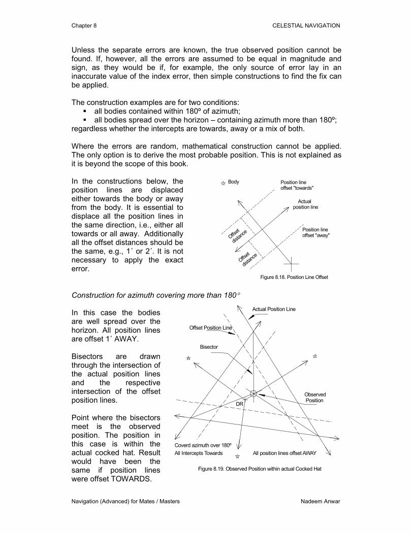
regardless whether the intercepts are towards, away or a mix of both. Where the errors are random, mathematical construction cannot be applied. The only option is to derive the most probable position. This is not explained as it is beyond the scope of this book. In the constructions below, the position lines are displaced either towards the body or away from the body. It is essential to displace all the position lines in the same direction, i.e., either all towards or all away. Additionally all the offset distances should be the same, e.g., 1´ or 2´. It is not necessary to apply the exact error.
Body
Actualposition line
Position lineoffset "away"
Position lineoffset "towards"
Offset
dista
nce
Offs
et
dista
nce
Figure 8.18. Position Line Offset
Construction for azimuth covering more than 180° In this case the bodies are well spread over the horizon. All position lines are offset 1´ AWAY. Bisectors are drawn through the intersection of the actual position lines and the respective intersection of the offset position lines. Point where the bisectors meet is the observed position. The position in this case is within the actual cocked hat. Result would have been the same if position lines were offset TOWARDS.
Actual Position Line
Offset Position Line
Observed Position
DR
All position lines offset AWAY
Coverd azimuth over 180º
Bisector
Figure 8.19. Observed Position within actual Cocked Hat
All Intercepts Towards
Chapter 8 CELESTIAL NAVIGATION
Navigation (Advanced) for Mates / Masters Nadeem Anwar
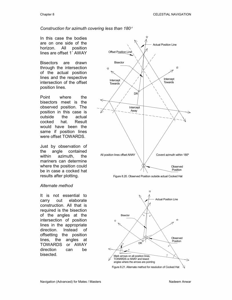
Construction for azimuth covering less than 180° In this case the bodies are on one side of the horizon. All position lines are offset 1´ AWAY Bisectors are drawn through the intersection of the actual position lines and the respective intersection of the offset position lines. Point where the bisectors meet is the observed position. The position in this case is outside the actual cocked hat. Result would have been the same if position lines were offset TOWARDS. Just by observation of the angle contained within azimuth, the mariners can determine where the position could be in case a cocked hat results after plotting.
Actual Position Line
Offset Position Line
Observed Position
DR
All position lines offset AWAY Coverd azimuth within 180º
Bisector
Figure 8.20. Observed Position outside actual Cocked Hat
Intercept Away
InterceptTowards
InterceptTowards
Alternate method It is not essential to carry out elaborate construction. All that is required is the bisection of the angles at the intersection of position lines in the appropriate direction. Instead of offsetting the position lines, the angles at TOWARDS or AWAY direction can be bisected.
Actual Position Line
Observed Position
DR
Bisector
Figure 8.21. Alternate method for resolution of Cocked Hat
Mark arrows on all position lines,TOWARDS or AWAY and bisectangles where the arrows are pointing
Chapter 8 CELESTIAL NAVIGATION
Navigation (Advanced) for Mates / Masters Nadeem Anwar
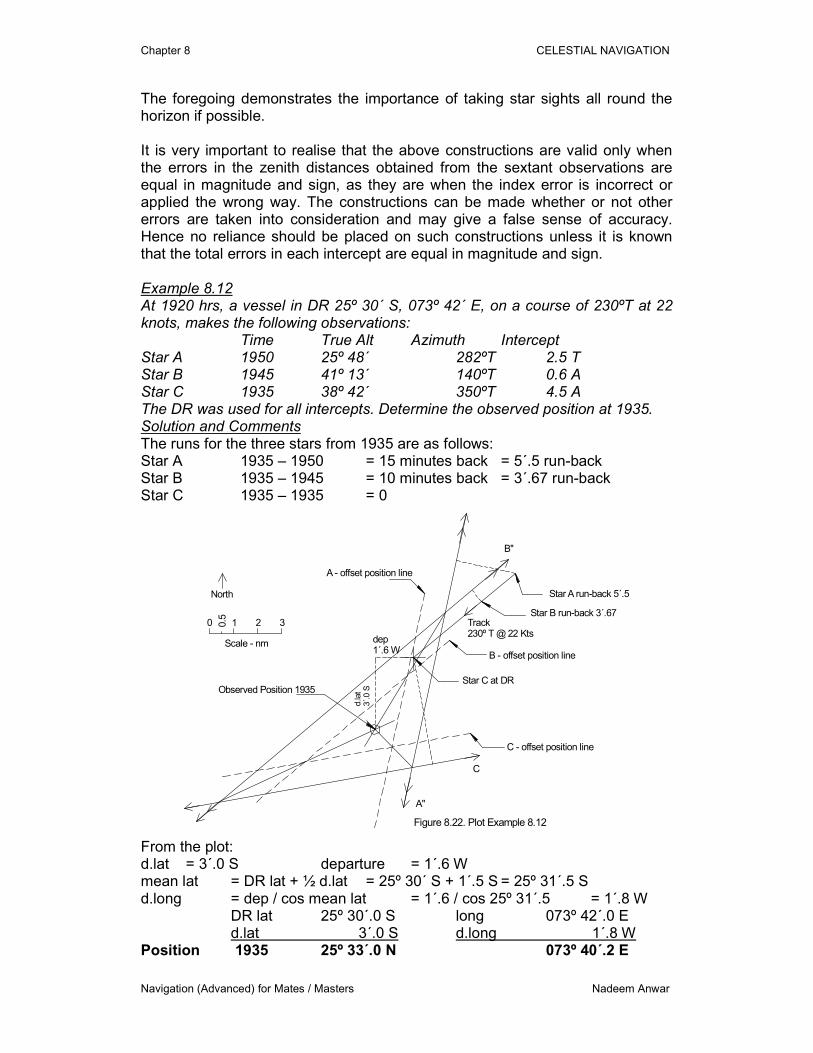
The foregoing demonstrates the importance of taking star sights all round the horizon if possible. It is very important to realise that the above constructions are valid only when the errors in the zenith distances obtained from the sextant observations are equal in magnitude and sign, as they are when the index error is incorrect or applied the wrong way. The constructions can be made whether or not other errors are taken into consideration and may give a false sense of accuracy. Hence no reliance should be placed on such constructions unless it is known that the total errors in each intercept are equal in magnitude and sign. Example 8.12 At 1920 hrs, a vessel in DR 25º 30´ S, 073º 42´ E, on a course of 230ºT at 22 knots, makes the following observations: Time True Alt Azimuth Intercept Star A 1950 25º 48´ 282ºT 2.5 T Star B 1945 41º 13´ 140ºT 0.6 A Star C 1935 38º 42´ 350ºT 4.5 A The DR was used for all intercepts. Determine the observed position at 1935. Solution and Comments The runs for the three stars from 1935 are as follows: Star A 1935 – 1950 = 15 minutes back = 5´.5 run-back Star B 1935 – 1945 = 10 minutes back = 3´.67 run-back Star C 1935 – 1935 = 0
Star C at DR
Star B run-back 3´.67
Star A run-back 5´.5
0.50 1 2 3
North
Scale - nm
C
A"
B"
C - offset position line
B - offset position line
A - offset position line
d.la
t3´.
0 S
dep1´.6 W
Track230º T @ 22 Kts
Observed Position 1935
Figure 8.22. Plot Example 8.12
From the plot: d.lat = 3´.0 S departure = 1´.6 W mean lat = DR lat + ½ d.lat = 25º 30´ S + 1´.5 S = 25º 31´.5 S d.long = dep / cos mean lat = 1´.6 / cos 25º 31´.5 = 1´.8 W
DR lat 25º 30´.0 S long 073º 42´.0 E d.lat 3´.0 S d.long 1´.8 W
Position 1935 25º 33´.0 N 073º 40´.2 E
Chapter 8 CELESTIAL NAVIGATION
Navigation (Advanced) for Mates / Masters Nadeem Anwar
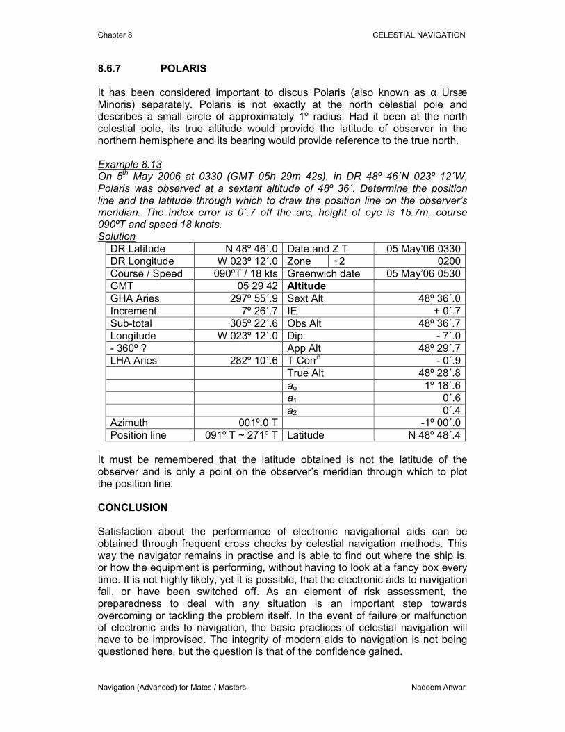
8.6.7 POLARIS It has been considered important to discus Polaris (also known as α Ursæ Minoris) separately. Polaris is not exactly at the north celestial pole and describes a small circle of approximately 1º radius. Had it been at the north celestial pole, its true altitude would provide the latitude of observer in the northern hemisphere and its bearing would provide reference to the true north. Example 8.13 On 5th May 2006 at 0330 (GMT 05h 29m 42s), in DR 48º 46´N 023º 12´W, Polaris was observed at a sextant altitude of 48º 36´. Determine the position line and the latitude through which to draw the position line on the observer’s meridian. The index error is 0´.7 off the arc, height of eye is 15.7m, course 090ºT and speed 18 knots. Solution
DR Latitude N 48º 46´.0 Date and Z T 05 May’06 0330
DR Longitude W 023º 12´.0 Zone +2 0200
Course / Speed 090ºT / 18 kts Greenwich date 05 May’06 0530
GMT 05 29 42 Altitude
GHA Aries 297º 55´.9 Sext Alt 48º 36´.0
Increment 7º 26´.7 IE + 0´.7
Sub-total 305º 22´.6 Obs Alt 48º 36´.7
Longitude W 023º 12´.0 Dip - 7´.0
- 360º ? App Alt 48º 29´.7
LHA Aries 282º 10´.6 T Corrn - 0´.9
True Alt 48º 28´.8
ao 1º 18´.6
a1 0´.6
a2 0´.4
Azimuth 001º.0 T -1º 00´.0
Position line 091º T ~ 271º T Latitude N 48º 48´.4
It must be remembered that the latitude obtained is not the latitude of the observer and is only a point on the observer’s meridian through which to plot the position line. CONCLUSION Satisfaction about the performance of electronic navigational aids can be obtained through frequent cross checks by celestial navigation methods. This way the navigator remains in practise and is able to find out where the ship is, or how the equipment is performing, without having to look at a fancy box every time. It is not highly likely, yet it is possible, that the electronic aids to navigation fail, or have been switched off. As an element of risk assessment, the preparedness to deal with any situation is an important step towards overcoming or tackling the problem itself. In the event of failure or malfunction of electronic aids to navigation, the basic practices of celestial navigation will have to be improvised. The integrity of modern aids to navigation is not being questioned here, but the question is that of the confidence gained.