Embed Size (px)
Citation preview
CHAPTER 10
PHASE TRANSFORMATIONS IN METALS
PROBLEM SOLUTIONS
The Kinetics of Phase Transformations
10.1 Name the two stages involved in the formation of particles of a new phase. Briefly describe each.
Solution
The two stages involved in the formation of particles of a new phase are nucleation and growth. The
nucleation process involves the formation of normally very small particles of the new phase(s) which are stable
and capable of continued growth. The growth stage is simply the increase in size of the new phase particles.
Excerpts from this work may be reproduced by instructors for distribution on a not-for-profit basis for testing or instructional purposes only to students enrolled in courses for which the textbook has been adopted. Any other reproduction or translation of this work beyond that permitted by Sections 107 or 108 of the 1976 United States Copyright Act without the permission of the copyright owner is unlawful.

10.2 (a) Rewrite the expression for the total free energy change for nucleation (Equation 10.1) for the
case of a cubic nucleus of edge length a (instead of a sphere of radius r). Now differentiate this expression with
respect to a (per Equation 10.2) and solve for both the critical cube edge length, a*, and also ΔG*.
(b) Is ΔG* greater for a cube or a sphere? Why?
Solution
(a) This problem first asks that we rewrite the expression for the total free energy change for nucleation
(analogous to Equation 10.1) for the case of a cubic nucleus of edge length a. The volume of such a cubic radius
is a3, whereas the total surface area is 6a2 (since there are six faces each of which has an area of a2). Thus, the
expression for G is as follows:
€
G =a3Gv + 6a2γ
Differentiation of this expression with respect to a is as
€
dGda
=d(a3ΔGv)
da+
d (6a2γ)da
€
=3a2Gv + 12aγ
If we set this expression equal to zero as
€
3a2Gv + 12aγ=0
and then solve for a (= a*), we have
€
a* =−4γGv
Substitution of this expression for a in the above expression for G yields an equation for G* as
€
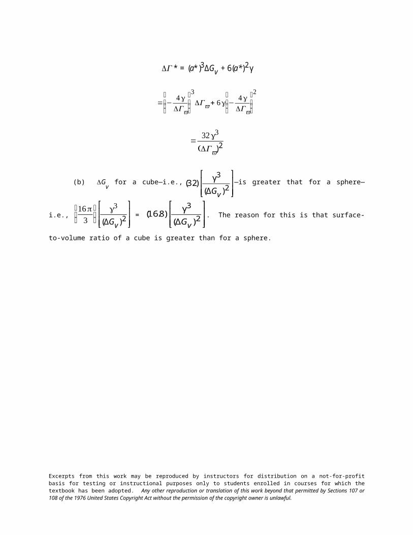
G* = (a*)3ΔGv + 6(a*)2 γ
€
= −4γGv
⎛
⎝ ⎜ ⎜
⎞
⎠ ⎟ ⎟
3
Gv + 6γ −4γGv
⎛
⎝ ⎜ ⎜
⎞
⎠ ⎟ ⎟
2
Excerpts from this work may be reproduced by instructors for distribution on a not-for-profit basis for testing or instructional purposes only to students enrolled in courses for which the textbook has been adopted. Any other reproduction or translation of this work beyond that permitted by Sections 107 or 108 of the 1976 United States Copyright Act without the permission of the copyright owner is unlawful.
€
=32γ3
(Gv)2
(b) Gv for a cube—i.e.,
€
(32)γ3
(ΔGv)2
⎡
⎣ ⎢ ⎢
⎤
⎦ ⎥ ⎥—is greater that for a sphere—i.e.,
€
16π3
⎛ ⎝ ⎜
⎞ ⎠ ⎟
γ3
(ΔGv)2
⎡
⎣ ⎢ ⎢
⎤
⎦ ⎥ ⎥ =
€
(16.8)γ3
(ΔGv)2
⎡
⎣ ⎢ ⎢
⎤
⎦ ⎥ ⎥. The reason for this is that surface-to-volume ratio of a cube is greater than for a sphere.
Excerpts from this work may be reproduced by instructors for distribution on a not-for-profit basis for testing or instructional purposes only to students enrolled in courses for which the textbook has been adopted. Any other reproduction or translation of this work beyond that permitted by Sections 107 or 108 of the 1976 United States Copyright Act without the permission of the copyright owner is unlawful.

10.3 If copper (which has a melting point of 1085°C) homogeneously nucleates at 849°C, calculate the
critical radius given values of –1.77 × 10⁹ J/m3 and 0.200 J/m2, respectively, for the latent heat of fusion and the
surface free energy.
Solution
This problem states that copper homogeneously nucleates at 849 C, and that we are to calculate the
critical radius given the latent heat of fusion (–1.77 109 J/m3) and the surface free energy (0.200 J/m2).
Solution to this problem requires the utilization of Equation 10.6 as
€
r * = −2 γTmΔH f
⎛
⎝
⎜ ⎜
⎞
⎠
⎟ ⎟
1Tm − T
⎛
⎝ ⎜ ⎜
⎞
⎠ ⎟ ⎟
€
= −(2)(0.200 J /m2) (1085 + 273 K)
−1.77 × 10⁹ J /m3
⎡
⎣ ⎢
⎤
⎦ ⎥
1
1085°C − 849°C
⎛
⎝ ⎜
⎞
⎠ ⎟
€
=1.30 × 10⁻⁹ m = 1.30 nm
Excerpts from this work may be reproduced by instructors for distribution on a not-for-profit basis for testing or instructional purposes only to students enrolled in courses for which the textbook has been adopted. Any other reproduction or translation of this work beyond that permitted by Sections 107 or 108 of the 1976 United States Copyright Act without the permission of the copyright owner is unlawful.

10.4 (a) For the solidification of iron, calculate the critical radius r* and the activation free energy ΔG*
if nucleation is homogeneous. Values for the latent heat of fusion and surface free energy are –1.85 × 10 9 J/m3
and 0.204 J/m2, respectively. Use the supercooling value found in Table 10.1.
(b) Now calculate the number of atoms found in a nucleus of critical size. Assume a lattice parameter of
0.292 nm for solid iron at its melting temperature.
Solution
(a) This portion of the problem asks that we compute r* and G* for the homogeneous nucleation of the
solidification of Fe. First of all, Equation 10.6 is used to compute the critical radius. The melting temperature for
iron, found inside the front cover is 1538C; also values of Hf (–1.85 109 J/m3) and γ (0.204 J/m2) are given
in the problem statement, and the supercooling value found in Table 10.1 is 295 C (or 295 K). Thus, from
Equation 10.6 we have
€
r * = −2γTm
ΔH f
⎛
⎝ ⎜ ⎜
⎞
⎠ ⎟ ⎟
1Tm − T
⎛
⎝ ⎜ ⎜
⎞
⎠ ⎟ ⎟
€
= −(2)(0.204 J /m2) (1538 + 273 K)
−1.85 × 10⁹ J /m3
⎡
⎣ ⎢
⎤
⎦ ⎥
1
295 K
⎛
⎝ ⎜
⎞
⎠ ⎟
=
€
1.35 × 10⁻⁹ m = 1.35 nm
For computation of the activation free energy, Equation 10.7 is employed. Thus
€
G* =16 π γ3Tm
2
3ΔH f2
⎛
⎝ ⎜ ⎜
⎞
⎠ ⎟ ⎟
1
(Tm − T)2
€
=(16)(π)(0.204 J /m2) 3
(1538 + 273 K)2
(3)(−1.85 × 10⁹ J /m3)2
⎡
⎣ ⎢ ⎢
⎤
⎦ ⎥ ⎥
1
(295 K)2
⎡
⎣ ⎢
⎤
⎦ ⎥
€
=1.57 × 10⁻¹⁸ J
(b) In order to compute the number of atoms in a nucleus of critical size (assuming a spherical nucleus of
radius r*), it is first necessary to determine the number of unit cells, which we then multiply by the number of
atoms per unit cell. The number of unit cells found in this critical nucleus is just the ratio of critical nucleus and
unit cell volumes. Inasmuch as iron has the BCC crystal structure, its unit cell volume is just a3 where a is the
Excerpts from this work may be reproduced by instructors for distribution on a not-for-profit basis for testing or instructional purposes only to students enrolled in courses for which the textbook has been adopted. Any other reproduction or translation of this work beyond that permitted by Sections 107 or 108 of the 1976 United States Copyright Act without the permission of the copyright owner is unlawful.

unit cell length (i.e., the lattice parameter); this value is 0.292 nm, as cited in the problem statement. Therefore,
the number of unit cells found in a radius of critical size is just
€
# unit cells / particle =
4
3πr *3
a3
€
=
4
3
⎛ ⎝ ⎜
⎞ ⎠ ⎟(π)(1.35 nm)3
(0.292 nm)3= 414 unit cells
Inasmuch as 2 atoms are associated with each BCC unit cell, the total number of atoms per critical nucleus is just
€
(414 unit cells / critical nucleus)(2 atoms /unit cell) = 828 atoms /critical nucleus
Excerpts from this work may be reproduced by instructors for distribution on a not-for-profit basis for testing or instructional purposes only to students enrolled in courses for which the textbook has been adopted. Any other reproduction or translation of this work beyond that permitted by Sections 107 or 108 of the 1976 United States Copyright Act without the permission of the copyright owner is unlawful.

10.5 (a) Assume for the solidification of iron (Problem 10.4) that nucleation is homogeneous, and the
number of stable nuclei is 106 nuclei per cubic meter. Calculate the critical radius and the number of stable nuclei
that exist at the following degrees of supercooling: 200 K and 300 K.
(b) What is significant about the magnitudes of these critical radii and the numbers of stable nuclei?
Solution
(a) For this part of the problem we are asked to calculate the critical radius for the solidification of iron
(per Problem 10.4), for 200 K and 300 K degrees of supercooling, and assuming that the there are 10 6 nuclei per
meter cubed for homogeneous nucleation. In order to calculate the critical radii, we replace the Tm – T term in
Equation 10.6 by the degree of supercooling (denoted as T) cited in the problem.
For 200 K supercooling,
€
r200* = −
2 γTm
ΔH f
⎛
⎝ ⎜ ⎜
⎞
⎠ ⎟ ⎟
1
ΔT
⎛
⎝ ⎜
⎞
⎠ ⎟
€
= −(2)(0.204 J /m2) (1538 + 273 K)
−1.85 × 10 9 J /m3
⎡
⎣ ⎢
⎤
⎦ ⎥
1
200 K
⎛
⎝ ⎜
⎞
⎠ ⎟
= 2.00 10-9 m = 2.00 nm
And, for 300 K supercooling,
€
r300* = −
(2)(0.204 J /m2) (1538 + 273 K)
−1.85 × 10 9 J /m3
⎡
⎣ ⎢
⎤
⎦ ⎥
1
300 K
⎛
⎝ ⎜
⎞
⎠ ⎟
= 1.33 10-9 m = 1.33 nm
In order to compute the number of stable nuclei that exist at 200 K and 300 K degrees of supercooling, it
is necessary to use Equation 10.8. However, we must first determine the value of K1 in Equation 10.8, which in
turn requires that we calculate G* at the homogeneous nucleation temperature using Equation 10.7; this was
done in Problem 10.4, and yielded a value of G* = 1.57 10-18 J. Now for the computation of K1, using the
value of n* for at the homogenous nucleation temperature (106 nuclei/m3):
€
K1 =n*
exp −ΔG *
kT
⎛
⎝ ⎜
⎞
⎠ ⎟
Excerpts from this work may be reproduced by instructors for distribution on a not-for-profit basis for testing or instructional purposes only to students enrolled in courses for which the textbook has been adopted. Any other reproduction or translation of this work beyond that permitted by Sections 107 or 108 of the 1976 United States Copyright Act without the permission of the copyright owner is unlawful.

€
=106 nuclei /m3
exp −1.57 × 10⁻¹⁸ J
(1.38 × 10⁻²³ J / atom− K) (1538°C − 295°C)
⎡
⎣ ⎢
⎤
⎦ ⎥
= 5.62 1045 nuclei/m3
Now for 200 K supercooling, it is first necessary to recalculate the value G* of using Equation 10.7, where,
again, the Tm – T term is replaced by the number of degrees of supercooling, denoted as T, which in this case is
200 K. Thus
€
G200* =
16 π γ3Tm2
3ΔH f2
⎛
⎝ ⎜ ⎜
⎞
⎠ ⎟ ⎟
1
(ΔT)2
€
=(16)(π)(0.204 J /m2)3 (1538 + 273 K)2
(3)(−1.85 × 10⁹ J /m3)2
⎡
⎣ ⎢
⎤
⎦ ⎥
1
(200 K)2
⎡
⎣ ⎢
⎤
⎦ ⎥
= 3.41 10-18 J
And, from Equation 10.8, the value of n* is
€
n200* = K1 exp −
ΔG200*
kT
⎛
⎝ ⎜ ⎜
⎞
⎠ ⎟ ⎟
€
=(5.62 × 1045 nuclei /m3)exp −3.41 × 10⁻¹⁸ J
(1.38 × 10⁻²³ J / atom− K) (1538 K − 200 K)
⎡
⎣ ⎢
⎤
⎦ ⎥
= 3.5 10-35 stable nuclei
Now, for 300 K supercooling the value of G* is equal to
€
G300* =
(16)(π)(0.204 J /m2)3 (1538 + 273 K)2
(3)(−1.85 × 10⁹ J /m3)2
⎡
⎣ ⎢
⎤
⎦ ⎥
1
(300 K)2
⎡
⎣ ⎢
⎤
⎦ ⎥
= 1.51 10-18 J
Excerpts from this work may be reproduced by instructors for distribution on a not-for-profit basis for testing or instructional purposes only to students enrolled in courses for which the textbook has been adopted. Any other reproduction or translation of this work beyond that permitted by Sections 107 or 108 of the 1976 United States Copyright Act without the permission of the copyright owner is unlawful.

from which we compute the number of stable nuclei at 300 K of supercooling as
€
n300* = K1 exp −
ΔG300*
kT
⎛
⎝ ⎜ ⎜
⎞
⎠ ⎟ ⎟
€
*n =(5.62 × 1045 nuclei /m3)exp −1.51 × 10⁻¹⁸ J
(1.38 × 10⁻²³ J / atom− K) (1538 K − 300 K)
⎡
⎣ ⎢
⎤
⎦ ⎥
= 2.32 107 stable nuclei
(b) Relative to critical radius, r* for 300 K supercooling is slightly smaller that for 200 K (1.33 nm
versus 2.00 nm). [From Problem 10.4, the value of r* at the homogeneous nucleation temperature (295 K) was
1.35 nm.] More significant, however, are the values of n* at these two degrees of supercooling, which are
dramatically different—3.5 10-35 stable nuclei at T = 200 K, versus 2.32 107 stable nuclei at T = 300 K!
Excerpts from this work may be reproduced by instructors for distribution on a not-for-profit basis for testing or instructional purposes only to students enrolled in courses for which the textbook has been adopted. Any other reproduction or translation of this work beyond that permitted by Sections 107 or 108 of the 1976 United States Copyright Act without the permission of the copyright owner is unlawful.

10.6 For some transformation having kinetics that obey the Avrami equation (Equation 10.17), the
parameter n is known to have a value of 1.7. If, after 100 s, the reaction is 50% complete, how long (total time)
will it take the transformation to go to 99% completion?
Solution
This problem calls for us to compute the length of time required for a reaction to go to 99% completion.
It first becomes necessary to solve for the parameter k in Equation 10.17. In order to do this it is best manipulate
the equation such that k is the dependent variable. We first rearrange Equation 10.17 as
€
exp(− kt n) = 1 − y
and then take natural logarithms of both sides:
−ktn = ln (1 − y)
Now solving for k gives
k = −
ln (1 − y)
t n
And, from the problem statement, for y = 0.50 when t = 100 s and given that n = 1.7, the value of k is equal to
€
k = −ln (1 − 0.5)
(100 s)1.7= 2.76 × 10⁻⁴
We now want to manipulate Equation 10.17 such that t is the dependent variable. The above equation may be
written in the form:
t n = −
ln (1 − y)
k
And solving this expression for t leads to
t = −
ln (1 − y)
k ⎡ ⎣ ⎢
⎤ ⎦ ⎥
1/n
Excerpts from this work may be reproduced by instructors for distribution on a not-for-profit basis for testing or instructional purposes only to students enrolled in courses for which the textbook has been adopted. Any other reproduction or translation of this work beyond that permitted by Sections 107 or 108 of the 1976 United States Copyright Act without the permission of the copyright owner is unlawful.

Now, using this equation and the value of k determined above, the time to 99% transformation completion is equal
to
€
t = −ln (1 − 0.99)
2.76 × 10⁻⁴
⎡
⎣ ⎢
⎤
⎦ ⎥
1/1.7
= 305 s
Excerpts from this work may be reproduced by instructors for distribution on a not-for-profit basis for testing or instructional purposes only to students enrolled in courses for which the textbook has been adopted. Any other reproduction or translation of this work beyond that permitted by Sections 107 or 108 of the 1976 United States Copyright Act without the permission of the copyright owner is unlawful.

10.7 Compute the rate of some reaction that obeys Avrami kinetics, assuming that the constants n and k
have values of 3.0 and 7 10-3, respectively, for time expressed in seconds.
Solution
This problem asks that we compute the rate of some reaction given the values of n and k in Equation
10.17. Since the reaction rate is defined by Equation 10.18, it is first necessary to determine t0.5, or the time
necessary for the reaction to reach y = 0.5. We must first manipulate Equation 10.17 such that t is the dependent
variable. We first rearrange Equation 10.17 as
€
exp(− kt n) = 1 − y
and then take natural logarithms of both sides:
€
−ktn = ln (1 − y)
which my be rearranged so as to read
€
tn =−ln (1 − y)
k
Now, solving for t from this expression leads to
€
t = −ln (1 − y)
k
⎡
⎣ ⎢ ⎤
⎦ ⎥1/n
For t0.5 this equation takes the form
€
t0.5 = −ln (1 − 0.5)
k
⎡
⎣ ⎢ ⎤
⎦ ⎥1/n
And, incorporation of values for n and k given in the problem statement (3.0 and 7 10-3, respectively), then
€
t0.5 = −ln (1 − 0.5)
7 × 10⁻³
⎡
⎣ ⎢
⎤
⎦ ⎥
1/3.0
= 4.63 s
Excerpts from this work may be reproduced by instructors for distribution on a not-for-profit basis for testing or instructional purposes only to students enrolled in courses for which the textbook has been adopted. Any other reproduction or translation of this work beyond that permitted by Sections 107 or 108 of the 1976 United States Copyright Act without the permission of the copyright owner is unlawful.
Now, the rate is computed using Equation 10.18 as
€
rate =1
t0.5=
1
4.63 s= 0.216 s-1
Excerpts from this work may be reproduced by instructors for distribution on a not-for-profit basis for testing or instructional purposes only to students enrolled in courses for which the textbook has been adopted. Any other reproduction or translation of this work beyond that permitted by Sections 107 or 108 of the 1976 United States Copyright Act without the permission of the copyright owner is unlawful.

10.8 It is known that the kinetics of recrystallization for some alloy obey the Avrami equation and that
the value of n in the exponential is 2.5. If, at some temperature, the fraction recrystallized is 0.40 after 200 min,
determine the rate of recrystallization at this temperature.
Solution
This problem gives us the value of y (0.40) at some time t (200 min), and also the value of n (2.5) for the
recrystallization of an alloy at some temperature, and then asks that we determine the rate of recrystallization at
this same temperature. It is first necessary to calculate the value of k. We first rearrange Equation 10.17 as
€
exp(− kt n) = 1 − y
and then take natural logarithms of both sides:
€
−ktn = ln (1 − y)
Now solving for k gives
€
k =−ln (1 − y)
t n
which, using the values cited above for y, n, and t yields
€
k = −ln (1 − 0.40)
(200 min)2.5= 9.0 × 10⁻⁷
At this point we want to compute t0.5, the value of t for y = 0.5, which means that it is necessary to establish a
form of Equation 10.17 in which t is the dependent variable. From one of the above equations
€
tn =−ln (1 − y)
k
And solving this expression for t leads to
Excerpts from this work may be reproduced by instructors for distribution on a not-for-profit basis for testing or instructional purposes only to students enrolled in courses for which the textbook has been adopted. Any other reproduction or translation of this work beyond that permitted by Sections 107 or 108 of the 1976 United States Copyright Act without the permission of the copyright owner is unlawful.

€
t = −ln (1 − y)
k
⎡
⎣ ⎢ ⎤
⎦ ⎥
1/n
For t0.5, this equation takes the form
€
t0.5 = −ln (1 − 0.5)
k
⎡
⎣ ⎢ ⎤
⎦ ⎥1/n
and incorporation of the value of k determined above, as well as the value of n cited in the problem statement (2.5), then t0.5 is equal to
€
t0.5 = −ln (1 − 0.5)
9.0 × 10⁻⁷
⎡
⎣ ⎢
⎤
⎦ ⎥
1/2.5
= 226.3 min
Therefore, from Equation 10.18, the rate is just
€
rate =1
t0.5=
1
226.3 min= 4.42 × 10⁻³ (min)-1
Excerpts from this work may be reproduced by instructors for distribution on a not-for-profit basis for testing or instructional purposes only to students enrolled in courses for which the textbook has been adopted. Any other reproduction or translation of this work beyond that permitted by Sections 107 or 108 of the 1976 United States Copyright Act without the permission of the copyright owner is unlawful.

10.9 The kinetics of the austenite-to-pearlite transformation obey the Avrami relationship. Using the
fraction transformed–time data given here, determine the total time required for 95% of the austenite to transform
to pearlite:
Fraction Transformed Time (s)
0.2 12.6
0.8 28.2
Solution
The first thing necessary is to set up two expressions of the form of Equation 10.17, and then to solve
simultaneously for the values of n and k. In order to expedite this process, we will rearrange and do some
algebraic manipulation of Equation 10.17. First of all, we rearrange as follows:
€
1 − y=exp − kt n( )
Now taking natural logarithms
€
ln (1 − y) = − kt n
Or
€
−ln (1 − y) = kt n
which may also be expressed as
€
ln1
1 − y
⎛
⎝ ⎜
⎞
⎠ ⎟= kt n
Now taking natural logarithms again, leads to
€
ln ln1
1 − y
⎛
⎝ ⎜
⎞
⎠ ⎟
⎡
⎣ ⎢
⎤
⎦ ⎥= ln k + n ln t
Excerpts from this work may be reproduced by instructors for distribution on a not-for-profit basis for testing or instructional purposes only to students enrolled in courses for which the textbook has been adopted. Any other reproduction or translation of this work beyond that permitted by Sections 107 or 108 of the 1976 United States Copyright Act without the permission of the copyright owner is unlawful.

which is the form of the equation that we will now use. Using values cited in the problem statement, the two
equations are thus
€
ln ln1
1 − 0.2
⎡
⎣ ⎢
⎤
⎦ ⎥
⎧ ⎨ ⎩
⎫ ⎬ ⎭= ln k + n ln (12.6 s)
€
ln ln1
1 − 0.8
⎡
⎣ ⎢
⎤
⎦ ⎥
⎧ ⎨ ⎩
⎫ ⎬ ⎭= ln k + n ln (28.2 s)
Solving these two expressions simultaneously for n and k yields n = 2.453 and k = 4.46 10-4.
Now it becomes necessary to solve for the value of t at which y = 0.95. One of the above equations—viz
€
−ln (1 − y) = kt n
may be rewritten as
€
tn =−ln (1 − y)
k
And solving for t leads to
€
t = −ln (1 − y)
k
⎡
⎣ ⎢ ⎤
⎦ ⎥1/n
Now incorporating into this expression values for n and k determined above, the time required for 95% austenite
transformation is equal to
€
t = −ln (1 − 0.95)
4.64 × 10⁻⁴
⎡
⎣ ⎢
⎤
⎦ ⎥
1/2.453
= 35.7 s
Excerpts from this work may be reproduced by instructors for distribution on a not-for-profit basis for testing or instructional purposes only to students enrolled in courses for which the textbook has been adopted. Any other reproduction or translation of this work beyond that permitted by Sections 107 or 108 of the 1976 United States Copyright Act without the permission of the copyright owner is unlawful.

10.10 The fraction recrystallized–time data for the recrystallization at 600°C of a previously deformed
steel are tabulated here. Assuming that the kinetics of this process obey the Avrami relationship, determine the
fraction recrystallized after a total time of 22.8 min.
Fraction Recrystallized
Time (min)
0.20 13.1
0.70 29.1
Solution
The first thing necessary is to set up two expressions of the form of Equation 10.17, and then to solve
simultaneously for the values of n and k. In order to expedite this process, we will rearrange and do some
algebraic manipulation of Equation 10.17. First of all, we rearrange as follows:
€
1 − y = exp − kt n( )
Now taking natural logarithms
€
ln (1 − y) = − kt n
Or
€
−ln (1 − y) = kt n
which may also be expressed as
€
ln1
1 − y
⎛
⎝ ⎜
⎞
⎠ ⎟= kt n
Now taking natural logarithms again, leads to
€
ln ln1
1 − y
⎛
⎝ ⎜
⎞
⎠ ⎟
⎡
⎣ ⎢
⎤
⎦ ⎥= ln k + n ln t
Excerpts from this work may be reproduced by instructors for distribution on a not-for-profit basis for testing or instructional purposes only to students enrolled in courses for which the textbook has been adopted. Any other reproduction or translation of this work beyond that permitted by Sections 107 or 108 of the 1976 United States Copyright Act without the permission of the copyright owner is unlawful.

which is the form of the equation that we will now use. The two equations are thus
€
ln ln1
1 − 0.20
⎡
⎣ ⎢
⎤
⎦ ⎥
⎧ ⎨ ⎩
⎫ ⎬ ⎭= ln k + n ln (13.1 min)
€
ln ln1
1 − 0.70
⎡
⎣ ⎢
⎤
⎦ ⎥
⎧ ⎨ ⎩
⎫ ⎬ ⎭= ln k + n ln (29.1 min)
Solving these two expressions simultaneously for n and k yields n = 2.112 and k = 9.75 10-4.
Now it becomes necessary to solve for y when t = 22.8 min. Application of Equation 10.17 leads to
€
y=1 − exp−ktn( )
€
= 1 − exp − (9.75 × 10⁻⁴ )(22.8 min)2.112[ ] = 0.51
Excerpts from this work may be reproduced by instructors for distribution on a not-for-profit basis for testing or instructional purposes only to students enrolled in courses for which the textbook has been adopted. Any other reproduction or translation of this work beyond that permitted by Sections 107 or 108 of the 1976 United States Copyright Act without the permission of the copyright owner is unlawful.

10.11 (a) From the curves shown in Figure 10.11 and using Equation 10.18, determine the rate of
recrystallization for pure copper at the several temperatures.
(b) Make a plot of ln(rate) versus the reciprocal of temperature (in K–1), and determine the activation
energy for this recrystallization process. (See Section 5.5.)
(c) By extrapolation, estimate the length of time required for 50% recrystallization at room temperature,
20°C (293 K).
Solution
This problem asks us to consider the percent recrystallized versus logarithm of time curves for copper
shown in Figure 10.11.
(a) The rates at the different temperatures are determined using Equation 10.18, which rates are
tabulated below:
Temperature (C) Rate (min)-1
135 0.105
119 4.4 10-2
113 2.9 10-2
102 1.25 10-2
88 4.2 10-3
43 3.8 10-5
(b) These data are plotted below.
Excerpts from this work may be reproduced by instructors for distribution on a not-for-profit basis for testing or instructional purposes only to students enrolled in courses for which the textbook has been adopted. Any other reproduction or translation of this work beyond that permitted by Sections 107 or 108 of the 1976 United States Copyright Act without the permission of the copyright owner is unlawful.

The activation energy, Q, is related to the slope of the line drawn through the data points as
€
Q =−Slope(R)
where R is the gas constant. The slope of this line is equal to
€
Slope = Δ ln rate
Δ1
T
⎛
⎝ ⎜
⎞
⎠ ⎟
= ln rate1 − ln rate2
1
T1 −
1
T2
Let us take 1/T1 = 0.0025 K-1 and 1/T2 = 0.0031 K-1; the corresponding ln rate values are ln rate1 = -2.6 and ln
rate2 = -9.4. Thus, using these values, the slope is equal to
€
Slope = −2.6 − (−9.4)
0.0025 K-1 − 0.0031 K-1 = −1.133 × 10⁴ K
And, finally the activation energy is
€
Q = − (Slope)(R) = − (−1.133 × 10⁴ K-1) (8.31 J/mol- K)
= 94,150 J/mol
(c) At room temperature (20C), 1/T = 1/(20 + 273 K) = 3.41 10-3 K-1. Extrapolation of the data in
the plot to this 1/T value gives
€
( )ln rate≅ −12.8
which leads to
€
rate ≅ exp (−12.8) = 2.76 × 10⁻⁶ (min)-1
But since
Excerpts from this work may be reproduced by instructors for distribution on a not-for-profit basis for testing or instructional purposes only to students enrolled in courses for which the textbook has been adopted. Any other reproduction or translation of this work beyond that permitted by Sections 107 or 108 of the 1976 United States Copyright Act without the permission of the copyright owner is unlawful.
€
rate=1t0.5
€
t0.5 =1
rate=
1
2.76 × 10⁻⁶ (min)−1
€
=3.62 × 10⁵ min = 250 days
Excerpts from this work may be reproduced by instructors for distribution on a not-for-profit basis for testing or instructional purposes only to students enrolled in courses for which the textbook has been adopted. Any other reproduction or translation of this work beyond that permitted by Sections 107 or 108 of the 1976 United States Copyright Act without the permission of the copyright owner is unlawful.

10.12 Determine values for the constants n and k (Equation 10.17) for the recrystallization of copper
(Figure 10.11) at 102°C.
Solution
In this problem we are asked to determine, from Figure 10.11, the values of the constants n and k
(Equation 10.17) for the recrystallization of copper at 102C. One way to solve this problem is to take two values
of percent recrystallization (which is just 100y, Equation 10.17) and their corresponding time values, then set up
two simultaneous equations, from which n and k may be determined. In order to expedite this process, we will
rearrange and do some algebraic manipulation of Equation 10.17. First of all, we rearrange as follows:
€
1 − y=exp − kt n( )
Now taking natural logarithms
€
ln (1 − y) = − kt n
Or
€
−ln (1 − y) = kt n
which may also be expressed as
€
ln1
1 − y
⎛
⎝ ⎜
⎞
⎠ ⎟= kt n
Now taking natural logarithms again, leads to
€
ln ln1
1 − y
⎛
⎝ ⎜
⎞
⎠ ⎟
⎡
⎣ ⎢
⎤
⎦ ⎥= ln k + n ln t
which is the form of the equation that we will now use. From the 102 C curve of Figure 10.11, let us arbitrarily
choose two percent recrystallized values, 20% and 80% (i.e., y1 = 0.20 and y2 = 0.80). Their corresponding time
values are t1 = 50 min and t2 = 100 min (realizing that the time axis is scaled logarithmically). Thus, our two
simultaneous equations become
Excerpts from this work may be reproduced by instructors for distribution on a not-for-profit basis for testing or instructional purposes only to students enrolled in courses for which the textbook has been adopted. Any other reproduction or translation of this work beyond that permitted by Sections 107 or 108 of the 1976 United States Copyright Act without the permission of the copyright owner is unlawful.
€
ln ln1
1 − 0.2
⎛
⎝ ⎜
⎞
⎠ ⎟
⎡
⎣ ⎢
⎤
⎦ ⎥= ln k + n ln (50)
€
ln ln1
1 − 0.8
⎛
⎝ ⎜
⎞
⎠ ⎟
⎡
⎣ ⎢
⎤
⎦ ⎥= ln k + n ln (100)
from which we obtain the values n = 2.85 and k = 3.21 10-6.
Excerpts from this work may be reproduced by instructors for distribution on a not-for-profit basis for testing or instructional purposes only to students enrolled in courses for which the textbook has been adopted. Any other reproduction or translation of this work beyond that permitted by Sections 107 or 108 of the 1976 United States Copyright Act without the permission of the copyright owner is unlawful.

Metastable Versus Equilibrium States
10.13 In terms of heat treatment and the development of microstructure, what are two major limitations
of the iron–iron carbide phase diagram?
Solution
Two limitations of the iron-iron carbide phase diagram are:
(1) The nonequilibrium martensite does not appear on the diagram; and
(2) The diagram provides no indication as to the time-temperature relationships for the formation of
pearlite, bainite, and spheroidite, all of which are composed of the equilibrium ferrite and cementite phases.
Excerpts from this work may be reproduced by instructors for distribution on a not-for-profit basis for testing or instructional purposes only to students enrolled in courses for which the textbook has been adopted. Any other reproduction or translation of this work beyond that permitted by Sections 107 or 108 of the 1976 United States Copyright Act without the permission of the copyright owner is unlawful.

10.14 (a) Briefly describe the phenomena of superheating and supercooling.
(b) Why do these phenomena occur?
Solution
(a) Superheating and supercooling correspond, respectively, to heating or cooling above or below a
phase transition temperature without the occurrence of the transformation.
(b) These phenomena occur because right at the phase transition temperature, the driving force is not
sufficient to cause the transformation to occur. The driving force is enhanced during superheating or
supercooling.
Excerpts from this work may be reproduced by instructors for distribution on a not-for-profit basis for testing or instructional purposes only to students enrolled in courses for which the textbook has been adopted. Any other reproduction or translation of this work beyond that permitted by Sections 107 or 108 of the 1976 United States Copyright Act without the permission of the copyright owner is unlawful.

Isothermal Transformation Diagrams
10.15 Suppose that a steel of eutectoid composition is cooled to 550°C (1020°F) from 760°C (1400°F) in
less than 0.5 s and held at this temperature.
(a) How long will it take for the austenite-to-pearlite reaction to go to 50% completion? To 100%
completion?
(b) Estimate the hardness of the alloy that has completely transformed to pearlite.
Solution
We are called upon to consider the isothermal transformation of an iron-carbon alloy of eutectoid
composition.
(a) From Figure 10.22, a horizontal line at 550C intersects the 50% and reaction completion curves at
about 2.5 and 6 seconds, respectively; these are the times asked for in the problem statement.
(b) The pearlite formed will be fine pearlite. From Figure 10.30a, the hardness of an alloy of
composition 0.76 wt% C that consists of fine pearlite is about 265 HB (27 HRC).
Excerpts from this work may be reproduced by instructors for distribution on a not-for-profit basis for testing or instructional purposes only to students enrolled in courses for which the textbook has been adopted. Any other reproduction or translation of this work beyond that permitted by Sections 107 or 108 of the 1976 United States Copyright Act without the permission of the copyright owner is unlawful.

10.16 Briefly cite the differences between pearlite, bainite, and spheroidite relative to microstructure
and mechanical properties.
Solution
The microstructures of pearlite, bainite, and spheroidite all consist of -ferrite and cementite phases. For
pearlite, the two phases exist as layers which alternate with one another. Bainite consists of very fine and parallel
needle-shaped particles of cementite that are surrounded an -ferrite matrix. For spheroidite, the matrix is ferrite,
and the cementite phase is in the shape of sphere-shaped particles.
Bainite is harder and stronger than pearlite, which, in turn, is harder and stronger than spheroidite.
Excerpts from this work may be reproduced by instructors for distribution on a not-for-profit basis for testing or instructional purposes only to students enrolled in courses for which the textbook has been adopted. Any other reproduction or translation of this work beyond that permitted by Sections 107 or 108 of the 1976 United States Copyright Act without the permission of the copyright owner is unlawful.

10.17 What is the driving force for the formation of spheroidite?
Solution
The driving force for the formation of spheroidite is the net reduction in ferrite-cementite phase boundary
area.
Excerpts from this work may be reproduced by instructors for distribution on a not-for-profit basis for testing or instructional purposes only to students enrolled in courses for which the textbook has been adopted. Any other reproduction or translation of this work beyond that permitted by Sections 107 or 108 of the 1976 United States Copyright Act without the permission of the copyright owner is unlawful.

10.18 Using the isothermal transformation diagram for an iron–carbon alloy of eutectoid composition
(Figure 10.22), specify the nature of the final microstructure (in terms of microconstituents present and
approximate percentages of each) of a small specimen that has been subjected to the following time–temperature
treatments. In each case assume that the specimen begins at 760°C (1400°F) and that it has been held at this
temperature long enough to have achieved a complete and homogeneous austenitic structure.
(a) Cool rapidly to 700°C (1290°F), hold for 104 s, then quench to room temperature.
Solution
Below is Figure 10.22 upon which is superimposed the above heat treatment.
After cooling and holding at 700°C for 104 s, approximately 50% of the specimen has transformed to
coarse pearlite. Upon cooling to room temperature, the remaining 50% transforms to martensite. Hence, the final
microstructure consists of about 50% coarse pearlite and 50% martensite.
(b) Reheat the specimen in part (a) to 700°C (1290°F) for 20 h.
Solution
Excerpts from this work may be reproduced by instructors for distribution on a not-for-profit basis for testing or instructional purposes only to students enrolled in courses for which the textbook has been adopted. Any other reproduction or translation of this work beyond that permitted by Sections 107 or 108 of the 1976 United States Copyright Act without the permission of the copyright owner is unlawful.

Heating to 700°C for 20 h the specimen in part (a) will transform the coarse pearlite and martensite to
spheroidite.
(c) Rapidly cool to 600°C (1110°F), hold for 4 s, rapidly cool to 450°C (840°F), hold for 10 s, then
quench to room temperature.
Solution
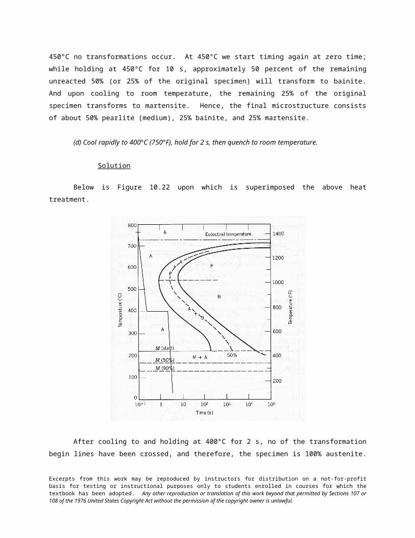
Below is Figure 10.22 upon which is superimposed the above heat treatment.
After cooling to and holding at 600°C for 4 s, approximately 50% of the specimen has transformed to
pearlite (medium). During the rapid cooling to 450°C no transformations occur. At 450°C we start timing again
at zero time; while holding at 450°C for 10 s, approximately 50 percent of the remaining unreacted 50% (or 25%
of the original specimen) will transform to bainite. And upon cooling to room temperature, the remaining 25% of
the original specimen transforms to martensite. Hence, the final microstructure consists of about 50% pearlite
(medium), 25% bainite, and 25% martensite.
(d) Cool rapidly to 400°C (750°F), hold for 2 s, then quench to room temperature.
Excerpts from this work may be reproduced by instructors for distribution on a not-for-profit basis for testing or instructional purposes only to students enrolled in courses for which the textbook has been adopted. Any other reproduction or translation of this work beyond that permitted by Sections 107 or 108 of the 1976 United States Copyright Act without the permission of the copyright owner is unlawful.
Solution
Below is Figure 10.22 upon which is superimposed the above heat treatment.
After cooling to and holding at 400°C for 2 s, no of the transformation begin lines have been crossed, and
therefore, the specimen is 100% austenite. Upon cooling rapidly to room temperature, all of the specimen
transforms to martensite, such that the final microstructure is 100% martensite.
(e) Cool rapidly to 400°C (750°F), hold for 20 s, then quench to room temperature.
Solution
Below is Figure 10.22 upon which is superimposed the above heat treatment.
Excerpts from this work may be reproduced by instructors for distribution on a not-for-profit basis for testing or instructional purposes only to students enrolled in courses for which the textbook has been adopted. Any other reproduction or translation of this work beyond that permitted by Sections 107 or 108 of the 1976 United States Copyright Act without the permission of the copyright owner is unlawful.

After cooling and holding at 400°C for 20 s, approximately 40% of the specimen has transformed to
bainite. Upon cooling to room temperature, the remaining 60% transforms to martensite. Hence, the final
microstructure consists of about 40% bainite and 60% martensite.
(f) Cool rapidly to 400°C (750°F), hold for 200 s, then quench to room temperature.
Solution
Below is Figure 10.22 upon which is superimposed the above heat treatment.
Excerpts from this work may be reproduced by instructors for distribution on a not-for-profit basis for testing or instructional purposes only to students enrolled in courses for which the textbook has been adopted. Any other reproduction or translation of this work beyond that permitted by Sections 107 or 108 of the 1976 United States Copyright Act without the permission of the copyright owner is unlawful.

After cooling and holding at 400°C for 200 s, the entire specimen has transformed to bainite. Therefore,
during the cooling to room temperature no additional transformations will occur. Hence, the final microstructure
consists of 100% bainite.
(g) Rapidly cool to 575°C (1065°F), hold for 20 s, rapidly cool to 350°C (660°F), hold for 100 s, then
quench to room temperature.
Solution
Below is Figure 10.22 upon which is superimposed the above heat treatment.
Excerpts from this work may be reproduced by instructors for distribution on a not-for-profit basis for testing or instructional purposes only to students enrolled in courses for which the textbook has been adopted. Any other reproduction or translation of this work beyond that permitted by Sections 107 or 108 of the 1976 United States Copyright Act without the permission of the copyright owner is unlawful.

After cooling and holding at 575°C for 20 s, the entire specimen has transformed to fine pearlite.
Therefore, during the second heat treatment at 350°C no additional transformations will occur. Hence, the final
microstructure consists of 100% fine pearlite.
(h) Rapidly cool to 250°C (480°F), hold for 100 s, then quench to room temperature in water. Reheat to
315°C (600°F) for 1 h and slowly cool to room temperature.
Solution
Below is Figure 10.22 upon which is superimposed the above heat treatment.
Excerpts from this work may be reproduced by instructors for distribution on a not-for-profit basis for testing or instructional purposes only to students enrolled in courses for which the textbook has been adopted. Any other reproduction or translation of this work beyond that permitted by Sections 107 or 108 of the 1976 United States Copyright Act without the permission of the copyright owner is unlawful.

After cooling and holding at 250°C for 100 s, no transformations will have occurred—at this point, the
entire specimen is still austenite. Upon rapidly cooling to room temperature in water, the specimen will
completely transform to martensite. The second heat treatment (at 315°C for 1 h)—not shown on the above plot
—will transform the material to tempered martensite. Hence, the final microstructure is 100% tempered
martensite.
Excerpts from this work may be reproduced by instructors for distribution on a not-for-profit basis for testing or instructional purposes only to students enrolled in courses for which the textbook has been adopted. Any other reproduction or translation of this work beyond that permitted by Sections 107 or 108 of the 1976 United States Copyright Act without the permission of the copyright owner is unlawful.

10.19 Make a copy of the isothermal transformation diagram for an iron–carbon alloy of eutectoid
composition (Figure 10.22) and then sketch and label time–temperature paths on this diagram to produce the
following microstructures:
(a) 100% fine pearlite
(b) 100% tempered martensite
(c) 50% coarse pearlite, 25% bainite, and 25% martensite
Solution
Below is shown the isothermal transformation diagram for a eutectoid iron-carbon alloy, with time-
temperature paths that will yield (a) 100% fine pearlite; (b) 100% tempered martensite; and (c) 50% coarse
pearlite, 25% bainite, and 25% martensite.
Excerpts from this work may be reproduced by instructors for distribution on a not-for-profit basis for testing or instructional purposes only to students enrolled in courses for which the textbook has been adopted. Any other reproduction or translation of this work beyond that permitted by Sections 107 or 108 of the 1976 United States Copyright Act without the permission of the copyright owner is unlawful.

10.20 Using the isothermal transformation diagram for a 0.45 wt% C steel alloy (Figure 10.39),
determine the final microstructure (in terms of just the microconstituents present) of a small specimen that has
been subjected to the following time-temperature treatments. In each case assume that the specimen begins at
845C (1550F), and that it has been held at this temperature long enough to have achieved a complete and
homogeneous austenitic structure.
(a) Rapidly cool to 250C (480F), hold for 103 s, then quench to room temperature.
Solution
Below is Figure 10.39 upon which is superimposed the above heat treatment.
While rapidly cooling to 250°C about 80% of the specimen transforms to martensite; during the 1000 s
isothermal treatment at 250°C no additional transformations occur. During the final cooling to room temperature,
the untransformed austenite also transforms to martensite. Hence, the final microstructure consists of 100%
martensite.
(b) Rapidly cool to 700C (1290F), hold for 30 s, then quench to room temperature.
Solution
Below is Figure 10.39 upon which is superimposed the above heat treatment.
Excerpts from this work may be reproduced by instructors for distribution on a not-for-profit basis for testing or instructional purposes only to students enrolled in courses for which the textbook has been adopted. Any other reproduction or translation of this work beyond that permitted by Sections 107 or 108 of the 1976 United States Copyright Act without the permission of the copyright owner is unlawful.

After cooling to and holding at 700°C for 30 s, a portion of specimen has transformed to proeutectoid
ferrite. While cooling to room temperature, the remainder of the specimen transforms to martensite. Hence, the
final microstructure consists proeutectoid ferrite and martensite.
(c) Rapidly cool to 400C (750F), hold for 500 s, then quench to room temperature.
Solution
Below is Figure 10.39 upon which is superimposed the above heat treatment.
Excerpts from this work may be reproduced by instructors for distribution on a not-for-profit basis for testing or instructional purposes only to students enrolled in courses for which the textbook has been adopted. Any other reproduction or translation of this work beyond that permitted by Sections 107 or 108 of the 1976 United States Copyright Act without the permission of the copyright owner is unlawful.

After cooling to and holding at 400°C for 500 s, all of the specimen has transformed to bainite. Hence,
the final microstructure consists of 100% bainite.
(d) Rapidly cool to 700C (1290F), hold at this temperature for 105 s, then quench to room temperature.
Solution
Below is Figure 10.39 upon which is superimposed the above heat treatment.
Excerpts from this work may be reproduced by instructors for distribution on a not-for-profit basis for testing or instructional purposes only to students enrolled in courses for which the textbook has been adopted. Any other reproduction or translation of this work beyond that permitted by Sections 107 or 108 of the 1976 United States Copyright Act without the permission of the copyright owner is unlawful.

After cooling to and while holding at 700°C the specimen first transforms to proeutectoid ferrite and
coarse pearlite. Continued heat treating at 700°C for 105 s results in a further transformation into spheroidite.
Hence, the final microstructure consists of 100% spheroidite.
(e) Rapidly cool to 650C (1200F), hold at this temperature for 3 s, rapidly cool to 400C (750F), hold
for 10 s, then quench to room temperature.
Solution
Below is Figure 10.39 upon which is superimposed the above heat treatment.
Excerpts from this work may be reproduced by instructors for distribution on a not-for-profit basis for testing or instructional purposes only to students enrolled in courses for which the textbook has been adopted. Any other reproduction or translation of this work beyond that permitted by Sections 107 or 108 of the 1976 United States Copyright Act without the permission of the copyright owner is unlawful.

After cooling to and holding at 650°C for 3 s, some of the specimen first transformers to proeutectoid
ferrite and then to pearlite (medium). During the second stage of the heat treatment at 400°C, some (but not all)
of the remaining unreacted austenite transforms to bainite. As a result of the final quenching, all of the remaining
austenite transforms to martensite. Hence, the final microstructure consists of ferrite, pearlite (medium), bainite,
and martensite.
(f) Rapidly cool to 450C (840F), hold for 10 s, then quench to room temperature.
Solution
Below is Figure 10.39 upon which is superimposed the above heat treatment.
Excerpts from this work may be reproduced by instructors for distribution on a not-for-profit basis for testing or instructional purposes only to students enrolled in courses for which the textbook has been adopted. Any other reproduction or translation of this work beyond that permitted by Sections 107 or 108 of the 1976 United States Copyright Act without the permission of the copyright owner is unlawful.

After cooling to and holding at 450°C for 10 s, a portion of the specimen first transformers to bainite.
During the quenching to room temperature, the remainder of the specimen transforms to martensite. Hence, the
final microstructure consists of bainite and martensite.
(g) Rapidly cool to 625C (1155F), hold for 1 s, then quench to room temperature.
Solution
Below is Figure 10.39 upon which is superimposed the above heat treatment.
Excerpts from this work may be reproduced by instructors for distribution on a not-for-profit basis for testing or instructional purposes only to students enrolled in courses for which the textbook has been adopted. Any other reproduction or translation of this work beyond that permitted by Sections 107 or 108 of the 1976 United States Copyright Act without the permission of the copyright owner is unlawful.

After cooling to and holding at 625°C for 1 s, a portion of the specimen first transformers to proeutectoid
ferrite and pearlite. During the quenching to room temperature, the remainder of the specimen transforms to
martensite. Hence, the final microstructure consists of ferrite, pearlite, and martensite.
(h) Rapidly cool to 625C (1155F), hold at this temperature for 10 s, rapidly cool to 400C (750F), hold
at this temperature for 5 s, then quench to room temperature.
Solution
Below is Figure 10.39 upon which is superimposed the above heat treatment.
Excerpts from this work may be reproduced by instructors for distribution on a not-for-profit basis for testing or instructional purposes only to students enrolled in courses for which the textbook has been adopted. Any other reproduction or translation of this work beyond that permitted by Sections 107 or 108 of the 1976 United States Copyright Act without the permission of the copyright owner is unlawful.

After cooling to and holding at 625°C for 10 s, all of the specimen transformers to proeutectoid ferrite
and pearlite. During the second part of the heat treatment at 400°C no additional transformation will occur.
Hence, the final microstructure consists of ferrite and pearlite.
Excerpts from this work may be reproduced by instructors for distribution on a not-for-profit basis for testing or instructional purposes only to students enrolled in courses for which the textbook has been adopted. Any other reproduction or translation of this work beyond that permitted by Sections 107 or 108 of the 1976 United States Copyright Act without the permission of the copyright owner is unlawful.

10.21 For parts (a), (c), (d), (f), and (h) of Problem 10.20, determine the approximate percentages of the
microconstituents that form.
Solution
(a) From Problem 10.20(a) the microstructure consists of 100% martensite.
(c) From Problem 10.20(c) the microstructure consists of 100% bainite.
(d) From Problem 10.20(d) the microstructure consists of 100% spheroidite.
(f) Figure 10.39 onto which the heat treatment for Problem 10.20(f) has been constructed is shown
below.
From this diagram, for the isothermal heat treatment at 450C, the horizontal line constructed at this temperature
and that ends at the 10 s point spans approximately 70% of the distance between the bainite reaction start and
reaction completion curves. Therefore, the final microstructure consists of about 70% bainite and 30% martensite
(the martensite forms while cooling to room temperature after 10 s at 450C).
(h) Figure 10.39 onto which the heat treatment for Problem 10.20(h) has been constructed is shown
below.
Excerpts from this work may be reproduced by instructors for distribution on a not-for-profit basis for testing or instructional purposes only to students enrolled in courses for which the textbook has been adopted. Any other reproduction or translation of this work beyond that permitted by Sections 107 or 108 of the 1976 United States Copyright Act without the permission of the copyright owner is unlawful.

After holding for 10 s at 625C, the specimen has completely transformed to proeutectoid ferrite and fine pearlite;
no further reaction will occur at 400C. Therefore, we can calculate the mass fractions using the appropriate lever
rule expressions, Equations 9.20 and 9.21, as follows:
€
Wp =C0
’ − 0.022
0.74=
0.45 − 0.022
0.74= 0.58 or 58%
€
W' =0.76 − C0
’
0.74=
0.76 − 0.45
0.74= 0.42 or 42%
Excerpts from this work may be reproduced by instructors for distribution on a not-for-profit basis for testing or instructional purposes only to students enrolled in courses for which the textbook has been adopted. Any other reproduction or translation of this work beyond that permitted by Sections 107 or 108 of the 1976 United States Copyright Act without the permission of the copyright owner is unlawful.

10.22 Make a copy of the isothermal transformation diagram for a 0.45 wt% C iron-carbon alloy
(Figure 10.39), and then sketch and label on this diagram the time-temperature paths to produce the following
microstructures:
(a) 42% proeutectoid ferrite and 58% coarse pearlite
(b) 50% fine pearlite and 50% bainite
(c) 100% martensite
(d) 50% martensite and 50% austenite
Solution
Below is shown an isothermal transformation diagram for a 0.45 wt% C iron-carbon alloy, with time-
temperature paths that will produce (a) 42% proeutectoid ferrite and 58% coarse pearlite; (b) 50% fine pearlite
and 50% bainite; (c) 100% martensite; and (d) 50% martensite and 50% austenite.
Excerpts from this work may be reproduced by instructors for distribution on a not-for-profit basis for testing or instructional purposes only to students enrolled in courses for which the textbook has been adopted. Any other reproduction or translation of this work beyond that permitted by Sections 107 or 108 of the 1976 United States Copyright Act without the permission of the copyright owner is unlawful.

Continuous Cooling Transformation Diagrams
10.23 Name the microstructural products of eutectoid iron–carbon alloy (0.76 wt% C) specimens that
are first completely transformed to austenite, then cooled to room temperature at the following rates:
(a) 200°C/s,
(b) 100°C/s, and
(c) 20°C/s.
Solution
We are called upon to name the microstructural products that form for specimens of an iron-carbon alloy
of eutectoid composition that are continuously cooled to room temperature at a variety of rates. Figure 10.27 is
used in these determinations.
(a) At a rate of 200°C/s, only martensite forms.
(b) At a rate of 100°C/s, both martensite and pearlite form.
(c) At a rate of 20°C/s, only fine pearlite forms.
Excerpts from this work may be reproduced by instructors for distribution on a not-for-profit basis for testing or instructional purposes only to students enrolled in courses for which the textbook has been adopted. Any other reproduction or translation of this work beyond that permitted by Sections 107 or 108 of the 1976 United States Copyright Act without the permission of the copyright owner is unlawful.

10.24 Figure 10.40 shows the continuous cooling transformation diagram for a 1.13 wt% C iron-carbon
alloy. Make a copy of this figure and then sketch and label continuous cooling curves to yield the following
microstructures:
(a) Fine pearlite and proeutectoid cementite
(b) Martensite
(c) Martensite and proeutectoid cementite
(d) Coarse pearlite and proeutectoid cementite
(e) Martensite, fine pearlite, and proeutectoid cementite
Solution
Below is shown a continuous cooling transformation diagram for a 1.13 wt% C iron-carbon alloy, with
continuous cooling paths that will produce (a) fine pearlite and proeutectoid cementite; (b) martensite; (c)
martensite and proeutectoid cementite; (d) coarse pearlite and proeutectoid cementite; and (e) martensite, fine
pearlite, and proeutectoid cementite.
Excerpts from this work may be reproduced by instructors for distribution on a not-for-profit basis for testing or instructional purposes only to students enrolled in courses for which the textbook has been adopted. Any other reproduction or translation of this work beyond that permitted by Sections 107 or 108 of the 1976 United States Copyright Act without the permission of the copyright owner is unlawful.

10.25 Cite two important differences between continuous cooling transformation diagrams for plain
carbon and alloy steels.
Solution
Two important differences between continuous cooling transformation diagrams for plain carbon and
alloy steels are: (1) for an alloy steel, a bainite nose will be present, which nose will be absent for plain carbon
alloys; and (2) the pearlite-proeutectoid noses for plain carbon steel alloys are positioned at shorter times than for
the alloy steels.
Excerpts from this work may be reproduced by instructors for distribution on a not-for-profit basis for testing or instructional purposes only to students enrolled in courses for which the textbook has been adopted. Any other reproduction or translation of this work beyond that permitted by Sections 107 or 108 of the 1976 United States Copyright Act without the permission of the copyright owner is unlawful.

10.26 Briefly explain why there is no bainite transformation region on the continuous cooling
transformation diagram for an iron–carbon alloy of eutectoid composition.
Solution
There is no bainite transformation region on the continuous cooling transformation diagram for an iron-
carbon alloy of eutectoid composition (Figure 10.25) because by the time a cooling curve has passed into the
bainite region, the entirety of the alloy specimen will have transformed to pearlite.
Excerpts from this work may be reproduced by instructors for distribution on a not-for-profit basis for testing or instructional purposes only to students enrolled in courses for which the textbook has been adopted. Any other reproduction or translation of this work beyond that permitted by Sections 107 or 108 of the 1976 United States Copyright Act without the permission of the copyright owner is unlawful.

10.27 Name the microstructural products of 4340 alloy steel specimens that are first completely
transformed to austenite, then cooled to room temperature at the following rates:
(a) 10°C/s,
(b) 1°C/s,
(c) 0.1°C/s, and
(d) 0.01°C/s.
Solution
This problem asks for the microstructural products that form when specimens of a 4340 steel are
continuously cooled to room temperature at several rates. Figure 10.28 is used for these determinations.
(a) At a cooling rate of 10C/s, only martensite forms.
(b) At a cooling rate of 1C/s, both martensite and bainite form.
(c) At a cooling rate of 0.1C/s, martensite, proeutectoid ferrite, and bainite form.
(d) At a cooling rate of 0.01C/s, martensite, proeutectoid ferrite, pearlite, and bainite form.
Excerpts from this work may be reproduced by instructors for distribution on a not-for-profit basis for testing or instructional purposes only to students enrolled in courses for which the textbook has been adopted. Any other reproduction or translation of this work beyond that permitted by Sections 107 or 108 of the 1976 United States Copyright Act without the permission of the copyright owner is unlawful.

10.28 Briefly describe the simplest continuous cooling heat treatment procedure that would be used in
converting a 4340 steel from one microstructure to another.
(a) (Martensite + bainite) to (ferrite + pearlite)
(b) (Martensite + bainite) to spheroidite
(c) (Martensite + bainite) to (martensite + bainite + ferrite)
Solution
This problem asks that we briefly describe the simplest continuous cooling heat treatment procedure that
would be used in converting a 4340 steel from one microstructure to another. Solutions to this problem require
the use of Figure 10.28.
(a) In order to convert from (martensite + bainite) to (ferrite + pearlite) it is necessary to heat above about
720C, allow complete austenitization, then cool to room temperature at a rate slower than 0.006 C/s.
(b) To convert from (martensite + bainite) to spheroidite the alloy must be heated to about 700 C for
several hours.
(c) In order to convert from (martensite + bainite) to (martensite + bainite + ferrite) it is necessary to heat
to above about 720C, allow complete austenitization, then cool to room temperature at a rate between 0.3 C/s and
0.02C/s.
Excerpts from this work may be reproduced by instructors for distribution on a not-for-profit basis for testing or instructional purposes only to students enrolled in courses for which the textbook has been adopted. Any other reproduction or translation of this work beyond that permitted by Sections 107 or 108 of the 1976 United States Copyright Act without the permission of the copyright owner is unlawful.

10.29 On the basis of diffusion considerations, explain why fine pearlite forms for the moderate cooling
of austenite through the eutectoid temperature, whereas coarse pearlite is the product for relatively slow cooling
rates.
Solution
For moderately rapid cooling, the time allowed for carbon diffusion is not as great as for slower cooling
rates. Therefore, the diffusion distance is shorter, and thinner layers of ferrite and cementite form (i.e., fine
pearlite forms).
Excerpts from this work may be reproduced by instructors for distribution on a not-for-profit basis for testing or instructional purposes only to students enrolled in courses for which the textbook has been adopted. Any other reproduction or translation of this work beyond that permitted by Sections 107 or 108 of the 1976 United States Copyright Act without the permission of the copyright owner is unlawful.

Mechanical Behavior of Iron-Carbon Alloys
Tempered Martensite
10.30 Briefly explain why fine pearlite is harder and stronger than coarse pearlite, which in turn is
harder and stronger than spheroidite.
Solution
The hardness and strength of iron-carbon alloys that have microstructures consisting of -ferrite and
cementite phases depend on the boundary area between the two phases. The greater this area, the harder and
stronger the alloy inasmuch as (1) these boundaries impede the motion of dislocations, and (2) the cementite phase
restricts the deformation of the ferrite phase in regions adjacent to the phase boundaries. Fine pearlite is harder
and stronger than coarse pearlite because the alternating ferrite-cementite layers are thinner for fine, and therefore,
there is more phase boundary area. The phase boundary area between the sphere-like cementite particles and the
ferrite matrix is less in spheroidite than for the alternating layered microstructure found in coarse pearlite.
Excerpts from this work may be reproduced by instructors for distribution on a not-for-profit basis for testing or instructional purposes only to students enrolled in courses for which the textbook has been adopted. Any other reproduction or translation of this work beyond that permitted by Sections 107 or 108 of the 1976 United States Copyright Act without the permission of the copyright owner is unlawful.

10.31 Cite two reasons why martensite is so hard and brittle.
Solution
Two reasons why martensite is so hard and brittle are: (1) there are relatively few operable slip systems
for the body-centered tetragonal crystal structure, and (2) virtually all of the carbon is in solid solution, which
produces a solid-solution hardening effect.
Excerpts from this work may be reproduced by instructors for distribution on a not-for-profit basis for testing or instructional purposes only to students enrolled in courses for which the textbook has been adopted. Any other reproduction or translation of this work beyond that permitted by Sections 107 or 108 of the 1976 United States Copyright Act without the permission of the copyright owner is unlawful.
10.32 Rank the following iron–carbon alloys and associated microstructures from the highest to the
lowest tensile strength:
(a) 0.25 wt%C with spheroidite,
(b) 0.25 wt%C with coarse pearlite,
(c) 0.60 wt%C with fine pearlite, and
(d) 0.60 wt%C with coarse pearlite.
Justify this ranking.
Solution
This problem asks us to rank four iron-carbon alloys of specified composition and microstructure
according to hardness. This ranking is as follows:
0.60 wt% C, fine pearlite
0.60 wt% C, coarse pearlite
0.25 wt% C, coarse pearlite
0.25 wt% C, spheroidite
The 0.25 wt% C, coarse pearlite is stronger than the 0.25 wt% C, spheroidite since coarse pearlite is
stronger than spheroidite; the composition of the alloys is the same. The 0.60 wt% C, coarse pearlite is stronger
than the 0.25 wt% C, coarse pearlite, since increasing the carbon content increases the strength. Finally, the 0.60
wt% C, fine pearlite is stronger than the 0.60 wt% C, coarse pearlite inasmuch as the strength of fine pearlite is
greater than coarse pearlite because of the many more ferrite-cementite phase boundaries in fine pearlite.
Excerpts from this work may be reproduced by instructors for distribution on a not-for-profit basis for testing or instructional purposes only to students enrolled in courses for which the textbook has been adopted. Any other reproduction or translation of this work beyond that permitted by Sections 107 or 108 of the 1976 United States Copyright Act without the permission of the copyright owner is unlawful.

10.33 Briefly explain why the hardness of tempered martensite diminishes with tempering time (at
constant temperature) and with increasing temperature (at constant tempering time).
Solution
This question asks for an explanation as to why the hardness of tempered martensite diminishes with
tempering time (at constant temperature) and with increasing temperature (at constant tempering time). The
hardness of tempered martensite depends on the ferrite-cementite phase boundary area; since these phase
boundaries are barriers to dislocation motion, the greater the area the harder the alloy. The microstructure of
tempered martensite consists of small sphere-like particles of cementite embedded within a ferrite matrix. As the
size of the cementite particles increases, the phase boundary area diminishes, and the alloy becomes softer.
Therefore, with increasing tempering time, the cementite particles grow, the phase boundary area decreases, and
the hardness diminishes. As the tempering temperature is increased, the rate of cementite particle growth also
increases, and the alloy softens, again, because of the decrease in phase boundary area.
Excerpts from this work may be reproduced by instructors for distribution on a not-for-profit basis for testing or instructional purposes only to students enrolled in courses for which the textbook has been adopted. Any other reproduction or translation of this work beyond that permitted by Sections 107 or 108 of the 1976 United States Copyright Act without the permission of the copyright owner is unlawful.

10.34 Briefly describe the simplest heat treatment procedure that would be used in converting a 0.76 wt
% C steel from one microstructure to the other, as follows:
(a) Spheroidite to tempered martensite
(b) Tempered martensite to pearlite
(c) Bainite to martensite
(d) Martensite to pearlite
(e) Pearlite to tempered martensite
(f) Tempered martensite to pearlite
(g) Bainite to tempered martensite
(h) Tempered martensite to spheroidite
Solution
In this problem we are asked to describe the simplest heat treatment that would be required to convert a
eutectoid steel from one microstructure to another. Figure 10.27 is used to solve the several parts of this problem.
(a) For spheroidite to tempered martensite, austenitize at a temperature of about 760 C, quench to room
temperature at a rate greater than about 140C/s, then isothermally heat at a temperature between 250 and 650C.
(b) For tempered martensite to pearlite, austenitize at a temperature of about 760 C, then cool to room
temperature at a rate less than about 35C/s.
(c) For bainite to martensite, first austenitize at a temperature of about 760C, then quench to room
temperature at a rate greater than about 140C/s.
(d) For martensite to pearlite, first austenitize at a temperature of about 760 C, then cool to room
temperature at a rate less than about 35C/s.
(e) For pearlite to tempered martensite, first austenitize at a temperature of about 760 C, then rapidly
quench to room temperature at a rate greater than about 140 C/s, then isothermally heat treat (temper) at a
temperature between 250 and 650C.
(f) For tempered martensite to pearlite, first austenitize at a temperature of about 760 C, then cool to
room temperature at a rate less than about 35C/s.
(g) For bainite to tempered martensite, first austenitize at a temperature of about 760 C, then rapidly
quench to room temperature at a rate greater than about 140 C/s, then isothermally heat treat (temper) at a
temperature between 250 and 650C.
(h) For tempered martensite to spheroidite simply heat at about 700C for approximately 20 h.
Excerpts from this work may be reproduced by instructors for distribution on a not-for-profit basis for testing or instructional purposes only to students enrolled in courses for which the textbook has been adopted. Any other reproduction or translation of this work beyond that permitted by Sections 107 or 108 of the 1976 United States Copyright Act without the permission of the copyright owner is unlawful.

10.35 (a) Briefly describe the microstructural difference between spheroidite and tempered martensite.
(b) Explain why tempered martensite is much harder and stronger.
Solution
(a) Both tempered martensite and spheroidite have sphere-like cementite particles within a ferrite matrix;
however, these particles are much larger for spheroidite.
(b) Tempered martensite is harder and stronger inasmuch as there is much more ferrite-cementite phase
boundary area for the smaller particles; thus, there is greater reinforcement of the ferrite phase, and more phase
boundary barriers to dislocation motion.
Excerpts from this work may be reproduced by instructors for distribution on a not-for-profit basis for testing or instructional purposes only to students enrolled in courses for which the textbook has been adopted. Any other reproduction or translation of this work beyond that permitted by Sections 107 or 108 of the 1976 United States Copyright Act without the permission of the copyright owner is unlawful.

10.36 Estimate the Rockwell hardnesses for specimens of an iron–carbon alloy of eutectoid composition
that have been subjected to the heat treatments described in parts (b), (d), (f), (g), and (h) of Problem 10 .18.
Solution
This problem asks for estimates of Rockwell hardness values for specimens of an iron-carbon alloy of
eutectoid composition that have been subjected to some of the heat treatments described in Problem 10.18.
(b) The microstructural product of this heat treatment is 100% spheroidite. According to Figure 10.30a,
the hardness of a 0.76 wt% C alloy with spheroidite is about 87 HRB.
(d) The microstructural product of this heat treatment is 100% martensite. According to Figure 10.32,
the hardness of a 0.76 wt% C alloy consisting of martensite is about 64 HRC.
(f) The microstructural product of this heat treatment is 100% bainite. From Figure 10.31, the hardness
of a 0.76 wt% C alloy consisting of bainite is about 385 HB. And, conversion from Brinell to Rockwell hardness
using Figure 6.18 leads to a hardness of 36 HRC.
(g) The microstructural product of this heat treatment is 100% fine pearlite. According to Figure 10.30a,
the hardness of a 0.76 wt% C alloy consisting of fine pearlite is about 27 HRC.
(h) The microstructural product of this heat treatment is 100% tempered martensite. According to Figure
10.35, the hardness of a water-quenched eutectoid alloy that was tempered at 315C for one hour is about 57 HRC.
Excerpts from this work may be reproduced by instructors for distribution on a not-for-profit basis for testing or instructional purposes only to students enrolled in courses for which the textbook has been adopted. Any other reproduction or translation of this work beyond that permitted by Sections 107 or 108 of the 1976 United States Copyright Act without the permission of the copyright owner is unlawful.

10.37 Estimate the Brinell hardnesses for specimens of a 0.45 wt% C iron-carbon alloy that have been
subjected to the heat treatments described in parts (a), (d), and (h) of Problem 10.20.
Solution
This problem asks for estimates of Brinell hardness values for specimens of an iron-carbon alloy of
composition 0.45 wt% C that have been subjected to some of the heat treatments described in Problem 10.20.
(a) The microstructural product of this heat treatment is 100% martensite. According to Figure 10.32, the
hardness of a 0.45 wt% C alloy consisting of martensite is about 630 HB.
(d) The microstructural product of this heat treatment is 100% spheroidite. According to Figure 10.30 a
the hardness of a 0.45 wt% C alloy with spheroidite is about 150 HB.
(h) The microstructural product of this heat treatment is proeutectoid ferrite and fine pearlite. According
to Figure 10.30a, the hardness of a 0.45 wt% C alloy consisting of fine pearlite is about 200 HB.
Excerpts from this work may be reproduced by instructors for distribution on a not-for-profit basis for testing or instructional purposes only to students enrolled in courses for which the textbook has been adopted. Any other reproduction or translation of this work beyond that permitted by Sections 107 or 108 of the 1976 United States Copyright Act without the permission of the copyright owner is unlawful.

10.38 Determine the approximate tensile strengths for specimens of a eutectoid iron–carbon alloy that
have experienced the heat treatments described in parts (a) and (c) of Problem 10.23.
Solution
This problem asks for estimates of tensile strength values for specimens of an iron-carbon alloy of
eutectoid composition that have been subjected to some of the heat treatments described in Problem 10.23.
(a) The microstructural product of this heat treatment is 100% martensite. According to Figure 10.32, the
hardness of a 0.76 wt% C alloy is about 690 HB. For steel alloys, hardness and tensile strength are related through
Equation 6.20a, and therefore
€
TS (MPa) = 3.45 × HB = (3.45)(690 HB) = 2380 MPa (345,000 psi)
(c) The microstructural product of this heat treatment is 100% fine pearlite. According to Figure 10.30 a,
the hardness of a 0.76 wt% C alloy consisting of fine pearlite is about 265 HB. Therefore, the tensile strength is
€
TS (MPa) = 3.45 × HB = (3.45)(265 HB) = 915 MPa (132,500 psi)
Excerpts from this work may be reproduced by instructors for distribution on a not-for-profit basis for testing or instructional purposes only to students enrolled in courses for which the textbook has been adopted. Any other reproduction or translation of this work beyond that permitted by Sections 107 or 108 of the 1976 United States Copyright Act without the permission of the copyright owner is unlawful.

10.39 For a eutectoid steel, describe isothermal heat treatments that would be required to yield
specimens having the following Rockwell hardnesses:
(a) 93 HRB,
(b) 40 HRC, and
(c) 27 HRC.
Solution
For this problem we are asked to describe isothermal heat treatments required to yield specimens having
several Brinell hardnesses.
(a) From Figure 10.30a, in order for a 0.76 wt% C alloy to have a Rockwell hardness of 93 HRB, the
microstructure must be coarse pearlite. Thus, utilizing the isothermal transformation diagram for this alloy,
Figure 10.22, we must rapidly cool to a temperature at which coarse pearlite forms (i.e., to about 675 C), allow the
specimen to isothermally and completely transform to coarse pearlite. At this temperature an isothermal heat
treatment for at least 200 s is required.
(b) This portion of the problem asks for a hardness of 40 HRC the microstructure could consist of either
(1) about 75% fine pearlite and 25% martensite (Figure 10.32), or (2) tempered martensite (Figure 10.35).
For case (1), after austenitizing, rapidly cool to about 580 C (Figure 10.22), hold at this temperature for
about 4 s (to obtain 75% fine pearlite), and then rapidly quench to room temperature.
For case (2), after austenitizing, rapidly cool to room temperature in order to achieve 100% martensite.
Then temper this martensite for about 2000 s at 535C (Figure 10.35).
(c) From Figure 10.30a, in order for a 0.76 wt% C alloy to have a Rockwell hardness of 27 HRC, the
microstructure must be fine pearlite. Thus, utilizing the isothermal transformation diagram for this alloy, Figure
10.22, we must rapidly cool to a temperature at which fine pearlite forms (i.e., at about 580 C), allow the
specimen to isothermally and completely transform to fine pearlite. At this temperature an isothermal heat
treatment for at least 7 s is required.
Excerpts from this work may be reproduced by instructors for distribution on a not-for-profit basis for testing or instructional purposes only to students enrolled in courses for which the textbook has been adopted. Any other reproduction or translation of this work beyond that permitted by Sections 107 or 108 of the 1976 United States Copyright Act without the permission of the copyright owner is unlawful.

DESIGN PROBLEMS
Continuous Cooling Transformation Diagrams
Mechanical Behavior of Iron-Carbon Alloys
10.D1 Is it possible to produce an iron-carbon alloy of eutectoid composition that has a minimum
hardness of 90 HRB and a minimum ductility of 35%RA? If so, describe the continuous cooling heat treatment to
which the alloy would be subjected to achieve these properties. If it is not possible, explain why.
Solution
This problem inquires as to the possibility of producing an iron-carbon alloy of eutectoid composition
that has a minimum hardness of 90 HRB and a minimum ductility of 35%RA. If the alloy is possible, then the
continuous cooling heat treatment is to be stipulated.
According to Figures 10.30a and b, the following is a tabulation of Rockwell B hardnesses and percents
area reduction for fine and coarse pearlites and spheroidite for a 0.76 wt% C alloy.
Microstructure HRB %RA
Fine pearlite > 100 20
Coarse pearlite 93 28
Spheroidite 88 67
Therefore, none of the microstructures meets both of these criteria. Both fine and coarse pearlites are
hard enough, but lack the required ductility. Spheroidite is sufficiently ductile, but does not meet the hardness
criterion.
Excerpts from this work may be reproduced by instructors for distribution on a not-for-profit basis for testing or instructional purposes only to students enrolled in courses for which the textbook has been adopted. Any other reproduction or translation of this work beyond that permitted by Sections 107 or 108 of the 1976 United States Copyright Act without the permission of the copyright owner is unlawful.

10.D2 Is it possible to produce an iron-carbon alloy that has a minimum tensile strength of 690 MPa
(100,000 psi) and a minimum ductility of 40%RA? If so, what will be its composition and microstructure (coarse
and fine pearlites and spheroidite are alternatives)? If this is not possible, explain why.
Solution
This problem asks if it is possible to produce an iron-carbon alloy that has a minimum tensile strength of
690 MPa (100,000 psi) and a minimum ductility of 40%RA. If such an alloy is possible, its composition and
microstructure are to be stipulated.
From Equation 6.20a, this tensile strength corresponds to a Brinell hardness of
€
HB =TS (MPa)
3.45=
690 MPa
3.45= 200
According to Figures 10.30a and b, the following is a tabulation of the composition ranges for fine and coarse
pearlites and spheroidite that meet the stipulated criteria.
Compositions for Compositions forMicrostructure HB 200 %RA 40%
Fine pearlite > 0.45 %C < 0.47 %C
Coarse pearlite > 0.7 %C < 0.54 %C
Spheroidite not possible 0-1.0 %C
Therefore, only fine pearlite has a composition range overlap for both of the hardness and ductility restrictions;
the fine pearlite would necessarily have to have a carbon content between 0.45 and 0.47 wt% C.
Excerpts from this work may be reproduced by instructors for distribution on a not-for-profit basis for testing or instructional purposes only to students enrolled in courses for which the textbook has been adopted. Any other reproduction or translation of this work beyond that permitted by Sections 107 or 108 of the 1976 United States Copyright Act without the permission of the copyright owner is unlawful.

10.D3 It is desired to produce an iron-carbon alloy that has a minimum hardness of 175 HB and a
minimum ductility of 52%RA. Is such an alloy possible? If so, what will be its composition and microstructure
(coarse and fine pearlites and spheroidite are alternatives)? If this is not possible, explain why.
Solution
This problem inquires as to the possibility of producing a iron-carbon alloy having a minimum hardness
of 175 HB and a minimum ductility of 52%RA. The composition and microstructure are to be specified; possible
microstructures include fine and coarse pearlites and spheroidite.
To solve this problem, we must consult Figures 10.30a and b. The following is a tabulation of the
composition ranges for fine and coarse pearlites and spheroidite that meet the stipulated criteria.
Compositions for Compositions forMicrostructure HB 175 %RA 52%
Fine pearlite > 0.36 %C < 0.33 %C
Coarse pearlite > 0.43 %C < 0.40 %C
Spheroidite > 0.70 <0-1.0 %C
Thus, only spheroidite has a composition overlap for both of hardness and ductility restrictions; the spheroidite
would necessarily have to have a carbon content greater than 0.70 wt% C.
Excerpts from this work may be reproduced by instructors for distribution on a not-for-profit basis for testing or instructional purposes only to students enrolled in courses for which the textbook has been adopted. Any other reproduction or translation of this work beyond that permitted by Sections 107 or 108 of the 1976 United States Copyright Act without the permission of the copyright owner is unlawful.

Tempered Martensite
10.D4 (a) For a 1080 steel that has been water quenched, estimate the tempering time at 425°C (800°F)
to achieve a hardness of 50 HRC.
(b) What will be the tempering time at 315°C (600°F) necessary to attain the same hardness?
Solution
This problem asks us to consider the tempering of a water-quenched 1080 steel to achieve a hardness of
50 HRC. It is necessary to use Figure 10.35.
(a) The time necessary at 425C is about 500 s.
(b) At 315C, the time required (by extrapolation) is approximately 4 106 s (about 50 days).
Excerpts from this work may be reproduced by instructors for distribution on a not-for-profit basis for testing or instructional purposes only to students enrolled in courses for which the textbook has been adopted. Any other reproduction or translation of this work beyond that permitted by Sections 107 or 108 of the 1976 United States Copyright Act without the permission of the copyright owner is unlawful.

10.D5 An alloy steel (4340) is to be used in an application requiring a minimum tensile strength of 1380
MPa (200,000 psi) and a minimum ductility of 43%RA. Oil quenching followed by tempering is to be used. Briefly
describe the tempering heat treatment.
Solution
We are to consider the tempering of an oil-quenched 4340 steel. From Figure 10.34, for a minimum
tensile strength of 1380 MPa (200,000 psi) a tempering temperature of less than 450 C (840F) is required. Also,
for a minimum ductility of 43%RA, tempering must be carried out at a temperature greater than about 400 C
(750F). Therefore, tempering must occur at between 400 and 450C (750 and 840F) for 1 h.
Excerpts from this work may be reproduced by instructors for distribution on a not-for-profit basis for testing or instructional purposes only to students enrolled in courses for which the textbook has been adopted. Any other reproduction or translation of this work beyond that permitted by Sections 107 or 108 of the 1976 United States Copyright Act without the permission of the copyright owner is unlawful.

10.D6 Is it possible to produce an oil-quenched and tempered 4340 steel that has a minimum yield
strength of 1400 MPa (203,000 psi) and a ductility of at least 42%RA? If this is possible, describe the tempering
heat treatment. If it is not possible, explain why.
Solution
This problem asks if it is possible to produce an oil-quenched and tempered 4340 steel that has a
minimum yield strength of 1400 MPa (203,000 psi) and a minimum ductility of 42%RA, and, if possible, to
describe the tempering heat treatment. In Figure 10.34 is shown the tempering characteristics of this alloy.
According to this figure, in order to achieve a minimum yield strength of 1400 MPa a tempering temperature of
less that about 410C is required. On the other hand, tempering must be carried out at greater than about 360 C
for a minimum ductility of 42%RA. Therefore, an oil-quenched and tempered 4340 alloy possessing these
characteristics is possible; tempering would be carried out at between 360C and 410C for 1 h.
Excerpts from this work may be reproduced by instructors for distribution on a not-for-profit basis for testing or instructional purposes only to students enrolled in courses for which the textbook has been adopted. Any other reproduction or translation of this work beyond that permitted by Sections 107 or 108 of the 1976 United States Copyright Act without the permission of the copyright owner is unlawful.