Embed Size (px)
Citation preview

Ch.12 Norton theorem & maximum power transfer theorem
Page 1
3-NORTON’S THEOREM Any two-terminal linear bilateral dc network can be
replaced by an equivalent circuit consisting of a current source and a parallel resistor, as
shown in Fig. (a)
Fig.(a)
Ch.12 Norton theorem & maximum power transfer theorem
Page 2
The Norton and Thévenin equivalent circuits can also be found from each other by using
the source transformation Fig. (b)
Fig.(b) Converting between Thévenin and Norton equivalent circuits.
EXAMPLE (1) Find the Norton equivalent circuit for the network in the shaded area of
Fig. (1)
fig(1)
Note
Ch.12 Norton theorem & maximum power transfer theorem
Page 3
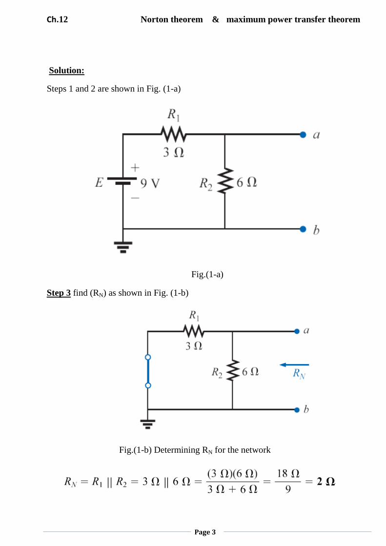
Solution:
Steps 1 and 2 are shown in Fig. (1-a)
Fig.(1-a)
Step 3 find (RN) as shown in Fig. (1-b)
Fig.(1-b) Determining RN for the network

Ch.12 Norton theorem & maximum power transfer theorem
Page 4
Step 4 find (IN) as shown in Fig. (1-c), clearly indicating that the short-circuit connection
between terminals (a) and( b) is in parallel with R2 and eliminates its effect. IN is therefore
the same as through R1, and the full battery voltage appears across R1 .
Fig(1-c)
Step 5: See Fig. (1-d). Substituting the Norton equivalent circuit for the network
external to the resistor RL of fig.(1)
Fig.1-d
Substituting the Norton equivalent circuit for the network external to the resistor RL of fig.(1)
Ch.12 Norton theorem & maximum power transfer theorem
Page 5
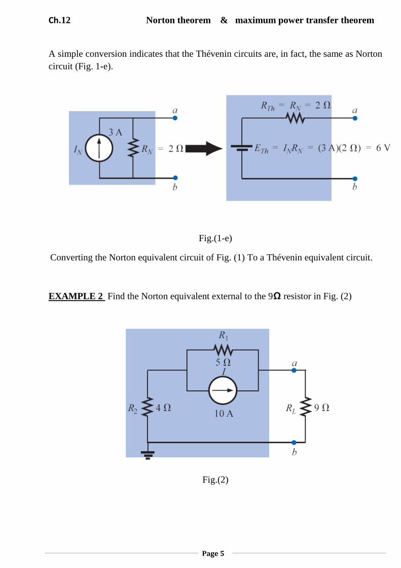
A simple conversion indicates that the Thévenin circuits are, in fact, the same as Norton
circuit (Fig. 1-e).
Fig.(1-e)
Converting the Norton equivalent circuit of Fig. (1) To a Thévenin equivalent circuit.
EXAMPLE 2 Find the Norton equivalent external to the 9Ω resistor in Fig. (2)
Fig.(2)
Ch.12 Norton theorem & maximum power transfer theorem
Page 6
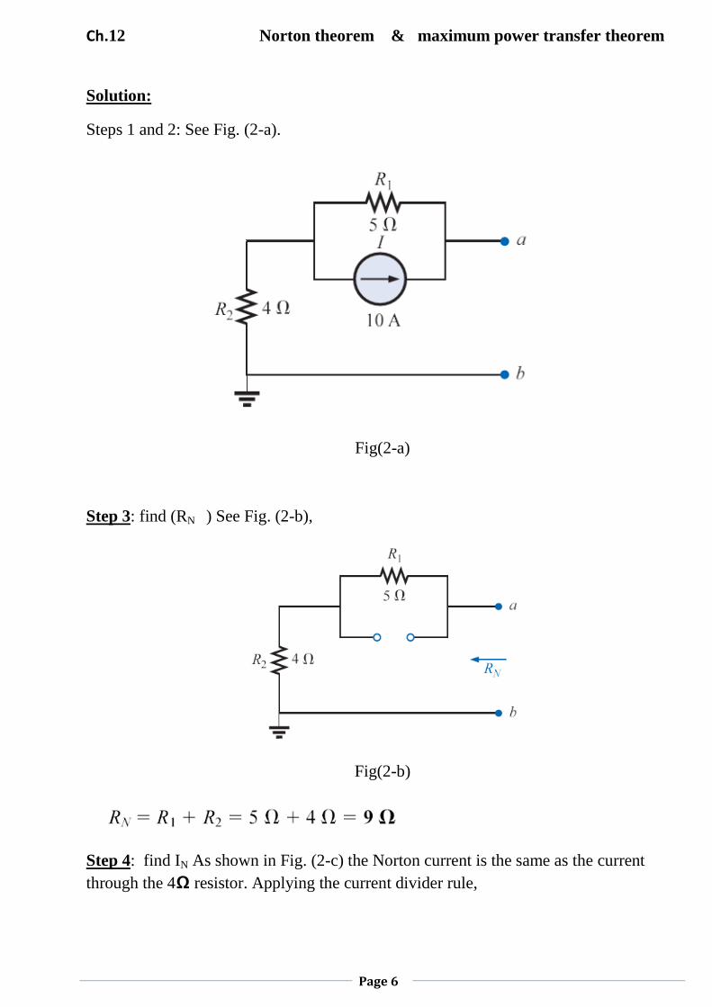
Solution:
Steps 1 and 2: See Fig. (2-a).
Fig(2-a)
Step 3: find (RN ) See Fig. (2-b),
Fig(2-b)
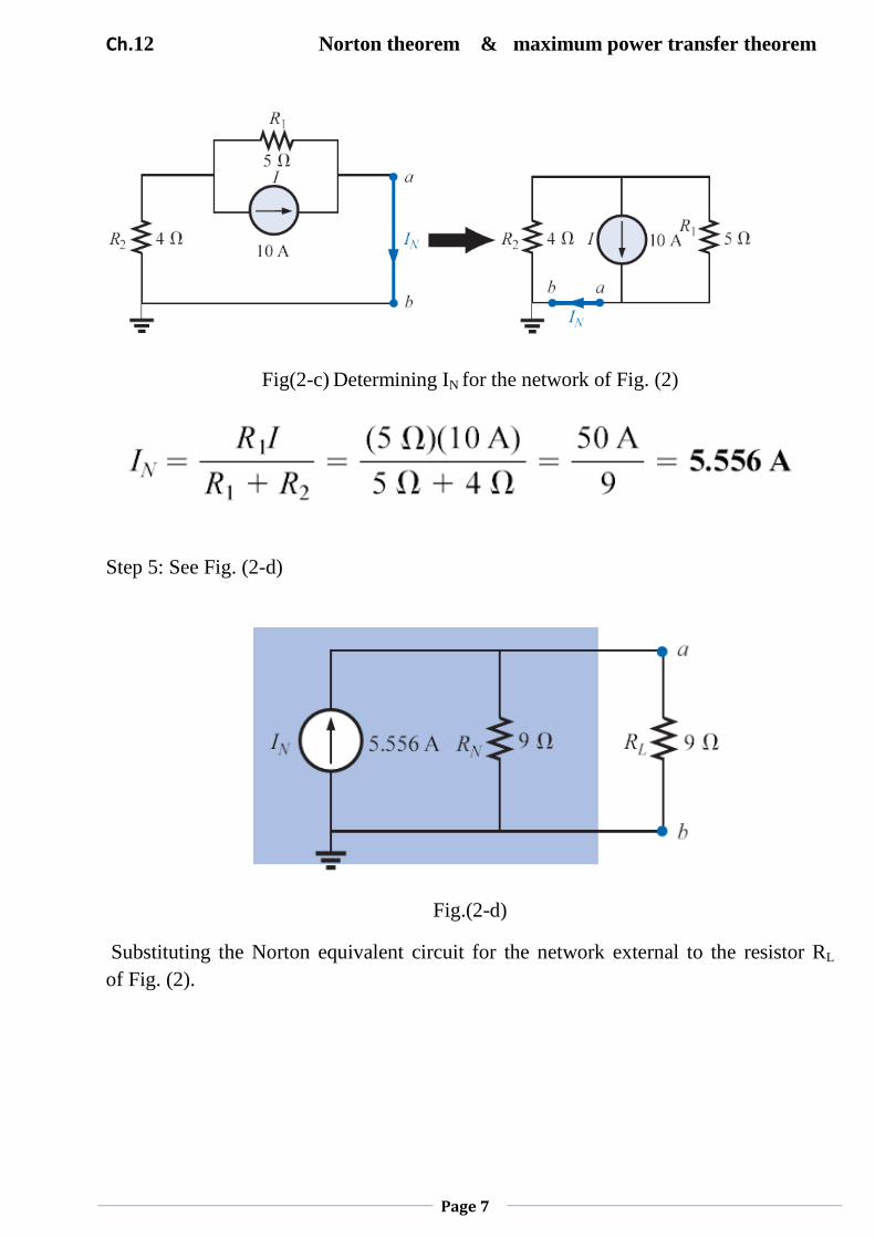
Step 4: find IN As shown in Fig. (2-c) the Norton current is the same as the current
through the 4Ω resistor. Applying the current divider rule,
Ch.12 Norton theorem & maximum power transfer theorem
Page 7
Fig(2-c) Determining IN for the network of Fig. (2)
Step 5: See Fig. (2-d)
Fig.(2-d)
Substituting the Norton equivalent circuit for the network external to the resistor RL
of Fig. (2).
Ch.12 Norton theorem & maximum power transfer theorem
Page 8
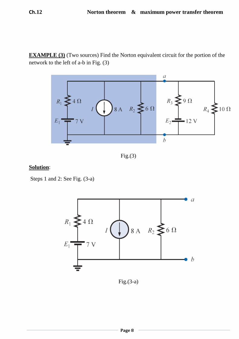
EXAMPLE (3) (Two sources) Find the Norton equivalent circuit for the portion of the
network to the left of a-b in Fig. (3)
Fig.(3)
Solution:
Steps 1 and 2: See Fig. (3-a)
Fig.(3-a)
Ch.12 Norton theorem & maximum power transfer theorem
Page 9
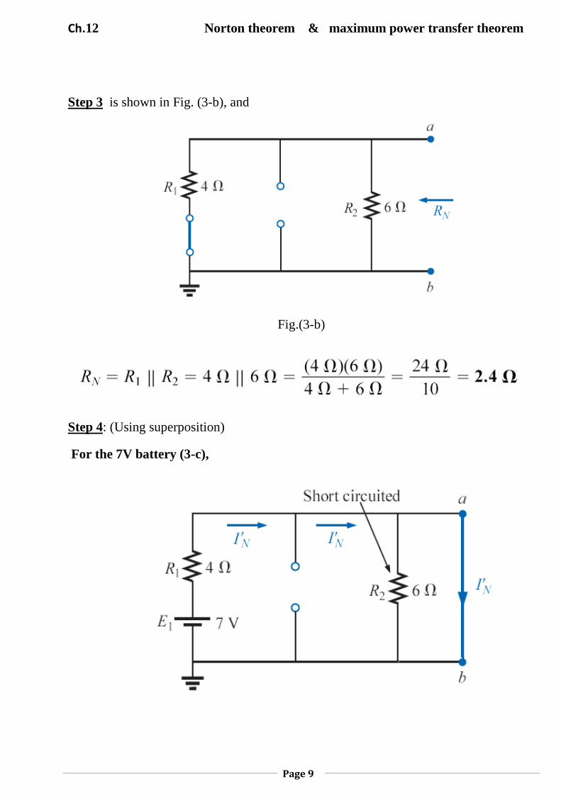
Step 3 is shown in Fig. (3-b), and
Fig.(3-b)
Step 4: (Using superposition)
For the 7V battery (3-c),
Ch.12 Norton theorem & maximum power transfer theorem
Page 10
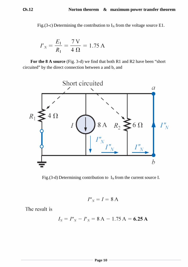
Fig.(3-c) Determining the contribution to IN from the voltage source E1.
For the 8 A source (Fig. 3-d) we find that both R1 and R2 have been “short
circuited” by the direct connection between a and b, and
Fig.(3-d) Determining contribution to IN from the current source I.
Ch.12 Norton theorem & maximum power transfer theorem
Page 11
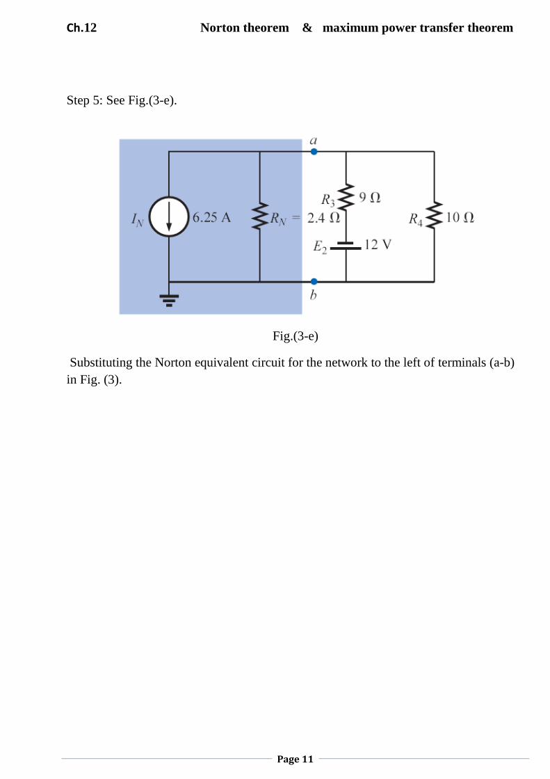
Step 5: See Fig.(3-e).
Fig.(3-e)
Substituting the Norton equivalent circuit for the network to the left of terminals (a-b)
in Fig. (3).
Ch.12 Norton theorem & maximum power transfer theorem
Page 12
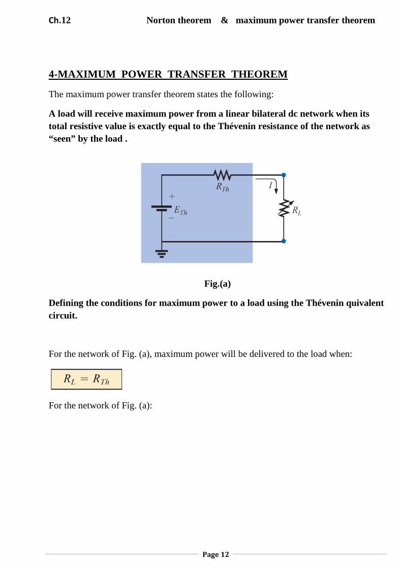
4-MAXIMUM POWER TRANSFER THEOREM
The maximum power transfer theorem states the following:
A load will receive maximum power from a linear bilateral dc network when its
total resistive value is exactly equal to the Thévenin resistance of the network as
“seen” by the load .
Fig.(a)
Defining the conditions for maximum power to a load using the Thévenin quivalent
circuit.
For the network of Fig. (a), maximum power will be delivered to the load when:
For the network of Fig. (a):
Ch.12 Norton theorem & maximum power transfer theorem
Page 13
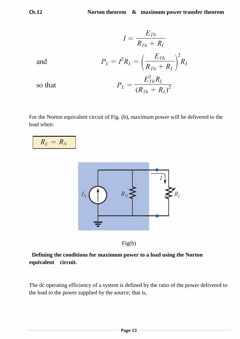
For the Norton equivalent circuit of Fig. (b), maximum power will be delivered to the
load when:
Fig(b)
Defining the conditions for maximum power to a load using the Norton
equivalent circuit.
The dc operating efficiency of a system is defined by the ratio of the power delivered to
the load to the power supplied by the source; that is,
Ch.12 Norton theorem & maximum power transfer theorem
Page 14
The power delivered to RL under maximum power conditions (RL = RTh) is
For the Norton circuit of Fig. (b),
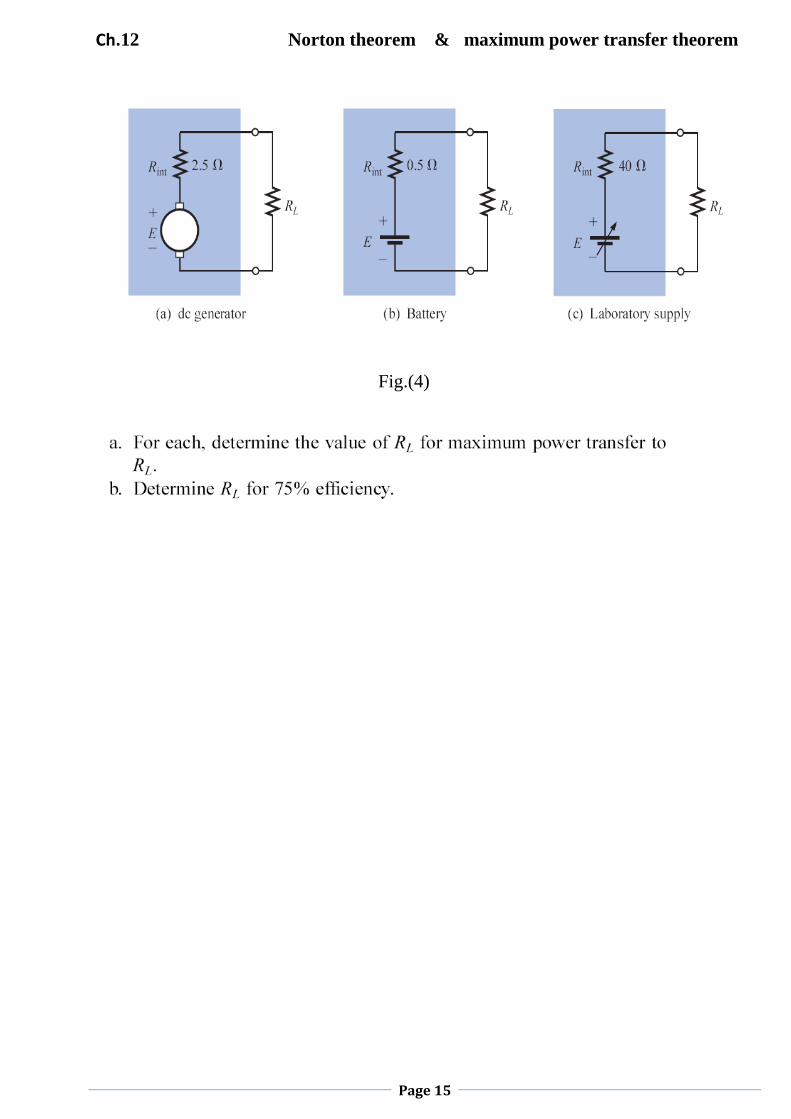
Example 4 : A dc generator, battery, and laboratory supply are connected to a
resistive load RL in Fig. 4(a), (b), and (c), respectively.
Ch.12 Norton theorem & maximum power transfer theorem
Page 15
Fig.(4)
Ch.12 Norton theorem & maximum power transfer theorem
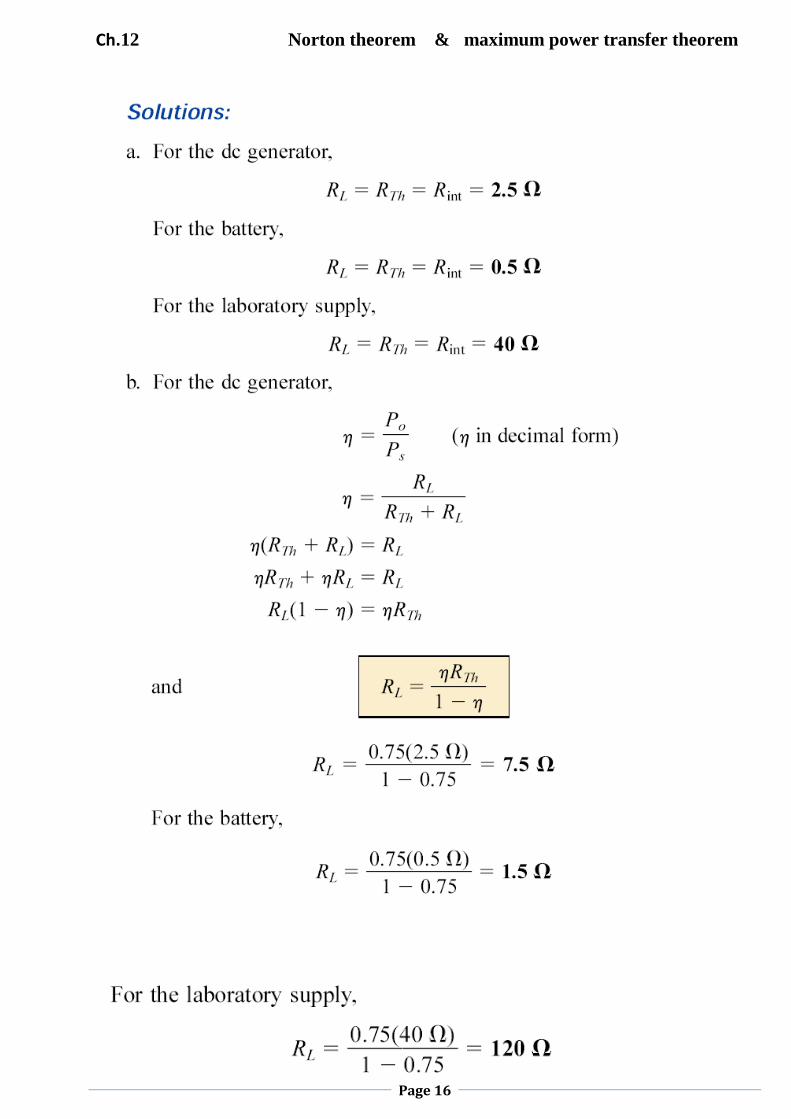
Page 16
Ch.12 Norton theorem & maximum power transfer theorem
Page 17
Note:
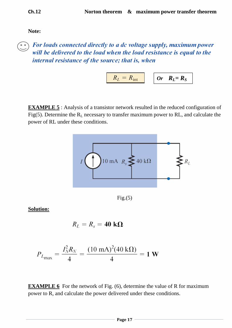
EXAMPLE 5 : Analysis of a transistor network resulted in the reduced configuration of
Fig(5). Determine the RL necessary to transfer maximum power to RL, and calculate the
power of RL under these conditions.
Fig.(5)
Solution:
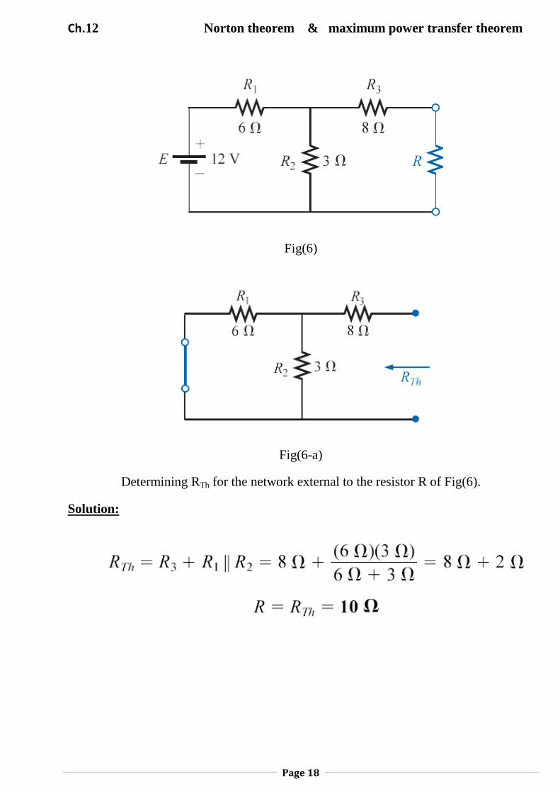
EXAMPLE 6 For the network of Fig. (6), determine the value of R for maximum
power to R, and calculate the power delivered under these conditions.
Or RL= RS
Ch.12 Norton theorem & maximum power transfer theorem
Page 18
Fig(6)
Fig(6-a)
Determining RTh for the network external to the resistor R of Fig(6).
Solution:

Ch.12 Norton theorem & maximum power transfer theorem
Page 19
See Fig. (6-b) ,using voltage divider rule to find VR2:
Where ETh = VR2
Fig.(6-b)
Determining ETh for the network external to the resistor R of Fig. (6)
Then:
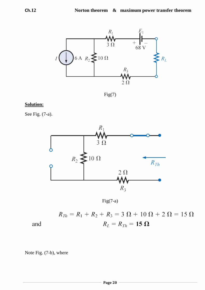
EXAMPLE 7 Find the value of RL in Fig(7) for maximum power to RL, and determine
the maximum power.
Ch.12 Norton theorem & maximum power transfer theorem
Page 20
Fig(7)
Solution:
See Fig. (7-a).
Fig(7-a)
Note Fig. (7-b), where
Ch.12 Norton theorem & maximum power transfer theorem
Page 21
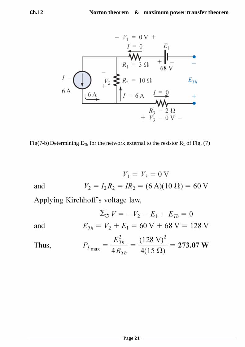
Fig(7-b) Determining ETh for the network external to the resistor RL of Fig. (7)

![[Scheme for 3rd & 4th sems. to be adopted in 2019-20]dcrustm.ac.in/.../uploads/2019/10/B.Tech-2-year_11.6.2019_EEfinal… · Web viewSuperposition theorem, Thevenin theorem, Norton](https://img.pdfslide.net/doc/110x75/5e439d8ac0f60e39110eb606/scheme-for-3rd-4th-sems-to-be-adopted-in-2019-20-web-view-superposition.jpg)