Embed Size (px)
DESCRIPTION
ll
Citation preview
CHAPTER 21
OPTICAL PROPERTIES
Electromagnetic Radiation
21.1 Visible light having a wavelength of 6 10-7 m appears orange. Compute the frequency and energy
of a photon of this light.
Solution
In order to compute the frequency of a photon of orange light, we must use Equation 21.2 as
€
ν =c
λ=
3 × 10⁸ m/s
6 × 10⁻⁷ m= 5 × 10¹⁴ s-1
Now, for the energy computation, we employ Equation 21.3 as follows:
€
E =hc
λ=
(6.63 × 10⁻³⁴ J - s)(3 × 10⁸ m/s)6 × 10−7 m
€
= 3.31 × 10⁻¹⁹ J (2.07 eV)
Excerpts from this work may be reproduced by instructors for distribution on a not-for-profit basis for testing or instructional purposes only to students enrolled in courses for which the textbook has been adopted. Any other reproduction or translation of this work beyond that permitted by Sections 107 or 108 of the 1976 United States Copyright Act without the permission of the copyright owner is unlawful.
Light Interactions with Solids
21.2 Distinguish between materials that are opaque, translucent, and transparent in terms of their
appearance and light transmittance.
Solution
Opaque materials are impervious to light transmission; it is not possible to see through them.
Light is transmitted diffusely through translucent materials (there is some internal light scattering).
Objects are not clearly distinguishable when viewed through a translucent material.
Virtually all of the incident light is transmitted through transparent materials, and one can see clearly
through them.
Excerpts from this work may be reproduced by instructors for distribution on a not-for-profit basis for testing or instructional purposes only to students enrolled in courses for which the textbook has been adopted. Any other reproduction or translation of this work beyond that permitted by Sections 107 or 108 of the 1976 United States Copyright Act without the permission of the copyright owner is unlawful.
Atomic and Electronic Interactions
21.3 (a) Briefly describe the phenomenon of electronic polarization by electromagnetic radiation. (b)
What are two consequences of electronic polarization in transparent materials?
Solution
(a) The phenomenon of electronic polarization by electromagnetic radiation is described in Section 21.4.
(b) Two consequences of electronic polarization in transparent materials are absorption and refraction.
Excerpts from this work may be reproduced by instructors for distribution on a not-for-profit basis for testing or instructional purposes only to students enrolled in courses for which the textbook has been adopted. Any other reproduction or translation of this work beyond that permitted by Sections 107 or 108 of the 1976 United States Copyright Act without the permission of the copyright owner is unlawful.
Optical Properties of Metals
21.4 Briefly explain why metals are opaque to electromagnetic radiation having photon energies within
the visible region of the spectrum.
Solution
The electron band structures of metals are such that empty and available electron states are adjacent to
filled states. Electron excitations from filled to empty states are possible with the absorption of electromagnetic
radiation having frequencies within the visible spectrum, according to Equation 21.6. The light energy is totally
absorbed or reflected, and, since none is transmitted, the material is opaque.
Excerpts from this work may be reproduced by instructors for distribution on a not-for-profit basis for testing or instructional purposes only to students enrolled in courses for which the textbook has been adopted. Any other reproduction or translation of this work beyond that permitted by Sections 107 or 108 of the 1976 United States Copyright Act without the permission of the copyright owner is unlawful.
Refraction
21.5 In ionic materials, how does the size of the component ions affect the extent of electronic
polarization?
Solution
In ionic materials, the larger the size of the component ions the greater the degree of electronic
polarization.
Excerpts from this work may be reproduced by instructors for distribution on a not-for-profit basis for testing or instructional purposes only to students enrolled in courses for which the textbook has been adopted. Any other reproduction or translation of this work beyond that permitted by Sections 107 or 108 of the 1976 United States Copyright Act without the permission of the copyright owner is unlawful.
21.6 Can a material have an index of refraction less than unity? Why or why not?
Solution
In order for a material to have an index of refraction less than unity, the velocity of light in the material
(v) would necessarily have to be greater than the velocity of light in a vacuum (Equation 21.7). This is not
possible.
Excerpts from this work may be reproduced by instructors for distribution on a not-for-profit basis for testing or instructional purposes only to students enrolled in courses for which the textbook has been adopted. Any other reproduction or translation of this work beyond that permitted by Sections 107 or 108 of the 1976 United States Copyright Act without the permission of the copyright owner is unlawful.
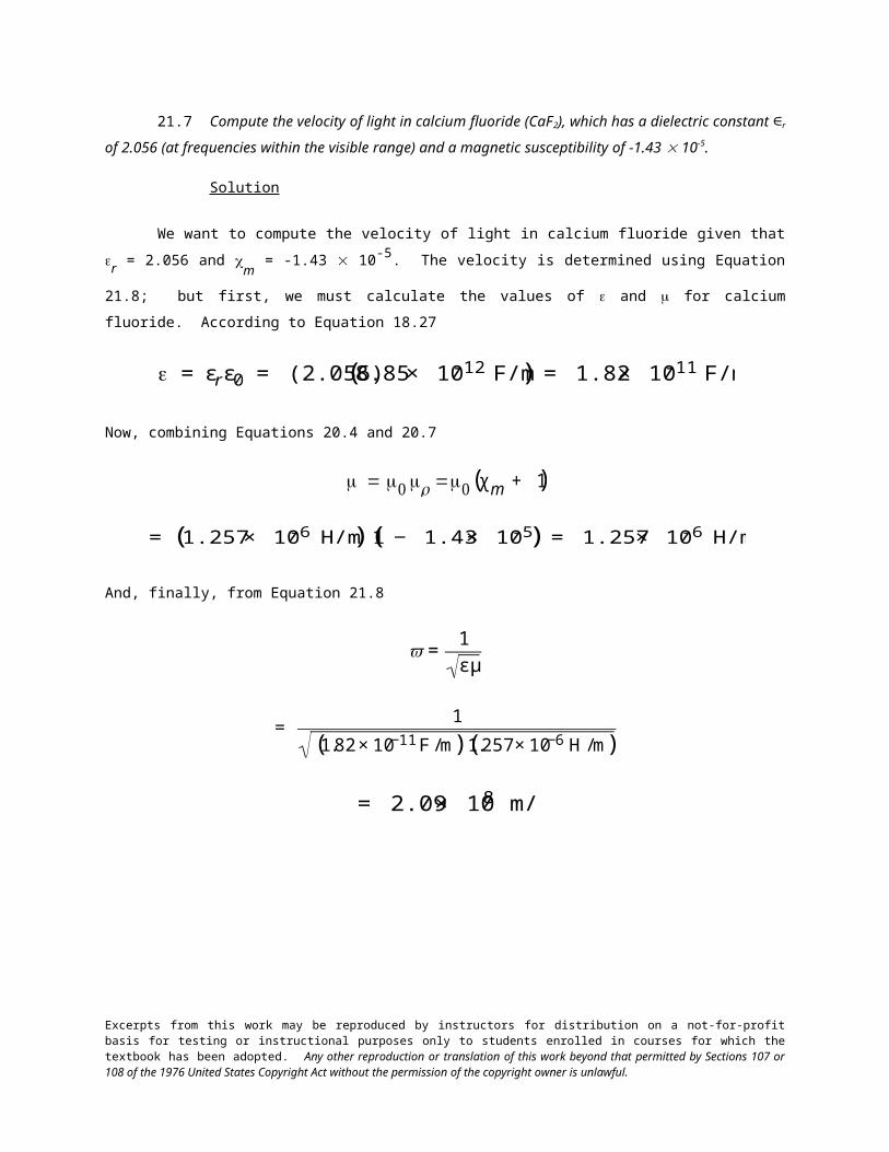
21.7 Compute the velocity of light in calcium fluoride (CaF2), which has a dielectric constant ∈r of
2.056 (at frequencies within the visible range) and a magnetic susceptibility of -1.43 10-5.
Solution
We want to compute the velocity of light in calcium fluoride given that r = 2.056 and m
= -1.43 10-
5. The velocity is determined using Equation 21.8; but first, we must calculate the values of and for calcium
fluoride. According to Equation 18.27
€
= εrε0 = (2.056)(8.85 × 10⁻¹² F/m) = 1.82 × 10⁻¹¹ F/m
Now, combining Equations 20.4 and 20.7
€
= 0 r =0(χ m + 1)
€
= (1.257 × 10⁻⁶ H/m)(1 − 1.43 × 10⁻⁵) = 1.257 × 10⁻⁶ H/m
And, finally, from Equation 21.8
€
v =1
εμ
€
= 1
(1.82 × 10⁻¹¹ F /m)(1.257 × 10−6 H /m)
€
= 2.09 × 10⁸ m/s
Excerpts from this work may be reproduced by instructors for distribution on a not-for-profit basis for testing or instructional purposes only to students enrolled in courses for which the textbook has been adopted. Any other reproduction or translation of this work beyond that permitted by Sections 107 or 108 of the 1976 United States Copyright Act without the permission of the copyright owner is unlawful.
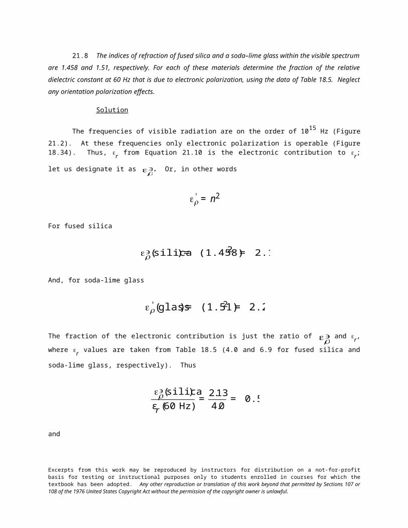
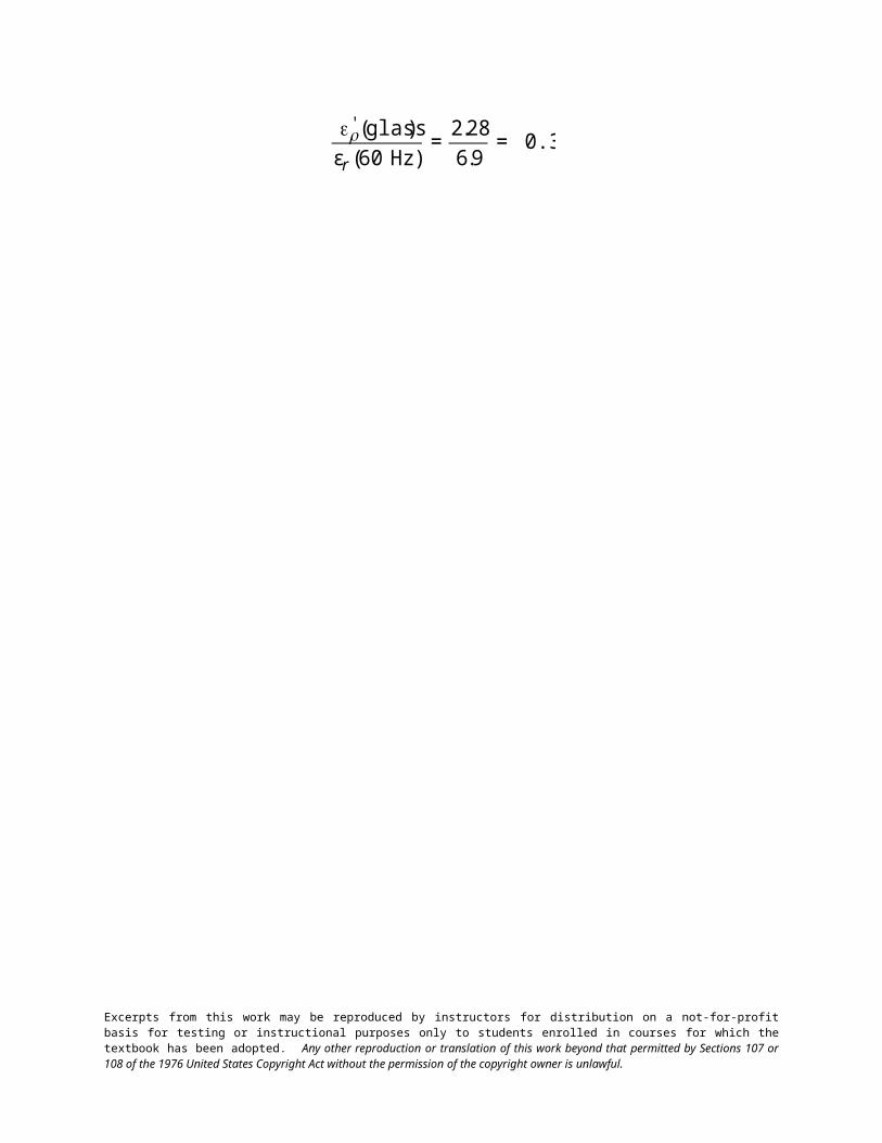
21.8 The indices of refraction of fused silica and a soda–lime glass within the visible spectrum are 1.458
and 1.51, respectively. For each of these materials determine the fraction of the relative dielectric constant at 60
Hz that is due to electronic polarization, using the data of Table 18.5. Neglect any orientation polarization
effects.
Solution
The frequencies of visible radiation are on the order of 1015 Hz (Figure 21.2). At these frequencies only electronic polarization is operable (Figure 18.34). Thus, r
from Equation 21.10 is the electronic contribution to
r; let us designate it as
€
r'. Or, in other words
€
r' = n2
For fused silica
€
r' (silica) = (1.458)2 = 2.13
And, for soda-lime glass
€
r' (glass) = (1.51)2 = 2.28
The fraction of the electronic contribution is just the ratio of
€
r' and r, where r values are taken from Table 18.5
(4.0 and 6.9 for fused silica and soda-lime glass, respectively). Thus
€
r' (silica)
εr (60 Hz)=
2.13
4.0= 0.53
and
€
r' (glass)
εr (60 Hz)=
2.28
6.9= 0.33
Excerpts from this work may be reproduced by instructors for distribution on a not-for-profit basis for testing or instructional purposes only to students enrolled in courses for which the textbook has been adopted. Any other reproduction or translation of this work beyond that permitted by Sections 107 or 108 of the 1976 United States Copyright Act without the permission of the copyright owner is unlawful.
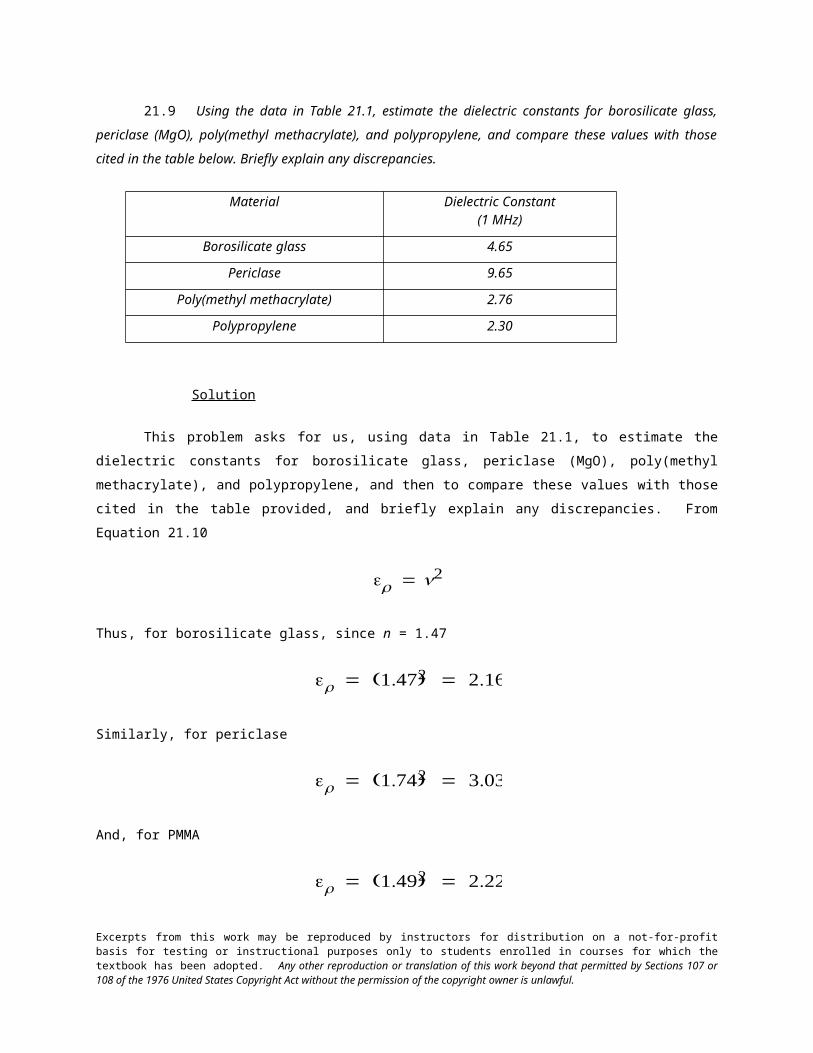
21.9 Using the data in Table 21.1, estimate the dielectric constants for borosilicate glass, periclase
(MgO), poly(methyl methacrylate), and polypropylene, and compare these values with those cited in the table
below. Briefly explain any discrepancies.
Material Dielectric Constant(1 MHz)
Borosilicate glass 4.65
Periclase 9.65
Poly(methyl methacrylate) 2.76
Polypropylene 2.30
Solution
This problem asks for us, using data in Table 21.1, to estimate the dielectric constants for borosilicate
glass, periclase (MgO), poly(methyl methacrylate), and polypropylene, and then to compare these values with
those cited in the table provided, and briefly explain any discrepancies. From Equation 21.10
€
r = n2
Thus, for borosilicate glass, since n = 1.47
€
r = (1.47)2 = 2.16
Similarly, for periclase
€
r = (1.74)2 = 3.03
And, for PMMA
€
r = (1.49)2 = 2.22
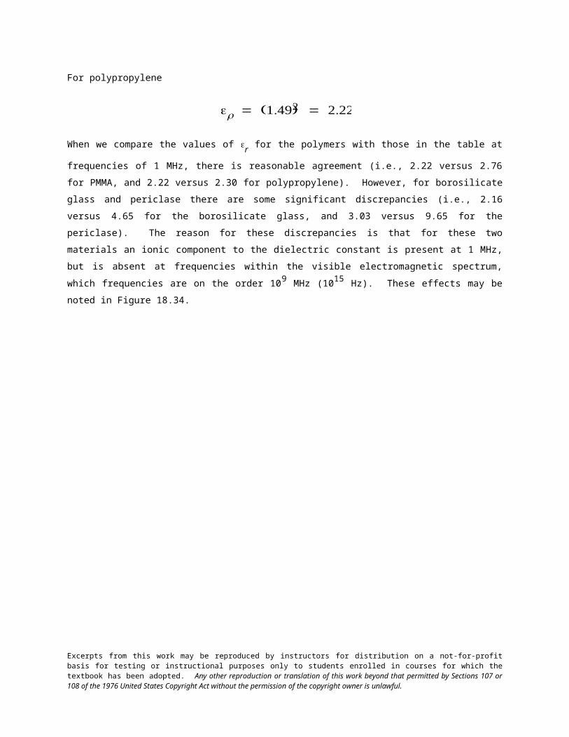
For polypropylene
€
r = (1.49)2 = 2.22
Excerpts from this work may be reproduced by instructors for distribution on a not-for-profit basis for testing or instructional purposes only to students enrolled in courses for which the textbook has been adopted. Any other reproduction or translation of this work beyond that permitted by Sections 107 or 108 of the 1976 United States Copyright Act without the permission of the copyright owner is unlawful.
When we compare the values of r for the polymers with those in the table at frequencies of 1 MHz, there is
reasonable agreement (i.e., 2.22 versus 2.76 for PMMA, and 2.22 versus 2.30 for polypropylene). However, for
borosilicate glass and periclase there are some significant discrepancies (i.e., 2.16 versus 4.65 for the borosilicate
glass, and 3.03 versus 9.65 for the periclase). The reason for these discrepancies is that for these two materials an
ionic component to the dielectric constant is present at 1 MHz, but is absent at frequencies within the visible
electromagnetic spectrum, which frequencies are on the order 109 MHz (1015 Hz). These effects may be noted in
Figure 18.34.
Excerpts from this work may be reproduced by instructors for distribution on a not-for-profit basis for testing or instructional purposes only to students enrolled in courses for which the textbook has been adopted. Any other reproduction or translation of this work beyond that permitted by Sections 107 or 108 of the 1976 United States Copyright Act without the permission of the copyright owner is unlawful.
21.10 Briefly describe the phenomenon of dispersion in a transparent medium.
Solution
Dispersion in a transparent medium is the phenomenon wherein the index of refraction varies slightly
with the wavelength of the electromagnetic radiation.
Excerpts from this work may be reproduced by instructors for distribution on a not-for-profit basis for testing or instructional purposes only to students enrolled in courses for which the textbook has been adopted. Any other reproduction or translation of this work beyond that permitted by Sections 107 or 108 of the 1976 United States Copyright Act without the permission of the copyright owner is unlawful.
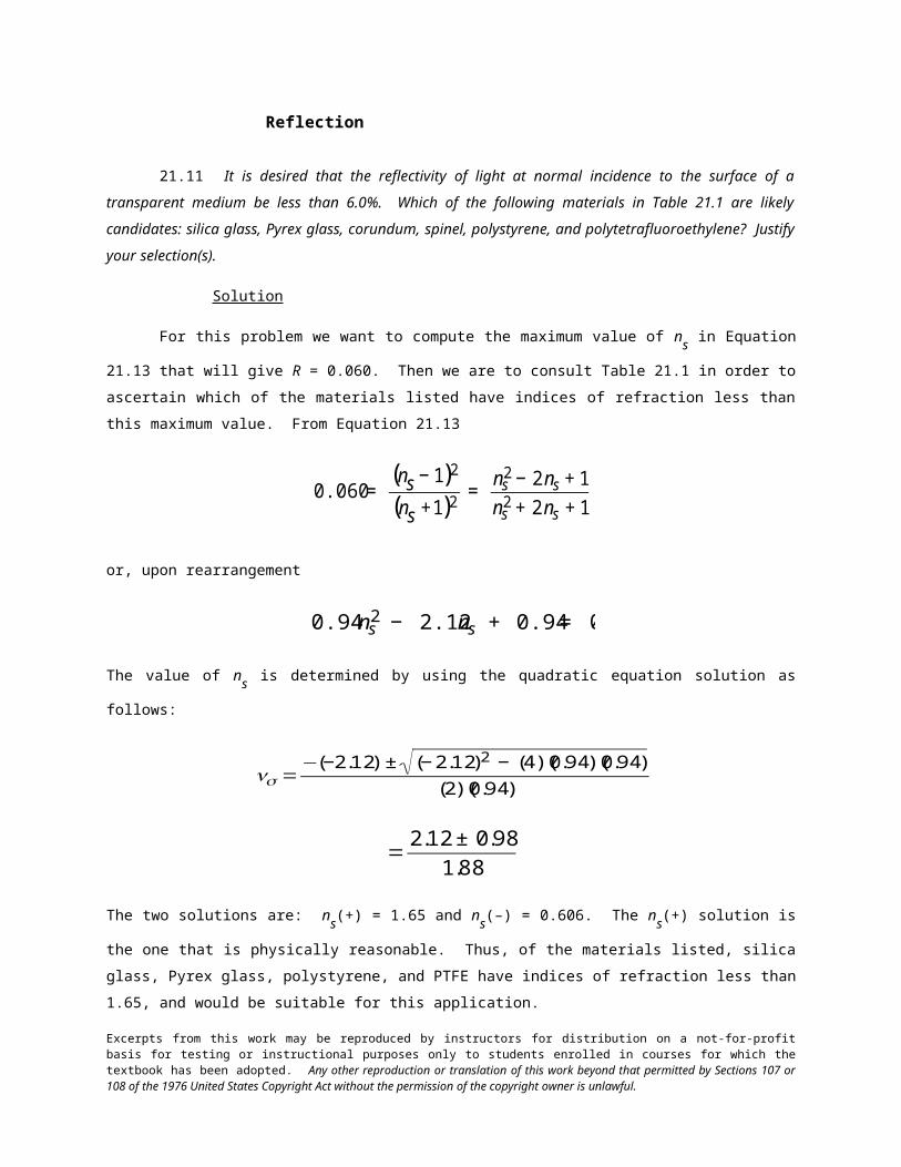
Reflection
21.11 It is desired that the reflectivity of light at normal incidence to the surface of a transparent
medium be less than 6.0%. Which of the following materials in Table 21.1 are likely candidates: silica glass,
Pyrex glass, corundum, spinel, polystyrene, and polytetrafluoroethylene? Justify your selection(s).
Solution
For this problem we want to compute the maximum value of ns in Equation 21.13 that will give R =
0.060. Then we are to consult Table 21.1 in order to ascertain which of the materials listed have indices of
refraction less than this maximum value. From Equation 21.13
€
0.060 = (ns − 1)2
(ns +1)2=
ns2 − 2 ns + 1
ns2 + 2 ns + 1
or, upon rearrangement
€
0.94 ns2 − 2.12 ns + 0.94 = 0
The value of ns is determined by using the quadratic equation solution as follows:
€
ns =−(−2.12) ± (− 2.12)2 − (4)(0.94)(0.94)
(2)(0.94)
€
=2.12 ± 0.98
1.88
The two solutions are: ns(+) = 1.65 and ns(–) = 0.606. The ns(+) solution is the one that is physically reasonable.
Thus, of the materials listed, silica glass, Pyrex glass, polystyrene, and PTFE have indices of refraction less than
1.65, and would be suitable for this application.
Excerpts from this work may be reproduced by instructors for distribution on a not-for-profit basis for testing or instructional purposes only to students enrolled in courses for which the textbook has been adopted. Any other reproduction or translation of this work beyond that permitted by Sections 107 or 108 of the 1976 United States Copyright Act without the permission of the copyright owner is unlawful.
21.12 Briefly explain how reflection losses of transparent materials are minimized by thin surface
coatings.
Solution
The thickness and dielectric constant of a thin surface coating are selected such that there is destructive
interference between the light beam that is reflected from the lens-coating interface and the light beam that is
reflected from the coating-air interface; thus, the net intensity of the total reflected beam is very low.
Excerpts from this work may be reproduced by instructors for distribution on a not-for-profit basis for testing or instructional purposes only to students enrolled in courses for which the textbook has been adopted. Any other reproduction or translation of this work beyond that permitted by Sections 107 or 108 of the 1976 United States Copyright Act without the permission of the copyright owner is unlawful.
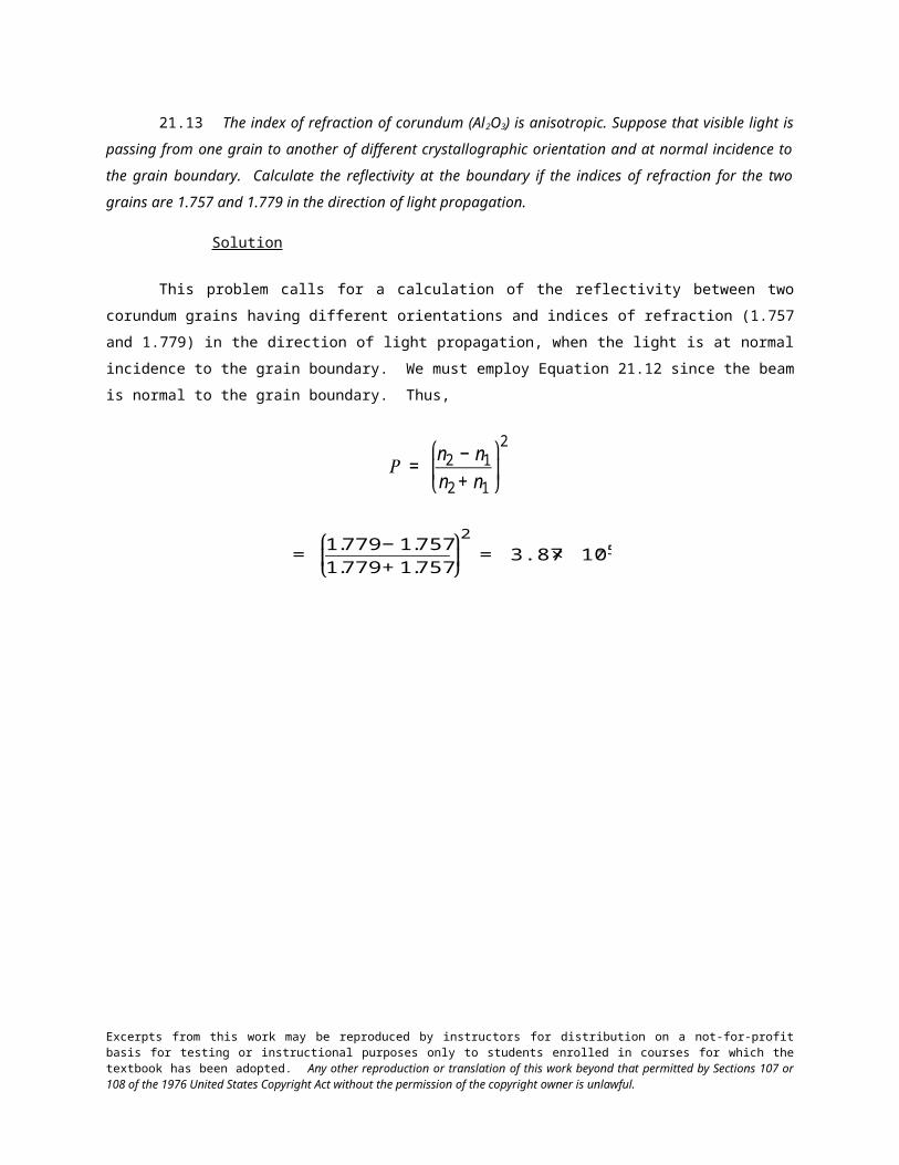
21.13 The index of refraction of corundum (Al2O3) is anisotropic. Suppose that visible light is passing
from one grain to another of different crystallographic orientation and at normal incidence to the grain boundary.
Calculate the reflectivity at the boundary if the indices of refraction for the two grains are 1.757 and 1.779 in the
direction of light propagation.
Solution
This problem calls for a calculation of the reflectivity between two corundum grains having different
orientations and indices of refraction (1.757 and 1.779) in the direction of light propagation, when the light is at
normal incidence to the grain boundary. We must employ Equation 21.12 since the beam is normal to the grain
boundary. Thus,
€
R = n2 − n1
n2 + n1
⎛
⎝ ⎜
⎞
⎠ ⎟2
€
= 1.779 − 1.757
1.779 + 1.757
⎛
⎝ ⎜
⎞
⎠ ⎟2
= 3.87 × 10⁻⁵
Excerpts from this work may be reproduced by instructors for distribution on a not-for-profit basis for testing or instructional purposes only to students enrolled in courses for which the textbook has been adopted. Any other reproduction or translation of this work beyond that permitted by Sections 107 or 108 of the 1976 United States Copyright Act without the permission of the copyright owner is unlawful.
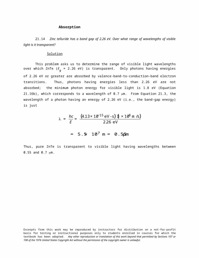
Absorption
21.14 Zinc telluride has a band gap of 2.26 eV. Over what range of wavelengths of visible light is it
transparent?
Solution
This problem asks us to determine the range of visible light wavelengths over which ZnTe (Eg = 2.26 eV)
is transparent. Only photons having energies of 2.26 eV or greater are absorbed by valence-band-to-conduction-
band electron transitions. Thus, photons having energies less than 2.26 eV are not absorbed; the minimum
photon energy for visible light is 1.8 eV (Equation 21.16b), which corresponds to a wavelength of 0.7 m. From
Equation 21.3, the wavelength of a photon having an energy of 2.26 eV (i.e., the band-gap energy) is just
€
λ = hc
E=
(4.13 × 10⁻¹⁵ eV - s)(3 × 10⁸ m/s)2.26 eV
€
= 5.5 × 10⁻⁷ m = 0.55 μm
Thus, pure ZnTe is transparent to visible light having wavelengths between 0.55 and 0.7 m.
Excerpts from this work may be reproduced by instructors for distribution on a not-for-profit basis for testing or instructional purposes only to students enrolled in courses for which the textbook has been adopted. Any other reproduction or translation of this work beyond that permitted by Sections 107 or 108 of the 1976 United States Copyright Act without the permission of the copyright owner is unlawful.
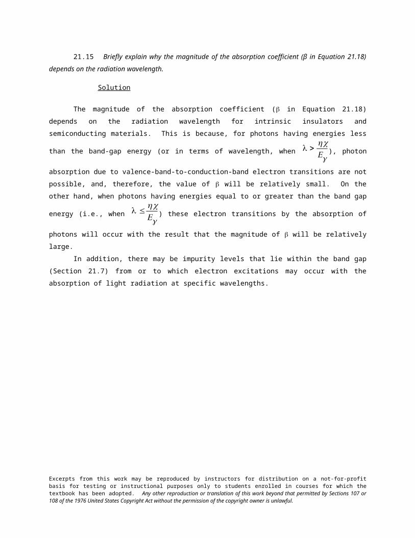
21.15 Briefly explain why the magnitude of the absorption coefficient (β in Equation 21.18) depends on
the radiation wavelength.
Solution
The magnitude of the absorption coefficient ( in Equation 21.18) depends on the radiation wavelength
for intrinsic insulators and semiconducting materials. This is because, for photons having energies less than the
band-gap energy (or in terms of wavelength, when
€
λ >h cEg
), photon absorption due to valence-band-to-conduction-
band electron transitions are not possible, and, therefore, the value of will be relatively small. On the other
hand, when photons having energies equal to or greater than the band gap energy (i.e., when
€
λ ≤h cEg
) these
electron transitions by the absorption of photons will occur with the result that the magnitude of will be
relatively large.
In addition, there may be impurity levels that lie within the band gap (Section 21.7) from or to which
electron excitations may occur with the absorption of light radiation at specific wavelengths.
Excerpts from this work may be reproduced by instructors for distribution on a not-for-profit basis for testing or instructional purposes only to students enrolled in courses for which the textbook has been adopted. Any other reproduction or translation of this work beyond that permitted by Sections 107 or 108 of the 1976 United States Copyright Act without the permission of the copyright owner is unlawful.
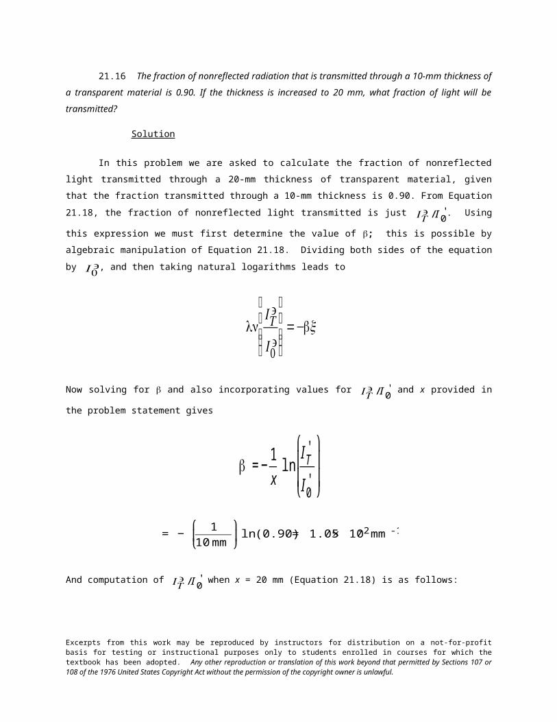
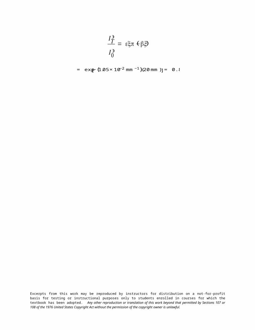
21.16 The fraction of nonreflected radiation that is transmitted through a 10-mm thickness of a
transparent material is 0.90. If the thickness is increased to 20 mm, what fraction of light will be transmitted?
Solution
In this problem we are asked to calculate the fraction of nonreflected light transmitted through a 20-mm
thickness of transparent material, given that the fraction transmitted through a 10-mm thickness is 0.90. From
Equation 21.18, the fraction of nonreflected light transmitted is just
€
IT' / I0
' . Using this expression we must first
determine the value of ; this is possible by algebraic manipulation of Equation 21.18. Dividing both sides of the
equation by
€
I 0' , and then taking natural logarithms leads to
€
lnIT'
I 0'
⎛
⎝
⎜ ⎜ ⎜
⎞
⎠
⎟ ⎟ ⎟=−x
Now solving for and also incorporating values for
€
IT' / I0
' and x provided in the problem statement gives
€
= −1
xln
IT'
I0'
⎛
⎝
⎜ ⎜
⎞
⎠
⎟ ⎟
€
= − 1
10 mm
⎛
⎝ ⎜
⎞
⎠ ⎟ ln (0.90) = 1.05 × 10⁻² mm-1
And computation of
€
IT' / I0
' when x = 20 mm (Equation 21.18) is as follows:
€
IT'
I 0'= (exp− x)
€
= exp −(1.05 × 10⁻² mm−1)(20 mm)[ ] = 0.81
Excerpts from this work may be reproduced by instructors for distribution on a not-for-profit basis for testing or instructional purposes only to students enrolled in courses for which the textbook has been adopted. Any other reproduction or translation of this work beyond that permitted by Sections 107 or 108 of the 1976 United States Copyright Act without the permission of the copyright owner is unlawful.
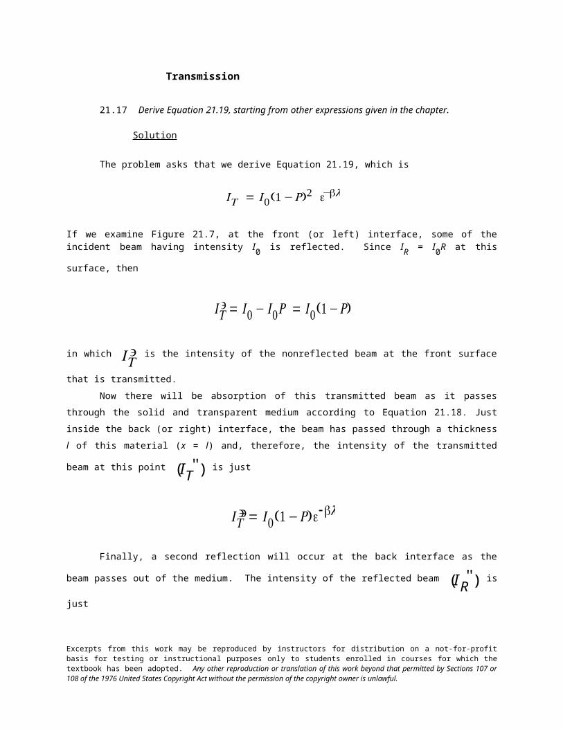
Transmission
21.17 Derive Equation 21.19, starting from other expressions given in the chapter.
Solution
The problem asks that we derive Equation 21.19, which is
€
IT = I 0(1 −R)2 e−l
If we examine Figure 21.7, at the front (or left) interface, some of the incident beam having intensity I0 is
reflected. Since IR = I0R at this surface, then
€
IT' = I 0 − I 0R = I 0(1 −R)
in which
€
IT' is the intensity of the nonreflected beam at the front surface that is transmitted.
Now there will be absorption of this transmitted beam as it passes through the solid and transparent
medium according to Equation 21.18. Just inside the back (or right) interface, the beam has passed through a
thickness l of this material (x = l) and, therefore, the intensity of the transmitted beam at this point
€
(IT'' ) is just
€
IT'' = I 0(1 −R)e-l
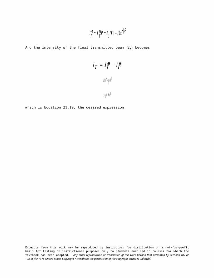
Finally, a second reflection will occur at the back interface as the beam passes out of the medium. The
intensity of the reflected beam
€
(IR'' ) is just
€
IR'' = I T
'' R= I 0R(1 −R)e-l
And the intensity of the final transmitted beam (IT) becomes
€
IT = IT'' − IR
''
€
= I 0(1 −R)e-l − I 0R(1 −R)e-l
Excerpts from this work may be reproduced by instructors for distribution on a not-for-profit basis for testing or instructional purposes only to students enrolled in courses for which the textbook has been adopted. Any other reproduction or translation of this work beyond that permitted by Sections 107 or 108 of the 1976 United States Copyright Act without the permission of the copyright owner is unlawful.
€
= I 0(1 −R)2 e-l
which is Equation 21.19, the desired expression.
Excerpts from this work may be reproduced by instructors for distribution on a not-for-profit basis for testing or instructional purposes only to students enrolled in courses for which the textbook has been adopted. Any other reproduction or translation of this work beyond that permitted by Sections 107 or 108 of the 1976 United States Copyright Act without the permission of the copyright owner is unlawful.
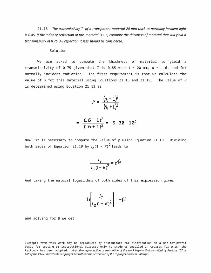
21.18 The transmissivity T of a transparent material 20 mm thick to normally incident light is 0.85. If
the index of refraction of this material is 1.6, compute the thickness of material that will yield a transmissivity of
0.75. All reflection losses should be considered.
Solution
We are asked to compute the thickness of material to yield a transmissivity of 0.75 given that T is 0.85
when l = 20 mm, n = 1.6, and for normally incident radiation. The first requirement is that we calculate the value
of for this material using Equations 21.13 and 21.19. The value of R is determined using Equation 21.13 as
€
R = (ns − 1)2
(ns +1)2
€
= (1.6 − 1)2
(1.6 + 1)2= 5.33 × 10⁻²
Now, it is necessary to compute the value of using Equation 21.19. Dividing both sides of Equation 21.19 by
I0(1 – R)2 leads to
€
ITI 0 (1 − R)2
= e-βl
And taking the natural logarithms of both sides of this expression gives
€
lnIT
I0 (1 − R)2
⎡
⎣ ⎢ ⎢
⎤
⎦ ⎥ ⎥= −βl
and solving for we get
€
=−1l
lnIT
I 0 (1 − R)2
⎡
⎣ ⎢ ⎢
⎤
⎦ ⎥ ⎥
Since the transmissivity is T is equal to IT/I0, then the above equation takes the form
Excerpts from this work may be reproduced by instructors for distribution on a not-for-profit basis for testing or instructional purposes only to students enrolled in courses for which the textbook has been adopted. Any other reproduction or translation of this work beyond that permitted by Sections 107 or 108 of the 1976 United States Copyright Act without the permission of the copyright owner is unlawful.
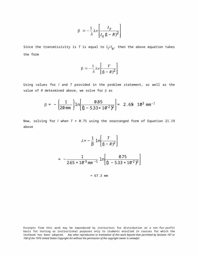
€
=−1l
lnT
(1 − R)2
⎡
⎣ ⎢ ⎢
⎤
⎦ ⎥ ⎥
Using values for l and T provided in the problem statement, as well as the value of R determined above, we solve
for as
€
= −1
20 mm
⎛
⎝ ⎜
⎞
⎠ ⎟ln
0.85
(1 − 5.33 × 10⁻²)2
⎡
⎣ ⎢
⎤
⎦ ⎥= 2.65 × 10⁻³ mm-1
Now, solving for l when T = 0.75 using the rearranged form of Equation 21.19 above
€
l = −1
βln
T
(1 − R)2
⎡
⎣ ⎢
⎤
⎦ ⎥
€
= −1
2.65 × 10⁻³ mm−1ln
0.75
(1 − 5.33 × 10⁻²)2
⎡
⎣ ⎢
⎤
⎦ ⎥
= 67.3 mm
Excerpts from this work may be reproduced by instructors for distribution on a not-for-profit basis for testing or instructional purposes only to students enrolled in courses for which the textbook has been adopted. Any other reproduction or translation of this work beyond that permitted by Sections 107 or 108 of the 1976 United States Copyright Act without the permission of the copyright owner is unlawful.
Color
21.19 Briefly explain what determines the characteristic color of (a) a metal and (b) a transparent
nonmetal.
Solution
(a) The characteristic color of a metal is determined by the distribution of wavelengths of the
nonabsorbed light radiation that is reflected.
(b) The characteristic color of a transparent nonmetal is determined by the distribution of wavelengths of
the nonabsorbed light radiation that is transmitted through the material.
Excerpts from this work may be reproduced by instructors for distribution on a not-for-profit basis for testing or instructional purposes only to students enrolled in courses for which the textbook has been adopted. Any other reproduction or translation of this work beyond that permitted by Sections 107 or 108 of the 1976 United States Copyright Act without the permission of the copyright owner is unlawful.
21.20 Briefly explain why some transparent materials appear colored while others are colorless.
Solution
For a transparent material that appears colorless, any absorption within its interior is the same for all
visible wavelengths. On the other hand, if there is any selective absorption of visible light (usually by electron
excitations), the material will appear colored, its color being dependent on the frequency distribution of the
transmitted light beam.
Excerpts from this work may be reproduced by instructors for distribution on a not-for-profit basis for testing or instructional purposes only to students enrolled in courses for which the textbook has been adopted. Any other reproduction or translation of this work beyond that permitted by Sections 107 or 108 of the 1976 United States Copyright Act without the permission of the copyright owner is unlawful.
Opacity and Translucency in Insulators
21.21 Briefly describe the three absorption mechanisms in nonmetallic materials.
The three absorption mechanisms in nonmetallic materials involve electronic polarization, electron
transitions, and scattering. Electronic polarization is described in Section 21.4; absorption by electron transitions
is discussed in Sections 21.4 and 21.7; and scattering is discussed in Section 21.10.
Excerpts from this work may be reproduced by instructors for distribution on a not-for-profit basis for testing or instructional purposes only to students enrolled in courses for which the textbook has been adopted. Any other reproduction or translation of this work beyond that permitted by Sections 107 or 108 of the 1976 United States Copyright Act without the permission of the copyright owner is unlawful.
21.22 Briefly explain why amorphous polymers are transparent, while predominantly crystalline
polymers appear opaque or, at best, translucent.
Solution
Amorphous polymers are normally transparent because there is no scattering of a light beam within the
material. However, for semicrystalline polymers, visible light will be scattered at boundaries between amorphous
and crystalline regions since they have different indices of refraction. This leads to translucency or, for extensive
scattering, opacity, except for semicrystalline polymers having very small crystallites.
Excerpts from this work may be reproduced by instructors for distribution on a not-for-profit basis for testing or instructional purposes only to students enrolled in courses for which the textbook has been adopted. Any other reproduction or translation of this work beyond that permitted by Sections 107 or 108 of the 1976 United States Copyright Act without the permission of the copyright owner is unlawful.
Luminescence
Photoconductivity
Lasers
21.23 (a) In your own words describe briefly the phenomenon of luminescence.
(b) What is the distinction between fluorescence and phosphorescence?
Solution
(a) The phenomenon of luminescence is described in Section 21.11.
(b) The feature that distinguishes fluorescence from phosphorescence is the magnitude of the time
interval between photon absorption and reemission events. Fluorescence is for delay times less than a second;
phosphorescence occurs for longer times.
Excerpts from this work may be reproduced by instructors for distribution on a not-for-profit basis for testing or instructional purposes only to students enrolled in courses for which the textbook has been adopted. Any other reproduction or translation of this work beyond that permitted by Sections 107 or 108 of the 1976 United States Copyright Act without the permission of the copyright owner is unlawful.
21.24 In your own words, briefly describe the phenomenon of photoconductivity.
The phenomenon of photoconductivity is explained in Section 21.12.
Excerpts from this work may be reproduced by instructors for distribution on a not-for-profit basis for testing or instructional purposes only to students enrolled in courses for which the textbook has been adopted. Any other reproduction or translation of this work beyond that permitted by Sections 107 or 108 of the 1976 United States Copyright Act without the permission of the copyright owner is unlawful.
21.25 Briefly explain the operation of a photographic lightmeter.
Solution
A photographic light meter is used to measure the intensity of incident light radiation. Each photon of
incident light induces a valence-band-to-conduction band electron transition in which both electrons and holes are
produced, as depicted in Figure 21.5a. The magnitude of the photoinduced current resulting from these transitions
is registered, which is proportional to the numbers of electrons and holes, and thus, the number of incident
photons, or, equivalently, the intensity of the incident light radiation.
Excerpts from this work may be reproduced by instructors for distribution on a not-for-profit basis for testing or instructional purposes only to students enrolled in courses for which the textbook has been adopted. Any other reproduction or translation of this work beyond that permitted by Sections 107 or 108 of the 1976 United States Copyright Act without the permission of the copyright owner is unlawful.
21.26 In your own words, describe how a ruby laser operates.
Section 21.13 contains a description of the operation of a ruby laser.
Excerpts from this work may be reproduced by instructors for distribution on a not-for-profit basis for testing or instructional purposes only to students enrolled in courses for which the textbook has been adopted. Any other reproduction or translation of this work beyond that permitted by Sections 107 or 108 of the 1976 United States Copyright Act without the permission of the copyright owner is unlawful.
21.27 Compute the difference in energy between metastable and ground electron states for the ruby
laser.
Solution
This problem asks for the difference in energy between metastable and ground electron states for a ruby
laser. The wavelength of the radiation emitted by an electron transition from the metastable to ground state is
cited as 0.6943 m. The difference in energy between these states, E, may be determined from a combined form
of Equations 21.6 and 21.2, as
€
E = hν =hcλ
€
= (4.13 × 10⁻¹⁵ eV- s)(3 × 10⁸ m/s)
6.943 × 10⁻⁷ m
= 1.78 eV
Excerpts from this work may be reproduced by instructors for distribution on a not-for-profit basis for testing or instructional purposes only to students enrolled in courses for which the textbook has been adopted. Any other reproduction or translation of this work beyond that permitted by Sections 107 or 108 of the 1976 United States Copyright Act without the permission of the copyright owner is unlawful.
Optical Fibers in Communications
21.28 At the end of Section 21.14 it was noted that the intensity of light absorbed while passing through
a 16-kilometer length of optical fiber glass is equivalent to the light intensity absorbed through for a 25-mm
thickness of ordinary window glass. Calculate the absorption coefficient β of the optical fiber glass if the value of
β for the window glass is 5 10–4 mm–1.
Solution
This problem asks for us to determine the value of the absorption coefficient for optical fiber glass given
that for window glass is 5 10-4 mm-1; furthermore, the intensity of nonabsorbed light transmitted through a
25-mm thickness of window glass is equivalent to the nonabsorbed light transmitted through a 16-km length of the
optical fiber material. Using Equation 21.18, it is first necessary to compute the fraction of light transmitted
through the window glass—i.e.,
€
IT'
I 0'
. Thus
€
IT'
I 0'= e−x
€
= e− (5 × 10⁻⁴ mm−1)(25mm) = 0.9876
Now, solving for from Equation 21.18 leads to
€
=−1x
lnIT
'
I0'
⎛
⎝
⎜ ⎜ ⎜
⎞
⎠
⎟ ⎟ ⎟
And substitution into this expression the above value for
€
IT'
I 0'
(0.9876) as well as parameters for the optical fiber
glass—x = 16 km = 16 103 m = 16 106 mm—yields
€
=−1
16 ×106 mmln (0.9876) = 7.80 × 10⁻¹⁰ mm−1
Excerpts from this work may be reproduced by instructors for distribution on a not-for-profit basis for testing or instructional purposes only to students enrolled in courses for which the textbook has been adopted. Any other reproduction or translation of this work beyond that permitted by Sections 107 or 108 of the 1976 United States Copyright Act without the permission of the copyright owner is unlawful.
DESIGN PROBLEM
Atomic and Electronic Interactions
21.D1 Gallium arsenide (GaAs) and gallium phosphide (GaP) are compound semiconductors that have
room-temperature band gap energies of 1.42 and 2.25 eV, respectively, and form solid solutions in all
proportions. Furthermore, the band gap of the alloy increases approximately linearly with GaP additions (in mol
%). Alloys of these two materials are used for light-emitting diodes wherein light is generated by conduction
band-to-valence band electron transitions. Determine the composition of a GaAs–GaP alloy that will emit orange
light having a wavelength of 0.60 μm.
Solution
This problem stipulates that GaAs and GaP have room-temperature band gap energies of 1.42 and 2.25
eV, respectively, that they form solid solutions in all proportions, that alloys of these two semiconductors are used
for light-emitting diodes wherein light is generated by conduction band-to-valence band electron transitions, and
that the band gap of a GaAs-GaP alloy increases approximately linearly with GaP additions (in mol%). We are
asked to determine the composition of an alloy that will emit red light having a wavelength of 0.60 m. It first
becomes necessary to compute the band-gap energy corresponding to this wavelength of light using Equation 21.3
as
€
Eg =hcλ
€
= (4.13 × 10⁻¹⁵ eV- s)(3 × 10⁸ m/s)
0.60 × 10⁻⁶ m= 2.065 eV
Realizing that at 0 mol% GaP, Eg = 1.42 eV, while at 100 mol% GaP, Eg = 2.25 eV, it is possible to set up the
relationship
€
100 mol% − CGaP
100 mol% − 0 mol%=
2.25 eV − 2.065 eV
2.25 eV − 1.42 eV
Solving for CGaP, the composition of GaP, we get CGaP = 77.7 mol%.
Excerpts from this work may be reproduced by instructors for distribution on a not-for-profit basis for testing or instructional purposes only to students enrolled in courses for which the textbook has been adopted. Any other reproduction or translation of this work beyond that permitted by Sections 107 or 108 of the 1976 United States Copyright Act without the permission of the copyright owner is unlawful.


![Ch21[1] Linux](https://img.pdfslide.net/doc/110x75/55cf8f6a550346703b9c28a1/ch211-linux.jpg)


![Linux Ch21[1]](https://img.pdfslide.net/doc/110x75/577d27951a28ab4e1ea44476/linux-ch211.jpg)
![ch21 [EDocFind.com]](https://img.pdfslide.net/doc/110x75/577d2f231a28ab4e1eb0e7a3/ch21-edocfindcom.jpg)